- Manuals
- Brands
- Yamaha Manuals
- Scooter
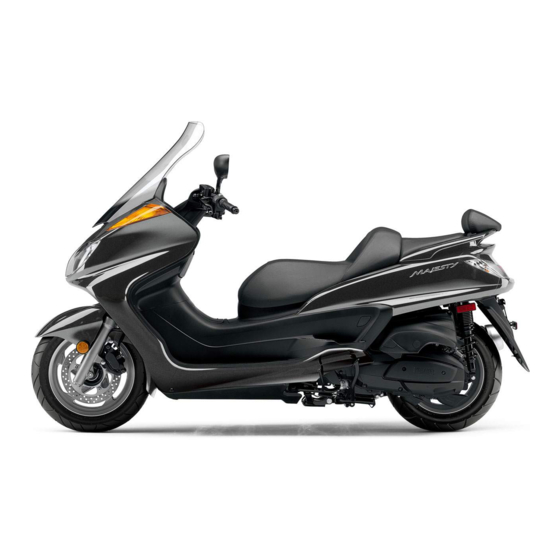
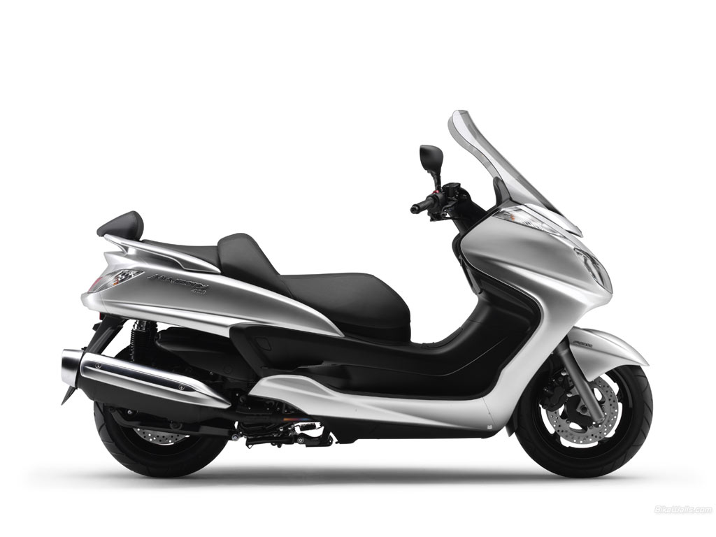
- MAJESTY 400
- Owner’s manual
-
Contents
-
Table of Contents
-
Troubleshooting
-
Bookmarks
Quick Links
OWNER’S MANUAL
YP400
YP400A
5RU-28199-E4
Related Manuals for Yamaha MAJESTY 400
Summary of Contents for Yamaha MAJESTY 400
-
Page 1
OWNER’S MANUAL YP400 YP400A 5RU-28199-E4… -
Page 2
EAU26944 DECLARATION of CONFORMITY Company: YAMAHA MOTOR ELECTRONICS CO., LTD. Address: 1450-6, Mori, Mori-Machi, Shuchi-gun, Shizuoka-Ken, 437-0292 Japan Hereby declare that the product: Kind of equipment: IMMOBILIZER Type-designation: 5SL-00 is in compliance with following norm(s) or documents: R&TTE Directive(1999/5/EC) EN300 330-2 v1.1.1(2001-6), EN60950-1(2001) -
Page 3
EAU10110 Welcome to the Yamaha world of motorcycling! As the owner of the YP400/YP400A, you are benefiting from Yamaha’s vast experience and newest technology regarding the design and manufacture of high-quality products, which have earned Yamaha a reputation for dependability. -
Page 4
This manual should be considered a permanent part of this scooter and should remain with it even if the scooter is sub- sequently sold. Yamaha continually seeks advancements in product design and quality. Therefore, while this manual contains the most current product information available at the time of printing, there may be minor discrepancies between your scooter and this manual. -
Page 5
IMPORTANT MANUAL INFORMATION EAU10200 YP400/YP400A OWNER’S MANUAL ©2007 by Yamaha Motor Co., Ltd. 1st edition, August 2007 All rights reserved. Any reprinting or unauthorized use without the written permission of Yamaha Motor Co., Ltd. is expressly prohibited. Printed in Japan. -
Page 6: Table Of Contents
TABLE OF CONTENTS SAFETY INFORMATION ….1-1 Ignition circuit cut-off system ..3-20 Valve clearance ……6-22 Further safe-riding points ….1-4 Tires ……….6-22 PRE-OPERATION CHECKS ….4-1 Cast wheels ……..6-24 DESCRIPTION ……..2-1 Pre-operation check list ….4-2 Front and rear brake lever free Left view ………..2-1 play ……….
-
Page 7
TABLE OF CONTENTS Replacing the license plate light bulb ……….6-38 Replacing an auxiliary light bulb ..6-38 Troubleshooting ……6-39 Troubleshooting charts ….6-40 SCOOTER CARE AND STORAGE ………..7-1 Matte color caution ……7-1 Care ……….7-1 Storage ……….7-3 SPECIFICATIONS ……8-1 CONSUMER INFORMATION….9-1 Identification numbers …..9-1… -
Page 8: Safety Information
SAFETY INFORMATION EAU10261 TIONS. Many accidents involve inexperi- enced operators. In fact, many op- SCOOTERS ARE SINGLE TRACK Safe riding erators who have been involved in VEHICLES. THEIR SAFE USE AND Always make pre-operation accidents do not even have a cur- OPERATION DEPENDENT checks.
-
Page 9
SAFETY INFORMATION Always signal before turning or ries. The use of a safety helmet is the approved by Yamaha, or the removal of changing lanes. Make sure that single most critical factor in the preven- original equipment, may render the other motorists can see you. -
Page 10
Gasoline and exhaust gas this scooter. Since Yamaha cannot test should be kept to a minimum. GASOLINE IS HIGHLY FLAMMA- all other accessories that may be avail-… -
Page 11: Further Safe-Riding Points
SAFETY INFORMATION Take care not to spill any gaso- sene heater, or near an open EAU10371 Further safe-riding points line on the engine or exhaust flame), otherwise it could catch Be sure to signal clearly when system when refueling. fire. making turns.
-
Page 12
SAFETY INFORMATION and ankle so they do not flap), and a bright colored jacket. Do not carry too much luggage on the scooter. An overloaded scoot- er is unstable. -
Page 13
SAFETY INFORMATION… -
Page 14: Description
DESCRIPTION EAU10410 Left view 1. Headlight (page 6-35) 9. Air filter element (left) (page 6-19) 2. Fuel tank cap (page 3-13) 10. Engine oil filter element (page 6-13) 3. Rear storage compartment (page 3-17) 11. Sidestand (page 3-19, 6-29) 4. V-belt case air filter element (page 6-19) 5.
-
Page 15: Right View
DESCRIPTION EAU10420 Right view 1. Grab bar (page 5-2) 2. Passenger seat (page 3-15) 3. Rider seat (page 3-15) 4. Coolant reservoir (page 6-17) 5. Radiator 6. Centerstand (page 6-29) 7. Air filter element (right) (page 6-19) 8. Shock absorber assembly spring preload adjusting ring (page 3-18)
-
Page 16: Controls And Instruments
DESCRIPTION EAU10430 Controls and instruments 1. Rear brake lever (page 3-11) 9. Throttle grip (page 6-22) 2. Left handlebar switches (page 3-9) 10. Front storage compartment B (page 3-17) 3. Rear brake lock lever (page 3-11) 11. Main switch/steering lock (page 3-2) 4.
-
Page 17: Instrument And Control Functions
Do not expose any key to exces- the vehicle along with all three keys to sively high temperatures. a Yamaha dealer to have them re-reg- Do not place any key close to istered. Do not use the key with the red magnets (this includes, but not bow for driving.
-
Page 18: Main Switch/Steering Lock
INSTRUMENT AND CONTROL FUNCTIONS as they may cause signal inter- EAU10471 come on, and the engine can be start- Main switch/steering lock ference. ed. The key cannot be removed. NOTE: The headlights come on automatically when the engine is started and stay on until the key is turned to “OFF”…
-
Page 19: Indicator And Warning Lights
INSTRUMENT AND CONTROL FUNCTIONS To unlock the steering wise the battery may discharge. EAU11003 Indicator and warning lights Push the key in, and then turn it to “OFF” while still pushing it. EWA10060 WARNING Never turn the key to “OFF” or “LOCK”…
-
Page 20
“ ” and turning the key for a few seconds, then go off, have a to “ON”. The warning light should come Yamaha dealer check the electrical cir- EAU11480 Engine trouble warning light “ ” on for a few seconds, and then go off. If cuit. -
Page 21: Speedometer
INSTRUMENT AND CONTROL FUNCTIONS EAU11601 EAU11872 EAU34136 Speedometer Tachometer Multi-function display EWA12311 WARNING Be sure to stop the vehicle before making any setting changes to the multi-function display. 1. Speedometer 1. Tachometer 2. Tachometer red zone The speedometer shows the riding The electric tachometer allows the rider speed.
-
Page 22
INSTRUMENT AND CONTROL FUNCTIONS cator started flashing) tor will start flashing, and the display will a self-diagnosis device automatically change to the fuel re- a clock serve tripmeter mode “TRIP F” and an ambient temperature display start counting the distance traveled an oil change indicator from that point. -
Page 23: V-Belt Replacement Indicator
3. If the indicator does not come on, CAUTION: in the fuel tank. The display segments have a Yamaha dealer check the Do not operate the engine if it is of the fuel meter disappear towards “E” electrical circuit.
-
Page 24: Self-Diagnosis Device
Yamaha dealer check the two-digit error code when the key is any error codes, note the code number, electrical circuit. turned to “ON”. and then have a Yamaha dealer check the vehicle. NOTE: Self-diagnosis device If the multi-function display indicates er-…
-
Page 25: Anti-Theft Alarm (Optional)
This display shows the ambient tem- This model can be equipped with an perature from –10 °C to 50 °C in 1 °C optional anti-theft alarm by a Yamaha Left increments. The temperature displayed dealer. Contact a Yamaha dealer for may vary from the ambient tempera- more information.
-
Page 26
INSTRUMENT AND CONTROL FUNCTIONS Right leased, the switch returns to the center EAU42810 position. To cancel the turn signal (for ABS models) lights, push the switch in after it has re- The engine trouble warning light and turned to the center position. ABS warning light will come on when the key is turned to “ON”… -
Page 27: Front Brake Lever
INSTRUMENT AND CONTROL FUNCTIONS EAU12900 EAU12950 EAU12962 Front brake lever Rear brake lever Rear brake lock lever 1. Front brake lever 1. Rear brake lever 1. Rear brake lock lever The front brake lever is located on the The rear brake lever is located on the This vehicle is equipped with a rear right handlebar grip.
-
Page 28: Abs (For Abs Models)
ABS (for ABS models) To provide secure locking of the When the ABS is activated, the The Yamaha ABS (Anti-lock Brake rear wheel, apply the rear brake le- brakes are operated in the usual System) features a dual electronic con- ver first before moving the rear way.
-
Page 29: Fuel Tank Cap
INSTRUMENT AND CONTROL FUNCTIONS EAU13162 move it. Fuel tank cap 3. Close the lid. EWA11120 WARNING To open the fuel tank cap 1. Open the lid by sliding the lever Be sure that the fuel tank cap is forward, and then pull the lever up. properly installed and locked before riding the scooter.
-
Page 30: Fuel
EWA10880 cause unrepairable damage to WARNING the catalytic converter. Your Yamaha engine has been de- Do not overfill the fuel tank, oth- Never park the vehicle near pos- signed to use regular unleaded gaso- erwise it may overflow when the…
-
Page 31: Seats
INSTRUMENT AND CONTROL FUNCTIONS EAU34140 To close the rider seat Seats 1. Fold the rider seat down, and then push it down to lock it in place. 2. Remove the key from the main switch if the scooter will be left un- attended.
-
Page 32: Adjusting The Rider Seat
INSTRUMENT AND CONTROL FUNCTIONS To install the passenger seat EAU34150 Adjusting the rider seat 1. Insert the projections on the pas- senger seat into the holders as shown, place the passenger seat in the original position, and then in- stall the bolt. 1.
-
Page 33: Storage Compartments
INSTRUMENT AND CONTROL FUNCTIONS EAU14492 and then remove it. Storage compartments Front storage compartment A To open the storage compartment when it is locked, insert the key in the lock, turn it counterclockwise, and then grasp the lock while pushing the button To open the storage compartment when it is unlocked, simply grasp the 1.
-
Page 34: Adjusting The Shock Absorber Assemblies
INSTRUMENT AND CONTROL FUNCTIONS being washed, wrap any articles EAU14890 Adjusting the shock absorber stored in the compartment in a assemblies plastic bag. Do not keep anything valuable or breakable in the storage com- partment. ECA11100 CAUTION: Do not leave the rider seat open for an extended period of time, other- 1.
-
Page 35: Sidestand
Yamaha’s ignition circuit cut-off Standard: system has been designed to assist the operator in fulfilling the respon- Maximum (hard): sibility of raising the sidestand be- fore starting off. Therefore, check this system regularly as described below and have a Yamaha dealer re- 3-19…
-
Page 36: Ignition Circuit Cut-Off System
It cuts the running engine when the sidestand is moved down. Periodically check the operation of the ignition circuit cut-off system according to the following procedure. EWA10250 WARNING If a malfunction is noted, have a Yamaha dealer check the system be- fore riding. 3-20…
-
Page 37
Does the engine start? The sidestand switch may be defective. The scooter should not be ridden until checked by a Yamaha dealer. With the engine still off: 6. Move the sidestand up. 7. Keep the front or rear brake applied. -
Page 38: Pre-Operation Checks
PRE-OPERATION CHECKS EAU15593 The condition of a vehicle is the owner’s responsibility. Vital components can start to deteriorate quickly and unexpectedly, even if the vehicle remains unused (for example, as a result of exposure to the elements). Any damage, fluid leakage or loss of tire air pressure could have serious consequences.
-
Page 39: Pre-Operation Check List
If necessary, add recommended brake fluid to specified level. Check hydraulic system for leakage. Make sure that operation is smooth. Check cable free play. Throttle grip 6-22, 6-29 If necessary, have Yamaha dealer adjust cable free play and lubricate cable and grip housing.
-
Page 40
Make sure that all nuts, bolts and screws are properly tightened. Chassis fasteners — Tighten if necessary. Instruments, lights, signals Check operation. — and switches Correct if necessary. Check operation of ignition circuit cut-off system. Sidestand switch 3-19 If system is defective, have Yamaha dealer check vehicle. -
Page 41: Operation And Important Riding Points
ECA11040 Consult a Yamaha dealer re- In order for the ignition circuit cut-off CAUTION: garding any control or function system to enable starting, the side-…
-
Page 42: Starting Off
OPERATION AND IMPORTANT RIDING POINTS EAU45091 EAU16780 EAU16792 Starting off Acceleration and deceleration Braking 1. While pulling the rear brake lever 1. Close the throttle completely. with your left hand and holding the 2. Apply both front and rear brakes grab bar with your right hand, push simultaneously while gradually in- the scooter off the centerstand.
-
Page 43: Tips For Reducing Fuel Consumption
OPERATION AND IMPORTANT RIDING POINTS Rear ing downhill can be very diffi- EAU16820 Tips for reducing fuel cult. consumption Fuel consumption depends largely on your riding style. Consider the following tips to reduce fuel consumption: Avoid high engine speeds during acceleration.
-
Page 44: Engine Break-In
Yamaha dealer check the vehi- avoided. ECA10380 cle. CAUTION: EAU34320 Never park in an area where there are fire hazards such as grass or 0–1000 km (0–600 mi)
-
Page 45: Periodic Maintenance And Minor Repair
Con- safest and most efficient condition pos- sult a Yamaha dealer for proper sible. The most important points of in- maintenance intervals. spection, adjustment, and lubrication are explained on the following pages.
-
Page 46
PERIODIC MAINTENANCE AND MINOR REPAIR NOTE: If you do not have the tools or experi- ence required for a particular job, have a Yamaha dealer perform it for you. EWA10350 WARNING Modifications approved Yamaha may cause loss of perfor- mance and render the vehicle un- safe for use. -
Page 47: Periodic Maintenance And Lubrication Chart
From 50000 km (30000 mi), repeat the maintenance intervals starting from 10000 km (6000 mi). Items marked with an asterisk should be performed by a Yamaha dealer as they require special tools, data and technical skills.
-
Page 48
PERIODIC MAINTENANCE AND MINOR REPAIR ODOMETER READING ANNUAL ITEM CHECK OR MAINTENANCE JOB 1000 km 10000 km 20000 km 30000 km 40000 km CHECK (600 mi) (6000 mi) (12000 mi) (18000 mi) (24000 mi) √ √ √ √ √ Check for cracks or damage. 9 * Brake hoses Replace. -
Page 49
PERIODIC MAINTENANCE AND MINOR REPAIR ODOMETER READING ANNUAL ITEM CHECK OR MAINTENANCE JOB 1000 km 10000 km 20000 km 30000 km 40000 km CHECK (600 mi) (6000 mi) (12000 mi) (18000 mi) (24000 mi) Change. (See pages 3-5 and √ When the oil change indicator flashes [every 5000 km (3000 mi)] 6-13.) Engine oil… -
Page 50
PERIODIC MAINTENANCE AND MINOR REPAIR EAU34490 NOTE: The air filters and V-belt filter need more frequent service if you are riding in unusually wet or dusty areas. Hydraulic brake service Regularly check and, if necessary, correct the brake fluid level. Every two years replace the internal components of the brake master cylinders and calipers, and change the brake fluid. -
Page 51: Removing And Installing Cowlings And Panels
PERIODIC MAINTENANCE AND MINOR REPAIR EAU18712 Removing and installing cowlings and panels The cowlings and panels shown need to be removed to perform some of the maintenance jobs described in this chapter. Refer to this section each time a cowling or panel needs to be re- moved and installed.
-
Page 52
PERIODIC MAINTENANCE AND MINOR REPAIR Cowling B To install the cowling Place the cowling in the original posi- To remove the cowling tion, and then install the screws. 1. Remove the screws. Cowlings C and D To remove one of the cowlings 1. -
Page 53
PERIODIC MAINTENANCE AND MINOR REPAIR 2. Install the screw access cover by 1. Left floorboard mat 1. Cowling E placing it in its original position. 2. Remove the cowling screws. To install the cowling 3. Install the grab bar by installing the 1. -
Page 54
PERIODIC MAINTENANCE AND MINOR REPAIR EAU34290 To install the panel Place the panel in the original position, Panel A and then install the bolts. To remove the panel 1. Remove the bolts. 1. Panel B 2. Screw To install the panel Place the panel in the original position, Panel B and then install the screws. -
Page 55: Checking The Spark Plug
If the spark plug shows a distinctly dif- ferent color, the engine could be oper- ating improperly. Do not attempt to diagnose such problems yourself. In- stead, have a Yamaha dealer check the vehicle. 1. Spark plug cap 2. Check the spark plug for electrode 4.
-
Page 56
PERIODIC MAINTENANCE AND MINOR REPAIR necessary. spark plug wrench, and then tight- en it to the specified torque. Specified spark plug: NGK/CR7E Tightening torque: Spark plug: To install the spark plug 12.5 Nm (1.25 m·kgf, 9 ft·lbf) 1. Measure the spark plug gap with a wire thickness gauge and, if nec- NOTE: essary, adjust the gap to specifica-… -
Page 57: Check/Change Engine Oil Level
PERIODIC MAINTENANCE AND MINOR REPAIR EAU34183 again to check the oil level. To change the engine oil (with or Engine oil and oil filter without oil filter element replace- NOTE: element ment) The engine oil should be between the The engine oil level should be checked 1.
-
Page 58
PERIODIC MAINTENANCE AND MINOR REPAIR 1. Engine oil drain bolt 1. Bolt 1. Oil filter element cover 2. Washer 2. Oil filter element cover 2. O-ring 3. Compression spring 6. Remove and replace the oil filter NOTE: 4. Oil filter element element and O-rings. -
Page 59: Reset Oil Change Indicator
PERIODIC MAINTENANCE AND MINOR REPAIR Tightening torque: Recommended engine oil: Oil filter element cover bolt: See page 8-1. 10 Nm (1.0 m·kgf, 7.2 ft·lbf) Oil quantity: Without oil filter element replace- ment: NOTE: 1.50 L (1.59 US qt) (1.32 Imp.qt) Make sure that the O-rings are properly With oil filter element replacement: seated.
-
Page 60: Final Transmission Oil
The final transmission case must be checked for oil leakage before each ride. If any leakage is found, have a Yamaha dealer check and repair the scooter. In addition, the final transmis- sion oil must be changed as follows at the intervals specified in the periodic maintenance and lubrication chart.
-
Page 61: Coolant
PERIODIC MAINTENANCE AND MINOR REPAIR EAU20070 EWA11310 Coolant WARNING The coolant level should be checked Make sure that no foreign mate- before each ride. In addition, the cool- rial enters the final transmission ant must be changed at the intervals case.
-
Page 62
PERIODIC MAINTENANCE AND MINOR REPAIR NOTE: The coolant should be between the minimum and maximum level marks. 5. If the coolant is at or below the minimum level mark, open the coolant reservoir cap, add coolant to the maximum level mark, and then close the coolant reservoir cap. -
Page 63: Air Filter Elements And Check Hoses And V-Belt Case Air Filter Element
Left Air filter elements and check If water has been added to the hoses and V-belt case air filter coolant, have a Yamaha dealer check the antifreeze content of element the coolant as soon as possible, The air filter elements and the V-belt…
-
Page 64
PERIODIC MAINTENANCE AND MINOR REPAIR Left 6. Install the rubber cap. Left ECA12922 CAUTION: Make sure that each filter ele- ment is properly seated in its case. Always replace both air filter el- ements at the same time, other- wise poor engine performance or damage to the engine may re- sult. -
Page 65
PERIODIC MAINTENANCE AND MINOR REPAIR Cleaning the V-belt case air filter el- necessary. ement 8. Install the V-belt case air filter ele- 1. Remove cowling (See ment by installing the screws. page 6-7.) 9. Install the V-belt air filter case cov- 2. -
Page 66: Checking The Throttle Cable Free Play
To prevent this note the following points regarding the from occurring, the valve clearance specified tires. must be adjusted by a Yamaha dealer at the intervals specified in the periodic Tire air pressure maintenance and lubrication chart.
-
Page 67
EWA14660 WARNING cracked, have a Yamaha dealer re- place the tire immediately. Because loading has an enormous impact on the handling, braking,… -
Page 68: Cast Wheels
Manufacturer/model: for cracks, bends, warpage or IRC/MB67 damage before each ride. If any DUNLOP/D305FL Rear tire: damage is found, have a Yamaha Size: dealer replace the wheel. Do not 150/70-13M/C 64S attempt even the smallest repair to Manufacturer/model: the wheel. A deformed or cracked IRC/MB67 wheel must be replaced.
-
Page 69: Front And Rear Brake Lever Free Play
EAU33453 There should be no free play at the Front and rear brake lever free brake lever ends. If there is free play, play have a Yamaha dealer inspect the brake system. Front EWA14211 WARNING A soft or spongy feeling in the brake lever can indicate the presence of air in the hydraulic system.
-
Page 70: Adjusting The Rear Brake Lock Lever Cable
EWA10650 WARNING checked for wear at the intervals spec- If proper adjustment cannot be ob- ified in the periodic maintenance and tained as described, have a Yamaha lubrication chart. dealer make this adjustment. EAU22430 Front brake pads 1. Adjusting nut 2.
-
Page 71: Checking The Brake Fluid Level
EAU22580 enter the brake system, possibly caus- Checking the brake fluid level peared, have a Yamaha dealer replace ing it to become ineffective. the brake pads as a set. Before riding, check that the brake fluid…
-
Page 72: Changing The Brake Fluid
EAU23100 Changing the brake fluid Checking and lubricating the lower the boiling point of the fluid Have a Yamaha dealer change the cables and may result in vapor lock. brake fluid at the intervals specified in Brake fluid may deteriorate paint-…
-
Page 73: Checking And Lubricating The Throttle Grip And Cable
PERIODIC MAINTENANCE AND MINOR REPAIR EAU23111 EAU23172 EAU23212 Checking and lubricating the Lubricating the front and rear Checking and lubricating the throttle grip and cable brake levers centerstand and sidestand The operation of the throttle grip should be checked before each ride. In addi- tion, the cable should be lubricated at the intervals specified in the periodic maintenance chart.
-
Page 74: Checking The Front Fork
If the centerstand or sidestand does fork must be checked as follows at the not move up and down smoothly, intervals specified in the periodic main- have a Yamaha dealer check or re- tenance and lubrication chart. pair it. To check the condition…
-
Page 75: Checking The Steering
2. Hold the lower ends of the front fork legs and try to move them for- ward and backward. If any free play can be felt, have a Yamaha dealer check or repair the steering. 6-31…
-
Page 76: Battery
Electrolyte is poisonous and To charge the battery battery, a special (constant-volt- dangerous since it contains sul- Have a Yamaha dealer charge the bat- age) battery charger is required. furic acid, which causes severe tery as soon as possible if it seems to Using a conventional battery burns.
-
Page 77: Replacing The Fuses
PERIODIC MAINTENANCE AND MINOR REPAIR er, have a Yamaha dealer EAU42820 Replacing the fuses charge your battery. The main fuse and the fuse box, which contains the fuses for the individual cir- cuits, are located behind cowling A. (See page 6-7.) If a fuse is blown, replace it as follows.
-
Page 78
PERIODIC MAINTENANCE AND MINOR REPAIR (for ABS models) (for non-ABS models) (for ABS models) 1. Fuse box 1. Ignition fuse 1. Ignition fuse 2. ABS motor fuse 2. Signaling system fuse 2. Signaling system fuse 3. ABS control unit fuse 3. -
Page 79: Replacing A Headlight Bulb
Yamaha dealer 40.0 A headlights. If a headlight bulb burns Ignition fuse: check the electrical system. 10.0 A out, have a Yamaha dealer replace it Signaling system fuse: and, if necessary, adjust the headlight 10.0 A beam. Headlight fuse: 25.0 A…
-
Page 80: Tail/Brake Light
LED-type tail/brake light. 1. Place the scooter on the center- If the tail/brake light does not come on, stand. have a Yamaha dealer check it. 2. Remove panel A. (See page 6-7.) 3. Remove the windshield by remov- ing the screws.
-
Page 81: Replacing A Rear Turn Signal Light Bulb
PERIODIC MAINTENANCE AND MINOR REPAIR clockwise. EAU34260 push it in, and then turn it clock- Replacing a rear turn signal 7. Insert a new bulb into the socket, wise until it stops. light bulb push it in, and then turn it clock- 6.
-
Page 82: Replacing The License Plate Light Bulb
PERIODIC MAINTENANCE AND MINOR REPAIR EAU34271 EAU42800 Replacing the license plate Replacing an auxiliary light light bulb bulb 1. Place the scooter on the center- 1. Place the scooter on the center- stand. stand. 2. Remove cowling (See 2. Remove panel A. (See page 6-7.) page 6-7.) 3.
-
Page 83: Troubleshooting
However, should your scooter re- 5. Remove the auxiliary light bulb quire any repair, take it to a Yamaha socket (together with the bulb) by dealer, whose skilled technicians have turning it counterclockwise.
-
Page 84: Troubleshooting Charts
Remove the spark plug and check the electrodes. The engine does not start. Have a Yamaha dealer check the vehicle. Check the battery. 4. Battery The engine turns over The battery is good.
-
Page 85
Start the engine. If the engine overheats again, have a The coolant level Yamaha dealer check and repair the cooling system. is OK. NOTE: If coolant is not available, tap water can be temporarily used instead, provided that it is changed to the recommended coolant as soon as possible. -
Page 86: Scooter Care And Storage
Be Rust and corrosion can develop even if ECA10781 CAUTION: sure to consult a Yamaha dealer for high-quality components are used. A advice on what products to use be- rusty exhaust pipe may go unnoticed Avoid using strong acidic wheel fore cleaning the vehicle.
-
Page 87
SCOOTER CARE AND STORAGE cleaning products, solvent or After normal use creases the corrosive action of the thinner, fuel (gasoline), rust re- Remove dirt with warm water, a mild salt. movers or inhibitors, brake flu- detergent, and a soft, clean sponge, 2. -
Page 88: Storage
SCOOTER CARE AND STORAGE fore storing or covering it. EAU36560 NOTE: Storage EWA10940 Consult a Yamaha dealer for advice on WARNING what products to use. Short-term Make sure that there is no oil or Always store your scooter in a cool, dry wax on the brakes or tires.
-
Page 89
SCOOTER CARE AND STORAGE fuel from deteriorating. pivoting points of all levers and 3. Perform the following steps to pro- pedals as well as of the sidestand/ tect the cylinder, piston rings, etc. centerstand. from corrosion. 5. Check and, if necessary, correct a. -
Page 90: Specifications
SPECIFICATIONS EAU2633M Starting system: Cooling system: Electric starter Coolant reservoir capacity (up to the maxi- Lubrication system: Dimensions: mum level mark): Wet sump 0.32 L (0.34 US qt) (0.28 Imp.qt) Overall length: Engine oil: Radiator capacity (including all routes): 2230 mm (87.8 in) Type: 1.57 L (1.66 US qt) (1.38 Imp.qt) Overall width:…
-
Page 91
SPECIFICATIONS Secondary reduction ratio: Loading: Front brake: 42/16 (2.625) Maximum load: Type: Transmission type: YP400 189 kg (417 lb) Dual disc brake V-belt automatic YP400A 185 kg (408 lb) Operation: Operation: * (Total weight of rider, passenger, cargo Right hand operation Centrifugal automatic type and accessories) Recommended fluid:… -
Page 92
SPECIFICATIONS Battery: Fuses: Model: Main fuse: GT9B-4 40.0 A Voltage, capacity: Headlight fuse: 12 V, 8.0 Ah 25.0 A Headlight: Signaling system fuse: 10.0 A Bulb type: Ignition fuse: Halogen bulb Bulb voltage, wattage × quantity: 10.0 A Radiator fan fuse: Headlight: 10.0 A 12 V, 60 W/55.0 W ×… -
Page 93: Consumer Information
Record the key identification number, vehicle identification number and mod- el label information in the spaces pro- vided below for assistance when ordering spare parts from a Yamaha dealer or for reference in case the vehi- cle is stolen. KEY IDENTIFICATION NUMBER: 1.
-
Page 94
The model label is affixed to the inside of the rear storage compartment. (See page 3-17.) Record the information on this label in the space provided. This in- formation will be needed when ordering spare parts from a Yamaha dealer. -
Page 95
INDEX Front and rear brake lever free play ..6-25 Pre-operation check list……4-2 Front and rear brake pads, checking..6-26 ABS (for ABS models) ……3-12 Front fork, checking……… 6-30 ABS warning light (for ABS models) ..3-4 Rear brake lock lever ……3-11 Fuel ………… -
Page 96
INDEX Valve clearance ……..6-22 Vehicle identification number ….9-1 Wheel bearings, checking……. 6-31 Wheels ………… 6-24… -
Page 98
YAMAHA MOTOR CO., LTD. YAMAHA MOTOR CO., LTD. PRINTED ON RECYCLED PAPER PRINTED ON RECYCLED PAPER PRINTED IN JAPAN PRINTED IN JAPAN 2007.9–0.2×1 ! 2007.9–0.2×1 !
Интернет-магазин
OILSHOP55.RU
Масла и смазки для автомобилей и мотоциклов, автохимия, расходные материалы, запчасти.
Суббота, 23.09.2023, 09:04
Приветствую Вас
Гость
| ВХОД НА САЙТ
|
Поиск товара
|
|
-
МОИ ЗАКАЗЫ
-
АКЦИИ и СКИДКИ
-
Каталог товаров
-
Запчасти для скутеров
-
Запчасти для мопедов
-
Покрышки для скутеров
-
Мото фильтры
-
Доставка
-
Контакты
-
Технический раздел
-
Каталог статей
-
Как заказать ?
-
Скачать прайс
 КОРЗИНА КОРЗИНА |
|
Ваша корзина пуста |
| ВОЙТИ НА САЙТ | |||||||
|
| ПОИСК ПО МАГАЗИНУ |
|
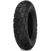
Товары со скидкой!!! Покрышка 426 130/60-13 SHINKO внедорожная 4990 руб. Рамка спидометра Yamaha Aprio (4JP) 1620 руб. |
| ОНЛАЙН КОНСУЛЬТАНТ |
|
Для добавления необходима авторизация |
| НАШ ОПРОС |
|
Оцените мой сайт Отлично Хорошо Неплохо Плохо Ужасно Результаты | Архив опросов Всего ответов: 280 |
| КАТАЛОГ ФАЙЛОВ | |||||||||
|
| ПОЛЕЗНЫЕ ССЫЛКИ |
|
|
| ВЫБЕРИТЕ ВАШ ГОРОД: |
| СТАТИСТИКА |
|
Онлайн всего: 36 Гостей: 36 Пользователей: 0 |

![]()
| Главная » Файлы » Инструкции по эксплуатации » Скутеры |
Yamaha Majesty 400 2005-2007 Инструкция по эксплуатации
|
[ · Скачать удаленно (16 Mb) ] |
08.09.2014, 15:21 |
|
Скачать руководство по обслуживанию и ремонту Yamaha Majesty 400 (ENG) Описание: Yamaha Majesty YP400 Service Manual 2005-2007 В руководстве по эксплуатации максискутера Yamaha Majesty YP-400 (GRAND MAJESTY) описаны основные моменты, связанные с правильной эксплуатацией и техническим обслуживанием скутеров данной модели. Вы можете скачать руководство эксплуатации скутера Yamaha Majesty YP-400 в двух вариантах: 1. Руководство по техническому обслуживанию и ремонту в формате PDF на английском языке 2. Инструкция по эксплуатации Yamaha Majesty 400 на русском языке в формате JPG. Для выбора варианта скачивания воспользуйтесь ссылками ниже: DOWNLOAD YAMAHA MAJESTY YP-400 Service Manual СКАЧАТЬ Руководство по эксплуатации YAMAHA MAJESTY YP-400 Запчасти для максискутера Yamaha Majesty 400 в интернет-магазине Oilshop55.RU
|
|
|
Категория: Скутеры | Добавил: Richas |
|
| Просмотров: 20711 | Загрузок: 749
| Рейтинг: 0.0/0 |

| Всего комментариев: 0 | |
| Имя *: | |
| Email *: | |
| Код *: | |
СЕГОДНЯ В НАШЕМ МАГАЗИНЕ МОЖНО ЗАКАЗАТЬ ТОВАРЫ СО СКИДКОЙ…
|
Свеча зажигания DENSO IU27 1380 руб. |
Рамка спидометра Yamaha Aprio (4JP) 1620 руб. |
Рамка для мотоциклетного номерного знака 780 руб. |

Приветствую Вас
, Гость!
Регистрация
|
Вход
Категории раздела
|
Yamaha majesty 125/150/180 [36] |
|
Yamaha (grand) majesty 250 [33] |
|
Yamaha (grand) majesty 400 [38] |
|
Maxam/Morphous CP250 [4] |
|
X-max 125/YP125R/Skycruiser [1] |
|
X-max 250/YP250R/Skycruiser [1] |
|
X-max 400 [0] |
|
Yamaha Tricity/ MBK Tryptik 2CM MW125 [1] |
|
Yamaha T-Max [8] |
|
Yamaha Versity VP300 [2] |
Вход на сайт
| Логин: | |
| Пароль: | |
| запомнить | |
|
Забыл пароль | Регистрация |
Наш опрос
Нефть не вечная. Ваши действия когда бензина не станет?
Буду хранить бензиновую технику как музейный экспонат
Пересяду на что-нибудь современное
Откажусь от мототехники
Поставлю современный двигатель
Начну бодяжить горючие смеси
Результаты | Архив опросов
Всего ответов: 49
Мини-чат
Для добавления необходима авторизация
Друзья сайта
- Магазин запчастей для скутеров OILSHOP55.RU
- Масла REPSOL
- Скутерклуб MOSQUITO’S
Статистика
![]()
Онлайн всего: 1
Гостей: 1
Пользователей: 0
»
Файлы
» Руководства Yamaha/MBK » Yamaha (grand) majesty 400
В категории материалов
: 38
Показано материалов
: 1-12
Страницы
: 1 2 3 4 »
Сортировать по
:
Дате ·
Названию ·
Рейтингу ·
Комментариям ·
Загрузкам ·
Просмотрам
Сервис мануал YP400(T)/ YP400A 34B 2009

Данный мануал у меня на руках, если что-то нужно — пишите, поделюсь скриншотом или так расскажу
Читать подробнее / Скачать »
Просмотров: 3041 | Загрузок: 97 |Добавил: laudanum16 | Дата: 19.01.2014
Комментарии (3)
Каталог частей YP400A 34BB 2010

Формат pdf (защищен), язык испанский
Модель: YP400A 34BB, г.в. документа 2009
Читать подробнее / Скачать »
Просмотров: 1325 | Загрузок: 13 |Добавил: laudanum16 | Дата: 18.11.2013
Комментарии (0)
Каталог частей YP400A 34B3 2009

Формат pdf (защищен), язык испанский
Модель: YP400A 34B3, г.в. документа 2009
Читать подробнее / Скачать »
Просмотров: 1240 | Загрузок: 4 |Добавил: laudanum16 | Дата: 18.11.2013
Комментарии (0)
Каталог частей YP400A 34B1 2008
Формат pdf (защищен), язык испанский
Модель: YP400A 34B1, г.в. документа 2007
Читать подробнее / Скачать »
Просмотров: 1278 | Загрузок: 5 |Добавил: laudanum16 | Дата: 18.11.2013
Комментарии (0)
Каталог частей YP400 5RUX 2008

Формат pdf (защищен), язык испанский
Модель: YP400 5RUX, г.в. документа 2007
Читать подробнее / Скачать »
Просмотров: 1296 | Загрузок: 4 |Добавил: laudanum16 | Дата: 18.11.2013
Комментарии (0)
Каталог частей YP400 34BA 2010
Формат pdf (защищен), язык испанский
Модель: YP400 34BA, г.в. документа 2009
Читать подробнее / Скачать »
Просмотров: 1169 | Загрузок: 1 |Добавил: laudanum16 | Дата: 18.11.2013
Комментарии (0)
Каталог частей YP400 34B2 2009
Формат pdf (защищен), язык испанский
Модель: YP400 34B2, г.в. документа 2009
Читать подробнее / Скачать »
Просмотров: 1216 | Загрузок: 0 |Добавил: laudanum16 | Дата: 18.11.2013
Комментарии (0)
Каталог частей YP400 34BD 2011
Формат pdf (защищен), язык испанский
Модель: YP400 34BE, г.в. документа 2010
Читать подробнее / Скачать »
Просмотров: 1146 | Загрузок: 4 |Добавил: laudanum16 | Дата: 18.11.2013
Комментарии (0)
Каталог частей YP400A 34BE 2011
Формат pdf (защищен), язык испанский
Модель: YP400 34BE, г.в. документа 2010
Читать подробнее / Скачать »
Просмотров: 1185 | Загрузок: 4 |Добавил: laudanum16 | Дата: 18.11.2013
Комментарии (0)
Каталог частей YP400 5RU6/ 400T 5RU8 2005

Формат pdf (защищен), язык английский
Модель: YP400 5RU6/ 400T 5RU8, г.в. документа 2004
Читать подробнее / Скачать »
Просмотров: 1828 | Загрузок: 72 |Добавил: laudanum16 | Дата: 05.11.2013
Комментарии (0)
Каталог частей YP400 5RU1
Формат pdf (защищен), язык немецкий
Модель: YP400 5RU1, г.в. документа 2003
Читать подробнее / Скачать »
Просмотров: 1079 | Загрузок: 9 |Добавил: laudanum16 | Дата: 05.11.2013
Комментарии (0)
Юзер-мануал YP400/400A 5RU-Х3 2006 РУССКИЙ
Язык русский, формат JPG (ФОТО)
Модель: YP400/400A 5RU-Х3 2006
Читать подробнее / Скачать »
Просмотров: 2187 | Загрузок: 124 |Добавил: laudanum16 | Дата: 26.09.2013
Комментарии (0)
1-12 13-24 25-36 37-38
Manufacturer: YAMAHA, Model Year: 2004,
Model line: MAJESTY 400,
Model: YAMAHA MAJESTY 400 2004
Pages: 92, PDF Size: 2.25 MB
Trending: fuse box, warning, 6-31, coolant, 6-6, coolant level, fuses
- Load previous 10 pages
Page 41 of 92

Page 42 of 92

Page 43 of 92

Page 44 of 92

Page 45 of 92

Page 46 of 92

Page 47 of 92

Page 48 of 92

Page 49 of 92

Page 50 of 92

- Load next 10 pages
Trending: fuses, coolant level, 6-31, maintenance, coolant, fuse box, warning
View, print and download for free: YAMAHA MAJESTY 400 2004 Service Manual, 92 Pages, PDF Size: 2.25 MB. Search in YAMAHA MAJESTY 400 2004 Service Manual online. CarManualsOnline.info is the largest online database of car user manuals. YAMAHA MAJESTY 400 2004 Service Manual PDF Download.
OPERATION AND IMPORTANT RIDING POINTS
5-4
2
3
4
56
7
8
9
EAU16841
Engine break-in
There is never a more important period
in the life of your engine tha
All product names, logos, and brands are property of their respective owners.
Privacy Policy | About Us & Contact
![]()
5RU-28199-E0
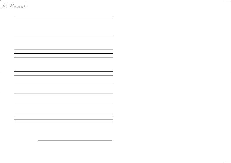
EAU26941
DECLARATION of CONFORMITY
We
Company: MORIC CO., LTD.
Address: 1450-6 Mori Mori-Machi Shuchi-gun Shizuoka 437-0292 Japan
Hereby declare that the product:
Kind of equipment: IMMOBILIZER
Type-designation:
5SL-00, 5VS-00, 5VX-00, 3HT-00, 5UX-00, 5UX-10, 5KS-00 and 5KS-10
is in compliance with following norm(s) or documents:
R&TTE Directive(1999/5/EC)
EN300 330-2 v1.1.1(2001-6), EN60950(2000)
Two or Three-Wheel Motor Vehicles Directive(97/24/EC: Chapter 8, EMC)
Place of issue: Shizuoka, Japan
Date of issue: Aug. 1st 2002
Kazuji Kawai
representative name and signature
INTRODUCTION
EAU10110
Welcome to the Yamaha world of motorcycling!
As the owner of the YP400, you are benefiting from Yamaha’s vast experience and newest technology regarding the design and manufacture of high-quality products, which have earned Yamaha a reputation for dependability.
Please take the time to read this manual thoroughly, so as to enjoy all advantages of your YP400. The owner’s manual does not only instruct you in how to operate, inspect and maintain your scooter, but also in how to safeguard yourself and others from trouble and injury.
In addition, the many tips given in this manual will help keep your scooter in the best possible condition. If you have any further questions, do not hesitate to contact your Yamaha dealer.
The Yamaha team wishes you many safe and pleasant rides. So, remember to put safety first!
IMPORTANT MANUAL INFORMATION
EAU34110
Particularly important information is distinguished in this manual by the following notations:
|
The Safety Alert Symbol means ATTENTION! BECOME ALERT! YOUR SAFETY IS |
||||||
|
INVOLVED! |
||||||
|
Failure to follow WARNING instructions could result in severe injury or death to the |
||||||
|
WARNING |
||||||
|
scooter operator, a bystander, or a person inspecting or repairing the scooter. |
||||||
|
A CAUTION indicates special precautions that must be taken to avoid damage to |
||||||
|
CAUTION: |
||||||
|
the scooter. |
||||||
|
A NOTE provides key information to make procedures easier or clearer. |
|||||
|
NOTE: |
|||||
|
NOTE: |
●This manual should be considered a permanent part of this scooter and should remain with it even if the scooter is subsequently sold.
●Yamaha continually seeks advancements in product design and quality. Therefore, while this manual contains the most current product information available at the time of printing, there may be minor discrepancies between your scooter and this manual. If you have any questions concerning this manual, please consult your Yamaha dealer.
EWA12410
 WARNING
PLEASE READ THIS MANUAL CAREFULLY AND COMPLETELY BEFORE OPERATING THIS SCOOTER.
IMPORTANT MANUAL INFORMATION
EAU10200
YP400
OWNER’S MANUAL ©2003 by Yamaha Motor Co., Ltd.
1st edition, October 2003 All rights reserved.
Any reprinting or unauthorized use without the written permission of Yamaha Motor Co., Ltd.
is expressly prohibited. Printed in Japan.

TABLE OF CONTENTS
|
SAFETY INFORMATION ………………. |
1-1 |
|
Further safe-riding points …………….. |
1-4 |
|
DESCRIPTION …………………………….. |
2-1 |
|
Left view ……………………………………. |
2-1 |
|
Right view ………………………………….. |
2-2 |
|
Controls and instruments……………… |
2-3 |
|
INSTRUMENT AND CONTROL |
|
|
FUNCTIONS ………………………………… |
3-1 |
|
Immobilizer system …………………….. |
3-1 |
|
Main switch/steering lock …………….. |
3-2 |
|
Indicator and warning lights …………. |
3-3 |
|
Speedometer …………………………….. |
3-4 |
|
Tachometer ………………………………. |
3-4 |
|
Multi-function display ………………….. |
3-5 |
|
Anti-theft alarm (optional) ……………. |
3-8 |
|
Handlebar switches ……………………. |
3-9 |
|
Front brake lever ……………………… |
3-10 |
|
Rear brake lever ………………………. |
3-10 |
|
Rear brake lock lever ………………… |
3-11 |
|
Fuel tank cap …………………………… |
3-11 |
|
Fuel ………………………………………… |
3-12 |
|
Catalytic converter ……………………. |
3-13 |
|
Seats ……………………………………… |
3-13 |
|
Adjusting the rider seat ……………… |
3-15 |
|
Storage compartments ……………… |
3-15 |
|
Sidestand ………………………………… |
3-17 |
|
Ignition circuit cut-off system ……… |
3-17 |
|
PRE-OPERATION CHECKS …………. |
4-1 |
|
Pre-operation check list ………………. |
4-2 |
|
OPERATION AND IMPORTANT |
|
|
RIDING POINTS……………………………. |
5-1 |
|
Starting the engine …………………….. |
5-1 |
|
Starting off ………………………………… |
5-2 |
|
Acceleration and deceleration ……… |
5-2 |
|
Braking …………………………………….. |
5-2 |
|
Tips for reducing fuel |
|
|
consumption ……………………………. |
5-3 |
|
Engine break-in …………………………. |
5-4 |
|
Parking …………………………………….. |
5-4 |
|
PERIODIC MAINTENANCE AND |
|
|
MINOR REPAIR ……………………………. |
6-1 |
|
Owner’s tool kit ………………………….. |
6-1 |
|
Periodic maintenance and |
|
|
lubrication chart ……………………….. |
6-3 |
|
Removing and installing cowlings |
|
|
and panels ……………………………… |
6-6 |
|
Checking the spark plug ……………. |
6-10 |
|
Engine oil and oil filter element ….. |
6-12 |
|
Final transmission oil ………………… |
6-15 |
|
Coolant …………………………………… |
6-16 |
|
Air filter elements and check hoses |
|
|
and V-belt case air filter |
|
|
element ………………………………… |
6-18 |
|
Adjusting the throttle cable free |
|
|
play ……………………………………… |
6-20 |
|
Adjusting the valve clearance ……. |
6-21 |
|
Tires ………………………………………. |
6-21 |
|
Cast wheels ……………………………. |
6-23 |
|
Front and rear brake lever free |
|
|
play ……………………………………… |
6-24 |
|
Adjusting the rear brake lock lever |
|
|
cable ……………………………………. |
6-24 |
|
Checking the front and rear brake |
|
|
pads …………………………………….. |
6-25 |
|
Checking the brake fluid level ……. |
6-25 |
|
Changing the brake fluid …………… |
6-26 |
|
Checking and lubricating the |
|
|
cables ………………………………….. |
6-27 |
|
Checking and lubricating the |
|
|
throttle grip and cable …………….. |
6-27 |
|
Lubricating the front and rear |
|
|
brake levers ………………………….. |
6-27 |
|
Checking and lubricating the |
|
|
centerstand and sidestand ……… |
6-28 |
|
Checking the front fork ……………… |
6-28 |
|
Checking the steering ………………. |
6-29 |
|
Checking the wheel bearings …….. |
6-30 |
|
Battery ……………………………………. |
6-30 |
|
Replacing the fuses …………………. |
6-31 |
|
Replacing a headlight bulb ……….. |
6-33 |
|
Tail/brake light …………………………. |
6-33 |
|
Replacing a front turn signal light |
|
|
bulb or an auxiliary light bulb …… |
6-34 |
|
Replacing a rear turn signal light |
|
|
bulb ……………………………………… |
6-35 |
|
Replacing the license plate light |
|
|
bulb ……………………………………… |
6-36 |

TABLE OF CONTENTS
|
Troubleshooting ……………………….. |
6-36 |
|
Troubleshooting charts ……………… |
6-37 |
|
SCOOTER CARE AND STORAGE …. |
7-1 |
|
Care …………………………………………. |
7-1 |
|
Storage …………………………………….. |
7-3 |
|
SPECIFICATIONS ………………………… |
8-1 |
|
CONSUMER INFORMATION ………… |
9-1 |
|
Identification numbers ………………… |
9-1 |

 SAFETY INFORMATION
EAU10260
SCOOTERS ARE SINGLE TRACK VEHICLES. THEIR SAFE USE AND OPERATION ARE DEPENDENT
1UPON THE USE OF PROPER RIDING TECHNIQUES AS WELL AS THE EXPERTISE OF THE OPERATOR. EVERY OPERATOR SHOULD KNOW THE FOLLOWING REQUIREMENTS BEFORE RIDING THIS SCOOTER.
HE OR SHE SHOULD:
●OBTAIN THOROUGH INSTRUCTIONS FROM A COMPETENT SOURCE ON ALL ASPECTS OF SCOOTER OPERATION.
●OBSERVE THE WARNINGS AND MAINTENANCE REQUIREMENTS IN THE OWNER’S MANUAL.
●OBTAIN QUALIFIED TRAINING IN SAFE AND PROPER RIDING TECHNIQUES.
●OBTAIN PROFESSIONAL TECHNICAL SERVICE AS INDICATED BY THE OWNER’S MANUAL AND/OR WHEN MADE NECES-
SARY BY MECHANICAL CONDITIONS.
Safe riding
●Always make pre-operation checks. Careful checks may help prevent an accident.
●This scooter is designed to carry the operator and passenger.
●The failure of motorists to detect and recognize scooters in traffic is the predominating cause of automobile/scooter accidents. Many accidents have been caused by an automobile driver who did not see the scooter. Making yourself conspicuous appears to be very effective in reducing the chance of this type of accident.
●Therefore:
●Wear a brightly colored jacket.
●Use extra caution when approaching and passing through intersections, since intersections are the most likely places for scooter accidents to occur.
●Ride where other motorists can
1-1
see you. Avoid riding in another motorist’s blind spot.
●Many accidents involve inexperienced operators. In fact, many operators who have been involved in accidents do not even have a current driver’s license.
●Make sure that you are qualified and that you only lend your scooter to other qualified operators.
●Know your skills and limits. Staying within your limits may help you to avoid an accident.
●We recommend that you practice riding your scooter where there is no traffic until you have become thoroughly familiar with the scooter and all of its controls.
●Many accidents have been caused by error of the scooter operator. A typical error made by the operator is veering wide on a turn due to EXCESSIVE SPEED or undercornering (insufficient lean angle for

 SAFETY INFORMATION
the speed).
●Always obey the speed limit and never travel faster than warranted by road and traffic conditions.
●Always signal before turning or changing lanes. Make sure that other motorists can see you.
●The posture of the operator and passenger is important for proper control.
●The operator should keep both hands on the handlebar and both feet on the footboard during operation to maintain control of the scooter.
●The passenger should always hold onto the operator, the seat strap or grab bar, if equipped, with both hands and keep both feet on the passenger footrests.
●Never carry a passenger unless he or she can firmly place both feet on the passenger footrests.
●Never ride under the influence of alcohol or other drugs.
●This scooter is designed for
on-road use only. It is not suitable for off-road use.
Protective apparel
The majority of fatalities from scooter accidents are the result of head injuries. The use of a safety helmet is the single most critical factor in the prevention or reduction of head injuries.
●Always wear an approved helmet.
●Wear a face shield or goggles. Wind in your unprotected eyes could contribute to an impairment of vision which could delay seeing a hazard.
●The use of a jacket, substantial shoes, trousers, gloves, etc., is effective in preventing or reducing abrasions or lacerations.
●Never wear loose-fitting clothes, otherwise they could catch on the control levers or wheels and cause injury or an accident.
●Never touch the engine or exhaust system during or after operation. They become very hot and can cause burns. Always wear protec-
tive clothing that covers your legs, ankles, and feet.
●Passengers should also observe the above precautions.
|
Modifications |
1 |
|
Modifications made to this scooter not |
|
|
approved by Yamaha, or the removal of |
|
|
original equipment, may render the |
|
|
scooter unsafe for use and may cause |
|
|
severe personal injury. Modifications |
|
|
may also make your scooter illegal to |
|
|
use. |
|
|
Loading and accessories |
|
|
Adding accessories or cargo to your |
|
|
scooter can adversely affect stability |
|
|
and handling if the weight distribution of |
|
|
the scooter is changed. To avoid the |
|
|
possibility of an accident, use extreme |
|
|
caution when adding cargo or accesso- |
|
|
ries to your scooter. Use extra care |
|
|
when riding a scooter that has added |
|
|
cargo or accessories. Here are some |
|
|
general guidelines to follow if loading |
|
|
cargo or adding accessories to your |
|
|
scooter: |
1-2
 SAFETY INFORMATION
Loading
The total weight of the operator, passenger, accessories and cargo must not exceed the maximum load limit of
1198 kg (437 lb). When loading within this weight limit, keep the following in mind:
●Cargo and accessory weight should be kept as low and close to the scooter as possible. Make sure to distribute the weight as evenly as possible on both sides of the scooter to minimize imbalance or instability.
●Shifting weights can create a sudden imbalance. Make sure that accessories and cargo are securely attached to the scooter before riding. Check accessory mounts and cargo restraints frequently.
●Never attach any large or heavy items to the handlebar, front fork, or front fender. Such items can create unstable handling or a slow steering response.
Accessories
Genuine Yamaha accessories have been specifically designed for use on this scooter. Since Yamaha cannot test all other accessories that may be available, you must personally be responsible for the proper selection, installation and use of non-Yamaha accessories. Use extreme caution when selecting and installing any accessories.
Keep the following guidelines in mind, as well as those provided under “Loading” when mounting accessories.
●Never install accessories or carry cargo that would impair the performance of your scooter. Carefully inspect the accessory before using it to make sure that it does not in any way reduce ground clearance or cornering clearance, limit suspension travel, steering travel or control operation, or obscure lights or reflectors.
●Accessories fitted to the handlebar or the front fork area can create instability due to improper
weight distribution or aerodynamic changes. If accessories are added to the handlebar or front fork area, they must be as lightweight as possible and should be kept to a minimum.
●Bulky or large accessories may seriously affect the stability of the scooter due to aerodynamic effects. Wind may attempt to lift the scooter, or the scooter may become unstable in cross winds. These accessories may also cause instability when passing or being passed by large vehicles.
●Certain accessories can displace the operator from his or her normal riding position. This improper position limits the freedom of movement of the operator and may limit control ability, therefore, such accessories are not recommended.
●Use caution when adding electrical accessories. If electrical acces-
1-3
![]()
 SAFETY INFORMATION
sories exceed the capacity of the scooter’s electrical system an electric failure could result, which could cause a dangerous loss of lights or engine power.
Gasoline and exhaust gas
●GASOLINE IS HIGHLY FLAMMABLE:
●Always turn the engine off when refueling.
●Take care not to spill any gasoline on the engine or exhaust system when refueling.
●Never refuel while smoking or in the vicinity of an open flame.
●Never start the engine or let it run for any length of time in a closed area. The exhaust fumes are poisonous and may cause loss of consciousness and death within a short time. Always operate your scooter in an area that has adequate ventilation.
●Always turn the engine off before leaving the scooter unattended and remove the key from the main
switch. When parking the scooter, note the following:
●The engine and exhaust system may be hot, therefore, park the scooter in a place where pedestrians or children are not likely to touch these hot areas.
●Do not park the scooter on a slope or soft ground, otherwise it may fall over.
●Do not park the scooter near a flammable source (e.g., a kerosene heater, or near an open flame), otherwise it could catch fire.
●If you should swallow any gasoline, inhale a lot of gasoline vapor, or allow gasoline to get into your eyes, see your doctor immediately. If any gasoline spills on your skin or clothing, immediately wash the affected area with soap and water and change your clothes.
1-4
EAU10370
Further safe-riding points
●Be sure to signal clearly when making turns.
|
● Braking can be extremely difficult |
1 |
on a wet road. Avoid hard braking, because the scooter could slide. Apply the brakes slowly when stopping on a wet surface.
●Slow down as you approach a corner or turn. Once you have completed a turn, accelerate slowly.
●Be careful when passing parked cars. A driver might not see you and open a door in your path.
●Railroad crossings, streetcar rails, iron plates on road construction sites, and manhole covers become extremely slippery when wet. Slow down and cross them with caution. Keep the scooter upright, otherwise it could slide out from under you.
●The brake pads could get wet when you wash the scooter. After washing the scooter, check the brakes before riding.

 SAFETY INFORMATION
● Always wear a helmet, gloves, trousers (tapered around the cuff and ankle so they do not flap), and a bright colored jacket.
1 ● Do not carry too much luggage on the scooter. An overloaded scooter is unstable.
1-5
 SAFETY INFORMATION
1
1-6
DESCRIPTION
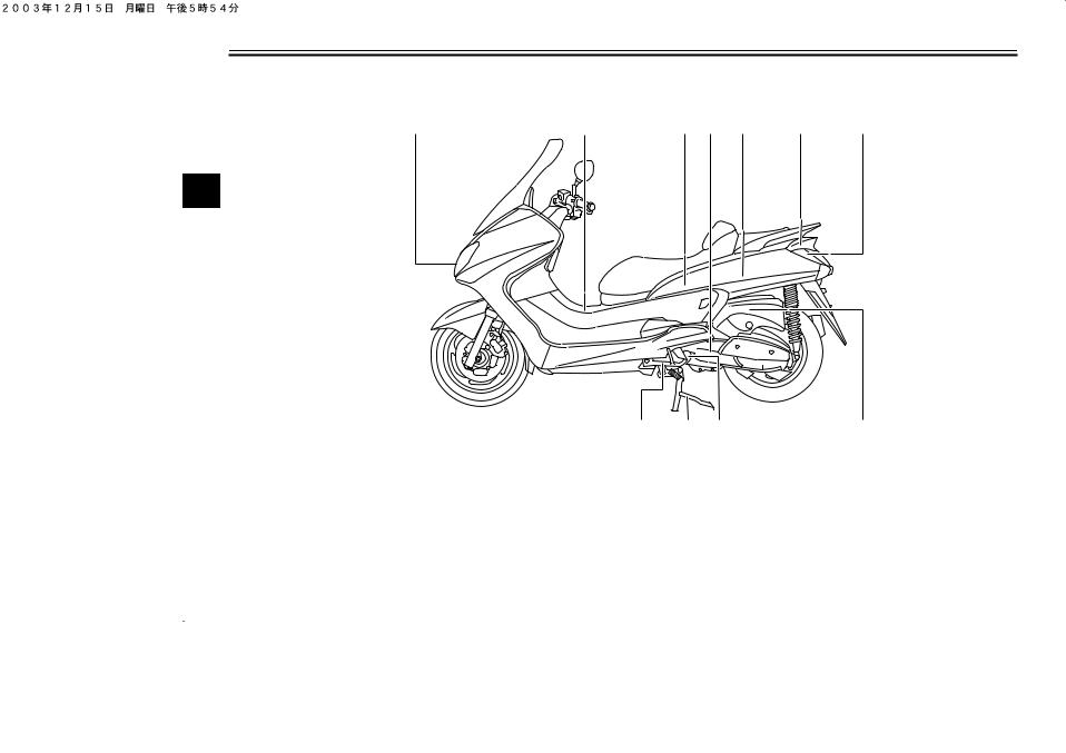
EAU10410
Left view
|
1 |
2 |
3 |
4 |
5 |
6 |
7 |
2
1.Headlight (page 6-33)
2.Fuel tank cap (page 3-11)
3.Rear storage compartment (page 3-15)
4.V-belt case air filter element (page 6-18)
5.Owner’s tool kit (page 6-1)
6.Fuses (page 6-31)
7.Battery (page 6-30)
8.Air filter element (left) (page 6-18)
9.Engine oil filter element (page 6-12)
10.Centerstand (page 6-28)
11.Sidestand (page 6-28)
2-1
DESCRIPTION
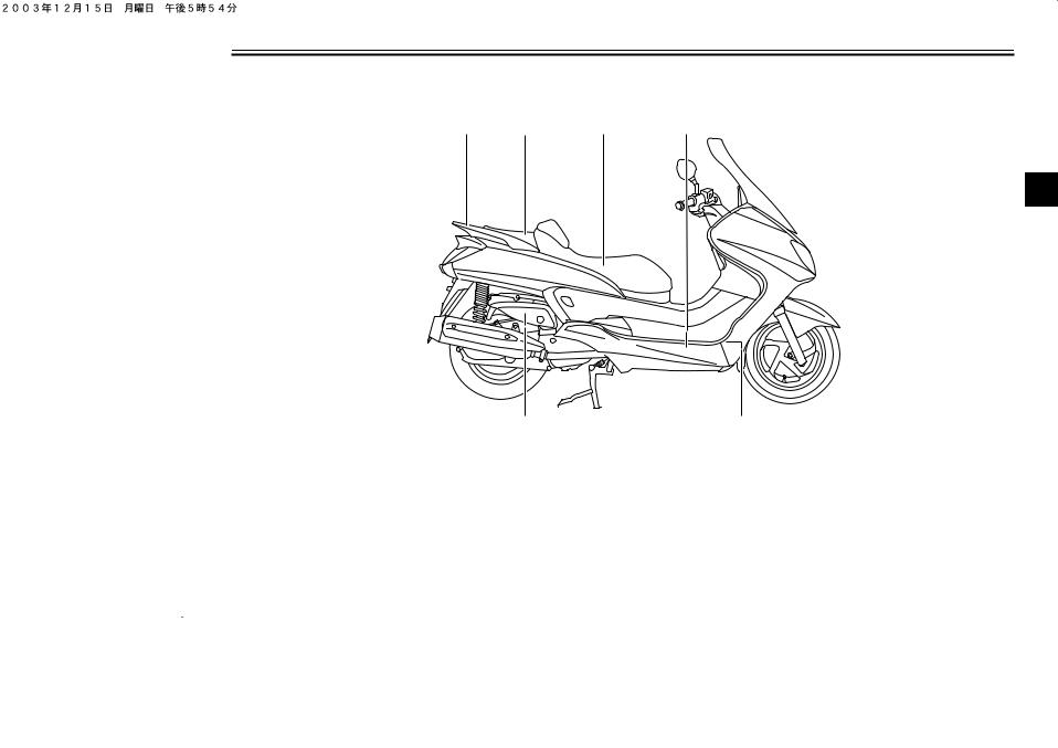
EAU10420
Right view
2
1.Grab bar (page 5-2)
2.Passenger seat (page 3-13)
3.Rider seat (page 3-13)
4.Coolant reservoir (page 6-16)
5.Radiator
6.Air filter element (right) (page 6-18)
2-2
DESCRIPTION
EAU10430
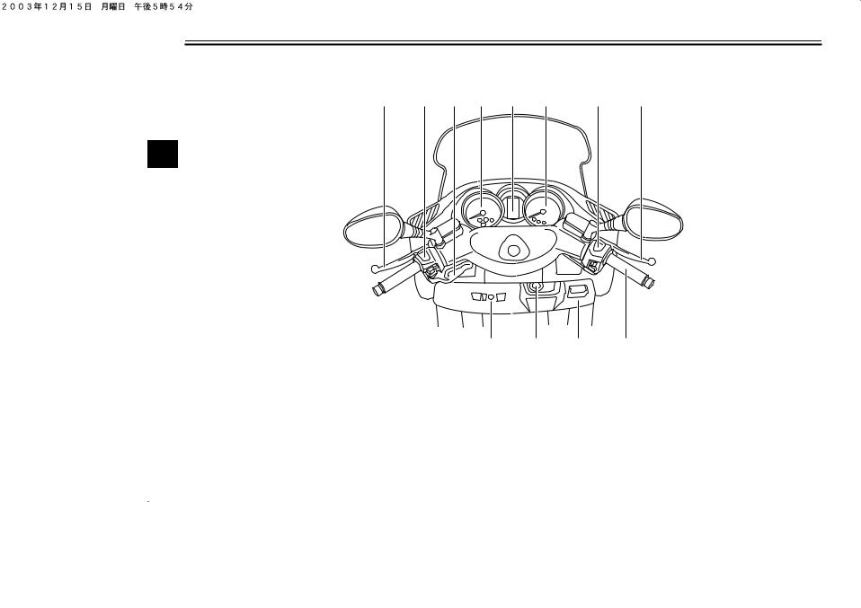
Controls and instruments
|
1 |
2 |
3 |
4 |
5 |
6 |
7 |
8 |
2
|
12 |
11 |
10 |
9 |
|
1. Rear brake lever (page 3-10) |
9. Throttle grip (page 6-20) |
||
|
2. Left handlebar switches (page 3-9) |
10. Front storage compartment B (page 3-15) |
||
|
3. Rear brake lock lever (page 3-11) |
11. Main switch/steering lock (page 3-2) |
||
|
4. Speedometer (page 3-4) |
12. Front storage compartment A (page 3-15) |
||
|
5. Multi-function display (page 3-5) |
|||
|
6. Tachometer (page 3-4) |
|||
|
7. Right handlebar switches (page 3-9) |
|||
|
8. Front brake lever (page 3-10) |
2-3
INSTRUMENT AND CONTROL FUNCTIONS
EAU10972
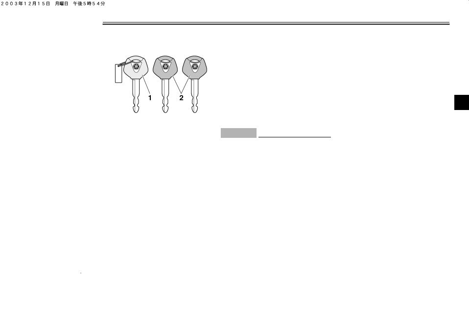
Immobilizer system
1.Code re-registering key (red bow)
2.Standard keys (black bow)
This vehicle is equipped with an immobilizer system to help prevent theft by re-registering codes in the standard keys. This system consists of the following.
●a code re-registering key (with a red bow)
●two standard keys (with a black bow) that can be re-registered with new codes
●a transponder (which is installed in the code re-registering key)
●an immobilizer unit
●an ECU
●an immobilizer system indicator light (See page 3-3.)
The key with the red bow is used to register codes in each standard key. Since re-registering is a difficult process, take the vehicle along with all three keys to a Yamaha dealer to have them re-reg- istered. Do not use the key with the red bow for driving. It should only be used for re-registering the standard keys. Always use a standard key for driving.
ECA11820
CAUTION:
●DO NOT LOSE THE CODE RE-REGISTERING KEY! CONTACT YOUR DEALER IMMEDIATELY IF IT IS LOST! If the code re-registering key is lost, registering new codes in the standard keys is impossible. The standard keys can still be used to start the vehicle, however if code re-registering is required (i.e., if a new standard key is made or all keys are lost) the entire immobilizer system must be replaced. Therefore, it is highly
recommended to use either standard key and keep the code re-registering key in a safe place.
●Do not submerse any key in water.
●Do not expose any key to excessively high temperatures.
● Do not place any key close to 3 magnets (this includes, but not limited to, products such as speakers, etc.).
●Do not place heavy items on any key.
●Do not grind any key or alter its shape.
●Do not disassemble the plastic part of any key.
●Do not put two keys of any immobilizer system on the same key ring.
●Keep the standard keys as well as keys of other immobilizer systems away from this vehicle’s code re-registering key.
●Keep other immobilizer system
3-1
INSTRUMENT AND CONTROL FUNCTIONS
keys away from the main switch as they may cause signal interference.
3
EAU10471
Main switch/steering lock
The main switch/steering lock controls the ignition and lighting systems, and is used to lock the steering.
NOTE:
Be sure to use the standard key (black bow) for regular use of the vehicle. To minimize the risk of losing the code re-registering key (red bow), keep it in a safe place and only use it for code re-registering.
EAU34121
ON
All electrical circuits are supplied with power; the meter lighting, taillight, license plate light and auxiliary lights come on, and the engine can be start-
ed. The key cannot be removed.
NOTE:
The headlights come on automatically when the engine is started and stay on until the key is turned to “OFF” or the sidestand is moved down.
EAU10660
OFF
All electrical systems are off. The key can be removed.
EAU10680
LOCK
The steering is locked, and all electrical systems are off. The key can be removed.
To lock the steering
1.Turn the handlebars all the way to the left.
2.Push the key in from the “OFF” position, and then turn it to “LOCK” while still pushing it.
3.Remove the key.
To unlock the steering
Push the key in, and then turn it to “OFF” while still pushing it.
3-2
INSTRUMENT AND CONTROL FUNCTIONS
EWA10060
 WARNING
Never turn the key to “OFF” or “LOCK” while the vehicle is moving, otherwise the electrical systems will be switched off, which may result in loss of control or an accident. Make sure that the vehicle is stopped before turning the key to “OFF” or “LOCK”.
EAU33491
 (Parking)
The steering is locked, and the taillights and auxiliary lights are on. The hazard light and turn signal lights can be turned on, but all other electrical systems are off. The key can be removed.
The steering must be locked before the key can be turned to “ ”.
”.
ECA11020
CAUTION:
Do not use the parking position for an extended length of time, otherwise the battery may discharge.
EAU11001
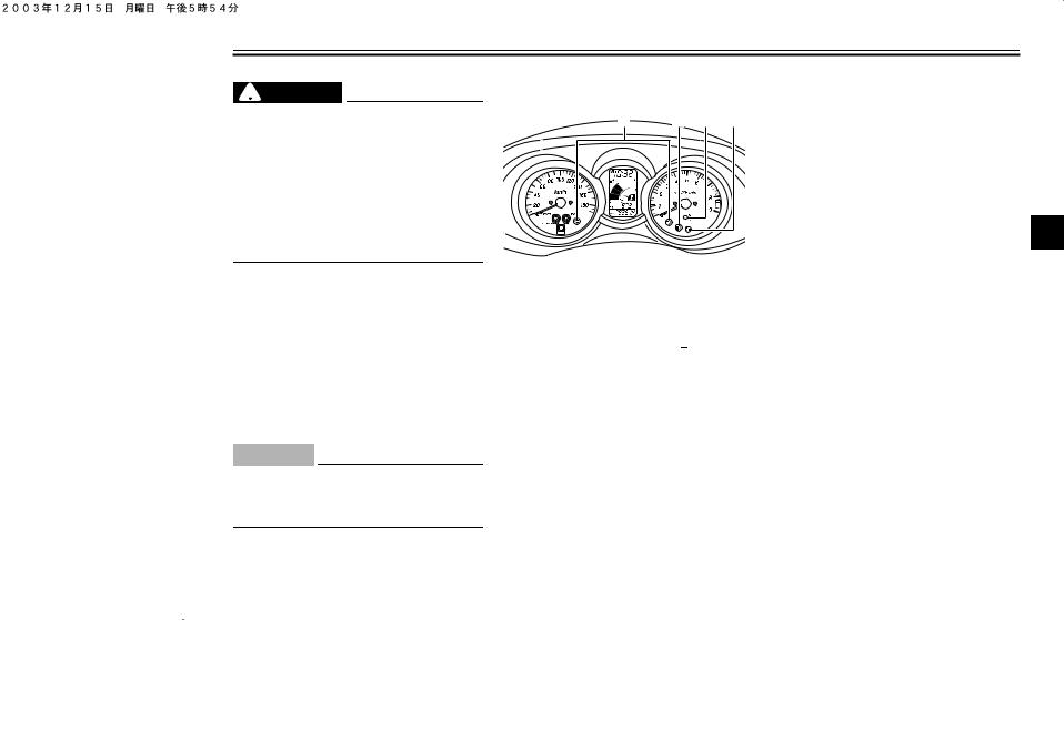
Indicator and warning lights
1.Turn signal indicator lights “ ” and “
  ”
”
2.High beam indicator light “  ”
”
3.Immobilizer system indicator light “  ”
”
4.Engine trouble warning light “  ”
”
EAU11030
Turn signal indicator lights “ ” and
” and
“ ”
”
The corresponding indicator light flashes when the turn signal switch is pushed to the left or right.
EAU11080
High beam indicator light “ ”
”
This indicator light comes on when the high beam of the headlight is switched on.
EAU11480
Engine trouble warning light “  ”
”
This warning light comes on when an electrical circuit monitoring the engine is defective. When this occurs, have a Yamaha dealer check the self-diagno- sis system.
The electrical circuit of the warning light
can be checked by turning the key to 3 “ON”. If the warning light does not come
on for a few seconds, then go off, have a Yamaha dealer check the electrical circuit.
EAU26871
Immobilizer system indicator light
“  ”
”
The electrical circuit of the indicator light can be checked by turning the key to “ON”.
If the indicator light does not come on for a few seconds, then go off, have a Yamaha dealer check the electrical circuit.
When the key is turned to “OFF” and 30 seconds have passed, the indicator light will start flashing indicating the immobilizer system is enabled. After 24
3-3
INSTRUMENT AND CONTROL FUNCTIONS
hours have passed, the indicator light will stop flashing, however the immobilizer system is still enabled.
NOTE:
This model is also equipped with a self-diagnosis device for the immobilizer system. If the immobilizer system is defective, the indicator will start flash-
3ing and the multi-function meter will display an error code when the key is turned to “ON”. (See “Self-diagnosis device” on page 3-5 for details.)
|
EAU11601 |
EAU11872 |
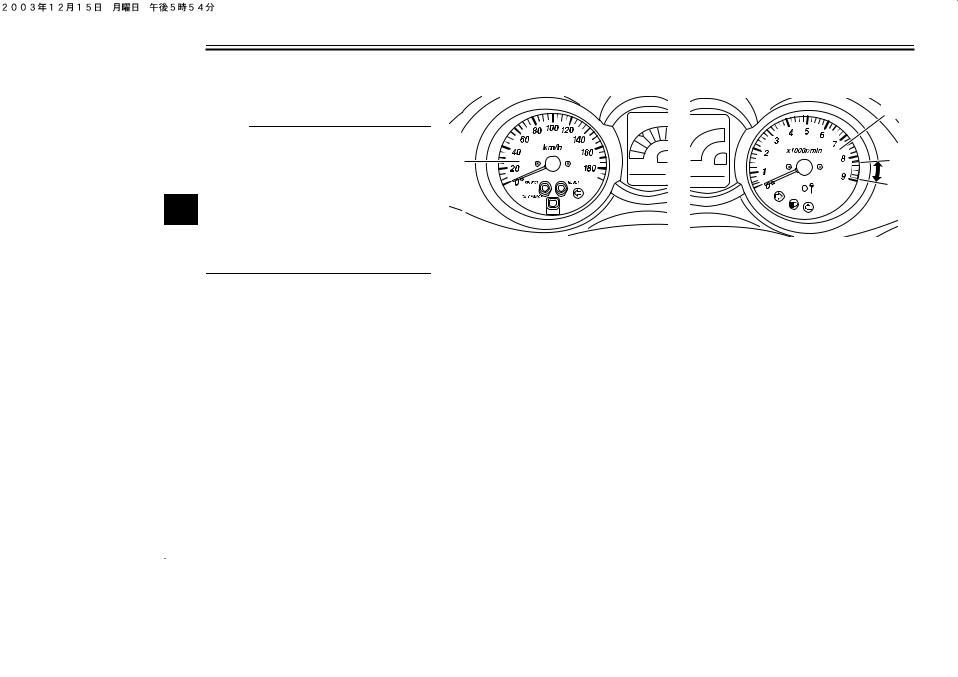
|
Speedometer |
Tachometer |
|
1 |
|
|
1 |
2 |
|
1. Speedometer |
1. Tachometer |
|||
|
The speedometer shows the riding |
2. Tachometer red zone |
|||
|
The electric tachometer allows the rider |
||||
|
speed. |
||||
|
When the key is turned to “ON”, the |
to monitor the engine speed and keep it |
|||
|
speedometer needle will sweep once |
within the ideal power range. |
|||
|
across the speed range and then return |
When the key is turned to “ON”, the ta- |
|||
|
to zero in order to test the electrical cir- |
chometer needle will sweep once |
|||
|
cuit. |
across the r/min range and then return |
|||
|
to zero r/min in order to test the electri- |
||||
|
cal circuit. |
||||
|
ECA10031 |
||||
|
CAUTION: |
||||
|
Do not operate the engine in the ta- |
||||
|
chometer red zone. |
||||
|
Red zone: 8250 r/min and above |
||||
3-4

INSTRUMENT AND CONTROL FUNCTIONS
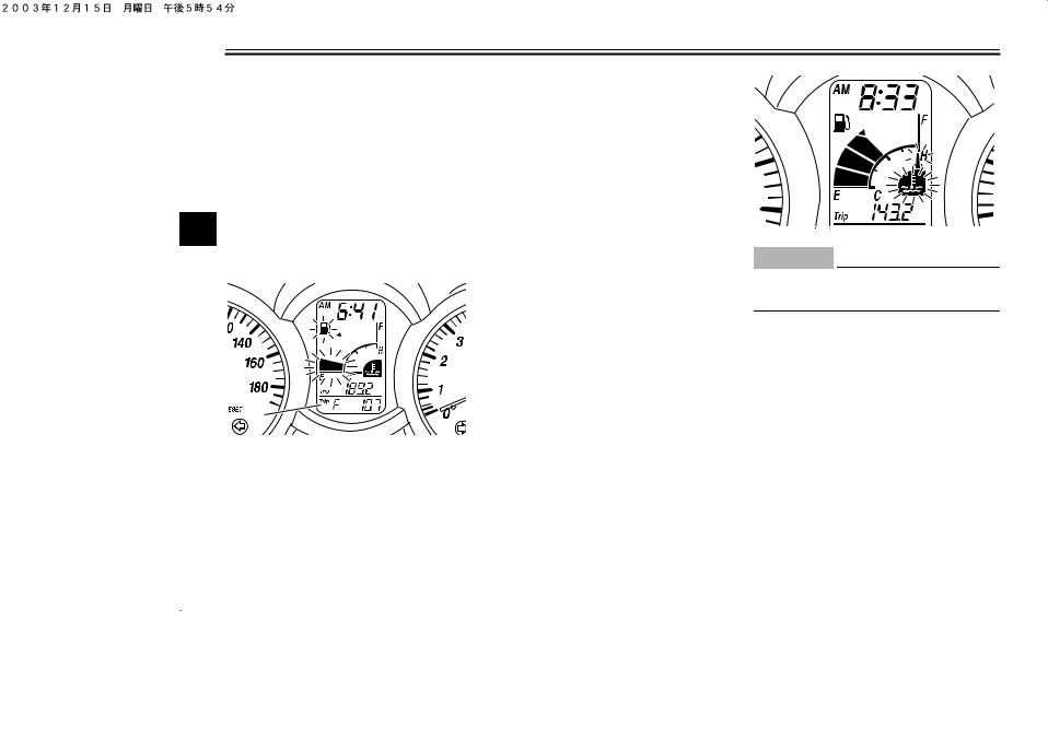
EAU34133
Multi-function display
EWA12311
 WARNING
Be sure to stop the vehicle before making any setting changes to the multi-function display.
1.Clock/ambient temperature display
2.Coolant temperature meter
3.Fuel meter
4.Odometer/tripmeters
5.“SELECT” button
6.“RESET” button
|
1 |
2 |
3 |
4 |
|
1. V-belt replacement indicator “V-BELT” |
2.Fuel level warning symbol  ”
”
3.Coolant temperature symbol “  ”
”
4.Oil change indicator “OIL”
The multi-function display is equipped with the following:
●a fuel meter
●a coolant temperature meter
●an odometer (which shows the total distance traveled)
●two tripmeters (which show the distance traveled since they were last set to zero)
●a fuel reserve tripmeter (which shows the distance traveled since the bottom segment of the fuel meter and fuel level warning sym-
bol started flashing)
●a self-diagnosis device
●a clock
●an ambient temperature display
●an oil change indicator
●a V-belt replacement indicator
NOTE:
● Be sure to turn the key to “ON” be-
fore using the “SELECT” and “RE- 3 SET” buttons.
●When the key is turned to “ON”, all of the display segments of the multi-function display will appear one after the other and then disappear, in order to test the electrical circuit.
Odometer and tripmeter modes
Pushing the “SELECT” button switches the display between the odometer mode “ODO” and the tripmeter modes “TRIP” in the following order:
ODO → TRIP (top) → TRIP (bottom) → ODO
When approximately 2.8 L (0.74 US gal) (0.62 Imp.gal) of fuel remains in the fuel tank, the bottom segment of the
3-5
INSTRUMENT AND CONTROL FUNCTIONS
fuel meter and fuel level warning symbol will start flashing, and the display will automatically change to the fuel reserve tripmeter mode “TRIP F” and start counting the distance traveled from that point. In that case, pushing the “SELECT” button switches the display between the various tripmeter and
3odometer modes in the following order: TRIP F → TRIP (top) → TRIP (bottom) → ODO → TRIP F
1. Fuel reserve tripmeter
To reset a tripmeter, select it by pushing the “SELECT” button, and then push the “RESET” button for at least one second. If you do not reset the fuel reserve tripmeter manually, it will reset
itself automatically and the display will return to the prior mode after refueling and traveling 5 km (3 mi).
Fuel meter
With the key in the “ON” position, the fuel meter indicates the amount of fuel in the fuel tank. The display segments of the fuel meter disappear towards “E” (Empty) as the fuel level decreases. When the fuel level reaches the bottom segment is left near “E”, the fuel level warning symbol and the bottom segment will flash. Refuel as soon as possible.
Coolant temperature meter
With the key in the “ON” position, the coolant temperature meter indicates the temperature of the coolant. The coolant temperature varies with changes in the weather and engine load. If the top segment and coolant temperature symbol flash, stop the vehicle and let the engine cool. (See page 6-37.)
ECA10020
CAUTION:
Do not operate the engine if it is overheated.
Oil change indicator “OIL”
This indicator flashes at the initial 1000 km (600 mi), then at 5000 km (3000 mi) and every 5000 km (3000 mi) thereafter to indicate that the engine oil should be changed.
After changing the engine oil, reset the oil change indicator. (See page 6-12.) If the engine oil is changed before the oil change indicator comes on (i.e. before the periodic oil change interval has been reached), the indicator must be reset after the oil change for the next
3-6
INSTRUMENT AND CONTROL FUNCTIONS
periodic oil change to be indicated at the correct time. (See page 6-12.)
The electrical circuit of the indicator can be checked according to the following procedure.
1.Set the engine stop switch to “ ” and turn the key to “ON”.
2.Check that the indicator comes on for a few seconds and then goes off.
3.If the indicator does not come on, have a Yamaha dealer check the electrical circuit.
NOTE:
The oil change indicator may flash when the engine is revved with the scooter on the centerstand, but this does not indicate a malfunction.
V-belt replacement indicator “V-BELT”
This indicator flashes every 20000 km (12000 mi) when the V-belt needs to be replaced.
The electrical circuit of the indicator can be checked according to the following procedure.
1.Turn the key to “ON” and make
sure that the engine stop switch is set to “ ”.
”.
2.If the indicator does not come on, have a Yamaha dealer check the electrical circuit.
Self-diagnosis device
This model is equipped with a self-diag- nosis device for various electrical circuits.
If any of those circuits are defective, the multi-function display will indicate a two-digit error code (e.g., 12, 13, 14).
If the multi-function display indicates such an error code, note the code number, and then have a Yamaha dealer check the vehicle.
ECA11790
CAUTION:
If the multi-function display indicates an error code, the vehicle should be checked as soon as possible in order to avoid engine damage.
This model is also equipped with a self-diagnosis device for the immobiliz-
er system.
If any of the immobilizer system circuits are defective, the immobilizer system indicator light will flash, and then the multi-function display will indicate a two-digit error code (e.g., 51, 52, 53) when the key is turned to “ON”.
NOTE:
If the multi-function display indicates er- 3 ror code 52, this could be caused by transponder interference. If this error appears, try the following.
1.Use the code re-registering key to start the engine.
NOTE:
Make sure there are no other immobilizer keys close to the main switch, and do not keep more than one immobilizer key on the same key ring! Immobilizer system keys may cause signal interference, which may prevent the engine from starting.
2.If the engine starts, turn it off, and try starting the engine with the standard keys.
3-7
INSTRUMENT AND CONTROL FUNCTIONS
3.If one or both of the standard keys do not start the engine, take the vehicle, the code re-registering key and both standard keys to a Yamaha dealer and have the standard keys re-registered.
If the multi-function display indicates any error codes, note the code number,
3and then have a Yamaha dealer check the vehicle.
Clock mode
To set the clock:
1.Push the “SELECT” button and “RESET” button together for at least two seconds.
2.When the hour digits start flashing, push the “RESET” button to set the hours.
3.Push the “SELECT” button, and the minute digits will start flashing.
4.Push the “RESET” button to set the minutes.
5.Push the “SELECT” button and then release it to start the clock. Pushing the “SELECT” button for at least two seconds switches the
clock display to the ambient temperature display.
Ambient temperature display
This display shows the ambient temperature from –10 °C to 50 °C in 1 °C increments. The temperature displayed may vary from the ambient temperature. Pushing the “SELECT” button for at least two seconds switches the ambient temperature display to the clock display.
NOTE:
●If the ambient temperature falls below –10 °C, a lower temperature than –10 °C will not be displayed.
●If the ambient temperature climbs above 50 °C, a higher temperature than 50 °C will not be displayed.
●The accuracy of the temperature reading may be affected when riding slowly (approximately under 20 km/h) or when stopped at traffic signals, railroad crossings, etc.
EAU12330
Anti-theft alarm (optional)
This model can be equipped with an optional anti-theft alarm by a Yamaha dealer. Contact a Yamaha dealer for more information.
3-8
INSTRUMENT AND CONTROL FUNCTIONS
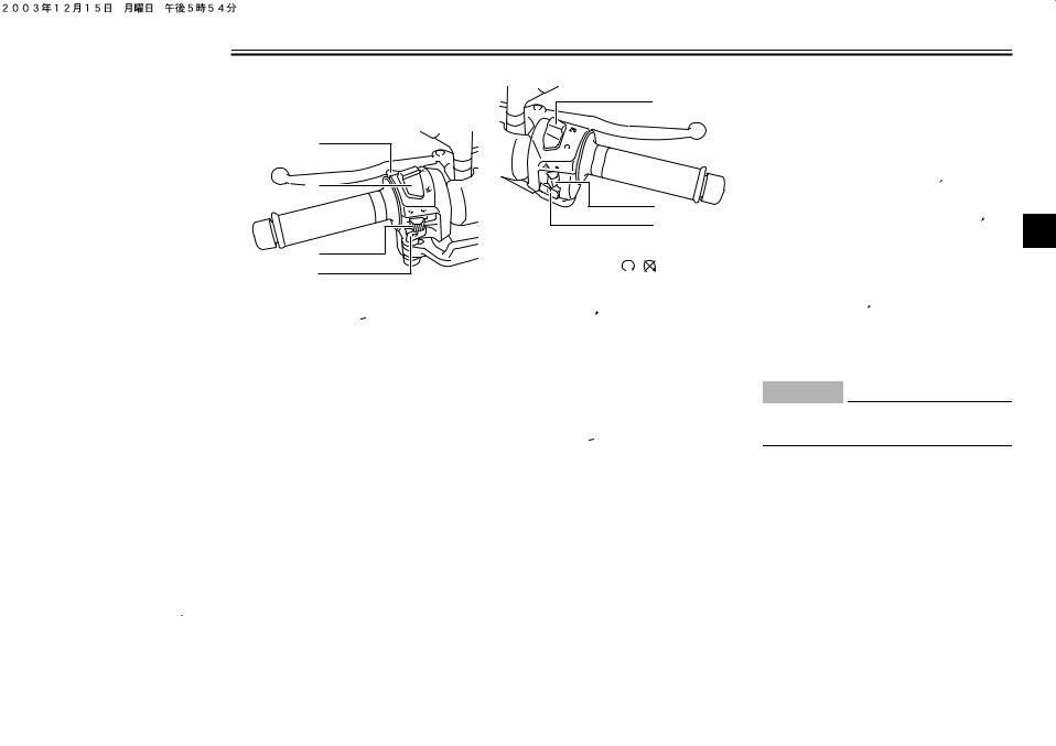
EAU12343 Right
Handlebar switches
1
2
2
3
|
3 |
1. Engine stop switch “ |
/ |
” |
|
|
4 |
||||
1.Pass switch “PASS”
2.Dimmer switch “  /
/ ”
”
3.Turn signal switch “ /
/  ”
”
4.Horn switch “  ”
”
2.Hazard switch “ ”
”
3.Start switch “ ”
”
EAU12360
Pass switch “PASS”
Press this switch to flash the headlight.
EAU12400
Dimmer switch “ /
/ ”
”
Set this switch to “ ” for the high beam and to “
 ” for the low beam.
EAU12460
Turn signal switch “ /
/ ”
”
To signal a right-hand turn, push this switch to “ ”. To signal a left-hand turn, push this switch to “
 ”. When released, the switch returns to the center position. To cancel the turn signal
lights, push the switch in after it has returned to the center position.
EAU12500
Horn switch “  ”
”
Press this switch to sound the horn.
EAU12660
Engine stop switch “ /
/ ”
”
Set this switch to “ ” before starting the engine. Set this switch to “
 ” to
” to
stop the engine in case of an emergen- 3 cy, such as when the vehicle overturns
or when the throttle cable is stuck.
EAU12720
Start switch “ ”
”
With the sidestand up, push this switch while applying the front or rear brake to crank the engine with the starter.
ECA10050
CAUTION:
See page 5-1 for starting instructions prior to starting the engine.
EAU12731
Hazard switch “ ”
”
With the key in the “ON” or “ ” position, use this switch to turn on the hazard light (simultaneous flashing of all turn signal lights).
The hazard light is used in case of an
3-9

INSTRUMENT AND CONTROL FUNCTIONS
emergency or to warn other drivers when your vehicle is stopped where it might be a traffic hazard.
ECA10060
CAUTION:
Do not use the hazard light for an extended length of time, otherwise the battery may discharge.
3
EAU12900
Front brake lever
1
1. Front brake lever
The front brake lever is located on the right handlebar grip. To apply the front brake, pull this lever toward the handlebar grip.
EAU12950
Rear brake lever
1. Rear brake lever
The rear brake lever is located on the left handlebar grip. To apply the rear brake, pull this lever toward the handlebar grip.
3-10
INSTRUMENT AND CONTROL FUNCTIONS
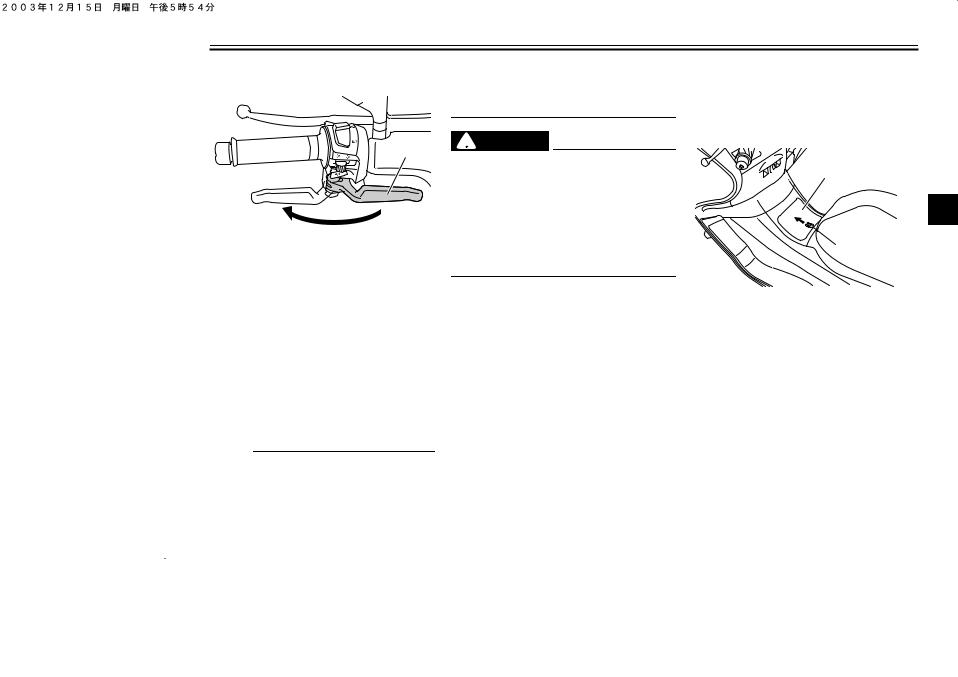
EAU12962
Rear brake lock lever
1. Rear brake lock lever
This vehicle is equipped with a rear brake lock lever to prevent the rear wheel from moving while stopped at traffic signals, railroad crossings, etc.
To lock the rear wheel
Push the rear brake lock lever to the left until it snaps into place.
To unlock the rear wheel
Push the rear brake lock lever back to the original position.
NOTE:
●Be sure to check that the rear wheel does not move when the rear brake lock lever is applied.
●To provide secure locking of the
rear wheel, apply the rear brake lever first before moving the rear brake lock lever to the left.
EWA12361
 WARNING
Never move the rear brake lock lever to the left while the vehicle is moving, otherwise loss of control or an accident may result. Make sure that the vehicle is stopped before moving the rear brake lock lever to the left.
3-11
EAU13161
Fuel tank cap
To open the fuel tank cap
1.Open the lid by sliding the lever forward, and then pull the lever up.
1
3
 2
2
1.Lid
2.Opening lever
2.Insert the key into the lock and turn it clockwise. The lock will be released and the fuel tank cap can be removed.
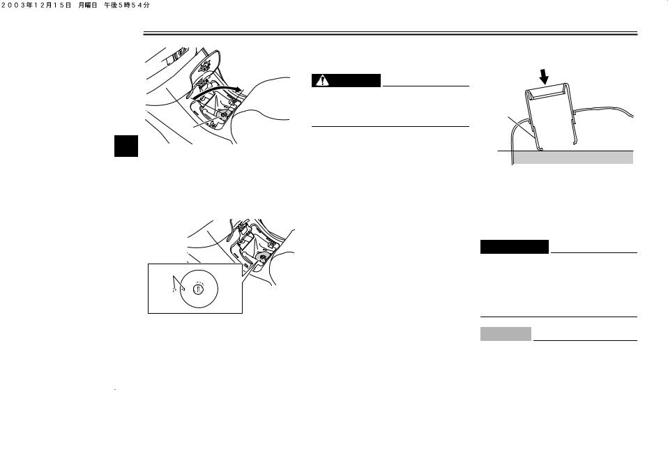
|
INSTRUMENT AND CONTROL FUNCTIONS |
||
|
move it. |
EAU13210 |
|
|
3. Close the lid. |
Fuel |
|
|
EWA11120 |
||
|
WARNING |
||
|
Be sure that the fuel tank cap is |
||
|
properly installed and locked before |
1 |
|
|
riding the scooter. |
||
|
1 |
||
|
3 |
2 |
|
|
1. Fuel tank cap |
||
To install the fuel tank cap
1.Align the match marks, insert the fuel tank cap into the tank opening, and then push down on the cap.
1
1.Fuel tank filler tube
2.Fuel level
Make sure that there is sufficient fuel in the tank. Fill the fuel tank to the bottom of the filler tube as shown.
EWA10880
 WARNING
●Do not overfill the fuel tank, otherwise it may overflow when the fuel warms up and expands.
●Avoid spilling fuel on the hot engine.
1.Match marks
2.Turn the key counterclockwise to the original position, and then re-
ECA10070
CAUTION:
Immediately wipe off spilled fuel with a clean, dry, soft cloth, since
3-12
 Loading…