
- Manuals
- Brands
- Yamaha Manuals
- Motorcycle
- FAZER FZS1000
- Owner’s manual
-
Contents
-
Table of Contents
-
Troubleshooting
-
Bookmarks
Quick Links
OWNER’S MANUAL
FZS1000
FZS1000S
1C2-28199-E0
Related Manuals for Yamaha FAZER FZS1000
Summary of Contents for Yamaha FAZER FZS1000
-
Page 1
OWNER’S MANUAL FZS1000 FZS1000S 1C2-28199-E0… -
Page 3
In addition, the many tips given in this manual will help keep your motorcycle in the best possible con- dition. If you have any further questions, do not hesitate to contact your Yamaha dealer. The Yamaha team wishes you many safe and pleasant rides. So, remember to put safety first! -
Page 4: Important Manual Information
This manual should be considered a permanent part of this motorcycle and should remain with it even if the motorcycle is subsequently sold. Yamaha continually seeks advancements in product design and quality. Therefore, while this manual contains the most current product information available at the time of printing, there may be minor discrepancies between your motorcycle and this manual.
-
Page 5
IMPORTANT MANUAL INFORMATION EAU10200 FZS1000/FZS1000S OWNER’S MANUAL ©2003 by Yamaha Motor Co., Ltd. 1st edition, May 2003 All rights reserved. Any reprinting or unauthorized use without the written permission of Yamaha Motor Co., Ltd. is expressly prohibited. Printed in Japan. -
Page 6: Table Of Contents
TABLE OF CONTENTS SAFETY INFORMATION ….1-1 EXUP system ……. 3-16 Adjusting the throttle cable Sidestand ……..3-17 free play ……..6-17 DESCRIPTION ……..2-1 Ignition circuit cut-off system ..3-17 Adjusting the valve clearance ..6-17 Left view ……….2-1 Tires ……….6-17 Right view ……..2-2 PRE-OPERATION CHECKS …..
-
Page 7
TABLE OF CONTENTS Battery ……….6-30 Replacing the fuses ……6-31 Replacing a headlight bulb …6-32 Replacing a tail/brake light bulb …6-33 Replacing a turn signal light bulb ………..6-34 Front wheel ……..6-34 Rear wheel ……..6-35 Troubleshooting ……6-37 Troubleshooting charts ….6-38 MOTORCYCLE CARE AND STORAGE ……….7-1 Care ……….7-1 Storage ………..7-3… -
Page 8: Safety Information
SAFETY INFORMATION EAU10270 AND/OR WHEN MADE NECES- • Ride where other motorists can SARY BY MECHANICAL CONDI- see you. Avoid riding in another MOTORCYCLES SINGLE TIONS. motorist’s blind spot. TRACK VEHICLES. THEIR SAFE USE Many accidents involve inexperi- AND OPERATION ARE DEPENDENT Safe riding enced operators.
-
Page 9
Modifications made to this motorcycle other motorists can see you. the single most critical factor in the pre- not approved by Yamaha, or the re- The posture of the operator and vention or reduction of head injuries. moval of original equipment, may ren- passenger is important for proper Always wear an approved helmet. -
Page 10
Since Yamaha cannot should be kept to a minimum. 189 kg (417 lb). When loading within test all other accessories that may be •… -
Page 11
SAFETY INFORMATION Gasoline and exhaust gas • Do not park the motorcycle on a GASOLINE IS HIGHLY FLAMMA- slope or soft ground, otherwise it BLE: may fall over. • Always turn the engine off when • Do not park the motorcycle near refueling. -
Page 12: Description
DESCRIPTION EAU10410 Left view 1. Front fork compression damping force adjusting screw (page 3-13) 11.Shock absorber assembly rebound damping force adjusting knob (page 3-14) 2. Front fork rebound damping force adjusting screw (page 3-13) 12.Shift pedal (page 3-8) 3. Front fork spring preload adjusting bolt (page 3-13) 4.
-
Page 13: Right View
DESCRIPTION EAU10420 Right view 1. Owner’s tool kit (page 6-1) 2. Rear brake fluid reservoir (page 6-23) 3. Battery (page 6-30) 4. Front brake fluid reservoir (page 6-23) 5. Radiator cap (page 6-11) 6. Engine oil filter cartridge (page 6-8) 7.
-
Page 14: Controls And Instruments
DESCRIPTION EAU10430 Controls and instruments 1. Clutch lever (page 3-7) 2. Left handlebar switches (page 3-6) 3. Starter (choke) lever (page 3-11) 4. Speedometer unit (page 3-3) 5. Main switch/steering lock (page 3-1) 6. Tachometer unit (page 3-4) 7. Fuel gauge (page 3-5) 8.
-
Page 15: Instrument And Control Functions
INSTRUMENT AND CONTROL FUNCTIONS EAU10460 EAU10660 To unlock the steering Main switch/steering lock All electrical systems are off. The key can be removed. EAU10680 LOCK The steering is locked, and all electrical systems are off. The key can be re- moved.
-
Page 16: Indicator And Warning Lights
3. High beam indicator light “ ” for a few seconds, then go off, have a 4. Oil level warning light “ ” Yamaha dealer check the electrical cir- 5. Right turn signal indicator light “ ” cuit. 6. Coolant temperature warning light “…
-
Page 17: Speedometer Unit
“ON”. If the warning light does not come on for a few seconds, then go off, have a 1. Speedometer Yamaha dealer check the electrical cir- 2. Odometer/tripmeter cuit. 3. “SELECT” button 4. “RESET” button…
-
Page 18: Tachometer Unit
INSTRUMENT AND CONTROL FUNCTIONS be traveled on a full tank of fuel. This in- EAU11891 To set the clock Tachometer unit formation will enable you to plan future 1. Push both the “SELECT” and “RE- fuel stops. SET” buttons for at least two sec- onds.
-
Page 19: Self-Diagnosis Devices
EAU12110 Self-diagnosis devices Fuel gauge code, note the circuit-specific number This model is equipped with a self-diag- of r/min, and then have a Yamaha deal- nosis device for the following electrical er check the vehicle. circuits: ECA10040 throttle position sensor…
-
Page 20: Anti-Theft Alarm (Optional)
EAU12341 Right Anti-theft alarm (optional) Handlebar switches This model can be equipped with an Left optional anti-theft alarm by a Yamaha dealer. Contact a Yamaha dealer for more information. 1. Engine stop switch “ ” 2. Start switch “ ”…
-
Page 21: Clutch Lever
INSTRUMENT AND CONTROL FUNCTIONS position. To cancel the turn signal EAU12730 EAU12820 Hazard switch “ ” Clutch lever lights, push the switch in after it has re- With the key in the “ON” or “ ” posi- turned to the center position. tion, use this switch to turn on the haz- ard light (simultaneous flashing of all EAU12500…
-
Page 22: Shift Pedal
INSTRUMENT AND CONTROL FUNCTIONS EAU12870 EAU12930 EAU12941 Shift pedal Brake lever Brake pedal The brake lever is located at the right handlebar grip. To apply the front brake, pull the lever toward the handle- bar grip. 1. Shift pedal 1. Brake pedal The shift pedal is located on the left The brake pedal is on the right side of side of the engine and is used in com-…
-
Page 23: Fuel Tank Cap
INSTRUMENT AND CONTROL FUNCTIONS EAU13070 EAU13210 Fuel tank cap NOTE: Fuel The fuel tank cap cannot be closed un- less the key is in the lock. In addition, the key cannot be removed if the cap is not properly closed and locked. EWA11090 WARNING Make sure that the fuel tank cap is…
-
Page 24: Fuel Tank Breather Hose
Your Yamaha engine has been de- signed to use regular unleaded gaso- line with a research octane number of 91 or higher. If knocking (or pinging) oc-…
-
Page 25: Starter (Choke) Lever
INSTRUMENT AND CONTROL FUNCTIONS EAU13590 EAU13940 Starter (choke) lever “ ” Seat To remove the seat 1. Insert the key into the seat lock, and then turn it clockwise. 1. Projection 2. Seat holder 1. Starter (choke) lever “ ” 2.
-
Page 26: Helmet Holder
This storage compartment is designed When storing the owner’s manual or To open the helmet holder, insert the to hold an optional genuine Yamaha U- other documents in the storage com- key into the seat lock, and then turn the LOCK.
-
Page 27: Adjusting The Front Fork
INSTRUMENT AND CONTROL FUNCTIONS EAU14750 load thereby soften Rebound damping force Adjusting the front fork suspension, turn the adjusting bolt on This front fork is equipped with spring each fork leg in direction (b). preload adjusting bolts, rebound damp- NOTE: ing force adjusting screws and com- Align the appropriate groove on the ad- pression…
-
Page 28: Adjusting The Shock Absorber Assembly
INSTRUMENT AND CONTROL FUNCTIONS Compression damping force ECA10100 EAU15041 Adjusting the shock absorber CAUTION: assembly Never attempt to turn an adjusting This shock absorber assembly is mechanism beyond the maximum or equipped with a spring preload adjust- minimum settings. ing ring, a rebound damping force ad- justing knob and a compression NOTE: damping force adjusting screw.
-
Page 29
INSTRUMENT AND CONTROL FUNCTIONS To increase the spring preload and Rebound damping force Compression damping force thereby harden the suspension, turn the adjusting ring in direction (a). To de- crease the spring preload and thereby soften the suspension, turn the adjust- ing ring in direction (b). -
Page 30: Exup System
NOTE: EXUP system sorber to an open flame or other Although the total number of clicks of a This model is equipped with Yamaha’s high heat sources, otherwise it damping force adjusting mechanism EXUP (EXhaust Ultimate Power valve) may explode due to excessive may not exactly match the above spec- system.
-
Page 31: Sidestand
INSTRUMENT AND CONTROL FUNCTIONS EAU15300 below and have a Yamaha dealer re- EAU15321 Sidestand Ignition circuit cut-off system pair it if it does not function proper- The sidestand is located on the left side The ignition circuit cut-off system (com- of the frame.
-
Page 32
5. Push the start switch. Does the engine start? The neutral switch may be defective. The motorcycle should not be ridden until checked by a Yamaha dealer. With the engine still running: 6. Move the sidestand up. 7. Keep the clutch lever pulled. -
Page 33: Pre-Operation Checks
PRE-OPERATION CHECKS EAU15591 The condition of a vehicle is the owner’s responsibility. Vital components can start to deteriorate quickly and unexpectedly, even if the vehicle remains unused (for example, as a result of exposure to the elements). Any damage, fluid leakage or loss of tire air pressure could have serious consequences.
-
Page 34: Pre-Operation Check List
• If necessary, add recommended coolant to specified level. 6-11 • Check cooling system for leakage. • Check operation. • If soft or spongy, have Yamaha dealer bleed hydraulic system. • Check brake pads for wear. Front brake • Replace if necessary.
-
Page 35
• Make sure that operation is smooth. • Check cable free play. Throttle grip 6-17, 6-26 • If necessary, have Yamaha dealer adjust cable free play and lubricate cable and grip housing. • Make sure that operation is smooth. Control cables 6-26 •… -
Page 36: Operation And Important Riding Points
EWA10290 Yamaha dealer check the electrical cir- WARNING Never start the engine or oper- cuit. ate it in a closed area for any Before…
-
Page 37
Yamaha dealer check the with sufficient engine oil, have a electrical circuit. Yamaha dealer check the elec- trical circuit. -
Page 38: Starting A Warm Engine
OPERATION AND IMPORTANT RIDING POINTS EAU16640 EAU16671 ECA10260 Starting a warm engine Shifting CAUTION: Follow the same procedure as for start- Even with the transmission in ing a cold engine with the exception the neutral position, do not that the starter (choke) is not required coast for long periods of time when the engine is warm.
-
Page 39: Tips For Reducing Fuel Consumption
OPERATION AND IMPORTANT RIDING POINTS EAU16800 EAU16841 Shift up points: Tips for reducing fuel Engine break-in 1st → 2nd: 20 km/h (12 mi/h) consumption There is never a more important period 2nd → 3rd: 30 km/h (19 mi/h) in the life of your engine than the period 3rd →…
-
Page 40: Parking
Do not park on a slope or on soft the tachometer red zone. ground, otherwise the vehicle If any engine trouble should oc- may overturn. cur during the engine break-in period, immediately have a Yamaha dealer check the vehi- cle.
-
Page 41: Periodic Maintenance And Minor Repair
Yamaha dealer certain maintenance work correctly. do it for you. NOTE: If you do not have the tools or experi- ence required for a particular job, have a Yamaha dealer perform it for you.
-
Page 42: Periodic Maintenance And Lubrication Chart
The annual checks must be performed every year, except if a kilometer-based maintenance is performed in- stead. From 50,000 km, repeat the maintenance intervals starting from 10,000 km. Items marked with an asterisk should be performed by a Yamaha dealer as they require special tools, data and technical skills. ODOMETER READING (× 1,000 km)
-
Page 43
PERIODIC MAINTENANCE AND MINOR REPAIR ODOMETER READING (× 1,000 km) ANNUAL ITEM CHECK OR MAINTENANCE JOB CHECK √ √ √ √ √ • Check for cracks or damage. 9 * Brake hoses • Replace. Every 4 years √ √ √ √… -
Page 44
PERIODIC MAINTENANCE AND MINOR REPAIR ODOMETER READING (× 1,000 km) ANNUAL ITEM CHECK OR MAINTENANCE JOB CHECK • Check starter (choke) operation. √ √ √ √ √ √ 22 * Carburetors • Adjust engine idling speed and synchronization. • Change. √… -
Page 45
PERIODIC MAINTENANCE AND MINOR REPAIR Hydraulic brake service • Regularly check and, if necessary, correct the brake fluid level. • Every two years replace the internal components of the brake master cylinders and calipers, and change the brake fluid. • Replace the brake hoses every four years and if cracked or damaged. -
Page 46: Removing And Installing Panels
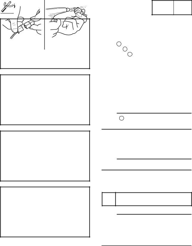
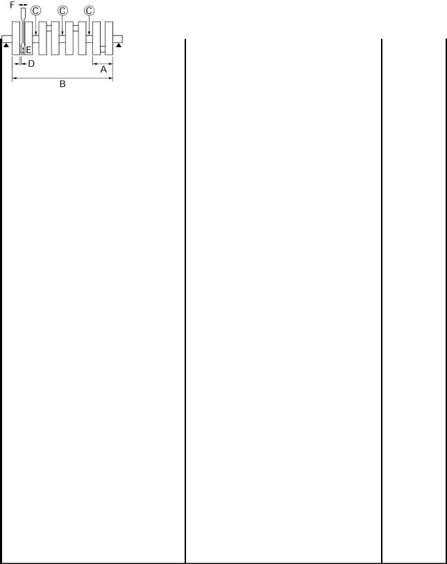
PERIODIC MAINTENANCE AND MINOR REPAIR EAU18770 The panels shown above need to be re- Removing and installing moved to perform some of the mainte- panels nance jobs described in this chapter. Refer to this section each time a panel needs to be removed and installed. EAU19292 Panels A and C To remove one of the panels…
-
Page 47: Checking The Spark Plugs
Do not attempt to diagnose such 1. Spark plug cap problems yourself. Instead, have a 2. Remove the spark plug as shown, Yamaha dealer check the vehicle. with the spark plug wrench includ- ed in the owner’s tool kit.
-
Page 48: Engine Oil And Oil Filter Cartridge
PERIODIC MAINTENANCE AND MINOR REPAIR 3. Check each spark plug for elec- 2. Clean the surface of the spark plug EAU19890 Engine oil and oil filter trode erosion and excessive car- gasket and its mating surface, and cartridge bon or other deposits, and replace then wipe off any grime from the The engine oil level should be checked it if necessary.
-
Page 49: To Change Engine Oil
2. Oil filter cartridge NOTE: An oil filter wrench is available at a 1. Engine oil filler cap Yamaha dealer. 2. Engine oil level check window 1. Engine oil drain bolt 3. Maximum level mark 5. Apply a thin coat of engine oil to 4.
-
Page 50
PERIODIC MAINTENANCE AND MINOR REPAIR Recommended engine oil: See page 8-1. Oil quantity: Without oil filter cartridge replace- ment: 2.80 L (2.96 US qt) (2.46 Imp.qt) With oil filter cartridge replacement: 3.00 L (3.17 US qt) (2.64 Imp.qt) ECA11620 CAUTION: 1. -
Page 51: Coolant
If the oil level warning light flickers EAU20101 or remains on, immediately turn the To check the coolant level engine off and have a Yamaha dealer 1. Place the vehicle on the center- 1. Coolant reservoir check the vehicle. stand.
-
Page 52
2. Remove panels A and B. (See If water has been added to the page 6-6.) coolant, have a Yamaha dealer 3. Place a container under the engine check the antifreeze content of to collect the used coolant. -
Page 53
If ant as soon as possible, other- 7 Nm (0.7 m·kgf, 5 ft·lbf) coolant is leaking, have a Yamaha wise the engine may not be sufficiently cooled and the cool- dealer check the cooling system. -
Page 54: Cleaning The Air Filter Element
PERIODIC MAINTENANCE AND MINOR REPAIR EAU20681 Do not tilt or pull the fuel tank Cleaning the air filter element too much, otherwise the fuel The air filter element should be cleaned hoses may come loose, which at the intervals specified in the periodic could cause fuel leakage.
-
Page 55
Before installing the fuel tank, make sure that the fuel hoses are not damaged. If any fuel hose is damaged, do not start the engine but have a Yamaha dealer replace the hose, other- wise fuel may leak. Make sure that the fuel hoses are properly connected and 1. -
Page 56: Adjusting The Carburetors
Therefore, most carbu- checked and, if necessary, adjusted as retor adjustments should be left to a follows at the intervals specified in the Yamaha dealer, who has the neces- periodic maintenance and lubrication sary professional knowledge and expe- chart.
-
Page 57: Adjusting The Throttle Cable Free Play
Yamaha dealer at the intervals specified in the periodic Tire air pressure maintenance and lubrication chart. The tire air pressure should be checked and, if necessary, adjusted before each ride.
-
Page 58
189 kg (417 lb) glass fragments in it, or if the sidewall is weight evenly on both sides. * Total weight of rider, passenger, car- cracked, have a Yamaha dealer re- Adjust the suspension and tire go and accessories place the tire immediately. -
Page 59
PERIODIC MAINTENANCE AND MINOR REPAIR EWA10470 This motorcycle is equipped with cast Front tire: WARNING wheels and tubeless tires with valves. Size: Have a Yamaha dealer replace EWA10480 120/70 ZR17M/C (58W) WARNING Manufacturer/model: excessively worn tires. Besides METZELER/MEZ4Y FRONT being illegal, operating the vehi-… -
Page 60: Cast Wheels
If any damage is found, have a Yamaha dealer re- place the wheel. Do not attempt even the smallest repair to the wheel. A deformed or cracked 1.
-
Page 61: Adjusting The Brake Pedal Position
Yamaha dealer check the internal clutch mechanism. 1. Distance between brake pedal and footrest The top of the brake pedal should be positioned approximately 43.0 mm (1.69 in) below the top of the footrest as…
-
Page 62: Adjusting The Rear Brake Light Switch
If a brake pad has worn to the point that the wear indicator groove has almost disappeared, have a Yamaha dealer replace the brake pads as a set. 1. Rear brake light switch 2. Rear brake light switch adjusting nut 1.
-
Page 63: Checking The Brake Fluid Level
However, if the Use only the recommended quality brake fluid level goes down sud- 1. Minimum level mark brake fluid, otherwise the rubber denly, have a Yamaha dealer Rear brake seals may deteriorate, causing check the cause. leakage and poor braking perfor- mance.
-
Page 64: Changing The Brake Fluid
EAU22730 EAU22760 Changing the brake fluid Drive chain slack Have a Yamaha dealer change the The drive chain slack should be brake fluid at the intervals specified in checked before each ride and adjusted the NOTE after the periodic mainte- if necessary.
-
Page 65: Lubricating The Drive Chain
PERIODIC MAINTENANCE AND MINOR REPAIR 3. Tighten the locknuts, and then EAU23020 NOTE: Lubricating the drive chain tighten the axle nut to the specified Using the alignment marks on each The drive chain must be cleaned and torque. side of the swingarm, make sure that lubricated at the intervals specified in both chain pullers are in the same posi- the periodic maintenance and lubrica-…
-
Page 66: Checking And Lubricating The Cables
If a cable is damaged periodic maintenance chart. or does not move smoothly, have a Yamaha dealer check or replace it. Recommended lubricant: Engine oil EWA10720 WARNING…
-
Page 67: Checking And Lubricating The Brake And Shift Pedals
Lithium-soap-based grease (all-pur- Lithium-soap-based grease (all-pur- WARNING pose grease) pose grease) If the centerstand or sidestand does not move up and down smoothly, have a Yamaha dealer check or re- pair it. Recommended lubricant: Lithium-soap-based grease (all-pur- pose grease) 6-27…
-
Page 68: Lubricating The Rear Suspension
If any damage is found or the front Check the inner tubes for scratches, fork does not operate smoothly, damage and excessive oil leakage. have a Yamaha dealer check or re- pair it. To check the operation 1. Place the vehicle on a level sur- face and hold it in an upright posi- tion.
-
Page 69: Checking The Steering
2. Hold the lower ends of the front fork legs and try to move them for- ward and backward. If any free play can be felt, have a Yamaha dealer check or repair the steering. 6-29…
-
Page 70: Battery
Electrolyte is poisonous and To charge the battery To charge a sealed-type (MF) dangerous since it contains sul- Have a Yamaha dealer charge the bat- battery, a special (constant-volt- furic acid, which causes severe tery as soon as possible if it seems to age) battery charger is required.
-
Page 71: Replacing The Fuses
EAU23622 2. Remove the blown fuse, and then 4. If the fuse immediately blows Replacing the fuses install a new fuse of the specified again, have a Yamaha dealer amperage. check the electrical system. Specified fuses: Main fuse: 30.0 A Headlight fuse: 20.0 A…
-
Page 72: Replacing A Headlight Bulb
PERIODIC MAINTENANCE AND MINOR REPAIR EAU23730 Headlight bulb Replacing a headlight bulb Do not touch the glass part of This model is equipped with two quartz the headlight bulb to keep it free bulb headlights. If a headlight bulb from oil, otherwise the transpar- burns out, replace it as follows.
-
Page 73: Replacing A Tail/Brake Light Bulb
Replacing a tail/brake light and then connect the coupler. bulb 6. Install the panel. 1. Remove the seat. (See page 7. Have a Yamaha dealer adjust the 3-11.) headlight beam if necessary. 2. Remove the tail/brake light bulb cover. 1. Tail/brake light bulb socket 4.
-
Page 74: Replacing A Turn Signal Light Bulb
To remove the front wheel by removing the screw. EWA10820 WARNING It is advisable to have a Yamaha dealer service the wheel. Securely support the motor- cycle so that there is no danger of it falling over.
-
Page 75: Rear Wheel
2. Insert the wheel axle. EWA10820 3. Lower the front wheel so that it is WARNING on the ground. It is advisable to have a Yamaha 4. Install the brake calipers by install- dealer service the wheel. ing the bolts. Securely support the motor-…
-
Page 76
PERIODIC MAINTENANCE AND MINOR REPAIR 3. Disconnect the brake torque rod 6. Turn the drive chain slack adjust- EAU25841 To install the rear wheel from the brake caliper by removing ing bolts fully in direction (a). 1. Place the wheel and the brake cal- the nut and the bolt. -
Page 77: Troubleshooting
However, should your motorcycle require any repair, take it to a Yamaha Tightening torques: dealer, whose skilled technicians have Axle nut: 150 Nm (15.0 m·kgf, 108 ft·lbf)
-
Page 78: Troubleshooting Charts
Remove the spark plugs and check the electrodes. The engine does not start. Have a Yamaha dealer check the vehicle. Check the battery. 4. Battery The engine turns over The battery is good.
-
Page 79
Start the engine. If the engine overheats again, have a The coolant level Yamaha dealer check and repair the cooling system. is OK. NOTE: If coolant is not available, tap water can be temporarily used instead, provided that it is changed to the recommended coolant as soon as possible. -
Page 80: Motorcycle Care And Storage
MOTORCYCLE CARE AND STORAGE EAU26010 ucts onto seals, gaskets, sprock- cleaning products, solvent or Care ets, the drive chain and wheel thinner, fuel (gasoline), rust re- While the open design of a motorcycle axles. Always rinse the dirt and de- movers or inhibitors, brake flu- reveals the attractiveness of the tech- greaser off with water.
-
Page 81
MOTORCYCLE CARE AND STORAGE After normal use ECA10790 5. Use spray oil as a universal clean- CAUTION: Remove dirt with warm water, a mild er to remove any remaining dirt. detergent, and a soft, clean sponge, 6. Touch up minor paint damage Do not use warm water since it in- and then rinse thoroughly with clean caused by stones, etc. -
Page 82: Storage
CAUTION: NOTE: fuel from deteriorating. Storing the motorcycle in a Consult a Yamaha dealer for advice on 5. Perform the following steps to pro- poorly ventilated room or cover- what products to use. tect the cylinders, piston rings, etc.
-
Page 83
MOTORCYCLE CARE AND STORAGE EWA10950 °C (90 °F)]. For more information WARNING on storing the battery, see page To prevent damage or injury from 6-30. sparking, make sure to ground the NOTE: spark plug electrodes while turning Make any necessary repairs before the engine over. -
Page 84: Specifications
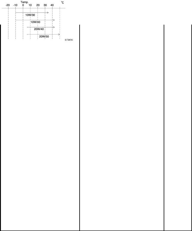
SPECIFICATIONS Dimensions: Engine oil: Fuel: Overall length: Type: Recommended fuel: 2125 mm (83.7 in) SAE10W30 or SAE10W40 or SAE15W40 Regular unleaded gasoline only Overall width: or SAE20W40 or SAE20W50 Fuel tank capacity: 765 mm (30.1 in) 21.0 L (5.55 US gal) (4.62 Imp.gal) Overall height: Fuel reserve amount: -20 -10…
-
Page 85
SPECIFICATIONS Operation: Manufacturer/model: Rim size: Left foot operation METZELER/MEZ4Y 17M/C x MT5.50 Gear ratio: Loading: Front brake: 1st: Maximum load: Type: 35/14 (2.500) 189 kg (417 lb) Dual disc brake 2nd: (Total weight of rider, passenger, cargo and Operation: 35/19 (1.842) accessories) Right hand operation 3rd:… -
Page 86
SPECIFICATIONS Charging system: Coolant temperature indicator light: A.C. magneto Battery: Fuses: Model: Main fuse: GT14B-4 30.0 A Voltage, capacity: Headlight fuse: 12 V, 12.0 Ah 20.0 A Headlight: Signaling system fuse: 20.0 A Bulb type: Ignition fuse: Halogen bulb 20.0 A Bulb voltage, wattage x quantity: Radiator fan fuse: Headlight:… -
Page 87: Consumer Information
Record the key identification number, vehicle identification number and mod- el label information in the spaces pro- vided below for assistance when ordering spare parts from a Yamaha dealer or for reference in case the vehi- cle is stolen. KEY IDENTIFICATION NUMBER: 1.
-
Page 88
1. Model label The model label is affixed to the frame under the seat. (See page 3-11.) Record the information on this label in the space provided. This information will be needed when ordering spare parts from a Yamaha dealer. -
Page 89
INDEX EXUP system ……..3-16 Parking………… 5-5 Part locations ………. 2-1 Air filter element, cleaning ….6-14 Pass switch……….3-6 Anti-theft alarm (optional) ……. 3-6 Front and rear brake pads, checking ..6-22 Periodic maintenance and Front fork, adjusting ……3-13 lubrication chart ……..6-2 Front fork, checking…….6-28 Battery ………. -
Page 90
INDEX Troubleshooting ……..6-37 Troubleshooting charts ……6-38 Turn signal indicator lights …… 3-2 Turn signal light bulb, replacing …. 6-34 Turn signal switch ……..3-6 Valve clearance, adjusting ….6-17 Vehicle identification number ….9-1 Wheel bearings, checking….. 6-29 Wheel (front) ……… -
Page 92
YAMAHA MOTOR CO., LTD. PRINTED ON RECYCLED PAPER PRINTED IN JAPAN 2003.06-0.4×1 CR…
![]()
EAS00000
FZS1000 (N)
SERVICE MANUAL2000 by Yamaha Motor Co.Ltd.
First edition, December 2000
All rights reserved. Any reproduction or unauthorized use without the written permission of Yamaha Motor Co., Ltd. is expressly prohibited.

EAS00003
NOTICE
This manual was produced by the Yamaha Motor Company, Ltd. primarily for use by Yamaha dealers and their qualified mechanics. It is not possible to include all the knowledge of a mechanic in one manual. Therefore, anyone who uses this book to perform maintenance and repairs on Yamaha vehicles should have a basic understanding of mechanics and the techniques to repair these types of vehicles. Repair and maintenance work attempted by anyone without this knowledge is likely to render the vehicle unsafe and unfit for use.
This model has been designed and manufactured to perform within certain specifications in regard to performance and emissions. Proper service with the correct tools in necessary to ensure that the vehicle will operate as designed. If there is any question about a service procedure, it is imperative that you contact a Yamaha dealer for any service information changes that apply to this model. This policy is intended to provide the customer with the most satisfaction from his vehicle and to conform with federal environmental quality objectives.
Yamaha Motor Company, Ltd. is continually striving to improve all its models. Modifications and significant changes in specifications or procedures will be forwarded to all authorized Yamaha dealers and will appear in future editions of this manual where applicable.
NOTE:
This Service Manual contains information regarding periodic maintenance to the emission control system. Please read this material carefully.
Designs and specifications are subject to change without notice.
EAS00004
IMPORTANT INFORMATION
Particularly important information is distinguished in this manual by the following.
|
The Safety Alert Symbol means ATTENTION! BECOME ALERT! YOUR |
||||
|
SAFETY IS INVOLVED! |
||||
|
Failure to follow WARNING instructions could result in severe injury or death to |
||||
|
the motorcycle operator, a bystander or |
||||
|
a person checking or repairing the mo- |
||||
|
torcycle. |
||||
|
A CAUTION indicates special precautions that must be taken to avoid damage |
||||
|
CAUTION: |
||||
|
to the motorcycle. |
||||
|
NOTE: |
||||
|
A NOTE provides key information to make procedures easier or clearer. |
EAS00007
HOW TO USE THIS MANUAL
This manual is intended as a handy, easy-to-read reference book for the mechanic. Comprehensive explanations of all installation, removal, disassembly, assembly, repair and check procedures are laid out with the individual steps in sequential order.
1The manual is divided into chapters. An abbreviation and symbol in the upper right corner of each page indicate the current chapter. Refer to ªSYMBOLSº on the following page.
2Each chapter is divided into sections. The current section title is shown at the top of each page, except in Chapter 3 (ªPeriodic Checks and Adjustmentsº), where the sub-section title(-s) appears.
(In Chapter 3, ªPeriodic Checks and Adjustmentsº, the sub-section title appears at the top of each page, instead of the section title.)
3Sub-section titles appear in smaller print than the section title.
4To help identify parts and clarify procedure steps, there are exploded diagrams at the start of each removal and disassembly section.
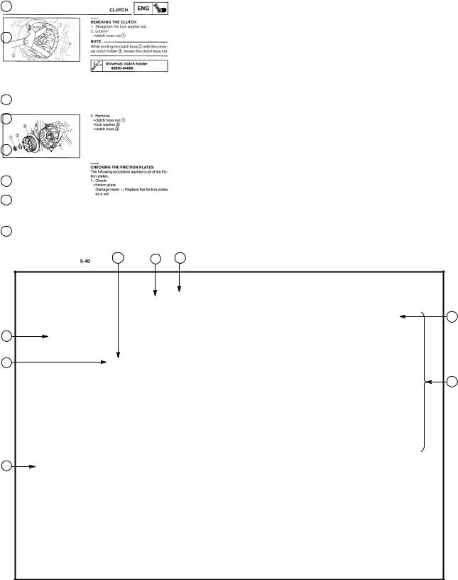
5Numbers are given in the order of the jobs in the exploded diagram. A circled number indicates a disassembly step.
6Symbols indicate parts to be lubricated or replaced (see ªSYMBOLSº).
7A job instruction chart accompanies the exploded diagram, providing the order of jobs, names of parts, notes in jobs, etc.
8Jobs requiring more information (such as special tools and technical data) are described sequentially.
|
6 |
2 |
1 |
|
3 |
||
|
4 |
||
|
5 |
||
|
8 |
||
|
7 |
|
GEN |
SPEC |
|
|
INFO |
||
|
3 |
4 |
|
|
CHK |
CHAS |
|
|
ADJ |
||
|
5 |
6 |
|
|
ENG |
COOL |
|
|
7 |
8 |
|
|
CARB |
ELEC |
|
|
9 |
10 |
|
|
TRBL |
||
|
SHTG |
||
|
11 |
12 |
EAS00008
SYMBOLS
The following symbols are not relevant to every vehicle.
Symbols 1 to 9 indicate the subject of each chapter.
1General information
2Specifications
3Periodic checks and adjustments
4Chassis
5Engine
6Cooling system
7Carburetor(-s)
8Electrical system
9Troubleshooting
Symbols 10 to 17 indicate the following.
10Serviceable with engine mounted
11Filling fluid
12Lubricant
13Special tool
14Tightening torque
15Wear limit, clearance
16Engine speed
17Electrical data
Symbols 18 to 23 in the exploded diagrams indicate the types of lubricants and lubrication points.
18Engine oil
19Gear oil
20Molybdenum disulfide oil
21Wheel bearing grease
22Lithium soap base grease
23Molybdenum disulfide grease
Symbols 24 to 25 in the exploded diagrams indicate the following:
24Apply locking agent (LOCTITER)
25Replace the part

EAS00012
TABLE OF CONTENTS
|
GENERAL INFORMATION |
|||||
|
GEN |
1 |
||||
|
INFO |
|||||
|
SPECIFICATIONS |
|||||
|
SPEC |
2 |
||||
|
PERIODIC CHECKS AND |
|||||
|
CHK |
3 |
||||
|
ADJUSTMENTS |
|||||
|
ADJ |
|||||
|
CHASSIS |
|||||
|
CHAS |
4 |
||||
|
ENGINE |
|||||
|
ENG |
5 |
||||
|
COOLING SYSTEM |
|||||
|
COOL |
6 |
||||
|
CARBURETORS |
|||||
|
CARB |
7 |
||||
|
ELECTRICAL SYSTEM |
|||||
|
ELEC |
8 |
||||
|
TROUBLESHOOTING |
|||||
|
TRBL |
9 |
||||
|
SHTG |
GEN
INFO
CHAPTER 1
GENERAL INFORMATION
MOTORCYCLE IDENTIFICATION . . . . . . . . . . . . . . . . . . . . . . . . . . . . . . . 1-1 VEHICLE IDENTIFICATION NUMBER . . . . . . . . . . . . . . . . . . . . . . . . . 1-1 MODEL CODE . . . . . . . . . . . . . . . . . . . . . . . . . . . . . . . . . . . . . . . . . . . . . 1-1
IMPORTANT INFORMATION . . . . . . . . . . . . . . . . . . . . . . . . . . . . . . . . . . . . 1-2 PREPARATION FOR REMOVAL AND DISASSEMBLY . . . . . . . . . . 1-2 REPLACEMENT PARTS . . . . . . . . . . . . . . . . . . . . . . . . . . . . . . . . . . . . . 1-2 GASKETS, OIL SEALS AND O-RINGS . . . . . . . . . . . . . . . . . . . . . . . . 1-2 LOCK WASHERS/PLATES AND COTTER PINS . . . . . . . . . . . . . . . . 1-2 BEARINGS AND OIL SEALS . . . . . . . . . . . . . . . . . . . . . . . . . . . . . . . . . 1-3 CIRCLIPS . . . . . . . . . . . . . . . . . . . . . . . . . . . . . . . . . . . . . . . . . . . . . . . . . . 1-3
CHECKING THE CONNECTIONS . . . . . . . . . . . . . . . . . . . . . . . . . . . . . . . 1-4
SPECIAL TOOLS . . . . . . . . . . . . . . . . . . . . . . . . . . . . . . . . . . . . . . . . . . . . . . 1-5
![]()
GEN INFO
GEN
MOTORCYCLE IDENTIFICATION INFO
EAS00014
GENERAL INFORMATION
MOTORCYCLE IDENTIFICATION
EAS00017
VEHICLE IDENTIFICATION NUMBER
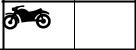
The vehicle identification number 1 is stamped into the right side of the steering head.
EAS00018
MODEL CODE
The model code label 1 is affixed to the frame. This information will be needed to order spare parts.
1-1
GEN
IMPORTANT INFORMATION INFO
EAS00020
IMPORTANT INFORMATION
PREPARATION FOR REMOVAL AND DISASSEMBLY
1.Before removal and disassembly, remove all dirt, mud, dust and foreign material.
2.Use only the proper tools and cleaning equipment.
Refer to the ªSPECIAL TOOLSº section.
3.When disassembling, always keep mated parts together. This includes gears, cylinders, pistons and other parts that have been ºmatedº through normal wear. Mated parts must always be reused or replaced as an assembly.
4.During disassembly, clean all of the parts and place them in trays in the order of disassembly. This will speed up assembly and allow for the correct installation of all parts.
5.Keep all parts away from any source of fire.
EAS00021
REPLACEMENT PARTS
1.Use only genuine Yamaha parts for all replacements. Use oil and grease recommended by Yamaha for all lubrication jobs. Other brands may be similar in function and appearance, but inferior in quality.
EAS00022
GASKETS, OIL SEALS AND O-RINGS
1.When overhauling the engine, replace all gaskets, seals and O-rings. All gasket surfaces, oil seal lips and O-rings must be cleaned.
2.During reassembly, properly oil all mating
|
grease |
parts and bearings and apply grease onto |
|
the oil seal lips with greace. |
EAS00023
LOCK WASHERS/PLATES AND COTTER PINS
1.After removal, replace all lock washers/plates 1 and cotter pins. After the bolt or nut has been tightened to specification, bend the lock tabs along a flat of the bolt or nut.
1-2
IMPORTANT INFORMATION
EAS00024
GEN INFO
BEARINGS AND OIL SEALS
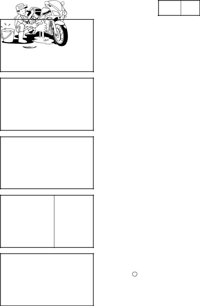
1.Install bearings and oil seals so that the manufacturer’s marks or numbers are visible. When installing oil seals, apply a light coat of lithium soap base grease onto the oil seal lips. Oil bearings liberally when installing, if appropriate.
1 Oil seal
CAUTION:
Do not spin the bearing with compressed air because this will damage the bearing surfaces.
1 Bearing
EAS00025
CIRCLIPS
1.Before reassembly, check all circlips carefully and replace damaged or distorted circlips. Always replace piston pin clips after one use. When installing a circlip 1 , make sure that the sharp-edged corner 2 is positioned opposite the thrust 3 that the circlip receives.
4 Shaft
1-3
GEN
CHECKING THE CONNECTIONS INFO
EAS00026
CHECKING THE CONNECTIONS
Check the leads, couplers, and connectors for stains, rust, moisture, etc.
1.Disconnect:
lead 1
coupler 2
connector 3
2.Check:
lead
coupler
connector
Moisture Dry with an air blower. Rust/stains Connect and disconnect several times.
3.Check:
all connections
Loose connection Connect properly.
NOTE:
If the pin 1 on the terminal is flattened, bend it up.
4.Connect:
lead
coupler
connector
NOTE:
Make sure that all connections are tight.
5.Check:
continuity
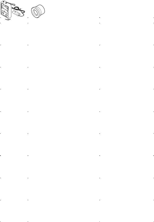
(with a pocket tester)
Pocket tester 90890-03112
NOTE:
If there is no continuity, clean the terminals.
When checking the wire harness, perform steps 1 to 3.
As a quick remedy, use a contact revitalizer available at most part stores.
1-4
GEN
SPECIAL TOOLS INFO
EAS00027
SPECIAL TOOLS
The following special tools are necessary for complete and accurate tune-up and assembly. Use only the appropriate special tools as this will help prevent damage caused by the use of inappropriate tools or improvised techniques. Special tools, part numbers or both may differ depending on the country. When placing an order, refer to the list provided below to avoid any mistakes.
|
Tool No. |
Tool name/Function |
Illustration |
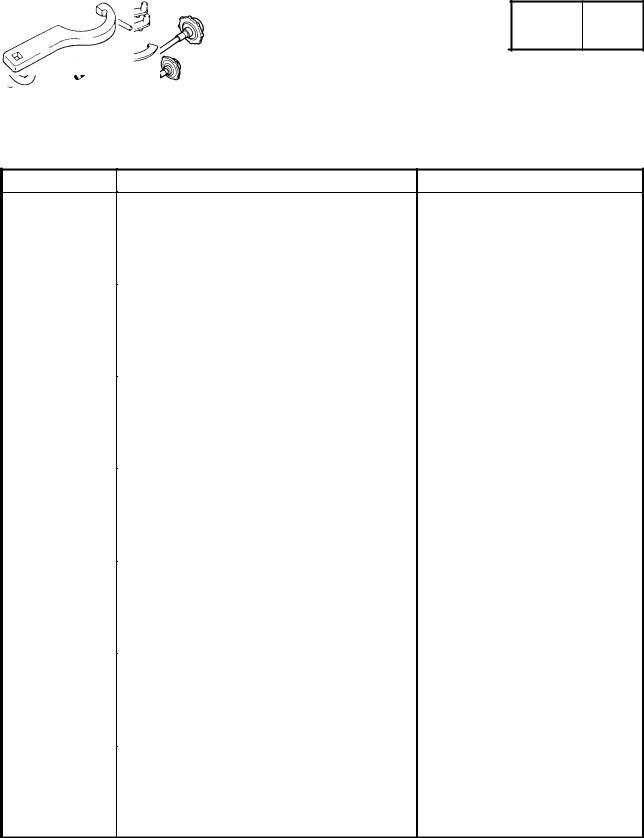
Rotor puller
|
90890-01080 |
|
|
This tool is used to remove the generator |
|
|
rotor. |
|
|
Rotor holding tool |
|
|
90890-01235 |
This tool is used to hold the generator rotor |
|
when removing or installing the generator |
|
|
rotor bolt or pickup coil rotor bolt. |
|
|
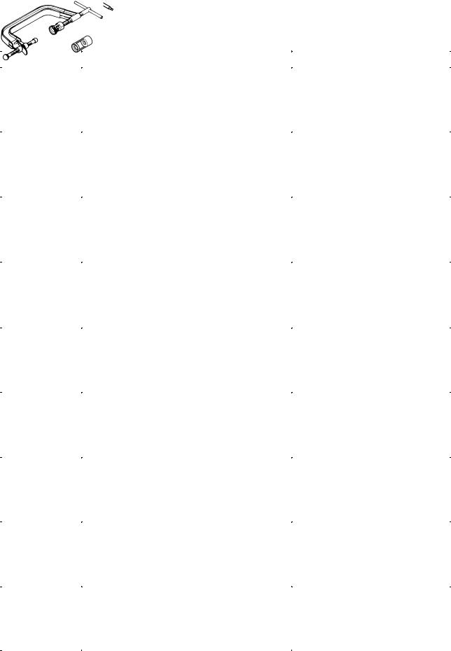
Piston pin puller set |
|
|
90890-01304 |
|
|
This tool is used to remove the piston pins. |
|
|
Fuel level gauge |
|
|
90890-01312 |
|
|
This tool is used to measure the fuel level in |
|
|
the float chamber. |
|
|
Radiator cap |
Radiator cap tester |
|
tester |
Adapter |
|
90890-01325 |
|
|
Adapter |
These tools are used to check the cooling |
|
90890-01352 |
system. |
|
Steering nut wrench |
|
|
90890-01403 |
|
|
This tool is used to loosen or tighten the |
|
|
steering stem ring nuts. |
|
|
Damper rod holder |
|
|
90890-01447 |
This tool is used to hold the damper rod as- |
|
sembly when loosening or tightening the |
|
|
damper rod assembly bolt. |
1-5
|
SPECIAL TOOLS |
GEN |
|||||
|
INFO |
||||||
|
Tool No. |
Tool name/Function |
Illustration |
||||
|
Oil filter wrench |
||||||
|
90890-01426 |
||||||
|
This tool is needed to loosen or tighten the |
||||||
|
oil filter cartridge. |
||||||
|
Rod holder |
||||||
|
90890-01434 |
||||||
|
This tool is used to support the damper ad- |
||||||
|
justing rod. |
||||||
|
Rod puller |
Rod puller |
|||||
|
90890-01437 |
Rod puller attachment |
|||||
|
Rod puller |
||||||
|
attachment |
These tools are used to pull up the front |
|||||
|
90890-01436 |
fork damper rod. |
|||||
|
Fork seal driver |
Fork seal driver weight |
|||||
|
weight |
Fork seal driver attachment (ù43) |
|||||
|
90890-01367 |
||||||
|
Fork seal driver |
This tool is used to install the front fork’s oil |
|||||
|
attachment (ù43) |
||||||
|
seal and dust seal. |
||||||
|
90890-01374 |
||||||
|
Micrometer (50 75 mm) |
||||||
|
90890-03008 |
||||||
|
This tool is used to measure the piston skirt |
||||||
|
diameter. |
||||||
|
Vacuum gauge |
||||||
|
Vacuum gauge |
||||||
|
90890-03094 |
This guide is used to synchronize the car- |
|||||
|
buretors. |
||||||
|
Compression |
Compression gauge |
|||||
|
gauge |
Compression gauge adapter |
|||||
|
90890-03081 |
||||||
|
Compression |
These tools are used to measure engine |
|||||
|
gauge adapter |
||||||
|
compression. |
||||||
|
90890-04136 |
||||||
|
Pocket tester |
||||||
|
90890-03112 |
||||||
|
This tool is used to check the electrical sys- |
||||||
|
tem. |
||||||
|
Engine tachometer |
||||||
|
90890-03113 |
||||||
|
This tool is used to check engine speed. |
||||||
1-6
|
SPECIAL TOOLS |
GEN |
|||||
|
INFO |
||||||
|
Tool No. |
Tool name/Function |
Illustration |
||||
|
Timing light |
||||||
|
90890-03141 |
||||||
|
This tool is used to check the ignition tim- |
||||||
|
ing. |
||||||
|
Carburetor angle driver 2 |
||||||
|
90890-03173 |
||||||
|
This tool is used to turn the pilot screw |
||||||
|
when adjusting the engine idling speed. |
||||||
|
Valve spring com- |
Valve spring compressor |
|||||
|
pressor |
Valve spring compressor attachment |
|||||
|
90890-04019 |
||||||
|
Attachmenht |
These tools are used to remove or install |
|||||
|
90890-04108 |
||||||
|
the valve assemblies. |
||||||
|
90890-04114 |
||||||
|
Middle driven shaft |
Middle driven shaft bearing driver |
|||||
|
bearing driver |
Mechanical seal installer |
|||||
|
90890-04058 |
||||||
|
Mechanical seal |
These tools are used to install the water |
|||||
|
installer |
||||||
|
pump seal. |
||||||
|
90890-04078 |
||||||
|
Universal clutch holder |
||||||
|
90890-04086 |
This tool is used to hold the clutch boss |
|||||
|
when removing or installing the clutch boss |
||||||
|
nut. |
||||||
|
Valve guide remover (ù4) |
||||||
|
90890-04111 |
Valve guide remover (ù4.5) |
|||||
|
90890-04116 |
This tool is used to remove or install the |
|||||
|
valve guides. |
||||||
|
Valve guide installer (ù4) |
||||||
|
90890-04112 |
Valve guide installer (ù4.5) |
|||||
|
90890-04117 |
||||||
|
This tool is used to install the valve guides. |
||||||
|
Valve guide reamer (ù4) |
||||||
|
90890-04113 |
Valve guide reamer (ù4.5) |
|||||
|
90890-04118 |
This tool is used to rebore the new valve |
|||||
|
guides. |
||||||
|
Ignition checker |
||||||
|
90890-06754 |
||||||
|
This tool is used to check the ignition sys- |
||||||
|
tem components. |
||||||
1-7
|
SPECIAL TOOLS |
GEN |
|||||
|
INFO |
||||||
|
Tool No. |
Tool name/Function |
Illustration |
||||
|
Yamaha bond No. 1215 |
||||||
|
90890-85505 |
||||||
|
This bond is used to seal two mating sur- |
||||||
|
faces (e.g., crankcase mating surfaces). |
||||||
1-8
![]()
SPEC 


CHAPTER 2.
SPECIFICATIONS
GENERAL SPECIFICATIONS . . . . . . . . . . . . . . . . . . . . . . . . . . . . . . . . . . . 2-1
ENGINE SPECIFICATIONS . . . . . . . . . . . . . . . . . . . . . . . . . . . . . . . . . . . . . 2-2
CHASSIS SPECIFICATIONS . . . . . . . . . . . . . . . . . . . . . . . . . . . . . . . . . . . . 2-11
ELECTRICAL SPECIFICATIONS . . . . . . . . . . . . . . . . . . . . . . . . . . . . . . . . 2-15
TIGHTENING TORQUES . . . . . . . . . . . . . . . . . . . . . . . . . . . . . . . . . . . . . . . 2-18 GENERAL TIGHTENING TORQUES . . . . . . . . . . . . . . . . . . . . . . . . . . 2-18 ENGINE TIGHTENING TORQUES . . . . . . . . . . . . . . . . . . . . . . . . . . . . 2-19 CHASSIS TIGHTENING TORQUES . . . . . . . . . . . . . . . . . . . . . . . . . . . 2-22
LUBRICATION POINTS AND LUBRICANT TYPES . . . . . . . . . . . . . . . . 2-23 ENGINE . . . . . . . . . . . . . . . . . . . . . . . . . . . . . . . . . . . . . . . . . . . . . . . . . . . 2-23 CHASSIS . . . . . . . . . . . . . . . . . . . . . . . . . . . . . . . . . . . . . . . . . . . . . . . . . . 2-24
COOLING SYSTEM DIAGRAMS . . . . . . . . . . . . . . . . . . . . . . . . . . . . . . . . 2-25
ENGINE OIL LUBRICATION CHART . . . . . . . . . . . . . . . . . . . . . . . . . . . . . 2-29
LUBRICATION DIAGRAMS . . . . . . . . . . . . . . . . . . . . . . . . . . . . . . . . . . . . . 2-30
CABLE ROUTING . . . . . . . . . . . . . . . . . . . . . . . . . . . . . . . . . . . . . . . . . . . . . 2-35

|
GENERAL SPECIFICATIONS |
SPEC |
|||||
|
SPECIFICATIONS |
||||||
|
GENERAL SPECIFICATIONS |
||||||
|
Item |
Standard |
Limit |
||||
|
Model code |
5VL1 (A) (B) (D) (DK) (E) (GB) (GR) (I) |
|||||
|
(N) (NL) (S) (SF) (CH) (P) |
||||||
|
5LV2 (F) |
||||||
|
5LV3 (D) |
||||||
|
5LV4 (AUS) |
||||||
|
Dimensions |
||||||
|
Overall length |
2,125 mm |
|||||
|
Overall width |
765 mm |
|||||
|
Overall height |
1,190 mm |
|||||
|
Seat height |
820 mm |
|||||
|
Wheelbase |
1,450 mm |
|||||
|
Minimum ground clearance |
140 mm |
|||||
|
Minimum turning radius |
2,900 mm |
|||||
|
Weight |
||||||
|
Wet (with oil and a full fuel tank) |
231 kg |
|||||
|
Dry (without oil and fuel) |
208 kg |
|||||
|
Maximum load (total of cargo, rider, |
189 kg |
|||||
|
passenger, and accessories) |
||||||
2-1
|
ENGINE SPECIFICATIONS |
SPEC |
||||
|
ENGINE SPECIFICATIONS |
|||||
|
Item |
Standard |
Limit |
|||
|
Engine |
|||||
|
Engine type |
Liquid-cooled, 4-stroke, DOHC |
||||
|
Displacement |
998 cm3 |
||||
|
Cylinder arrangement |
Forward-inclined parallel 4-cylinder |
||||
|
Bore stroke |
74 58 mm |
||||
|
Compression ratio |
11.4 : 1 |
||||
|
Engine idling speed |
1,050 1,150 r/min |
||||
|
Vacuum pressure at engine idling |
30 kPa (225 mm Hg) |
||||
|
speed |
1,450 kPa (14.5 kg/cm2) at 400 r/min |
||||
|
Standard compression pressure |
|||||
|
(at sea level) |
|||||
|
Fuel |
|||||
|
Recommended fuel |
Regular unleaded gasoline |
||||
|
Fuel tank capacity |
|||||
|
Total (including reserve) |
21 L |
||||
|
Reserve only |
4.0 L |
||||
|
Engine oil |
|||||
|
Lubrication system |
Wet sump |
||||
|
Recommended oil |
|||||
|
SAE20W40SE or SAE10W30SE |
|
Quantity |
||
|
Total amount |
3.7 L |
|
|
Without oil filter cartridge |
2.8 L |
|
|
replacement |
||
|
With oil filter cartridge replacement |
3.0 L |
|
|
Oil pressure (hot) |
45 kPa at 1,100 r/min |
|
|
(0.45 kg/cm2 at 1,100 r/min) |
||
|
Relief valve opening pressure |
490 570 kPa (4.9 5.7 kg/cm2) |
2-2
|
ENGINE SPECIFICATIONS |
SPEC |
|||||
|
Item |
Standard |
Limit |
||||
|
Oil filter |
||||||
|
Oil filter type |
Cartridge (paper) |
|||||
|
Bypass valve opening pressure |
180 220 kPa (1.8 2.2 kg/cm2) |
|||||
|
Oil pump |
||||||
|
Oil pump type |
Trochoid |
|||||
|
Inner-rotor-to-outer-rotor-tip |
0.09 0.15 mm |
|||||
|
clearance |
||||||
|
Outer-rotor-to-oil-pump-housing |
0.03 0.08 mm |
|||||
|
clearance |
||||||
|
Cooling system |
||||||
|
Radiator capacity |
2.4 L |
|||||
|
Radiator cap opening pressure |
95 125 kPa (0.95 1.25 kg/cm2) |
|||||
|
Radiator core |
||||||
|
Width |
340 mm |
|||||
|
Height |
238 mm |
|||||
|
Depth |
24 mm |
|||||
|
Coolant reservoir |
||||||
|
Capacity |
0.3 L |
|||||
|
Water pump |
||||||
|
Water pump type |
Single-suction centrifugal pump |
|||||
|
Reduction ratio |
68/43 28/28 (1.581) |
|||||
|
Max. impeller shaft tilt |
0.15 mm |
|||||
|
Starting system type |
Electric starter |
|||||
|
Spark plugs |
||||||
|
Model (manufacturer) quantity |
CR9E/U27ESR-N (NGK/DENSO) 4 |
|||||
|
Spark plug gap |
0.7 0.8 mm |
|||||
|
Cylinder head |
||||||
|
Max. warpage |
0.1 mm |
|||||
2-3
|
ENGINE SPECIFICATIONS |
SPEC |
|||
|
Item |
Standard |
Limit |
||
|
Camshafts |
||||
|
Drive system |
Chain drive (right) |
|||
|
Camshaft cap inside diameter |
24.500 X 24.521 mm |
|||
|
Camshaft journal diameter |
24.459 X 24.472 mm |
|||
|
Camshaft-journal-to-camshaft- |
0.028 X 0.062 mm |
|||
|
cap clearance |
||||
|
Intake camshaft lobe dimensions |
|
Measurement A |
32.5 X 32.6 mm |
32.4 mm |
|
Measurement B |
24.95 X 25.05 mm |
24.85 mm |
|
Measurement C |
7.45 X 7.65 mm |
Exhaust camshaft lobe dimensions
|
Measurement A |
32.95 X 33.05 mm |
32.85 mm |
|
Measurement B |
24.95 X 25.05 mm |
24.85 mm |
|
Measurement C |
7.75 X 7.95 mm |
|
|
Max. camshaft runout |
0.03 mm |
2-4
|
ENGINE SPECIFICATIONS |
SPEC |
||||
|
Item |
Standard |
Limit |
|||
|
Timing chain |
|||||
|
Model/number of links |
RH2015/130 |
||||
|
Tensioning system |
Automatic |
||||
|
Valves, valve seats, valve guides |
|||||
|
Valve clearance (cold) |
|||||
|
Intake |
0.11 X 0.20 mm |
||||
|
Exhaust |
0.21 X 0.25 mm |
||||
|
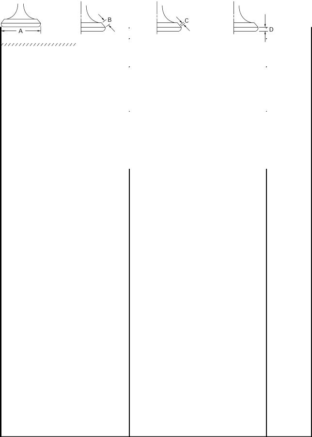
Valve dimensions |
|||||
|
Head Diameter |
Face Width |
Seat Width |
Margin Thickness |
|
Valve head diameter A |
|||
|
Intake |
22.9 X 23.1 mm |
||
|
Exhaust |
24.4 X 24.6 mm |
||
|
Valve face width B |
|||
|
Intake |
1.76 X 2.90 mm |
||
|
Exhaust |
1.76 X 2.90 mm |
||
|
Valve seat width C |
|||
|
Intake |
0.9 X 1.1 mm |
||
|
Exhaust |
0.9 X 1.1 mm |
||
|
Valve margin thickness D |
|||
|
Intake |
0.5 X 0.9 mm |
||
|
Exhaust |
0.5 X 0.9 mm |
||
|
Valve stem diameter |
|||
|
Intake |
3.975 X 3.990 mm |
3.945 mm |
|
|
Exhaust |
4.465 X 4.480 mm |
4.43 mm |
|
|
Valve guide inside diameter |
|||
|
Intake |
4.000 X 4.012 mm |
4.05 mm |
|
|
Exhaust |
4.500 X 4.512 mm |
4.55 mm |
|
|
Valve-stem-to-valve-guide clearance |
|||
|
Intake |
0.010 X 0.037 mm |
0.08 mm |
|
|
Exhaust |
0.020 X 0.047 mm |
0.10 mm |
|
|
Valve stem runout |
0.01 mm |
|
Valve seat width |
||
|
Intake |
0.9 X 1.1 mm |
|
|
Exhaust |
0.9 X 1.1 mm |
2-5
|
ENGINE SPECIFICATIONS |
SPEC |
|||
|
Item |
Standard |
Limit |
||
|
Valve springs |
||||
|
Free length |
||||
|
Intake |
38.9 mm |
|||
|
Exhaust |
40.67 mm |
|||
|
Installed length (valve closed) |
||||
|
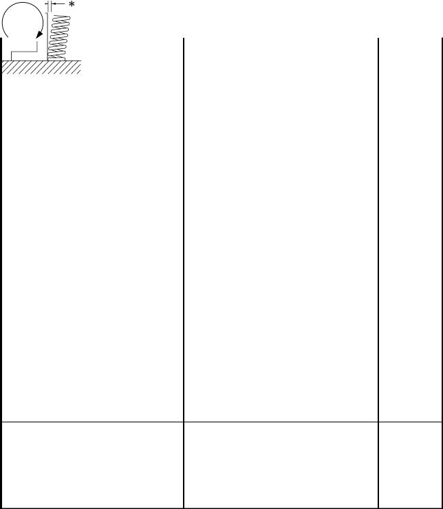
Intake |
34.5 mm |
|||
|
Exhaust |
35 mm |
|||
|
Compressed spring force |
||||
|
(installed) |
||||
|
Intake |
82 96 N (8.36 9.79 kg) |
|||
|
Exhaust |
110 126 N (11.22 12.85 kg) |
|||
|
Spring tilt |
|
Intake |
2.5_/ |
|
|
1.7 mm |
||
|
Exhaust |
2.5_/ |
|
|
1.8 mm |
||
|
Winding direction (top view) |
||
|
Intake |
Clockwise |
|
|
Exhaust |
Clockwise |
|
Cylinders |
||
|
Cylinder arrangement |
Forward-inclined, parallel 4-cylinder |
|
|
Bore stroke |
74 58 mm |
|
|
Compression ratio |
11.4 : 1 |
|
|
Bore |
74.00 74.01 mm |
|
|
Max. taper |
0.05 mm |
|
|
Max. out-of-round |
0.05 mm |
2-6
|
ENGINE SPECIFICATIONS |
SPEC |
|||
|
Item |
Standard |
Limit |
||
|
Piston |
||||
|
Piston-to-cylinder clearance |
0.030 0.055 mm |
0.12 mm |
||
|
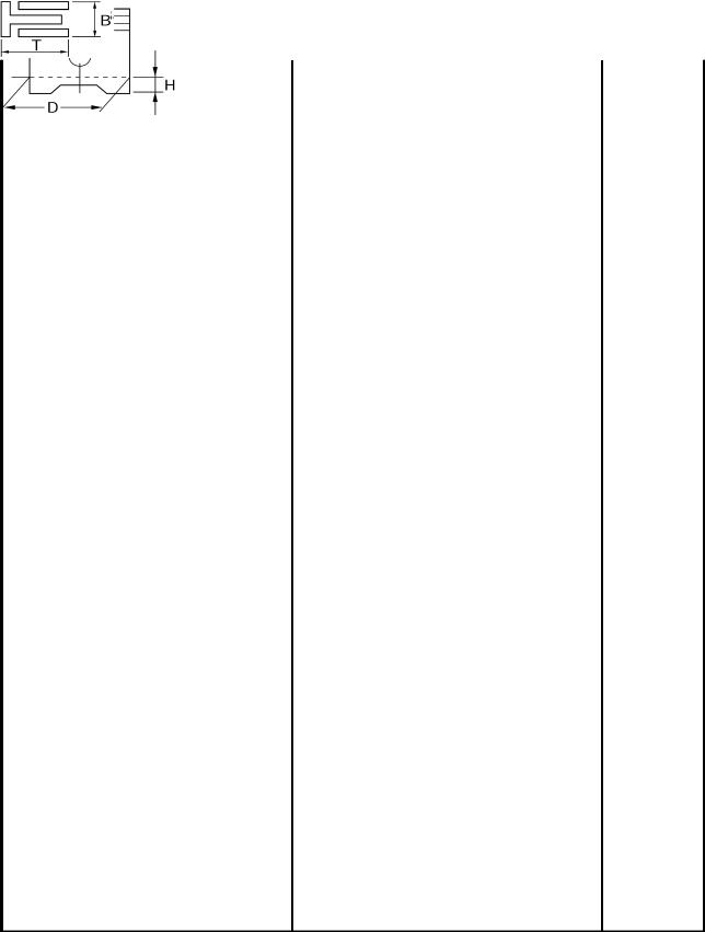
Diameter D |
73.955 73.970 mm |
|
Height H |
5 mm |
|
|
Piston pin bore (in the piston) |
||
|
Diameter |
17.002 17.013 mm |
17.043 |
|
Offset |
||
|
Offset direction |
Intake side |
|
|
Piston pins |
||
|
Outside diameter |
16.991 17.000 mm |
16.971 |
|
Piston-pin-to-piston-pin-bore |
0.002 0.022 mm |
0.072 mm |
|
clearance |
||
|
Piston rings |
||
|
Top ring |
|
Ring type |
Barrel |
|
|
Dimensions (B T) |
0.90 2.75 mm |
|
|
End gap (installed) |
0.32 0.44 mm |
|
|
Ring side clearance |
0.030 0.065 mm |
2nd ring
|
Ring type |
Taper |
|
|
Dimensions (B T) |
0.8 2.8 |
|
|
End gap (installed) |
0.43 0.58 mm |
|
|
Ring side clearance |
0.020 0.055 mm |
Oil ring
|
Dimensions (B T) |
1.5 2.6 mm |
|
|
End gap (installed) |
0.10 0.35 |
2-7
|
ENGINE SPECIFICATIONS |
SPEC |
|||
|
Item |
Standard |
Limit |
||
|
Connecting rods |
||||
|
Crankshaft-pin-to-big-end-bearing |
0.031 X 0.055 mm |
|||
|
clearance |
||||
|
Bearing color code |
±1 = Violet 0 = White 1 = Blue 2 = Black |
|||
|
Crankshaft |
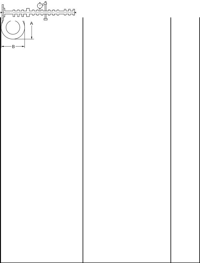
|
Width A |
52.40 X 57.25 mm |
||
|
Width B |
300.75 X 302.65 mm |
||
|
Max. runout C |
0.03 mm |
||
|
Big end side clearance D |
0.160 X 0.262 mm |
||
|
Crankshaft-journal-to-crankshaft- |
0.029 X 0.053 mm |
||
|
journal-bearing clearance |
|||
|
Bearing color code |
±1 = Pink/violet 0 = Pink/white |
||
|
1 |
= Pink/blue 2 = Pink/black |
||
|
3 |
= Pink/brown |
||
|
Clutch |
|||
|
Clutch type |
Wet, multiple disc |
||
|
Clutch release method |
Cam (pull rod type) |
||
|
Clutch release method operation |
Cable operation |
||
|
Operation |
Left-hand operation |
||
|
Clutch cable free play (at the end |
10 X 15 mm |
||
|
of the clutch lever) |
|||
|
Friction plates |
|||
|
Thickness |
2.92 X 3.08 mm |
2.82 mm |
|
|
Plate quantity |
8 |
||
|
Thickness |
3.42 X 3.58 mm |
3.32 mm |
|
|
Plate quantity |
1 |
||
|
Clutch plates |
|||
|
Thickness |
1.9 X 2.1 mm |
||
|
Plate quantity |
8 |
||
|
Max. warpage |
0.1 mm |
||
|
Clutch springs |
|||
|
Free length |
50 mm |
||
|
Spring quantity |
6 |
2-8
![]()
|
ENGINE SPECIFICATIONS |
SPEC |
||||
|
Item |
Standard |
Limit |
|||
|
Transmission |
|||||
|
Transmission type |
Constant mesh, 6-speed |
||||
|
Primary reduction system |
Spur gear |
||||
|
Primary reduction ratio |
68/43 (1.581) |
||||
|
Secondary reduction system |
Chain drive |
||||
|
Secondary reduction ratio |
44/16 (2.750) |
||||
|
Operation |
Left-foot operation |
||||
|
Gear ratios |
|||||
|
1st gear |
35/14 (2.500) |
||||
|
2nd gear |
35/19 (1.842) |
||||
|
3rd gear |
30/20 (1.500) |
||||
|
4nd gear |
28/21 (1.333) |
||||
|
5th gear |
30/25 (1.200) |
||||
|
6th gear |
29/26 (1.115) |
||||
|
Max. main axle runout |
0.08 mm |
||||
|
Max. drive axle runout |
0.08 mm |
||||
|
Shifting mechanism |
|||||
|
Shift mechanism type |
Guide bar |
||||
|
Max. shift fork guide bar bending |
0.1 mm |
||||
|
Installed shift rod length |
260 mm |
||||
|
Air filter type |
Dry element |
||||
|
Fuel pump |
|||||
|
Pump type |
Electrical |
||||
|
Model (manufacturer) |
4SV (MITSUBISHI) |
||||
|
Output pressure |
20 kPa (0.2 kg/cm2) |
2-9

|
ENGINE SPECIFICATIONS |
SPEC |
||||
|
Item |
Standard |
Limit |
|||
|
Carburetors |
|||||
|
Model (manufacturer) quantity |
BSR37 (MIKUNI) 4 |
||||
|
Throttle cable free play (at the |
3 5 mm |
||||
|
flange of the throttle grip) |
|||||
|
ID mark |
5LV1 00 |
||||
|
Main jet |
Carburetors 1 and 4: #132.5 |
||||
|
Carburetors 2 and 3: #130 |
|||||
|
Main air jet |
#80 |
||||
|
Jet needle |
Carburetor 1 and 4: 5D129-3/5 |
||||
|
Carburetor 2 and 3: 5D130-3/5 |
|||||
|
Needle jet |
P-OM |
||||
|
Pilot air jet |
#85 |
||||
|
Pilot outlet |
1.0 |
||||
|
Pilot jet |
#15 |
||||
|
Bypass 1 |
0.9 |
||||
|
Bypass 2 |
0.9 |
||||
|
Bypass 3 |
0.9 |
||||
|
Pilot screw turns out |
2.0 |
||||
|
Valve seat size |
1.5 |
||||
|
Starter jet 1 |
#42.5 |
||||
|
Starter jet 2 |
0.8 |
||||
|
Throttle valve size |
#115 |
||||
|
Fuel level (above the line on the |
3.0 4.0 mm |
||||
|
float chamber) |
|||||
|
Max. EXUP cable free play (at the |
1.5 mm |
||||
|
EXUP valve pulley) |
2-10

|
CHASSIS SPECIFICATIONS |
SPEC |
|||||
|
CHASSIS SPECIFICATIONS |
||||||
|
Item |
Standard |
Limit |
||||
|
Frame |
||||||
|
Frame type |
Double cradle |
|||||
|
Caster angle |
26_ |
|||||
|
Trail |
104 mm |
|||||
|
Front wheel |
||||||
|
Wheel type |
Cast wheel |
|||||
|
Rim |
||||||
|
Size |
17 MT3.50 |
|||||
|
Material |
Aluminum |
|||||
|
Wheel travel |
140 mm |
|||||
|
Wheel runout |
||||||
|
Max. radial wheel runout |
1 mm |
|||||
|
Max. lateral wheel runout |
0.5 mm |
|||||
|
Rear wheel |
||||||
|
Wheel type |
Cast wheel |
|||||
|
Rim |
||||||
|
Size |
17 MT5.50 |
|||||
|
Material |
Aluminum |
|||||
|
Wheel travel |
135 mm |
|||||
|
Wheel runout |
||||||
|
Max. radial wheel runout |
1 mm |
|||||
|
Max. lateral wheel runout |
0.5 mm |
|||||
|
Front tire |
||||||
|
Tire type |
Tubeless |
|||||
|
Size |
120/70 ZR17 (58W) |
|||||
|
Model (manufacturer) |
MEZ4Y FRONT (METZELER) |
|||||
|
BT020F U (BRIDGESTONE) |
||||||
|
Tire pressure (cold) |
250 kPa (2.5 kgf/cm2, 2.5 bar) |
|||||
|
0 90 kg |
||||||
|
90 201 kg |
250 kPa (2.5 kgf/cm2, 2.5 bar) |
|||||
|
High-speed riding |
250 kPa (2.5 kgf/cm2, 2.5 bar) |
|||||
|
Min. tire tread depth |
1.6 mm |
2-11

|
CHASSIS SPECIFICATIONS |
SPEC |
|||
|
Item |
Standard |
Limit |
||
|
Rear tire |
||||
|
Tire type |
Tubeless |
|||
|
Size |
180/55 ZR17 (73W) |
|||
|
Model (manufacturer) |
MEZ4Y (METZELER) |
|||
|
BT020R U (BRIDGESTONE) |
||||
|
Tire pressure (cold) |
270 kPa (2.7 kgf/cm2, 2.7 bar) |
|||
|
0 90 kg |
||||
|
90 201 kg |
290 kPa (2.9 kgf/cm2, 2.9 bar) |
|||
|
High-speed riding |
290 kPa (2.9 kgf/cm2, 2.9 bar) |
|||
|
Min. tire tread depth |
1.6 mm |
|||
|
Front brakes |
||||
|
Brake type |
Dual-disc brake |
|||
|
Operation |
Right-hand-operation |
|||
|
Recommended fluid |
DOT 4 |
|||
|
Brake discs |
||||
|
Diameter thickness |
298 5 mm |
|||
|
Min. thickness |
4.5 mm |
|||
|
Max. deflection |
0.1 mm |
|||
|
Brake pad lining thickness |
5.5 mm |
0.5 mm |
|
Master cylinder inside diameter |
14 mm |
|
|
Caliper cylinder inside diameter |
30.2 mm and 27 mm |
|
|
Rear brake |
||
|
Brake type |
Single-disc brake |
|
|
Operation |
Right-foot operation |
|
|
Brake pedal position (from the top |
35 40 mm |
|
|
of the brake pedal to the top of the |
||
|
rider footrest) |
||
|
Recommended fluid |
DOT 4 |
|
|
Brake discs |
||
|
Diameter thickness |
267 5 mm |
|
|
Min. thickness |
4.5 mm |
|
|
Max. deflection |
0.1 mm |
|
|
Brake pad lining thickness |
5.5 mm |
0.5 mm |
|
Master cylinder inside diameter |
12.7 mm |
|
|
Caliper cylinder inside diameter |
42.9 mm |
2-12

|
CHASSIS SPECIFICATIONS |
SPEC |
|||||
|
Item |
Standard |
Limit |
||||
|
Front suspension |
||||||
|
Suspension type |
Telescopic fork |
|||||
|
Front fork type |
Coil spring/oil damper |
|||||
|
Front fork travel |
140 mm |
|||||
|
Spring |
||||||
|
Free length |
344.0 mm |
|||||
|
Spacer length |
78.5 mm |
|||||
|
Installed length |
320.0 mm |
|||||
|
Spring rate (K1) |
8.1 N/mm (0.83 kg/mm) |
|||||
|
Spring rate (K2) |
11.8 N/mm (1.2 kg/mm) |
|||||
|
Spring stroke (K1) |
0 55 mm |
|||||
|
Spring stroke (K2) |
55 140 mm |
|||||
|
Optional spring available |
No |
|||||
|
Fork oil |
||||||
|
Recommended oil |
Suspension oil ª01º or equivalent |
|||||
|
Quantity (each front fork leg) |
440 cm3 |
|||||
|
Level (from the top of the inner |
140 mm |
|||||
|
tube, with the inner tube fully |
||||||
|
compressed, and without the |
||||||
|
fork spring) |
||||||
|
Spring preload adjusting positions |
||||||
|
Minimum |
5 (fully turned out position) |
|||||
|
Standard |
2 |
|||||
|
Maximum |
1 |
|||||
|
Rebound damping adjusting |
||||||
|
positions |
||||||
|
Minimum* |
17 |
|||||
|
Standard* |
7 |
|||||
|
Maximum* |
1 |
|||||
|
Compression damping adjusting |
||||||
|
positions |
||||||
|
Minimum* |
21 |
|||||
|
Standard* |
6 |
|||||
|
Maximum* |
1 |
|||||
|
*from the fully turned-in position |
2-13

|
CHASSIS SPECIFICATIONS |
SPEC |
|||||
|
Item |
Standard |
Limit |
||||
|
Steering |
||||||
|
Steering bearing type |
Angular ball bearings |
|||||
|
Rear suspension |
||||||
|
Suspension type |
Swingarm (link suspension) |
|||||
|
Rear shock absorber assembly |
Coil spring/gas-oil damper |
|||||
|
type |
||||||
|
Rear shock absorber assembly |
65 mm |
|||||
|
travel |
||||||
|
Spring |
||||||
|
Free length |
182.5 mm |
|||||
|
Installed length |
163 mm |
|||||
|
Spring rate (K1) |
73.6 N/mm (7.5 kgf/mm) |
|||||
|
Spring stroke (K1) |
0 X 65 mm |
|||||
|
Optional spring available |
No |
|||||
|
Standard spring preload gas/air |
1,200 kPa (12 kgf/cm2) |
|||||
|
pressure |
||||||
|
Spring preload adjusting positions |
||||||
|
Minimum |
1 |
|||||
|
Standard |
6 |
|||||
|
Maximum |
11 |
|||||
|
Rebound damping adjusting |
||||||
|
positions |
||||||
|
Minimum* |
20 |
|||||
|
Standard* |
10 |
|||||
|
Maximum* |
3 |
|||||
|
Compression damping adjusting |
||||||
|
positions |
||||||
|
Minimum* |
1 |
|||||
|
Standard* |
7 |
|||||
|
Maximum* |
12 |
|||||
|
*from the fully turned-in position |
||||||
|
Swingarm |
||||||
|
Free play (at the end of the |
||||||
|
swingarm) |
||||||
|
Radial |
1 mm |
|||||
|
Axial |
1 mm |
|||||
|
Drive chain |
||||||
|
Model (manufacturer) |
50ZVM (DAIDO) |
|||||
|
Link quantity |
116 |
|||||
|
Drive chain slack |
40 X 50 mm |
|||||
|
Maximum ten-link section |
150.1 mm |
152.5 mm |
||||
2-14

|
ELECTRICAL SPECIFICATIONS |
SPEC |
|||||
|
ELECTRICAL SPECIFICATIONS |
||||||
|
Item |
Standard |
Limit |
||||
|
System voltage |
12 V |
|||||
|
Ignition system |
||||||
|
Ignition system type |
Transistorized coil ignition |
|||||
|
Ignition timing |
5_ BTDC at 1,100 r/min |
|||||
|
Advanced timing |
55_ BTDC at 5,000 r/min |
|||||
|
Advancer type |
Throttle position sensor and electrical |
|||||
|
Pickup coil resistance/color |
248 372 Ω/Gy-B |
|||||
|
Transistorized coil ignition unit |
TNDF66 (DENSO) |
|||||
|
model (manufacturer) |
||||||
|
Ignition coils |
||||||
|
Model (manufacturer) |
J0313 (DENSO) |
|||||
|
Minimum ignition spark gap |
6 mm |
|||||
|
Primary coil resistance |
1.87 2.53 Ω |
|||||
|
Secondary coil resistance |
12 18 kΩ |
|||||
|
Spark plug caps |
||||||
|
Material |
Rubber |
|||||
|
Resistance |
10 kΩ |
|||||
|
Throttle position sensor standard |
4 6 kΩ |
|||||
|
resistance |
||||||
|
Charging system |
||||||
|
System type |
AC magneto |
|||||
|
Model (manufacturer) |
F4T361 (MITSUBISHI) |
|||||
|
Normal output |
14 V/365 W at 5,000 r/min |
|||||
|
Stator coil resistance/color |
0.27 0.33 Ω at 20_C/W-W |
|||||
|
Rectifier/regulator |
||||||
|
Regulator type |
Semiconductor short circuit |
|||||
|
Model (manufacture) |
SH650C-11 (SHINDENGEN) |
|||||
|
No-load regulated voltage |
14.1 14.9 V |
|||||
|
Rectifier capacity |
18 A |
|||||
|
Withstand voltage |
200 V |
|||||
|
Battery |
||||||
|
Battery type |
GT14B-4 |
|||||
|
Battery voltage/capacity |
12 V/12AH |
|||||
|
Headlight type |
Halogen bulb |
|||||
|
Bulbs (voltage/wattage quantity) |
||||||
|
Headlight |
12 V 60 W/55 W 2 |
|||||
|
Auxiliary light |
12 V 5 W 2 |
|||||
|
Tail/brake light |
12 V 5 W/21 W 2 |
|||||
|
Turn signal light |
12 V 21 W 4 |
|||||
|
Meter light |
12 V 2 W 3 |
|||||
2-15

|
ELECTRICAL SPECIFICATIONS |
SPEC |
||||
|
Item |
Standard |
Limit |
|||
|
Indicator light |
|||||
|
(voltage/wattage quantity) |
|||||
|
Neutral indicator light |
14 V 1.4 W 1 |
||||
|
High beam indicator light |
14 V 1.4 W 1 |
||||
|
Oil level indicator light |
14 V 1.4 W 1 |
||||
|
Turn signal indicator light |
14 V 1.4 W 2 |
||||
|
Fuel indicator light |
12 V 2 W 1 |
||||
|
Water temperature indicator light |
LED |
||||
|
Electric starting system |
|||||
|
System type |
Constant mesh |
||||
|
Starter motor |
|||||
|
Model (manufacturer) |
SM-13 (MITSUBA) |
||||
|
Power output |
0.8 kW |
||||
|
Brushes |
|||||
|
Overall length |
12.5 mm |
4 mm |
|||
|
Spring force |
7.65 10.01 N (780 1,021 gf) |
||||
|
Commutator resistance |
0.025 0.035 Ω |
||||
|
Commutator diameter |
28 mm |
27 mm |
|||
|
Mica undercut |
0.7 mm |
||||
|
Starter relay |
|||||
|
Model (manufacturer) |
MS5F-631 (JIDECO) |
||||
|
Amperage |
180 A |
||||
|
Coil resistance |
4.18 4.62 Ω |
||||
|
Horn |
|||||
|
Horn type |
Plain |
||||
|
Model (manufacturer) quantity |
YF-12 (NIKKO) 1 |
||||
|
Max. amperage |
3 A |
||||
|
Turn signal relay |
|||||
|
Relay type |
Full-transistor |
||||
|
Model (manufacturer) |
FE246BH (DENSO) |
||||
|
Self-cancelling device built-in |
No |
||||
|
Turn signal blinking frequency |
75 95 cycles/min. |
||||
|
Wattage |
21 W 2 + 3.4 W |
||||
|
Oil level switch |
|||||
|
Model (manufacturer) |
5LV (DENSO) |
||||
|
Fuel sender |
|||||
|
Model (manufacturer) |
5LV (NIPPON SEIKI) |
||||
|
Resistance |
4 100 Ω at 25_C |
||||
|
Sidestand/fuel pump relay |
|||||
|
Model (manufacturer) |
5EB-20 (OMRON) |
||||
|
Coil resistance |
180 Ω |
||||
|
Fuel pump maximum amperage |
1.2 A |
||||
|
Radiator fan |
|||||
|
Model (manufacturer) |
4XV (TOYO RADIATOR) |
||||
|
Thermo switch |
|||||
|
Model (manufacturer) |
5JJ (NIPPON THERMOSTAT) |
2-16

|
ELECTRICAL SPECIFICATIONS |
SPEC |
|||||
|
Item |
Standard |
Limit |
||||
|
Fuses (amperage quantity) |
||||||
|
Main fuse |
30 A 1 |
|||||
|
Headlight fuse |
20 A 1 |
|||||
|
Signaling system fuse |
20 A 1 |
|||||
|
Ignition fuse |
20 A 1 |
|||||
|
Radiator fan fuse |
10 A 1 |
|||||
|
Turn signal relay fuse |
10 A 1 |
|||||
|
Backup fuse (odometer) |
10 A 1 |
|||||
|
Reserve fuse |
30 A 1 |
|||||
|
20 A 1 |
||||||
|
10 A 1 |
||||||
2-17

TIGHTENING TORQUES SPEC
EAS00029
TIGHTENING TORQUE
GENERAL TIGHTENING TORQUES
This chart specifies tightening torques for standard fasteners with a standard ISO thread pitch. Tightening torque specifications for special components or assemblies are provided for each chapter of this manual. To avoid warpage, tighten multi-fastener assemblies in a crisscross pattern and progressive stages until the specified tightening torque is reached. Unless otherwise specified, tightening torque specifications require clean, dry threads. Components should be at room temperature.
A:Distance between flats
B:Outside thread diameter
|
A |
B |
General tightening |
||
|
torques |
||||
|
(Nut) |
(Bolt) |
|||
|
Nm |
m kg |
|||
|
10 mm |
6 mm |
6 |
0.6 |
|
|
12 mm |
8 mm |
15 |
1.5 |
|
|
14 mm |
10 mm |
30 |
3.0 |
|
|
17 mm |
12 mm |
55 |
5.5 |
|
|
19 mm |
14 mm |
85 |
8.5 |
|
|
22 mm |
16 mm |
130 |
13.0 |
2-18
![]()
|
TIGHTENING TORQUES |
SPEC |
||||||||||
|
ENGINE TIGHTENING TORQUES |
|||||||||||
|
Thread |
Tightening |
||||||||||
|
Item |
Fastener |
Q’ty |
torque |
Remarks |
|||||||
|
size |
|||||||||||
|
Nm |
m kgf |
||||||||||
|
Spark plugs |
± |
M10 |
4 |
13 |
1.3 |
||||||
|
Cylinder head |
Nut |
M10 |
8 |
50 |
5.0 |
||||||
|
Cylinder head |
Cap nut |
M10 |
2 |
50 |
5.0 |
||||||
|
Cylinder head |
Bolt |
M6 |
2 |
12 |
1.2 |
||||||
|
Camshaft caps |
Bolt |
M6 |
28 |
10 |
1.0 |
||||||
|
Cylinder head cover |
Bolt |
M6 |
6 |
12 |
1.2 |
||||||
|
Cylinder head (exhaust pipe) |
Stud bolt |
M8 |
8 |
15 |
1.5 |
||||||
|
Connecting rod caps |
Nut |
M8 |
8 |
36 |
3.6 |
||||||
|
Generator rotor |
Bolt |
M10 |
1 |
65 + 60_ |
6.5 + 60_ |
||||||
|
Crankshaft sprocket |
Bolt |
M10 |
1 |
60 |
6.0 |
||||||
|
Cap bolt (timing chain tensioner) |
Bolt |
M6 |
1 |
6.4 |
0.64 |
||||||
|
Camshaft sprocket |
Bolt |
M7 |
4 |
24 |
2.4 |
||||||
|
Water pump inlet pipe |
Bolt |
M6 |
1 |
10 |
1.0 |
||||||
|
Water pump outlet pipe |
Bolt |
M6 |
1 |
10 |
1.0 |
||||||
|
Oil/water pump assembly driven |
Bolt |
M6 |
1 |
15 |
1.5 |
||||||
|
sprocket |
|||||||||||
|
Oil pump |
Bolt |
M6 |
1 |
12 |
1.2 |
||||||
|
Oil cooler |
Bolt |
M20 |
1 |
35 |
3.5 |
||||||
|
Engine oil drain bolt |
± |
M14 |
1 |
43 |
4.3 |
||||||
|
Oil strainer housing |
Bolt |
M6 |
2 |
10 |
1.0 |
||||||
|
Oil/water pump assembly driven |
Bolt |
M6 |
1 |
12 |
1.2 |
||||||
|
sprocket cover |
|||||||||||
|
Oil delivery pipe |
Bolt |
M6 |
1 |
10 |
1.0 |
||||||
|
Oil filter bolt |
Bolt |
M20 |
1 |
70 |
7.0 |
||||||
|
Oil filter cartridge |
± |
M20 |
1 |
17 |
1.7 |
||||||
|
Oil pipe |
Bolt |
M6 |
2 |
10 |
1.0 |
||||||
|
Air cleaner cap and air cleaner |
Screw |
M6 |
4 |
6 |
0.6 |
||||||
|
Frame and air cleaner |
Bolt |
M6 |
3 |
7 |
0.7 |
||||||
|
Air cleaner cover and air cleaner |
Screw |
M6 |
6 |
2 |
0.2 |
||||||
|
Ring nut and cylinder head |
Nut |
M8 |
8 |
20 |
2.0 |
||||||
|
Exhaust pipe and muffler |
Bolt |
M8 |
3 |
20 |
2.0 |
||||||
|
Emission check bolt |
Bolt |
M8 |
4 |
10 |
1.0 |
||||||
|
EXUP pulley cover |
Bolt |
M6 |
3 |
10 |
1.0 |
||||||
|
EXUP cable bracket |
Bolt |
M6 |
3 |
10 |
1.0 |
||||||
|
EXUP pulley and shaft arm |
Bolt |
M5 |
1 |
10 |
1.0 |
||||||
|
Exhaust joint |
Bolt |
M4 |
2 |
3 |
0.3 |
||||||
|
Exhaust pipe assembly |
Bolt |
M8 |
1 |
20 |
2.0 |
||||||
|
Air induction system pipe |
Band |
± |
4 |
3.5 |
0.35 |
||||||
|
Crankcase (cylinder head) |
Stud bolt |
M10 |
10 |
10 |
1.0 |
||||||
|
Crankcase |
Bolt |
M9 |
10 |
See note |
|||||||
|
Crankcase |
Bolt |
M6 |
2 |
14 |
1.4 |
||||||
|
Crankcase |
Bolt |
M6 |
14 |
12 |
1.2 |
||||||
|
Crankcase |
Bolt |
M8 |
2 |
24 |
2.4 |
||||||
2-19

|
TIGHTENING TORQUES |
SPEC |
|||||||||
|
Thread |
Tightening |
|||||||||
|
Item |
Fastener |
Q’ty |
torque |
Remarks |
||||||
|
size |
||||||||||
|
Nm |
m kgf |
|||||||||
|
AC magneto cover |
Bolt |
M6 |
9 |
12 |
1.2 |
|||||
|
Drive sprocker cover |
Bolt |
M6 |
4 |
10 |
1.0 |
|||||
|
Plate |
Bolt |
M6 |
2 |
10 |
1.0 |
|||||
|
Clutch cover |
Bolt |
M6 |
8 |
12 |
1.2 |
|||||
|
Timing chain cap bolt |
Bolt |
M6 |
8 |
12 |
1.2 |
|||||
|
Shift shaft cover |
Bolt |
M6 |
5 |
12 |
1.2 |
|||||
|
Breather plate |
Bolt |
M6 |
5 |
10 |
1.0 |
|||||
|
Timing mark accessing screw |
Bolt |
M8 |
1 |
15 |
1.5 |
|||||
|
Starter clutch idle gear shaft |
Bolt |
M6 |
1 |
10 |
1.0 |
|||||
|
Starter one-way clutch |
Bolt |
M6 |
3 |
12 |
1.2 |
|||||
|
Clutch boss |
Nut |
M20 |
1 |
90 |
9.0 |
Use a lock |
||||
|
washer. |
||||||||||
|
Clutch spring |
Bolt |
M6 |
6 |
8 |
0.8 |
|||||
|
Drive sprocket |
Nut |
M22 |
1 |
85 |
8.5 |
Use a lock |
||||
|
washer. |
||||||||||
|
Main axle bearing housing |
Screw |
M6 |
3 |
12 |
1.2 |
|||||
|
Shift lever stopper |
Bolt |
M6 |
2 |
10 |
1.0 |
|||||
|
Stopper screw |
Screw |
M8 |
1 |
22 |
2.2 |
|||||
|
Shift rod |
Nut |
M6 |
1 |
6.5 |
0.65 |
Left thread |
||||
|
Shift rod |
Nut |
M6 |
2 |
6.5 |
0.65 |
|||||
|
Shift rod joint |
Bolt |
M6 |
1 |
10 |
1.0 |
|||||
|
Shift arm |
Bolt |
M6 |
1 |
10 |
1.0 |
|||||
|
AC magneto stator coil |
Screw |
M6 |
3 |
14 |
1.4 |
|||||
|
Ignitor unit |
Screw |
M5 |
2 |
7 |
0.7 |
|||||
|
Neutral switch |
± |
M10 |
1 |
20 |
2.0 |
|||||
|
Pick up coil |
Bolt |
M6 |
2 |
10 |
1.0 |
|||||
|
Thermo unit |
± |
± |
1 |
15 |
1.5 |
NOTE:
1.First, tighten the bolt to approximately 14.7 Nm (1.5 m kg) with a torque wrench.
2.Retighten the bolt to 14.7 Nm (1.5 m kg), and tighten another 45 X 50_.
2-20

TIGHTENING TORQUES SPEC
Crankcase tightening sequence:
2-21

|
TIGHTENING TORQUES |
SPEC |
|||||||
|
CHASSIS TIGHTENING TORQUES |
||||||||
|
Item |
Thread size |
Tightening |
Remarks |
|||||
|
Nm |
m kgf |
|||||||
|
Upper bracket pinch bolt |
M8 |
30 |
3.0 |
|||||
|
Upper bracket cap nut |
M22 |
110 |
11 |
|||||
|
Upper bracket and handlebar holder |
M10 |
32 |
3.2 |
|||||
|
Handlebar holder |
M8 |
23 |
2.3 |
|||||
|
Lower bracket pinch bolt |
± |
23 |
2.3 |
|||||
|
Lower bracket ring nut |
M25 |
18 |
1.8 |
See note |
||||
|
Front brake master cylinder |
M6 |
10 |
10 |
|||||
|
Front brake hose union bolt |
M10 |
30 |
3.0 |
|||||
|
Engine mounting |
||||||||
|
Engine mounting bolt/nut |
M10 |
55 |
5.5 |
|||||
|
Engine mounting bolt/nut |
M8 |
33 |
3.3 |
|||||
|
Frame and down tube |
M10 |
89 |
8.9 |
|||||
|
Clutch cable lock nut |
M8 |
7 |
0.7 |
|||||
|
Ignition coil and stay |
M6 |
7 |
0.7 |
|||||
|
Pivot shaft |
M18 |
125 |
12.5 |
|||||
|
Rear shock absorber (upper) |
M10 |
40 |
4.0 |
|||||
|
Rear shock absorber and relay arm |
M10 |
40 |
4.0 |
|||||
|
Relay arm and frame |
M10 |
40 |
4.0 |
|||||
|
Relay arm and connecting arm |
M12 |
48 |
4.8 |
|||||
|
Connecting arm and swing arm |
M12 |
48 |
4.8 |
|||||
|
Drive chain guard |
M6 |
7 |
0.7 |
|||||
|
Drive chain case |
M6 |
7 |
0.7 |
|||||
|
Fuel cock |
M6 |
7 |
0.7 |
|||||
|
Fuel sender |
M5 |
4 |
0.4 |
|||||
|
Side cover |
M6 |
4 |
0.4 |
|||||
|
Coolant reservoir tank |
M6 |
4 |
0.4 |
|||||
|
Front wheel axle |
M16 |
72 |
7.2 |
|||||
|
Front wheel axle pinch bolt |
M8 |
23 |
2.3 |
|||||
|
Front brake caliper |
M10 |
40 |
4.0 |
|||||
|
Front brake disk |
M6 |
18 |
1.8 |
|||||
|
Front brake bleed screw |
M8 |
6 |
0.6 |
|||||
|
Rear brake torque rod |
M8 |
23 |
2.3 |
|||||
|
Rear wheel sprocket |
M10 |
69 |
6.9 |
|||||
|
Drive chain adjusting nut |
M8 |
16 |
1.6 |
|||||
|
Rear brake caliper |
M10 |
40 |
4.0 |
|||||
|
Rear wheel axle |
M24 |
150 |
15 |
|||||
|
Rear brake hose union bolt |
M10 |
30 |
3.0 |
|||||
|
Rear brake bleed screw |
M8 |
6 |
0.6 |
|||||
|
Rear brake disk |
M8 |
23 |
2.3 |
|||||
|
Rider footrest bracket and frame |
M8 |
30 |
3.0 |
|||||
|
Rear brake reservoir tank |
M6 |
4 |
0.4 |
|||||
|
Rear brake master cylinder |
M8 |
23 |
2.3 |
|||||
|
Rider footrest and bracket |
M10 |
55 |
5.5 |
|||||
|
Passenger footrest bracket and frame |
M8 |
28 |
2.8 |
|||||
|
Passenger footrest bracket and muffler |
M10 |
48 |
4.8 |
NOTE:
1.First, tighten the ring nut to approximately 52 Nm (5.2 m kg) with a torque wrench, then loosen the ring nut completely.
2.Retighten the ring nut to specification.
2-22

LUBRICATION POINTS AND LUBRICANT TYPES SPEC
EAS00031
LUBRICATION POINTS AND LUBRICANT TYPES
ENGINE
|
Lubrication point |
Lubricant |
Oil seal lips
O-rings
Bearings
Crankshaft pins
Piston surfaces
Piston pins
Connecting rod bolts and nuts
Crankshaft journals
Camshaft lobes
Camshaft journals
Valve stems (intake and exhaust)
Valve stem ends (intake and exhaust)
Water pump impeller shaft
Oil pump rotors (inner and outer)
Oil strainer
Starter clutch idle gear inner surface
Starter clutch assembly
Primary driven gear
Transmission gears (wheel and pinion)
Main axle and drive axle
Shift drum
Shift forks and shift fork guide bars
Shift shaft
Shift shaft boss
Cylinder head cover mating surface
Yamaha bond
No.1215
Crankcase mating surface
Yamaha bond
No.1215
Clutch cover (crankcase mating surface)
Yamaha bond
No.1215
Generator rotor cover (crankcase mating surface)
Yamaha bond
No.1215
2-23

LUBRICATION POINTS AND LUBRICANT TYPES SPEC
EAS00032
CHASSIS
|
Lubrication point |
Lubricant |
Steering bearings, steering seal lips and ball race cover lips
Pivot shaft
Swing arm pivoting points and connecting arm bearings
Connecting arm oil seal lips
Swing arm oil seal lips
Relay arm bearings
Relay arm oil seal lips
Rear shock absorber upper bolt
Front wheel oil seal lips
Rear wheel oil seal lips
Clutch hub oil seal lips
Throttle cable end
Starter cable end and starter lever
Rear brake pedal moving point
Shift pedal moving point
Side stand moving point
Passenger footrest ball joint and moving point
Engine mounting bracket collar and oil seal lips
Mainstand moving point
2-24

COOLING SYSTEM DIAGRAMS SPEC
EAS00033
COOLING SYSTEM DIAGRAMS
1Radiator cap
2Thermostat housing
3Radiator
4Water pump
2-25

COOLING SYSTEM DIAGRAMS SPEC
1Radiator cap
2Thermostat housing
3Radiator
4Oil cooler
5Water jacket joint
2-26

COOLING SYSTEM DIAGRAMS SPEC
1Radiator cap
2Thermostat
3Thermo unit
2-27

COOLING SYSTEM DIAGRAMS SPEC
1 Radiator
2-28
 Loading…

Руководство по эксплуатации и техническому обслуживанию мотоциклов Yamaha FZS600 Fazer.
- Издательство: Yamaha Motor Co., Ltd.
- Год издания: 2002
- Страниц: 116
- Формат: PDF
- Размер: 2,5 Mb

Руководство по эксплуатации и техническому обслуживанию мотоциклов Yamaha моделей FZS1000 и FZS1000S Fazer.
- Издательство: Yamaha Motor Co., Ltd.
- Год издания: 2002
- Страниц: 120
- Формат: PDF
- Размер: 2,3 Mb

Руководство на английском языке по эксплуатации и техническому обслуживанию мотоциклов Yamaha моделей FZS6X и FZS6XC (FZ6).
- Издательство: Yamaha Motor Co., Ltd.
- Год издания: 2007
- Страниц: 108
- Формат: PDF
- Размер: 3,3 Mb
Сборник руководств на английском языке по эксплуатации и техническому обслуживанию мотоциклов Yamaha моделей FZS10A, FZS10AC, FZS10V, FZS10VC, FZS10W, FZS10WC, FZS10X, FZS10XC, FZS10Y, FZS10YC, FZS10Z и FZS10ZC (FZ1).
- Издательство: Yamaha Motor Co., Ltd.
- Год издания: 2005-2010
- Страниц: —
- Формат: PDF
- Размер: 18,0 Mb

Сборник руководств на английском языке по эксплуатации и техническому обслуживанию мотоциклов Yamaha моделей FZS600 и FZS600SP Fazer.
- Издательство: Yamaha Motor Co., Ltd.
- Год издания: 1999/2001/2002
- Страниц: 105/108/108
- Формат: PDF
- Размер: 11,2 Mb

Сборник руководств на английском языке по эксплуатации и техническому обслуживанию мотоциклов Yamaha моделей FZS1000, FZS1000N, FZS1000NC, FZS1000P, FZS1000PC, FZS1000R, FZS1000RC, FZS1000S, FZS1000SC, FZS1000SR и FZS1000SRC Fazer (FZ1).
- Издательство: Yamaha Motor Co., Ltd.
- Год издания: 2000-2004
- Страниц: —
- Формат: PDF
- Размер: 27,6 Mb
Руководство на английском языке по ремонту мотоциклов Yamaha FZS600 1998 года выпуска.
- Издательство: Yamaha Motor Co., Ltd.
- Год издания: 1997
- Страниц: 364
- Формат: PDF
- Размер: 7,3 Mb
Руководство (дополнение) на английском языке по ремонту мотоциклов Yamaha FZS600 2000 года выпуска.
- Издательство: Yamaha Motor Co., Ltd.
- Год издания: 1999
- Страниц: 41
- Формат: PDF
- Размер: 1,4 Mb
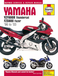
Руководство на английском языке по техническому обслуживанию и ремонту мотоциклов Yamaha FZS600 Fazer и YZF600R Thundercat 1996-2003 годов выпуска.
- Издательство: Haynes Publishing
- Год издания: —
- Страниц: 219
- Формат: PDF
- Размер: 12,1 Mb
Сервисная информация на английском языке для мотоциклов Yamaha моделей FZS600 и FZS600P 2002 года выпуска.
- Издательство: Yamaha Motor Co., Ltd.
- Год издания: 2001
- Страниц: 27
- Формат: PDF
- Размер: 4,1 Mb
Руководство на английском языке по ремонту мотоциклов Yamaha моделей FZS1000 и FZS1000N 2001 года выпуска.
- Издательство: Yamaha Motor Co., Ltd.
- Год издания: 2000
- Страниц: 403
- Формат: PDF
- Размер: 12,1 Mb

Сборник руководств на английском, французском, немецком, испанском и итальянском языках по ремонту мотоциклов Yamaha модели FZS1000 и др.
- Издательство: Yamaha
- Год издания: —
- Страниц: —
- Формат: ISO
- Размер: 1,7 Gb

-
Contents
-
Table of Contents
-
Troubleshooting
-
Bookmarks
Related Manuals for Yamaha Fazer FZS1000
Summary of Contents for Yamaha Fazer FZS1000
-
Page 1
OWNER’S MANUAL FZS1000 FZS1000S 5LV-28199-E2… -
Page 3
Please take the time to read this manual thoroughly, so as to enjoy all advantages of your FZS1000/FZS1000S. The owner’s manual does not only instruct you in how to operate, inspect and maintain your motorcycle, but also in how to safeguard yourself and others from trouble and injury. -
Page 4
This manual should be considered a permanent part of this motorcycle and should remain with it even if the motorcycle is subsequently sold. Yamaha continually seeks advancements in product design and quality. Therefore, while this manual contains the most current product information available at the time of printing, there may be minor discrepancies between your motorcycle and this manual. -
Page 5: Important Manual Information
IMPORTANT MANUAL INFORMATION EW000002 WARNING PLEASE READ THIS MANUAL CAREFULLY AND COMPLETELY BEFORE OPERATING THIS MOTORCYCLE.
-
Page 6
IMPORTANT MANUAL INFORMATION EAU04229 FZS1000/FZS1000S OWNER’S MANUAL ©2002 by Yamaha Motor Co., Ltd. 1st edition, May 2002 All rights reserved. Any reprinting or unauthorized use without the written permission of Yamaha Motor Co., Ltd. is expressly prohibited. Printed in Japan. -
Page 7: Table Of Contents
EAU00009 TABLE OF CONTENTS 1 GIVE SAFETY THE RIGHT OF WAY 2 DESCRIPTION 3 INSTRUMENT AND CONTROL FUNCTIONS 4 PRE-OPERATION CHECKS 5 OPERATION AND IMPORTANT RIDING POINTS 6 PERIODIC MAINTENANCE AND MINOR REPAIR 7 MOTORCYCLE CARE AND STORAGE 8 SPECIFICATIONS 9 CONSUMER INFORMATION INDEX…
-
Page 9: Give Safety The Right Of Way
GIVE SAFETY THE RIGHT OF WAY GIVE SAFETY THE RIGHT OF WAY ……….1-1…
-
Page 10
G IVE SAFETY THE RIGHT OF WAY EAU00021 Motorcycles are fascinating vehicles, which can give you an unsurpassed feeling of power and freedom. However, they also impose certain limits, which you must accept; even the best motorcycle does not ignore the laws of physics. Regular care and maintenance are essential for preserving value and operating condition of your motorcycle. -
Page 11: Description
DESCRIPTION Left view ………………… 2-1 Right view………………. 2-2 Controls and instruments …………..2-3…
-
Page 12: Left View
D ESCRIPTION EAU00026 Left view 1. Front fork compression 8. Seat lock/helmet holder (page 3-11/page 3-12) damping force adjusting screw (page 3-15) 9. Shock absorber assembly 2. Front fork rebound damping compression damping force force adjusting screw (page 3-14) adjusting screw (page 3-17) 3.
-
Page 13: Right View
DESCRIPTION Right view 13. Owner’s tool kit (page 6-1) 18. Engine oil filter cartridge (page 6-10) 14. Rear brake fluid reservoir (page 6-27) 19. Engine oil level check window (page 6-9) 15. Battery (page 6-35) 20. Brake pedal (page 3-9) 16.
-
Page 14: Controls And Instruments
DESCRIPTION Controls and instruments 1. Clutch lever (page 3-8) 6. Tachometer unit (page 3-5) 2. Left handlebar switches (page 3-7) 7. Fuel gauge (page 3-6) 3. Starter (choke) lever (page 3-11) 8. Right handlebar switches (page 3-7) 4. Speedometer unit (page 3-4) 9.
-
Page 15: Instrument And Control Functions
INSTRUMENT AND CONTROL FUNCTIONS Main switch/steering lock ……..3-1 Fuel tank cap …………3-9 Indicator and warning lights ……..3-2 Fuel …………..3-10 Speedometer unit ……….3-4 Fuel tank breather hose ……..3-11 Tachometer unit ………..3-5 Starter (choke) lever……….. 3-11 Self-diagnosis devices ………3-5 Seat …………..
-
Page 16: Main Switch/Steering Lock
I NSTRUMENT AND CONTROL FUNCTIONS EAU00027 NOTE: The headlights come on automatically when the engine is started and stay on until the key is turned to “OFF”, even if the engine stalls. EAU00038 All electrical systems are off. The key can be removed.
-
Page 17: Indicator And Warning Lights
INSTRUMENT AND CONTROL FUNCTIONS EAU04300 (Parking) The steering is locked, the taillights and auxiliary lights are on, and the hazard light can be turned on, but all other electrical systems are off. The key can be removed. The steering must be locked before the key can be turned to “…
-
Page 18
The electrical circuit of the warning light for a few seconds, then go off, have a can be checked by turning the key to Yamaha dealer check the electrical cir- “ON”. cuit. If the warning light does not come on… -
Page 19: Speedometer Unit
INSTRUMENT AND CONTROL FUNCTIONS This information will enable you to plan future fuel stops. To set a mode Push the “SELECT” button to change between the odometer mode “ODO”, and the tripmeter modes “TRIP 1” and “TRIP 2” in the following order: ODO →…
-
Page 20: Tachometer Unit
INSTRUMENT AND CONTROL FUNCTIONS To set the clock: EAU04290 Self-diagnosis devices 1. Push both the “SELECT” and This model is equipped with a self-di- “RESET” buttons for at least two agnosis device for the following electri- seconds. cal circuits: 2. When the hour digits start flashing, throttle position sensor push the “RESET”…
-
Page 21: Fuel Gauge
EAU00109 Anti-theft alarm (optional) ror code, note the circuit-specific num- This motorcycle can be equipped with ber of r/min, and then have a Yamaha an optional anti-theft alarm by a dealer check the motorcycle. Yamaha dealer. Contact a Yamaha EC000004 dealer for more information.
-
Page 22: Handlebar Switches
INSTRUMENT AND CONTROL FUNCTIONS EAU03889 Turn signal switch “ ” To signal a right-hand turn, push this switch to “ ”. To signal a left-hand turn, push this switch to “ ”. When released, the switch returns to the cen- ter position.
-
Page 23: Clutch Lever
INSTRUMENT AND CONTROL FUNCTIONS 1. Clutch lever 1. Shift pedal 1. Brake lever 2. Brake lever position adjusting dial EAU00152 EAU00157 3. Arrow mark Clutch lever Shift pedal a. Distance between brake lever and handlebar The clutch lever is located at the left The shift pedal is located on the left grip handlebar grip.
-
Page 24: Brake Pedal
INSTRUMENT AND CONTROL FUNCTIONS 2. Turn the key counterclockwise to the original position, remove it, and then close the lock cover. NOTE: The fuel tank cap cannot be closed un- less the key is in the lock. In addition, the key cannot be removed if the cap is not properly closed and locked.
-
Page 25: Fuel
INSTRUMENT AND CONTROL FUNCTIONS EAU00185 Your Yamaha engine has been de- CAUTION: signed to use regular unleaded gaso- Immediately wipe off spilled fuel line with a research octane number of with a clean, dry, soft cloth, since 91 or higher. If knocking (or pinging)
-
Page 26: Fuel Tank Breather Hose
INSTRUMENT AND CONTROL FUNCTIONS 1. Fuel tank breather hose 1. Starter (choke) lever “ ” 1. Seat lock 2. Original position (white mark) 2. Unlock. EAU03839 Starter (choke) lever “ ” EAU02955 EAU03956 Fuel tank breather hose Seat Starting a cold engine requires a richer Before operating the motorcycle: air-fuel mixture, which is supplied by Check the fuel tank breather hose…
-
Page 27: Helmet Holder
INSTRUMENT AND CONTROL FUNCTIONS 1. Projection 1. Helmet holder 2. Seat holder 2. Unlock. To install the seat EAU04291 Helmet holder 1. Insert the projection on the front of To open the helmet holder, insert the the seat into the seat holder as key into the seat lock, and then turn the shown.
-
Page 28: Storage Compartment
When storing the owner’s manual or This storage compartment is designed other documents in the storage com- to hold an optional genuine Yamaha partment, be sure to wrap them in a U-LOCK. (Other locks may not fit.) plastic bag so that they will not get wet.
-
Page 29
INSTRUMENT AND CONTROL FUNCTIONS 1. Spring preload adjusting bolt 1. Current setting 1. Rebound damping force adjusting screw 2. Front fork cap bolt Spring preload Rebound damping force To increase the spring preload and To increase the rebound damping NOTE: Align the appropriate groove on the ad- thereby harden the suspension, turn force and thereby harden the rebound… -
Page 30: Adjusting The Shock Absorber Assembly
INSTRUMENT AND CONTROL FUNCTIONS EC000015 EAU04295* Adjusting the shock absorber CAUTION: assembly Never attempt to turn an adjusting This shock absorber assembly is mechanism beyond the maximum equipped with a spring preload adjust- or minimum settings. ing ring, a rebound damping force ad- justing knob and a compression NOTE: Although the total number of clicks of a…
-
Page 31
INSTRUMENT AND CONTROL FUNCTIONS NOTE: Align the appropriate notch in the adjusting ring with the position in- dicator on the shock absorber. Use the special wrench included in the owner’s tool kit to make the ad- justment. CI-10E Setting 1. Spring preload adjusting ring 1. -
Page 32
7 clicks in direction a* Standard will result in poor damping per- 12 clicks in direction a* Maximum (hard) formance. * With the adjusting screw fully turned in direction b Always have a Yamaha dealer service the shock absorber. 3-17… -
Page 33: Exup System
Yamaha factory. Changing scribed below and have a Yamaha these settings without sufficient dealer repair it if it does not function technical knowledge may result properly. in poor performance of or dam- age to the engine.
-
Page 34: Ignition Circuit Cut-Off System
If a malfunction is noted, have a It prevents starting when the trans- Yamaha dealer check the sys- mission is in gear and the side- tem before riding. stand is up, but the clutch lever is not pulled.
-
Page 35
5. Push the start switch. Does the engine start? The neutral switch may be defective. The motorcycle should not be ridden until checked by a Yamaha dealer. With the engine still running: 6. Move the sidestand up. 7. Keep the clutch lever pulled. -
Page 37: Pre-Operation Checks
PRE-OPERATION CHECKS Pre-operation check list …………..4-1…
-
Page 38: Pre-Operation Check List
• If necessary, add recommended coolant to specified level. 6-12–6-13 • Check cooling system for leakage. • Check operation. • If soft or spongy, have Yamaha dealer bleed hydraulic system. Front brake • Check fluid level in reservoir. 6-26–6-27 • If necessary, add recommended brake fluid to specified level.
-
Page 39
• Make sure that operation is smooth. • Check cable free play. Throttle grip 6-19, 6-30 • If necessary, have Yamaha dealer adjust cable free play and lubricate cable and grip housing. • Make sure that operation is smooth. Control cables 6-30 •… -
Page 40
PRE-OPERATION CHECKS NOTE: Pre-operation checks should be made each time the motorcycle is used. Such an inspection can be accomplished in a very short time; and the added safety it assures is more than worth the time involved. EWA00033 WARNING If any item in the Pre-operation check list is not working properly, have it inspected and repaired before operating the motorcycle. -
Page 41: Operation And Important Riding Points
OPERATION AND IMPORTANT RIDING POINTS Starting a cold engine …………… 5-1 Starting a warm engine …………..5-3 Shifting ………………..5-3 Recommended shift points (for Switzerland only) ……5-4 Tips for reducing fuel consumption ……….. 5-4 Engine break-in …………….. 5-5 Parking ………………..5-5…
-
Page 42: Starting A Cold Engine
Before starting out, make sure should be on, otherwise have a Yamaha dealer check the electrical cir- that the sidestand is up. If the sidestand is not raised com- cuit. pletely, it could contact the 3.
-
Page 43: Operation And Important Riding Points
4. Start the engine by pushing the with sufficient engine oil, have a not come on for a few seconds, start switch. Yamaha dealer check the elec- then go off, or if it does not go trical circuit. off after starting with sufficient…
-
Page 44: Starting A Warm Engine
OPERATION AND IMPORTANT RIDING POINTS EAU01258 EC000048 Starting a warm engine CAUTION: Follow the same procedure as for start- Even with the transmission in ing a cold engine with the exception the neutral position, do not that the starter (choke) is not required coast for long periods of time when the engine is warm.
-
Page 45: Recommended Shift Points (For Switzerland Only)
OPERATION AND IMPORTANT RIDING POINTS EAU02937 EAU04577 Recommended shift points Tips for reducing fuel (for Switzerland only) consumption The recommended shift points during Fuel consumption depends largely on acceleration are shown in the table your riding style. Consider the following below.
-
Page 46: Engine Break-In
1,600 km and beyond The vehicle can now be operated normally. EC000053 CAUTION: Keep the engine speed out of the tachometer red zone. If any engine trouble should oc- cur during the engine break-in period, immediately have Yamaha dealer check the vehicle.
-
Page 47: Periodic Maintenance And Minor Repair
PERIODIC MAINTENANCE AND MINOR REPAIR Owner’s tool kit …………6-1 Checking and lubricating the throttle grip and cable …………… 6-30 Periodic maintenance and lubrication chart ..6-2 Checking and lubricating the brake and Removing and installing panels ……6-5 shift pedals …………6-31 Checking the spark plugs ……..6-7 Checking and lubricating the brake and Engine oil and oil filter cartridge ……6-9…
-
Page 48: Owner’s Tool Kit
Periodic inspection, adjustment and lu- ence required for a particular job, have brication will keep your vehicle in the a Yamaha dealer perform it for you. safest and most efficient condition pos- EW000063 sible. The most important points of in-…
-
Page 49: Periodic Maintenance And Minor Repair
The annual checks must be performed every year, except if a kilometer-based maintenance is performed instead. From 50,000 km, repeat the maintenance intervals starting from 10,000 km. Items marked with an asterisk should be performed by a Yamaha dealer as they require special tools, data and techni- cal skills.
-
Page 50
PERIODIC MAINTENANCE AND MINOR REPAIR ODOMETER READING (× 1,000 km) ANNUAL ITEM CHECK OR MAINTENANCE JOB CHECK • Check tread depth and for damage. • Replace if necessary. √ √ √ √ √ Tires • Check air pressure. • Correct if necessary. √… -
Page 51
PERIODIC MAINTENANCE AND MINOR REPAIR ODOMETER READING (× 1,000 km) ANNUAL ITEM CHECK OR MAINTENANCE JOB CHECK Front and rear brake √ √ √ √ √ √ • Check operation. switches √ √ √ √ √ Moving parts and cables • Lubricate. •… -
Page 52: Removing And Installing Panels
PERIODIC MAINTENANCE AND MINOR REPAIR 1. Panel A 1. Panel C 1. Panel A 2. Panel B 2. Screw EAU01122 EAU04003 Removing and installing Panels A and C To remove one of the panels panels Remove the screw, and then pull the The panels shown above need to be panel off as shown.
-
Page 53
PERIODIC MAINTENANCE AND MINOR REPAIR 1. Panel C 1. Panel B 2. Screw 2. Screw (× 3) To install the panel EAU01315 Place the panel in the original position, Panel B and then install the screw. To remove the panel Remove the screws, and then take the panel off. -
Page 54: Checking The Spark Plugs
Do not attempt to diagnose such problems yourself. Instead, have a Yamaha dealer check the motorcycle. 3. Check each spark plug for elec- trode erosion and excessive car- bon or other deposits, and replace 1.
-
Page 55
PERIODIC MAINTENANCE AND MINOR REPAIR 3. Install the spark plug with the spark plug wrench, and then tight- en it to the specified torque. Tightening torque: Spark plug: 12.5 Nm (1.25 m·kgf) NOTE: a. Spark plug gap If a torque wrench is not available when installing a spark plug, a good estimate To install a spark plug of the correct torque is 1/4–1/2 turn… -
Page 56: Engine Oil And Oil Filter Cartridge
PERIODIC MAINTENANCE AND MINOR REPAIR EAU04625 To change the engine oil (with or Engine oil and oil filter without oil filter cartridge replace- cartridge ment) The engine oil level should be checked 1. Start the engine, warm it up for before each ride.
-
Page 57
NOTE: An oil filter wrench is available at a Skip steps 4–6 if the oil filter car- Make sure that the O-ring is properly Yamaha dealer. tridge is not being replaced. seated. When draining the engine oil, use a funnel or similar device to keep the oil away from the exhaust pipe. -
Page 58
PERIODIC MAINTENANCE AND MINOR REPAIR 8. Add the specified amount of the ECA00133 CAUTION: recommended engine oil, and In order to prevent clutch slip- then install and tighten the oil filler page (since the engine oil also cap. lubricates the clutch), do not mix any chemical additives. -
Page 59: Coolant
If the oil level warning light flickers before each ride. In addition, the cool- or remains on, immediately turn the ant must be changed at the intervals engine off and have a Yamaha deal- specified in the periodic maintenance er check the vehicle. and lubrication chart.
-
Page 60
If water has been added to the coolant, have a Yamaha dealer check the antifreeze content of the coolant as soon as possible, otherwise the effectiveness of the coolant will be reduced. -
Page 61
PERIODIC MAINTENANCE AND MINOR REPAIR 8. Pour the recommended coolant into the radiator until it is full. Recommended antifreeze: High-quality ethylene glycol anti- freeze containing corrosion inhib- itors for aluminum engines Antifreeze/water mixture ratio: 1. Radiator cap 1. Coolant drain bolt Coolant quantity: 4. -
Page 62: Cleaning The Air Filter Element
12. Start the engine, and then check coolant, have a Yamaha dealer the vehicle for coolant leakage. If check the antifreeze content of coolant is leaking, have a Yamaha the coolant as soon as possible, dealer check the cooling system. otherwise the effectiveness of 13.
-
Page 63
PERIODIC MAINTENANCE AND MINOR REPAIR 1. Bolt (× 3) 1. Rubber cover 1. Air filter case cover 2. Rubber cover holder (× 2) 2. Screw (× 4) 2. Remove the fuel tank bolts. 5. Pull the rubber cover off its hold- 6. -
Page 64
PERIODIC MAINTENANCE AND MINOR REPAIR ECA00089* CAUTION: The engine should never be operat- ed without the air filter element in- stalled, otherwise the pistons and/or cylinders may become excessively worn. 10. Install the air filter case cover by installing the screws. 1. -
Page 65: Adjusting The Carburetors
The carburetors are important parts of the engine and require very sophisti- cated adjustment. Therefore, most car- buretor adjustments should be left to a Yamaha dealer, who has the neces- sary professional knowledge and expe- rience. The adjustment described in 1. Fuel tank breather hose the following section, however, may be 2.
-
Page 66: Adjusting The Engine Idling Speed
Yamaha dealer adjust it. Engine idling speed: 1,050–1,150 r/min NOTE: If the specified idling speed cannot be obtained as described above, have a Yamaha dealer make the adjustment. 6-19…
-
Page 67: Adjusting The Valve Clearance
2.50 bar) 2.70 bar) from occurring, the valve clearance regarding the specified tires. 250 kPa 290 kPa must be adjusted by a Yamaha dealer 90 kg–maximum (2.50 kgf/cm (2.90 kgf/cm 2.50 bar) 2.90 bar) at the intervals specified in the periodic…
-
Page 68
Yamaha dealer fied maximum load for the replace the tire immediately. vehicle. -
Page 69
PERIODIC MAINTENANCE AND MINOR REPAIR EW000079 EW000080 WARNING WARNING Have a Yamaha dealer replace The front and rear tires should excessively worn tires. Besides be of the same make and de- being illegal, operating sign, otherwise the handling motorcycle with… -
Page 70: Cast Wheels
Other tires may run fore each ride. If any damage is the danger of bursting at super CE-14E FRONT & REAR found, have a Yamaha dealer re- high speeds. Tire air valve TR412 place the wheel. Do not attempt…
-
Page 71: Adjusting The Clutch Lever Free Play
If the specified free play cannot be ob- tained as described above or if the clutch does not operate correctly, have a Yamaha dealer check the internal clutch mechanism. 1. Clutch lever free play adjusting bolt c. Clutch lever free play…
-
Page 72: Adjusting The Brake Pedal Position
If there is air in the hydraulic system, have a Yamaha dealer bleed the system be- fore operating the motorcycle. Air in the hydraulic system will diminish a. Distance between brake pedal and footrest 1.
-
Page 73: Checking The Front And Rear Brake Pads
The front and rear brake pads must be indicator groove has almost disap- checked for wear at the intervals spec- peared, have a Yamaha dealer replace ified in the periodic maintenance and the brake pads as a set. lubrication chart. Each brake pad is…
-
Page 74: Checking The Brake Fluid Level
Yamaha dealer ing it to become ineffective. Use only the recommended quali- check the cause.
-
Page 75: Changing The Brake Fluid
EAU03976 Changing the brake fluid Drive chain slack: 40–50 mm Have a Yamaha dealer change the brake fluid at the intervals specified in 5. If the drive chain slack is incorrect, the NOTE after the periodic mainte- adjust it as follows.
-
Page 76: Lubricating The Drive Chain
PERIODIC MAINTENANCE AND MINOR REPAIR EAU03006 NOTE: Lubricating the drive chain Using the alignment marks on each The drive chain must be cleaned and side of the swingarm, make sure that lubricated at the intervals specified in both chain pullers are in the same posi- the periodic maintenance and lubrica- tion for proper wheel alignment.
-
Page 77: Checking And Lubricating The Cables
If a cable is damaged the periodic maintenance chart. lubricants for the drive chain, as or does not move smoothly, have a they may contain substances that Yamaha dealer check or replace it. could damage the O-rings. Recommended lubricant: Engine oil EW000112…
-
Page 78: Checking And Lubricating The Brake And Shift Pedals
Recommended lubricant: Recommended lubricant: EW000114 WARNING Lithium-soap-based grease Lithium-soap-based grease If the centerstand or sidestand does (all-purpose grease) (all-purpose grease) not move up and down smoothly, have a Yamaha dealer check or re- pair it. 6-31…
-
Page 79: Lubricating The Rear Suspension
PERIODIC MAINTENANCE AND MINOR REPAIR EAU04282 Recommended lubricant: Lubricating the rear Lithium-soap-based grease suspension (all-purpose grease) The pivoting points of the rear suspen- sion must be lubricated at the intervals specified in the periodic maintenance and lubrication chart. Recommended lubricant: Lithium-soap-based grease 6-32…
-
Page 80: Checking The Front Fork
To check the operation If any damage is found or the front 1. Place the motorcycle on a level fork does not operate smoothly, surface and hold it in an upright have a Yamaha dealer check or re- position. pair it. 6-33…
-
Page 81: Checking The Wheel Bearings
Yamaha dealer check the wheel bearings. 2. Hold the lower ends of the front fork legs and try to move them for- ward and backward. If any free play can be felt, have a Yamaha dealer check repair steering.
-
Page 82: Battery
• EXTERNAL: Flush with plenty To charge the battery Battery of water. Have a Yamaha dealer charge the bat- This motorcycle is equipped with a • INTERNAL: Drink large quan- tery as soon as possible if it seems to sealed-type (MF) battery, which does tities of water or milk and im- have discharged.
-
Page 83: Replacing The Fuses
Turn signal light and hazard cess to a sealed-type (MF) bat- 6. Odometer and clock fuse (backup fuse) fuse: 10 A tery charger, have a Yamaha 7. Turn signal light and hazard fuse dealer charge your battery. 8. Spare fuse (× 2) EC000103 9.
-
Page 84: Replacing A Headlight Bulb
PERIODIC MAINTENANCE AND MINOR REPAIR 1. Headlight bulb cover 1. Headlight bulb holder 1. Do not touch the glass part of the bulb. 2. Headlight coupler 3. Unhook the headlight bulb holder, EW000119 EAU04226 WARNING and then remove the defective Replacing a headlight bulb Headlight bulbs get very hot.
-
Page 85
Take care not to damage the follow- 6. Install the panel. ing parts: 7. Have a Yamaha dealer adjust the Headlight bulb headlight beam if necessary. Do not touch the glass part of the headlight bulb to keep it free… -
Page 86: Replacing A Tail/Brake Light Bulb
PERIODIC MAINTENANCE AND MINOR REPAIR 1. Tail/brake light bulb cover 1. Socket 1. Screw 3. Remove the socket (together with EAU03961 EAU03497 Replacing a tail/brake light Replacing a turn signal light the bulb) by turning it counter- bulb bulb clockwise. 1.
-
Page 87: Front Wheel
4. Remove the brake caliper on each EW000122 side by removing the bolts. WARNING ECA00046 It is advisable to have a Yamaha CAUTION: dealer service the wheel. Do not apply the brake after the Securely support the motor- brake calipers have been removed,…
-
Page 88: Rear Wheel
EW000122 WARNING 5. Install the brake hose holders by installing the bolts. It is advisable to have a Yamaha 6. Tighten the wheel axle, the wheel dealer service the wheel. axle pinch bolt and the brake cali- Securely support the motor- per bolts to the specified torques.
-
Page 89
PERIODIC MAINTENANCE AND MINOR REPAIR 1. Bolt (× 2) 1. Axle nut 2. Brake torque rod 2. Drive chain slack adjusting bolt EAU03895 3. Brake torque rod bolt 3. Locknut To install the rear wheel 4. Brake torque rod nut 6. -
Page 90: Troubleshooting
7. Tighten the axle nut, brake caliper self. However, should your motorcycle bolts and brake torque rod nut to require any repair, take it to a Yamaha the specified torques. dealer, whose skilled technicians have the necessary tools, experience, and…
-
Page 91: Troubleshooting Charts
Remove the spark plugs and check the electrodes. The engine does not start. Have a Yamaha dealer check the vehicle. Check the battery. 4. Battery The engine turns over The battery is good.
-
Page 92
Start the engine. If the engine overheats again, have a The coolant level Yamaha dealer check and repair the cooling system. is OK. NOTE: If coolant is not available, tap water can be temporarily used instead, provided that it is changed to the recommended coolant as soon as possible. -
Page 93: Motorcycle Care And Storage
MOTORCYCLE CARE AND STORAGE Care ………………..7-1 Storage ………………..7-4…
-
Page 94
M OTORCYCLE CARE AND STORAGE EAU03426 Care Before cleaning Cleaning 1. Cover the muffler outlet with a ECA00010 While the open design of a motorcycle CAUTION: plastic bag after the engine has reveals the attractiveness of the tech- Avoid using strong acidic wheel cooled down. -
Page 95
MOTORCYCLE CARE AND STORAGE Do not use any harsh chemical For motorcycles equipped with After riding in the rain, near the sea or products on plastic parts. Be a windshield: Do not use strong on salt-sprayed roads sure to avoid using cloths or cleaners or hard sponges as Since sea salt or salt sprayed on roads sponges which have been in… -
Page 96
MOTORCYCLE CARE AND STORAGE ECA00012 After cleaning EWA00001 CAUTION: WARNING 1. Dry the motorcycle with a chamois Do not use warm water since it in- Make sure that there is no oil or or an absorbing cloth. wax on the brakes or tires. If creases the corrosive action of the 2. -
Page 97
NOTE: fuel tank. To prevent corrosion, avoid Consult a Yamaha dealer for advice on 4. Fill up the fuel tank and add fuel damp cellars, stables (because what products to use. stabilizer (if available) to prevent… -
Page 98
MOTORCYCLE CARE AND STORAGE a. Remove the spark plug caps 6. Lubricate all control cables and NOTE: Make any necessary repairs before and spark plugs. the pivoting points of all levers and storing the motorcycle. b. Pour a teaspoonful of engine pedals as well as of the sidestand/ oil into each spark plug bore. -
Page 99: Specifications
SPECIFICATIONS Specifications ………………8-1 Conversion table …………….8-5…
-
Page 100: Specifications
S PECIFICATIONS EAU01038 Specifications CS-01E Model FZS1000/FZS1000S Engine oil Dimensions Type -20 -10 10 20 30 40 50 ˚C Overall length 2,125 mm SAE 10W-30 Overall width 765 mm SAE 10W-40 Overall height 1,190 mm SAE 15W-40 Seat height 820 mm…
-
Page 101
SPECIFICATIONS Cooling system capacity Number of drive chain (total amount) 2.4 L sprocket teeth (front/rear) 16/44 Air filter Dry element Transmission type Constant-mesh 6-speed Fuel Operation Left foot Type REGULAR UNLEADED Gear ratio GASOLINE ONLY 2.500 Fuel tank capacity 21 L 1.842 Fuel reserve amount 1.500… -
Page 102
SPECIFICATIONS Rear Rear Type Tubeless tire Type Cast wheel 17 × MT 5.50 Size 180/55 ZR17 (73W) Size 17 M/C × MT 5.50 180/55 ZR17 M/C (73W) Manufacturer/ Brakes model METZELER / MEZ4Y Front Maximum load* 189 kg Type Dual disc brake Tire air pressure Operation Right hand… -
Page 103
SPECIFICATIONS Electrical system Fuses Ignition system T.C.I. (digital) Main fuse 30 A Charging system Headlight fuse 20 A Model A.C. magneto Radiator fan fuse 10 A Standard output 14 V, 365 W @ 5,000 r/min Ignition fuse 20 A Battery Signaling system fuse 20 A Model… -
Page 104: Conversion Table
SPECIFICATIONS EAU04513 Conversion table CS-04E Conversion table All specification data in this manual are listed in SI and METRIC SYSTEM TO IMPERIAL SYSTEM METRIC UNITS. Metric unit Conversion factor Imperial unit × m·kgf 7.233 ft·lbf × m·kgf 86.794 in·lbf Use this table to convert METRIC unit values to IMPERIAL Torque ×…
-
Page 105: Consumer Information
CONSUMER INFORMATION Identification numbers …………… 9-1 Key identification number …………..9-1 Vehicle identification number …………. 9-1 Model label ………………9-2…
-
Page 106: Identification Numbers
Record the key identification number, vehicle identification number and mod- el label information in the spaces pro- vided below for assistance when ordering spare parts from a Yamaha dealer or for reference in case the vehi- cle is stolen. 1. Key identification number 1.
-
Page 107: Model Label
The model label is affixed to the frame under the seat. (See page 3-11 for seat removal and installation procedures.) Record the information on this label in the space provided. This information will be needed when ordering spare parts from a Yamaha dealer.
-
Page 108
INDEX Air filter element, cleaning ……6-15 Dimmer switch……… 3-7 Identification numbers ……9-1 Anti-theft alarm ……..3-6 Drive chain, lubricating ……6-29 Ignition circuit cut-off system ….3-19 Drive chain slack ……..6-28 Indicator and warning lights……3-2 Adjusting ………. 6-29 Battery ………..6-35 Checking………. 6-28 Brake and clutch levers, checking and Key identification number ……9-1 lubricating ……….6-31… -
Page 109
INDEX Shifting ………… 5-3 Shift pedal ……….3-8 Valve clearance, adjusting ….6-20 Shift points (for Switzerland only)….. 5-4 Vehicle identification number….9-1 Shock absorber assembly, adjusting ..3-15 Sidestand ……….3-18 Wheel bearings, checking ….. 6-34 Spark plugs, checking ……6-7 Wheel (front) ……… -
Page 112
YAMAHA MOTOR CO., LTD. PRINTED ON RECYCLED PAPER PRINTED IN JAPAN 2002.06-0.3×1 CR…
(Ocr-Read Summary of Contents of some pages of the Yamaha FZS1000 Document (Main Content), UPD: 19 May 2023)
-
12, 2-1 2 EAU00026 2- DESCRIPTION Left view 1. Front fork compression damping force adjusting screw (page 3-15) 2. Front fork rebound damping force adjusting screw (page 3-14) 3. Front fork spring preload adjusting bolt (page 3-14) 4. Air filter element (page 6-15) 5. Fuses (page 6-36) 6. Storage compartment (page 3-13) 7. Grab bar 8. Seat lock/helmet holder (page 3-11/page 3-12) 9. Shock absorber assembly compression damping force adjusting screw (page 3-17) 10. Shock ab…
-
104, SPECIFICATIONS 8-5 8 EAU04513 Conversion table CS-04E All specification data in this manual are listed in SI and METRIC UNITS. Use this table to convert METRIC unit values to IMPERIAL unit values. Example: METRIC VALUE CONVERSION FACTOR IMPERIAL VALUE 2 mm × 0.03937 = 0.08 in Conversion table METRIC SYSTEM TO IMPERIAL SYSTEM Metric unit Conversion factor Imperial unit Torque m·kgf m·kgf cm·kgf cm·kgf × 7.233 × 86.794 × 0.…
-
68, PERIODIC MAINTENANCE AND MINOR REPAIR 6-21 6 EWA00012 WARNING _ Because loading has an enormous impact on the handling, braking, performance and safety characteris- tics of your motorcycle, you should keep the following precautions in mind. ● NEVER OVERLOAD THE MOTORCYCLE! Operation of an overloaded motorcycle may re- sult in tire damage, loss of con- trol, or severe injury. Make sure that the total weight of rider, passenger, cargo, and accesso- ries does not exceed the spe…
-
29, INSTRUMENT AND CONTROL FUNCTIONS 3-14 3 Spring preload To increase the spring preload and thereby harden the suspension, turn the adjusting bolt on each fork leg in di- rection a . To decrease the spring pre- load and thereby soften the suspension, turn the adjusting bolt on each fork leg in direction b . NOTE: _ Align the appropriate groove on the ad- justing mechanism with the top of the front fork cap bolt. _ CI-15E Rebound …
-
102, SPECIFICATIONS 8-3 8 Rear Type Tubeless tire Size 180/55 ZR17 (73W) 180/55 ZR17 M/C (73W) Manufacturer/ model METZELER / MEZ4Y Maximum load* 189 kg Tire air pressure (measured on cold tires) Up to 90 kg* Front 250 kPa (2.50 kgf/cm 2 , 2.50 bar) Rear 270 kPa (2.70 kgf/cm 2 , 2.70 bar) 90 kg–maximum* Front 250 kPa (2.50 kgf/cm 2 , 2.50 bar) Rear 290 kPa (2.90 kgf/cm 2 , 2.90 bar) High-speed riding Front 250 kPa (2.50 kgf/cm 2 , 2.50 bar) Rea…
-
90, Yamaha FZS1000 PERIODIC MAINTENANCE AND MINOR REPAIR 6-43 6 5. Install the brake caliper by install- ing the bolts. NOTE: _ Make sure that there is enough space between the brake pads before install- ing the brake caliper onto the brake disc. _ 6. Take the motorcycle off the cen- terstand so that the rear wheel is on the ground. 7. Tighten the axle nut, brake caliper bolts and brake torque rod nut to the specified torques. EAU03087 Troubleshooting Although Yamaha motor…
-
3, EAU04575 INTRODUCTION Welcome to the Yamaha world of motorcycling! As the owner of the FZS1000/FZS1000S, you are benefiting from Yamaha’s vast experience and newest technology regarding the design and manufacture of high- quality products, which have earned Yamaha a reputation for dependability. Please take the time to read this manual thoroughly, so as to enjoy all advantages of your FZS1000/FZS1000S. The owner’s manual does not only instruct you in how to operate, inspect …
-
85, PERIODIC MAINTENANCE AND MINOR REPAIR 6-38 6 EC000104 CAUTION: _ Take care not to damage the follow- ing parts: ● Headlight bulb Do not touch the glass part of the headlight bulb to keep it free from oil, otherwise the transpar- ency of the glass, the luminosi- ty of the bulb, and the bulb life will be adversely affected. Thor- oughly clean off any dirt and fin- gerprints on the headlight bulb using a cloth moistened with al- cohol or thinner. ● Headlight lens • Do not affix any type …
-
10, 1 1-1 EAU00021 1- GIVE SAFETY THE RIGHT OF WAY Motorcycles are fascinating vehicles, which can give you an unsurpassed feeling of power and freedom. However, they also impose certain limits, which you must accept; even the best motorcycle does not ignore the laws of physics. Regular care and maintenance are essential for preserving value and operating condition of your motorcycle. Moreover, what is true for the motorcycle is also true for the rider: good performance depends…
-
24, INSTRUMENT AND CONTROL FUNCTIONS 3-9 3 EAU00162 Brake pedal The brake pedal is on the right side of the motorcycle. To apply the rear brake, press down on the brake pedal. EAU02935 Fuel tank cap To open the fuel tank cap Open the fuel tank cap lock cover, in- sert the key into the lock, and then turn it 1/4 turn clockwise. The lock will be re- leased and the fuel tank cap can be opened. To close the fuel tank cap 1. Push the fuel tank cap into posi- tion with the key inserted in the …
-
86, Yamaha FZS1000 PERIODIC MAINTENANCE AND MINOR REPAIR 6-39 6 EAU03961 Replacing a tail/brake light bulb 1. Remove the seat. (See page 3-11 for seat removal and installation procedures.) 2. Remove the tail/brake light bulb cover. 3. Remove the socket (together with the bulb) by turning it counter- clockwise. 4. Remove the defective bulb by pushing it in and turning it counter- clockwise. 5. Insert a new bulb into the soc…
-
101, Yamaha FZS1000 SPECIFICATIONS 8-2 8 Cooling system capacity (total amount) 2.4 L Air filter Dry element Fuel Type REGULAR UNLEADED GASOLINE ONLY Fuel tank capacity 21 L Fuel reserve amount 4 L Carburetor Manufacturer MIKUNI Model × quantity BSR37 × 4 Spark plug Manufacturer/type NGK / CR9E or DENSO / U27ESR-N Gap 0.7–0.8 mm Clutch type Wet, multiple-disc Transmission Primary reduction system Spur gear Primary reduc…
-
5, IMPORTANT MANUAL INFORMATION EW000002 WARNING _ PLEASE READ THIS MANUAL CAREFULLY AND COMPLETELY BEFORE OPERATING THIS MOTORCYCLE. _ U5LVE2.book Page 2 Thursday, June 27, 2002 5:23 PM
… -
70, PERIODIC MAINTENANCE AND MINOR REPAIR 6-23 6 CE-10E CE-14E EAU00684 WARNING _ This motorcycle is fitted with super- high-speed tires. Note the following points in order to make the most ef- ficient use of these tires. ● Use only the specified replace- ment tires. Other tires may run the danger of bursting at super high speeds. ● Brand-new tires can have a rela- tively poor grip on certain road surfaces until they have been “broken in”. Therefore, it is ad- …
-
95, MOTORCYCLE CARE AND STORAGE 7-2 7 ● Do not use any harsh chemical products on plastic parts. Be sure to avoid using cloths or sponges which have been in contact with strong or abrasive cleaning products, solvent or thinner, fuel (gasoline), rust re- movers or inhibitors, brake flu- id, antifreeze or electrolyte. ● Do not use high-pressure wash- ers or steam-jet cleaners since they cause water seepage and deterioration in the following ar- eas: seals (of wheel and…
-
56, PERIODIC MAINTENANCE AND MINOR REPAIR 6-9 6 EAU04625 Engine oil and oil filter cartridge The engine oil level should be checked before each ride. In addition, the oil must be changed and the oil filter car- tridge replaced at the intervals speci- fied in the periodic maintenance and lubrication chart. To check the engine oil level 1. Place the motorcycle on the cen- terstand. NOTE: _ Make sure that the motorcycle is posi- tioned straight up when checkin…