-
Contents
-
Table of Contents
-
Troubleshooting
-
Bookmarks
Quick Links
USE AND MAINTENANCE
NUO
Gas Analyzer
Related Manuals for Seitron Novo
Summary of Contents for Seitron Novo
-
Page 1
USE AND MAINTENANCE Gas Analyzer… -
Page 3: Table Of Contents
TABLE OF CONTENTS IMPORTANT INFORMATION Information about this manual Danger levels and other symbols SAFETY Safety check Intended purpose Improper use of the product Precautions for the usage of the Li-Ion battery package GENERAL OVERVIEW PRODUCT DESCRIPTION Working principle Measurement sensors 4.3 CO dilution (if the configuration allows it) Autozero…
-
Page 4
18.1 Spare parts 18.2 Accessories 18.3 Service Centers ANNEX A — «Seitron Smart Analysis» APP ANNEX B — Analysis report ANNEX C — Optional measures list ANNEX D — Coefficient of the fuels and Formulas WARRANTY CERTIFICATE TROUBLESHOOTING J100000000S9 037479 220721… -
Page 5: Important Information
IMPORTANT INFORMATION Information about this manual ◊ This manual describes the operation and the characteristics and the maintenance of the Combustion Analyzer. ◊ Read this operation and maintenance manual before using the device. The operator must be familiar with the manual and follow the instructions carefully. ◊ This use and maintenance manual is subject to change due to technical improvements — the manufacturer assumes no responsibility for any mistakes or misprints. Respect your environment: think before printing the full manual on paper. Danger levels and other symbols WARNING! The magnets in the back of the instrument can damage credit cards, hard driver, mechanical watches, pacemakers, defibrillators and other devices proven sensitive to magnetic fields.
-
Page 6: Safety
Safety check Use the product according to what is described in chapter “Intended purpose”. During the instrument operation, comply with the current standards. Do not use the instrument if damaged on the outer cover, on the power supply plug or on the cables. Do not take measures on non-isolated components / voltage conductors. Keep the instrument away from solvents. For the maintenance of the instrument, strictly comply with what’s described in this manual at the “Maintenance” chapter. All the interventions not specified in this manual, may be performed exclusively by Seitron Americas assistance centers. Otherwise, Seitron Americas declines every responsibility about the normal operation of the instrument and on the validity of the several homologations. Intended purpose This chapter describes the areas of application for which the Novo is intended. Using the Novo in other application areas is on the risk of the operator and the manufacturer assumes no responsibility and liability for loss, damage or costs which could be a result. It is mandatory to read and pay attention to the operating/maintenance manual. All products of the series Novo are handheld measuring devices in professional flue gas analysis for: • Furnaces (burning oil, gas, wood, coal) • Low-temperature and condensing boilers • Gas heaters • Engines •…
-
Page 7: General Overview
— Impact protection system integrated on the instrument case. — Ticket printing through printer module integrated in the instrument (if the instrument configuration provides for it) or via an external Bluetooth® printer (optional). — QR code generation in order to download the analysis / measures data shown on the display, having previously installed the special APP “SEITRON SMART ANALYSIS” available on play-store and Apple iOS App store. — Connectivity with a computer through the USB connection and/or Bluetooth®. Once the special software provided with the instrument is used, this allows for the storage of combustion analysis as well as the configuration of the main parameters. — Connectivity with a smartphone through Bluetooth®. Once the specific APP “SEITRON SMART ANALYSIS” available on Google play-store is installed on the device, the user can start remote analysis of combustion and/or view real-time data of the analysis in progress. Main functions: — Combustion analysis in manual or automatic mode (according to the data logger function, user-defined mode). — Comes with most used fuel parameters (such as natural gas, LPG, gas oil and fuel oil). — Possibility to store in memory the parameters for additional further fuels, once their chemical composition is known. — Monitoring of pollutants (emissions). — Memory capable of storing up to 2,000 full analysis.
-
Page 8
— Smoke test (with the use of the external manual pump) — Gas pressure in the piping — Combustion air measurement — Auxiliary temperatures — Air speed for air or flue gas leaving the chimney with the use of Pitot tube Maintenance All the sensors installed on the instrument can be replaced by the user, as long as the sensor is on the same installation position as the previous one. -
Page 9: Product Description
PRODUCT DESCRIPTION Working principle The gas sample is taken in, through the flue gas probe, by a membrane pump inside the instrument. The probe is featured with a sliding fitting-cone that allows the probe itself to be inserted into holes with a diameter from 11 mm to 16 mm, and to set the immersion depth: the smoke pick-up point must approximately correspond to the center of the satck. The gas sample which must be analyzed must be taken to the measurement sensors dehumidified and purified from solid combustion residues. In order to achieve this, a water trap is used, which is a transparet plastic cylinder placed inside the instrument. Its purpose is to decrease the speed of the air in order to precipitate the heavier dust particles and condense the vapor contained in the combustion gases.
-
Page 10: Autozero
Any potential drift of the sensor are nulled thanks to the autozeroing system. Printer If the configuration allows it, the instrument is featured with a printer module permanently attached to the instrument and so the user can print the results of the measurements on a ticket that certifies the system performaces. If the instrument does not include the printer module, this can be installed at a later time by sending the instrument to a Seitron service center. Alternatively, a remote Bluetooth® printer can be associated with the instrument. In both cases, through the special parameter which is visible on the home page of the instrument, it is possible to select the printer to use (internal or external) and to set the related printing settings.
-
Page 11: Calibration Certificate
PC Connection With the provided USB cable or in Bluetooth (optional) mode it is possible to connect the instrument to a personal computer with Microsoft Windows 7 o later operative system, after installing the appropriate software “Seitron Smart Analysis“, which can be downloaded from the website www.seitronamericas.com. 4.16 Bluetooth® connection The analyzer is internally equipped with a Bluetooth® module, which allows the communication with the following remote devices: — Bluetooth® printer — Smartphone or tablet of latest generation on which the Google Android v.5.0 (Jelly Bean) or latter operative system is installed, after installing the proper “Seitron Smart Analysis” APP available on Google Play store. — PC with Microsoft Windows 7 or later operative system and Bluetooth® connection after installing the proper software “Seitron Smart Analysis” which can be downloaded from the website www.seitronamericas.com. The maximum transmission range in open field is 100 meters, with the condition that the connected device has a Bluetooth® class 1 connection. This solution allows superior operator freedom of movement, who is not directly connected to the instrument for acquisition and analysis operations, with remarkable advantages for many applications. Available Software and applications. 4.17 Available applications and software •…
-
Page 12: Mechanical Description
MECHANICAL DESCRIPTION Front view Printer module On / Off power button Lid to access the paper roll of the printer Probe inputs USB type C interface, for connecting the instrument to a personal computer or to the battery charger. User interface * This component is present only if the instrument model is featured with the internal printer module.
-
Page 13: Back View
Back view Magnets Water trap low level notch Water trap / filter assembly Water trap high level notch Gas output J100000000S9 037479 220721…
-
Page 14: Inputs
Inputs (T2) Tc-K female connector (T1) Female connector Tc-K Connection for air temperature probe Tc-K Tc-K input male connector for the flue probe. male connector. (P3) Male pneumatic connector Female pneumatic connector for water trap/ Pneumatic input for gas valve pressure filter assembly.
-
Page 15: Using The Flue Gas Analyser
Remove the instrument from its packing and check it for damage. Make sure that the content corresponds to the ordered items. If signs of tampering or damage are noticed, notify that to the Seitron Americas service center or agent immediately and keep the original packing The serial number and model of the instrument are shown in the data plate of the instrument.
-
Page 16: Use With External Power Pack
6.2.2 Use with external power pack The instrument can work with the batteries fully drained by connecting the external power pack provided. WARNING! THE POWER SUPPLY/BATTERY CHARGER IS A SWITCHING TYPE ONE. THE APPLICABLE INPUT VOLTAGE RANGES BETWEEN 90Vac AND 264Vac. INPUT FREQUENCY: 50-60Hz. THE LOW VOLTAGE OUTPUT IS 5 VOLT WITH AN OUTPUT CURRENT GREATER THAN 1.5A. LOW VOLTAGE POWER CONNECTOR: A-TYPE USB CONNECTOR + CONNECTION CABLE WITH C-TYPE PLUG.
-
Page 17: Instrument Home Page
6.3.1 Instrument home page Once the instrument has been switched on, the display shows the home page screen. Carry out the complete combustion analysis. Also, access the analysis configuration menu; the user can set the different reference parameters of the instrument to carry out the combustion analysis. FOR ALL DETAILS, REFER TO CHAPTER 8.0. Enters the Operator menu.
-
Page 18: Warning
Warning • Use the instrument with an ambient temperature between 23 °F and 113 °F (-5 and +45°C). WARNING! IF THE INSTRUMENT HAS BEEN KEPT AT VERY LOW TEMPERATURES (BELOW OPERATING TEMPERATURES) WE SUGGEST WAITING A WHILE (1 HOUR) BEFORE SWITCHING IT ON TO HELP THE SYSTEM’S THERMAL BALANCE AND TO PREVENT CONDENSATE FORMING IN THE PNEUMATIC CIRCUIT.
-
Page 19: Positioning Of The Instrument During Operation
Firmato digitalmente Firmato digitalmente Data : 23/07/2021 Data : 23/07/2021 elettronico) senza l’autorizzazione scritta di SEITRON S.p.A. a socio unico elettronico) senza l’autorizzazione scritta di SEITRON S.p.A. a socio unico Modello 3D : WC3D00705 D : WC3D00705 J100000000S9 037479 220721…
-
Page 20: Connection Diagram
CONNECTION DIAGRAM Flue gas and combustion air temperture probe connection diagram Part # AASA08 Part # AJSJ01 Part # AJPT— J100000000S9 037479 220721…
-
Page 21: Probe Connection For Simultaneous Pressure, O2, Combustion Parameters And Efficiency Calculation
Probe connection for simultaneous pressure, O2, combustion parameters and efficiency calculation Part # AJTB01 Part # AJSJ01 Part # AJPT— J100000000S9 037479 220721…
-
Page 22: Pc Connection
PC connection J100000000S9 037479 220721…
-
Page 23: Flue Gas Analysis
FLUE GAS ANALYSIS To perform complete flue gas analysis, follow the instructions below. Warnings WARNING! FOR A CORRECT ANALYSIS NO AIR MUST FLOW INTO THE PIPE FROM OUTSIDE DUE TO A BAD TIGHTENING OF THE CONE OR A LEAK IN THE PIPELINE. THE GAS PIPE MUST BE CHECKED IN ORDER TO AVOID ANY LEAKAGES OR OBSTRUCTIONS ALONG THE PATH.
-
Page 24
already present) and screwing in the positioning cone provided with the probe — in this way no air is drawn from the outside during sampling. The screw on the cone allows the probe to be stopped at the right measuring depth — this usually corresponds to the centre of the exhaust pipe. For greater positioning accuracy, the user may insert the probe gradually into the pipe until the highest temperature is read. The exhaust pipe must be inspected before carrying out the test, so as to ensure that no constrictions or losses are present in the piping or stack. -
Page 25: Setting The Main Analysis Parameters
Setting the main analysis parameters After inserting the flue gas probe in the stack and, if necessary, set up any probe to measure the combustion air temperature in the special pick-up manifold, you can proceed, if not previously done, to the configuration of the analysis mode setting the requested data: J100000000S9 037479 220721…
-
Page 26: Analysis Parameters
8.4.1 Analysis parameters Through this menu the user can configure the available parameters for a proper combustion analysis. PARAMETER FUNCTION Lets the user select the type of fuel to be used during analysis. By selecting the sub menu Fuel coefficients the user can view the characteristics of Fuel the fuels used in the calculation of performance The burner efficiency figure when condensation takes place is influenced by atmospheric pressure and humidity of the combustion air.
-
Page 27
The CO sensor is protected by a pump which, in case of need, can inject clean air in the gas path in order to dilute the gas concentration measured by the sensor. This function can be either triggered by the overcoming of a CO concentration threshold which can be set by the user or, in case it is known that the flue gases contain high CO concentration, kept enabled any time, independently of CO concentration. CO Dilution WARNING! CO AUTO-DILUTION FEATURE MUST ONLY BE CONSIDERED… -
Page 28: Start And End Of The Combustion Analysis In Manual Mode
Start and end of the combustion analysis in manual mode Turns on / off the sampling probe. If the pump is switched off, the refresh of the current measures is freezed. Pressed for the first time it starts the analysis, but it doesn’t acquire any measure. When it is pressed afterwards, at each press acquires the current measure.
-
Page 29: Starting The Combustion Analysis On Automatic Mode (Data Logger Mode)
Starting the combustion analysis on automatic mode (Data Logger mode) Turns on / off the sampling probe. If the pump is switched off, the refresh of the current measures is freezed. Starts the combustion analysis in accordance with the set analysis parameters. Pause the current analysis.
-
Page 30: Ending The Combustion Analysis On Automatic Mode (Data Logger Mode)
8.6.1 Ending the combustion analysis on automatic mode (Data Logger mode) Turns on / off the sampling probe. If the pump is switched off, the refresh of the current measures is freezed. Starts the combustion analysis in accordance with the set analysis parameters. LAST ANALYSIS: Date and time of the last performed analysis.
-
Page 31: End Of Analysis
End of analysis — At the end of the combustion analysis, carefully remove the sample probe and remote air temperature probe, if used, from their relative ducts, taking care not to get burnt. — Switch off the instrument by pressing the On/Off key. At this point, if the instrument has detected a high concentration of CO and/or NO, a self-cleaning cycle will be initiated during which the pump will draw fresh outside air until the gas levels drop below acceptable values. The duration of the cleaning cycle depends on the setting made in the Configuration menu. Note: However, it is always advisable to purge the instrument with clean air for at least 5 — 10 minutes, before turning it off and in any case check that the measured value is lower than 20ppm.
-
Page 32: Operator
OPERATOR In this menu you can select the operator who carries out the combustion analysis or other measurements, which will be saved and / or printed on the analysis report. The menu, which cannot be modified by the user, has 5 generic operators associated with an avatar. It will be the customer’s responsibility to match the operator’s name to the relevant avatar in the menu. Daniel Seig Robert Gham Jacob Smith Michael Black Tyler Gill J100000000S9 037479 220721…
-
Page 33: 10.0 Measurements
10.0 MEASUREMENTS This combustion analyzer is able to perform several other measurements, accessible from the home page of the instrument in the «Measurements» menu. MEASURE REFERENCE CHAPTER Draft 10.1 Smoke test 10.2 Ambient CO 10.3 Temperature 10.4 Pressure 10.5 P gas 10.6 Cercafughe di gas combustibile 10.7…
-
Page 34: Draft Measurement
10.1 Draft measurement This menu allows you to measure the stack draft. WARNING! The measurement may not be accurate due to condensation inside the gas probe. Should you notice an inaccurate or unstable reading on the instrument, it is advisable to disconnect the gas probe from the instrument itself, and purge pipes by blowing with a compressor. In order to be sure there is no humidity, it is suggested to perform the measurement by means of the transparent rubber pipe supplied on issue.
-
Page 35: P Gas» Measures Network Gas Pressure
10.6 “P gas” Measures network gas pressure It is possible, using an external tube, to connect to P3 input and measure the inlet pressure of the network gas within the range set on P3 at chapter 18 “Measurement and accuracy ranges. 10.7 Cercafughe di gas combustibile THIS MENU IS AVAILABLE ONLY IF THE SENSOR FOR GAS LEAKSISINSTALLED IN THE INSTRUMENT. It allows to identify gas leaks in plants, in pipes and in the devices. To perform the test it is required to have installed the specific internal semiconductor sensor for gas leaks detection and the relevant probe with flexible hose and metal tip, which allows to withdraw the gas in a localised point even in areas with very small leaks. The sensor is sensitive to both CH4 (Methane) and LPG (IsoButane and IsoPropane) as well as several other combustible gases (hydrocarbons).
-
Page 36: 11.0 Settings
11.0 SETTINGS The configuration menu is featured with all the reference parameters of the instrument, the information about the instrument status and the diagnostic, in order to check any anomalies. PARAMETER REFERENCE CHAPTER Instrument 11.1 Operator 11.2 Information 11.3 Diagnostic 11.4 Autozero 11.5 J100000000S9 037479 220721…
-
Page 37: Instrument Configuration
11.1 Instrument configuration 11.1.1 Bluetooth® Through this sub menu the user can turn on and off the instrument Bluetooth® wireless and visualize the MAC address of the instrument. When the Bluetooth® is powered, on the “ “ icon is shown on the diasplay. WARNING! WHEN THE INSTRUMENT BLUETOOTH INTERFACE IS TURNED ON, THE BATTERY LIFE IS REDUCED DOWN TO 10 HOURS. 11.1.2 Time/Date This allows the current time and date to be set. The user can select the date and hour format. 11.1.3 Brightness This submenu allows to adjust the brightness of the display. 11.1.4 Language Sets the instrument language. 11.1.5 Country Selecting a different country from the one selected at the first startup of the instrument, will automatically change the time format and language.
-
Page 38: Diagnostic
11.4 Diagnostic The user, through this menu, can check any instrument anomalies. 11.4.1 FW update This menu is not accessible by the user because it is strictly reserved for the assistance centers. 11.4.2 Maintenance The parameters in this menu are not accessible to the user as they are for the exclusive use of the assistance centers. 11.4.3 Pump In this submenu the user can temporarily turn the gas suction pump on or off.
-
Page 39
By selecting a sensor, on the recalibration screen are shown all the information related to the latest calibration. DATA FUNCTIONALITY Calibrate saves new calibration not active: returns to the factory calibration Status active: returns to the last calibration made by the user —- no ‘on site calibration’… -
Page 40
OXIGEN SENSOR (O ) CALIBRATION DETAIL 5. The calibration is possible only when the status is set to ‘—-’ (sensors that have never been calibrated before) otherwise it is necessary to set the status on ‘non active’ (see example below). 6. Apply gas to the instrument and adjust the output pressure of the gas from the cylinder so that the flow meter indicates a minimum flow of 0.5 l/m: : this guarantees that the instrument is taking the exact amount of gas required by the internal pump. -
Page 41
SENSOR CALIBRATION DETAIL FOR TOXIC GASES (EXAMPLE REFERRED TO CO) 5. The calibration is possible only when the status is set to ‘—-’ (sensors that have never been calibrated before) otherwise it is necessary to set the status on ‘non active’. 6. Enter the value of the concentration of the gas applied. 7. -
Page 42
SENSOR CALIBRATION DETAIL FOR TOXIC GASES WITH INTERFERING GASES The sensors for toxic gases with interfering gases are those sensors which are sensible to other gases. The on-site calibration for these sensors allows to calibrate also the interfering gases. The on-site calibration procedure for these sensors is the same described on the previous pages regarding the toxic gases and can be performed for all the interfering gases of the sensor itself. Follow the instructions on the display carefully. -
Page 43: Sensors
11.4.5 Sensors This menu is protected by a Password. The user password is the following: “1111”. This menu shows the four positions of the sensors. On each position is shown the kind of installed sensor, any error and the symbol “ “ to access more information on the selected sensor. For example, if the instrument shows “S1: CO” it means that on position 1 the CO sensor is installed. For each sensor installed it is possible to access the related identification data: DATA DESCRIPTION Gas detected by the sensor. Type Sesnor revision index. Measure range Sensor measuring range. Serial Serial number of the sensor. ‘Is’ sensor current. ‘Ia’…
-
Page 44: Leak Test
11.4.6 Leak test Tests the tightness of the gas probe pneumatic path. To proceed with the leak test of the gas probe, proceed as indicated in the following points: 1. Connect the flue gas sampling probe and filter unit assembly to the instrument; 2. Fully insert the black rubber cap on the gas probe tip, as shown in the following picture: 3. Follow the directions on the display. 4. At the end of the procedure the instrument shows the test results: Tight: The system is OK. Error: The system has a leak. Check that the probe is tightly connected to the instrument, check the gaskets of the pneumatic connectors and/or the gaskets of the water trap / filter assembly and check that the special black cap is well inserted on the probe. WARNING: the tip of the probe, if damaged, might distort the test. 11.5 Autozero In this submenu you can change the duration of the analyzer autozero cycle and the duration of the automatic cleaning cycle. 11.5.1 Autozero In this submenu you can change the duration of the analyzer autozero cycle, expressed in seconds.
-
Page 45: 12.0 Print
12.0 PRINT The analyzer can print a report ticket with the results of all the preformed measures, according to the settings made in this menu. The printing is carried out with the internal printer module, if the instrument is provided with it, or using an external printer with Bluetooth® communication. PARAMETER REFERENCE CHAPTER Printer 12.1 Configuration 12.2 Measurement list 12.3 Print test 12.4 Paper feed 12.5 J100000000S9 037479 220721…
-
Page 46: Printer
12.1 Printer Allows to choose the kind of printer, internal (Int) or external (Ext) with Bluetooth® communication. If you choose the external printer will be necessary to perform the pairing procedure to pair the Bluetooth® printer to the instrument. 12.1.1 Pairing BT Through this sub menu, the user can access to the association procedure between the instrument and a Bluetooth® printer. The pairing procedure has to be done only once. 1. Enter the menu Pairing BT, turn on the printer which you want to connect to the instrument. 2. Select the line corresponding to the desired Bluetooth® printer. 3. The instrument automatically associates the selected printer. 4. The display shows “Device connected”; the operation is completed. 5. Return to the previous screen. WARNING! — It is possible to associate multiple Bluetooth®…
-
Page 47: Measurement List
12.3 Measurement list In this submenu it is possible to show the list of the measures which the instrument can perform and which will be printed on the tickets, if enabled. If a measurement is disabled it will not be printed even if acquired in the combustion analysis phase. Another important function available in this submenu, is sorting the list of measurements using the appropriate interactive function. Measurement enabled — will be printed on Measure disabled — it will NOT be printed on ticket.
-
Page 48: 13.0 Archive
13.0 ARCHIVE All the performed combustion analyses/measures are saved in the instrument archive. J100000000S9 037479 220721…
-
Page 49: Archive Organization
13.1 Archive organization Select the folders visualization mode in the Example of viewing the archive by customer archive. name. Memory Usage: The yellow bar indicates «Search» function: search by text or by date. the used memory space. Change the archive view to: CUSTOMER: Folders are displayed per customer.
-
Page 50: Maintenance
14.0 MAINTENANCE 14.1 Preventive maintenance At least once a year send the instrument to a SERVICE CENTER for a complete overhaul and thorough internal cleaning. Seitron Americas’ highly qualified staff is always at your disposal and will provide you with all the sales, technical, application and maintenance details required. The service center will always return the instrument to you as new and in the shortest time possible. Calibration is performed using gases and instruments comparable with National and International Specimens. Annual servicing is accompanied by a specific calibration certificate that is a guarantee of perfect instrument performance, besides being indispensable for users wishing to maintain ISO 9000 status. 14.2 Routine maintenance This instrument was designed and manufactured using top-quality components. Proper and systematic maintenance will prevent the onset of malfunctions and will increase instrument life altogether. The following basic requisites are to be respected: • Do not expose the instrument to substantial thermal shocks before use. If this happens, wait for the temperature to return to normal working values. • Do not clean the instrument with abrasive cleaners, thinners or other similar detergents. • Avoid to suck in smokes directly without the filter inserted inside the water trap / filter assembly unit. • Do not exceed sensor overload thresholds. • When the analysis is over extract the sample probe from the stack and let the analyzer draw fresh air for a few minutes, or at least until the displayed parameters return to their original values: O2: > 20.0% Toxic gases: <20ppm • It is a good rule to empty the water trap / filter assembly unit at the end of every complete analysis or at least every 2 — 3 complete analyses.
-
Page 51: Maintenance For The Water Trap / Filter Assembly Unit
14.2.2 Maintenance for the water trap / filter assembly unit Through the side opening, it is possible to verify the level of the water trap, by checking the notches on the side of the analyzer and the condition of the dust filter. Particulate filter Upper level notch Lower level notch WARNING! — To check the condensation level, hold the instrument upright. — Do not use the instrument with the condensation level between the two notches. — Do not use the instrument with a blackened filter or clogged with moisture, so as not to obstruct the flow of gas.
-
Page 52
To perform maintenance, it is necessary to remove the entire water trap / filter assembly unit from the instrument, as indicated below: 1. The instrument must be switched off. 2. Using the special flaps, turn left the water trap unit. 3. Pull out the entire unit. Draining the water trap 4. Separate the water collector from the entire unit. 5. Empty the water collector and clean it with water. 6. Place back on the water collector by reversing the operations described above. J100000000S9 037479 220721… -
Page 53
Replacing the dust filter If the dust filter is black or dirty, especially on the outer surface, or clogged with humidity it is necessary to replace it immediately: 7. Turn right the filter holder. 8. Pull off the filter. 9. Clean with just water and dry all the plastic parts of the case holding the filter, separating it before the water collector (see point 4). 10. Insert the new filter. 11. Reassemble the filter holder body by proceeding in the reverse order up to here described. J100000000S9 037479 220721… -
Page 54: Instrument Internal Parts Access
14.2.3 Instrument internal parts access WARNING! Access the internal parts only if strictly necessary to perform the gas sensors replacement or battery replacement. Before accessing the internal parts, the instrument must be switched off and must NOT be connected to mains power with the power plug. When managing the instrument without the cover, be sure not to lose the screws.
-
Page 55: Sensor Replacement
14.2.4 Sensor replacement All sensors installed on the instrument can be replaced directly by the user, as long as the same installation position of the previous sensor is maintained. 14.2.5 Replacing of the sensors In order to replace a sensor proceed as follows (example referred to the sensor installed in position S2): 1. Check the current position of the sensor to be replaced: Through the menu “Instrument configuration=> Diagnostic=> Sensors” check the current position of the : S2.
-
Page 56
4. Insert the new sensor by doing the reverse operation described up to here. The new sensors are provided with two O-rings; be sure that these O-rings are well inserted inside the special groove of the sensor (see the example in the picture below). Insert the new sensor into the rails and push down until fully seated. 5. -
Page 57: Battery Replacement
14.2.6 Battery replacement In order to replace the battery package proceed as described below: 1. Remove the battery connector. 2. Remove the battery pack. 3. Insert the new battery; in order to close back the instrument, reverse the operations described above. J100000000S9 037479 220721…
-
Page 58
14.2.7 Replacing the paper roll of the internal printer (if provided) To replace the printer paper roll, follow the operations described below. 1. Open the paper roll compartment lid, pulling upward the two sockets indicated by the arrows: 2. Fully raise the entire lid lock. 3. Insert the printer paper roll as shown in the following pictures. 4. Close the entire printer cover assembly, applying a slight pressure on it in order to hook it to the instrument. 5. Now you can use the printer. See the chapter «Print». -
Page 59: Instrument Expandability
3. Connect the analyzer to the PC via the USB cable. 4. Open the software “Seitron Smart Analysis” and make the login with e-mail address and password; if you are at the first access you need to register. If the software is not installed on the PC, it is necessary to download it from the website www.seitron.it at the section “Download — App and Software”. Click on the «USB» icon.
-
Page 60: 15.0 Gas Sensors
Scala del Foglio : 1:5 Nessuna parte di questo documento può essere riprodotta in alcuna forma (compresa la copia fotostatica o la memorizzazione su qualsiasi supporto Firmato digitalmente Data : 23/07/2021 elettronico) senza l’autorizzazione scritta di SEITRON S.p.A. a socio unico J100000000S9 037479 220721…
-
Page 61: Cxhy Sensor For Measurement Of The Unburnt Hydrocarbons
15.2 CxHy sensor for measurement of the unburnt hydrocarbons The unburnt hydrocarbons are chemicals produced by an incomplete combustion of molecules (hydrocarbons) made of Carbon and Hydrogen. These are usually named as HC or (better) CxHy: when this is filled with the actual values for the number of C and H atoms, the actual type of fuel is exactly defined. In case of Methane, as an example, the correct formula is CH4. In the following table is shown the cross sensitivity of the CxHy sensor when exposed to fuels different from Methane (CH4), assumed as 1.00. RELATIVE RESPONSE GAS / VAPOR GAIN ADJUSTMENT (with respect to Methane) Ethanol 0.75 1.33…
-
Page 62: 16.0 Technical Specifications
16.0 TECHNICAL SPECIFICATIONS Autozero: Automatic autozero cycle with probe inserted in the stack. Dilution (where required): Measure range expansion system of the CO sensor up to 100.000ppm (10,00%) programmable as simple protection of the CO sensor, user programmable intervention threshold. Gas measurement sensors: Up to 4 configurable sensors: electrochemical, NDIR and pellistors. Probe connection: Using a solid and robust connector it is possible to measure smokes values, temperature and draft at the same time. Self-diagnosis: Check of all functions and internal sensors with anomalies report. Temperature measurement: Double input for K thermocouple with mignon connector for measuring the differential pressure (output and input). Ambient temperature measurement: Using the internal sensor or the T2 thermocouple input with remote probe. Gas valve pressure measurement: Using a pressure sensor and a direct connection to the gas valve with a dedicated tube it is possible to perform this measurement simultaneously with the other combustion control measures (input P3).
-
Page 63: Analyzer Dimensions
Firmato digitalmente Data : 05/05/2021 (compresa la copia fotostatica o la memorizzazione su qualsiasi supporto elettronico) senza l’autorizzazione scritta di SEITRON S.p.A. a socio unico Firmato digitalm elettronico) senza l’autorizzazione scritta di SEITRON S.p.A. a socio unico Modello 3D : WC3D00705 18.3071 in (465 mm)
-
Page 64: 17.0 Measurement And Accuracy Ranges
17.0 MEASUREMENT AND ACCURACY RANGES MEASUREMENT RANGE RESOLUTION ACCURACY RESPONSE TIME RECALIBRATION AVERAGE POSITION LIFE 0.1% vol ±0.2% vol 20 s. Yearly 48 months S4 0-25% Vol. Yearly 48 months S1 1 ppm ±10 ppm 0…200 ppm 50 s. 0-8000 ppm ±5% m.v. 201…2000 ppm compensated H2 ±10% m.v. 2001…8000 ppm Yearly 48 months S1 — S2 — S3 -…
-
Page 65
MEASUREMENT RANGE RESOLUTION ACCURACY RESPONSE TIME RECALIBRATION AVERAGE POSITION LIFE Pressure (P3) -100.0 .. 500.0 hPa 0.01 hPa ±1% m.v. -2.01 .. -100.0 hPa ±0.02 hPa -2.00 .. +2.00 hPa ±1% m.v. +2.01 .. +500.00 hPa Air index 0.00 .. 9.50 0.01 Excess air (“e”) 0 .. 850 % Stack loss 0.0 .. 100.0 % 0.1 % Efficiency 0.0 .. -
Page 66: 18.0 Spare Parts And Servicing
10 ft extension cable for gas sampling probe AA SP01 Protective screen for gas sampling probe AAFS02 Inox filter with adapter 18.3 Service Centers Seitron Americas Inc. 4622 E. Street Rd. Trevose, PA 19053 — USA Tel.: (215) 660-9777 Fax.: (215) 660-9770 E-mail: service@seitronamericas.com http://www.seitronamericas.com J100000000S9 037479 220721…
-
Page 67: Annex A — «Seitron Smart Analysis» App
ANNEX A — «Seitron Smart Analysis» APP Data Management with “SEITRON SMART ANALYSIS” APP. SCAN THE QR CODE USING SEITRON APP “SEITRON SMART ANALYSIS”, TO DOWNLOAD THE ACQUIRED DATA. Novo THE ACQUIRED DATA ARE SAVED IN THE INSTRUMENT MEMORY. APP settings. REFERENCE SETTING Insert a default email address. Select the data separation mode: comma (,) or semicolon (;).
-
Page 68
Louis C. Novo S1500-NP REFERENCE SETTING Insert an email address if different from the default one. Select one of the two modes of data sharing. Select the file format to share. Select the application to use for sending. Example of the exported csv file and imported in an excel file: Novo Serial number… -
Page 69: Annex B — Analysis Report
15 ppm Sign.: ______________ Ref. O2: 0.0 % Ref. O2: 0.0 % CO ref 92 ppm CO ref 92 ppm Novo Ref. O2: 0.0 % Ref. O2: 0.0 % Serial: 999989 NO ref 52 ppm NO ref 52 ppm Ref. O2: 0.0 %…
-
Page 70
Park Road, 9 Time: 10.15 Tel.02/12345678 Fuel: Natural gas Oper.: John Smith Altitude: 0 m R.H. air: 50 % Sign.: ______________ 15.7 % Novo 2.9 ppm Serial: 999989 4.01 T gas 177.08 °F Date: 05/05/2021 T air 80.42 °F Time: 10.30 68.5 %… -
Page 71
Park Road, 9 Tel.02/12345678 Tel.02/12345678 Tel.02/12345678 Oper.: John Smith Oper.: John Smith Oper.: John Smith Sign.: ______________ Sign.: ______________ Sign.: ______________ Novo Novo Novo Serial: 999989 Serial: 999989 Serial: 999989 Date: 05/05/2021 Date: 05/05/2021 Date: 05/05/2021 Time: 10.30 Time: 10.30 Time: 10.30… -
Page 72: Annex C — Optional Measures List
ANNEX C — Optional measures list MEASURE DEFINITION Air index (defined as λ, sometimes also indicated as n). λ, n (l,n) E (Exc. Air) Air excess. Expressed as a percentage according to the formula in the appendix B, is the ratio between the volume of air actually entering the combustion chamber and the one theoretically needed. Differential temperature: ΔT (dT) It is the difference between the smoke temperature and the air combustion temperature. Loss sens Stack losses in relation to the Lower Heating Value (LHV): It is the percentage of dissipated heat through the stack referred to the lower heating value (LHV).
-
Page 73
MISURA DEFINIZIONE CO (REF) CO quantity measurement with O2 reference. Measurement units: ppm — mg/m3 — mg/kWh — g/GJ — g/m3 — g/kWh — % — ng/J CO amb. ext. Measure of the outer CO level when using the external CO probe. Measurement unit: ppm. This is the only measurement unit which is possible to set. WARNING! OTHER THAN THE MEASUREMENT LIST ABOVE, IT IS POSSIBLE TO VISUALIZE THE MEASURE OF THE DETECTED GAS ALSO IN PPM, DEPENDING ON THE KIND OF MEASUREMENT SENSOR IN THE INSTRUMENT. IF IT IS NECESSARY TO MEASURE THE VALUE OF GAS WITH TWO DIFFERENT MEASUREMENT UNITS, SELECT IN THE MEASUREMENTS LIST THE DESIRED GAS IN PPM AND CHANGE THE MEASUREMENT UNIT FOR THE SAME GAS IN THE “CONFIGURATION->ANALYSIS->MEASUREMENT UNIT”… -
Page 74: Annex D — Coefficient Of The Fuels And Formulas
ANNEX D — Coefficient of the fuels and Formulas The following chart lists the coefficients of the memorised fuels, used for calculating losses and efficiencies. Coefficients for calculating combustion efficiency Fuel A1 USA CO2t M air M H2O V gas dry (KJ/Kg) (KJ/Kg) (Kg/Kg) (Kg/Kg) /Kg) Natural Gas 0.0280 0.0090 11.70 50050 55550 17.17 2.250 11.94 #2 Oil 0.0305 0.0066…
-
Page 75: Warranty Certificate
48 months from purchasing date. Seitron undertakes to repair or replace, free of charge, those parts that, in its opinion, are found to be faulty during the warranty period. The products which are found defective during the above mentioned periods of time have to be delivered to Seitron Laboratories carriage paid. The following cases are not covered by this warranty: accidental breakage due to transport, inappropriate use or use that does not comply with the indications in the product’s instruction leaflet. Any mistreatment, repairs and modifications to the product not explicitly authorized by Seitron shall invalidate the present warranty. IMPORTANT For the product to be repaired under Warranty, please send a copy of this Certificate along with the instrument to be repaired, together with a brief explanation of the fault observed. Space reserved for user Name: Company: User’s notes: Serial number (S.N.): Date: Seitron Americas Inc. 4622 Street Rd. Trevose, PA 19053 — USA Tel: (215) 660-9777 — Fax: (215) 660-9770 — service@seitronamericas.com — www.seitronamericas.com J100000000S9 037479 220721…
-
Page 76
J100000000S9 037479 220721… -
Page 77: Troubleshooting
TROUBLESHOOTING SYMPTOM PROBABLE CAUSES AND REMEDIES a. Keep the On/Off key depressed for at least 3 seconds. The instrument does not work at all. When the On/Off pushbutton is pressed the instrument does not come b. The battery is low; connect the battery charger to the instrument. c. The battery may not be connected to the instrument; Access the internal parts and insert the battery connector into its socket on the printed circuit (see chapter 15.2.3 and 15.2.6). d. The instrument is faulty: Contact the assistance center. The batteries last less than 8 hours. a. Battery capacity is limited by low temperatures. To achieve a longer battery life it is recommended to store the instrument at higher temperatures.
-
Page 78
The built-in printer of the instrument does not print correctly. a. Check the type of paper you are using as it should only be thermal paper. b. Check the direction of the paper roll. c. If the paper is not dragged, check the closure of the printer door and the integrity of the feed roller. -
Page 79
J100000000S9 037479 220721… -
Page 80
Seitron Americas Inc. 4622 Street Rd. Trevose, PA 19053 — USA Tel: (215) 660-9777 Fax: (215) 660-9770 service@seitronamericas.com — www.seitronamericas.com…
Сигнализатор Seitron RGDMETMP1 это электронный прибор, удовлетворяющий всем требованиям по безопасности во всех случаях, когда использование бытовых и промышленных установок влечет за собой риск образования утечек природного газа.
Сигнализатор представляет собой стационарный, одноканальный автоматический прибор непрерывного действия с одним фиксированным порогом, со световой и звуковой сигнализацией.
Сигнализатор Seitron RGDMETMP1 предназначен для определения повышенной концентрации природного газа, выдачи сигнализации о превышении установлен- ного порогового значения довзрывоопасной концентра- ции природного газа в воздухе, а также для выдачи сигнала на приточно-вытяжную вентиляцию или на электромагнитный газовый клапан для прекращения подачи газа посредством замыкания (размыкания) контактов реле.
Принцип действия сигнализатора – термокаталитический, основанный на измерении сопротивления нагретой платиновой спирали, величина которого пропорциональна тепловому эффекту реакции окисления (горения) природного газа, протекающего на каталитически активированной поверхности этой спирали. Способ забора пробы – диффузионный. Рабочее положение сигнализатора – вертикальное.
Область применения сигнализатора – невзрывоопасные зоны жилых (кухни), коммунально-бытовых, административных и общественных зданий, а также невзрывоопасные зоны производственных зданий и сооруже- ний с применением газоиспользующего оборудования (котельные различной мощности).
Конструктивно сигнализатор выполнен одноблочным в пластмассовом корпусе с встроенным датчиком и предназначен для крепления на стену.
При срабатывании сигнализатор обеспечивает возможность осуществлять коммутацию внешних цепей контактами реле типа «сухой контакт» для автоматического включения (отключения) исполнительных устройств.
Принцип работы сигнализатора:
При обнаружении утечки газа и достижении уровня 10% от объема нижней границы взрывоопасной концен- трации звучит звуковой сигнал, а на лицевой панели загорается красный индикатор. Если концентрация газа длится более 7 секунд переключаются контакты выход- ного реле, к которым может быть подключен газовый отсечной клапан.
При снижении концентрации ниже порогового значения 10%/20% НКПР индикатор перестает све-ся,звукой сигнал затихает, а контакты реле возвращаются в исходное положение автоматически.
К сигнализатору Seitron RGDMETMP1 может быть подключен один внешний сенсор типа SGAMET. В случае обнаружения утечки газа в зоне установки внешнего сенсора на передней панели сигнализатора красный индикатор мигает.
Запрещается проверять работоспособность сигнализатора газом из зажигалок !
На лицевой панели сигнализатора расположены световые индикаторы, имеющие следующие обозначения:
- зеленый — питание, нормальная работа
- желтый — отказ чувствительного элемента
- красный — авария
На лицевой панели расположена также кнопка «test», нажатие и удержание которой в течение 2 сек запускает функцию тестирования чувствительного элемента и всего сигнализатора в целом.
Монтаж сигнализатора:
Сигнализатор Seitron RGDMETMP1 устанавливается на высоте 30-40 см от потолка, над местами возможных утечек газа, в местах возможных скоплений газа, в местах удобных для обслуживания. Для доступа к клеммной колодке снимите лицевую панель.
Избегайте установку сигнализатора в помещении с присутствием таких веществ как, растворители, клеи, лакокрасочная продукция, парфюмерная продукция, алкоголь.
Работоспособность прибора напрямую зависит от его местоположения. Не рекомендуется устанавливать сигнализатор в замкнутом пространстве (в шкафу), рядом с дверью или окном, в местах с повышенной влажностью, в местах, где пыль и грязь могут блокировать работу чувствительного элемента, а также в местах, где температура может опускаться ниже -10°С или повышаться свыше +50°С.
Рекомендуется по мере необходимости протирать чувствительный элемент и корпус сигнализатора тканью, смоченной спиртосодержащим раствором, при этом прибор должен быть отключен от электроэнергии.
Запрещается проверять работоспособность сигнализатора газом из зажигалок !
Технические характеристики сигнализатора загазованности на природный газ (метан) Seitron RGDMETMP1:
| Параметр | Значение |
|---|---|
| Напряжение питания | 230V~ ±10% 50Гц |
| Потребляемая мощность | 6 ВА |
| Тип датчика | SnO2 полупроводник |
| Время прогрева не более |
30 сек |
| Порог срабатывания | 10% НКПР |
| Погрешность | ±5% НКПР |
| Детектируемый газ | Метан |
| Мощность контактов реле | 6(2) А @ 250V~ SPDT |
| Срок службы датчика | 5 лет |
| Рабочая температура | 0°С…+40°С |
| Рабочая влажность | 20%…80% ОВ (без конденсата) |
| Температура хранения | -10°С…+50°С |
| Степень защиты | IP42 |
| Размеры | 148х84х40 (ДхВхШ) |
| Вес | ~300 гр. |
сигнализатор метана (СН4), серия SEGUGIO
| Отбор: | диффузионный |
| Минимальная канальность и количество контролируемых газов: | 1 |
| Максимальная канальность: | 2 |
| Тип сенсора: | термохимический |
| Газы: | метан, |
| Пылевлагозащита: | IP42, IP30 (для внешнего сенсора SGAMET) |
| Взрывозащита: | не предусмотрена |
| Выходные сигналы: | «сухие» контакты реле |
| Индикация: | световая и звуковая |
| Единицы измерения: | % НКПР |
| Рабочий диапазон температур: | от 0°С до 50°С |
| Питание: | от сети 230В, возможно 12В за дополнительную плату и под заказ |
| Габариты, мм: | 148х84х40 мм |
| Масса, кг: | 0,3 кг |
| Гарантийный срок: | 2 года |
| Поверка: | прибор поставляется с поверкой |
| Межповерочный интервал: | 1 год |
 |
Цена от 9300 до 15100 руб. с НДС В НАЛИЧИИ |
| Наименование | Цена с НДС, руб. |
|---|---|
| Комплект Сейтрон (Seitron) RGDМЕTМР1 с внешним сенсором SGAMET на метан, порог 10% НКПР или 20% НКПР | 15100 |
| Сигнализатор Сейтрон (Seitron) RGDМЕТМР1 на метан, порог 10 %НКПР (20 %НКПР под заказ) | 9300 |
Посмотреть все ценыЗаказать
Сигнализатор RGDMETMP1 Seitron (Сейтрон) предназначен для определения повышенной концентрации природного газа (метана), выдачи сигнализации о превышении установленного порогового значения довзрывоопасной концентрации (ДВК) природного газа (метана) в воздухе, а также для выдачи сигнала на приточно-вытяжную вентиляцию или на электромагнитный газовый клапан для прекращения подачи газа посредством замыкания (размыкания) контактов реле.
Принцип действия — термокаталитический.
Способ забора пробы — диффузионный.
Область применения RGDMETMP1 — невзрывоопасные зоны жилых (кухни), коммунально-бытовых, административных и общественных зданий и сооружений с применением газоиспользующего оборудования (котельные различной мощности).
Принцип работы
При обнаружении утечки газа и достижении уровня 10% (20% по запросу) от объема нижней границы взрывоопасной концентрации звучит звуковой сигнал, а на лицевой панели загорается красный индикатор. Если концентрация газа длится более 7 секунд переключаются контакты выходного реле, к которым может быть подключен газовый отсечной клапан. При снижении концентрации ниже порогового значения 10% (20%) НКПР индикатор перестает светиться, звуковой сигнал затихает, а контакты реле возвращаются в исходное положение автоматически.
Для контроля загазованности природным газом (СН4) в двух точках к сигнализатору RGDMETMP1 может быть подключен один внешний сенсор SGAMET. В случае обнаружения утечки газа в зоне установки внешнего сенсора на передней панели сигнализатора мигает красный индикатор.
Сигнализатор RGDМЕТМР1 Seitron (Сейтрон) снабжен системой автодиагностики. Мигающий желтый индикатор на лицевой панели (аварийная сигнализация) информирует о неисправности чувствительного элемента. Проверка работы выходных реле, индикации и звуковой сигнализации прибора RGDMETMP1 осуществляется нажатием (не менее 5 с) контрольной кнопки на лицевой панели. Для блокировки сигнализатора необходимо нажать кнопку «Тест» на лицевой панели кратковременно, при этом происходит блокировка сирены и реле на 10 минут.
Технические характеристики RGDМЕТМР1 Seitron (Сейтрон) серии SEGUGIO
| Характеристики | Значения |
|---|---|
| Напряжение питания | 230 В±10% |
| Потребляемая мощность | 3ВА |
| Выходные сигналы | реле, 6 (2) А / 250В |
| Тип сенсора | термокаталитический |
| Срок службы датчика | 5 лет |
| Световая сигнализация : — зеленый светодиод — желтый светодиод — красный светодиод> |
рабочее состояние неисправность тревога |
| Звуковая тревога | 85дБ |
| Порог срабатывания | 10±5 %НКПР (под заказ 20 %НКПР) |
| Температура хранения | от -10°С до 50°С |
| Степень защиты корпуса | IP42 |
| Габаритные размеры, мм | 148х84х40 |
| Масса, кг | 0,3 |
| Условия эксплуатации | |
| Температура окружающей среды | от 0°С до +50°С |
| Относительная влажность воздуха | 30% — 85% (без конденсатора) |
Согласно требованиям нормативных документов, количество необходимых датчиков в системе загазованности рассчитывается исходя из формулы — 1 датчик на 100 м2 для горючих газов (метан), но не менее 1-го датчика на помещение. Сигнализатор RGDМЕТМР1 устанавливается в верхней части помещения, над местами возможной утечки газа в местах удобных для обслуживания.
Преимущества сигнализатора RGDMETMP1 Seitron (Сейтрон)
- возможность подключения выносного сенсора SGAMET;
- порог срабатывания 10 % НКПР (или 20% по запросу);
- прибор прост и понятен при эксплуатации, легкий монтаж;
- самодиагностика сенсора обеспечивает наивысший уровень безопасности персонала;
- возможность в любой момент протестировать работу прибора нажатием кнопки ТЕСТ;
- безотказная работа прибора в течение длительного времени, низкая стоимость обслуживания;
- легкая замена чувствительного элемента, без пайки;
- гарантийный срок 2 года.
Схема подключения RGDМЕТМР1 Seitron (Сейтрон)

Схема соединения RGDМЕТМP1 и нормально-закрытого клапана EVG NC

Схема соединения RGDМЕТМР1 с внешним сенсором SGAMET,
с нормально-закрытым клапаном EVGNC и электронной сиреной ACCSRL220

Схема соединения RGDМЕТМР1 с внешним сенсором SGAMET,
с нормально-открытым клапаном EVGNA и электронной сиреной ACCSRL220

Схема соединения сигнализаторов RGDCO0MP1 и RGDMETMP1,
с нормально-открытым клапаном EVGNA и электронной сиреной ACCSRL220
![]()
Схема соединения сигнализаторов RGDCO0MP1 и RGDMETMP1,
с нормально-закрытым клапаном EVGNC и электронной сиреной ACCSRL220

Схема соединения сигнализаторов RGDМЕТМР1 с RGICO0L42,
с нормально-закрытым клапаном EVGNC и электронной сиреной ACCSRL220

Схема соединения сигнализаторов RGDМЕТМР1 с RGICO0L42,
с нормально-открытым клапаном EVGNA и электронной сиреной ACCSRL220

Схема подключения RGDМЕТМР1 Seitron (Сейтрон) к аккумулятору ACCSGB6A

* — Положение контактов реле указано при включенном электропитании и отсутствии загазованности.
Максимальная ДЛИНА ЛИНИИ СВЯЗИ с сенсором SGAMET — 30 м.
Марка кабеля — экранированный кабель сечением не менее 0,75 мм2.
Все цены на сигнализатор RGDMETMP1 Seitron (Сейтрон) указаны с учетом стоимости первичной государственной поверки.
Цены на сайте в процессе обновления!!! Актуальную стоимость уточняйте запросом на e-mail: zakaz@kipkomplekt.ru
Прайс-лист:
| Наименование | Цена без НДС, руб. | Цена с НДС, руб. |
|---|---|---|
| Комплект Сейтрон (Seitron) RGDМЕTМР1 с внешним сенсором SGAMET на метан, порог 10% НКПР или 20% НКПР | 12583 | 15100 |
| Сигнализатор Сейтрон (Seitron) RGDМЕТМР1 на метан, порог 10 %НКПР (20 %НКПР под заказ) | 7750 | 9300 |
| Дополнительное оснащение | Цена без НДС, руб. | Цена с НДС, руб. |
| Аккумуляторная батарея ACCSGB6A, обеспечивающая резервное питание сигнализатора Seitron RGDМЕТМР1 | 12250 | 14700 |
| Сейтрон (Seitron) SGAMET внешний сенсор загазованности на метан (порог срабатывания — 20 %НКПР), IP30, поверяется совместно с Сейтрон RGDMETMP1 | 4833 | 5800 |
| Электронная сирена ACCSRL220 громкость звука — 70dB, мощность лампы — 25W, напряжение питание 230V~ -15% +10% 50Гц | 15250 | 18300 |
| ЗИП к прибору | Цена без НДС, руб. | Цена с НДС, руб. |
Предусмотрены скидки в зависимости от количества заказываемого оборудования. Для того чтобы узнать точную цену, присылайте заявки на e-mail gaz@kipkomplekt.ru или на факс (347) 246-43-34 с обратными контактными данными.
Доставка приборов осуществляется по территории Российской Федерации посредством транспортных компаний «Деловые линии» и «ЖелДорЭкспедиция», в отдельных случаях — службами доставки «Даймекс» или «PONY EXPRESS».
На всю представленную продукцию распространяются гарантийные обязательства Завода — Производителя.
Описание
Предназначен для постоянного контроля за повышенной концентрацией метана (CH4) в воздухе рабочей зоны производственных помещений и выдачи сигнализации о превышении пороговых значений срабатывания, а также для передачи управляющего сигнала на вентиляционное оборудование или на электромагнитный газовый клапан для перекрытия подачи природного газа посредством замыкания (размыкания) контактов реле.
Сигнализатор RGD MET MP1 (Seitron, Италия) выполнен в одноблочном пластмассовом корпусе и представляет собой прибор газового анализа стационарного автоматического типа непрерывного действия с диффузионным отбором пробы с одним фиксированным порогом.
К сигнализатору есть возможность подключения дополнительного внешнего сенсора SGAMET на CH4.
Газосигнализатор имеет светозвуковую сигнализацию, а также имеет реле 6 (2) А / 250В.
Газосигнализатор оборудован системой автоматической диагностики. Мигающий жёлтый индикатор на лицевой панели прибора (аварийная сигнализация) оповещает о неисправности встроенного датчика TGS 2611.
Прибор состоит из элементов:
1. Блок питания и сигнализации со встроенным полупроводниковым газочувствительным сенсором на метан (TGS2611 Figaro);
2. Один выносной датчик природного газа – SGAMET (по отдельному заказу).
Газосигнализатор RGDMETMP1 является средством измерения, внесён в Государственный реестр средств измерений и поставляется Покупателю с обязательной первичной заводской поверкой.
Согласно требованиям РД 10-319-99 «Типовая инструкция по безопасному ведению работ для персонала котельных», количество необходимых приборов в системе загазованности рассчитывается исходя из формулы — 1 сигнализатор на 100 м2 для горючих газов (метана), но не менее 1-ого сигнализатора на помещение. Приборы на размещают в верхней части помещения под потолком на высоте 20 см от потолка (т.к. метан легче воздуха), над местами возможных утечек газа, в местах возможных скоплений газа, в местах удобных для обслуживания.
НЕ РЕКОМЕНДУЕТСЯ устанавливать прибор в следующих метах и условиях:
• в местах с повышенной влажностью;
• в замкнутом пространстве (в шкафу);
• в помещениях, где температура может опускаться ниже -10°С или повышаться свыше +50°С;
• рядом с дверью или окном;
• в местах, где грязь и пыль могут блокировать работу газочувствительного датчика;
• в помещении с присутствием таких веществ как, клеи, парфюмерная продукция, растворители, лакокрасочная продукция, алкогольная продукция.
Доставка по России, Казахстану, Беларуси, Киргизии и Армении
Торговый дом УЭТ осуществляет доставку товаров по всей России и странам Таможенного Союза. Мы сотрудничаем с заводами напрямую, поэтому оборудование будет доставлено к вам в максимально быстрые сроки минуя транзитные склады. Клиенты в Екатеринбурге могут воспользоваться услугой бесплатной доставки по городу или услугой самовывоза с нашего склада.
Доставка в другие города осуществляется транспортными компаниями Деловые Линии и DPD, в другие страны — DPD. Если у вас есть предпочтения по отправке груза другой транспортной компанией, пожалуйста предупредите об этом вашего менеджера. Вы можете воспользоваться услугой доставки как до терминала, так и по адресу, в том числе на строящиеся объекты.
![]()
© 1999 — 2019 ВИСА-М | Теплоснабжение, водоснабжение, канализация | Главная | info@visa-m.ru
Поставка, монтаж и сервисное обслуживание систем теплоснабжения, водоснабжения и канализации.
Монтаж котельных, котельного оборудования, реконструкция котельных.
![]()
 7900
7900
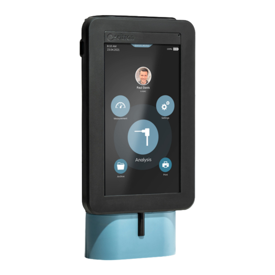
ЦИФРОВОЙ ПОРТАТИВНЫЙ ИЗВЕЩАТЕЛЬ УТЕЧКИ ГАЗА
- Работает от аккумуляторной батареи Li-Po 3,6 В — 2 Ач
- Настраиваемые пользователем параметры
- Акустическая и оптическая индикация в случае тревоги
- Функция автоматического отключения


ОБЪЯВЛЕНИЕ
Это устройство представляет собой цифровой портативный детектор утечки газа, оснащенный внешним штырем (для достижения точки, в которой вероятна утечка), на конце которого установлен газовый полупроводниковый датчик для обнаружения низких концентраций углеводородов в газовых приборах и трубах. .
 ПРЕДУПРЕЖДЕНИЕ!
Это устройство не является измерительным инструментом.
Это устройство может обнаруживать либо метан (CH4), либо сжиженный нефтяной газ (смесь изобутана и изопропана, но обычно несколько типов углеводородов).
Концентрация газа отображается на 4-разрядном ЖК-дисплее, а также в виде гистограммы в диапазоне от 0 до 100% полной шкалы. Прибор оснащен функциями автоматического обнуления и самоотключения.
ПИТАНИЕ ДЕТЕКТОРА
Детектор оснащен внутренним перезаряжаемым аккумулятором Li-Po.
Подзарядка производится путем подключения внешнего источника питания (5В, мин.0,5А/ч – не предусмотрено) к разъему USB Type B. В случае необходимости можно перезарядить
аккумулятор детектора, подключив его к ПК или с помощью блока питания, если он имеет выходное напряжение 5 вольт и минимальный ток 0,5 А/ч. ПРЕДУПРЕЖДЕНИЕ!
ИНСТРУМЕНТ ПОСТАВЛЯЕТСЯ СО СРЕДНИМ УРОВНЕМ ЗАРЯДА АККУМУЛЯТОРА, РЕКОМЕНДУЕТСЯ ВЫПОЛНИТЬ ПОЛНЫЙ ЦИКЛ ЗАРЯДА АККУМУЛЯТОРА, КОТОРЫЙ ПРОДОЛЖАЕТСЯ 4 ЧАСА. РЕКОМЕНДУЕТСЯ ПРОИЗВОДИТЬ ПЕРЕЗАРЯДКУ ПРИ ТЕМПЕРАТУРЕ ОКРУЖАЮЩЕЙ СРЕДЫ, НАХОДЯЩЕЙСЯ В ДИАПАЗОНЕ 10 °C .. 30 °C.
Устройство оснащено двумя светодиодами, расположенными на передней крышке, которые отображают следующую информацию при зарядке аккумуляторной батареи:
| КРАСНЫЙ СВЕТОДИОД (1) | ЗЕЛЕНЫЙ СВЕТОДИОД (2) | |
| Идет зарядка аккумулятора | On | от |
| Зарядка аккумулятора завершена | от | On |
| Аккумулятор не работает или сломан. | On | On |
ТЕХНИЧЕСКИЕ ОСОБЕННОСТИ
| Источник питания: | Аккумуляторный блок Li-Po 3,6В, 2Ач |
| Внешний источник питания: | 5В, мин. 0,5А/ч |
| Разъем питания: | USB типа B – розетка |
| Срок службы батареи: | > 15 часов |
| Время зарядки аккумулятора: | 4 часа |
| Диапазон измерения: | 0.00 .. 10.000 4 частей на миллион CHXNUMX 0.00 .. 1% VOL CH4 0.00 .. 20 % НПВ CH4 0.00 .. 1.800 м.д. сжиженного нефтяного газа (изоС4Н10) |
| Разрешение: | 1ppm |
| Время отклика: | <1 с |
| Тип датчика: | полупроводник |
| Время предварительного прогрева: | 45 с |
| Время самоотключения: | ВЫКЛ, 1 .. 30 минут |
| Дисплей: | ЖК-дисплей |
| Степень защиты: | IP 30 |
| Рабочая Температура: | 0°С .. +45°С |
| Температура хранения: | -20°С .. +70°С |
| Пределы влажности: | 20 % .. 80 % относительной влажности без конденсации |
| Корпус: Материал: | ABS HB самозатухающий; |
| Цвет: | Темно-синий |
| Габаритные размеры: | 72 x 151 x 37 мм (Ш x В x Г) |
| Гибкая длина датчика: | 270 мм |
| Включенные аксессуары: | Рюкзак. Кабель USB типа B (для зарядки аккумулятора). |
| Аксессуары по запросу: | Питание 5В, мин. 0,5Ач |
КОМАНДЫ ОПИСАНИЕ
» ![]() » Клавиша включения / выключения
» Клавиша включения / выключения
Чтобы включить или выключить прибор, нажмите кнопку ‘ ![]() ‘ ключ. При включении прибора прибор издает короткий звуковой сигнал и начинает фазу предварительного нагрева сенсора, которая длится 45 секунд.
‘ ключ. При включении прибора прибор издает короткий звуковой сигнал и начинает фазу предварительного нагрева сенсора, которая длится 45 секунд.
Во время этой фазы на приборе отображается слово «НАГРЕВ» и время, оставшееся до ее окончания.
Когда предварительный нагрев прекращается, начинается фаза автообнуления, которая длится 6 секунд и сопровождается еще одним коротким звуковым сигналом. Как только это будет прекращено, другой продолжительный звуковой сигнал указывает на полную функциональность прибора.
Во время нормальной работы, если газ не обнаружен, прибор будет издавать короткий звуковой сигнал каждые 2 секунды.
В случае обнаружения утечки скорость звука будет выше в соответствии с измеренной концентрацией.
Прибор настроен на заводе с включенной функцией автоматического отключения и соответствующим временем, установленным на 10 минут.
Это означает, что прибор автоматически выключится через десять минут после включения.
Временное отключение этой функции (до первого ручного отключения) можно выполнить, нажав кнопку ‘ ![]() ‘ не менее 4 секунд во время фазы включения. Чтобы выключить прибор, нажмите кнопку ‘
‘ не менее 4 секунд во время фазы включения. Чтобы выключить прибор, нажмите кнопку ‘ ![]() ‘: действие подтверждается тремя последовательными короткими звуковыми сигналами.
‘: действие подтверждается тремя последовательными короткими звуковыми сигналами.
‘ >0< ‘ Клавиша АВТОНОЛЬ.
При нажатии этой клавиши (при включенном приборе) запускается процедура автообнуления.
Как объяснялось ранее, время автоматического обнуления составляет 6 секунд, сопровождается звуковым сигналом и 4 цифрами «0.000», мигающими на ЖК-дисплее.
На этом этапе приборampизмеряет фактическую концентрацию газа и принимает ее за нулевую базовую линию для любого последующего измерения.
По окончании этой фазы прибор издаст продолжительный звуковой сигнал.
АВТОМАТИЧЕСКАЯ регулировка дрейфа нуля
При отсутствии газа прибор постоянно проверяет свой нулевой уровень и выполняет автоматическую регулировку дрейфа при условии, что отклонение сохраняется в определенных пределах.
Эта компенсация прозрачна для пользователя и выполняется каждые 2 секунды, чтобы компенсировать любой возможный дрейф датчика, в основном из-за колебаний температуры.
Когда датчик обнаруживает наличие газа, он отказывается от этой процедуры компенсации и переключается на операцию обнаружения газа.
‘ H ‘ Удерживать клавишу
Когда клавиша «H» нажата, запускается режим «HOLD», во время которого фактическое считанное значение «замораживается» на нижних 4 цифрах дисплея. В этом режиме прибор включает метку «HOLD» и издает короткий звуковой сигнал.
В этом режиме верхний 4-значный дисплей будет продолжать отображать текущее измеренное значение концентрации (таким образом, следуя изменениям концентрации), в то время как нижний 4-значный дисплей показывает «замороженное» значение.
ЕслиH‘ снова нажата, прибор выйдет из режима ‘HOLD’, и в подтверждение раздастся короткий звуковой сигнал.
Ключ единицы измерения ‘UNIT’.
При нажатии этой клавиши выбирается единица измерения, в которой выражается показание дисплея.
При каждом последующем нажатии кнопки «UNIT» прибор будет переключаться между доступными единицами измерения в соответствии со следующей последовательностью (начиная с выбранной единицы измерения):
=> ч/млн => %об. => % НПВ => ч/млн =>
каждый раз при изменении единицы измерения выбор автоматически сохраняется в памяти прибора, так что при следующем включении прибора эта единица будет единицей по умолчанию.
клавиша «УСТАНОВИТЬ»
Когда эта клавиша удерживается нажатой не менее 3 секунд, происходит вход в режим, в котором пользователь может установить общие параметры работы прибора.
Этих параметров три, и пользователь может переключаться между одним и следующими, нажимая кнопку ‘ЗАДАВАТЬ’ ключ. После выбора параметра его значение можно изменить с помощью следующих клавиш:
| Клавиша «ФУНКЦИЯ»: | Увеличивает значение (если числовое) или циклически переключается между включением и выключением (если нечисловое). |
| Ключ «ЕДИНИЦА»: | Уменьшает значение (если числовое) или циклически переключает между включением и выключением (если не числовое). |
Параметры, которые можно регулировать, следующие:
P1: включение/отключение акустической обратной связи
Этот параметр обозначен меткой «СЭт 1».
Его значение включает или выключает внутренний зуммер для акустической обратной связи.
Нажмите ‘ЕДИНИЦА ИЗМЕРЕНИЯ’ или ‘ФУНКЦИЯ’ клавишу для изменения фактического значения.
Прибор настроен на заводе с включенной обратной связью (Set 1=On).
P2: время автоматического отключения.
Из параметра «Набор 1», если ключ ‘ЗАДАВАТЬ’ еще одно нажатие, пользователь получает доступ к параметру ‘СЭт 2’ что позволяет изменить время автоотключения.
Цена на ‘ЕДИНИЦА ИЗМЕРЕНИЯ’ клавиша уменьшает текущее значение, в то время как ‘ФУНКЦИЯ’ ключ увеличивает его.
Допустимые значения для этого параметра находятся в диапазоне 1 .. 30 минут с шагом в 1 минуту.
Для отключения этой функции (прибор включен до ручного выключения) пользователь должен увеличивать или уменьшать значение параметра до тех пор, пока метка ‘ВЫКЛЮЧЕННЫЙ’ установлен.
P3: Зуммер при включении/отключении сигнала тревоги.
Из параметра «Набор 2», если ключ ‘ЗАДАВАТЬ’ еще одно нажатие, пользователь получает доступ к параметру ‘СЭт 3’ который позволяет включить или выключить звук зуммера в случае тревоги.
Нажмите ‘ЕДИНИЦА ИЗМЕРЕНИЯ’ или ‘ФУНКЦИЯ’ ключ, чтобы изменить фактическое значение.
Прибор настроен на заводе с включенным сигнальным зуммером (Set 3 = On).
От этого параметра дальнейшее действие на ‘ЗАДАВАТЬ’ клавиша приводит к выходу из режима настройки параметров вместе с сохранением в памяти прибора только что установленных предпочтений.
ФУНКЦИЯ ПРЕВЫШЕНИЯ ДИАПАЗОНА
Эта функция, активная в любое время, постоянно проверяет, чтобы измеренная концентрация оставалась в пределах полного диапазона прибора.
Если значение полного диапазона будет превышено, внутренний зуммер начнет издавать звуковой сигнал с максимальной частотой повторения, и в то же время АЛМ символ будет включен, а на нижнем дисплее появится метка ‘ОФЛ’ (перелив).
ФУНКЦИЯ LOWBATT
Прибор постоянно анализирует уровень заряда батареи, и, если он ниже определенного значения, в верхней правой части дисплея отображается значок низкого уровня заряда батареи ‘ ‘. Когда этот символ горит, прибор все еще в рабочем состоянии.
После этого, когда батарея voltage падает ниже другого критического уровня, т.е. ![]() слова ‘Ло бАтт’ отображаются на дисплее, и работа прибора останавливается: пользователю разрешено только одно действие — выключение.
слова ‘Ло бАтт’ отображаются на дисплее, и работа прибора останавливается: пользователю разрешено только одно действие — выключение.
При дальнейшем включении прибора, если объем питанияtage находится в допустимом диапазоне, все функции снова включены. Для замены батарей следуйте инструкциям, изложенным в параграфе «Подготовка».
ЗУММЕР
Этот прибор оснащен внутренним зуммером как для акустической индикации измеренной концентрации, так и для акустической обратной связи с пользователем.
действия.
Когда прибор обнаруживает концентрацию газа выше нуля, частота повторения звуковых сигналов увеличивается в соответствии с уровнем концентрации.
НЕИСПРАВНОСТЬ ДАТЧИКА
Прибор периодически проверяет состояние датчика. В случае обнаружения дефекта последнего, звук зуммера устанавливается на непрерывный (когда функция зуммера включена) и слова «СБОЙ ЧУВСТВ.» отображаются на дисплее.
ГАРАНТИИ
В view постоянно совершенствуя свою продукцию, производитель оставляет за собой право изменять технические данные и функции без предварительного уведомления.
Потребитель получает гарантию от любого несоответствия согласно Европейской Директиве 1999/44/EC, а также документу производителя о гарантийной политике.
Полный текст гарантии можно получить по запросу у продавца.
![]() Сейтрон Америкас Инк.
Сейтрон Америкас Инк.
4622 Э. Стрит Роуд.
Тревос, (Пенсильвания) 19053 США
Тел: (215) 660-9777
Факс: (215) 660-9770
E-mail: service@seitronamericas.com
http://www.seitronamericas.com
Документы / Ресурсы
Рекомендации

Домашняя страница — Seitron Americas
Similar to Seitron Gas Detectors: Manuals for CGAS-AP, Polytron Pulsar 2, C-383
-
MT3896E Rev.1 15/10/2019 Pagina 1 di 45 MULTISCAN++/S1-32B ATEX and SIL 1 certified INSTALLATION AND USE MANUAL SENSITRON S.r.l. Viale della Repubblica, 48 20010 CORNAREDO MI — Italy Tel: + 39 02 93548155 Fax: + 39 02 93548089 E-MAIL: [email protected] …
MULTISCAN++/S1-32B 45
-
WARNINGYou must read, understand, and comply with this TechnicalManual before you use the gas detector in order to ensurethe proper operation and function of the gas detector.!Dräger Polytron Pulsar 2Open Path Gas DetectorTechnical Manuali …
Polytron Pulsar 2 48
-
1 PRS-UM-PC3-EN-Rev.04-06.2020 PROSENSE PC3 Series Gas Detectors Installation and User Manual Prosense Teknoloji San. Ltd. Şti. Cumhuriyet Mah. Mermer Sok. No:16 Kartal/İstanbul TÜRKİYE Tel: +(90) 216 306 77 88 Faks: +(90)216 473 81 29 www.prosense.com.tr …
PC3 Series 24
Popular Gas Detectors Devices: SafEye Quasar 900, JES-370, Searchpoint Optima Plus
Требуется руководство для вашей Seitron RGD CO0 MP1 Детектор угарного газа? Ниже вы можете просмотреть и загрузить бесплатно руководство в формате PDF. Кроме того, приведены часто задаваемые вопросы, рейтинг изделия и отзывы пользователей, что позволит оптимально использовать ваше изделие. Если это не то руководство, которое вы искали, – свяжитесь с нами.
Ваше устройство неисправно, и в руководстве отсутствует решение? Перейдите в Repair Café для получения бесплатных ремонтных услуг.
Руководство

Рейтинг
Сообщите нам, что вы думаете о Seitron RGD CO0 MP1 Детектор угарного газа, оставив оценку продукта. Хотите поделиться вашими впечатлениями от данного изделия или задать вопрос? Вы можете оставить комментарий в нижней части страницы.
Довольны ли вы данным изделием Seitron?
Да Нет
Будьте первым, кто оценит это изделие
0 голоса