Руководство по техническому обслуживанию автомобиля УАЗ-451Д.
- Автор: —
- Издательство: —
- Год издания: 1965
- Страниц: 60
- Формат: DjVu
- Размер: 3,1 Mb
Описание конструкции и рекомендации по техническому обслуживанию УАЗ-451М и УАЗ-452 и их модификаций.
- Автор: —
- Издательство: Машиностроение
- Год издания: 1973
- Страниц: 160
- Формат: DjVu
- Размер: 11,4 Mb
Руководство по техническому обслуживанию и ремонту автомобилей УАЗ-451М и УАЗ-452.
- Автор: И.А. Давыдов, Э.Н. Орлов
- Издательство: Транспорт
- Год издания: 1969
- Страниц: 149
- Формат: DjVu
- Размер: 3,9 Mb
Руководство по техническому обслуживанию и ремонту автомобилей УАЗ-3151 и УАЗ-3741.
- Автор: Э.Н. Орлов, Е.Р. Варченко
- Издательство: Транспорт
- Год издания: 2000
- Страниц: 257
- Формат: DjVu
- Размер: 5,5 Mb
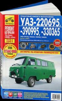
Руководство по эксплуатации, техническому обслуживанию и ремонту автомобилей УАЗ-220695, УАЗ-330365 и УАЗ-390995 с 2008 года выпуска с бензиновым двигателем объемом 2,7 л.
- Автор: —
- Издательство: Третий Рим
- Год издания: —
- Страниц: 304
- Формат: —
- Размер: —
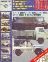
Руководство по техническому обслуживанию и ремонту автомобилей УАЗ-2206/31512/31514/3303/3741/3962/3909/39091 и их модификаций.
- Автор: —
- Издательство: Авто-Книга
- Год издания: 1999
- Страниц: 174
- Формат: DjVu
- Размер: 4,9 Mb
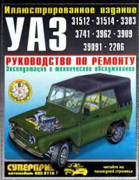
Руководство по эксплуатации, техническому обслуживанию и ремонту автомобилей УАЗ-2206/31512/31514/3153/3303/33036/3741/3909/39094/39095/3962 и их модификаций.
- Автор: —
- Издательство: Третий Рим
- Год издания: 1999
- Страниц: 199
- Формат: DjVu
- Размер: 7,3 Mb
Руководство по эксплуатации и ремонту автомобилей УАЗ-3151, УАЗ-2206 и их модификаций с бензиновыми двигателями объемом 2,5/2,9 л.
- Автор: —
- Издательство: Третий Рим
- Год издания: —
- Страниц: 144
- Формат: —
- Размер: —
Инструкция по эксплуатации автомобилей УАЗ-2206/3303/3741/3909/3962.
- Автор: —
- Издательство: УАЗ
- Год издания: 2003
- Страниц: 113
- Формат: PDF
- Размер: 90,3 Mb
Подборка руководств по эксплуатации автомобилей УАЗ.
- Автор: —
- Издательство: УАЗ
- Год издания: 2007-2012
- Страниц: —
- Формат: PDF
- Размер: 7,2 Mb
Руководство по эксплуатации, техническому обслуживанию и ремонту автомобилей УАЗ-3741, УАЗ-31512 и их модификаций.
- Автор: —
- Издательство: Арго-Авто
- Год издания: —
- Страниц: 220
- Формат: —
- Размер: —
Альбом по устройству и техническому обслуживанию автомобилей УАЗ-2206/31512/31514/3303/33036/3741/3909/39091/3962 и их модификаций.
- Автор: —
- Издательство: УАЗ
- Год издания: 1996
- Страниц: 83
- Формат: PDF
- Размер: 44,9 Mb
Руководство по ремонту электрооборудования автомобилей УАЗ.
- Автор: В.В. Литвиненко
- Издательство: За рулем
- Год издания: 2003
- Страниц: 161
- Формат: DjVu
- Размер: 4,9 Mb

- Manuals
- Brands
- UAZ Manuals
- Automobile
- UAZ-374195
- Operation manual
-
Contents
-
Table of Contents
-
Bookmarks
Quick Links
Ulyanovsk Automobile Plant, PJSC
UAZ-374195, UAZ-396295,
UAZ-220695, UAZ-390995,
UAZ-330365, UAZ-390945
and Versions Thereof
Operation Manual
RE 05808600.106-2007
Vehicles:
9th edition
Ulyanovsk
2016
Related Manuals for UAZ UAZ-374195
Summary of Contents for UAZ UAZ-374195
-
Page 1
Ulyanovsk Automobile Plant, PJSC Vehicles: UAZ-374195, UAZ-396295, UAZ-220695, UAZ-390995, UAZ-330365, UAZ-390945 and Versions Thereof Operation Manual RE 05808600.106-2007 9th edition Ulyanovsk 2016… -
Page 2
A T T E N T I O N ! The manufacturer (UAZ PJSC) cares about its customers and hopes for thoughtful use of its products. While supporting the all-Russian program of road transport accident reduction, the Manufacturer recommends that the maximum speed of 90 km/hr provided in the Traffic Rules for Public Roads not be exceeded. -
Page 3: Chapter 1. General Information
Chapter 1. GENErAl INfOrmATION UAZ-374195 motor vehicle (Fig. 1.1) is a cargo van with an all- metal wagon type closed body separated into a two-seat cab and a cargo compartment. It is designed for hauling cargo. UAZ-374195-05 motor vehicle (Fig. 1.2) is a cargo vehicle with a wagon type body separated into a two-seat cab and a cargo / passenger compartment.
-
Page 14: Motor Vehicle Marking
Manufacturer’s name plate and on roof flute lower plane (on vehicles UAZ-220695, UAZ-220695-04, UAZ-396295 and their versions — in two places: «a» and «b»; on vehicles UAZ-374195, UAZ-374195-05, UAZ-330395, UAZ-330365, UAZ-390995, UAZ-390945 and their versions — in one place: «b»).
-
Page 15
Fig. 1.12. Vehicle marking: 1 — Vehicle identification number: a, b — for UAZ-220695, UAZ-220695-04, and UAZ-396295 vehicles; b — for UAZ-374195, UAZ-374195-05, UAZ-330365, UAZ-330395, UAZ-390945; and UAZ-390995 vehicles; 2 — Chassis identification number; 3 — Body (cab) identification number;… -
Page 25: Chapter 2. Safety Requirements And Warnings
Chapter 2. SAfETY rEQUIrEmENTS AND WArNINGS SAFETY REqUIREMEnTS 1. When operating a motor vehicle, it is necessary to observe road traffic regulations and safety requirements and keep a motor vehicle in good repair, timely carrying out its maintenance and correcting possible malfunctions in order not to injure yourself and others.
-
Page 26
11. Vehicle units heating with open flame is prohibited. 12. Keep the engine clean (engine fouling, especially its crankcase, can cause fire). 13. Make sure that fuel tank’s plugs are closed tightly and there are no leaks from fuel lines. 14. -
Page 27
— the battery must be charged in a well-ventilated room. Electrolyte fume accumulation is dangerous to health and explosion hazardous. 18. Do not wash the vehicle with the engine on. 19. A lifting jack installed improperly can cause serious injury or motor vehicle damage. -
Page 28: Warnings
WARnInGS 1. During the initial operating period all recommendations specified in the chapter «New Vehicle Running-in» shall be strictly observed. 2. Do not drive off with the engine not warmed up. Avoid high engine rpm after cold start. Engine heating at high rpm for faster heat up is forbidden. In order to prevent any difficulties when starting the engine, follow the instructions of the chapter «Engine Start».
-
Page 29
UAZ-220695, UAZ-390995, UAZ-396295, UAZ-390945; and in passenger and cargo compartment of UAZ-374195-05 is not allowed. 20. Transportation of passengers on cargo beds of UAZ-330365, UAZ-330395, and UAZ-390945 is not allowed. 21. UAZ-220695 and UAZ-220695-04 vehicles cannot be used as public or commercial transportation means. -
Page 30: Chapter 3. Controls And Equipment In Driver/Passenger Compartment
4 — multifunctional understeering switches (see Fig. 3.5); 5 — sun visor; 6 — ceiling light. A switch is installed next to the ceiling light; 7 — internal mirror (for UAZ-220695 and UAZ-220695-04); 8 — front handle; 9 — glove box;…
-
Page 31: Transfer Case
0 — a vehicle with a driver only; 1 — passengers on all seats (for UAZ-396295 only); 1 — a vehicle with a driver and maximum permitted cargo load (except for UAZ-396295);…
-
Page 32: 13 — Instrument Cluster
6 — external lights switch; 7 — fuel gauges switch for different tanks (not installed on UAZ- 330365, UAZ-330395, and UAZ-390945); 8 — cover plug;…
-
Page 33
When the indicator switches on, if it is not accompanied by significant deterioration of riding qualities, driving is permitted at low speed to the nearest authorized service station of UAZ PJSC, to carry out diagnostic works. Prolonged operation with the malfunction indicator switched on can lead to malfunction of the engine control system elements. -
Page 34
— battery discharge indicator (red). If it lights up with engine on, it indicates absence of battery charge. — high beam ON indicator (blue). — parking lamps ON indicator (green). — rear fog lights ON indicator (orange). — front fog lights ON indicator (green). —… -
Page 35: Multifunctional Understeering Switches And Ignition Switch
for more than 1 s, minutes displayed are increased faster, initially with a 1 s interval, then with a 0.25 s interval; minutes stop blinking in this case. If the button is not pressed within 5 seconds, the clock switches from the Minutes Correction to the Current Time mode automatically.
-
Page 36
VII (push) — high beam is On, if headlights are switched on by the external lights switch (stable position). 2 — wiper and washer lever with the following positions: I — wiper and washer are OFF; II — windshield intermittent wiper is On (unstable position); III —… -
Page 37: Vehicle Interior And Bodyshell Equipment
It is not possible to lock the doors from the inside. If external handles of front and rear side doors (on all vehicles) and on the rear right door of UAZ-220695 vehicle are locked, the doors can be opened by internal handles.
-
Page 38: Seats
Seats The front seat back inclination angle is adjusted by rotating knob 2 (Fig. 3.6). Some versions of the driver’s seat allow installation in four various longitudinal positions. To change the position: remove the seat, unscrew bolts fixing the seat cushion to the seat frame (reverse side of the seat), shift the seat cushion and screw the bolts in.
-
Page 40: Safety Belts
(Fig. 3.7). Safety belts in UAZ-220695, UAZ-220695-04 , UAZ-396295, UAZ- 390995-04, and UAZ-374195-05 on seats installed towards vehicle travel direction are of diagonally-waist type with retraction devices, and on seats installed against travel direction — of waist type with retraction devices (Fig.
-
Page 41
1 — latch plate; 2 — lock; 3 — lock button Fig. 3.8. UAZ-220695 saloon safety belts: 1 — latch plate; 2 — lock; 3 — lock button keep the belt straps and buckles clean. If they become dirty, clean them it with an alkali-free soap solution. -
Page 42
Fig. 3.9. UAZ-390995-04 saloon safety belts: 1 — latch plate; 2 — lock; 3 — lock button Fig. 3.10. UAZ-390995 and UAZ-390945 saloon safety belts: 1 — latch plate; 2 — lock; 3 — lock button… -
Page 43: Bodyshell (Cab) Ventilation
Replacement of safety belts must be performed only in the authorized service shops of UAZ PJSC (addresses of the authorized service shops are listed in the service book). UAZ PJSC is not responsible for possible injures resulting from, for example, traffic accidents, as well as for any other damage caused by operation rules violation or unauthorized replacement of safety belts.
-
Page 44
heater fan electric motors are turned on and off by switches 10 and 11 (Fig. 3.3). Coolant temperature in the engine cooling system shall be at least 80°С to ensure normal heater operation. Use a winter front supplied with the vehicle in case of low ambient temperatures. -
Page 45: Uaz-396295 Medical Equipment
Guides allowing barrow movement along the bodyshell are installed on the floor to ease barrow handling. Transporting of Patients UAZ-396295 vehicle bodyshell allows transportation of 4 to 6 persons (not including the driver) in the following arrangements: Arrangement with barrows On seats for accompanying persons ….
-
Page 46: Windshield Wiper And Washer
Prepare the vehicle for patients receipt before departure. Carefully check the reliability of barrow suspension units, places of brackets fixation to side panels, their opening and closing, condition of hanging belts stitching and presence of belt loops, attaching points between holders and braces for belts and the ceiling. Install hanging belts (Fig.
-
Page 47: Chapter 4. Vehicle Preparation After Buying
gets clogged, remove it after extracting the clamp and detaching the pipe, and blow it with compressed air. To avoid failure of the washer pumps, check the water level in the reservoir; 20 mm from the bottom is the lowest level permitted. Do not keep washer reservoirs turned On for more than 10 sec.
-
Page 48: Chapter 6. Engine Start And Stop
Chapter 6. ENGINE STArT AND STOP GEnERAl PROVISIOnS Before starting the engine, check for the coolant in the engine cooling system, fuel, and oil level in the engine crankcase. move the gearshift lever in a neutral position. Release the ignition key immediately after the engine starts. The key returns to position I automatically (Fig.
-
Page 49: Engine Stop
Before shutting down the engine, let it run for 1-2 minutes at low rpm. Chapter 7. VEHIClE DrIVING IN DIffErENT rOAD, WEATHEr AND ClImATIC CONDITIONS The manufacturer (UAZ PJsC) cares about its customers and hopes for thoughtful use of its products. While supporting the all-Russian program of road transport accident reduction, the Manufacturer recommends that the maximum speed of 90 km/hr provided in the Traffic Rules for Public Roads not be exceeded.
-
Page 50
with high average speed and low fuel consumption over difficult road sections. We recommend to start off at level stretches of hard-surface roads or downward in the second gear. In all other cases, start the motion in the first gear. Change gears and engage the front axle when the clutch is disengaged: — disengage the clutch fast by pressing the clutch pedal as far as it can go;… -
Page 51
also the speed reduction gear in the transfer case. Engage the front axle while the motor vehicle is moving, and engage the speed reduction gear in the transfer case after a complete stop of the vehicle only. Overcoming steep inclines and declines. When driving on roads with steep inclines and declines, a driver shall be very careful and have quick reflexes. -
Page 52
difficult to steer the vehicle on extremely wet graded roads with steep grades and deep trenches. On these roads, drive carefully on the crest of the corrugation and at low speed. Overcome marsh-ridden sections by driving along the straight line without sharp turns and stops. -
Page 53: Chapter 8. Vehicle Towing
The vehicle can move along virgin snow of 350 mm in depth. Steer the vehicle in the same manner, as when moving on swampy grounds. When driving on friable snow, apply the same rules, as when driving on sand surfaces. Chapter 8.
-
Page 54: Vehicle Maintenance Every 500 Km
2. Check functioning of the steering system, brake systems, illumination devices, light and sound alarm, windscreen wiper. Eliminate any revealed defects. 3. Fill the windshield washer tank. Water is allowed for use in warm season. 4. If the vehicle was operated in extremely dusty conditions or crossed fords and country road sections covered with liquid mud, check the condition of a filter element of the engine air filter and replace it, if necessary.
-
Page 55
4. Wash fuel tanks prior to the winter season of operation (or after 30,000 km). 5. Check braking system efficiency and proportioning valve operability. 6. Switch the windshield wiper for 15 — 20 minutes with blades away from the glass. 7. -
Page 56: Engine
EnGInE Engine Suspension In operation, check tightening of threaded joints of the front and rear engine suspensions (see Appendix 2) and condition of the struts. no delamination or breakage of the engine struts is allowed. Engine Cylinder Head Cylinder head bolts tightening is not required during operation. Perform the tightening only when the engine is cold, if necessary.
-
Page 57
(when the first 2,500 km are covered) with one of the following filters: 2101С-1012005-NK-2, 2105С-1012005-NK-2 manufactured by KOLAN, or 409.1012005 manufactured by BIG-Filter, LLC. For oil cooling, the lubrication system comprises the oil cooler connecting into the cooling process automatically using the thermal valve. Regularly check the oil level in the housing and fill it up, as required. -
Page 58: Engine Housing Ventilation System
Fig. 9.2. Engine ZMZ-40911 (left side view): 1 — coolant from radiator to water pump supply pipe; 2 — connection hoses; 3 — control unit coolant temperature sensor; 4 — thermostat housing; 5 — coolant branch pipe from thermostat to radiator; 6 — critically low oil pressure sensor; 7 — ignition coils; 8 —…
-
Page 59: Engine Cooling System
Fig. 9.3. Engine ZMZ-40911 (right side view): 1- coolant to heater branch pipe; 2 — heater coolant discharge tube; 3 — pinking sensor; 4 — proportioning valve; 5 — fuel rail with nozzles; 6 — absolute pressure sensor; 7 — upper hydraulic tensioner cap; 8 — engine elevation front bracket; 9 — lower hydraulic tensioner cap;…
-
Page 60
CRANKCASE GASES AND CLEAN CLEAN AIR MIXTURE Fig. 9.4. Engine housing ventilation diagram: 1 — main ventilation circuit; 2 — receiver 3 — short ventilation circuit; 4 — valve cap; 5 — oil baffle; 6 — crankcase gases deflector; 7 — inlet pipe; 8 — throttle pipe TOSOl-A40M, OZh-40 lena or OZh-40 TOSOl-TS low-freezing fluids are used as coolants. -
Page 61: Exhaust System
Tighten bolts 13. fan drive clutch. In case the clutch does not switch on and off properly, the engine can overheat. Check up to be done at a specialized UAZ workshop. keep the clutch surface clean. Exhaust System ATTENTION! The catalyst operating temperature is between 400- 800°С.
-
Page 62
Fig. 9.5. Aggregates drive belt tension 1 — crankshaft damping pulley; 2 — tensioning roll; 3 — tensioning roll fixing bolt; 4 — adjusting bolt; 5 — water pump and alternator driving belt; 6 — alternator; 7 — inlet pipe; 8 —… -
Page 63
Fig. 9.6. Principal diagram: fuel and engine control system (with gasoline injection) 1 — left (main) tank; 2 — fuel tank plugs; 3 — jet pump; 4 — electric fuel pump (submersible module); 5 — fuel tank valve; 6 —separator 7 — absorber; 8 — right (additional) tank; 9 —… -
Page 64: Gasoline Injection System With Microprocessor-Controlled Fuel Feed And Ignition
Gasoline Injection System with microprocessor- Controlled Fuel Feed and Ignition (Fig. 9.6) Precautions 1. Before disassembling and assembling any parts or cables of the steering system disconnect a mass wire from the battery. 2. DO nOT start the engine without a safe battery and ground wire connection between the engine and the bodyshell.
-
Page 65: Fuel System
10. The fuel pump electric motor is cooled by the passing fuel flow; thus, DO nOT turn the electric fuel pump on ‘dry’, when the left fuel tank is empty, to avoid its damage. 11. Do not start the engine with incorrectly installed high-voltage wires between ignition coils and spark plugs, and low-voltage wires to ignition coils.
-
Page 66
To be flushed, the fuel tanks shall be dismantled from the motor vehicle. Electric fuel pump. Regularly check and clean fuel pump pins and connections to the onboard power supply. Pay special attention to reliability of the ground connection. It is not recommended to operate the motor vehicle if there is less than 5 liters of fuel in the left fuel tank. -
Page 67
5. Check the right fuel tank connection to the atmosphere. The drain line from the engine (proportioning valve) into the left tank shall not be squeezed. 6. Measure the fuel flow at the fuel rail drain (it shall be at least 75 l/h at the back pressure of 300-10 kPa and the power supply voltage of (13.5 ±… -
Page 68: Evaporative Emission Control System
Air filter. The filter element shall be replaced after each 15,000 km of travel, as well as in case of engine power decreasing (e.g., if operated in very dusty environment). The filter element shall be replaced as follows: — loosen clamps and remove corrugated hoses from the air filter; — unscrew clamp nuts, remove the clamp and the air filter;…
-
Page 69: Fuel Supply And Ignition Control System
of joints and separator, state of the absorber (absence of cracks and damages, serviceability of the absorber purge valve); — operability of the evaporative emission control system (including the absorber and the fuel tank valve). Any failure of these elements leads to fuel supply system failures.
-
Page 70
In case of faults caused by ignition failures (the engine malfunction lamp starts flashing), to avoid the exhaust converter failure it is necessary to reduce the engine crankshaft rotation speed down to 2,500 rpm (the motor vehicle speed shall not exceed 50 km/h) and to drive to a service station. -
Page 71: Transmission
TRAnSMISSIOn Clutch The fluid level shall be 15-20 mm lower than the upper edge of the tank. Pedal softness and incomplete clutch release indicate air presence in the hydraulic drive. Bleed the system via bleed fitting 9 (Fig. 9.11) of the working cylinder similarly to the bleeding of the brake hydraulic drive.
-
Page 72: Gearbox And Transfer Case
Gearbox and Transfer Case When a leak is detected, find out the reason and defected parts (gaskets, cuffs), replace them, cover the thread of the hollow bolts and socket surfaces with a sealant gasket. Check the grease level and change it in the gearbox and in the transfer case simultaneously.
-
Page 73: Driving Axles
Fig. 9.15. Rear Propeller Shaft: 1 — lubrication nipple for spline coupling; 2 — lubrication nipple for joint needle bearings Driving Axles Drain oil through orifice 2 (Fig. 9.16, 9.17) at the bottom of the housing by unscrewing inspection hole plug 1. Axial clearance of more than 0.05 mm in the bearings of the axle drive pinion is not allowed, as greater clearance will lead to premature pinions teeth wear and the axle jam.
-
Page 74
Fig. 9.16. Front Axle with Vertically Split housing: 1 — gauge plug; 2 — drain plug; 3 — safety valve Fig. 9.17. Front Axle With Banjo housing: 1 — filler orifice plug; 2 — drain orifice plug; 3 — safety valve… -
Page 75
If the critical parameter is not reached, tighten the clamping bush once again by turning the wrench by 10-20° and tighten nut 13 with the specified torque. If air gaps cannot be removed after the tightening of the threaded bush, pins assemblies liners shall be replaced. Contact UAZ service station. -
Page 76: Chassis
Fig. 9.19. Steering knuckle and Wheel hub: 1 — steering knuckle housing; 2 — pin; 3 — pin liner; 4 — spring; 5 — outer O-ring; 6 — inner O-ring; 7 — joint; 8 — ball strut; 9 — outer oil seal housing; 10 — clamping bush;…
-
Page 77: Wheels And Tires
main reason of springs malfunction, and to eliminate spring creaks. To lubricate the spring remove it from the vehicle, dismantle, wash in kerosene, dry and lubricate each leaf thoroughly with the grease, specified in the grease table. Small-leaf springs can be greased only on surfaces of the spring ends, between the clamps and on side surfaces of the leaves.
-
Page 80
Check and adjust the toe-in of the wheels on a special stand. If no stand is available, check and adjust the toe-in of the wheels by the inner surface of tires as follows. Adjust the toe-in of the wheels with the normal tire pressure, so that dimension A (Fig. -
Page 81: Wheel Hubs
Fig. 9.24. Spare Wheel Attachment: A — for UAZ-374195, UAZ-396295, UAZ-390995, UAZ-220695, UAZ-330365, UAZ-390945; B — for UAZ-330395; 1 — spare wheel; 2 — sector; 3 — holder; 4 — nut; 5 — bolt; 6 — washer; 7 — bracket…
-
Page 82
Fig. 9.25. Rear Wheel hub: 1 — wheel; 2 — hub bolt; 3 — wheel nut; 4 — adjusting nut; 5 — axle shaft bolt; 6 — lock washer; 7 — locknut; 8 — thrust washer; 9 — axle shaft; 10 — stub axle; 11 —… -
Page 83
When replacing the bearings, tighten the nut with the torque of 35–40 N · m (3.5–4.0 kgf · m) and the locknut with the torque of 25–30 N · m (2.5–3.0 kgf · m). Install the lock washer with its inner tab into the stub axle slot. If the lock washer tabs have any cracks, replace the washer. -
Page 84: Control Systems
COnTROl SYSTEMS Steering System ATTENTION! The disabled hydraulic power steering increases the effort, necessary for turning the steering wheel. It is not allowed to turn off the IGN and remove the key from the IGN switch while the vehicle is moving. (The steering system shaft is blocked by the anti-theft device when the key is removed, and the vehicle gets uncontrolled).
-
Page 85
If air gaps in the steering mechanism are detected, adjust the mechanism at UAZ service station. Hydraulic Power Steering. When turning the steering wheels to the right or to the left up to the stop the noise in the hydraulic power steering may occur as a result of the maximum pressure in the hydraulic pump. -
Page 86
Fig. 9.26. Under hood Space: 1 — radiator of engine cooling system; 2 — engine; 3 — oil tank of hydraulic power steering system Note. If the oil foams abundantly in the tank, which means that air has entered into the system, stop the engine and let the oil settle for no less than 20 min (until bubbles come out from the oil). -
Page 87: Brake Systems
2. Remove spring 5 and control valve spool 1, put the dummy plug into its place, which will prevent oil outflow. 3. Unscrew safety valve seat 6, remove ball 4, guide 3 and spring 2. Remove ring 8 and filter 7 from the safety valve seat. 4.
-
Page 88
— take off the clothes covered in the fluid, dry them outside the room and wash. Service brake system: disc brakes on front wheels; drum brakes on rear wheels; two separate circuits with the hydraulic drive, coming from the twin-barrel master cylinder: the one barrel to the front wheel brakes, the other barrel to the rear wheel brakes. -
Page 89
IGn) indicates the system malfunction. Despite the fact that it does not affect the work of the brake hydraulic drive, it is recommended to contact UAZ service station to eliminate the malfunction. Illumination of the red brake system warning light (except for self test mode when cycling the IGn) indicates critical malfunction (electronic brakeforce distribution (EBD) malfunction, system leakage, etc.). -
Page 90
Check the brake disc. If its surface has deep notches and burrs, remove it, clean and grind. When the disc wears to the thickness of 20.4 mm, replace it. Check safety caps 5 and boots 8 for damages and proper installation in seats, replace them, if necessary. -
Page 91
Fig. 9.29. Rear Wheel Brake: a — anchor stud marks; 1 — anchor studs; 2 — shield; 3 — orifices for visual inspection of brake linings; 4 — wheel brake cylinder; 5 — bypass valve; 6,12 — brake shoes; 7 — safety cap; 8 — piston; 9 —… -
Page 92
After reassembly push the brake pedal 2-3 times to install the pistons into the working position. Do not press the brake pedal when the brake drum or the front brake shoes are removed, as the compressed fluid will press the pistons out of the wheel cylinders and the fluid will escape. -
Page 93
no stroke, as well as poor or excessive stroke, the valve or its drive has malfunctions. When inspecting the hydraulic drive pay attention to protective boot 1, to the position of gauge plug 15 and to brake fluid leaks from it. The plug shall normally be sunk into the housing orifice of the valve. -
Page 94
View A Fig. 9.32. Drive of Master Brake Cylinder: 1 and 18 — brackets; 2 — brake signal switch; 3 — nuts; 4 — buffer-stop; 5 — brake pedal; 6 — intermediate yoke; 7 — yoke; 8 — locknut; 9 — rod; 10 — boot; 11 — intermediate lever;… -
Page 95
If air comes into the brake system of the ABS-equipped vehicle, contact a service station. It is forbidden to operate the vehicle until the malfunction is eliminated. 1. Bleed successively the chambers of the right and left rear brakes wheel cylinders, the front circuit of the proportioning valve (for non-ABS vehicles), and then the right and the left front brakes wheel cylinders. -
Page 97
Clean the brake shoes of dust and dirt and sand them if they get greasy. Replace greasy linings or keep them in gasoline for 20-30 minutes and grind them with sand paper or wire brush. Replace the linings and the shoes in case of the linings excessive wear (the rivets are sunk less than 0.5 mm). -
Page 98
Adjust the cable length (when replacing the cable) as follows: 1. Move brake lever 1 into its extreme front position. 2. Unscrew the locknuts of adjusting yoke 7, remove the snap pin and take out the stud, which connects the yoke with brake drive lever. 3. -
Page 99: Electric Equipment
ElECTRIC EqUIPMEnT relay and fuse Box The relay / fuse box is located on the right from the passenger under the instrument panel, next to the bodyshell front rack (Fig. 9.35). The scheme of relays and fuses is shown on the inner side of the box cap (Fig.
-
Page 100: Alternator
Do not use metallic objects while removing a relay or a fuse. While operating the vehicle and checking the electric equipment scheme do not use non-UAZ certified fuses (see Table 9.1) and do not loosen the wires on the ground wire (to check the work of the chain).
-
Page 101: Battery
Battery The battery is installed in the cab on the left, behind the wheel arch. UAZ-220695 and UAZ-396295 vehicles have a ventilation tube on the battery. Tube 2 (Fig. 9.37) goes outside the cab under the hood. Check the alternator if the battery is discharged, overcharged by the alternator or electrolyte starts boiling.
-
Page 102
Fig. 9.37. Battery of UAZ-220695, UAZ-396295: 1 — hood; 2 — ventilation tube; 3 — plus terminal; 4 — adapter; 5 — battery; 6 — minus terminal — check the relay switch outputs and the working surface of electric terminals;… -
Page 103: Lighting System, Light And Audio Alarm
lighting System, light and Audio Alarm Despite the good sealing, dust may penetrate into the beam unit. Without dismantling the beam unit wash it with clean water through the unit orifice, and then dry the unit. To replace a bulb in the lamp, untwist screw 1 (Fig.
-
Page 104: Gages And Alarms
Fig. 9.39. Screen marking for headlamps adjustment: h — distance between headlamps center and ground level Fig. 9.40. Screen marking for front fog lights adjustment: h — distance between lights center and ground level; l — distance between front fog lights centers front and rear lamps, backing lamp, side repeaters, rear fog lamp.
-
Page 105: Bodyshell
When removing electric sensors isolate the wires to avoid short circuit. Use a hex socket wrench or a box wrench to remove the coolant temperature sensor and the coolant emergency temperature sensor without damaging their housings. Check the fluid level in the cooling system radiator; if the fluid level is low, the sensor may come out of order.
-
Page 106: Vehicle Lubrication
VEhIClE lUBRICATIOn It is strongly recommended to follow the instructions hereof and the lubrication Service Manual. The grease names are indicated in the lubricants and Fluids Table (see Appendix 3). It is not allowed to use oils and greases, which are not indicated in the table, and to break greasing intervals.
-
Page 107
Fig. 10.1. Jack: 1 — housing; 2 — external screw; 3 — internal screw; 4 — head; 5 — pawl; 6 — handle; 7 — ratchet 1. Apply the parking brake, shift into the first or the reverse gear of the gearbox and make sure that the transfer case lever is not in the neutral position. -
Page 108: Chapter 11. Preservation
Chapter 11. PrESErVATION If the vehicle is not operated for a long time, preserve it as follows: 1. Carry out the scheduled maintenance. 2. Wash the vehicle and wipe it dry. Remove corrosion and paint areas of damaged paint. 3. Fill each engine cylinder with 30-50 g of hot dehydrated motor oil to prevent them from corrosion.
-
Page 109: Preserved Vehicle Maintenance
Release the rear and front springs by putting wooden spacers between the frame and the axles. keep the preserved vehicle in a clean and ventilated room with the relative humidity of 40-70 % and at temperature of +5°С at least. Do not keep the vehicle and poisonous substances (acids, alkali etc) in the same room.
-
Page 110: Chapter 12. Transportation
Chapter 12. TrANSPOrTATION Vehicles can be transported by railway, water or air transport. When transporting vehicles by water or air transport fasten them in accordance with the water transport shipment scheme or the air transport shipment scheme. Use appliances, which will not damage any parts or painted surfaces.
-
Page 111: Appendix 1. Vehicle Lamps
Appendix 1 VEHIClE lAmPS lamps lamp Type Power, W lamps: high beam and low beam AKG12-60+55-1(N4) 60х55 headlamps: Parking lamps А12-5 Turn indicators А12-21-3 Rear lamps: Turn indicators А12-21-3 Parking lamps А-12-5 Brake indicators А-12-21-3 Turn repeaters А12-5 Reverse lamp А12-21-3 license plate lamp А12-5…
-
Page 112: Appendix 2. Tightening Torque Of Main Threaded Couplings
Appendix 2 TIGHTENING TOrQUE Of mAIN THrEADED CoUPLINGs, kGF•M Bolts of crankcase cylinder head (soft gasket of cylinder head) pretension 6.9–8.2 holding min. 2 minutes 70-75° angle tightening Bolts of crankcase cylinder head (rigid gasket of cylinder head) pretension 3.3–3.7 holding min.
-
Page 113
Appendix 2 (continued) Clamps of cooling system hoses 0.4–0.45 Clamps of heating system hoses 0.25–0.35 Cooling system radiator bolts 3.2–3.6 Bolts of idle governor clamp 0.6–0.9 Detonation sensor nut 1.5–2.0 Sensors bolts (camshaft position sensor, crankshaft position sensor) 0.6–0.9 Bolts of timing sensor, absolute pressure sensor and temperature sensor 0.6–0.9 Cooling system temperature sensor 1.2–1.8… -
Page 117: Appendix 4. Information On Precious Metals In Vehicle Electric Equipment
Appendix 4 INfOrmATION on Precious Metals in vehicle Electric Equipment Manufacturing Item name Precious Metal Weight, g Type 6232.3827 Fuel level sensor (for ve- silver 0.013238 hicles with two fuel tanks) palladium 0.0046744 ruthenium 0.00064147 6002.3829 Oil emergency pressure sensor silver 0.0310 101.3839…
-
Page 118: Table Of Contents
Seats ……………………38 Safety Belts ………………….40 Bodyshell (Cab) Ventilation …………….43 Bodyshell (Cab) heating ………………43 UAZ-396295 Medical Equipment …………..45 Windshield Wiper and Washer …………….46 Chapter 4. Vehicle Preparation After Buying…………..47 Chapter 5. new Vehicle Running-in …………….47 Chapter 6. Engine Start and Stop ……………….48 General Provisions ………………..48…
-
Page 119
Clutch……………………71 Gearbox and Transfer Case……………..72 Drive-line ………………….72 Driving Axles ………………….73 Chassis ……………………76 Suspension ………………….76 Wheels and Tires ………………..77 Wheel hubs ………………….81 Control Systems …………………..84 Steering System ………………..84 Brake Systems ………………..87 Electric Equipment ………………..99 Relay and Fuse Box ………………..99 Alternator ………………….100 Battery ………………….101 Starter Motor…………………101 lighting System, light and Audio Alarm …………103… -
Page 120
Vehicles: UAZ-374195, UAZ-396295, UAZ-390995, UAZ-220695, UAZ-330365, UAZ-390945 and Versions Thereof Operation Manual RE 05808600.106-2007 9th Edition Prepared for publishing by UAZ Chief Designer Department Editor-in-Chief Chief Designer O.A. kRUPIn Editor I.l. nIkOlAEV Content by D.A. ShEMYREV…
9,49 Мб
Автомобили УАЗ-451М, УАЗ-451ДМ, УАЗ-452А, УАЗ-452В,
Формат: djvu
-
Год:
1973
-
Страниц:
321
-
Язык:
русский
-
Размер:
9,49 Мб
-
Категории:
УАЗ-452 «Буханка»
2,76 Мб
Автомобили УАЗ-469, УАЗ-452Д, ГАЗ-52-04, ГАЗ-53А, ГАЗ-66,
Формат: djvu
-
Год:
1983
-
Страниц:
192
-
Язык:
русский
-
Размер:
2,76 Мб
-
Категории:
УАЗ-452 «Буханка»
4,92 Мб
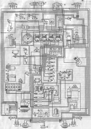
Электросхемы автомобилей УАЗ-452, УАЗ-469, УАЗ-31512,
Формат: djvu
-
Год:
2003
-
Страниц:
161
-
Язык:
русский
-
Размер:
4,92 Мб
-
Категории:
УАЗ-452 «Буханка»
92,7 Мб
Руководство по эксплуатации автомобилей УАЗ-3741, УАЗ-3962,
Формат: pdf
-
Год:
2003
-
Страниц:
225
-
Язык:
русский, английский
-
Размер:
92,7 Мб
-
Категории:
УАЗ-452 «Буханка»
3,89 Мб
Автомобили УАЗ-451М и УАЗ-452 «Буханка»: Устройство,
Формат: djvu
-
Год:
1969
-
Страниц:
149
-
Язык:
русский
-
Размер:
3,89 Мб
-
Категории:
УАЗ-452 «Буханка»
4,88 Мб
Автомобили УАЗ-3151, УАЗ-3741, УАЗ-3962, УАЗ-2206,
Формат: djvu
-
Год:
1999
-
Страниц:
174
-
Язык:
русский
-
Размер:
4,88 Мб
-
Категории:
УАЗ-452 «Буханка»
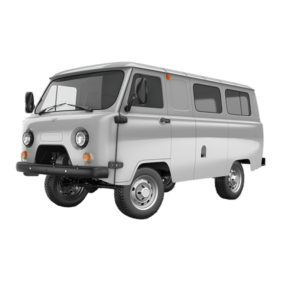
УАЗ-31512/ УАЗ-31514/ УАЗ-3153 удлинённая база, УАЗ-3741 «Буханка» и модификации: УАЗ-3962 «Санитарный»/ УАЗ-2206 «Микроавтобус»/ УАЗ-3303 «Грузовая платформа»/ УАЗ-3909 «Фермер»/ УАЗ-33036/ УАЗ-39094/ УАЗ-39095 с бензиновыми двигателями: УМЗ-4178.10 2.5 л (2445 см³) 76 л.с./55.9 кВт и УМЗ-4218.10 2.9 л (2890 см³) 84 л.с./61.8 кВт; Руководство по эксплуатации, техническому обслуживанию и ремонту. Советы по выбору запасных частей, особенности эксплуатации и ремонта, устранения неисправностей в пути, цветные электросхемы, диагностика, особенности конструкции, технические характеристики. Иллюстрированное издание легковой автомобиль повышенной проходимости J-класса UAZ микроавтобусы 8-11 местные, бортовые грузовые и грузопассажирские, рамный внедорожник с цельнометаллическими и со съёмным мягким верхом кузовами пятидверный универсал полноприводные модели первого поколения выпуска с 1985 года
ЕСЛИ ВЫ ВИДИТЕ ОШИБКУ 406 Not Acceptable и не видите документ, то скорей всего у Вас IP РФ и его надо сменить, на любой другой страны, с помощью VPN ( Scribd и SlideShare блокируют посетителей с Российским IP).
Видео УАЗ-31512/-3741/-3303/-2206/-3909 замена МКПП и наружных дверных ручек (UAZ с 85)
УАЗ-31512, УАЗ-3741, УАЗ-3303, УАЗ-2206, УАЗ-3909 общая информация (UAZ с 1985)
Снятие коробки передач с автомобилей семейства УАЗ-3741
Снятие проводите в следующем порядке:
1. Слейте масло из коробки передач и раздаточной коробки.
2. Снимите вилку выключения сцепления.
3. Снимите колпачковую масленку подшипника выключения сцепления и отсоедините ее от шланга смазки подшипника.
4. Отсоедините тяги переключения передач от механизма переключения передач и раздаточной коробки.
5. Поддержите двигатель снизу с помощью домкрата или другого устройства.
6. Отверните и разберите задние опоры подвески двигателя.
7. Отсоедините фланцы карданных валов.
8. Отсоедините трос привода стояночного тормозного механизма.
9. Отсоедините гибкий вал спидометра.
10. Отверните четыре гайки крепления коробки передач к картеру сцепления.
11. Отведите агрегат назад до выхода первичного вала то картера сцепления.
12. Опустите агрегат вниз.
Установку агрегата на автомобиль производите в обратном порядке.
Отсоединение коробки передач от раздаточной коробки
1. Установите агрегат вертикально на барабан стояночного тормозного механизма.
2. Включите в раздаточной корейке прямую передачу.
3. Отверните три гайки шпилек и два болта крепления коробки передач к раздаточной коробке.
4. Поднимая коробку передач вверх, отсоедините ее от раздаточной коробки.
5. После снятия коробки передач на раздаточной коробке остается прокладка, пластина подвески, вторая прокладка и упорное кольцо подшипника промежуточного вала коробки передач.
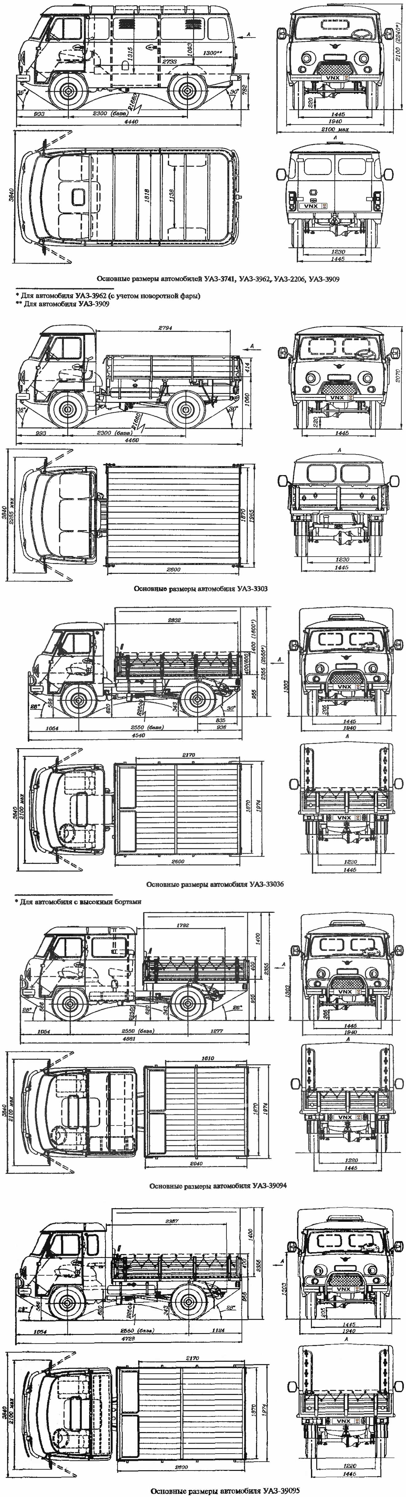
| № | Спецификация / Specs | Данные |
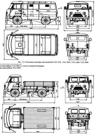
| Габариты (мм/mm) и масса (кг/kg) / Dimensions and Weight | ||
| 1 | Длина / Length | 4440 |
| 2 | Ширина (без/с зеркалами) / Width | 1940/2100 |
| 3 | Высота (загружен/пустой) / Height | 2100 |
| 4 | Колёсная база / Wheelbase | 2300 |
| 5 | Дорожный просвет (клиренс) / Ground clearance | 220 |
| 6 | Снаряжённая масса / Total (curb) weight | 1720 |
| Полная масса / Gross (max.) weight | 2720 | |
|
Двигатель / Engine |
||
| 7 | Тип / Engine Type, Code | Бензиновый, жидкостного охлаждения, четырехтактный, УМЗ-4178.10 |
| 8 | Количество цилиндров / Cylinder arrangement: Total number of cylinders, of valves | 4-цилиндровый, рядный, 8V, OHV с нижним расположением одного распределительного вала |
| 9 | Диаметр цилиндра / Bore | 92.0 мм |
| 10 | Ход поршня / Stroke | 92.0 мм |
| 11 | Объём / Engine displacement | 2445 см³ |
| 12 | Система питания / Fuel supply, Aspiration | Карбюратор К-151В |
| Атмосферный | ||
| 13 | Степень сжатия / Compression ratio | 7.0:1 |
| 14 | Максимальная мощность / Max. output power kW (HP) at rpm | 55.9 кВт (76 л.с.) при 4000 об/мин |
| 15 | Максимальный крутящий момент / Max. torque N·m at rpm | 159.8 Нм при 2200-2500 об/мин |
|
Трансмиссия / Transmission |
||
| 16 | Сцепление / Clutch type | Однодисковое, сухое, с диафрагменной нажимной пружиной и гасителем крутильных колебаний, постоянно замкнутого типа |
| 17 | КПП / Transmission type | МКПП 4 четырёхступенчатая механическая, двухвальная, с синхронизаторами на всех передачах переднего хода, с двухступенчатой раздаткой и блокировкой межосевого дифференциала |
О Книге
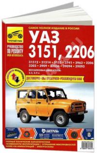
- Название: Автомобили УАЗ-31512, УАЗ-31514, УАЗ-3153, УАЗ-3741, УАЗ-3962, УАЗ-2206, УАЗ-3303, УАЗ-3909, УАЗ-33036, УАЗ-3909, УАЗ-39094, УАЗ-39095 и их модификации/ Руководство по ремонту и техническому обслуживанию
- Бензиновые двигатели: УМЗ-4178.10 2.5 л (2445 см³) 76 л.с./55.9 кВт и УМЗ-4218.10 2.9 л (2890 см³) 84 л.с./61.8 кВт
- Выпуск с 1985 года
- Серия: «Ремонт без проблем»
- Год издания: 1999
- Автор: Коллектив авторов
- Издательство: «Ассоциация независимых издателей»
- Формат: PDF
- Страниц в книге: 199
- Размер: 81.3 МБ
- Язык: Русский
- Количество электросхем: более 20

Поддержка и продвижение сайта — Avada.ru
Обращаем Ваше внимание на то, что вся представленная на сайте информация, носит информационный характер и ни при каких условиях не является публичной офертой, определяемой положениями Статьи 437 (2) Гражданского кодекса Российской Федерации. Наличие конкретных комплектаций, опций и оборудования по доступным автомобилям уточняйте у продавцов консультантов.
Предоставляя свои персональные данные и используя настоящий веб-сайт, Вы даете согласие на обработку Ваших персональных данных и принимаете условия их обработки. Политика конфиденциальности.
Для повышения удобства работы с сайтом и обеспечения его корректной работы компания АвтоГЕРМЕС использует файлы cookie. Эти файлы содержат данные о предыдущих посещениях Вами сайта. Cookie не идентифицируют Ваши личные данные. Вся информация является сугубо конфиденциальной. При необходимости Вы можете отключить cookie с помощью настроек браузера.