- Manuals
- Brands
- Suzuki Manuals
- Motorcycle
- GSX600F
Manuals and User Guides for Suzuki GSX600F. We have 1 Suzuki GSX600F manual available for free PDF download: Service Manual

Suzuki GSX600F Service Manual (374 pages)
Brand: Suzuki
|
Category: Motorcycle
|
Size: 131.36 MB
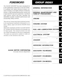
Table of Contents
-
Group Index
3
-
Symbol
4
-
Component Parts and Work to be Done
5
-
General Information
6
-
Warning/Caution/Note
7
-
General Precautions
7
-
Suzuki GSX600FW (’98 Model) Right Side
9
-
Suzuki GSX600FW (’98 Model) Left Side
9
-
Serial Number Location
9
-
Fuel and Oil Recommendation
9
-
Engine Oil
10
-
Brake Fluid
10
-
Front Fork Oil
10
-
Break-In Procedures
10
-
Cylinder Identification
11
-
Information Labels
12
-
Specifications
13
-
Country and Area Codes
15
-
Periodic Maintenance
16
-
Periodic Maintenance Schedule
17
-
Periodic Maintenance Chart
17
-
Lubrication Points
18
-
Maintenance and Tune-Up Procedures
19
-
Valve Clearance
19
-
Spark Plugs
20
-
Carbon Deposits
21
-
Spark Plug Gap
21
-
Electrode’s Condition
21
-
Spark Plug Installation
21
-
Exhaust Pipe Bolts and Muffler Bolts and Nut
22
-
Air Cleaner
22
-
Engine Oil Replacement
24
-
Fuel Hose
25
-
Engine Oil Filter Replacement
25
-
Necessary Amount of Engine Oil
25
-
Fuel Filter
26
-
Engine Idle Speed
26
-
Throttle Cable Play
26
-
Carburetor Synchronization
27
-
Evaporative Emission Control System (E-33 Only)
27
-
Secondary Air Supply (Pair) System (E-33 Only)
28
-
Clutch Cable Play
28
-
Drive Chain
29
-
Drive Chain Adjusting
30
-
Drive Chain Cleaning and Lubricating
30
-
Brake Fluid Level
31
-
Brake Pads
32
-
Brake Pedal Height
32
-
Brake Light Switch
33
-
Air Bleeding the Brake Fluid Circuit
33
-
Tire Tread Condition
35
-
Tire Pressure
35
-
Steering
36
-
Front Fork
36
-
Rear Suspension
36
-
Chassis Bolts and Nuts
37
-
Compression Pressure Check
39
-
Compression Test Procedure
39
-
Oil Pressure Check
40
-
Oil Pressure Test Procedure
40
-
Low Oil Pressure
40
-
High Oil Pressure
40
-
Engine
41
-
Engine Components Removable with Engine in Place
42
-
Engine Removal
43
-
Engine Installation
47
-
Engine Disassembly
51
-
Engine Reassembly
65
-
Cylinder Block Stud Bolt Location
77
-
Camshaft/Cylinder Head
88
-
Camshaft Removal
89
-
Cylinder Head Removal
90
-
Camshaft/Cylinder Head Inspection and Service
92
-
Cam Wear
93
-
Camshaft Journal Wear
93
-
Camshaft Runout
94
-
Camshaft Sprockets
94
-
Cam Chain Tensioner
95
-
Cam Chain Guide
95
-
Cam Chain Tensioner Guide
95
-
Cylinder Head Disassembly
95
-
Cylinder Head Distortion
97
-
Valve Stem Runout
97
-
Valve Head Radial Runout
97
-
Valve Face Wear
98
-
Valve Stem Deflection
98
-
Valve Stem Wear
98
-
Valve Guide Servicing
99
-
Valve Seat Width
100
-
Valve Seat Servicing
100
-
Valve Stem End Condition
102
-
Valve Springs
102
-
Cylinder Head Reassembly
103
-
Intake Pipes
104
-
Cylinder Head Installation
105
-
Camshaft Installation
108
-
Cylinder Block/Pistons
110
-
Cylinder Block/Piston Removal
111
-
Cylinder Block/Piston Inspection
112
-
Cylinder Block Distortion
112
-
Cylinder Bore
112
-
Piston Diameter
112
-
Piston-To-Cylinder Clearance
113
-
Piston-Ring-To-Groove Clearance
113
-
Piston/Cylinder Block Installation
114
-
Piston Pins and Pin Bore
114
-
Oversize Piston Ring
114
-
Oversize Oil Ring
114
-
Piston/Cylinder Block
116
-
Clutch
117
-
Clutch Removal
118
-
Clutch Release Assembly Removal
120
-
Clutch/Clutch Release Assembly Inspection
120
-
Clutch Drive Plates
120
-
Clutch Driven Plates
121
-
Clutch Spring Free Length
121
-
Clutch Release Bearing
121
-
Clutch Release Assembly Installation
122
-
Clutch Installation
123
-
Starter System/Signal Generator
125
-
Starter Clutch Removal
126
-
Signal Generator Removal
127
-
Starter Clutch/Signal Generator Inspection
127
-
Signal Generator Installation
128
-
Starter Driven Gear Bearing Inspection
128
-
Signal Generator Inspection
128
-
Starter Clutch Installation
129
-
Starter Motor Removal
130
-
Starter Motor Inspection
130
-
Starter Motor Installation
130
-
Gearshift Linkage
131
-
Gearshift Linkage Removal
132
-
Gearshift Linkage Inspection
133
-
Gearshift Shaft/Gearshift Arm Inspection
133
-
Oil Seal Inspection
133
-
Oil Seal Replacement
133
-
Gearshift Shaft Hole Inspection
134
-
Gearshift Shaft Reassembly
134
-
Gearshift Linkage Installation
135
-
Crankcase/Transmission/Crankshaft/Conrods
137
-
Transmission/Crankshaft/Conrod Removal
139
-
Transmission Inspection and Service
139
-
Gearshift-Fork-To-Gearshift-Fork-Groove Clearance
139
-
Countershaft Assembly
140
-
Driveshaft Assembly
141
-
Conrod/Crankshaft Inspection
146
-
Conrod-Crank Pin Bearing Inspection and Service
146
-
Conrod Small End I.D.
146
-
Conrod Big End Side Clearance
146
-
Conrod-Crank Pin Bearing Selection
147
-
Bearing Selection Table
148
-
Conrod I.D. Specification
148
-
Crank Pin O.D. Specification
148
-
Bearing Thickness Specification
148
-
Crankcase-Crankshaft Bearing Inspection and Service
149
-
Bearing Assembly
149
-
Crankcase-Crankshaft Bearing Inspection
149
-
Crankcase-Crankshaft Bearing Selection
149
-
Crankshaft Thrust Clearance Adjustment
152
-
Crankshaft Runout
153
-
Left-Side Thrust Bearing Selection Table
153
-
Transmission/Crankshaft/Conrod Installation
154
-
Engine Lubrication System
155
-
Oil Pump Removal
156
-
Oil Pump Inspection
156
-
Oil Pump Installation
156
-
Oil Sump Filter/Oil Pressure Regulator Removal
156
-
Oil Pressure Regulator Inspection
157
-
Oil Sump Filter Cleaning
157
-
Oil Pan
157
-
Oil Sump Filter/Oil Pressure Regulator Installation
158
-
Oil Pressure Switch/Oil Cooler Removal
159
-
Oil Pressure Switch Inspection
159
-
Oil Cooler Hose Inspection
160
-
Oil Cooler Inspection and Cleaning
160
-
Oil Jet
161
-
Oil Jet Removal
162
-
Oil Jet Inspection
162
-
Oil Jet Installation
162
-
Engine Lubrication System Chart
163
-
Cylinder Head Cooling System Chart
165
-
Cylinder Head Cooling System
166
-
Fuel System
167
-
Fuel Tank Removal
169
-
Fuel Tank Remounting
169
-
Vacuum Fuel Valve
170
-
Vacuum Fuel Valve Removal
170
-
Vacuum Fuel Valve Inspection and Cleaning
171
-
Vacuum Fuel Valve Remounting
171
-
Fuel Level Gauge Removal
171
-
Fuel Level Gauge Remounting
171
-
Fuel Filter Removal
172
-
Fuel Filter Inspection
172
-
Fuel Filter Remounting
172
-
Carburetor Construction
173
-
Carburetor Specifications
174
-
I.D. No. Location
175
-
Diaphragm and Piston Operation
176
-
Lower Position of the Piston Valve
176
-
Upper Position of the Piston Valve
176
-
Slow System
177
-
Main System
178
-
Starter (Enricher) System
179
-
Float System
179
-
Pilot Screw Removal
184
-
Carburetor Cleaning
185
-
Carburetor Inspection
185
-
Needle Valve Inspection
186
-
Float Height Adjustment
186
-
Throttle Position Sensor Inspection
186
-
Throttle Valve
187
-
Pilot Screw
187
-
Carburetor Engagement
187
-
Throttle Position Sensor Positioning
188
-
Carburetor Clamps
188
-
Calibrating the Carburetor Balancer
189
-
Chassis
192
-
Exterior Parts Construction
193
-
Lower Fairings Removal
194
-
Upper Fairings Removal
194
-
Frame Cover Removal
196
-
Front Wheel Construction
197
-
Front Wheel Removal
199
-
Front Wheel Inspection and Disassembly
200
-
Front Axle
201
-
Front Wheel Remounting
202
-
Front Fork Construction
204
-
Front Fork Removal and Disassembly
205
-
Front Fork Inspection
207
-
Inner and Outer Tube
207
-
Fork Spring
207
-
Damper Rod Ring
207
-
Front Fork Reassembly and Remounting
208
-
Slide Metals and Oil and Dust Seals
208
-
Damper Rod Bolt
209
-
Fork Oil
209
-
Suspension Setting
211
-
Steering Construction
212
-
Steering Removal and Disassembly
212
-
Steering Inspection and Disassembly
214
-
Steering Reassembly and Remounting
215
-
Steering Stem Nut
216
-
Handlebar and Front Fork
216
-
Steering Tension Adjustment
217
-
Rear Wheel Construction
218
-
Rear Wheel Removal
220
-
Rear Wheel Inspection and Disassembly
221
-
Rear Sprocket Mounting Drum Bearing
221
-
Wheel Bearings Reassembly
222
-
Rear Axle
222
-
Cushion
222
-
Rear Sprocket
222
-
Rear Sprocket Mounting Drum Bearing and Dust Seal
223
-
Rear Suspension Construction
224
-
Rear Suspension Removal
226
-
Rear Suspension Inspection and Disassembly
227
-
Chain Buffer
227
-
Swingarm Needle Bearings
227
-
Cushion Lever Needle Bearings
228
-
Cushion Lever and Cushion Lever Rods
228
-
Pivot Shaft
229
-
Rear Shock Absorber
229
-
Rear Suspension Final Inspection and Adjustment
231
-
Rear Suspension Setting
231
-
Front Brake Construction
232
-
Brake Pad Replacement
233
-
Brake Fluid Replacement
234
-
Brake Caliper Removal and Disassembly
234
-
Brake Caliper Inspection
235
-
Brake Caliper Reassembly and Remounting
236
-
Rubber Parts
236
-
Brake Caliper Holder
236
-
Brake Disc Inspection
237
-
Master Cylinder Removal and Disassembly
238
-
Master Cylinder Inspection
239
-
Master Cylinder Reassembly and Remounting
240
-
Rear Brake Construction
242
-
Tire Removal
249
-
Wheels Inspection
251
-
Tires Inspection
251
-
Valve Inspection
251
-
Tire Installation
252
-
Valve Installation
252
-
Electrical System
254
-
Cautions in Servicing
255
-
Connectors
255
-
Couplers
255
-
Clamps
255
-
Connecting the Battery
256
-
Battery Wiring Procedure
256
-
Using the Multi Circuit Tester
257
-
Location of Electrical Components
258
-
Charging System Description (Generator with IC Regulator)
260
-
Trouble Shooting
261
-
Battery Runs down Quickly
261
-
Battery Current Leak Inspection
262
-
Charging Output Inspection
262
-
Generator
263
-
Generator Removal and Disassembly
264
-
Rotor Bearings Inspection
266
-
Generator Driven Gear Dampers
267
-
Stator Coil Continuity Check
267
-
Rotor Coil Continuity Check
267
-
Slip Rings
267
-
Carbon Brushes
268
-
Rectifier
268
-
IC Regulator
268
-
Generator Reassembly and Remounting
269
-
Starter System Description
271
-
Side-Stand/Ignition Interlock System Description
271
-
Starter Motor will Not Run
273
-
Starter Motor Removal and Disassembly
274
-
Starter Motor Reassembly and Remounting
275
-
Commutator
275
-
Armature Coil Inspection
275
-
Starter Relay Inspection
276
-
Side-Stand/Ignition Interlock System Part Inspection
277
-
Neutral Switch
278
-
Side-Stand Switch
278
-
Turn Signal/Side-Stand Relay
278
-
Side-Stand Relay Inspection
279
-
Diode Inspection
279
-
Ignition System (Digital Ignitor) Description
280
-
No Spark or Poor Spark
281
-
Ignition Coil Primary Peak Voltage Inspection
282
-
Ignition Coil Resistance
283
-
Signal Generator Peak Voltage
284
-
Signal Generator
285
-
Combination Meter Removal
286
-
Combination Meter Disassembly
287
-
Combination Meter Inspection
287
-
Fuel Meter Inspection
289
-
Fuel Level Gauge Inspection
289
-
Speedometer Inspection
290
-
Speed Sensor Inspection
290
-
Oil Pressure Indicator Inspection
291
-
Lamps
292
-
Headlight Bulb Replacement
292
-
Brake Light/Taillight and License Plate Light
293
-
Turn Signal Lights
293
-
Switches
295
-
Battery Specifications
296
-
Battery Removal
296
-
Battery Remounting
296
-
Initial Charging
297
-
Filling Electrolyte
297
-
Recharging Operation
299
-
Servicing Information
300
-
Troubleshooting Engine
301
-
Carburetor Troubleshooting
305
-
Chassis Troubleshooting
305
-
Brakes Troubleshooting
306
-
Electrical Troubleshooting
307
-
Battery Troubleshooting
308
-
Wiring Diagram for E-02
309
-
Wiring Diagram for E-04, 17, 18, 22, 25, 34
310
-
Wiring Diagram for E-24
311
-
Wiring Diagram for E-03, 28, 33
312
-
Wire Harness Routing
313
-
Cable Routing
315
-
Fuel System Hose Routing
316
-
Oil Hose Routing
317
-
Front Brake Hose Routing
318
-
Rear Brake Hose Routing
319
-
Pair (Air Supply) System Hose Routing (for E-18)
320
-
Brake Pedal
321
-
Side-Stand Spring
322
-
Fairing Set up
323
-
Frame Cover Set up
324
-
Frame Cover Cushion
324
-
Heat Shield and Cushion
325
-
Heat Shield
326
-
Fuel Tank Molding
326
-
Special Tools
327
-
Tightening Torque Engine
330
-
Tightening Torque Chassis
331
-
Tightening Torque Chart
332
-
Service Data Valve + Guide
333
-
Service Data Camshaft + Cylinder Head
334
-
Service Data Cylinder + Piston + Piston Ring
334
-
Service Data Conrod + Crankshaft
335
-
Service Data Oil Pump
335
-
Service Data Clutch
336
-
Service Data Transmission + Drive Chain
336
-
Service Data Carburetor
337
-
Service Data Electrical
338
-
Service Data Wattage
338
-
Service Data Brake + Wheel
339
-
Service Data Suspension
340
-
Service Data Tire Pressure
340
-
Service Data Fuel + Oil
340
-
Emission Control Information
341
-
Emission Control Carburetor Components
342
-
Evaporative Emission Control System (California Model Only)
343
-
Canister Hose Routing (California Model Only)
344
-
Evaporative Emission Control System Inspection
345
-
Hoses
345
-
Canister
345
-
Purge Control Valve
345
-
Pair (Air Supply) System Diagram
346
-
Pair (Air Supply) System Hose Routing
347
-
Pair (Air Supply) System Inspection
348
-
Hoses and Pipes
348
-
Pair Cleaner
348
-
Pair Reed Valve
348
-
Pair Control Valve
349
-
GSX600FX/Y (’99/’00 Model)
350
-
GSX600FX/Y (’99/’00 Model) Specifications
351
-
GSX600FK1 (’01 Model)
362
-
GSX600FK1 (’01 Model) Specifications
363
-
GSX600FK1 (’01 Model) Service Data
364
-
GSX600FK1 (’01 Model) Change
373
Advertisement
Advertisement
Related Products
-
Suzuki GSX650FA
-
Suzuki GSX650F
-
Suzuki GSX 600F 2000
-
SUZUKI GSX-1300R
-
Suzuki GSX250F
-
SUZUKI GSX-R600
-
Suzuki GSX1300BKA
-
Suzuki GSX-R1000K5
-
Suzuki GSX1250FA
-
Suzuki GSX-R1000/A
Suzuki Categories
Motorcycle
Automobile
Motorcycle Accessories
Musical Instrument
Offroad Vehicle
More Suzuki Manuals
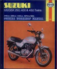
Руководство на английском языке по техническому обслуживанию и ремонту мотоциклов Suzuki GS250/GS400/GS450 и GSX250/GSX400/GSX450 1979-1985 годов выпуска.
- Издательство: Haynes Publishing
- Год издания: 1986
- Страниц: 236
- Формат: PDF
- Размер: 51,6 Mb
Руководство на английском языке по ремонту мотоциклов Suzuki GSX250F.
- Издательство: Suzuki Motor Corporation
- Год издания: 1991
- Страниц: 229
- Формат: PDF
- Размер: 6,9 Mb
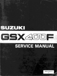
Руководство на английском языке по ремонту мотоциклов Suzuki GSX400F.
- Издательство: Suzuki Motor Corporation
- Год издания: —
- Страниц: 292
- Формат: PDF
- Размер: 39,9 Mb

Руководство на английском языке по техническому обслуживанию и ремонту мотоциклов Suzuki GSX600F, GSX750 и GSX750F 1998-2002 годов выпуска.
- Издательство: Haynes Publishing
- Год издания: 2003
- Страниц: —
- Формат: JPG
- Размер: 64,1 Mb

Руководство на английском языке по техническому обслуживанию и ремонту мотоциклов Suzuki GSX600F Katana, GSX750F Katana, GSX1100F Katana 1988-1996 годов выпуска и GSX-R750, GSX-R1100 1985-1992 годов выпуска.
- Издательство: Haynes Publishing
- Год издания: —
- Страниц: 256
- Формат: PDF
- Размер: 37,5 Mb
Руководство на английском языке по ремонту мотоциклов Suzuki GSF650, GSF650S и GSX650F.
- Издательство: Suzuki Motor Corporation
- Год издания: 2007
- Страниц: 620
- Формат: PDF
- Размер: 28,9 Mb
Руководство на английском языке по ремонту мотоциклов Suzuki GSX750E и GSX750ES 1984-1986 годов выпуска.
- Издательство: Suzuki Motor Corporation
- Год издания: —
- Страниц: 309
- Формат: PDF
- Размер: 18,9 Mb
Руководство на английском языке по ремонту мотоциклов Suzuki GS1150 и GSX1100.
- Издательство: Suzuki Motor Corporation
- Год издания: —
- Страниц: 306
- Формат: PDF
- Размер: 42,4 Mb
Руководство на английском языке по ремонту мотоциклов Suzuki GSX1300BK B-King.
- Издательство: Suzuki Motor Corporation
- Год издания: 2007
- Страниц: 686
- Формат: PDF
- Размер: 35,6 Mb
Руководство на английском языке по ремонту мотоциклов Suzuki GSX1300R.
- Издательство: Suzuki Motor Corporation
- Год издания: —
- Страниц: 645
- Формат: PDF
- Размер: 13,9 Mb
Сборник руководств на английском языке по ремонту мотоциклов Suzuki GSX1300R.
- Издательство: Suzuki Motor Corporation
- Год издания: 1999/2000/2001
- Страниц: 503/31/18
- Формат: PDF
- Размер: 107,6 Mb
Руководство на английском языке по ремонту мотоциклов Suzuki GSX1400.
- Издательство: Suzuki Motor Corporation
- Год издания: 2001
- Страниц: 354
- Формат: PDF
- Размер: 23,6 Mb
Руководство на английском языке по эксплуатации и техническому обслуживанию мотоциклов Suzuki GSX1400.
- Издательство: Suzuki Motor Corporation
- Год издания: —
- Страниц: 37
- Формат: PDF
- Размер: 6,0 Mb


The Cyclepedia.com Suzuki GSX600F Katana and Suzuki GSX750F Katana online service manual features detailed full-color photographs and wiring diagrams, complete specifications with step-by-step procedures performed and written by a Suzuki dealer trained technician.
The Suzuki GSX600F & GSX750F Katana online motorcycle manual will show you how to repair and maintain the following Suzuki GSX600F & GSX750F Katana motorcycles:
1998 Suzuki GSX600FW Katana
1999 Suzuki GSX600FX Katana
2000 Suzuki GSX600FY Katana
2001 Suzuki GSX600FK1 Katana
2002 Suzuki GSX600FK2 Katana
2003 Suzuki GSX600FK3 Katana
2004 Suzuki GSX600FK4 Katana
2005 Suzuki GSX600FK5 Katana
2006 Suzuki GSX600FK6 Katana
2007 Suzuki GSX600FK7 Katana
1998 Suzuki GSX750FW Katana
1999 Suzuki GSX750FX Katana
2000 Suzuki GSX750FY Katana
2001 Suzuki GSX750FK1 Katana
2002 Suzuki GSX750FK2 Katana
2003 Suzuki GSX750FK3 Katana
2004 Suzuki GSX750FK4 Katana
2005 Suzuki GSX750FK5 Katana
2006 Suzuki GSX750FK6 Katana
2007 Suzuki GSX750FK7 Katana
Access the Suzuki GSX600F GSX750F Katana online motorcycle manual NOW by CLICKING HERE – No waiting, no shipping, view it from anywhere, print it out – take it to the garage.
When you subscribe to our Suzuki GSX600F GSX750F Katana online motorcycle manual you’ll instant access to the following information and more! The photos you see here are the same full color quality that you’ll get in our online manual.

Periodic Maintenance – Periodic Maintenance Chart, Clutch Cable Adjustment, Throttle Free Play, Brake Fluid, Engine Idle Speed, Drive Chain Adjustment, Rear Brake Inspection, Brake Pads, Engine Oil, Spark Plugs, Air Filter Servicing, Tires, Valve Clearance, Compression Test

Quick Reference – Katana Specifications, VIN and Engine Number Location, Torque Specifications, General Torque Specifications

Fuel System – Carburetor Removal, Carburetor Installation, Carburetor Assembly, Carburetor Disassembly, Carburetor Synchronization, Carburetor Specifications, Throttle Position Sensor, Fuel Level Sensor, Fuel Strainer, Airbox, Emissions

External Components – Seat, Fuel Tank, Upper Fairings, Lower Fairings, Tail Section, Footpegs, Gearshift Pedal, Handlebar, Front Fender, Rear Fender, Stands, Exhaust System

Engine – Engine Specifications, Camshaft Removal, Camshaft Installation, Cylinder Head Cover, Cylinder Head, Valves, Starter Motor, Cylinders and Pistons, Starter Clutch, Clutch Removal, Clutch Installation, Engine Removal, Engine Installation, Crankcase Splitting, Crankshaft, Crankcase Assembly, Transmission Removal, Transmission Shafts, Transmission Installation, Oil Pump, Gearshift

Lubrication System – Oil Cooler, Oil Pan, Oil Pump, Engine Oil

Final Drive – Drive Chain, Engine Sprocket, Rear Wheel Sprocket

Front Brake – Brake Disc, Master Cylinder, Front Brake Hoses, Front Brake Caliper, Front Brake Specifications

Rear Brake – Master Cylinder, Rear Brake Caliper, Rear Brake Disc

Wheels – Wheel and Axle Inspection, Front Wheel, Rear Wheel, Bearing Replacement

Steering – Removal, Installation

Front Suspension – Fork Removal and Installation, Front Fork Assembly, Front Fork Disassembly

Rear Suspension – Rear Suspension Removal, Rear Suspension Installation, Rear Suspension Disassembly, Rear Suspension Assembly

Electrical Systems – Electrical Specifications, Ignition System, Charging System, Starter System, Switches, Wiring Diagrams
Online Suzuki GSX600F & GSX750F Katana Motorcycle Parts Diagrams
Suzuki GSX600F & GSX750F Katana Motorcycle Troubleshooting
Professional Tech Support
Access the Suzuki GSX600F GSX750F Katana online motorcycle manual NOW by CLICKING HERE – No waiting, no shipping, view it from anywhere, print it out – take it to the garage.
File Specifications:729/729858-katana_1100.pdf file (31 Mar 2023) |
Accompanying Data:
Suzuki Katana 1100 Motorcycle PDF Service Manual (Updated: Friday 31st of March 2023 04:20:47 PM)
Rating: 4.9 (rated by 89 users)
Compatible devices: GS500E, VL1500, 1989 GS500EK, Intruder VS600GL, VZR1800/BZ, VZ1600K4, SV1000, FA50.
Recommended Documentation:
Service Manual (Text Version):
(Ocr-Read Summary of Contents of some pages of the Suzuki Katana 1100 Document (Main Content), UPD: 31 March 2023)
-
36, ENGINE 3-6 • Remove the oil cooler by removing the mounting bolts. • Remove the gearshift lever by removing the mounting bolt. ~ ~l • Remove the engine sprocket cover by removing the bolts. CAUTION: Do not operate the clutch lever to prevent clutch piston retainer damage. • Flatten the engine sprocket nut lock washer by using chisel. • Remove th…
-
157, ——— CHASSIS 7-10 FRONT BRAKE ,———————————_._._ i -, .. Tightening torque Item T—-N·m -1- kg~m I ·Ib-i»t —+— -_ .. — ————r-~- — — ——-1—— — —— I 8-12 ; 0.8-12 I 6.0-85 —-+— — ——__+_ ———- .. —l— — — ® : 20 — 25 2.0- 2.5 I 14.5 — 180 —: f=—-:—=-: —-T-~-.:—=~-::-l :~=~ I—=~—H:: ~~ J?::~~ ~ ~:~ ~:% r j— -8 c —— l i BRAKE PAD REPLACEMEI\lT • Remove the …
-
219, SERVICING INFORMATION 8-22 TIGHTENING TORQUE ENGINE ITEM N’m kg-m Ib-ft Cylinder head cover bolt and union bolt 13 — 15 1.3 — 1.5 9.5 — 11.0 Cylinder head nut 35 — 40 3.5 — 4.0 25.5 — 29.0 Cylinder head bolt 7 — 1 1 0.7 — 1.1 5.0 — 8.0 Cylinder base nut 7 — 11 0.7 — 1.1 5.0 — 8.0 Cylinder stud bolt 13 — 16 1.3 — 1.6 9.5 — 11.5 Valve clearance adjuster lock nut 9 — 1 1 0.9 — 1. 1 6.5 — 8.0 Camshaf…
-
158, 7-11 CHASSIS CALIPER REMOVAL AND DISASSEMBLY • Disconnect the brake hose off the brake caliper and catch the brake fluid in a suitable receptacle. CAUTION: Never re-use the brake fluid left over from the servicing and stored for long periods. WARNING: Brake fluid. if it leaks. will interfere with safe running and discolor painted surfaces. Check the brake hose and hose joint for cracks and oil leakage. • Remove …
-
66, ENGINE 3-36 • When mounting the conrad on the crankshaft, make sure that numeral figure CD of the conrad faces rearward. • Tighten the conrad fitting nuts with specified torque. Tightening torque: 49 — 53 N’m (4.9 — 5.3 kg-m. 35.5 — 38.5 Ib-ft) • Check the control for smooth turning. CRAN KCASE-CRAN KSHAFT BEARING SELECTION • Inspect each bearing of upper and lower crankcases for any damage…
-
135, Suzuki Katana 1100 6-13 ELECTRICAL SYSTEM ARMATURE COIL Using a pocket tester, check the coil for open and ground by placing probe pins on each commutator segment and rotor core (to test for ground) and on any two segments at various places (to test for open), with the brushes lifted off the commutator surface. If the coil is found to be open-circuited or grounded replace the armature. C…
-
186, 7-39 CHASSIS INSTALLATION Any dust or rust around the valve hole must be cleaned off. Then install the valve in the rim. CAUTION: When installing the valve, tighten the nut (i) by hand as much as possible. Holding the nut under this condition, tighten the lock nut@. Do not overtighten nut (i) as this may distort the rubber packing and cause an air leak. —- -, ‘I I Wheel I I l J !L- J TI…
-
92, ENGINE 3-62 • Each camshaft journal holder is identified with a cast-on letter. Install the dowel pins to each camshaft journal holder. • Secure the ten camshaft journal holders evenly by tightening the camshaft journal holder bolts sequentially. Try to equal- ize the pressure by moving the wrench diagonally from one bolt to another and from one camshaft journal holder to another, to push …
-
104, FUEL AND LUBRICATION SYSTEM 4-8 FUEL SYSTEM When turning starter motor, negative pressure is generated in the combustion chamber. This negative pressure works on the diaphram of fuel cock through passageway provided in the carburetor main bore and vacuum pipe, and diaphragm builds up a negative pressure which is higher than the spring pressure. Fuel valve is forced to open due to diaphragm operation,…
-
181, CHASSIS 7-34 DAMPER Inspect the dampers for wear and damage. REASSEMBLY AND REMOUNTING Reassemble and remount the rear wheel in the reverse order of removal and disassembly. Pay attention to the following points: WHEEL BEARING • Apply grease to the bearings before installing. 99000-25030: SUZUKI super grease «A» • Install the wheel bearings by using the special tools. 09941-34513: Bearing installer set NOTE: …
-
198, — — 8-1 SERVICING INFORMATION TROUBLESHOOTING ENGINE Complaint Symptom and possible causes Remedy ———————————+—————— Engine will not start, Compression too low or is hard to start. 1. Valve clearance out of adjustment. Adjust. 2. Worn valves guides or poor seating of valves. Repair, or replace. 3. Valves mistiming. Adjust. 4. Piston r…
-
65, 3-35 ENGINE Conrod 1.0. specification Code 1.0. specification 1 41.000 (1.6142 — 41.008 mm — 1.6145 in) 2 41.008 (1.6145 — 41.016 mm — 1.6148 in) Crank pin 0.0. specification Code 0.0. specification 1 37.992 (1.4957 — 38.000 mm — 1.4961 in) 2 37.984 (1.4954 — 37.992 mm — 1.4957 in) 3 37.976 (1.4951 — 37.984 mm — 1.4954 in) 09900-20202: Micrometer (25 — 50 mm) Bearing thickness Color (P…
-
149, Suzuki Katana 1100 CHASSIS 7-2 • Remove the lower fairing assembly by removing the screws. 09900-00401: L-type hexagon wrench set • Remove the upper fairing assembly by removing the screws. 09900-00401: L-type hexagon wrench set REINSTALLATION Reinstall the fairing in the reverse order of removal.
… -
143, 6-21 ELECTRICAL SYSTEM OIL PRESSURE SWITCH WIRE COLOR • Continuity, when engine is stopped. Gr • No continuity, when engine is running. Br W ~:=—~_~ __ .. GI! c- __ _G r_o_u_n~ Y ON I ‘J- -0 Y IW f——- … —+— —— OFF \ B Lbl Lg NOTE: G Before inspecting the oil pressure switch, check B/W the engine oil level at oil inspection window. O/W YIG O/G WINDOW SCREEN SWITCH BI ~~ I WIG i 0 1 W/R G/Y f—— 0—-…
-
Suzuki Katana 1100 User Manual
-
Suzuki Katana 1100 User Guide
-
Suzuki Katana 1100 PDF Manual
-
Suzuki Katana 1100 Owner’s Manuals
Recommended: NOBO X25M, JWE-2400CUA-L-25B, NetVito 5300 Series, 243-645B000
Links & Tools
Operating Impressions, Questions and Answers:
Home /
Motorcycle Repair Service Manuals
/ Suzuki
/ GSX1100F Katana
Suzuki GSX1100F Katana Service Repair Manuals on Motor Era

Motor Era offers service repair manuals for your Suzuki GSX1100F Katana — DOWNLOAD your manual now! Suzuki GSX1100F Katana service repair manuals
Complete list of Suzuki GSX1100F Katana motorcycle service repair manuals:
Suzuki GSX1100F Katana 1987-1993 Service Repair Manual
Suzuki GSX1100F Katana 1987-1993 Service Repair Manual PDF
Suzuki GSX1100F Katana 1987-1993 Factory Service Manual PDF
Suzuki GSX1100F Katana 1987-1993 Repair Service Manual PDF
Suzuki GSX1100F Katana 1987-1993 Service Repair Manual
Suzuki GSX1100F Katana 1987-1993 Repair Service Manual
Suzuki GSX1100F Katana 1988-1995 Workshop Service Manual
Suzuki GSX1100F Katana 1987-1993 Workshop Service Manual
1988-1994 Suzuki GSX1100F Service Repair Manual DOWNLOAD 1988 1989 1990 1991 1992 1993 1994
1989-1994 Suzuki GSX1100F Service Repair Manual INSTANT DOWNLOAD
1988-1994 Suzuki GSX1100F Service Repair Manual DOWNLOAD
1988-1994 Suzuki GSX1100F Katana Motorcycle Workshop Repair & Service Manual [COMPLETE & INFORMATIVE for DIY REPAIR] ☆ ☆ ☆ ☆ ☆
Suzuki Katana 1100 GSX1100F Motorcycle Complete Workshop Service Repair Manual 1987 1988 1989 1990 1991 1992 1993
SUZUKI GSX1100F MOTORCYCLE SERVICE & REPAIR MANUAL (1989 1990 1991 1992 1993 1994) — DOWNLOAD!
Suzuki Katana 1100 GSX1100F Service Repair Manual Download
Suzuki GSX1100F (GSX1100FJ, GSX1100FK, GSX1100FL, GSX1100FM, GSX1100FN, GSX1100FP, GSX1100FR) Katana Motorcycle Workshop Service Repair Manual 1988-1994
DOWNLOAD NOW Suzuki GSX1100F GSX 1100F Katana 88-94 GSX1100 Service Repair Workshop Manual
SUZUKI GSX600F GSX750F GSX1100F KATANA SERVICE REPAIR MANUAL PDF 1987-1993
SUZUKI GSX600F GSX750F GSX1100F KATANA PDF SERVICE REPAIR WORKSHOP MANUAL 1987-1993
SUZUKI GSX600F GSX750F GSX1100F KATANA SERVICE REPAIR MANUAL 1987-1993
SUZUKI KATANA 1100 GSX1100F SERVICE REPAIR PDF MANUAL DOWNLOAD 1987-1993
SUZUKI KATANA 1100 GSX1100F FULL SERVICE & REPAIR MANUAL 1987-1993
SUZUKI GSX600F GSX750F GSX1100F KATANA FULL SERVICE & REPAIR MANUAL 1987-1993
Suzuki GSX600F GSX750F GSX1100F Katana Workshop Manual 1987 1988 1989 1990 1991 1992 1993
SUZUKI GSX600F GSX750F GSX1100F KATANA SERVICE REPAIR WORKSHOP MANUAL 1987-1993
SUZUKI GSX600F GSX750F GSX1100F KATANA WORKSHOP REPAIR MANUAL DOWNLOAD 1987-1993
SUZUKI GSX600F GSX750F GSX1100F KATANA SERVICE REPAIR PDF MANUAL DOWNLOAD 1987-1993