![]()
Ninja ZX-10R
Ninja ZX-10R ABS
Motorcycle
Service Manual

Quick Reference Guide
This quick reference guide will assist you in locating a desired topic or procedure.
•Bend the pages back to match the black tab of the desired chapter number with the black tab on the edge at each table of contents page.
•Refer to the sectional table of contents for the exact pages to locate the specific topic required.
|
General Information |
1 |
j |
|
Periodic Maintenance |
2 |
j |
|
Fuel System (DFI) |
3 |
j |
|
Cooling System |
4 |
j |
|
Engine Top End |
5 |
j |
|
Clutch |
6 |
j |
|
Engine Lubrication System |
7 |
j |
|
Engine Removal/Installation |
8 |
j |
|
Crankshaft/Transmission |
9 |
j |
|
Wheels/Tires |
10 |
j |
|
Final Drive |
11 |
j |
|
Brakes |
12 |
j |
|
Suspension |
13 |
j |
|
Steering |
14 |
j |
|
Frame |
15 |
j |
|
Electrical System |
16 |
j |
|
Self-Diagnosis System |
17 |
j |
|
Appendix |
18 |
j |

Ninja ZX-10R
Ninja ZX-10R ABS
Motorcycle
Service Manual
All rights reserved. No parts of this publication may be reproduced, stored in a retrieval system, or transmitted in any form or by any means, electronic mechanical photocopying, recording or otherwise, without the prior written permission of Quality Assurance Division/Motorcycle & Engine Company/Kawasaki Heavy Industries, Ltd., Japan.
No liability can be accepted for any inaccuracies or omissions in this publication, although every possible care has been taken to make it as complete and accurate as possible.
The right is reserved to make changes at any time without prior notice and without incurring an obligation to make such changes to products manufactured previously. See your Motorcycle dealer for the latest information on product improvements incorporated after this publication.
All information contained in this publication is based on the latest product information available at the time of publication. Illustrations and photographs in this publication are intended for reference use only and may not depict actual model component parts.
|
© 2010 Kawasaki Heavy Industries, Ltd. |
4th Edition (0) : Aug. 7, 2012 |

LIST OF ABBREVIATIONS
|
A |
ampere(s) |
lb |
pound(s) |
|
ABDC |
after bottom dead center |
m |
meter(s) |
|
AC |
alternating current |
min |
minute(s) |
|
ATDC |
after top dead center |
N |
newton(s) |
|
BBDC |
before bottom dead center |
Pa |
pascal(s) |
|
BDC |
bottom dead center |
PS |
horsepower |
|
BTDC |
before top dead center |
psi |
pound(s) per square inch |
|
°C |
degree(s) Celsius |
r |
revolution |
|
DC |
direct current |
rpm |
revolution(s) per minute |
|
F |
farad(s) |
TDC |
top dead center |
|
°F |
degree(s) Fahrenheit |
TIR |
total indicator reading |
|
ft |
foot, feet |
V |
volt(s) |
|
g |
gram(s) |
W |
watt(s) |
|
h |
hour(s) |
Ω |
ohm(s) |
|
L |
liter(s) |
COUNTRY AND AREA CODES
|
AT |
Austria |
|
|
AU |
Australia |
|
|
BR |
Brazil |
|
|
CA |
Canada |
|
|
CAL |
California |
|
|
CH |
Switzerland |
|
|
DE |
Germany |
|
|
EUR |
Europe |
|
GB
PH SEA-B1
SEA-B2 US
WVTA (FULL H)
GB WVTA (FULL H)
WVTA (78.2 H)
United Kingdom Philippines
Southeast Asia B1 (with Evaporative Emission Control System)
Southeast Asia B2 United States
WVTA Model with Honeycomb Catalytic Converter (Full Power)
WVTA Model with Honeycomb Catalytic Converter (Left Side Traffic Full Power)
WVTA Model with Honeycomb Catalytic Converter (Restricted Power)

EMISSION CONTROL INFORMATION
To protect the environment in which we all live, Kawasaki has incorporated crankcase emission (1) and exhaust emission (2) control systems in compliance with applicable regulations of the United States Environmental Protection Agency and California Air Resources Board. Additionally, Kawasaki has incorporated an evaporative emission control system (3) in compliance with applicable regulations of the California Air Resources Board on vehicles sold in California only.
1. Crankcase Emission Control System
This system eliminates the release of crankcase vapors into the atmosphere. Instead, the vapors are routed through an oil separator to the intake side of the engine. While the engine is operating, the vapors are drawn into combustion chamber, where they are burned along with the fuel and air supplied by the fuel injection system.
2. Exhaust Emission Control System
This system reduces the amount of pollutants discharged into the atmosphere by the exhaust of this motorcycle. The fuel, ignition, and exhaust systems of this motorcycle have been carefully designed and constructed to ensure an efficient engine with low exhaust pollutant levels.
The exhaust system of this model motorcycle manufactured primarily for sale in California includes a catalytic converter system.
3. Evaporative Emission Control System
Vapors caused by fuel evaporation in the fuel system are not vented into the atmosphere. Instead, fuel vapors are routed into the running engine to be burned, or stored in a canister when the engine is stopped. Liquid fuel is caught by a vapor separator and returned to the fuel tank.
The Clean Air Act, which is the Federal law covering motor vehicle pollution, contains what is commonly referred to as the Act’s “tampering provisions”.
“Sec. 203(a) The following acts and the causing thereof are prohibited…
(3)(A) for any person to remove or render inoperative any device or element of design installed on or in a motor vehicle or motor vehicle engine in compliance with regulations under this title prior to its sale and delivery to the ultimate purchaser, or for any manufacturer or dealer knowingly to remove or render inoperative any such device or element of design after such sale and delivery to the ultimate purchaser.
(3)(B) for any person engaged in the business of repairing, servicing, selling, leasing, or trading motor vehicles or motor vehicle engines, or who operates a fleet of motor vehicles knowingly to remove or render inoperative any device or element of design installed on or in a motor vehicle or motor vehicle engine in compliance with regulations under this title following its sale and delivery to the ultimate purchaser…”
NOTE
○The phrase “remove or render inoperative any device or element of design” has been generally interpreted as follows.
1.Tampering does not include the temporary removal or rendering inoperative of devices or elements of design in order to perform maintenance.
2.Tampering could include.
a.Maladjustment of vehicle components such that the emission standards are exceeded.
b.Use of replacement parts or accessories which adversely affect the performance or durability of the motorcycle.
c.Addition of components or accessories that result in the vehicle exceeding the standards.
d.Permanently removing, disconnecting, or rendering inoperative any component or element of design of the emission control systems.
WE RECOMMEND THAT ALL DEALERS OBSERVE THESE PROVISIONS OF FEDERAL LAW, THE VIOLATION OF WHICH IS PUNISHABLE BY CIVIL PENALTIES NOT EXCEEDING $10 000 PER VIOLATION.

TAMPERING WITH NOISE CONTROL SYSTEM PROHIBITED
Federal law prohibits the following acts or the causing thereof. (1) The removal or rendering inoperative by any person other than for purposes of maintenance, repair, or replacement, of any device or element of design incorporated into any new vehicle for the purpose of noise control prior to its sale or delivery to the ultimate purchaser or while it is in use, or (2) the use of the vehicle after such device or element of design has been removed or rendered inoperative by any person.
Among those acts presumed to constitute tampering are the acts listed below.
•Replacement of the original exhaust system or muffler with a component not in compliance with Federal regulations.
•Removal of the muffler(s) or any internal portion of the muffler(s).
•Removal of the air box or air box cover.
•Modifications to the muffler(s) or air intake system by cutting, drilling, or other means if such modifications result in increased noise levels.

Foreword
This manual is designed primarily for use by trained mechanics in a properly equipped shop. However, it contains enough detail and basic information to make it useful to the owner who desires to perform his own basic maintenance and repair work. A basic knowledge of mechanics, the proper use of tools, and workshop procedures must be understood in order to carry out maintenance and repair satisfactorily. Whenever the owner has insufficient experience or doubts his ability to do the work, all adjustments, maintenance, and repair should be carried out only by qualified mechanics.
In order to perform the work efficiently and to avoid costly mistakes, read the text, thoroughly familiarize yourself with the procedures before starting work, and then do the work carefully in a clean area. Whenever special tools or equipment are specified, do not use makeshift tools or equipment. Precision measurements can only be made if the proper instruments are used, and the use of substitute tools may adversely affect safe operation.
For the duration of the warranty period, we recommend that all repairs and scheduled maintenance be performed in accordance with this service manual. Any owner maintenance or repair procedure not performed in accordance with this manual may void the warranty.
To get the longest life out of your vehicle.
•Follow the Periodic Maintenance Chart in the Service Manual.
•Be alert for problems and non-scheduled maintenance.
•Use proper tools and genuine Kawasaki Motorcycle parts. Special tools, gauges, and testers that are necessary when servicing Kawasaki motorcycles are introduced by the Service Manual. Genuine parts provided as spare parts are listed in the Parts Catalog.
•Follow the procedures in this manual carefully. Don’t take shortcuts.
•Remember to keep complete records of maintenance and repair with dates and any new parts installed.
How to Use This Manual
In this manual, the product is divided into its major systems and these systems make up the manual’s chapters. The Quick Reference
Guide shows you all of the product’s system and assists in locating their chapters. Each chapter in turn has its own comprehensive Table of Contents.
For example, if you want ignition coil information, use the Quick Reference Guide to locate the Electrical System chapter. Then, use the Table of Contents on the first page of the chapter to find the Ignition Coil section.
Whenever you see symbols, heed their instructions! Always follow safe operating and maintenance practices.

 DANGER
DANGER indicates a hazardous situation which, if not avoided, will result in death or serious injury.
 WARNING
WARNING indicates a hazardous situation which, if not avoided, could result in death or serious injury.
NOTICE
NOTICE is used to address practices not related to personal injury.
This manual contains four more symbols which will help you distinguish different types of information.
NOTE
○This note symbol indicates points of particular interest for more efficient and convenient operation.
•Indicatesdone. a procedural step or work to be ○Indicates a procedural sub-step or how to do the work of the procedural step it follows. It
also precedes the text of a NOTE.
 Indicates a conditional step or what action to take based on the results of the test or inspection in the procedural step or sub-step it follows.
In most chapters an exploded view illustration of the system components follows the Table of Contents. In these illustrations you will find the instructions indicating which parts require specified tightening torque, oil, grease or a locking agent during assembly.
![]()
GENERAL INFORMATION 1-1
General Information |
|||
|
Table of Contents |
|||
|
1 |
|||
|
Before Servicing |
1-2 |
||
|
Model Identification………………………………………………………………………………………………….. |
1-7 |
||
|
General Specifications……………………………………………………………………………………………… |
1-11 |
||
|
Technical Information-Sport-Kawasaki TRaction Control System (S-KTRC) ……………………. |
1-14 |
||
|
Technical Information-Power Mode ……………………………………………………………………………. |
1-17 |
||
|
Technical Information-Kawasaki Intelligent anti-lock Brake System (KIBS/ZX1000K model |
|||
|
only)……………………………………………………………………………………………………………………. |
1-19 |
||
|
Technical Information — Electronic Steering Damper (ESD/ZX1000JD/KD models) ………….. |
1-23 |
||
|
Unit Conversion Table ……………………………………………………………………………………………… |
1-26 |
1-2 GENERAL INFORMATION
Before Servicing
Before starting to perform an inspection service or carry out a disassembly and reassembly operation on a motorcycle, read the precautions given below. To facilitate actual operations, notes, illustrations, photographs, cautions, and detailed descriptions have been included in each chapter wherever necessary. This section explains the items that require particular attention during the removal and reinstallation or disassembly and reassembly of general parts.
Especially note the following.
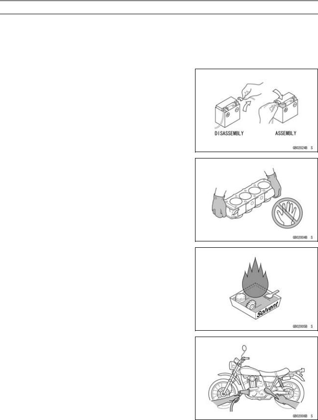
Battery Ground
Before completing any service on the motorcycle, disconnect the battery cables from the battery to prevent the engine from accidentally turning over. Disconnect the ground cable (–) first and then the positive (+). When completed with the service, first connect the positive (+) cable to the positive (+) terminal of the battery then the negative (–) cable to the negative terminal.
Edges of Parts
Lift large or heavy parts wearing gloves to prevent injury from possible sharp edges on the parts.
Solvent
Use a high flash-point solvent when cleaning parts. High flash-point solvent should be used according to directions of the solvent manufacturer.
Cleaning Vehicle before Disassembly
Clean the vehicle thoroughly before disassembly. Dirt or other foreign materials entering into sealed areas during vehicle disassembly can cause excessive wear and decrease performance of the vehicle.
GENERAL INFORMATION 1-3
Before Servicing
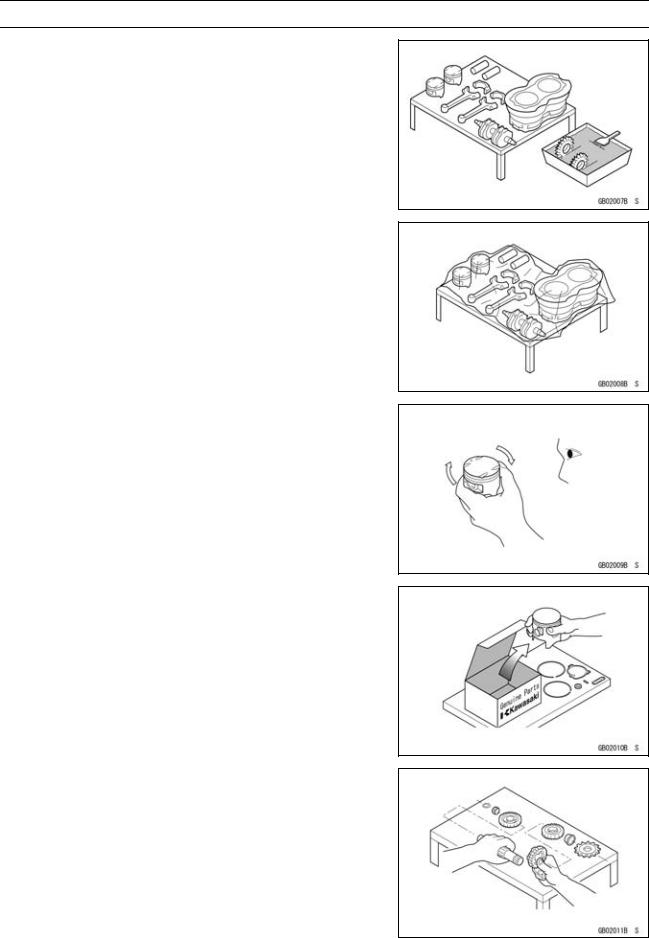
Arrangement and Cleaning of Removed Parts
Disassembled parts are easy to confuse. Arrange the parts according to the order the parts were disassembled and clean the parts in order prior to assembly.
Storage of Removed Parts
After all the parts including subassembly parts have been cleaned, store the parts in a clean area. Put a clean cloth or plastic sheet over the parts to protect from any foreign materials that may collect before re-assembly.
Inspection
Reuse of worn or damaged parts may lead to serious accident. Visually inspect removed parts for corrosion, discoloration, or other damage. Refer to the appropriate sections of this manual for service limits on individual parts. Replace the parts if any damage has been found or if the part is beyond its service limit.
Replacement Parts
Replacement parts must be KAWASAKI genuine or recommended by KAWASAKI. Gaskets, O-rings, oil seals, grease seals, circlips, cotter pins or self-locking nuts must be replaced with new ones whenever disassembled.
Assembly Order
In most cases assembly order is the reverse of disassembly, however, if assembly order is provided in this Service Manual, follow the procedures given.
1-4 GENERAL INFORMATION
Before Servicing
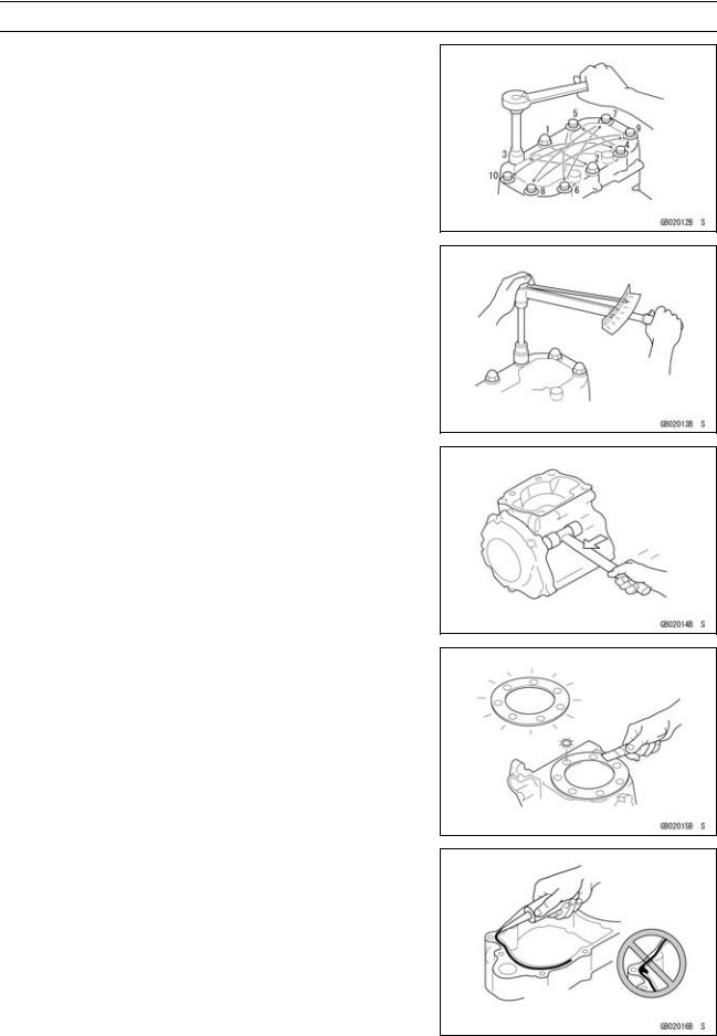
Tightening Sequence
Generally, when installing a part with several bolts, nuts, or screws, start them all in their holes and tighten them to a snug fit. Then tighten them according to the specified sequence to prevent case warpage or deformation which can lead to malfunction. Conversely when loosening the bolts, nuts, or screws, first loosen all of them by about a quarter turn and then remove them. If the specified tightening sequence is not indicated, tighten the fasteners alternating diagonally.
Tightening Torque
Incorrect torque applied to a bolt, nut, or screw may lead to serious damage. Tighten fasteners to the specified torque using a good quality torque wrench.
Force
Use common sense during disassembly and assembly, excessive force can cause expensive or hard to repair damage. When necessary, remove screws that have a non -permanent locking agent applied using an impact driver. Use a plastic-faced mallet whenever tapping is necessary.
Gasket, O-ring
Hardening, shrinkage, or damage of both gaskets and O-rings after disassembly can reduce sealing performance. Remove old gaskets and clean the sealing surfaces thoroughly so that no gasket material or other material remains. Install the new gaskets and replace the used O-rings when re-assembling.
Liquid Gasket, Non-permanent Locking Agent
For applications that require Liquid Gasket or a Non-permanent Locking Agent, clean the surfaces so that no oil residue remains before applying liquid gasket or non-permanent locking agent. Do not apply them excessively. Excessive application can clog oil passages and cause serious damage.
GENERAL INFORMATION 1-5
Before Servicing
Press
For items such as bearings or oil seals that must be pressed into place, apply small amount of oil to the contact area. Be sure to maintain proper alignment and use smooth movements when installing.
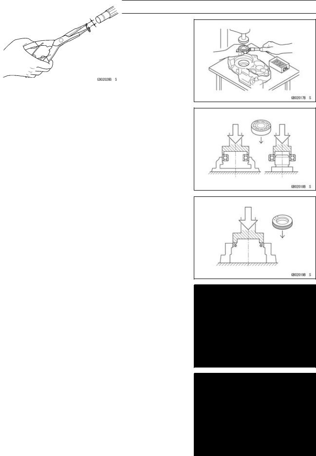
Ball Bearing and Needle Bearing
Do not remove pressed ball or needle unless removal is absolutely necessary. Replace with new ones whenever removed. Press bearings with the manufacturer and size marks facing out. Press the bearing into place by putting pressure on the correct bearing race as shown.
Pressing the incorrect race can cause pressure between the inner and outer race and result in bearing damage.
Oil Seal, Grease Seal
Do not remove pressed oil or grease seals unless removal is necessary. Replace with new ones whenever removed. Press new oil seals with manufacture and size marks facing out. Make sure the seal is aligned properly when installing.
Apply specified grease to the lip of seal before installing the seal.
Circlips, Cotter Pins
Replace the circlips or cotter pins that were removed with new ones. Take care not to open the clip excessively when installing to prevent deformation.
1-6 GENERAL INFORMATION
Before Servicing
Lubrication
It is important to lubricate rotating or sliding parts during assembly to minimize wear during initial operation. Lubrication points are called out throughout this manual, apply the specific oil or grease as specified.
Direction of Engine Rotation
When rotating the crankshaft by hand, the free play amount of rotating direction will affect the adjustment. Rotate the crankshaft to positive direction (clockwise viewed from output side).
Electrical Leads
A two-color lead is identified first by the primary color and then the stripe color. Unless instructed otherwise, electrical leads must be connected to those of the same color.
Instrument
Use a meter that has enough accuracy for an accurate measurement. Read the manufacture’s instructions thoroughly before using the meter. Incorrect values may lead to improper adjustments.
GENERAL INFORMATION 1-7
Model Identification
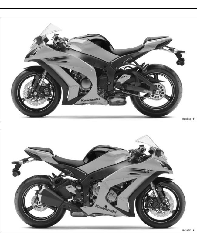
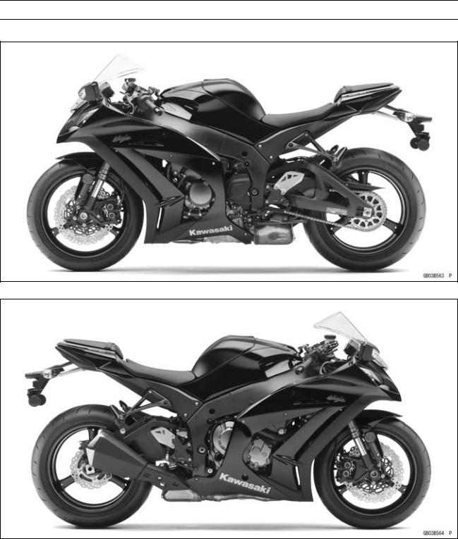
ZX1000JB (US and CA Models) Left Side View
ZX1000JB (US and CA Models) Right Side View
1-8 GENERAL INFORMATION
Model Identification
ZX1000JB (EUR Models) Left Side View
ZX1000JB (EUR Models) Right Side View
GENERAL INFORMATION 1-9
Model Identification
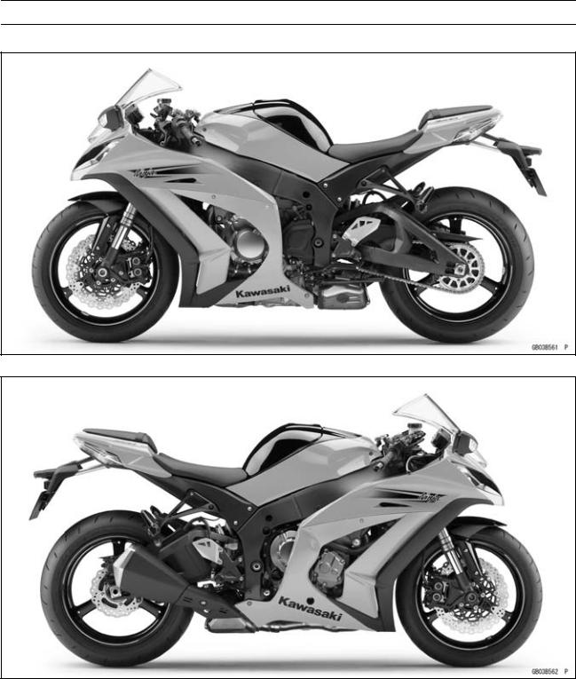
ZX1000KB (US and CA Models) Left Side View
ZX1000KB (US and CA Models) Right Side View

1-10 GENERAL INFORMATION
Model Identification
ZX1000KB (EUR Models) Left Side View
ZX1000KB (EUR Models) Right Side View
|
Frame Number |
Engine Number |
|
|
GENERAL INFORMATION 1-11 |
|
General Specifications |
|
|
Items |
ZX1000JB JD/KB KD |
|
Dimensions |
|
|
Overall Length |
2 075 mm (81.69 in.) |
|
Overall Width |
715 mm (28.1 in.) |
|
Overall Height |
1 115 mm (43.90 in.) |
|
Wheelbase |
1 425 mm (56.10 in.) |
|
Road Clearance |
135 mm (5.31 in.) |
|
Seat Height |
813 mm (32.0 in.) |
|
Curb Mass: |
|
|
(ZX1000J Model) |
198 kg (437 lb) |
|
Front |
103 kg (227 lb) |
|
Rear |
95 kg (209 lb) |
|
(ZX1000K Model) |
201 kg (443 lb) |
|
Front |
104 kg (229 lb) |
|
Rear |
97 kg (214 lb) |
|
Fuel Tank Capacity |
17 L (4.5 US gal) |
|
Performance |
|
|
Minimum Turning Radius |
3.4 m (11.2 ft) |
|
Engine |
|
|
Type |
4-stroke, DOHC, 4-cylinder |
|
Cooling System |
Liquid-cooled |
|
Bore and Stroke |
76.0 × 55.0 mm (3.0 × 2.2 in.) |
|
Displacement |
998 cm³ (60.9 cu in.) |
|
Compression Ratio |
13.0:1 |
|
Maximum Horsepower |
|
|
147.1 kW (200 PS) @13 000 r/min (rpm) |
|
|
(WVTA (78.2 H)) 78.2 kW (106 PS) @12 500 r/min (rpm) |
|
|
(SEA-B1/B2) 111 kW (151 PS) @10 000 r/min (rpm) |
|
|
(US, CA, CAL) – – – |
|
|
Maximum Torque |
112 N·m (11.4 kgf·m, 82.6 ft·lb) @11 500 r/min (rpm) |
|
(WVTA (78.2 H)) 78 N·m (8.0 kgf·m, 57.5 ft·lb) @5 200 r/min |
|
|
(rpm) |
|
|
(SEA-B1/B2) 106 N·m (10.8 kgf·m, 78.2 ft·lb) @10 000 r/min |
|
|
(rpm) |
|
|
(US, CA, CAL) – – – |
|
|
Fuel System |
FI (Fuel Injection), KEIHIN TTK47 × 4 |
|
Starting System |
Electric starter |
|
Ignition System |
Battery and coil (transistorized) |
|
Timing Advance |
Electronically advanced (IC igniter in ECU) |
|
Ignition Timing: |
|
|
( ZX1000JC/KC) |
10° BTDC @1 100 r/min (rpm) |
|
(ZX1000JD/KD) |
10° BTDC @1 100 r/min (rpm) 42.5° BTDC @10 500 r/min |
|
(rpm) |
|
|
Spark Plug |
NGK CR9EIA-9 |
|
Cylinder Numbering Method |
Left to right, 1-2-3-4 |
|
Firing Order |
1-2-4-3 |

1-12 GENERAL INFORMATION
General Specifications
|
Items |
ZX1000JB JD/KB KD |
|
Valve Timing: |
|
|
Intake: |
|
|
Open |
36° (BTDC) |
|
Close |
80° (ABDC) |
|
Duration |
296° |
|
Exhaust: |
|
|
Open |
74° (BBDC) |
|
Close |
39° (ATDC) |
|
Duration |
293° |
|
Lubrication System |
Forced lubrication (wet sump with oil cooler) |
|
Engine Oil: |
|
|
Type |
API SG, SH, SJ, SL or SM with JASO MA, MA1 or MA2 |
|
Viscosity |
SAE 10W-40 |
|
Capacity |
3.7 L (3.9 US qt) |
|
Drive Train |
|
|
Primary Reduction System: |
|
|
Type |
Gear |
|
Reduction Ratio |
1.681 (79/47) |
|
Clutch Type |
Wet multi disc |
|
Transmission: |
|
|
Type |
6-speed, constant mesh, return shift |
|
Gear Ratios: |
|
|
1st |
2.600 (39/15) |
|
2nd |
|
|
2.053 (39/19) |
|
|
3rd |
1.737 (33/19) |
|
4th |
1.571 (33/21) |
|
5th |
1.444 (26/18) |
|
6th |
1.348 (31/23) |
|
Final Drive System: |
|
|
Type |
Chain drive |
|
Reduction Ratio |
2.294 (39/17) |
|
Overall Drive Ratio |
5.197 @Top gear |
|
Frame |
|
|
Type |
Tubular, diamond |
|
Caster (Rake Angle) |
25° |
|
Trail |
107 mm (4.21 in.) |
|
Front Tire: |
|
|
Type |
Tubeless |
|
Size |
120/70 ZR17 M/C (58W) |
|
Rim Size |
J17M/C × MT3.50 |
|
Rear Tire: |
|
|
Type |
Tubeless |
|
Size |
190/55 ZR17 M/C (75W) |
|
Rim Size |
J17M/C × MT6.00 |
|
GENERAL INFORMATION 1-13 |
|
|
General Specifications |
|
|
Items |
ZX1000JB JD/KB KD |
|
Front Suspension: |
|
|
Type |
Telescopic fork (upside-down) |
|
Wheel Travel |
120 mm (4.72 in.) |
|
Rear Suspension: |
|
|
Type |
Swingarm (horizontal back-link) |
|
Wheel Travel |
140 mm (5.51 in.) |
|
Brake Type: |
|
|
Front |
Dual discs |
|
Rear |
Single disc |
|
Electrical Equipment |
|
|
Battery: |
|
|
(ZX1000J Model) |
12 V 6 Ah |
|
(ZX1000K Model) |
12 V 8.6 Ah |
|
Headlight: |
|
|
Type |
Semi-sealed beam |
|
Bulb: |
|
|
High |
12 V 55 W (quartz-halogen) × 2 |
|
Low |
12 V 55 W (quartz-halogen) |
|
Tail/Brake Light |
LED |
|
Alternator: |
|
|
Type |
Three-phase AC |
|
Rated Output |
30 A/14 V @5 000 r/min (rpm) |
Specifications are subject to change without notice, and may not apply to every country.

1-14 GENERAL INFORMATION
Technical Information-Sport-Kawasaki TRaction Control System (S-KTRC)
Overview
S-KTRC is a highly sophisticated system based on MotoGP racing technology. Unlike the KTRC system used on the GTR1400 ABS (Concours 14 ABS in N. America), which is designed to offer rider reassurance when traversing slippery surfaces, S-KTRC, is designed to maximize forward motion, allowing riding at the edge of traction.
The quickest acceleration requires a certain amount of slip, so in order to optimize traction, S-KTRC actually allows slip. The ideal slip ratio varies according to conditions. The system looks at a number of parameters to get an accurate real-time picture of what is going on: front and rear wheel speed (slippage), engine rpm, throttle position, slippage, acceleration, etc.
Using complex analysis, the system is able to predict when traction conditions are about to become unfavorable. By acting before slippage exceeds the range for optimal traction, drops in power can be minimized resulting in ultra-smooth operation.
There are three available modes that riders can set according to preference (and skill level). Each mode is able to accommodate a range of riding conditions. Of course, engine manageability is such that riders can opt to turn the system OFF without fear of making the bike uncontrollable.
By combining the setting with the power mode, the rider can choose various riding modes to suit the road conditions and riding skill.
The system becomes functional at 5 km/h (3.1 mph) or more. If a failure occurs in the system, the warning indicator light (yellow LED) and mode indicator symbol blink to let the rider know that the system stops functioning.
GENERAL INFORMATION 1-15
Technical Information-Sport-Kawasaki TRaction Control System (S-KTRC)
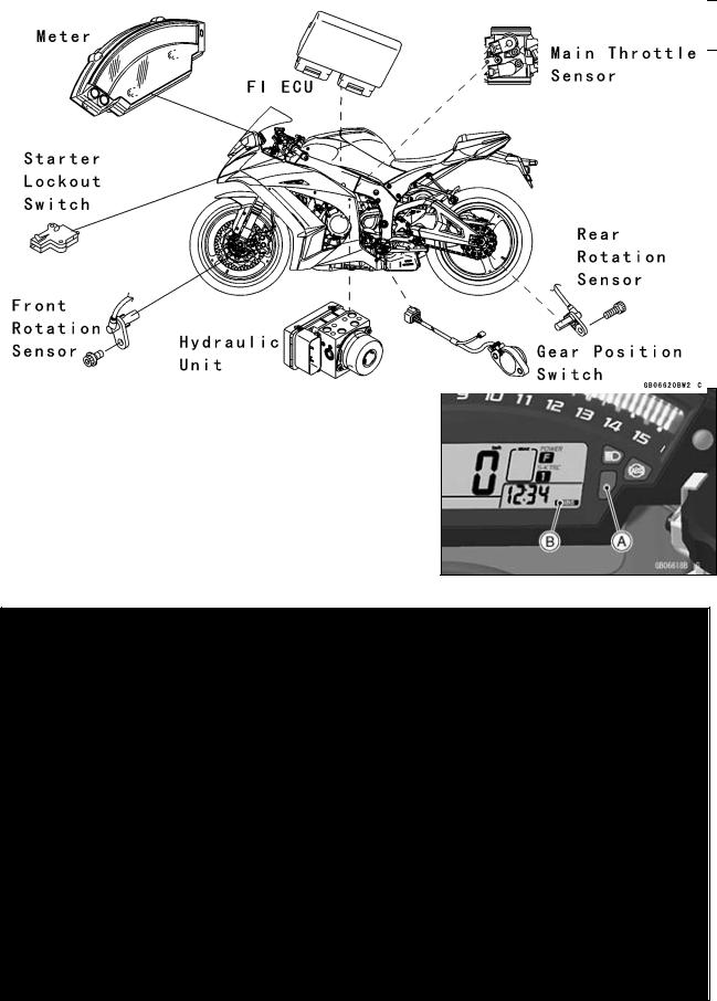
System Components
1. FI ECU
The FI ECU analyzes the motorcycle conditions based on the signals from the front/rear wheel rotation sensors and FI sensors (such as the crankshaft sensor and main throttle sensor), and controls engine power by reducing the number of ignition and retarding the ignition timing. The mode-switching signal is transmitted to the FI ECU by the CAN system via the meter ECU. If a failure occurs in the system, the FI ECU deactivates S-KTRC and displays the warning indication in the meter.
2. Wheel Rotation Sensor
The wheel rotation sensor converts front and rear wheel rotation speed to a pulse signal and transmits it to the FI ECU.
As for the KIBS (Kawasaki Intelligent anti-lock Brake System) equipped model, a pulse signal is transmitted via the KIBS ECU.
3. Crankshaft Sensor
The crankshaft sensor converts the engine speed to a pulse signal and transmits it to the FI ECU.
4. Main Throttle Sensor
The main throttle sensor converts the throttle position to a voltage signal and transmits it to the FI ECU.
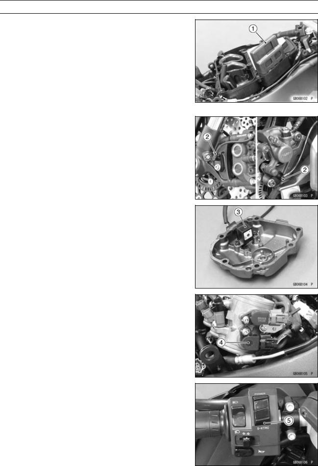
5. S-KTRC Button
The mode-switching signal is transmitted to the meter ECU by depressing the S-KTRC button (0.3 0.4 sec.).
1-16 GENERAL INFORMATION
Technical Information-Sport-Kawasaki TRaction Control System (S-KTRC)
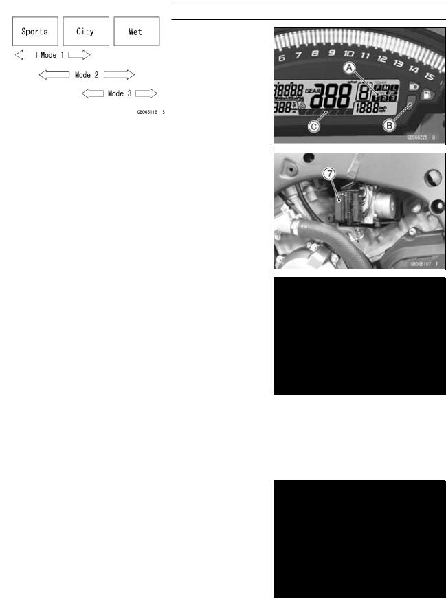
6. Multifunction Meter
The multifunction meter receives a mode-switching signal and displays the mode [A], and transmits it to the FI ECU by the CAN system.
When a failure occurs in the system, the multifunction meter displays the warning indication by blinking the warning indicator light (yellow LED) [B] and mode indicator symbol.
It also displays the S-KTRC operating conditions in the level indicator [C].
7. KIBS ECU
As for the KIBS equipped model, the front and rear wheel sensor signals are transmitted to the FI ECU via the KIBS ECU.
Mode-switching
Depress the S-KTRC button on the left handlebar switch to change the mode. The mode can be changed only when the throttle grip is closed completely.
The S-KTRC OFF can be selected only when the motorcycle is at a stop. Changing to mode 1 from S-KTRC OFF is possible while riding.
NOTE
○When changing the mode, stop the motorcycle.
○The mode is retained if the ignition switch is turned to OFF or if the battery is disconnected.
○When the ignition switch is turned to OFF, and then back to ON while S-KTRC is OFF, the system will automatically be set to mode 1.
○If the battery is disconnected and then reconnected while S-KTRC is OFF, the S-KTRC is set in mode 1.
Mode 1: S-KTRC least restrictive among the three modes. This makes lengthy drifts and wheelies possible when exiting tight corners.
Mode 2: There is more S-KTRC interaction compared to mode 1. This makes slight drifts possible when exiting tight corners.
Mode 3: S-KTRC intervenes to prevent the rear wheel from spinning whenever possible.

GENERAL INFORMATION 1-17
Technical Information-Power Mode
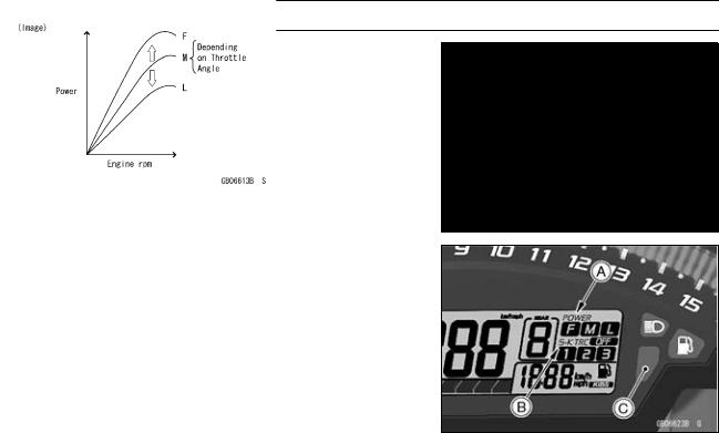
The rider can choose from three engine power modes to suit their preferences and road conditions. The FI ECU controls the engine power by adjusting fuel injection, air intake, and ignition timing. It enables three-mode selection: Full Power (Mode F), Middle Power (Mode M), and Low Power (Mode
L).
In addition, combining each mode with each S-KTRC setting allows the rider to have more choices to be able to interact with various conditions.
Power Mode Operation
To change the mode, close the throttle grip completely, and depress the power mode button [A] (0.3 0.4 sec.).
Power Mode Positions
NOTE
○The power mode setting is maintained when the ignition switch is turned OFF, or when the battery is disconnected.
1-18 GENERAL INFORMATION
Technical Information-Power Mode
Mode F: The highest engine power output is achieved. The rider can use the full power of the engine.
Mode M: The throttle response is less sharp compared to mode F. Depending on the throttle application, full power can be accessed temporarily.
Mode L: About 60% of the highest engine power output is achieved. The throttle response is mildest among the three modes.
The current mode selection is displayed on the power mode indicator [A] in the multifunction meter.
If a failure occurs with a FI related components such as a subthrottle or main throttle sensor, the warning indicator light (red LED) and FI warning symbol will go ON, and/or the S-KTRC indicator [B] and warning indicator light (yellow LED) [C] blink. The current mode cannot be changed at this time.
GENERAL INFORMATION 1-19
Technical Information-Kawasaki Intelligent anti-lock Brake System (KIBS/ZX1000K model only)
Overview
Kawasaki Intelligent anti-lock Brake System (KIBS) offers enhanced braking stability (ABS performance equivalent to the current model) to supersport models, which pitch more than most motorcycles and also offers high-precision front and rear brake pressure control (high-precision ABS) for sport riding.
Precise control of the ABS operation decreases kickback to the brake lever and brake pedal during braking compared to the conventional system.
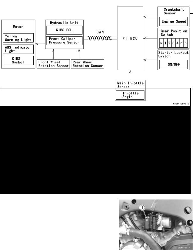
In addition to the front and rear wheel sensors in a conventional ABS, KIBS monitors a number of parameters: front caliper hydraulic pressure and information from the FI ECU (engine speed, throttle position, gear position, and clutch actuation).
KIBS uses an all-new BOSCH hydraulic unit which was designed specifically for motorcycle use. The new design is small and light weight (45% less volume and 800g lighter than current units). The unit is located close to the motorcycle’s center of gravity, behind the engine cylinder and above the sprocket cover.
System Components
1. KIBS ECU
With input from the front and rear wheel sensors and front caliper hydraulic pressure, the KIBS ECU analyzes various conditions on the motorcycle, and with additional information from the FI ECU (engine speed, throttle position, gear position, and clutch actuation) precisely controls the brake caliper hydraulic pressure. As a result, brake force is generated to suit conditions. If there is no engine information from the FI ECU, the KIBS is deactivated and the warning is displayed in the meter; however, the conventional ABS function is maintained.
2. Wheel Rotation Sensor
The wheel rotation sensor converts the front and rear wheel rotation speed to a pulse signal and transmits it to the KIBS ECU and FI ECU.
1-20 GENERAL INFORMATION
Technical Information-Kawasaki Intelligent anti-lock Brake System (KIBS/ZX1000K model only)
3. KIBS Hydraulic Unit
The KIBS hydraulic unit consists of the hydraulic unit and KIBS ECU and has the front caliper hydraulic pressure sensor built-in.
When receiving a signal from the KIBS ECU, the hydraulic unit increases or decreases the front and rear brake hydraulic pressure.
The front caliper hydraulic pressure sensor always monitors the front caliper hydraulic pressure and transmits the hydraulic pressure change to the KIBS ECU.
4. FI ECU
The FI ECU transmits information from the crankshaft sensor (engine speed), the main throttle sensor (throttle position), the gear position switch (gear position), and the starter lockout switch (ON/OFF) to the KIBS ECU by the CAN system.
5. Multifunction Meter
When a failure occurs in the system, the multifunction meter displays the warning indication by turning ON the warning indicator light (yellow LED) [A] and KIBS symbol [B].
Related Parts Locations
![]()
GENERAL INFORMATION 1-21
Technical Information-Kawasaki Intelligent anti-lock Brake System (KIBS/ZX1000K model only)
KIBS Control
1. ABS performance equivalent to the current model (enhanced braking stability)
By monitoring front caliper hydraulic pressure, KIBS regulates pressure increases reducing the tendency of the rear to lift. Before the ABS system fully reacts, KIBS system prevents the pressure from increasing too quickly thus suppressing rear lift. And after the ABS has decreased pressure to prevent wheel lock, it prevents a sudden pressure increase that could induce rear lift.
2. High-precision ABS to enhance front and rear braking performance
By monitoring front caliper hydraulic pressure, the KIBS system is able to regulate pressure changes precisely, so that slips are minimized resulting in smooth operation compared to the conventional ABS system.

1-22 GENERAL INFORMATION
Technical Information-Kawasaki Intelligent anti-lock Brake System (KIBS/ZX1000K model only)
3. Rear brake control enhancement during engine braking
By recognizing rear wheel slip due to engine brake force during aggressive throttle operation, and at high rpm or downshifting, the KIBS system prevents unnecessary ABS intervention to the rear wheel compared to the conventional ABS system.

GENERAL INFORMATION 1-23
Technical Information — Electronic Steering Damper (ESD/ZX1000JD/KD models)
1) Overview
This model has an Electronic Steering Damper (ESD) [A]. Unlike conventional manual adjustment method of Kawasaki, damping characteristics are adjusted by the electronic control unit.
2) Purpose
Designed to offer increased stability at high speed without interfering with light and nimble steering at low speed.
3) Advantages
Damping characteristics are properly adjusted by the electronic control unit based on primarily vehicle speed, and additionally acceleration/deceleration.
During public road riding, lighter damping characteristics are selected to preserve the natural nimble handling of this model.
During circuit riding, stiffer damping settings are chosen to enhance stability for better cornering. Like the public road riding settings, ESD provides the rider with moderate feedback while maintaining natural handling feel. (moderate and natural work fine here)
Electronic control is based on speed and acceleration, so at high speeds stability is enhanced.
4) Difference
Change the steering damper damping adjustment method from manual ( ZX1000JC/KC) to automatic (Stepper Motor).
|
Previous Models ( ZX1000JC/KC) |
New Models (ZX1000JD/KD) |
|

1-24 GENERAL INFORMATION
Technical Information — Electronic Steering Damper (ESD/ZX1000JD/KD models)
5) Related Parts
Meter [A]
Electronic Steering Damper (ESD) [B]

GENERAL INFORMATION 1-25
Technical Information — Electronic Steering Damper (ESD/ZX1000JD/KD models)
ESD ECU [A]
FI ECU [B]
Rear Wheel Rotation Sensor [A]
6) Meter
Added an indicator “ESD” warning symbol [A] in the instruments.
The yellow warning indicator light [B] and ESD warning symbol go on whenever there is a malfunction in the ESD system.
At this time, the ESD system maintains the last damping force setting.
7) Error Display
Only Meter Diagnosis
When both “ESD” warning symbol [A] and yellow warning indicator light [B] go on , the LCD displays service code [C] by push the upper button [D] at odometer indication (see Self-Diagnosis Procedures in the Self-Diagnosis System chapter).
|
Problems |
Service Code |
|
|
ESD actuator malfunction, wiring open or |
E2E |
|
|
short |
||
|
ESD ECU trouble (ESD ECU operation |
||
|
abnormal) |
E3b |
|
|
ESD ECU — FI ECU communication error |
||
|
Input signals for ESD trouble |
||
|
Low voltage |
||
|
ESD ECU communication error |
3C |

1-26 GENERAL INFORMATION
Unit Conversion Table
|
Prefixes for Units: |
Units of Length: |
|
Prefix |
Symbol |
Power |
||
|
mega |
M |
× 1 000 |
000 |
|
|
kilo |
k |
× |
1 000 |
|
|
centi |
c |
× |
0.01 |
|
|
milli |
m |
× |
0.001 |
|
|
micro |
µ |
× 0.000001 |
Units of Mass:
|
kg |
× |
2.205 |
= |
lb |
|
g |
× |
0.03527 |
= |
oz |
Units of Volume:
|
L |
× |
0.2642 |
= |
gal (US) |
|
L |
× |
0.2200 |
= |
gal (IMP) |
|
L |
× |
1.057 |
= |
qt (US) |
|
L |
× |
0.8799 |
= |
qt (IMP) |
|
L |
× |
2.113 |
= |
pint (US) |
|
L |
× |
1.816 |
= |
pint (IMP) |
|
mL |
× |
0.03381 |
= |
oz (US) |
|
mL |
× |
0.02816 |
= |
oz (IMP) |
|
mL |
× |
0.06102 |
= |
cu in. |
Units of Force:
|
N |
× |
0.1020 |
= |
kg |
|
N |
× |
0.2248 |
= |
lb |
|
kg |
× |
9.807 |
= |
N |
|
kg |
× |
2.205 |
= |
lb |
|
km |
× |
0.6214 |
= |
mile |
|
m |
× |
3.281 |
= |
ft |
|
mm |
× |
0.03937 |
= |
in. |
Units of Torque:
|
N·m |
× |
0.1020 |
= |
kgf·m |
|
N·m |
× |
0.7376 |
= |
ft·lb |
|
N·m |
× |
8.851 |
= |
in·lb |
|
kgf·m |
× |
9.807 |
= |
N·m |
|
kgf·m |
× |
7.233 |
= |
ft·lb |
|
kgf·m |
× |
86.80 |
= |
in·lb |
Units of Pressure:
|
kPa |
× |
0.01020 |
= |
kgf/cm² |
|
kPa |
× |
0.1450 |
= |
psi |
|
kPa |
× |
0.7501 |
= |
cmHg |
|
kgf/cm² |
× |
98.07 |
= |
kPa |
|
kgf/cm² |
× |
14.22 |
= |
psi |
|
cmHg |
× |
1.333 |
= |
kPa |
Units of Speed:
km/h × 0.6214 = mph
Units of Power:
|
kW |
× |
1.360 |
= |
PS |
|
kW |
× |
1.341 |
= |
HP |
|
PS |
× |
0.7355 |
= |
kW |
|
PS |
× |
0.9863 |
= |
HP |
Units of Temperature:

PERIODIC MAINTENANCE 2-1
Periodic Maintenance
Table of Contents
|
Periodic Maintenance Chart ……………………………………………………………………………………… |
2-3 |
||
|
Torque and Locking Agent………………………………………………………………………………………… |
2-6 |
2 |
|
|
Specifications |
2-12 |
||
|
Special Tools ………………………………………………………………………………………………………….. |
2-14 |
||
|
Periodic Maintenance Procedures……………………………………………………………………………… |
2-15 |
||
|
Fuel System (DFI)…………………………………………………………………………………………………. |
2-15 |
||
|
Throttle Control System Inspection……………………………………………………………………….. |
2-15 |
||
|
Engine Vacuum Synchronization Inspection…………………………………………………………… |
2-15 |
||
|
Idle Speed Inspection …………………………………………………………………………………………. |
2-19 |
||
|
Idle Speed Adjustment………………………………………………………………………………………… |
2-20 |
||
|
Fuel Hose Inspection (fuel leak, damage, installation condition) ……………………………….. |
2-20 |
||
|
Evaporative Emission Control System Inspection (CAL and SEA-B1 Models)…………….. |
2-21 |
||
|
Cooling System…………………………………………………………………………………………………….. |
2-22 |
||
|
Coolant Level Inspection……………………………………………………………………………………… |
2-22 |
||
|
Radiator Hose and Pipe Inspection (coolant leak, damage, installation condition) ………. |
2-22 |
||
|
Engine Top End ……………………………………………………………………………………………………. |
2-23 |
||
|
Valve Clearance Inspection …………………………………………………………………………………. |
2-23 |
||
|
Valve Clearance Adjustment………………………………………………………………………………… |
2-24 |
||
|
Air Suction System Damage Inspection…………………………………………………………………. |
2-26 |
||
|
Clutch………………………………………………………………………………………………………………….. |
2-27 |
||
|
Clutch Operation Inspection ………………………………………………………………………………… |
2-27 |
||
|
Wheels/Tires………………………………………………………………………………………………………… |
2-28 |
||
|
Tire Air Pressure Inspection…………………………………………………………………………………. |
2-28 |
||
|
Wheel/Tire Damage Inspection…………………………………………………………………………….. |
2-28 |
||
|
Tire Tread Wear Inspection …………………………………………………………………………………. |
2-29 |
||
|
Wheel Bearing Damage Inspection ………………………………………………………………………. |
2-29 |
||
|
Final Drive……………………………………………………………………………………………………………. |
2-30 |
||
|
Drive Chain Lubrication Condition Inspection …………………………………………………………. |
2-30 |
||
|
Drive Chain Slack Inspection ……………………………………………………………………………….. |
2-31 |
||
|
Drive Chain Slack Adjustment ……………………………………………………………………………… |
2-31 |
||
|
Wheel Alignment Inspection ………………………………………………………………………………… |
2-32 |
||
|
Drive Chain Wear Inspection ……………………………………………………………………………….. |
2-32 |
||
|
Chain Guide Wear Inspection ………………………………………………………………………………. |
2-33 |
||
|
Brakes…………………………………………………………………………………………………………………. |
2-34 |
||
|
Brake Fluid Leak (Brake Hose and Pipe) Inspection ……………………………………………….. |
2-34 |
||
|
Brake Hose and Pipe Damage and Installation Condition Inspection…………………………. |
2-35 |
||
|
Brake Fluid Level Inspection………………………………………………………………………………… |
2-35 |
||
|
Brake Pad Wear Inspection …………………………………………………………………………………. |
2-36 |
||
|
Brake Operation Inspection …………………………………………………………………………………. |
2-36 |
||
|
Brake Light Switch Operation Inspection ……………………………………………………………….. |
2-36 |
||
|
Suspension………………………………………………………………………………………………………….. |
2-37 |
||
|
Front Forks/Rear Shock Absorber Operation Inspection ………………………………………….. |
2-37 |
||
|
Front Fork Oil Leak Inspection……………………………………………………………………………… |
2-38 |
||
|
Rear Shock Absorber Oil Leak Inspection ……………………………………………………………… |
2-38 |
||
|
Rocker Arm Operation Inspection…………………………………………………………………………. |
2-38 |
||
|
Tie-Rod Operation Inspection ………………………………………………………………………………. |
2-38 |
||
|
Steering ………………………………………………………………………………………………………………. |
2-39 |
||
|
Steering Play Inspection ……………………………………………………………………………………… |
2-39 |
||
|
Steering Play Adjustment…………………………………………………………………………………….. |
2-39 |
||
|
Steering Stem Bearing Lubrication ……………………………………………………………………….. |
2-40 |

2-2 PERIODIC MAINTENANCE
|
Steering Damper Oil Leak Inspection ……………………………………………………………………. |
2-41 |
|
Electrical System ………………………………………………………………………………………………….. |
2-42 |
|
Lights and Switches Operation Inspection……………………………………………………………… |
2-42 |
|
Headlight Aiming Inspection ………………………………………………………………………………… |
2-44 |
|
Headlight Aiming Adjustment……………………………………………………………………………….. |
2-44 |
|
Sidestand Switch Operation Inspection …………………………………………………………………. |
2-45 |
|
Engine Stop Switch Operation Inspection………………………………………………………………. |
2-46 |
|
Others…………………………………………………………………………………………………………………. |
2-47 |
|
Chassis Parts Lubrication …………………………………………………………………………………… |
2-47 |
|
Bolts, Nuts and Fasteners Tightness Inspection……………………………………………………… |
2-48 |
|
Replacement Parts ……………………………………………………………………………………………….. |
2-50 |
|
Air Cleaner Element Replacement………………………………………………………………………… |
2-50 |
|
Fuel Hose Replacement ……………………………………………………………………………………… |
2-50 |
|
Coolant Change …………………………………………………………………………………………………. |
2-54 |
|
Radiator Hose and O-ring Replacement………………………………………………………………… |
2-56 |
|
Engine Oil Change……………………………………………………………………………………………… |
2-57 |
|
Oil Filter Replacement ………………………………………………………………………………………… |
2-58 |
|
Brake Hose and Pipe Replacement………………………………………………………………………. |
2-59 |
|
Brake Fluid Change ……………………………………………………………………………………………. |
2-62 |
|
Master Cylinder Rubber Parts Replacement ………………………………………………………….. |
2-63 |
|
Caliper Rubber Parts Replacement ………………………………………………………………………. |
2-65 |
|
Spark Plug Replacement …………………………………………………………………………………….. |
2-69 |

PERIODIC MAINTENANCE 2-3
Periodic Maintenance Chart
The scheduled maintenance must be done in accordance with this chart to keep the motorcycle in good running condition. The initial maintenance is vitally important and must not be neglected.
Periodic Inspection
|
FREQUENCY |
Whichever |
* ODOMETER READING |
||||||||||||
|
comes |
× 1 000 km |
See |
||||||||||||
|
first |
(× 1 000 mile) |
|||||||||||||
|
Page |
||||||||||||||
|
1 |
6 |
12 |
18 |
24 |
30 |
36 |
||||||||
|
ITEM |
Every |
(0.6) |
(3.75) |
(7.5) |
(11.25) |
(15) |
(18.75) |
(22.5) |
||||||
|
Fuel System |
||||||||||||||
|
Throttle control system |
year |
• |
• |
• |
• |
2-15 |
||||||||
|
(play, smooth return, no |
||||||||||||||
|
drag) — inspect |
||||||||||||||
|
Engine vacuum |
• |
• |
• |
2-15 |
||||||||||
|
synchronization — inspect |
||||||||||||||
|
Idle speed — inspect |
• |
• |
• |
• |
2-19 |
|||||||||
|
Fuel leak (fuel hose and |
year |
• |
• |
• |
• |
2-20 |
||||||||
|
pipe) — inspect |
||||||||||||||
|
Fuel hose and pipe damage |
year |
• |
• |
• |
• |
2-20 |
||||||||
|
— inspect |
||||||||||||||
|
Fuel hose and pipe |
year |
• |
• |
• |
• |
2-20 |
||||||||
|
installation condition — |
||||||||||||||
|
inspect |
||||||||||||||
|
Evaporative emission |
||||||||||||||
|
control system function — |
• |
• |
• |
• |
• |
• |
• |
2-21 |
||||||
|
inspect (CAL and SEA-B1 |
||||||||||||||
|
Models) |
||||||||||||||
|
Cooling System |
||||||||||||||
|
Coolant level — inspect |
• |
• |
• |
• |
2-22 |
|||||||||
|
Coolant leak (water hose |
year |
• |
• |
• |
• |
2-22 |
||||||||
|
and pipe) — inspect |
||||||||||||||
|
Water hose damage — |
year |
• |
• |
• |
• |
2-22 |
||||||||
|
inspect |
||||||||||||||
|
Water hose installation |
year |
• |
• |
• |
• |
2-22 |
||||||||
|
condition — inspect |
||||||||||||||
|
Engine Top End |
||||||||||||||
|
Valve clearance — inspect |
• |
2-23 |
||||||||||||
|
Air suction system damage |
• |
• |
• |
2-26 |
||||||||||
|
— inspect |
||||||||||||||
|
Clutch |
||||||||||||||
|
Clutch operation |
• |
• |
• |
• |
2-27 |
|||||||||
|
(play, disengagement, |
||||||||||||||
|
engagement) — inspect |
||||||||||||||
|
Wheels and Tires |
||||||||||||||
|
Tire air pressure — inspect |
year |
• |
• |
• |
2-28 |
|||||||||
|
Wheel/tire damage — inspect |
• |
• |
• |
2-28 |
||||||||||
|
Tire tread wear, abnormal |
• |
• |
• |
2-29 |
||||||||||
|
wear — inspect |
||||||||||||||

2-4 PERIODIC MAINTENANCE
Periodic Maintenance Chart
|
FREQUENCY |
Whichever |
* ODOMETER READING |
|||||||||||
|
comes |
× 1 000 km |
See |
|||||||||||
|
first |
(× 1 000 mile) |
||||||||||||
|
Page |
|||||||||||||
|
1 |
6 |
12 |
18 |
24 |
30 |
36 |
|||||||
|
ITEM |
Every |
(0.6) |
(3.75) |
(7.5) |
(11.25) |
(15) |
(18.75) |
(22.5) |
|||||
|
Wheel bearing damage — |
year |
• |
• |
• |
2-29 |
||||||||
|
inspect |
|||||||||||||
|
Final Drive |
|||||||||||||
|
Drive chain lubrication |
Every 600 km (400 mile) |
2-30 |
|||||||||||
|
condition — inspect # |
|||||||||||||
|
Drive chain slack — inspect # |
Every 1 000 km (600 mile) |
2-31 |
|||||||||||
|
Drive chain wear — inspect # |
• |
• |
• |
2-32 |
|||||||||
|
Chain guide wear — inspect |
• |
• |
• |
2-33 |
|||||||||
|
Brakes |
|||||||||||||
|
Brake fluid leak (brake hose |
year |
• |
• |
• |
• |
• |
• |
• |
2-34 |
||||
|
and pipe) — inspect |
|||||||||||||
|
Brake hose and pipe |
year |
• |
• |
• |
• |
• |
• |
• |
2-35 |
||||
|
damage — inspect |
|||||||||||||
|
Brake hose installation |
year |
• |
• |
• |
• |
• |
• |
• |
2-35 |
||||
|
condition — inspect |
|||||||||||||
|
Brake fluid level — inspect |
6 |
• |
• |
• |
• |
• |
• |
• |
2-35 |
||||
|
months |
|||||||||||||
|
Brake pad wear — inspect # |
• |
• |
• |
• |
• |
• |
2-36 |
||||||
|
Brake operation |
year |
• |
• |
• |
• |
• |
• |
• |
2-36 |
||||
|
(effectiveness, play, no |
|||||||||||||
|
drag) — inspect |
|||||||||||||
|
Brake light switch operation |
• |
• |
• |
• |
• |
• |
• |
2-36 |
|||||
|
— inspect |
|||||||||||||
|
Suspension |
|||||||||||||
|
Front forks/rear shock |
|||||||||||||
|
absorber operation |
• |
• |
• |
2-37 |
|||||||||
|
(damping and smooth |
|||||||||||||
|
stroke) — inspect |
|||||||||||||
|
Front forks/rear shock |
year |
• |
• |
• |
2-38 |
||||||||
|
absorber oil leak — inspect |
|||||||||||||
|
Rocker arms operation — |
• |
• |
• |
2-38 |
|||||||||
|
inspect |
|||||||||||||
|
Tie-rod operation — inspect |
• |
• |
• |
2-38 |
|||||||||
|
Steering |
|||||||||||||
|
Steering play — inspect |
year |
• |
• |
• |
• |
2-39 |
|||||||
|
Steering stem bearings — |
2 years |
• |
2-40 |
||||||||||
|
lubricate |
|||||||||||||
|
Steering damper oil leak — |
• |
• |
• |
• |
• |
• |
2-41 |
||||||
|
inspect |
|||||||||||||
|
Electrical System |
|||||||||||||
|
Lights and switches |
year |
• |
• |
• |
2-42 |
||||||||
|
operation — inspect |
|||||||||||||
|
Headlight aiming — inspect |
year |
• |
• |
• |
2-44 |
||||||||
![]()
|
PERIODIC MAINTENANCE 2-5 |
||||||||||||||
|
Periodic Maintenance Chart |
||||||||||||||
|
FREQUENCY |
Whichever |
* ODOMETER READING |
||||||||||||
|
comes |
× 1 000 km |
See |
||||||||||||
|
first |
(× 1 000 mile) |
|||||||||||||
|
Page |
||||||||||||||
|
1 |
6 |
12 |
18 |
24 |
30 |
36 |
||||||||
|
ITEM |
Every |
(0.6) |
(3.75) |
(7.5) |
(11.25) |
(15) |
(18.75) |
(22.5) |
||||||
|
Sidestand switch operation |
year |
• |
• |
• |
2-45 |
|||||||||
|
— inspect |
||||||||||||||
|
Engine stop switch |
year |
• |
• |
• |
2-46 |
|||||||||
|
operation — inspect |
||||||||||||||
|
Others |
||||||||||||||
|
Chassis parts — lubricate |
year |
• |
• |
• |
2-47 |
|||||||||
|
Bolts and nuts tightness — |
• |
• |
• |
• |
2-48 |
|||||||||
|
inspect |
||||||||||||||
#: Service more frequently when operating in severe conditions; dusty, wet, muddy, high speed or frequent starting/stopping.
*: For higher odometer readings, repeat at the frequency interval established here.
Periodic Replacement Parts
|
FREQUENCY |
Whichever |
* ODOMETER READING |
||||||||||
|
comes |
× 1 000 km |
See |
||||||||||
|
first |
(× 1 000 mile) |
|||||||||||
|
Page |
||||||||||||
|
1 |
12 |
24 |
36 |
48 |
||||||||
|
ITEM |
Every |
(0.6) |
(7.5) |
(15) |
(22.5) |
(30) |
||||||
|
Air cleaner element — replace # |
Every 18 000 km (12 000 mile) |
2-50 |
||||||||||
|
Fuel hose — replace |
5 years |
2-50 |
||||||||||
|
Coolant — change |
3 years |
• |
2-54 |
|||||||||
|
Radiator hose and O-ring — replace |
3 years |
• |
2-56 |
|||||||||
|
Engine oil — change # |
year |
• |
• |
• |
• |
• |
2-57 |
|||||
|
Oil filter — replace |
year |
• |
• |
• |
• |
• |
2-58 |
|||||
|
Brake hose — replace |
4 years |
• |
2-59 |
|||||||||
|
Brake fluid — change |
2 years |
• |
• |
2-62 |
||||||||
|
Rubber parts of master cylinder and caliper — |
4 years |
• |
2-63, |
|||||||||
|
replace |
2-65 |
|||||||||||
|
Spark plug — replace |
• |
• |
• |
• |
2-69 |
#: Service more frequently when operating in severe conditions; dusty, wet, muddy, high speed or frequent starting/stopping.
*: For higher odometer readings, repeat at the frequency interval established here.

2-6 PERIODIC MAINTENANCE
Torque and Locking Agent
The following tables list the tightening torque for the major fasteners requiring use of a non-permanent locking agent or silicone sealant etc.
Letters used in the “Remarks” column mean:
AL: Tighten the two clamp bolts alternately two times to ensure even tightening torque. G: Apply grease.
L: Apply a non-permanent locking agent. Lh: Left-hand Threads
MO: Apply molybdenum disulfide oil solution.
(mixture of the engine oil and molybdenum disulfide grease in a weight ratio 10:1)
R:Replacement Parts
S:Follow the specified tightening sequence. Si: Apply silicone grease (ex. PBC grease).
SS: Apply silicone sealant.
|
Fastener |
Torque |
Remarks |
|||
|
N·m |
kgf·m |
ft·lb |
|||
|
Fuel System (DFI) |
|||||
|
Air Cleaner Housing Assembly Screws |
1.1 |
0.11 |
10 in·lb |
||
|
Air Cleaner Housing Clamp Bolts |
2.0 |
0.20 |
18 in·lb |
||
|
Air Cleaner Housing Duct Screws |
1.1 |
0.11 |
10 in·lb |
||
|
Air Intake Duct Assembly Screws |
1.5 |
13 in·lb |
|||
|
0.15 |
|||||
|
Air Intake Solenoid Valve Nut |
7.0 |
0.71 |
62 in·lb |
||
|
Intake Air Temperature Sensor Screw |
0.8 |
0.08 |
7.1 in·lb |
||
|
Bracket Screw |
3.4 |
0.35 |
30 in·lb |
||
|
Delivery Pipe Assy Mounting Screws |
3.43 |
0.35 |
30 in·lb |
||
|
Fitting Retainer Screws |
2.06 |
0.21 |
18 in·lb |
||
|
Fitting Screws |
3.43 |
0.35 |
30 in·lb |
||
|
Idle Speed Control Valve Actuator Retainer Screws |
2.06 |
0.21 |
18 in·lb |
||
|
Nozzle Assy Mounting Bolts |
4.9 |
0.50 |
43 in·lb |
S |
|
|
Throttle Body Assy Holder Clamp Bolts |
2.0 |
0.20 |
18 in·lb |
||
|
Crankshaft Sensor Bolts |
5.9 |
0.60 |
52 in·lb |
L |
|
|
Fuel Pump Bolts |
9.8 |
1.0 |
87 in·lb |
L, S |
|
|
Gear Position Switch Screws |
2.9 |
0.30 |
26 in·lb |
L |
|
|
Oxygen Sensor (Equipped Models) |
25 |
2.5 |
18 |
||
|
Water Temperature Sensor |
12 |
1.2 |
106 in·lb |
||
|
Exhaust Butterfly Valve Actuator Mounting Screws |
1.2 |
0.12 |
11 in·lb |
||
|
Exhaust Butterfly Valve Actuator Pulley Bolt |
4.9 |
0.50 |
43 in·lb |
||
|
Cooling System |
|||||
|
Water Hose Clamp Screws |
27 in·lb |
||||
|
3.0 |
0.31 |
||||
|
Water Pipe Mounting Bolt |
9.8 |
1.0 |
87 in·lb |
L |
|
|
Water Pump Cover Bolts |
9.8 |
1.0 |
87 in·lb |
L (2) |
|
|
Coolant Drain Bolt (Water Pump) |
87 in·lb |
||||
|
9.8 |
1.0 |
||||
|
Impeller Bolt |
9.8 |
1.0 |
87 in·lb |
||
|
Water Temperature Sensor |
12 |
1.2 |
106 in·lb |
||
|
Coolant By-pass Fitting Bolt |
8.8 |
0.90 |
78 in·lb |
L |
|
|
Thermostat Housing Mounting Bolts |
9.8 |
1.0 |
87 in·lb |
||
|
Thermostat Cap Bolts |
5.9 |
0.60 |
52 in·lb |

PERIODIC MAINTENANCE 2-7
Torque and Locking Agent
|
Fastener |
Torque |
Remarks |
|||
|
N·m |
kgf·m |
ft·lb |
|||
|
Oil Cooler Mounting Bolts |
12 |
1.2 |
106 in·lb |
L, S |
|
|
Water Hose Fitting Bolts |
9.8 |
1.0 |
87 in·lb |
||
|
Coolant Drain Bolt (Cylinder) |
9.8 |
1.0 |
87 in·lb |
||
|
Water Passage Plugs |
20 |
2.0 |
15 |
L |
|
|
Engine Top End |
|||||
|
Air Suction Valve Cover Bolts |
9.8 |
1.0 |
87 in·lb |
L |
|
|
Camshaft Cap Bolts |
12 |
1.2 |
106 in·lb |
S |
|
|
Camshaft Chain Tensioner Cap Bolt |
20 |
2.0 |
15 |
||
|
Camshaft Chain Tensioner Mounting Bolts |
9.8 |
1.0 |
87 in·lb |
||
|
Camshaft Sprocket Bolts |
15 |
1.5 |
11 |
L |
|
|
Coolant Drain Bolt (Cylinder) |
9.8 |
87 in·lb |
|||
|
1.0 |
|||||
|
Cylinder Head Bolts (M10) |
45 |
4.6 |
33 |
MO, S |
|
|
Cylinder Head Bolts (M6) |
12 |
1.2 |
106 in·lb |
S |
|
|
Cylinder Head Cover Bolts |
9.8 |
1.0 |
87 in·lb |
S |
|
|
Cylinder Head Cover Plug |
15 |
1.5 |
11 |
L |
|
|
Front Camshaft Chain Guide Bolt (Lower) |
12 |
1.2 |
106 in·lb |
||
|
Front Camshaft Chain Guide Bolt (Upper) |
|||||
|
25 |
2.5 |
18 |
|||
|
Spark Plugs |
13 |
1.3 |
115 in·lb |
||
|
Throttle Body Assy Holder Bolts |
9.8 |
1.0 |
87 in·lb |
S |
|
|
Upper Camshaft Chain Guide Bolts |
12 |
1.2 |
106 in·lb |
S |
|
|
Water Passage Plugs |
20 |
2.0 |
15 |
L |
|
|
Muffler Body Mounting Bolt |
25 |
2.5 |
18 |
||
|
Premuffler Chamber Mounting Bolt |
34 |
3.5 |
25 |
||
|
Clutch |
|||||
|
Clutch Lever Clamp Bolts |
7.8 |
0.80 |
69 in·lb |
S |
|
|
Clutch Cover Bolts |
9.8 |
1.0 |
87 in·lb |
S |
|
|
Oil Filler Plug |
– |
– |
– |
Hand-tighten |
|
|
Clutch Cover Plate Bolts |
9.8 |
1.0 |
87 in·lb |
L |
|
|
Clutch Spring Bolts |
11 |
1.1 |
97 in·lb |
||
|
Sub Clutch Hub Bolts |
25 |
2.5 |
18 |
L |
|
|
Clutch Hub Nut |
130 |
13.3 |
96 |
R |
|
|
Engine Lubrication System |
|||||
|
Oil Cooler Mounting Bolts |
12 |
1.2 |
106 in·lb |
L, S |
|
|
Oil Pressure Switch |
15 |
1.5 |
11 |
SS |
|
|
Oil Pressure Switch Terminal Bolt |
1.5 |
0.15 |
13 in·lb |
G |
|
|
Oil Pump Drive Chain Guide Bolt |
9.8 |
1.0 |
87 in·lb |
L |
|
|
Oil Pump Drive Gear Bolt |
9.8 |
1.0 |
87 in·lb |
L, Lh |
|
|
Oil Passage Plug (Taper) |
20 |
2.0 |
15 |
L |
|
|
Oil Pipe Holder Bolt |
9.8 |
1.0 |
87 in·lb |
L |
|
|
Oil Pressure Relief Valve |
15 |
1.5 |
11 |
L |
|
|
Oil Filter |
17 |
1.7 |
13 |
G, R |
|
|
Oil Filter Holder Bolt |
35 |
3.6 |
26 |
L |
|
|
Oil Pan Bolts |
9.8 |
1.0 |
87 in·lb |
S |

2-8 PERIODIC MAINTENANCE
Torque and Locking Agent
|
Fastener |
Torque |
Remarks |
|||
|
N·m |
kgf·m |
ft·lb |
|||
|
Engine Oil Drain Bolt |
29 |
3.0 |
21 |
||
|
Engine Removal/Installation |
|||||
|
Adjusting Collar Locknut |
49 |
5.0 |
36 |
S |
|
|
Left Front Engine Mounting Bolt |
44 |
4.5 |
32 |
S |
|
|
Lower Engine Mounting Bolt |
87 in·lb |
S |
|||
|
9.8 |
1.0 |
||||
|
Lower Engine Mounting Nut |
44 |
4.5 |
32 |
R, S |
|
|
Middle Engine Mounting Bolt |
9.8 |
1.0 |
87 in·lb |
S |
|
|
Middle Engine Mounting Nut |
44 |
4.5 |
32 |
R, S |
|
|
Right Front Engine Mounting Bolt |
44 |
4.5 |
32 |
S |
|
|
Crankshaft/Transmission |
|||||
|
Balanser Shaft Clamp Bolt |
9.8 |
87 in·lb |
|||
|
1.0 |
|||||
|
Balanser Shaft Clamp Lever Bolt |
25 |
2.5 |
18 |
L |
|
|
Bearing Holder Bolts |
15 |
1.5 |
11 |
L |
|
|
Breather Hole Plug |
15 |
1.5 |
11 |
L |
|
|
Breather Plate Bolts |
9.8 |
1.0 |
87 in·lb |
L |
|
|
Connecting Rod Big End Nuts |
see the |
MO, R |
|||
|
text |
|||||
|
Coolant Drain Bolt (Cylinder) |
9.8 |
1.0 |
87 in·lb |
||
|
Crankcase Bolt (M6, L = 60) |
12 |
1.2 |
106 in·lb |
||
|
Crankcase Bolt (M7, L = 45) |
|||||
|
20 |
2.0 |
15 |
|||
|
Crankcase Bolts (M6, L = 40) |
12 |
1.2 |
106 in·lb |
||
|
Crankcase Bolts (M6, L = 45) |
12 |
1.2 |
106 in·lb |
||
|
Crankcase Bolts (M7, L = 50) |
20 |
2.0 |
15 |
||
|
Crankcase Bolts (M8, L = 63) |
27 |
2.8 |
20 |
||
|
Crankcase Bolts (M9, L = 100) |
45 |
4.6 |
33 |
MO, S |
|
|
Crankcase Bolts (M9, L = 113) |
45 |
4.6 |
33 |
MO, S |
|
|
Oil Jet Nozzle (M6) |
4.9 |
0.50 |
43 in·lb |
||
|
Oil Jet Nozzle (M8) |
8.0 |
0.82 |
71 in·lb |
||
|
Oil Jet Nozzle (M10) |
15 |
1.5 |
11 |
||
|
Oil Jet Nozzles (M5) |
2.9 |
0.30 |
26 in·lb |
||
|
Oil Passage Plugs (Taper) |
20 |
2.0 |
15 |
L |
|
|
Oil Pressure Switch |
15 |
1.5 |
11 |
SS |
|
|
Oil Pressure Switch Terminal Bolt |
1.5 |
0.15 |
13 in·lb |
G |
|
|
Plate Bolts |
4.9 |
0.50 |
43 in·lb |
L |
|
|
Torque Limiter Cover Bolts |
9.8 |
1.0 |
87 in·lb |
||
|
Engine Sprocket Nut |
145 |
14.8 |
107 |
MO |
|
|
Gear Position Switch Screws |
2.9 |
0.30 |
26 in·lb |
L |
|
|
Gear Positioning Lever Bolt |
12 |
1.2 |
106 in·lb |
||
|
Shift Drum Cam Holder Bolt |
24 |
2.4 |
18 |
L |
|
|
Shift Pedal Mounting Bolt |
25 |
2.5 |
18 |
L |
|
|
Shift Ratchet Assembly Holder Bolts |
15 |
1.5 |
11 |
L |
|
|
Shift Shaft Return Spring Pin |
29 |
3.0 |
21 |
L |
|
|
Transmission Case Bearing Holder Bolts (L = 15) |
4.9 |
0.50 |
43 in·lb |
L |

PERIODIC MAINTENANCE 2-9
Torque and Locking Agent
|
Fastener |
Torque |
Remarks |
|||
|
N·m |
kgf·m |
ft·lb |
|||
|
Transmission Case Bearing Holder Bolts (L = 14) |
4.9 |
0.50 |
43 in·lb |
L |
|
|
Transmission Case Bolts |
20 |
2.0 |
15 |
||
|
Torque Limiter Shaft Plug |
25 |
2.5 |
18 |
L |
|
|
Starter Clutch Shaft Holder Bolt |
9.8 |
1.0 |
87 in·lb |
L |
|
|
Starter Clutch Shaft Bolt |
20 |
2.0 |
15 |
L |
|
|
Wheels/Tires |
|||||
|
Front Axle Clamp Bolts |
20 |
2.0 |
15 |
AL |
|
|
Front Axle Nut |
127 |
13.0 |
94 |
||
|
Rear Axle Nut |
127 |
13.0 |
94 |
||
|
Final Drive |
|||||
|
Engine Sprocket Cover Bolts |
9.8 |
87 in·lb |
|||
|
1.0 |
|||||
|
Engine Sprocket Nut |
145 |
14.8 |
107 |
MO |
|
|
Rear Axle Nut |
127 |
13.0 |
94 |
||
|
Rear Sprocket Nuts |
59 |
6.0 |
44 |
R |
|
|
Brakes |
|||||
|
Bleed Valves |
7.8 |
0.80 |
69 in·lb |
||
|
Brake Hose Banjo Bolts |
25 |
2.5 |
18 |
||
|
Brake Lever Pivot Bolt |
1.2 |
0.12 |
11 in·lb |
Si |
|
|
Brake Lever Pivot Bolt Locknut |
5.9 |
0.60 |
52 in·lb |
||
|
Brake Disc Mounting Bolts |
27 |
2.8 |
20 |
L |
|
|
Front Brake Light Switch Screw |
1.2 |
0.12 |
11 in·lb |
||
|
Front Brake Pad Pins |
15 |
1.5 |
11 |
||
|
Front Brake Reservoir Cap Stopper Screw |
1.2 |
0.12 |
11 in·lb |
||
|
Front Caliper Assembly Bolts |
22 |
2.2 |
16 |
||
|
Front Caliper Mounting Bolts |
34 |
3.5 |
25 |
||
|
Front Master Cylinder Bleed Valve |
5.4 |
0.55 |
48 in·lb |
||
|
Front Master Cylinder Clamp Bolts |
11 |
1.1 |
97 in·lb |
S |
|
|
Brake Pedal Mounting Bolt |
8.8 |
0.90 |
78 in·lb |
L |
|
|
Rear Brake Pad Pin |
17 |
1.7 |
13 |
||
|
Rear Brake Pad Pin Plug |
2.5 |
0.25 |
22 in·lb |
||
|
Rear Caliper Pin Bolt |
27 |
2.8 |
20 |
Si |
|
|
Rear Master Cylinder Mounting Bolts |
25 |
2.5 |
18 |
||
|
Rear Master Cylinder Push Rod Locknut |
17 |
1.7 |
13 |
||
|
Brake Pipe Joint Nuts |
18 |
1.8 |
13 |
||
|
Suspension |
|||||
|
Front Fork Clamp Bolts (Upper) |
20 |
2.0 |
15 |
||
|
Front Fork Clamp Bolts (Lower) |
23 |
2.3 |
17 |
AL |
|
|
Front Fork Top Plugs |
35 |
3.6 |
26 |
||
|
Piston Rod Guide Case |
90 |
9.2 |
66 |
||
|
Front Axle Clamp Bolts |
20 |
2.0 |
15 |
AL |
|
|
Rear Shock Absorber Nut (Lower) |
34 |
3.5 |
25 |
R |
|
|
Rear Shock Absorber Bracket Nut |
59 |
6.0 |
44 |
R |
|
|
Swingarm Pivot Adjusting Collar Locknut |
98 |
10.0 |
72 |

2-10 PERIODIC MAINTENANCE
Torque and Locking Agent
|
Fastener |
Torque |
Remarks |
|||
|
N·m |
kgf·m |
ft·lb |
|||
|
Swingarm Pivot Shaft |
20 |
2.0 |
15 |
||
|
Swingarm Pivot Shaft Nut |
108 |
11.0 |
80 |
||
|
Tie-Rod Nuts |
34 |
3.5 |
25 |
R |
|
|
Rocker Arm Nut |
34 |
3.5 |
25 |
R |
|
|
Rear Shock Absorber Nut (Upper) |
34 |
3.5 |
25 |
R |
|
|
Steering |
|||||
|
Steering Stem Head Nut |
78 |
8.0 |
58 |
||
|
Steering Stem Nut |
20 |
2.0 |
15 |
||
|
Left Switch Housing Screws |
3.5 |
0.36 |
31 in·lb |
||
|
Right Switch Housing Screws |
3.5 |
0.36 |
31 in·lb |
||
|
Front Fork Clamp Bolts (Upper) |
20 |
15 |
|||
|
2.0 |
|||||
|
Handlebar Clamp Bolts |
25 |
2.5 |
18 |
||
|
Handlebar Positioning Bolts |
9.8 |
1.0 |
87 in·lb |
L |
|
|
Throttle Case Screws |
3.5 |
0.36 |
31 in·lb |
||
|
Steering Damper Mounting Bolts |
11 |
1.1 |
97 in·lb |
L |
|
|
Front Fork Clamp Bolts (Lower) |
23 |
2.3 |
17 |
AL |
|
|
Frame |
|||||
|
Front Fender Mounting Bolts |
3.9 |
0.40 |
35 in·lb |
L |
|
|
Front Footpeg Bracket Bolts |
25 |
2.5 |
18 |
||
|
Rear Footpeg Bracket Bolts |
25 |
2.5 |
18 |
||
|
Rear Frame Front Bolts |
44 |
4.5 |
32 |
L |
|
|
Rear Frame Rear Bolts |
25 |
2.5 |
18 |
L |
|
|
Sidestand Bolt |
44 |
4.5 |
32 |
S |
|
|
Sidestand Bracket Bolts |
49 |
5.0 |
36 |
L |
|
|
Sidestand Nut |
29 |
3.0 |
21 |
R, S |
|
|
Sidestand Switch Bolt |
8.8 |
0.90 |
78 in·lb |
L |
|
|
Windshield Mounting Bolts |
1.2 |
0.12 |
11 in·lb |
||
|
Electrical System |
|||||
|
License Plate Light Mounting Screws |
11 in·lb |
||||
|
1.2 |
0.12 |
||||
|
Meter Unit Mounting Screws |
1.2 |
0.12 |
11 in·lb |
||
|
Tail/Brake Light Mounting Screws |
1.2 |
0.12 |
11 in·lb |
||
|
Rear Turn Signal Light Lens Screws |
1.0 |
0.10 |
8.9 in·lb |
||
|
Alternator Cover Bolts |
9.8 |
1.0 |
87 in·lb |
||
|
Alternator Lead Holding Plate Bolt |
9.8 |
1.0 |
87 in·lb |
L |
|
|
Alternator Rotor Bolt |
155 |
15.8 |
114 |
||
|
Crankshaft Sensor Bolts |
5.9 |
0.60 |
52 in·lb |
L |
|
|
Crankshaft Sensor Cover Bolts |
9.8 |
1.0 |
87 in·lb |
||
|
Fuel Pump Bolts |
9.8 |
1.0 |
87 in·lb |
L, S |
|
|
Gear Position Switch Screws |
2.9 |
0.30 |
26 in·lb |
L |
|
|
Oil Pressure Switch |
15 |
1.5 |
11 |
SS |
|
|
Oil Pressure Switch Terminal Bolt |
1.5 |
0.15 |
13 in·lb |
G |
|
|
Oxygen Sensor (Equipped Models) |
25 |
2.5 |
18 |
||
|
Spark Plugs |
13 |
1.3 |
115 in·lb |

PERIODIC MAINTENANCE 2-11
Torque and Locking Agent
|
Fastener |
Torque |
Remarks |
|||
|
N·m |
kgf·m |
ft·lb |
|||
|
Stator Coil Bolts |
12 |
1.2 |
106 in·lb |
L |
|
|
Timing Rotor Bolt |
39 |
4.0 |
29 |
||
|
Water Temperature Sensor |
12 |
1.2 |
106 in·lb |
||
|
Brush Holder Screw |
3.8 |
0.39 |
34 in·lb |
||
|
Engine Ground Terminal Bolt |
9.8 |
87 in·lb |
|||
|
1.0 |
|||||
|
Front Brake Light Switch Screw |
1.2 |
0.12 |
11 in·lb |
||
|
Left Switch Housing Screws |
3.5 |
0.36 |
31 in·lb |
||
|
Right Switch Housing Screws |
3.5 |
0.36 |
31 in·lb |
||
|
Sidestand Switch Bolt |
8.8 |
0.90 |
78 in·lb |
L |
|
|
Starter Motor Cable Terminal Nut |
5.9 |
0.60 |
52 in·lb |
||
|
Starter Motor Mounting Bolts |
9.8 |
1.0 |
87 in·lb |
L |
|
|
Starter Motor Terminal Locknut |
11 |
1.1 |
97 in·lb |
||
|
Starter Motor Through Bolts |
5.0 |
0.51 |
44 in·lb |
The table below, relating tightening torque to thread diameter, lists the basic torque for the bolts and nuts. Use this table for only the bolts and nuts which do not require a specific torque value. All of the values are for use with dry solvent-cleaned threads.
Basic Torque for General Fasteners
|
Threads Diameter |
Torque |
||||||||
|
(mm) |
N·m |
kgf·m |
ft·lb |
||||||
|
5 |
3.4 |
4.9 |
0.35 |
0.50 |
30 |
43 in·lb |
|||
|
6 |
5.9 |
7.8 |
0.60 |
0.80 |
52 |
69 in·lb |
|||
|
8 |
14 |
19 |
1.4 |
1.9 |
10 |
13.5 |
|||
|
10 |
25 |
34 |
2.6 |
3.5 |
19 |
25 |
|||
|
12 |
44 |
61 |
4.5 |
6.2 |
33 |
45 |
|||
|
14 |
73 |
98 |
7.4 |
10.0 |
54 |
72 |
|||
|
16 |
115 |
155 |
11.5 |
16.0 |
83 |
115 |
|||
|
18 |
165 |
225 |
17.0 |
23.0 |
125 |
165 |
|||
|
20 |
225 |
325 |
23.0 |
33.0 |
165 |
240 |

2-12 PERIODIC MAINTENANCE
Specifications
|
Item |
Standard |
Service Limit |
|||
|
Fuel System (DFI) |
|||||
|
Throttle Grip Free Play |
2 3 mm (0.08 0.12 in.) |
– – – |
|||
|
Idle Speed |
1 100 ±50 r/min (rpm) |
– – – |
|||
|
Throttle Body Vacuum |
30.7 ±1.33 kPa (230 ±10 mmHg) at idle speed |
– – – |
|||
|
Main Throttle Sensor |
DC 0.64 0.68 V at idle throttle opening |
– – – |
|||
|
Output Voltage |
|||||
|
Bypass Screws (Turn Out) |
0 2 1/2 (for reference) |
– – – |
|||
|
Air Cleaner Element |
Viscous paper element |
– – – |
|||
|
Cooling System |
|||||
|
Coolant: |
|||||
|
Type (Recommended) |
Permanent type of antifreeze |
– – – |
|||
|
Color |
Green |
– – – |
|||
|
Mixed Ratio |
Soft water 50%, coolant 50% |
– – – |
|||
|
Freezing Point |
–35°C (–31°F) |
– – – |
|||
|
Total Amount |
2.6 L (2.7 US qt) |
– – – |
|||
|
Engine Top End |
|||||
|
Valve Clearance: |
|||||
|
Exhaust |
0.17 |
0.22 mm (0.0067 |
0.0087 in.) |
– – – |
|
|
Intake |
0.15 |
0.22 mm (0.0059 |
0.0087 in.) |
– – – |
|
|
Clutch |
|||||
|
Clutch Lever Free Play |
2 3 mm (0.08 0.12 in.) |
– – – |
|||
|
Engine Lubrication System |
|||||
|
Engine Oil: |
|||||
|
Type |
API SG, SH, SJ, SL or SM with JASO MA, MA1 |
– – – |
|||
|
or MA2 |
|||||
|
Viscosity |
SAE 10W-40 |
– – – |
|||
|
Capacity |
2.9 L (3.1 US qt) (when filter is not removed) |
– – – |
|||
|
3.3 L (3.5 US qt) (when filter is removed) |
– – – |
||||
|
3.7 L (3.9 US qt) (when engine is completely dry) |
– – – |
||||
|
Level |
Between upper and lower level lines (Wait 2 3 |
– – – |
|||
|
minutes after idling or running) |
|||||
|
Wheels/Tires |
|||||
|
Tread Depth: |
|||||
|
Front |
3.6 mm (0.14 in.) |
1 mm (0.04 in.) |
|||
|
(AT, CH, DE) 1.6 |
|||||
|
mm (0.06 in.) |
|||||
|
Rear |
5.3 mm (0.21 in.) |
Up to 130 km/h |
|||
|
(80 mph): 2 mm |
|||||
|
(0.08 in.) |
|||||
|
Over 130 km/h |
|||||
|
(80 mph): 3 mm |
|||||
|
(0.12 in.) |
|||||

PERIODIC MAINTENANCE 2-13
Specifications
|
Item |
Standard |
Service Limit |
|
Air Pressure (when Cold): |
||
|
Front |
Up to 180 kg (397 lb) load: |
– – – |
|
250 kPa (2.50 kgf/cm², 36 psi) |
||
|
Rear |
Up to 180 kg (397 lb) load: |
– – – |
|
290 kPa (2.90 kgf/cm², 42 psi) |
||
|
Final Drive |
||
|
Drive Chain Slack |
25 35 mm (1.0 1.4 in.) |
– – – |
|
Drive Chain Wear (20-link |
317.5 318.2 mm (12.50 12.53 in.) |
319 mm (12.6 in.) |
|
Length) |
||
|
Standard Chain: |
||
|
Make |
ENUMA |
– – – |
|
Type |
(ZX1000JD/KD) EK525RMX2/3D |
– – – |
|
( ZX1000JC/KC) EK525RMX/3D |
||
|
Link |
112 links |
– – – |
|
Brakes |
||
|
Brake Fluid: |
||
|
Grade |
DOT4 |
– – – |
|
Brake Pad Lining |
||
|
Thickness: |
||
|
Front |
4.0 mm (0.16 in.) |
1 mm (0.04 in.) |
|
Rear |
4.5 mm (0.18 in.) |
1 mm (0.04 in.) |
|
Brake Light Timing: |
||
|
Front |
Pulled ON |
– – – |
|
Rear |
ON after about 10 mm (0.39 in.) of pedal travel |
– – – |
|
Electrical System |
||
|
Spark Plug: |
||
|
Type |
NGK CR9EIA-9 |
– – – |
|
Gap |
0.8 0.9 mm (0.031 0.035 in.) |
– – – |

2-14 PERIODIC MAINTENANCE
Special Tools
|
Inside Circlip Pliers: |
Throttle Sensor Setting Adapter: |
|
|
57001-143 |
57001-1538 |
|
Steering Stem Nut Wrench: 57001-1100
Extension Tube: 57001-1578
|
Jack: |
Pilot Screw Adjuster, D: |
|
|
57001-1238 |
57001-1588 |
|
Oil Filter Wrench: 57001-1249
Jack Attachment: 57001-1608
Vacuum Gauge: 57001-1369
 Loading…
Руководство на английском языке по техническому обслуживанию и ремонту мотоциклов Kawasaki серий KZ, ZX и ZN 1981-2002 годов выпуска с двигателями объемом 1000-1100 cc.
- Издательство: Clymer
- Год издания: 2003
- Страниц: 378
- Формат: PDF
- Размер: 43,5 Mb
Руководство на английском языке по техническому обслуживанию и ремонту мотоциклов Kawasaki Ninja ZX-6R.
- Издательство: Kawasaki Heavy Industries, Ltd.
- Год издания: 1997
- Страниц: 370
- Формат: PDF
- Размер: 64,3 Mb

Руководство на английском языке по техническому обслуживанию и ремонту мотоциклов Kawasaki Ninja ZX-6R 2000-2002 годов выпуска.
- Издательство: Kawasaki Heavy Industries, Ltd.
- Год издания: —
- Страниц: 332
- Формат: PDF
- Размер: 19,1 Mb

Руководство на английском языке по техническому обслуживанию и ремонту мотоциклов Kawasaki Ninja ZX-6R.
- Издательство: Kawasaki Heavy Industries, Ltd.
- Год издания: 2007
- Страниц: 663
- Формат: PDF
- Размер: 12,0 Mb
Руководство на английском языке по техническому обслуживанию и ремонту мотоциклов Kawasaki Ninja ZX-6R и ZX-6RR 2003-2004 годов выпуска.
- Издательство: Kawasaki Heavy Industries, Ltd.
- Год издания: —
- Страниц: 514
- Формат: PDF
- Размер: 42,5 Mb

Руководство на английском языке по техническому обслуживанию и ремонту мотоциклов Kawasaki Ninja ZX-6RR.
- Издательство: Kawasaki Heavy Industries, Ltd.
- Год издания: 2004
- Страниц: 519
- Формат: PDF
- Размер: 10,1 Mb
Руководство на английском языке по подготовке к гонкам мотоциклов Kawasaki ZX-6RR.
- Издательство: Kawasaki Heavy Industries, Ltd.
- Год издания: 2005
- Страниц: 63
- Формат: PDF
- Размер: 7,5 Mb
Руководство на английском языке по техническому обслуживанию и ремонту мотоциклов Kawasaki Ninja ZX-7R и ZX-7RR.
- Издательство: Kawasaki Heavy Industries, Ltd.
- Год издания: —
- Страниц: 364
- Формат: PDF
- Размер: 38,7 Mb
Руководство на английском языке по подготовке к гонкам мотоциклов Kawasaki ZX-7R м ZXR750R 1992 года выпуска.
- Издательство: Kawasaki Heavy Industries, Ltd.
- Год издания: 1991
- Страниц: 69
- Формат: PDF
- Размер: 148,4 Mb
Руководство на английском языке по подготовке к гонкам мотоциклов Kawasaki ZX-7RR 1998 года выпуска.
- Издательство: Kawasaki Heavy Industries, Ltd.
- Год издания: 1997
- Страниц: 107
- Формат: PDF
- Размер: 138,0 Mb
Руководство на испанском языке по эксплуатации и техническому обслуживанию мотоциклов Kawasaki Ninja ZX-9R.
- Издательство: —
- Год издания: —
- Страниц: 174
- Формат: PDF
- Размер: 3,3 Mb
Сборник руководств на английском языке по техническому обслуживанию и ремонту мотоциклов Kawasaki Ninja ZX-9R.
- Издательство: Kawasaki Heavy Industries, Ltd.
- Год издания: —
- Страниц: 307/322
- Формат: PDF
- Размер: 161,3 Mb
Руководство на английском языке по техническому обслуживанию и ремонту мотоциклов Kawasaki ZX-10 и Ninja ZX-10.
- Издательство: Kawasaki Heavy Industries, Ltd.
- Год издания: 1989
- Страниц: 231
- Формат: PDF
- Размер: 162,0 Mb

Руководство на английском языке по техническому обслуживанию и ремонту мотоциклов Kawasaki Ninja ZX-10R.
- Издательство: Kawasaki Heavy Industries, Ltd.
- Год издания: 2008
- Страниц: 694
- Формат: PDF
- Размер: 14,7 Mb
Руководство на английском языке по подготовке к гонкам мотоциклов Kawasaki ZX-10R 2006 года выпуска.
- Издательство: Kawasaki Heavy Industries, Ltd.
- Год издания: 2006
- Страниц: 82
- Формат: PDF
- Размер: 2,5 Mb

Руководство по эксплуатации и техническому обслуживанию мотоциклов Kawasaki Ninja ZX-10R.
- Издательство: Kawasaki Heavy Industries, Ltd.
- Год издания: 2011
- Страниц: 207
- Формат: PDF
- Размер: 6,4 Mb

Руководство на английском языке по техническому обслуживанию и ремонту мотоциклов Kawasaki Ninja ZX-11 и ZZ-R1100 1993-2001 годов выпуска.
- Издательство: Kawasaki Heavy Industries, Ltd.
- Год издания: —
- Страниц: —
- Формат: JPG
- Размер: 62,4 Mb

Руководство на английском языке по техническому обслуживанию и ремонту мотоциклов Kawasaki Ninja ZX-12R.
- Издательство: Kawasaki Heavy Industries, Ltd.
- Год издания: 2004
- Страниц: 613
- Формат: PDF
- Размер: 11,3 Mb

Руководство на немецком языке по техническому обслуживанию и ремонту мотоциклов Kawasaki Ninja ZX-12R (ZX1200-A).
- Издательство: Kawasaki Motoren GmbH
- Год издания: 2000
- Страниц: 431
- Формат: PDF
- Размер: 149,8 Mb

Руководство на немецком языке по техническому обслуживанию и ремонту мотоциклов Kawasaki ZX-12R (ZX1200B).
- Издательство: Kawasaki Motors Europe
- Год издания: 2002
- Страниц: 451
- Формат: PDF
- Размер: 38,7 Mb

Руководство на английском языке по техническому обслуживанию и ремонту мотоциклов Kawasaki Ninja ZX-14 и ZZR1400.
- Издательство: Kawasaki Heavy Industries, Ltd.
- Год издания: 2006
- Страниц: 703
- Формат: PDF
- Размер: 13,6 Mb
Руководство на английском языке по техническому обслуживанию и ремонту мотоциклов Kawasaki ZX400-H2
- Издательство: Kawasaki Heavy Industries, Ltd.
- Год издания: —
- Страниц: —
- Формат: PDF
- Размер: 46,6 Mb
Руководство на немецком языке по техническому обслуживанию и ремонту мотоциклов Kawasaki ZX500-A1 и ZX600-A1.
- Издательство: —
- Год издания: —
- Страниц: 234
- Формат: PDF
- Размер: 19,9 Mb

Руководство на английском языке по техническому обслуживанию и ремонту мотоциклов Kawasaki KZ500/KZ550/ZX550 1979-1985 годов выпуска.
- Издательство: Clymer
- Год издания: —
- Страниц: 341
- Формат: PDF
- Размер: 12,0 Mb
Руководство на английском языке по техническому обслуживанию и ремонту мотоциклов Kawasaki ZX600/ZZR600/Ninja ZX-6 1990-2000 годов выпуска.
- Издательство: Haynes Publishing
- Год издания: 2001
- Страниц: —
- Формат: JPG
- Размер: 57,7 Mb

Руководство на английском языке по техническому обслуживанию и ремонту мотоциклов Kawasaki ZX600/ZX636 (ZX-6R) 1995-2002 годов выпуска.
- Издательство: Haynes Publishing
- Год издания: 2003
- Страниц: 272
- Формат: PDF
- Размер: 171,0 Mb
Руководство на английском языке по техническому обслуживанию и ремонту мотоциклов Kawasaki GPX600R/GPX750R/GPZ600R/Ninja 600R/Ninja 600RX/Ninja 750R/ZX600/ZX750 1985-1987 годов выпуска.
- Издательство: Haynes Publishing
- Год издания: 1999
- Страниц: 265
- Формат: PDF
- Размер: 77,0 Mb
Руководство на английском языке по техническому обслуживанию и ремонту мотоциклов Kawasaki ZX750 (ZXR750) 1989-1996 и ZX750 (Ninja ZX-7) 1989-1995 годов выпуска.
- Издательство: Haynes Publishing
- Год издания: 1998
- Страниц: 341
- Формат: PDF
- Размер: 36,7 Mb
Руководство на немецком языке по техническому обслуживанию и ремонту мотоциклов Kawasaki ZX750J/ZX750K/ZXR750/ZXR750R.
- Издательство: —
- Год издания: —
- Страниц: 282
- Формат: PDF
- Размер: 23,4 Mb
Руководство на немецком языке по техническому обслуживанию и ремонту мотоциклов Kawasaki GPX750R/ZX750F.
- Издательство: Kawasaki Heavy Industries, Ltd.
- Год издания: —
- Страниц: 192
- Формат: PDF
- Размер: 11,4 Mb
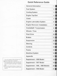
Руководство на английском языке по техническому обслуживанию и ремонту мотоциклов Kawasaki ZX900-A1.
- Издательство: Kawasaki Heavy Industries, Ltd.
- Год издания: —
- Страниц: 293
- Формат: PDF
- Размер: 22,9 Mb
Руководство на английском языке по техническому обслуживанию и ремонту мотоциклов Kawasaki ZX900-C1 и ZX900-D1.
- Издательство: Kawasaki Heavy Industries, Ltd.
- Год издания: —
- Страниц: 307
- Формат: PDF
- Размер: 27,9 Mb
Руководство на немецком языке по техническому обслуживанию и ремонту мотоциклов Kawasaki GPZ1000RX (ZX1000-A1).
- Издательство: Kawasaki Heavy Industries, Ltd.
- Год издания: —
- Страниц: 130
- Формат: PDF
- Размер: 20,8 Mb
Руководство на немецком языке по техническому обслуживанию и ремонту мотоциклов Kawasaki GPZ1100 (ZX1100E).
- Издательство: Kawasaki Heavy Industries, Ltd.
- Год издания: —
- Страниц: 327
- Формат: PDF
- Размер: 10,9 Mb

#1
![]()
motogad
- Пол:Мужчина
- Город:Москва ВАО
- Мото:Kawasaki Ninja ZX6R
Отправлено 18 Август 2008 — 18:34
Все мануалы которые у нас есть ниже по теме
Сообщение отредактировал max232: 31 Январь 2014 — 13:53
- bktspro, Michaelgrorm, SCpraics и 3 другим это нравится
- Наверх
#2
![]()
max232
max232
- Пол:Мужчина
- Страна:Россия
- Город:Елец, Липецкая область
- Мото:zx-10r `08
Отправлено 09 Январь 2014 — 21:19
Просьба к обладателям мануалов которых нет в списке,
мы будем признательны если вы с нами поделитесь.
Руководство по ремонту демпфера Ohlins
Каталог з/ч Kawasaki
Руководство по эксплуатации Kawasaki Ninja H2 (ZX1000NF) 2014-
Руководство по эксплуатации Kawasaki Ninja H2 SX (ZX1000NF) 2017- (РУС) НОВОЕ! Спасибо Mikhail72
Руководство по ремонту KNinja H2 SX 2018- НОВОЕ! Спасибо belenkiy
Руководство по ремонту Kawasaki ZZR1400, ZZR1400 ABS, Ninja ZX-14 2012-2013 (РУС) НОВОЕ! Спасибо Назарий
Руководство пользователя Kawasaki ZZR1400, ZZR1400 ABS, Ninja ZX-14 2012- (РУС) НОВОЕ! Спасибо Ewil Dwarf
Руководство по ремонту Kawasaki ZZR1400, ZZR1400 ABS, Ninja ZX-14 2010-2011
Руководство по ремонту Kawasaki ZZR1400, ZZR1400 ABS, Ninja ZX-14 2008-2009
Руководство по ремонту Kawasaki ZZR1400, ZZR1400 ABS, Ninja ZX-14 2006-2007
Руководство по ремонту Ninja ZX-12R 2002-2005
Руководство по ремонту Ninja ZX-12R 2000-2001
Руководство по ремонту Kawasaki Ninja ZX-10R, Ninja ZX-10R ABS 2016-2017 НОВОЕ!
Руководство по ремонту Kawasaki Ninja ZX-10R, Ninja ZX-10R ABS 2013-2015
Руководство по ремонту Kawasaki Ninja ZX-10R, Ninja ZX-10R ABS 2011-2012
Руководство по эксплуатации (РУС) Kawasaki Ninja ZX-10R 2011-2012
Руководство по эксплуатации (EN) Kawasaki Ninja ZX-10R 2008-2010
Руководство по ремонту Kawasaki Ninja ZX-10R 2008-2010
Руководство по ремонту Kawasaki Ninja ZX-10R 2006-2007
Руководство по ремонту Kawasaki Ninja ZX-10R 2004-2005
Руководство по ремонту Kawasaki Ninja ZX-10 1988-1990
Руководство по ремонту Kawasaki ZX-9R 1998 — 1999
Руководство по ремонту Kawasaki ZX-9R 1998 — 1999 RUS
Руководство по ремонту Kawasaki ZX-9R 1994-1997
Руководство по ремонту Kawasaki ZX-9R (Ger) 2002-2003
Руководство по ремонту Kawasaki ZX750 (ZXR-750) 1989-1996, ZX750 (Ninja ZX-7)1989-1995
Руководство по ремонту Kawasaki Ninja ZX-7R, ZX-7RR 1996-2003
Руководство по ремонту Kawasaki Ninja ZX-6R, Ninja ZX-6R ABS 2013
Руководство по ремонту (РУС пер.Viktor72) Kawasaki Ninja ZX-6R, Ninja ZX-6R ABS 2013
Руководство по ремонту Kawasaki Ninja ZX-6R 2009-2011
Руководство по ремонту Kawasaki ZX-6R 2007-2008
Руководство по ремонту Kawasaki Ninja ZX-6R 2005-2006
Руководство по ремонту Kawasaki Ninja ZX–6R, ZX-6RR 2003-2004
Руководство по ремонту Kawasaki Ninja ZX-6R 2001-2002
Руководство по ремонту Kawasaki Ninja ZX-6R 2001-2002 (РУС) НОВОЕ! Спасибо Vjaceslav
Руководство по ремонту Kawasaki Ninja ZX–6R, 98-99
Руководство по ремонту Kawasaki Ninja ZX-6R 95-97
Руководство по ремонту Kawasaki ZXR400 (zx-4), ZX400-H2 1989-1990
Руководство по ремонту Kawasaki ZXR400 (zx-4), ZX400 L1-L8 1991-1998
Руководство по ремонту Kawasaki ZXR400(zx-4), ZX400 G1,G1A,G1B 1988
Руководство по ремонту Kawasaki Ninja 250 2008-2012
Руководство пользователя Kawasaki Ninja 250 (РУС) 2008-2012
Руководство по ремонту Kawasaki Ninja 300, Ninja 300 ABS 2013-
Руководство по эксплуатации (РУС) Kawasaki Ninja 300, Ninja 300 ABS 2013-
Дорожные мотоциклы Kawasaki. Общее руководство по эксплуатации (РУС) 2012-
Руководство по ремонту Kawasaki ER-6n, ER-6n ABS 2012-
Руководство по эксплуатации (РУС) Kawasaki ER-6n, ER-6n ABS 2012-
Руководство по ремонту Kawasaki ER-6n, ER-6n ABS 2009-2011
Руководство по ремонту Kawasaki ER-6n, ER-6n ABS 2006-2008
Руководство по ремонту Kawasaki Ninja 650, Ninja 650 ABS, ER-6f, ER-6f ABS 2012-
Руководство по эксплуатации (РУС) Kawasaki Ninja 650, Ninja 650 ABS, ER-6f, ER-6f ABS 2012-
Руководство по ремонту Kawasaki Ninja 650, Ninja 650 ABS, ER-6f, ER-6f ABS 2009-2011
Руководство по ремонту Kawasaki NINJA 650R, ER-6f, ER-6f ABS 2006-2008
Руководство по ремонту Kawasaki ER500 C1-C5
2001 ER500-C1 37Kw
2001 ER500-D1 25kw
2002 ER500-C2 37Kw
2003 ER500-C3 37Kw
2004 ER500-C4 катализатор -1Kw
2005 ER500-C5 модифицирован выхлоп, авто выключение/включение света
Руководство по ремонту Kawasaki Z1000, Z1000 ABS 2017- НОВОЕ! Спасибо Назарий
Руководство по ремонту Kawasaki Z1000SX Ninja 1000 2017- НОВОЕ! Спасибо Ghost1195
Руководство по ремонту Kawasaki Z1000SX, Z1000SX ABS, Ninja 1000, Ninja 1000 ABS 2014-2016 НОВОЕ! Спасибо alexus1313
Руководство по ремонту Kawasaki Z1000SX, Z1000SX ABS, Ninja 1000, Ninja 1000 ABS 2011-2013 НОВОЕ! Спасибо Glareone
Руководство по ремонту Kawasaki Z1000, Z1000 ABS 2014-2016
Руководство по ремонту Kawasaki Z1000, Z1000 ABS 2010-2013
Руководство по эксплуатации (РУС) Kawasaki Z1000SX, Z1000SX ABS 2010-2013
Руководство по ремонту Kawasaki Z1000, Z1000 ABS 2007-2009
Руководство по ремонту Kawasaki Z1000 2003-2006
Руководство по ремонту Kawasaki Z900, Z900 ABS, ZR900 2017- НОВОЕ! Спасибо ev6en!
Руководство по ремонту Kawasaki Z800 2013-
Инструкция по эксплуатации Kawasaki Z800 (РУС) 2013-
Инструкция по эксплуатации Kawasaki Z750R (РУС) 2011
Руководство по ремонту Kawasaki Z750S 2005-2006
Руководство по ремонту Kawasaki Z750 2003-2006
Руководство по ремонту Kawasaki Z750, Z750 ABS 2007-2010
Руководство по ремонту Kawasaki Z750R, Z750R ABS 2011- 2012 РОЗЫСК!
Инструкция по эксплуатации Kawasaki Z400 ABS (РУС) 2019- НОВОЕ! Спасибо Бродячий Кот!
Kawasaki 1400GTR, CONCOURS 14 ABS, CONCOURS 14 2010-2014 РОЗЫСК
Kawasaki 1400GTR, CONCOURS 14 ABS, CONCOURS 14 2008-2009
Руководство по эксплуатации (РУС) Kawasaki 1400GTR 2010
Руководство по ремонту Kawasaki VERSYS 650 VERSYS 650 ABS 2015-2016
Руководство по ремонту Kawasaki VERSYS 650 VERSYS 650 ABS 2010-2014
Руководство по ремонту Kawasaki VERSYS 650 2007-2009
Руководство по ремонту Kawasaki VERSYS 1000 2012-2014
Руководство по эксплуатации (РУС) Kawasaki VERSYS 1000 2012-2014
Руководство по эксплуатации (РУС) Kawasaki VERSYS 1000 SE 2019 — НОВОЕ!
Руководство по эксплуатации (РУС) Kawasaki VULCAN S VULCAN S ABS 2015- НОВОЕ! Спасибо offlineb!
Руководство по эксплуатации (РУС) Kawasaki W800 2012-
Руководство по эксплуатации (РУС) Kawasaki KLX250
Руководство по эксплуатации (ENG) Kawasaki KLX150L 2014- НОВОЕ!Спасибо roy0864!
Руководство по эксплуатации (РУС) Kawasaki 1000GTR ZG1000-A1 1986
Все что у нас есть выложено здесь, и мы больше ничего от Вас не прячем. Затрудните себя хотя бы поиском в списке мануала для своей модели мотоцикла.
По этим ссылкам расположены 2 архива по гигабайту с мануалами которых нет в вышеуказанном списке.
http://yadi.sk/d/yrnnmcxJJ9wxG
http://yadi.sk/d/nxb6nuh_J9x52
Эта ссылка на теже мануалы с возможностью не скачивать архивы целиком https://yadi.sk/d/OzesQZ8RUrXPE
- mrkvch, EnergyControl, Walazar и еще 1 это нравится
- Наверх
#3
![]()
Smart
Smart
- Пол:Мужчина
- Страна:Россия
- Город:Митино
- Мото:9-ka 1999г—>9-ka 2001г
Отправлено 17 Январь 2014 — 11:26
По ссылке https://yadi.sk/d/I61_p9A6mdk6m находятся мануалы на следующие модели которые не вошли в список выложенный выше.
Kawasaki ZZR1100 & ZX11 1993-2001
Kawasaki NINJA 250 86-07
Kawasaki GPZ400-550 & Z400F-FII & Z500F-550F 83-85 Service Manual
Kawasaki GPZ-500,600,ZX-500-A1,ZX-600-A1 Service Manual
Kawasaki GPZ-500S 86-94 Service Manual
Kawasaki GPZ-600R/GPX-600R/Ninja 600R/RX/GPX-750R/Ninja 750R
Kawasaki GPZ-750 Turbo 1984 Service Manual
Kawasaki GPZ900R 1984-1990 Workshop Manual
Kawasaki GPZ-1000RX,GPZ-900R Service Manual
Kawasaki GPZ-1100E Service Manual
Kawasaki GTR-1400 2014 Service Manual
Kawasaki KDX200 89-94 Service Manual
Kawasaki KH250-400 72-76
Kawasaki KLV1000-A1 2004 Service Manual
Kawasaki KLX650
Kawasaki KR250
Kawasaki KX250F 2004 Service Manual
Kawasaki KX450F 2006 Service Manual
Kawasaki KZ400 1974 Service Manual
Kawasaki KZ440 Service Manual
Kawasaki VN1500 87-99 Service Manual
Kawasaki VN1600-A1&A2 2003 Service Manual
Kawasaki VN2000-A1 2003 Service Manual
Kawasaki VN750 Manual and Parts
Kawasaki ZZR250 90-96 Service Manual
Kawasaki A Series Rotary Valve Twins 250,350,500 69-71 Workshop Manual
Kawasaki EN450,EN500,EN454,LTD500 Vulcan 85-04 Service Manual
Kawasaki ER-5 2004 Service Manual
Kawasaki ER-5 1997 Service Manual(DE)
Kawasaki VN800 Vulcan 96-04 Service Manual
Kawasaki VN900 Vulcan Classic 2006 Service Manual
Kawasaki W650 ’99 Service Manual (German)
Kawasaki ZR1100A,Zephir-1100 Service Manual
Kawasaki ZRX1200R,ZRX1200S 2001-2007 Service Manual
Kawasaki ZR550,ZR750 Zephyr 1990 Service Manual
Kawasaki ZR-7S,ZR-750H1 Service Manual
Kawasaki ZXR400R Kit 1989 Service Manual
Kawasaki ZXR400L Service Manual
Kawasaki ZXR750R,ZXR750J,ZXR750K Service Manual
Kawasaki ZXR750 Racing Kit 1992 Service Manual
Kawasaki ZX-10 Ninja 1988-1990 Service Manual
Kawasaki ZZR1200 ’03 Service Manual (German)
Kawasaki Z1 1972 Service Manual
Kawasaki KLE500 Service Manual
Kawasaki ZRX1200 Service Manual(German)
Kawasaki KLX110 Service Manual
Kawasaki ZXR 250 Service Manual 1997
- sem01 и Walazar это нравится
- Наверх
#4
![]()
albert8121984
albert8121984
-

- Members
-
- 35 сообщений
Прохожий


- Пол:Мужчина
- Страна:Россия
- Город:Москва СВАО(Алтуфьево), (КБР г.Прохладный)
- Мото:Kawasaki Z1000SX, (Versys 650B-08г), (ZX-6R 636 05г.) (ZZR 400 — 2)
Отправлено 16 Октябрь 2015 — 14:29
Пользуюсь сайтом ManualsLib – Search For Manuals Online.
Если что-то не понятно с помощью googla можно перевести страничку.
- Cher Tannov это нравится
- Наверх
#5
![]()
Cher Tannov
Cher Tannov
-
Вконтакте:
- Пол:Мужчина
- Страна:Россия
- Город:Москва, Чер Танново
- Мото:ER-6F ’12
Отправлено 06 Апрель 2016 — 10:32
Каталог Hiflo по масляным и воздушным фильтрам: https://yadi.sk/i/8FAFZ19PqmkhH
Немало каталогов и мануалов на тайском сайте Кавасаки.
http://www.kawasaki….c&page=download
ONLINE КАТАЛОГИ
Каталоги производителей, представленных в наших магазинах. Ссылки открываются в новом окне.
HIFLOFILTRO — Воздушные и маслянные фильтры
MOTUL — Моторные масла и мотохимия
JTSPROKETS — Звёзды и цепи привода
LUCAS TRW — Тормозные колодки
FERODO — Тормозные колодки
NGK — Свечи зажигания
ARIETE — Сальники и пыльники вилки
ALL BALLS RACING — Подшипники рулевой колонки
Сообщение отредактировал Cher Tannov: 06 Май 2016 — 11:35
- Coreydus и gtaemblem.club это нравится
- Наверх
#6
![]()
max232
max232
- Пол:Мужчина
- Страна:Россия
- Город:Елец, Липецкая область
- Мото:zx-10r `08
Отправлено 19 Сентябрь 2019 — 15:43
Ребята, думаю навести в этом разделе порядок.
Если просто так скидывать ссылки, без указания точной модели для разных рынков,от какого года до какого года, сервисный мануал/руководство по эксплуатации, на каком языке.
Этот раздел очень быстро превратиться в помойку в котором невозможно ничего найти.
Зачастую люди кидают ссылки на то что у нас уже есть.
Очень много мото для разных рынков называются по разному.
Я вроде недалекий человек от мото, но и мне не просто разобраться какие модели одинаковые а какие нет.
Пожалуйста, если у вас есть чем поделиться указывайте как минимум следующую информацию:
1. точная модель мотоцикла
2. модельный год. (от какого года и ДО какого года)
3. Сервисный мануал или руководство по эксплуатации
4. На каком языке издание
5. Ссылка
БЕЗ УКАЗАНИЯ ЭТОЙ ИНФОРМАЦИИ Я БУДУ УДАЛЯТЬ ПОСТЫ
- Наверх
#7
![]()
ведьмак 24
ведьмак 24
-
- Читатели
- 1 сообщений

- Пол:Мужчина
- Страна:россия
- Город:иркутск
- Мото:кавасаки илиминатор VN250
Отправлено 22 Октябрь 2020 — 09:40
а не подскажеш где найти мануал на кавасаки илименатор вн 250,нигде найти не могу
- Наверх
#8
![]()
max232
max232
- Пол:Мужчина
- Страна:Россия
- Город:Елец, Липецкая область
- Мото:zx-10r `08
Отправлено 13 Апрель 2021 — 12:14
а не подскажеш где найти мануал на кавасаки илименатор вн 250,нигде найти не могу
https://www.ebay.com.au/p/2185422503
- Наверх
#9
![]()
Назарий
Назарий
-
- Читатели
- 6 сообщений

- Пол:Мужчина
- Страна:Россия
- Город:Москва
- Мото:Z1000
Отправлено 18 Август 2021 — 16:39
- Наверх
#10
![]()
max232
max232
- Пол:Мужчина
- Страна:Россия
- Город:Елец, Липецкая область
- Мото:zx-10r `08
Отправлено 19 Август 2021 — 00:27
- Наверх
#11
![]()
Lavarock
Lavarock
-
- Читатели
- 1 сообщений

- Пол:Мужчина
- Страна:Россия
- Город:Сочи
- Мото:z650
Отправлено 14 Декабрь 2021 — 21:53
Помогите найти мануал на Z650 2017 год
- Наверх
#12
![]()
advokat56
advokat56
-
- Читатели
- 1 сообщений

- Пол:Мужчина
- Страна:РФ
- Город:Оренбург
- Мото:Ninja 1000SX
Отправлено 25 Январь 2022 — 18:44
Доброе время суток! Поменял свой мот на Ninja 1000SX 2020 г. долго искал мануал на русском. Нашел делюсь. https://e-kawasaki.r…ba66894759a.pdf
- Наверх
#13
![]()
belenkiy
belenkiy
-
- Читатели
- 3 сообщений

- Пол:Мужчина
- Страна:Россия
- Город:Москва
- Мото:fz6r
Отправлено 15 Май 2022 — 18:50
Руководство по ремонту — Kawasaki h2 2018
https://1drv.ms/b/s!…-l2jLg?e=kLBago
К сожалени к SX не смог найти
- Наверх
#14
![]()
max232
max232
- Пол:Мужчина
- Страна:Россия
- Город:Елец, Липецкая область
- Мото:zx-10r `08
Отправлено 15 Май 2022 — 22:10
По вашей ссылке именно SX
Я добавил к списку. спасибо!
- Наверх
#15
![]()
Denisik
Denisik
-
- Читатели
- 1 сообщений

- Пол:Мужчина
- Страна:Россия
- Город:Вологда
- Мото:Z250
Отправлено 16 Сентябрь 2022 — 10:20
Руководство по эксплуатации Kawasaki Z250
https://disk.yandex…./zXaOezF2k7TSSQ
- Наверх
#16
![]()
L0ckhead
L0ckhead
-
- Members
-
- 20 сообщений
Прохожий

- Пол:Мужчина
- Страна:Россия
- Город:Краснознаменск
- Мото:Kawasaki Ninja 1000 sx
Отправлено 26 Март 2023 — 20:52
Мб кому пригодится мануал на ninja 1000 sx 2020+ Файл можно получить по ссылке:
Ninja 1000 sx.pdf
https://disk.yandex…./ddmFwjH-2Lc4Yg
- Наверх
#17
![]()
L0ckhead
L0ckhead
-
- Members
-
- 20 сообщений
Прохожий
- Пол:Мужчина
- Страна:Россия
- Город:Краснознаменск
- Мото:Kawasaki Ninja 1000 sx
Отправлено 26 Март 2023 — 20:53
Дубль
- Наверх
#18
![]()
AnDrRew
AnDrRew
-
- Читатели
- 4 сообщений

- Пол:Мужчина
- Страна:Russia
- Город:Moscow
- Мото:Ninja 1000
Отправлено 08 Апрель 2023 — 14:39
На manualslib больше нет наших мануалов((
Пока искал сервис мануал для своего мотоцикла нашёл:
Руководство пользователя z1000sx ninja1000 2017-19 на русском языке
https://docviewer.ya…m89MCJ9&lang=ru
- Наверх
#19
![]()
AnDrRew
AnDrRew
-
- Читатели
- 4 сообщений
- Пол:Мужчина
- Страна:Russia
- Город:Moscow
- Мото:Ninja 1000
Отправлено 08 Апрель 2023 — 14:40
На manualslib больше нет наших мануалов((
Пока искал сервис мануал для своего мотоцикла нашёл:
Руководство пользователя z1000sx ninja1000 2017-19 на русском языке
https://mot63.ru/upl…6e444596981.pdf
- Наверх
Если у вас отсутствует техническая возможность для скачивания Инструкция по эксплуатации для Kawasaki NINJA ZX-10R
вы можете прочесть документ прямо на нашем сайте или
Скачать Kawasaki NINJA ZX-10R Инструкция по эксплуатации
BB кодПрямая ссылка
- 1
- 2
- 3
- …
- 6
 1
1 2
2 3
3 6
6
- 1
- 2
- 3
- 4
- 5
- 6
- 7
Инструкции для прочих Kawasaki NINJA ZX-10R
-
Kawasaki NINJA ZX-10R Инструкция по эксплуатации
Популярность:
205 просмотры
Подсчет страниц:
81 страницы
Тип файла:
PDF
Размер файла:
2.49 Mb
Скачать (PDF 2.49 Mb) Читать онлайн (81 страницы)

Инструкции для прочих Kawasaki Мотоциклы
-
Kawasaki FX671V Инструкция по эксплуатации
Популярность:
1088 просмотры
Подсчет страниц:
3 страницы
Тип файла:
PDF
Размер файла:
143 Kb
Скачать (PDF 143 Kb) Читать онлайн (3 страницы)
-
Kawasaki FS730V Инструкция по эксплуатации
Популярность:
1093 просмотры
Подсчет страниц:
3 страницы
Тип файла:
PDF
Размер файла:
143 Kb
Скачать (PDF 143 Kb) Читать онлайн (3 страницы)
-
Kawasaki FR730V Инструкция по эксплуатации
Популярность:
1095 просмотры
Подсчет страниц:
3 страницы
Тип файла:
PDF
Размер файла:
143 Kb
Скачать (PDF 143 Kb) Читать онлайн (3 страницы)
-
Kawasaki FX481V Инструкция по эксплуатации
Популярность:
1096 просмотры
Подсчет страниц:
3 страницы
Тип файла:
PDF
Размер файла:
143 Kb
Скачать (PDF 143 Kb) Читать онлайн (3 страницы)
-
Kawasaki FR/FS/FX Series Инструкция по эксплуатации
Популярность:
1103 просмотры
Подсчет страниц:
3 страницы
Тип файла:
PDF
Размер файла:
143 Kb
Скачать (PDF 143 Kb) Читать онлайн (3 страницы)
-
Kawasaki FS691V Инструкция по эксплуатации
Популярность:
1108 просмотры
Подсчет страниц:
3 страницы
Тип файла:
PDF
Размер файла:
143 Kb
Скачать (PDF 143 Kb) Читать онлайн (3 страницы)
-
Kawasaki FX600V Инструкция по эксплуатации
Популярность:
1115 просмотры
Подсчет страниц:
3 страницы
Тип файла:
PDF
Размер файла:
143 Kb
Скачать (PDF 143 Kb) Читать онлайн (3 страницы)
-
Kawasaki FR600V Инструкция по эксплуатации
Популярность:
1135 просмотры
Подсчет страниц:
3 страницы
Тип файла:
PDF
Размер файла:
143 Kb
Скачать (PDF 143 Kb) Читать онлайн (3 страницы)
-
Kawasaki FS651V Инструкция по эксплуатации
Популярность:
1139 просмотры
Подсчет страниц:
3 страницы
Тип файла:
PDF
Размер файла:
143 Kb
Скачать (PDF 143 Kb) Читать онлайн (3 страницы)
-
Kawasaki KLR250 Инструкция по эксплуатации
Популярность:
1141 просмотры
Подсчет страниц:
2 страницы
Тип файла:
PDF
Размер файла:
27 Kb
Скачать (PDF 27 Kb) Читать онлайн (2 страницы)


Инструкции для прочих Kawasaki
-
Kawasaki Аккумуляторные дисковые (циркулярные) пилы 840067 Инструкция по эксплуатации
Популярность:
971 просмотры
Подсчет страниц:
11 страницы
Тип файла:
PDF
Размер файла:
283 Kb
Скачать (PDF 283 Kb) Читать онлайн (11 страницы)
-
Kawasaki Аккумуляторные дисковые (циркулярные) пилы 840184 Инструкция по эксплуатации
Популярность:
976 просмотры
Подсчет страниц:
11 страницы
Тип файла:
PDF
Размер файла:
736 Kb
Скачать (PDF 736 Kb) Читать онлайн (11 страницы)
-
Kawasaki Аккумуляторные дисковые (циркулярные) пилы 840442 Инструкция по эксплуатации
Популярность:
976 просмотры
Подсчет страниц:
13 страницы
Тип файла:
PDF
Размер файла:
928 Kb
Скачать (PDF 928 Kb) Читать онлайн (13 страницы)
-
Kawasaki Автомобильные аксессуары 70Z IV-2 Инструкция по эксплуатации
Популярность:
976 просмотры
Подсчет страниц:
12 страницы
Тип файла:
PDF
Размер файла:
768 Kb
Скачать (PDF 768 Kb) Читать онлайн (12 страницы)
-
Kawasaki Пилы 843327 Инструкция по эксплуатации
Популярность:
977 просмотры
Подсчет страниц:
13 страницы
Тип файла:
PDF
Размер файла:
1.24 Mb
Скачать (PDF 1.24 Mb) Читать онлайн (13 страницы)
-
Kawasaki Аккумуляторные дисковые (циркулярные) пилы 840068 Инструкция по эксплуатации
Популярность:
977 просмотры
Подсчет страниц:
10 страницы
Тип файла:
PDF
Размер файла:
473 Kb
Скачать (PDF 473 Kb) Читать онлайн (10 страницы)
-
Kawasaki Прицеп общего назначения ZX1200-B3H (2004) Инструкция по эксплуатации
Популярность:
977 просмотры
Подсчет страниц:
2 страницы
Тип файла:
PDF
Размер файла:
59 Kb
Скачать (PDF 59 Kb) Читать онлайн (2 страницы)
-
Kawasaki Аккумуляторные дисковые (циркулярные) пилы 840844 Инструкция по эксплуатации
Популярность:
978 просмотры
Подсчет страниц:
10 страницы
Тип файла:
PDF
Размер файла:
719 Kb
Скачать (PDF 719 Kb) Читать онлайн (10 страницы)
-
Kawasaki Дробилки 840330 Инструкция по эксплуатации
Популярность:
978 просмотры
Подсчет страниц:
10 страницы
Тип файла:
PDF
Размер файла:
901 Kb
Скачать (PDF 901 Kb) Читать онлайн (10 страницы)
-
Kawasaki Гайковерты 690163 Инструкция по эксплуатации
Популярность:
978 просмотры
Подсчет страниц:
8 страницы
Тип файла:
PDF
Размер файла:
236 Kb
Скачать (PDF 236 Kb) Читать онлайн (8 страницы)