![]()
4-я Красноармейская, 2А
Санкт-Петербург, 190005
Email: info@lenmoto.ru
Телефон: +7 (921) 930-81-18
Телефон: +7 (911) 928-08-06
Компания ЛенМото
Запчасти, аксессуары, экипировка, тюнинг для мотоциклов, скутеров, квадроциклов, снегоходов, багги, гидроциклов, катеров и лодочных моторов.
Подпишитесь на наши новости
Подписаться
Скрыть/показать содержание
Материал из BikesWiki, Энциклопедия японских мотоциклов
Owner’s Manual VN900BCF (2012)
Item # 99987-1701
MSRP
$18.15
Kawasaki Owner’s Manuals include Important Safety Information, Operating Instructions, and Maintenance and Storage Information.
Most items ship to dealer within 5-7 business days for free. Special dealer only items may be excluded.
Additional shipping charges apply to qualified ship to home orders.
Price and specifications are subject to change without notice or liability. Availability is subject to production, stocking and demand. Manufacturers suggested retail prices shown.
 WARNING: Cancer and reproductive harm www.P65Warnings.ca.gov
- WARRANTY INFORMATION
![]()
VULCAN900 CLASSIC
VULCAN900 CLASSIC LT
VN900 CLASSIC
Motorcycle
Service Manual

Quick Reference Guide
This quick reference guide will assist you in locating a desired topic or procedure.
•Bend the pages back to match the black tab of the desired chapter number with the black tab on the edge at each table of contents page.
•Refer to the sectional table of contents for the exact pages to locate the specific topic required.
|
General Information |
1 |
j |
|
Periodic Maintenance |
2 |
j |
|
Fuel System (DFI) |
3 |
j |
|
Cooling System |
4 |
j |
|
Engine Top End |
5 |
j |
|
Clutch |
6 |
j |
|
Engine Lubrication System |
7 |
j |
|
Engine Removal/Installation |
8 |
j |
|
Crankshaft/Transmission |
9 |
j |
|
Wheels/Tires |
10 |
j |
|
Final Drive |
11 |
j |
|
Brakes |
12 |
j |
|
Suspension |
13 |
j |
|
Steering |
14 |
j |
|
Frame |
15 |
j |
|
Electrical System |
16 |
j |
|
Appendix |
17 |
j |

VULCAN900 CLASSIC
VULCAN900 CLASSIC LT
VN900 CLASSIC
Motorcycle
Service Manual
All rights reserved. No parts of this publication may be reproduced, stored in a retrieval system, or transmitted in any form or by any means, electronic mechanical photocopying, recording or otherwise, without the prior written permission of Quality Division/Consumer Products & Machinery Company/Kawasaki Heavy Industries, Ltd., Japan.
No liability can be accepted for any inaccuracies or omissions in this publication, although every possible care has been taken to make it as complete and accurate as possible.
The right is reserved to make changes at any time without prior notice and without incurring an obligation to make such changes to products manufactured previously. See your motorcycle dealer for the latest information on product improvements incorporated after this publication.
All information contained in this publication is based on the latest product information available at the time of publication. Illustrations and photographs in this publication are intended for reference use only and may not depict actual model component parts.
|
© 2006 Kawasaki Heavy Industries, Ltd. |
First Edition (1): Feb. 7, 2006 (M) |
LIST OF ABBREVIATIONS
|
A |
ampere(s) |
lb |
pounds(s) |
|
ABDC |
after bottom dead center |
m |
meter(s) |
|
AC |
alternating current |
min |
minute(s) |
|
ATDC |
after top dead center |
N |
newton(s) |
|
BBDC |
before bottom dead center |
Pa |
pascal(s) |
|
BDC |
bottom dead center |
PS |
horsepower |
|
BTDC |
before top dead center |
psi |
pound(s) per square inch |
|
°C |
degree(s) Celsius |
r |
revolution |
|
DC |
direct current |
rpm |
revolution(s) per minute |
|
F |
farad(s) |
TDC |
top dead center |
|
°F |
degree(s) Fahrenheit |
TIR |
total indicator reading |
|
ft |
foot, feet |
V |
volt(s) |
|
g |
gram(s) |
W |
watt(s) |
|
h |
hour(s) |
Ω |
ohm(s) |
|
L |
liter(s) |

EMISSION CONTROL INFORMATION
To protect the environment in which we all live, Kawasaki has incorporated crankcase emission (1) and exhaust emission (2) control systems in compliance with applicable regulations of the United States Environmental Protection Agency and California Air Resources Board. Additionally, Kawasaki has incorporated an evaporative emission control system (3) in compliance with applicable regulations of the California Air Resources Board on vehicles sold in California only.
1. Crankcase Emission Control System
This system eliminates the release of crankcase vapors into the atmosphere. Instead, the vapors are routed through an oil separator to the inlet side of the engine. While the engine is operating, the vapors are drawn into combustion chamber, where they are burned along with the fuel and air supplied by the fuel injection system.
2. Exhaust Emission Control System
This system reduces the amount of pollutants discharged into the atmosphere by the exhaust of this motorcycle. The fuel, ignition, and exhaust systems of this motorcycle have been carefully designed and constructed to ensure an efficient engine with low exhaust pollutant levels.
The exhaust system of this model motorcycle manufactured primarily for sale in California includes a catalytic converter system.
3. Evaporative Emission Control System
Vapors caused by fuel evaporation in the fuel system are not vented into the atmosphere. Instead, fuel vapors are routed into the running engine to be burned, or stored in a canister when the engine is stopped. Liquid fuel is caught by a vapor separator and returned to the fuel tank.
The Clean Air Act, which is the Federal law covering motor vehicle pollution, contains what is commonly referred to as the Act’s «tampering provisions.»
«Sec. 203(a) The following acts and the causing thereof are prohibited…
(3)(A) for any person to remove or render inoperative any device or element of design installed on or in a motor vehicle or motor vehicle engine in compliance with regulations under this title prior to its sale and delivery to the ultimate purchaser, or for any manufacturer or dealer knowingly to remove or render inoperative any such device or element of design after such sale and delivery to the ultimate purchaser.
(3)(B) for any person engaged in the business of repairing, servicing, selling, leasing, or trading motor vehicles or motor vehicle engines, or who operates a fleet of motor vehicles knowingly to remove or render inoperative any device or element of design installed on or in a motor vehicle or motor vehicle engine in compliance with regulations under this title following its sale and delivery to the ultimate purchaser…»
NOTE
○The phrase «remove or render inoperative any device or element of design» has been generally interpreted as follows:
1.Tampering does not include the temporary removal or rendering inoperative of devices or elements of design in order to perform maintenance.
2.Tampering could include:
a.Maladjustment of vehicle components such that the emission standards are exceeded.
b.Use of replacement parts or accessories which adversely affect the performance or durability of the motorcycle.
c.Addition of components or accessories that result in the vehicle exceeding the standards.
d.Permanently removing, disconnecting, or rendering inoperative any component or element of design of the emission control systems.
WE RECOMMEND THAT ALL DEALERS OBSERVE THESE PROVISIONS OF FEDERAL LAW, THE VIOLATION OF WHICH IS PUNISHABLE BY CIVIL PENALTIES NOT EXCEEDING $10,000 PER VIOLATION.

TAMPERING WITH NOISE CONTROL SYSTEM PROHIBITED
Federal law prohibits the following acts or the causing thereof: (1) The removal or rendering inoperative by any person other than for purposes of maintenance, repair, or replacement, of any device or element of design incorporated into any new vehicle for the purpose of noise control prior to its sale or delivery to the ultimate purchaser or while it is in use, or (2) the use of the vehicle after such device or element of design has been removed or rendered inoperative by any person.
Among those acts presumed to constitute tampering are the acts listed below:
•Replacement of the original exhaust system or muffler with a component not in compliance with Federal regulations.
•Removal of the muffler(s) or any internal portion of the muffler(s).
•Removal of the air box or air box cover.
•Modifications to the muffler(s) or air intake system by cutting, drilling, or other means if such modifications result in increased noise levels.

Foreword
This manual is designed primarily for use by trained mechanics in a properly equipped shop. However, it contains enough detail and basic information to make it useful to the owner who desires to perform his own basic maintenance and repair work. A basic knowledge of mechanics, the proper use of tools, and workshop procedures must be understood in order to carry out maintenance and repair satisfactorily. Whenever the owner has insufficient experience or doubts his ability to do the work, all adjustments, maintenance, and repair should be carried out only by qualified mechanics.
In order to perform the work efficiently and to avoid costly mistakes, read the text, thoroughly familiarize yourself with the procedures before starting work, and then do the work carefully in a clean area. Whenever special tools or equipment are specified, do not use makeshift tools or equipment. Precision measurements can only be made if the proper instruments are used, and the use of substitute tools may adversely affect safe operation.
For the duration of the warranty period, we recommend that all repairs and scheduled maintenance be performed in accordance with this service manual. Any owner maintenance or repair procedure not performed in accordance with this manual may void the warranty.
To get the longest life out of your vehicle:
•Follow the Periodic Maintenance Chart in the Service Manual.
•Be alert for problems and non-scheduled maintenance.
•Use proper tools and genuine Kawasaki Motorcycle parts. Special tools, gauges, and testers that are necessary when servicing Kawasaki motorcycles are introduced by the Service Manual. Genuine parts provided as spare parts are listed in the Parts Catalog.
•Follow the procedures in this manual carefully. Don’t take shortcuts.
•Remember to keep complete records of maintenance and repair with dates and any new parts installed.
How to Use This Manual
In preparing this manual, we divided the product into its major systems. These systems became the manual’s chapters. All information for a particular system from adjustment through disassembly and inspection is located in a single chapter.
The Quick Reference Guide shows you all of the product’s system and assists in locating their chapters. Each chapter in turn has its own comprehensive Table of Contents.
The Periodic Maintenance Chart is located in the Periodic Maintenance chapter. The chart gives a time schedule for required maintenance operations.
If you want spark plug information, for example, go to the Periodic Maintenance Chart first. The chart tells you how frequently to clean and gap the plug. Next, use the Quick Reference Guide to locate the Periodic Maintenance chapter. Then, use the Table of Contents on the first page of the chapter to find the Spark Plug section.
Whenever you see these WARNING and CAUTION symbols, heed their instructions! Always follow safe operating and maintenance practices.

 WARNING
This warning symbol identifies special instructions or procedures which, if not correctly followed, could result in personal injury, or loss of life.
CAUTION
This caution symbol identifies special instructions or procedures which, if not strictly observed, could result in damage to or destruction of equipment.
This manual contains four more symbols (in addition to WARNING and CAUTION) which will help you distinguish different types of information.
NOTE
○This note symbol indicates points of particular interest for more efficient and convenient operation.
•Indicatesdone. a procedural step or work to be ○Indicates a procedural sub-step or how to do the work of the procedural step it follows. It
also precedes the text of a NOTE.
 Indicates a conditional step or what action to take based on the results of the test or inspection in the procedural step or sub-step it follows.
In most chapters an exploded view illustration of the system components follows the Table of Contents. In these illustrations you will find the instructions indicating which parts require specified tightening torque, oil, grease or a locking agent during assembly.
![]()
GENERAL INFORMATION 1-1
General Information |
|
|
Table of Contents |
|
|
1 |
|
|
Before Servicing ……………………………………………………………………………………………………… |
1-2 |
|
Model Identification………………………………………………………………………………………………….. |
1-7 |
|
General Specifications……………………………………………………………………………………………… |
1-10 |
|
Unit Conversion Table ……………………………………………………………………………………………… |
1-13 |
1-2 GENERAL INFORMATION
Before Servicing
Before starting to perform an inspection service or carry out a disassembly and reassembly operation on a motorcycle, read the precautions given below. To facilitate actual operations, notes, illustrations, photographs, cautions, and detailed descriptions have been included in each chapter wherever necessary. This section explains the items that require particular attention during the removal and reinstallation or disassembly and reassembly of general parts.
Especially note the following:
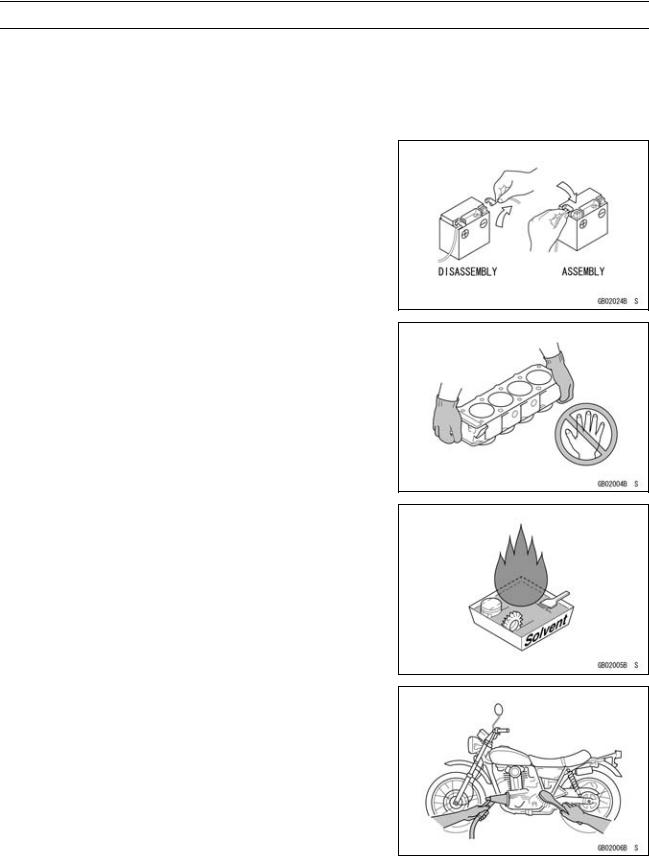
Battery Ground
Before completing any service on the motorcycle, disconnect the battery cables from the battery to prevent the engine from accidentally turning over. Disconnect the ground cable (–) first and then the positive (+). When completed with the service, first connect the positive (+) cable to the positive (+) terminal of the battery then the negative (–) cable to the negative terminal.
Edges of Parts
Lift large or heavy parts wearing gloves to prevent injury from possible sharp edges on the parts.
Solvent
Use a high-flush point solvent when cleaning parts. High -flush point solvent should be used according to directions of the solvent manufacturer.
Cleaning Vehicle before Disassembly
Clean the vehicle thoroughly before disassembly. Dirt or other foreign materials entering into sealed areas during vehicle disassembly can cause excessive wear and decrease performance of the vehicle.
GENERAL INFORMATION 1-3
Before Servicing
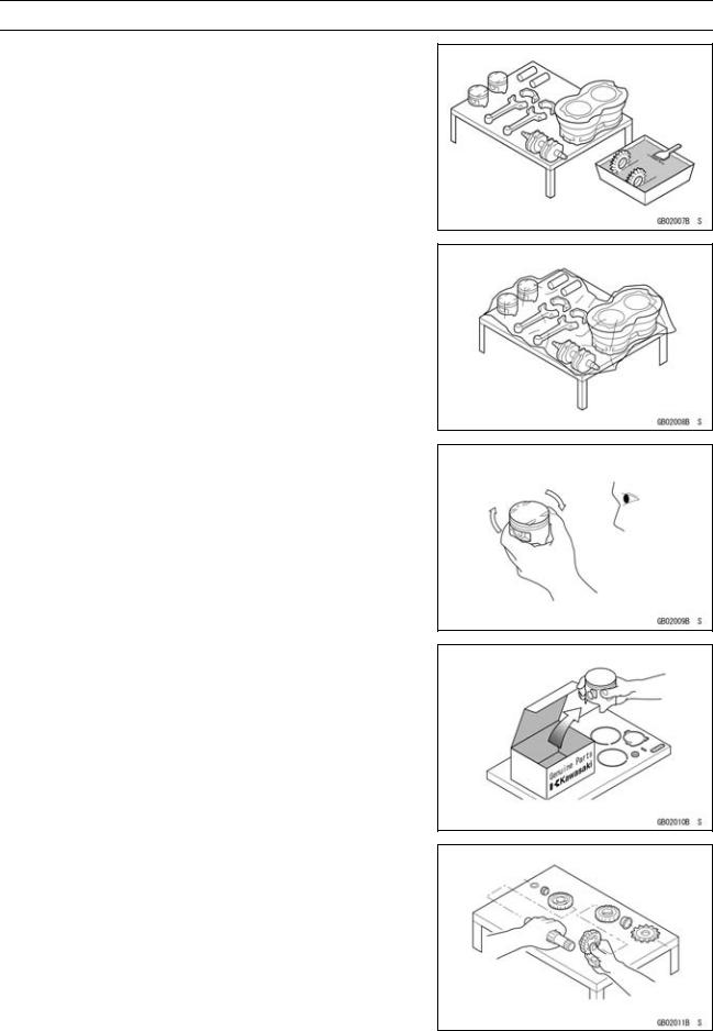
Arrangement and Cleaning of Removed Parts
Disassembled parts are easy to confuse. Arrange the parts according to the order the parts were disassembled and clean the parts in order prior to assembly.
Storage of Removed Parts
After all the parts including subassembly parts have been cleaned, store the parts in a clean area. Put a clean cloth or plastic sheet over the parts to protect from any foreign materials that may collect before re-assembly.
Inspection
Reuse of worn or damaged parts may lead to serious accident. Visually inspect removed parts for corrosion, discoloration, or other damage. Refer to the appropriate sections of this manual for service limits on individual parts. Replace the parts if any damage has been found or if the part is beyond its service limit.
Replacement Parts
Replacement parts must be KAWASAKI genuine or recommended by KAWASAKI. Gaskets, O-rings, oil seals, grease seals, circlips or cotter pins must be replaced with new ones whenever disassembled.
Assembly Order
In most cases assembly order is the reverse of disassembly, however, if assembly order is provided in this Service Manual, follow the procedures given.
1-4 GENERAL INFORMATION
Before Servicing
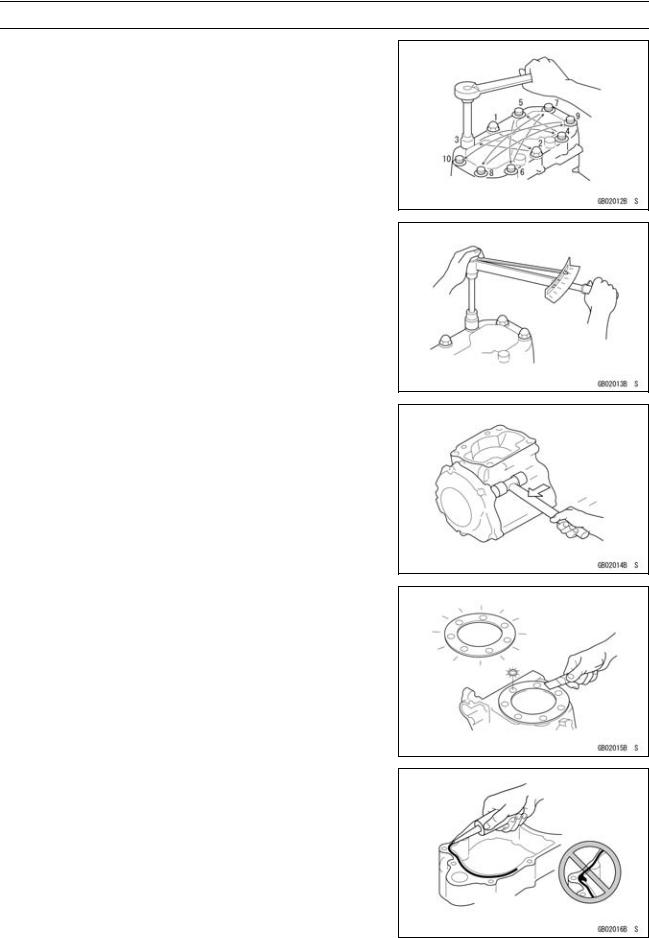
Tightening Sequence
Generally, when installing a part with several bolts, nuts, or screws, start them all in their holes and tighten them to a snug fit. Then tighten them according to the specified sequence to prevent case warpage or deformation which can lead to malfunction. Conversely when loosening the bolts, nuts, or screws, first loosen all of them by about a quarter turn and then remove them. If the specified tightening sequence is not indicated, tighten the fasteners alternating diagonally.
Tightening Torque
Incorrect torque applied to a bolt, nut, or screw may lead to serious damage. Tighten fasteners to the specified torque using a good quality torque wrench. Often, the tightening sequence is followed twice-initial tightening and final tightening with torque wrench.
Force
Use common sense during disassembly and assembly, excessive force can cause expensive or hard to repair damage. When necessary, remove screws that have a non -permanent locking agent applied using an impact driver. Use a plastic-faced mallet whenever tapping is necessary.
Gasket, O-ring
Hardening, shrinkage, or damage of both gaskets and O-rings after disassembly can reduce sealing performance. Remove old gaskets and clean the sealing surfaces thoroughly so that no gasket material or other material remains. Install new gaskets and replace used O-rings when re-assembling
Liquid Gasket, Non-permanent Locking Agent
For applications that require Liquid Gasket or a Non-permanent Locking Agent, clean the surfaces so that no oil residue remains before applying liquid gasket or non-permanent locking agent. Do not apply them excessively. Excessive application can clog oil passages and cause serious damage.
GENERAL INFORMATION 1-5
Before Servicing
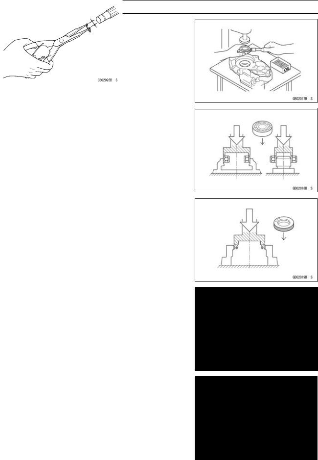
Press
For items such as bearings or oil seals that must be pressed into place, apply small amount of oil to the contact area. Be sure to maintain proper alignment and use smooth movements when installing.
Ball Bearing and Needle Bearing
Do not remove pressed ball or needle unless removal is absolutely necessary. Replace with new ones whenever removed. Press bearings with the manufacturer and size marks facing out. Press the bearing into place by putting pressure on the correct bearing race as shown.
Pressing the incorrect race can cause pressure between the inner and outer race and result in bearing damage.
Oil Seal, Grease Seal
Do not remove pressed oil or grease seals unless removal is necessary. Replace with new ones whenever removed. Press new oil seals with manufacture and size marks facing out. Make sure the seal is aligned properly when installing.
Apply specified grease to the lip of seal before installing the seal.
Circlips, Cotter Pins
Replace circlips or cotter pins that were removed with new ones. Take care not to open the clip excessively when installing to prevent deformation.
1-6 GENERAL INFORMATION
Before Servicing
Lubrication
It is important to lubricate rotating or sliding parts during assembly to minimize wear during initial operation. Lubrication points are called out throughout this manual, apply the specific oil or grease as specified.
Direction of Engine Rotation
When rotating the crankshaft by hand, the free play amount of rotating direction will affect the adjustment. Rotate the crankshaft to positive direction (clockwise viewed from output side).
Electrical Wires
A two-color wire is identified first by the primary color and then the stripe color. Unless instructed otherwise, electrical wires must be connected to those of the same color.
Instrument
Use a meter that has enough accuracy for an accurate measurement. Read the manufacture’s instructions thoroughly before using the meter. Incorrect values may lead to improper adjustments.
GENERAL INFORMATION 1-7
Model Identification
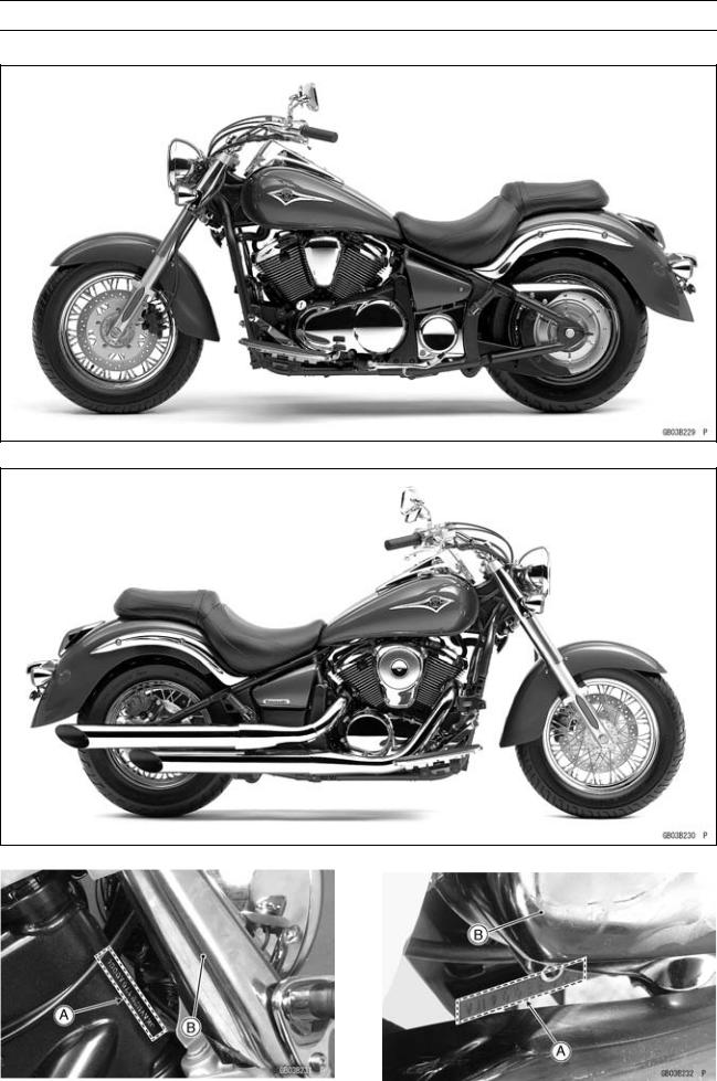
VN900B6F (US and Canada) Left Side View:
VN900B6F (US and Canada) Right Side View:
Frame Number |
Engine Number |
|
[A]Frame Number
[B]Front Fork (Right side)
[A]Engine Number
[B]Right Engine Cover
1-8 GENERAL INFORMATION
Model Identification
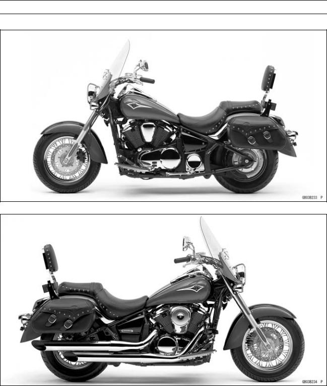
VN900B6F (Europe and Australia) Left Side View:
VN900B6F (Europe and Australia) Right Side View:
GENERAL INFORMATION 1-9
Model Identification
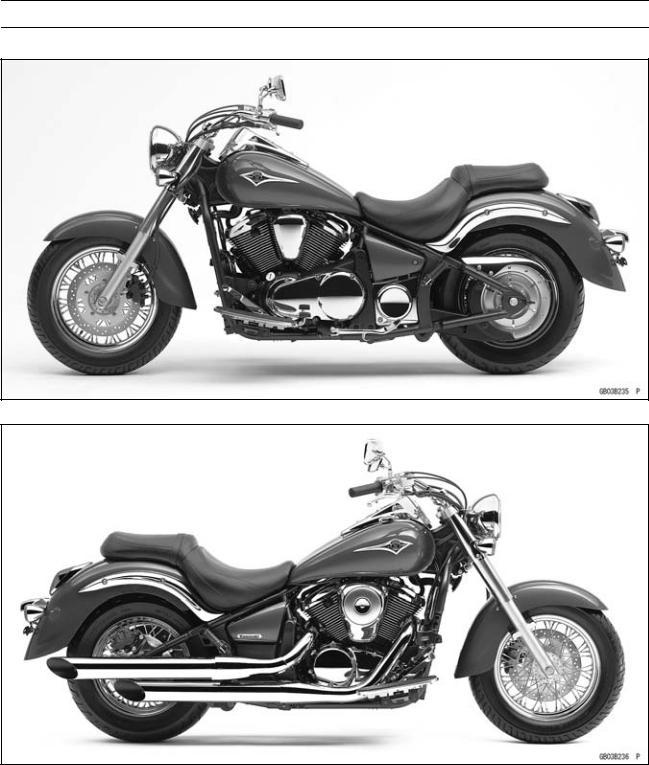
VN900D6F (US and Canada) Left Side View:
VN900D6F (US and Canada) Right Side View:

1-10 GENERAL INFORMATION
General Specifications
|
Items |
VN900B6F/D6F |
|
Dimensions |
|
|
Overall Length |
2 465 mm (97.05 in.) |
|
Overall Width |
1 005 mm (39.57 in.), (AU) 980 mm (38.6 in.) |
|
Overall Height |
|
|
(VN900B) |
1 065 mm (41.93 in.) |
|
(VN900D) |
1 480 mm (58.27 in.) |
|
Wheelbase |
1 645 mm (64.76 in.) |
|
Road Clearance |
135 mm (5.31 in.) |
|
Seat Height |
680 mm (26.8 in.) |
|
Dry Mass |
|
|
(VN900B) |
253 kg (558 lb), (EU) 254 kg (560 lb) |
|
(VN900D) |
270 kg (595 lb) |
|
Curb Mass: |
|
|
Front |
|
|
(VN900B) |
130 kg (287 lb), (EU) 131 kg (289 lb) |
|
(VN900D) |
134 kg (295 lb) |
|
Rear |
|
|
(VN900B) |
151 kg (333 lb) |
|
(VN900D) |
164 kg (362 lb) |
|
Fuel Tank Capacity |
20 L (5.3 US gal) |
|
Performance |
|
|
Minimum Turning Radius |
2.9 m (9.5 ft) |
|
Engine |
|
|
Type |
4-stroke, SOHC, V2-cylinder |
|
Cooling System |
Liquid-cooled |
|
Bore And Stroke |
88.0 × 74.2 mm (3.46 × 2.92 in.) |
|
Displacement |
903 mL (55.1 cu in.) |
|
Compression Ratio |
9.5 : 1 |
|
Maximum Horsepower |
37 kW (50 PS) @5 700 r/min (rpm), (CA) (CAL) (US) – |
|
Maximum Torque |
78 N·m (8.0 kgf·m, 58 ft·lb) @3 700 r/min (rpm), |
|
(CA) (CAL) (US) – |
|
|
Carburetion System |
DFI (Digital Fuel Injection) System |
|
Starting System |
Electric starter |
|
Ignition System |
Battery and coil (transistorized) |
|
Timing Advance |
Electronically advanced (digital) |
|
Ignition Timing |
From 0° BTDC @1 000r/min (rpm) to 53° BTDC @5 800 r/min |
|
(rpm) |
|
|
(AU) From 3.5° BTDC @1 000r/min (rpm) to 53° BTDC |
|
|
@5 800 r/min (rpm) |
|
|
Spark Plugs |
NGK CPR7EA-9 |
|
Cylinder Numbering Method |
Front to Rear, 1-2 |
|
Firing Order |
1-2 |
|
GENERAL INFORMATION 1-11 |
|
|
General Specifications |
|
|
Items |
VN900B6F/D6F |
|
Valve Timing: |
|
|
Inlet |
|
|
open |
40° BTDC |
|
close |
40° ABDC |
|
duration |
260° |
|
Exhaust |
|
|
Open |
55° BBDC |
|
Close |
25° ATDC |
|
Duration |
260° |
|
Lubrication System |
Forced lubrication (wet sump) |
|
Engine Oil: |
|
|
Type |
API SE, SF or SG class |
|
API SH or SJ class with JASO MA |
|
|
Viscosity |
SAE10W-40 |
|
Capacity |
3.7 L (3.9 US qt) |
|
Drive Train |
|
|
Primary Reduction System: |
|
|
Type |
Chain |
|
Reduction Ratio |
2.184 (83/38) |
|
Clutch Type |
Wet multi disc |
|
Transmission: |
|
|
Type |
5-speed, constant mesh, return shift |
|
Gear Ratios: |
|
|
1st |
2.786 (39/14) |
|
2nd |
1.889 (34/18) |
|
3rd |
1.360 (34/25) |
|
4th |
1.107 (31/28) |
|
5th |
0.963 (26/27) |
|
Final Drive System: |
|
|
Type |
Belt |
|
Reduction Ratio |
2.063 (66/32) |
|
Overall Drive Ratio |
4.338 @ Top gear |
|
Frame |
|
|
Type |
Tubular, double cradle |
|
Caster (Rake Angel) |
32° |
|
Trail |
160 mm (6.30 in.) |
|
Front Tire: |
|
|
Type |
Tubeless |
|
Size |
130/90-16M/C 67H |
|
Rim Size |
16M/C × MT3.00 |
|
Rear Tire: |
|
|
Type |
Tubeless |
|
Size |
180/70-15M/C 76H |
|
Rim Size |
15M/C × MT4.50 |

1-12 GENERAL INFORMATION
General Specifications
|
Items |
VN900B6F/D6F |
|
Front Suspension: |
|
|
Type |
Telescopic fork |
|
Wheel Travel |
150 mm (5.90 in.) |
|
Rear Suspension: |
|
|
Type |
Swingarm (uni-trak) |
|
Wheel Travel |
103 mm (4.06 in.) |
|
Brake Type: |
|
|
Front |
Single disc |
|
Rear |
Single disc |
|
Electrical Equipment |
|
|
Battery: |
|
|
Capacity |
12 V 10 Ah |
|
Headlight: |
|
|
Type |
Semi-sealed beam |
|
Bulb |
12 V 60/55W (quartz-halogen) |
|
Tail/brake Light |
12 V 5/21 W |
|
Alternator: |
|
|
Type |
Three-phase AC |
|
Rated Output |
32 A × 14 V @5 000 r/min (rpm) |
Specifications subject to change without notice, and may not apply to every country. AU: Australia
CA: Canada
CAL: California
EU: Europe
US: United States of America
GENERAL INFORMATION 1-13
Unit Conversion Table
Prefixes for Units: |
Units of Length: |
|
Prefix |
Symbol |
Power |
||
|
mega |
M |
× 1 000 |
000 |
|
|
kilo |
k |
× |
1 000 |
|
|
centi |
c |
× |
0.01 |
|
|
milli |
m |
× |
0.001 |
|
|
micro |
||||
|
µ |
× 0.000001 |
Units of Mass:
|
kg |
× |
2.205 |
= |
lb |
|
g |
× |
0.03527 |
= |
oz |
|
km |
× |
0.6214 |
= |
mile |
|
m |
× |
3.281 |
= |
ft |
|
mm |
× |
0.03937 |
= |
in |
Units of Torque:
|
N·m |
× |
0.1020 |
= |
kgf·m |
|
N·m |
× |
0.7376 |
= |
ft·lb |
|
N·m |
× |
8.851 |
= |
in·lb |
|
kgf·m |
× |
9.807 |
= |
N·m |
|
kgf·m |
× |
7.233 |
= |
ft·lb |
|
kgf·m |
× |
86.80 |
= |
in·lb |
Units of Volume: |
Units of Pressure: |
|||||||||
|
kPa |
× |
0.01020 |
= |
kgf/cm² |
||||||
|
L |
× |
0.2642 |
= |
gal (US) |
kPa |
× |
0.1450 |
= |
psi |
|
|
L |
× |
0.2200 |
= |
gal (imp) |
kPa |
× |
0.7501 |
= |
cm Hg |
|
|
L |
× |
1.057 |
= |
qt (US) |
kgf/cm² |
× |
98.07 |
= |
kPa |
|
|
L |
× |
0.8799 |
= |
qt (imp) |
kgf/cm² |
× |
14.22 |
= |
psi |
|
|
L |
× |
2.113 |
= |
pint (US) |
cm Hg |
× |
1.333 |
= |
kPa |
|
|
L |
× |
1.816 |
= |
pint (imp) |
||||||
|
mL |
× |
0.03381 |
= |
oz (US) |
Units of Speed: |
|||||
|
mL |
× |
0.02816 |
= |
oz (imp) |
km/h |
× |
0.6214 |
= |
mph |
|
|
mL |
× |
0.06102 |
= |
cu in |
||||||
Units of Force: |
Units of Power: |
|||||||||
|
kW |
× |
1.360 |
= |
PS |
||||||
|
N |
× |
0.1020 |
= |
kg |
kW |
× |
1.341 |
= |
HP |
|
|
N |
× |
0.2248 |
= |
lb |
||||||
|
PS |
× |
0.7355 |
= |
kW |
||||||
|
kg |
× |
9.807 |
= |
N |
PS |
× |
0.9863 |
= |
HP |
|
|
kg |
× |
2.205 |
= |
lb |
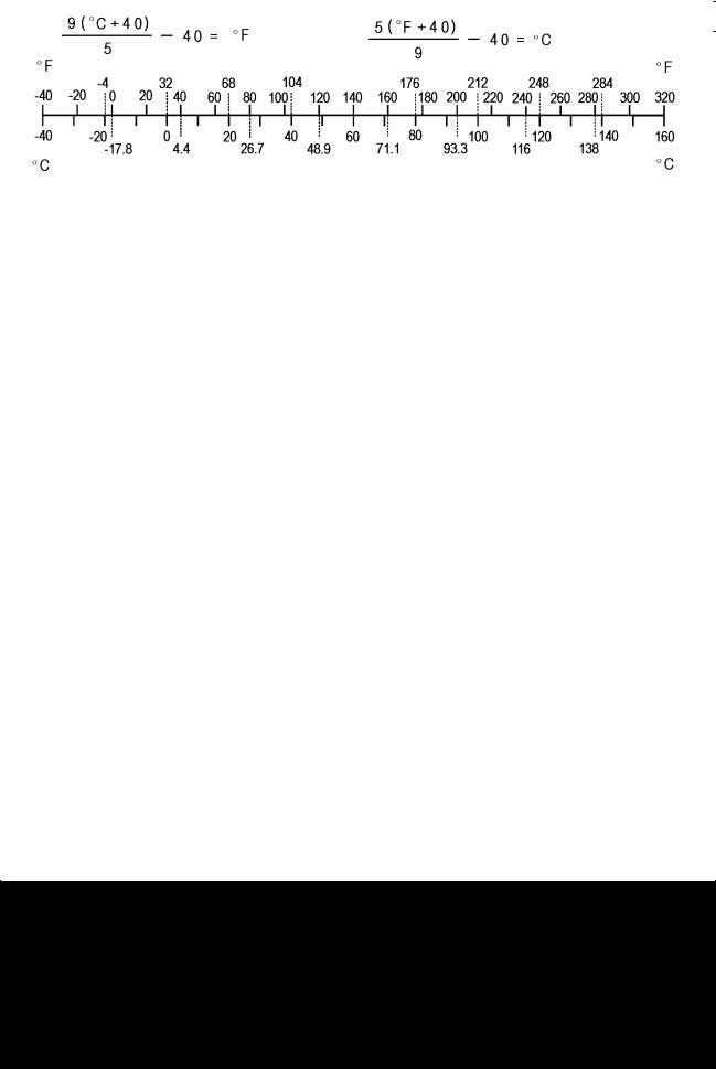
Units of Temperature:

PERIODIC MAINTENANCE 2-1
Periodic Maintenance
Table of Contents
|
Periodic Maintenance Chart ……………………………………………………………………………………… |
2-3 |
||
|
Torque and Locking Agent………………………………………………………………………………………… |
2-6 |
2 |
|
|
Specifications |
2-11 |
||
|
Special Tools ………………………………………………………………………………………………………….. |
2-13 |
||
|
Periodic Maintenance Procedures……………………………………………………………………………… |
2-14 |
||
|
Fuel System (DFI)…………………………………………………………………………………………………. |
2-14 |
||
|
Fuel Hose Inspection (fuel leak, damage, installation condition) ……………………………….. |
2-14 |
||
|
Throttle Control System Inspection……………………………………………………………………….. |
2-14 |
||
|
Idle Speed Inspection …………………………………………………………………………………………. |
2-15 |
||
|
Idle Speed Adjustment………………………………………………………………………………………… |
2-15 |
||
|
Cooling System…………………………………………………………………………………………………….. |
2-16 |
||
|
Coolant Level Inspection……………………………………………………………………………………… |
2-16 |
||
|
Radiator Hose and Pipe Inspection (coolant leak, damage, installation condition) ……… |
2-16 |
||
|
Air Suction System ……………………………………………………………………………………………….. |
2-17 |
||
|
Air Suction System Damage Inspection…………………………………………………………………. |
2-17 |
||
|
Engine Top End ……………………………………………………………………………………………………. |
2-17 |
||
|
Valve Clearance Inspection …………………………………………………………………………………. |
2-17 |
||
|
Valve Clearance Adjustment………………………………………………………………………………… |
2-17 |
||
|
Clutch………………………………………………………………………………………………………………….. |
2-21 |
||
|
Clutch Operation Inspection…………………………………………………………………………………. |
2-21 |
||
|
Wheels and Tires………………………………………………………………………………………………….. |
2-22 |
||
|
Tire Air Pressure Inspection…………………………………………………………………………………. |
2-22 |
||
|
Wheel/Tire Damage Inspection…………………………………………………………………………….. |
2-22 |
||
|
Tire Tread Wear Inspection………………………………………………………………………………….. |
2-22 |
||
|
Wheel Bearing Damage Inspection ………………………………………………………………………. |
2-23 |
||
|
Spoke Tightness and Rim Runout Inspection…………………………………………………………. |
2-24 |
||
|
Drive Train …………………………………………………………………………………………………………… |
2-25 |
||
|
Belt Deflection Inspection ……………………………………………………………………………………. |
2-25 |
||
|
Belt Deflection Adjustment…………………………………………………………………………………… |
2-27 |
||
|
Wheel Alignment Inspection/Adjustment ……………………………………………………………….. |
2-28 |
||
|
Belt Wear and Damage Inspection ……………………………………………………………………….. |
2-28 |
||
|
Brake System ………………………………………………………………………………………………………. |
2-31 |
||
|
Brake Fluid Leak Inspection…………………………………………………………………………………. |
2-31 |
||
|
Brake Hose Damage and Installation Condition Inspection………………………………………. |
2-32 |
||
|
Brake Operation Inspection …………………………………………………………………………………. |
2-32 |
||
|
Brake Fluid Level Inspection………………………………………………………………………………… |
2-32 |
||
|
Brake Pad Wear Inspection …………………………………………………………………………………. |
2-33 |
||
|
Brake Light Switch Operation Inspection ……………………………………………………………….. |
2-33 |
||
|
Suspensions ………………………………………………………………………………………………………… |
2-34 |
||
|
Front Forks/Rear Shock Absorber Operation Inspection ………………………………………….. |
2-34 |
||
|
Front Fork Oil Leak Inspection……………………………………………………………………………… |
2-35 |
||
|
Rear Shock Absorber Oil Leak Inspection ……………………………………………………………… |
2-35 |
||
|
Swingarm Pivot Lubrication …………………………………………………………………………………. |
2-35 |
||
|
Rocker Arm Operation Inspection…………………………………………………………………………. |
2-35 |
||
|
Tie-Rod Operation Inspection ………………………………………………………………………………. |
2-35 |
||
|
Uni-trak Linkage Lubrication ………………………………………………………………………………… |
2-36 |
||
|
Steering System …………………………………………………………………………………………………… |
2-36 |
||
|
Steering Play Inspection ……………………………………………………………………………………… |
2-36 |
||
|
Steering Play Adjustment…………………………………………………………………………………….. |
2-36 |
||
|
Steering Stem Bearing Lubrication ……………………………………………………………………….. |
2-38 |

2-2 PERIODIC MAINTENANCE
|
Electrical System ………………………………………………………………………………………………….. |
2-39 |
|
Lights and Switches Operation Inspection……………………………………………………………… |
2-39 |
|
Headlight Aiming Inspection ………………………………………………………………………………… |
2-41 |
|
Sidestand Switch Operation Inspection …………………………………………………………………. |
2-42 |
|
Engine Stop Switch Operation Inspection………………………………………………………………. |
2-43 |
|
Others…………………………………………………………………………………………………………………. |
2-44 |
|
Chassis Parts Lubrication ……………………………………………………………………………………. |
2-44 |
|
Bolts, Nuts and Fasteners Tightness Inspection……………………………………………………… |
2-45 |
|
Evaporative Emission Control SystemInspection (CAL)……………………………………………… |
2-46 |
|
Evaporative Emission Control System Inspection …………………………………………………… |
2-46 |
|
Replacement Parts ……………………………………………………………………………………………….. |
2-47 |
|
Air Cleaner Element Replacement………………………………………………………………………… |
2-47 |
|
Engine Oil Change……………………………………………………………………………………………… |
2-48 |
|
Oil Filter Replacement ………………………………………………………………………………………… |
2-49 |
|
Fuel Hose Replacement ……………………………………………………………………………………… |
2-49 |
|
Coolant Change…………………………………………………………………………………………………. |
2-51 |
|
Radiator Hose and O-ring Replacement………………………………………………………………… |
2-53 |
|
Brake Hose Replacement ……………………………………………………………………………………. |
2-53 |
|
Brake Fluid Change ……………………………………………………………………………………………. |
2-54 |
|
Master Cylinder Rubber Parts Replacement ………………………………………………………….. |
2-56 |
|
Caliper Rubber Parts Replacement ………………………………………………………………………. |
2-57 |
|
Spark Plug Replacement …………………………………………………………………………………….. |
2-60 |
PERIODIC MAINTENANCE 2-3
Periodic Maintenance Chart
The scheduled maintenance must be done in accordance with this chart to keep the motorcycle in good running condition.The initial maintenance is vitally important and must not be neglected.
Periodic Inspection
|
FREQUENCY |
Whichever |
* ODOMETER READING |
||||||||||||
|
comes |
× 1 000 km |
See |
||||||||||||
|
first |
(× 1 000 mile) |
|||||||||||||
|
Page |
||||||||||||||
|
1 |
6 |
12 |
18 |
24 |
30 |
36 |
||||||||
|
INSPECTION |
Every |
(0.6) |
(4) |
(7.5) |
(12) |
(15) |
(20) |
(24) |
||||||
|
Fuel System |
||||||||||||||
|
Throttle control system (play, smooth |
year |
• |
• |
• |
• |
2-14 |
||||||||
|
return, no drag) — inspect |
||||||||||||||
|
Idle speed — inspect |
• |
• |
• |
• |
2-15 |
|||||||||
|
Fuel leak (fuel hose and pipe) — inspect |
year |
• |
• |
• |
• |
2-14 |
||||||||
|
Fuel hose — inspect |
year |
• |
• |
• |
• |
2-14 |
||||||||
|
Fuel hoses installation condition — inspect |
year |
• |
• |
• |
• |
2-14 |
||||||||
|
Cooling System |
||||||||||||||
|
Coolant level — inspect |
• |
• |
• |
• |
2-16 |
|||||||||
|
Coolant leak (radiator hose and pipe) — |
year |
• |
• |
• |
• |
2-16 |
||||||||
|
inspect |
||||||||||||||
|
Radiator hose damage — inspect |
year |
• |
• |
• |
• |
2-16 |
||||||||
|
Radiator hose installation condition — |
year |
• |
• |
• |
• |
2-16 |
||||||||
|
inspect |
||||||||||||||
|
Air Suction System |
||||||||||||||
|
Air suction system damage — inspect |
• |
• |
• |
2-17 |
||||||||||
|
Evaporative Emission Control System |
||||||||||||||
|
(CAL) |
||||||||||||||
|
Evaporative emission control system |
• |
• |
• |
• |
• |
• |
• |
2-46 |
||||||
|
function — inspect |
||||||||||||||
|
Engine Top End |
||||||||||||||
|
Valve clearance — inspect (US and CA) |
• |
2-17 |
||||||||||||
|
Valve clearance — inspect (EU and AU) |
Every 42 000 km (26 000 mile) |
2-17 |
||||||||||||
|
Clutch |
||||||||||||||
|
Clutch operation (play, disengagement, |
• |
• |
• |
• |
2-21 |
|||||||||
|
engagement) — inspect |
||||||||||||||
|
Wheels and Tires |
||||||||||||||
|
Tire air pressure — inspect |
year |
• |
• |
• |
2-22 |
|||||||||
|
Wheel/tire damage — inspect |
• |
• |
• |
2-22 |
||||||||||
|
Tire tread wear, abnormal wear — inspect |
• |
• |
• |
2-22 |
||||||||||
|
Wheel bearings damage — inspect |
year |
• |
• |
• |
2-23 |
|||||||||
|
Spoke tightness and rim runout-inspect |
• |
• |
• |
• |
• |
• |
• |
2-24 |
||||||
|
Drive Train |
||||||||||||||
|
Belt deflection — inspect |
• |
• |
• |
• |
• |
• |
• |
2-25 |
||||||
|
Belt wear and damage — inspect |
• |
• |
• |
• |
• |
• |
• |
2-28 |
||||||
|
Brake System |
||||||||||||||
|
Brake fluid leak — inspect |
year |
• |
• |
• |
• |
• |
• |
• |
2-31 |
2-4 PERIODIC MAINTENANCE
Periodic Maintenance Chart
|
FREQUENCY |
Whichever |
* ODOMETER READING |
||||||||||||
|
comes |
× 1 000 km |
See |
||||||||||||
|
first |
(× 1 000 mile) |
|||||||||||||
|
Page |
||||||||||||||
|
1 |
6 |
12 |
18 |
24 |
30 |
36 |
||||||||
|
INSPECTION |
Every |
(0.6) |
(4) |
(7.5) |
(12) |
(15) |
(20) |
(24) |
||||||
|
Brake hose damage — inspect |
year |
• |
• |
• |
• |
• |
• |
• |
2-32 |
|||||
|
Brake hose installation condition — inspect |
year |
• |
• |
• |
• |
• |
• |
• |
2-32 |
|||||
|
Brake operation (effectiveness, play, no |
year |
• |
• |
• |
• |
• |
• |
• |
2-32 |
|||||
|
drag) — inspect |
||||||||||||||
|
Brake fluid level — inspect |
6 months |
• |
• |
• |
• |
• |
• |
• |
2-32 |
|||||
|
Brake pad wear — inspect # |
• |
• |
• |
• |
• |
• |
2-33 |
|||||||
|
Brake light switch operation — inspect |
• |
• |
• |
• |
• |
• |
• |
2-33 |
||||||
|
Suspensions |
||||||||||||||
|
Front forks/rear shock absorber operation |
• |
• |
• |
2-34 |
||||||||||
|
(damping and smooth stroke) — inspect |
||||||||||||||
|
Front forks/rear shock absorber oil leak — |
year |
• |
• |
• |
2-35 |
|||||||||
|
inspect |
||||||||||||||
|
Swingarm pivot — lubricate |
• |
2-35 |
||||||||||||
|
Uni — trak rocker arm operation — inspect |
• |
• |
• |
2-35 |
||||||||||
|
Uni — trak tie rod operation — inspect |
• |
• |
• |
2-35 |
||||||||||
|
Uni — trak rocker arm bearings — lubricate |
• |
2-36 |
||||||||||||
|
Uni — trak tie rod bearings — lubricate |
• |
2-36 |
||||||||||||
|
Steering System |
||||||||||||||
|
Steering play — inspect |
year |
• |
• |
• |
• |
2-35 |
||||||||
|
Steering stem bearings — lubricate |
2 years |
• |
2-38 |
|||||||||||
|
Electrical System |
||||||||||||||
|
Lights and switches operation — inspect |
year |
• |
• |
• |
2-39 |
|||||||||
|
Headlight aiming — inspect |
year |
• |
• |
• |
2-41 |
|||||||||
|
Sidestand switch operation — inspect |
year |
• |
• |
• |
2-42 |
|||||||||
|
Engine stop switch operation — inspect |
year |
• |
• |
• |
2-43 |
|||||||||
|
Others |
||||||||||||||
|
Chassis parts — lubricate |
year |
• |
• |
• |
2-44 |
|||||||||
|
Bolts and nuts tightness — inspect |
• |
• |
• |
• |
2-45 |
#: Service more frequently when operating in severe conditions; dusty, wet, muddy, high speed or frequent starting/stopping.
*: For higher odometer readings, repeat at the frequency interval established here.
(AU): Australia
(CA): Canada (CAL):California (EU): Europe (US): United States
PERIODIC MAINTENANCE 2-5
Periodic Maintenance Chart
Periodic Replacement Parts
|
FREQUENCY |
Whichever |
* ODOMETER READING |
|||||||||
|
comes |
× 1 000 km |
See |
|||||||||
|
first |
(× 1 000 mile) |
||||||||||
|
Page |
|||||||||||
|
1 |
12 |
24 |
36 |
48 |
|||||||
|
CHANGE/REPLACE ITEM |
Every |
(0.6) |
(7.5) |
(15) |
(24) |
(30) |
|||||
|
Air cleaner element # |
Every 18 000 km (12 000 mile) |
2-47 |
|||||||||
|
Engine oil # |
year |
• |
• |
• |
• |
• |
2-48 |
||||
|
Oil filter |
year |
• |
• |
• |
• |
• |
2-49 |
||||
|
Fuel hose |
4 years |
• |
2-49 |
||||||||
|
Coolant |
3 years |
• |
2-51 |
||||||||
|
Radiator hoses and O-rings |
3 years |
• |
2-53 |
||||||||
|
Brake hoses |
4 years |
• |
2-53 |
||||||||
|
Brake fluid (Front and Rear) |
2 years |
• |
• |
2-54 |
|||||||
|
Rubber parts of master cylinder and caliper |
4 years |
• |
2-57 |
||||||||
|
Spark plug |
• |
• |
• |
• |
2-60 |
#: Service more frequently when operating in severe conditions; dusty, wet, muddy, high speed or frequent starting/stopping.
*: For higher odometer readings, repeat at the frequency interval established here.

2-6 PERIODIC MAINTENANCE
Torque and Locking Agent
The following tables list the tightening torque for the major fasteners requiring use of a non-permanent locking agent or liquid gasket.
Letters used in the “Remarks” column mean: 2T: Apply 2-stroke oil.
L:Apply a non-permanent locking agent to the threads. Lh: Left-hand threads
M:Apply molybdenum disulfide grease.
MO: Apply molybdenum disulfide oil solution.
(mixture of the engine oil and molybdenum disulfide grease in a weight ratio 10 : 1) S: Tighten the fasteners following the specified sequence.
Si: Apply silicone grease (ex. PBC grease). SS: Apply silicone sealant.
|
Fastener |
Torque |
Remarks |
||||
|
N·m |
kgf·m |
ft·lb |
||||
|
Fuel System |
||||||
|
Water Temperature Sensor |
12 |
1.2 |
106 in·lb |
|||
|
Speed Sensor Mounting Bolt |
9.8 |
1.0 |
87 in·lb |
L |
||
|
Fuel Pump Bolts |
9.8 |
1.0 |
87 in·lb |
L |
||
|
Oxygen Sensor |
25 |
2.5 |
18 |
|||
|
Fuel Level Sensor Mounting Bolts |
6.9 |
0.70 |
61 in·lb |
L |
||
|
Air Cleaner Housing Bolts |
9.8 |
1.0 |
87 |
in·lb |
||
|
Air Cleaner Cover Bolts |
4.9 |
0.50 |
43 in·lb |
|||
|
Air Cleaner Element Screw |
4.9 |
0.50 |
43 in·lb |
|||
|
Throttle Body Assy Holder Bolts |
9.8 |
1.0 |
87 in·lb |
|||
|
Inlet Manifold Bolts |
9.8 |
1.0 |
87 |
in·lb |
L |
|
|
Delivery Joint Bolts |
9.8 |
1.0 |
87 |
in·lb |
L |
|
|
Delivery Joint Bracket Bolts |
9.8 |
1.0 |
87 |
in·lb |
||
|
Vehicle-down Sensor Bolts |
4.9 |
0.50 |
43 in·lb |
|||
|
Inlet Air Pressure Sensor Bolt |
6.9 |
0.70 |
61 |
in·lb |
||
|
Inlet Air Temperature Sensor Screw |
1.2 |
0.12 |
11 in·lb |
|||
|
Cooling System |
||||||
|
Radiator Hose Clamp Screws |
2.0 |
0.20 |
18 in·lb |
|||
|
Water Pump Impeller Bolt |
9.8 |
1.0 |
87 in·lb |
|||
|
Coolant Drain Bolt |
9.8 |
1.0 |
87 |
in·lb |
||
|
Thermostat Housing Cover Bracket Bolts |
6.9 |
0.70 |
61 in·lb |
|||
|
Thermostat Housing Cover Bolts |
4.9 |
0.50 |
43 in·lb |
L |
||
|
Radiator Bolts |
6.9 |
0.70 |
61 |
in·lb |
||
|
Radiator Screen Screws |
6.9 |
0.70 |
61 in·lb |
|||
|
Radiator Fan Bolts |
8.3 |
0.85 |
73 in·lb |
|||
|
Water Hose Fitting Bolts |
9.8 |
1.0 |
87 |
in·lb |
||
|
Reserve Tank Bolts |
6.9 |
0.70 |
61 in·lb |
|||
|
Engine Top End |
||||||
|
Cylinder Head nuts (M10) (First) |
20 |
2.0 |
15 |
MO, S |
||
|
Cylinder Head nuts (M10) (Final) |
49 |
5.0 |
36 |
MO, S |
||
|
Cylinder Head nuts (M8) |
25 |
2.5 |
18 |
S |
||
|
Camshaft Cap Bolts |
25 |
2.5 |
18 |
![]()
PERIODIC MAINTENANCE 2-7
Torque and Locking Agent
|
Fastener |
Torque |
Remarks |
|||
|
N·m |
kgf·m |
ft·lb |
|||
|
Cylinder Head Cover Bolts |
12 |
1.2 |
106 in·lb |
||
|
Cylinder Head Outer Cover Bolts |
9.8 |
1.0 |
87 in·lb |
||
|
Plug (PT1/4) |
15 |
1.5 |
11 |
L |
|
|
Plug (PT1/2) |
20 |
2.0 |
15 |
L |
|
|
Muffler Mounting Bolts |
25 |
2.5 |
18 |
||
|
Muffler Mounting Nut |
25 |
2.5 |
18 |
||
|
Muffler Joint Clamp Bolt |
17 |
1.7 |
12 |
||
|
Exhaust Pipe Cover Clamp Bolts |
6.9 |
0.70 |
61 in·lb |
||
|
Exhaust Pipe Cover Bolts |
6.9 |
0.70 |
61 in·lb |
||
|
Exhaust Pipe Holder Nuts |
17 |
1.7 |
12 |
||
|
Camshaft Sprocket Bolts |
49 |
5.0 |
36 |
L |
|
|
Camshaft Chain Tensioner Cap Bolts |
20 |
2.0 |
15 |
||
|
Camshaft Chain Guide Bolts |
9.8 |
1.0 |
87 in·lb |
L |
|
|
Clutch |
|||||
|
Right Engine Cover Mounting Bolts |
9.8 |
1.0 |
87 in·lb |
L (1) |
|
|
Clutch Spring Bolts |
9.8 |
1.0 |
87 in·lb |
||
|
Clutch Hub Nut |
130 |
13.2 |
95.9 |
||
|
Clutch Lever Clamp Bolts |
7.8 |
0.80 |
69 in·lb |
S |
|
|
Engine Lubrication |
|||||
|
Engine Oil Drain Plug |
20 |
2.0 |
15 |
||
|
Oil Pump Cover Bolt |
9.8 |
1.0 |
87 in·lb |
L |
|
|
Oil Pump Drive Chain Guide Bolt |
9.8 |
1.0 |
87 in·lb |
L |
|
|
Oil Filter Plate Bolts |
7.8 |
0.80 |
69 in·lb |
||
|
Oil Pressure Switch |
15 |
1.5 |
11 |
SS |
|
|
Oil Pipe Bolts |
9.8 |
1.0 |
87 in·lb |
L |
|
|
Oil Return Pipe Bolts |
9.8 |
1.0 |
87 in·lb |
||
|
Oil Pressure Switch Adapter |
20 |
2.0 |
15 |
||
|
Oil Filter |
18 |
1.8 |
13 |
||
|
Oil Screen Plug |
20 |
2.0 |
15 |
||
|
Oil Pressure Relief Valve |
15 |
1.5 |
11 |
L |
|
|
Engine Removal/Installation |
|||||
|
Engine Mounting Nuts |
44 |
4.5 |
32 |
||
|
Engine Mounting Bracket Bolts (M10) |
44 |
4.5 |
32 |
||
|
Engine Mounting Bracket Bolts (M8) |
25 |
2.5 |
18 |
||
|
Downtube Bolts |
44 |
4.5 |
32 |
||
|
Crankshaft/Transmission |
|||||
|
Balancer Gear Bolt |
69 |
7.0 |
51 |
||
|
Starter Motor Clutch Gear Bolt |
69 |
7.0 |
51 |
||
|
Primary Gear Bolt |
98 |
10 |
72 |
MO |
|
|
Connecting Rod Big End Bolts |
46 |
4.7 |
34 |
MO |
|
|
Shift Drum Bearing Stopper Bolts |
9.8 |
1.0 |
87 in·lb |
L |
|
|
Shift Drum Cam Bolt |
12 |
1.2 |
106 in·lb |
L |
|
|
Neutral Switch |
15 |
1.5 |
11 |

2-8 PERIODIC MAINTENANCE
Torque and Locking Agent
|
Fastener |
Torque |
Remarks |
||||
|
N·m |
kgf·m |
ft·lb |
||||
|
Rear Shift Lever Clamp Bolt |
12 |
1.2 |
106 in·lb |
|||
|
Shift Pedal Clamp Bolt |
12 |
1.2 |
106 in·lb |
|||
|
Shift Rod Locknut (Front) |
9.8 |
87 in·lb |
||||
|
1.0 |
||||||
|
Oil Nozzle |
3.9 |
0.40 |
34 in·lb |
|||
|
Shift Rod Locknut (Rear) |
9.8 |
1.0 |
87 in·lb |
Lh |
||
|
Rear Shift Pedal Pad Screw |
6.9 |
0.70 |
61 in·lb |
|||
|
Shift Drum Position Lever Bolt |
9.8 |
1.0 |
87 in·lb |
|||
|
Shift Shaft Return Spring Pin |
29 |
3.0 |
21 |
L |
||
|
Bearing Retainer Bolts |
9.8 |
1.0 |
87 in·lb |
L |
||
|
Balancer Shaft Bearing Stopper Plate Bolts |
9.8 |
1.0 |
87 in·lb |
|||
|
Crankcase Bolts (M10) |
39 |
4.0 |
29 |
S |
||
|
Crankcase Bolts (M6) |
9.8 |
1.0 |
87 in·lb |
S |
||
|
Engine Ground Lead Bolt |
9.8 |
1.0 |
87 in·lb |
|||
|
Clamp Mounting Bolts |
9.8 |
1.0 |
87 in·lb |
|||
|
External Shift Mechanism Cover Bolts |
9.8 |
1.0 |
87 in·lb |
|||
|
Wheels/Tires |
||||||
|
Front Axle Nut |
108 |
11.0 |
79.7 |
|||
|
Front Axle Clamp Bolt |
20 |
2.0 |
15 |
|||
|
Rear Axle Nut |
108 |
11.0 |
79.7 |
|||
|
Spoke Nipples |
5.2 |
0.53 |
46 in·lb |
|||
|
Final Drive |
||||||
|
Rear Pulley Mounting Nuts |
59 |
6.0 |
44 |
|||
|
Rear Pully Plate Bolts |
6.9 |
0.70 |
61 in·lb |
L |
||
|
Engine Pully Mounting Nut |
127 |
13.0 |
93.7 |
M |
||
|
Engine Pullly Plate Bolts |
9.8 |
1.0 |
87 in·lb |
|||
|
Engine Pulley Cover Bolts |
9.8 |
1.0 |
87 in·lb |
|||
|
Engine Pulley Cover Clamp Mounting Bolt |
9.8 |
1.0 |
87 in·lb |
|||
|
Drive Belt Guide Bolts |
9.8 |
1.0 |
87 in·lb |
|||
|
Brakes |
||||||
|
Bleed Valves |
7.8 |
0.80 |
69 in·lb |
|||
|
Brake Hose Banjo Bolts |
25 |
2.5 |
18 |
|||
|
Brake Lever Pivot Bolt |
1.0 |
0.10 |
88 in·lb |
Si |
||
|
Brake Lever Pivot Locknut |
5.9 |
0.60 |
52 in·lb |
|||
|
Brake Pedal Clamp Bolt |
25 |
2.5 |
18 |
|||
|
Front Brake Disc Mounting Bolts |
27 |
2.8 |
20 |
L |
||
|
Front Brake Light Switch Screw |
11 in·lb |
|||||
|
1.2 |
0.12 |
|||||
|
Front Brake Reservoir Cap Screws |
1.5 |
0.15 |
13 in·lb |
|||
|
Front Caliper Mounting Bolts |
34 |
3.5 |
25 |
|||
|
Front Master Cylinder Clamp Bolts |
8.8 |
0.90 |
78 in·lb |
S |
||
|
Rear Brake Disc Mounting Bolts |
27 |
2.8 |
20 |
L |
||
|
Rear Caliper Mounting Bolts |
34 |
3.5 |
25 |
|||
|
Rear Master Cylinder Mounting Bolts |
25 |
2.5 |
18 |
|||
|
Rear Master Cylinder Push Rod Locknut |
17 |
1.7 |
12 |

PERIODIC MAINTENANCE 2-9
Torque and Locking Agent
|
Fastener |
Torque |
Remarks |
|||
|
N·m |
kgf·m |
ft·lb |
|||
|
Suspension |
|||||
|
Swingarm Pivot Shaft Nut |
98 |
10 |
72 |
||
|
Rear Shock Absorber Nuts |
59 |
6.0 |
44 |
||
|
Lower Tie-Rod Nut |
59 |
6.0 |
44 |
||
|
Upper Tie-Rod Nut |
108 |
11.0 |
80 |
||
|
Rocker Arm Pivot Shaft Nut |
59 |
6.0 |
44 |
||
|
Upper Front Fork Clamp Bolts |
20 |
2.0 |
15 |
||
|
Lower Front Fork Clamp Bolts |
34 |
3.5 |
25 |
||
|
Front Fork Bottom Allen Bolts |
20 |
2.0 |
15 |
L |
|
|
Front Fork Upper Cover Stopper Bolts |
4.2 |
0.43 |
37 in·lb |
||
|
Steering |
|||||
|
Handlebar Holder Nuts |
34 |
3.5 |
25 |
||
|
Handlebar Clamp Bolts |
34 |
3.5 |
25 |
S, 2T |
|
|
Steering Stem Head Bolt |
49 |
5.0 |
36 |
||
|
Steering Stem Nut |
4.9 |
0.50 |
43 in·lb |
||
|
Frame |
|||||
|
Sidestand Mounting Nut |
44 |
4.5 |
32 |
||
|
Sidestand Mounting Bolt |
44 |
4.5 |
32 |
||
|
Footboard Bracket Bolts |
34 |
3.5 |
25 |
||
|
Left Footpeg Bracket Bolts |
25 |
2.5 |
18 |
||
|
Right Footpeg Bracket Bolts |
25 |
2.5 |
18 |
||
|
Lower Muffler Bracket Bolts |
34 |
3.5 |
25 |
||
|
Upper Muffler Bracket Bolts |
34 |
3.5 |
25 |
||
|
Electrical System |
|||||
|
Alternator Outer Cover Bolts |
9.8 |
1.0 |
87 in·lb |
||
|
Tail/Brake Light Unit Mounting Nuts |
5.9 |
0.60 |
52 in·lb |
||
|
Alternator Cover Bolts |
9.8 |
1.0 |
87 in·lb |
||
|
Timing Inspection Plate Bolts |
9.8 |
1.0 |
87 in·lb |
||
|
Alternator Lead Holder Plate Bolts |
5.9 |
0.60 |
52 in·lb |
||
|
Stator Coil Bolts |
12 |
1.2 |
106 in·lb |
L |
|
|
Alternator Rotor Bolt (First) |
69 |
7.0 |
51 |
S |
|
|
Alternator Rotor Bolt (Final) |
160 |
16.3 |
118 |
S, MO |
|
|
Regulator/Rectifier Bolts |
6.9 |
0.70 |
61 in·lb |
||
|
Starter Motor Mounting Bolts |
9.8 |
1.0 |
87 in·lb |
||
|
Starer Relay Terminal Screws |
3.9 |
0.40 |
34 in·lb |
||
|
Starter Motor Cable Terminal Nut |
5.9 |
0.60 |
52 in·lb |
||
|
Starter Motor Terminal Locknut |
11 |
1.1 |
97 in·lb |
||
|
Starter Motor Through Bolts |
4.9 |
0.50 |
43 in·lb |
||
|
Headlight Rim Screws |
2.9 |
0.30 |
26 in·lb |
L |
|
|
Crankshaft Sensor Bolts |
5.9 |
0.60 |
52 in·lb |
||
|
Ignition Coil Bracket Bolt |
9.8 |
1.0 |
87 in·lb |
||
|
Ignition Coil Mounting Nuts |
6.9 |
0.70 |
61 in·lb |
||
|
Fuel Level Sensor Mounting Bolts |
6.9 |
0.70 |
61 in·lb |

2-10 PERIODIC MAINTENANCE
Torque and Locking Agent
|
Fastener |
Torque |
Remarks |
|||
|
N·m |
kgf·m |
ft·lb |
|||
|
Spark Plugs |
18 |
1.8 |
13 in·lb |
||
|
Sidestand Switch Mounting Bolts |
8.8 |
0.90 |
78 in·lb |
L |
The table below, relating tightening torque to thread diameter, lists the basic torque for the bolts and nuts. Use this table for only the bolts and nuts which do not require a specific torque value. All of the values are for use with dry solvent-cleaned threads.
Basic Torque for General Fasteners
|
Threads Diameter |
Torque |
||||||||
|
(mm) |
N·m |
kgf·m |
ft·lb |
||||||
|
5 |
3.4 |
4.9 |
0.35 |
0.50 |
30 |
43 in·lb |
|||
|
6 |
5.9 |
7.8 |
0.60 |
0.80 |
52 |
69 in·lb |
|||
|
8 |
14 |
19 |
1.4 |
1.9 |
10.0 |
13.5 |
|||
|
10 |
25 |
34 |
2.6 |
3.5 |
19.0 |
25 |
|||
|
12 |
44 |
61 |
4.5 |
6.2 |
33 |
45 |
|||
|
14 |
73 |
98 |
7.4 |
10.0 |
54 |
72 |
|||
|
16 |
115 |
155 |
11.5 |
16.0 |
83 |
115 |
|||
|
18 |
165 |
225 |
17.0 |
23.0 |
125 |
165 |
|||
|
20 |
225 |
325 |
23.0 |
33.0 |
165 |
240 |
|
PERIODIC MAINTENANCE 2-11 |
||||
|
Specifications |
||||
|
Item |
Standard |
Service Limit |
||
|
Fuel System |
||||
|
Throttle Grip Free Play |
2 3 mm (0.08 0.12 in.) |
– – – |
||
|
Idle Speed |
1 000 ±50 r/min (rpm) |
– – – |
||
|
Air Cleaner Element |
Polyurethane Foam |
– – – |
||
|
Cooling System |
||||
|
Coolant: |
||||
|
Type (recommended) |
Permanent type of antifreeze |
– – – |
||
|
Color |
Green |
– – – |
||
|
Mixed Ratio |
Soft water 50%, Coolant 50% |
– – – |
||
|
Freezing Point |
–35°C (–31°F) |
– – – |
||
|
Total Amount |
2.2 L (2.3 US qt) |
– – – |
||
|
Engine Top End |
||||
|
Valve Clearance: |
||||
|
Exhaust |
0.20 |
0.25 mm (0.0079 |
0.0098 in.) |
– – – |
|
Inlet |
0.10 |
0.15 mm (0.0039 |
0.0059 in.) |
– – – |
|
Clutch |
||||
|
Clutch Lever Free Play |
2 3 mm (0.08 0.12 in.) |
– – – |
||
|
Engine Lubrication System |
||||
|
Engine Oil: |
||||
|
Type |
API SE, SF or SG |
– – – |
||
|
API SH, SJ or SL with JASO MA |
||||
|
Viscosity |
SAE 10W-40 |
– – – |
||
|
Capacity |
3.0 L (3.2 US qt) (when filter is not |
– – – |
||
|
removed) |
||||
|
3.2 L (3.4 US qt) (when filter is removed) |
– – – |
|||
|
3.7 L (3.9 US qt) (when engine is |
– – – |
|||
|
completely dry) |
||||
|
Level |
Between upper and lower level lines |
– – – |
||
|
(after idling or running) |
||||
|
Wheels/Tires |
||||
|
Tread Depth: |
||||
|
Front |
4.5 mm (0.18 in.) |
1 mm (0.04 in.), |
||
|
(AT, CH, DE) |
||||
|
1.6 mm (0.06 in.) |
||||
|
Rear |
7.4 mm (0.29 in.) |
Up to 130 km/h (80 mph): |
||
|
2 mm (0.08 in.), |
||||
|
Over 130 km/h (80 mph): |
||||
|
3 mm (0.1 in.) |
||||
|
Air Pressure (when Cold): |
||||
|
Front |
Up to 180 kg (397 lb) load: |
– – – |
||
|
200 kPa (2.00 kgf/cm², 28 psi) |
||||
|
Rear |
Up to 97.5 kg (215 lb) load: |
– – – |
||
|
200 kPa (2.00 kgf/cm², 28 psi) |
||||
|
97.5 |
180 kg (215 397 lb) load: |
|||
|
225 kPa (2.25 kgf/cm², 32 psi) |

2-12 PERIODIC MAINTENANCE
Specifications
|
Item |
Standard |
Service Limit |
|
|
Final Drive |
|||
|
Drive Belt Deflection: |
– – – |
||
|
(45 N, 4.6 kgf, 10 lb fprce) |
1.5 4.0 mm (0.059 |
0.16 in.) |
– – – |
|
When Installing New Belt |
1.5 mm (0.059 in.) |
– – – |
|
|
or Engine Remounted |
|||
|
Brakes |
|||
|
Brake Fluid: |
|||
|
Grade |
DOT4 |
– – – |
|
|
Brake Pad Lining |
|||
|
Thickness: |
|||
|
Front |
4.5 mm (0.18 in.) |
1 mm (0.04 in.) |
|
|
Rear |
7.0 mm (0.28 in.) |
1 mm (0.04 in.) |
|
|
Brake Light Timing: |
|||
|
Front |
Pulled ON |
– – – |
|
|
Rear |
ON after about 10 mm (0.39 in.) of |
– – – |
|
|
pedal travel |
|||
|
Electrical System |
|||
|
Spark Plug Gap |
0.8 0.9 mm (0.03 |
0.04 in.) |
– – – |
|
AT: Austria |
|||
|
CH: Switzerland |
|||
|
DE: Germany |

PERIODIC MAINTENANCE 2-13
Special Tools
Inside Circlip Pliers: 57001-143
Oil Filter Wrench: 57001-1249
Steering Stem Nut Wrench: 57001-1100
Spark Plug Wrench, Hex 16: 57001-1262
|
Jack: |
Tension Gauge: |
|
|
57001-1238 |
57001-1585 |
|

2-14 PERIODIC MAINTENANCE
Periodic Maintenance Procedures
Fuel System (DFI)
Fuel Hose Inspection (fuel leak, damage, installation condition)
○The fuel hose is designed to be used throughout the motorcycle’s life without any maintenance. However, if the motorcycle is not properly handled, the high pressure inside the fuel line can cause fuel to leak [A] or the hose to burst. Remove the fuel tank (see Fuel Tank Removal in the Fuel System (DFI) chapter) and check the fuel hose.  Replace the fuel hose if any fraying, cracks [B] or bulges
[C] are noticed.
•Check that the hoses are routed according to Cable, Wire and Hose Routing section in the Appendix chapter.
 Replace the hose if it has been sharply bent or kinked. Hose Joints [A]
Fuel Hose [B]
•Check that the hose joints are securely connected. ○Push and pull [A] the hose joint [B] back and forth more
than two times, and make sure it is locked.  If it does not locked, reinstall the hose joint.

 WARNING
Make sure the hose joint is installed correctly on the delivery pipe by sliding the joint, or the fuel could leak.
Throttle Control System Inspection
•Check the throttle grip free play [A].
 If the free play is incorrect, adjust the throttle cable.
Throttle Grip Free Play
Standard: 2 3 mm (0.08 0.12 in.)
•Check that the throttle grip moves smoothly from close to full open, and the throttle closes quickly and completely in all steering positions by the return spring.
 If the throttle grip doesn’t return properly, check the throttle cable routing, grip free play, and cable damage. Then lubricate the throttle cable.
•Run the engine at the idle speed, and turn the handlebar all the way to the right and left to ensure that the idle speed doesn’t change.
 If the idle speed increases, check the throttle grip free play and the cable routing.

PERIODIC MAINTENANCE 2-15
Periodic Maintenance Procedures
•If necessary, adjust the throttle cable as follows: ○Loosen the locknuts [A] and screw the adjusters [B] all the
way in so as to give the throttle grip plenty of play. ○Turn out the adjuster of the decelerator cable [D] until
there is no play.
○Tighten the locknut against the adjuster.
○Turn the adjuster of the accelerator cable [C] until the proper amount of throttle grip free play is obtained and tighten the locknut against the adjuster.
Idle Speed Inspection
•Start the engine and warm it up thoroughly.
○At first the engine will run fast to decrease warm up time (fast idle).
○Gradually the fast idle will lower to a certain RPM automatically. This is the idle speed.
•Check the idle speed.
Idle Speed |
|
|
Standard: |
1 000 ±50 r/min (rpm) |
•With the engine idling, turn the handlebar to both sides.  If handlebar movement changes the idle speed, the throttle cables may be improperly adjusted or incorrectly routed or damaged. Be sure to correct any of these conditions before riding (see Cable, Wire and Hose Routing section in the Appendix chapter).

 WARNING
Operation with improperly adjusted, incorrectly routed or damaged cables could result in an unsafe riding condition.
 If the idle speed is out of the specified range, adjust it.
Idle Speed Adjustment
•Start the engine and warm it up thoroughly. ○Wait until fast idle speed lowers to a certain value.
•Turn the adjusting screw [A] until the idle speed is correct. ○Open and close the throttle a few times to make sure that the idle speed is within the specified range. Readjust if
necessary. Front [B]

2-16 PERIODIC MAINTENANCE
Periodic Maintenance Procedures
Cooling System
Coolant Level Inspection
NOTE
○Check the level when the engine is cold (room or ambient temperature).
•Check the coolant level in the reserve tank [A] with the motorcycle held upright.
 If the coolant level is lower than the “L” level line [B], remove the reserve tank cover and unscrew the reserve tank cap, and add coolant to the “F” level line [C].
“L”: low “F”: full
CAUTION
For refilling, add the specified mixture of coolant and soft water. Adding water alone dilutes the coolant and degrades its anticorrosion properties. The diluted coolant can attack the aluminum engine parts. In an emergency, soft water alone can be added. But the diluted coolant must be returned to the correct mixture ratio within a few days.
If coolant must be added often or the reservoir tank has run completely dry, there is probably leakage in the cooling system. Check the system for leaks.
Coolant ruins painted surfaces. Immediately wash away any coolant that spills on the frame, engine, wheels or other painted parts.
Radiator Hose and Pipe Inspection (coolant leak, damage, installation condition)
○The high pressure inside the radiator hose and pipe can cause coolant to leak [A] or the hose to burst if the line is not properly maintained.
•Visually inspect the hoses for signs of deterioration. Squeeze the hoses. A hose should not be hard and
brittle, nor should it be soft or swollen.
 Replace the hose if any fraying, cracks [B] or bulges [C] are noticed.
•Check that the hoses are securely connected and clamps are tightened correctly.
Torque — Radiator Hose Clamp Screws: 2.0 N·m (0.20 kgf·m, 18 in·lb)
![]()
PERIODIC MAINTENANCE 2-17
Periodic Maintenance Procedures
Air Suction System
Air Suction System Damage Inspection
•Pull the air switching valve hose [A] out of the right air cleaner housing.
•Start the engine and run it at idle speed.
•Plug the air switching valve hose end with your finger and feel vacuum pulsing in the hose.
 If there is no vacuum pulsation, check the hose line for leak. If there is no leak, check the air switching valve (see Air Switching Valve Unit Test in the Electrical System chapter) or air suction valve (see Air Suction Valve Inspection in the Engine Top End chapter).
Engine Top End
Valve Clearance Inspection
NOTE
○Valve clearance must be checked and adjusted when the engine is cold (room temperature).
•Remove:Cylinder Head Cover (see Cylinder Head Cover Removal in the Engine Top End chapter)
Timing Inspection Plate (Engine Left Side)
•Set the front piston at TDC (see Camshaft Installation in the Engine Top End chapter).
•Using a thickness gauge [A], measure the valve clearance between the rocker arm [B] and the shim [C].
•Set the rear piston at TDC by turning the crankshaft counterclockwise 305° (see Crankshaft Installation in the Crankshaft/Transmission chapter).
•Using a thickness gauge, measure the valve clearance between the rocker arm and the shim.
Valve Clearance |
|||
|
Standard: |
|||
|
Exhaust: |
0.20 |
0.25 mm (0.079 |
0.0098 in.) |
|
Inlet: |
0.10 |
0.15 mm (0.0039 |
0.0059 in.) |
 If the valve clearance is not within the specified range and then adjust it.
Valve Clearance Adjustment
•To change the valve clearance, slide [A] the rocker arm [B] sideways and change the shim [C]. Replace the shim with one of a different thickness.
NOTE
○Mark and record the shim locations so that the shims can be reinstalled in their original positions.
○If there is no clearance, select a shim which is several sizes smaller and then measure the clearance.

2-18 PERIODIC MAINTENANCE
Periodic Maintenance Procedures
•To select a new shim which brings the valve clearance within the specified range, refer to the Valve Clearance Adjustment Charts.
•Remeasure any valve clearance that was adjusted. Readjust if necessary.
CAUTION
Do not put shim stock under the shim. This may cause the shim to pop out at high rpm, causing extensive engine damage.
Do not grind the shim. This may cause it to fracture, causing extensive engine damage.

PERIODIC MAINTENANCE 2-19
Periodic Maintenance Procedures
VALVE CLEARANCE ADJUSTMENT CHART INLET VALVE
1.Measure the clearance (when engine is cold).
2.Check present shim size.
3.Match clearance in vertical column with present shim size in horizontal column.
4.Install the shim specified where the lines intersect. This shim will give the proper clearance.
Example: Present shim is 2.60 mm (0.102 in.) Measured clearance is 0.25 mm (0.010 in.)
Replace 2.60 mm (0.102 in.) shim with 2.70 mm (0.106 in.) shim. 5. Remeasure the valve clearance and readjust if necessary.
NOTE
○If there is no clearance, select a shim which is several sizes smaller and then measure the clearance.

2-20 PERIODIC MAINTENANCE
Periodic Maintenance Procedures
VALVE CLEARANCE ADJUSTMENT CHART EXHAUST VALVE
1.Measure the clearance (when engine is cold).
2.Check present shim size.
3.Match clearance in vertical column with present shim size in horizontal column.
4.Install the shim specified where the lines intersect. This shim will give the proper clearance.
Example: Present shim is 2.55 mm (0.100 in.) Measured clearance is 0.50 mm (0.020 in.)
Replace 2.55 mm (0.100 in.) shim with 2.75 mm (0.108 in.) shim. 5. Remeasure the valve clearance and readjust if necessary.
NOTE
○If there is no clearance, select a shim which is several sizes smaller and then measure the clearance.

PERIODIC MAINTENANCE 2-21
Periodic Maintenance Procedures
Clutch
Clutch Operation Inspection
Clutch Lever Free Play Inspection
•Pull[A]. the clutch lever just enough to take up the free play
•Measure the gap between the lever and the lever holder.  If the gap is too wide, the clutch may not release fully. If the gap is too narrow, the clutch may not engage fully. In either case, adjust it.
Clutch Lever Free Play
Standard: 2 3 mm (0.08 0.12 in.)
Clutch Lever Free Play Adjustment
•Loosen the locknut [A] at the clutch lever.
•Turn the adjuster [B] until the proper amount of clutch lever free play is obtained.
•Tighten the locknut securely.
 If it cannot be done, use the adjuster at the middle of the cable.

 WARNING
To avoid a serious burn, never touch the engine or exhaust pipe during clutch adjustment.
•Loosen the locknut [A] at the middle of the clutch cable.
•Turn the adjuster nut [B] until the proper amount of clutch lever free play is obtained.
•Tighten the locknut securely.
 If it cannot be done, use the mounting nuts at the lower end of the cable.
•Slide the dust cover [A] at the clutch cable lower end out of place.
•Loosen both adjusting nuts [B] at the clutch cover as far as they will go.
•Pull the clutch outer cable [C] tight and tighten the adjusting nuts against the bracket [D].
•Slip the rubber dust cover back onto place.
•Turn the adjuster at the clutch lever until the free play is correct.
•Tighten the knurled locknut at the clutch lever.

 WARNING
Be sure that the outer cable end at the clutch lever is fully seated in the adjuster at the clutch lever, or it could slip into place later, creating enough cable play to prevent clutch disengagement.
•After the adjustment, start the engine and check that the clutch does not slip and that it releases properly.

2-22 PERIODIC MAINTENANCE
Periodic Maintenance Procedures
Wheels and Tires
Tire Air Pressure Inspection
•Measure the tire air pressure with an air pressure gauge [A] when the tires are cold (that is, when the motorcycle has not been ridden more than a mile during the past 3
hours).
 Adjust the tire air pressure according to the specifications if necessary.
Air Pressure (when cold)
Front: Up to 180 kg (397 lb)
200 kPa (2.00 kgf/cm², 28 psi) Rear: Up to 97.5 kg (215 lb)
200 kPa (2.00 kgf/cm², 28 psi)
97.5 180 kg (215 397 lb)
225 kPa (2.25 kgf/cm², 32 psi)

 WARNING
To ensure safe handling and stability, use only the recommended standard tires for replacement, inflated to the standard pressure.
NOTE
○Most countries may have their own regulations requiring a minimum tire tread depth; be sure to follow them.
○Check and balance the wheel when a tire is replaced with a new one.
Wheel/Tire Damage Inspection
•Remove any imbedded stones [A] or other foreign particles [B] from tread.
•Visually inspect the tire for cracks and cuts replacing the tire in case of damage. Swelling or high spots indicate internal damage, requiring tire replacement.
•Visuallyage. inspect the wheel for cracks, cuts and dents dam-
 If any damage is found, replace the wheel if necessary.
Tire Tread Wear Inspection
As the tire tread wears down, the tire becomes more susceptible to puncture and failure. An accepted estimate is that 90% of all tire failures occur during the last 10% of tread life (90% worn). So it is false economy and unsafe to use the tires until they are bald.

PERIODIC MAINTENANCE 2-23
Periodic Maintenance Procedures
•Measure the tread depth at the center of the tread with a depth gauge [A]. Since the tire may wear unevenly, take
measurement at several places.
 If any measurement is less than the service limit, replace the tire.
Tread Depth |
|
|
Standard: |
|
|
Front |
4.5 mm (0.18 in.) |
|
Rear |
7.4 mm (0.29 in.) |
Service Limit:
|
Front |
1 mm (0.04 in.) (DE, AT, CH) 1.6 mm |
|
(0.063 in.) |
|
|
Rear |
2 mm (0.08 in.): Up to 130 km/h (80 mph) |
|
3 mm (0.1 in.): Over to 130 km/h (80 |
|
|
mph) |
Wheel Bearing Damage Inspection
•Using a jack raise the front wheel off the ground (see Front Wheel Removal in the Wheels/Tires chapter).
•Turn the handlebar all the way to the right or left.
•Inspect the roughness of the front wheel bearing by pushing and pulling [A] the wheel.
•Spin [B] the front wheel lightly, and check for smoothly turn, roughness, binding or noise.
 If roughness, binding or noise is found, remove the front wheel (see Front Wheel Removal in the Wheel/Tires chapter) and inspect the wheel bearing (see Hub Bearing Inspection in the Wheels/Tires chapter).
•Using a jack raise the rear wheel off the ground (see Rear Wheel Removal in the Wheels/Tires chapter).
•Inspect the roughness of the rear wheel bearing by pushing and pulling [A] the wheel.
•Spin [B] the rear wheel lightly, and check for smoothly turn, roughness, binding or noise.
 If roughness, binding or noise is found, remove the rear wheel (see Rear Wheel Removal in the Wheel/Tires chapter) and inspect the wheel bearing (see Hub Bearing Inspection in the Wheels/Tires chapter) and coupling (see Coupling Bearing Inspection in the Final Drive chapter).

2-24 PERIODIC MAINTENANCE
Periodic Maintenance Procedures
Spoke Tightness and Rim Runout Inspection
•Check that all the spokes are tightened evenly.
 If spoke tightness is uneven or loose, tighten the spoke nipples evenly.
Torque — Spoke Nipples: 5.2 N·m (0.53 kgf·m, 46 in·lb)
•Check the rim runout.
WARNING
If any spoke breaks, it should be replaced immediately. A missing spoke places an additional load on the other spokes, which will eventually cause other spokes to break
•Raise the front/rear wheel off the ground.
Special Tool — Jack: 57001-1238
•Spin the wheel lightly, and check for roughness or binding.
 If roughness or binding is found, replace the hub bearings.
•Inspecting. the rim for small cracks, dents, bending, or warp-
 If there is any damage to the rim, it must be replaced.
NOTE
○Avoid the curved part and the uneven part, and measure the rim runout on the side without the mark.
•Measuregauge. the axial [A] and radial [B] rim runout with a dial  If rim runout exceeds the service limit, check the hub bearings first. Replace them if they are damaged. If the problem is not due to the bearings, correct the rim warp (runout). A certain amount of rim warp can be corrected by recentering the rim. Loosen some spokes and tighten others within the standard torque to change the position of different parts of the rim. If the rim is badly bent, however, it must be replaced.
Rim Runout (with tire installed)
|
Standard: |
|
|
Radial |
1.0 mm (0.039 in.) |
|
Axial |
0.8 mm (0.03 in.) |
|
Service Limit: |
|
|
Radial |
2.0 mm (0.079 in.) |
|
Axial |
2.0 mm (0.079 in.) |

PERIODIC MAINTENANCE 2-25
Periodic Maintenance Procedures
Drive Train
Belt Deflection Inspection
NOTE
○Belt deflection must be checked and adjusted when the belt is cold (at room temperature).
○Belt deflection also should be checked at first 1000 km ride after belt replacement.
•Check to see if wheel alignment is properly adjusted. ○The left and right notches on the belt adjuster should point
to the same marks or positions on the swingarm.
 If they do not, adjust wheel alignment (see Wheel Alignment Inspection/Adjustment).
•Remove:Reserve Tank Cover (see Reserve Tank Removal in the Cooling System chapter)
•Using the jack under the frame, lift the rear wheel off the ground (see Rear Wheel Removal in the Wheels/Tires chapter).
•Visually inspect the belt for damage (see Belt Wear and Damage Inspection).
If the belt is damaged, replace it with a new one.
•Mark the initial belt position [A] on the belt cover window.
•Using the tension gauge [A], push up 45 N (4.5 kgf, 10 lb) of force from under and on the center of the belt at the front side of the swingarm cross pipe [B].
•Measure the deflection (length between initial belt position [A] and position [B] after it measure it) of the belt (at the belt cover window).

2-26 PERIODIC MAINTENANCE
Periodic Maintenance Procedures
NOTE
○Push the belt by the gauge until the top surface [A] of the stopper comes to the 45 N loaded scale [B], marked “45N”.
○Push up on the center of the belt. An inaccurate reading will occur if the edge of the belt is pushed up.
○Look parallel to the belt during inspection. An inaccurate reading will occur if looking from any other angle.
•Inspect the belt deflection at two positions by rotating the rear wheel.
Special Tool — Tension Gauge: 57001-1585
•Inspect the drive belt deflection at arbitrary position, and record the value [A].
•Turn the rear wheel 90 degrees.
•Inspect the drive belt deflection, and record the value [B].
 Loading…
На этой странице вы можете совершенно бесплатно скачать Инструкция по эксплуатации и обслуживанию Kawasaki VN900 CLASSIC.
У документа PDF Инструкция по эксплуатации и обслуживанию 588 страниц, а его размер составляет 12.2 Mb.
Читать онлайн Мотоциклы Kawasaki VN900 CLASSIC Инструкция по эксплуатации и обслуживанию

Скачать файл PDF «Kawasaki VN900 CLASSIC Инструкция по эксплуатации и обслуживанию» (12.2 Mb)
Популярность:
65535 просмотры
Подсчет страниц:
588 страницы
Тип файла:
Размер файла:
12.2 Mb