Введение
Honda Dio Af 34 2х тактный — популярный мотоцикл, выпускаемый компанией Honda Motor Co., Ltd. Этот мотоцикл привлекателен своей простотой в управлении, удобством и надежностью. Энциклопедическая статья представляет полное руководство по обслуживанию и техническому обслуживанию Honda Dio Af 34 2х тактного, чтобы обеспечить максимальную производительность и безопасность владельца.
История и описание
Honda Dio Af 34 2х тактный был представлен в 1993 году и стал популярным среди молодежи и горожан благодаря своей компактности и экономичности. Мотоцикл оснащен двухтактным двигателем объемом 49 см³ и автоматической трансмиссией. Он имеет спортивный дизайн и доступен в различных ярких цветах.
Руководство по обслуживанию
Проверка и обслуживание мотора
- Проверьте уровень масла в двигателе и добавьте, если необходимо.
- Очистите и замените воздушный фильтр при необходимости.
- Проверьте свечу зажигания и замените ее, если необходимо.
- Очистите и отрегулируйте карбюратор, чтобы обеспечить правильную смесь воздуха и топлива.
Проверка и обслуживание подвески
- Проверьте состояние амортизаторов и замените их, если необходимо.
- Проверьте уровень масла в амортизаторах и добавьте, если необходимо.
- Проверьте состояние передних и задних тормозных колодок и замените их, если они изношены.
Проверка и обслуживание электрической системы
- Проверьте состояние аккумулятора и замените его, если необходимо.
- Проверьте цепь и замените ее, если она слишком растянута или повреждена.
- Проверьте работу фар, задних огней и указателей поворота.
Техническое обслуживание
Замена масла
- Поднимите заднее колесо, чтобы обеспечить доступ к масляному сливному отверстию.
- Откройте сливной болт и дайте маслу стекать.
- Закройте сливной болт и залейте свежее масло через заливное отверстие.
- Проверьте уровень масла и добавьте, если необходимо.
Замена колодок тормоза
- Поднимите переднее колесо и поддерживайте его в подвеске или используйте подставку.
- Открутите крепление тормозной колодки и удалите из держателя.
- Установите новые тормозные колодки и затяните крепление.
- Повторите эту процедуру для задней тормозной колодки.
Замена фильтра воздуха
- Откройте крышку фильтра воздуха.
- Удалите старый фильтр.
- Установите новый фильтр в правильную позицию.
- Закройте крышку фильтра воздуха.
Заключение
Honda Dio Af 34 2х тактный — превосходный мотоцикл, который требует регулярного обслуживания и технического обслуживания. Следуя полному руководству по обслуживанию, владелец может гарантировать безопасность и производительность своего мотоцикла на самом высоком уровне. Этот мотоцикл продолжит приносить радость владельцам на долгие годы.
Назад
Основные
детали и
правила
эксплуатации
мопедов.
Панель
приборов и
ручки
управления.
На
панели
приборов (рис.
1) находятся:
- Индикатор
превышения
скорости; - Счетчик
пробега; - Спидометр;
- Индикатор
указателя
поворотов; - Индикатор
наличия
масла; - Стрелочный
указатель
топлива.
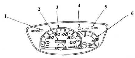
рис.
1
Кроме
того, на
панели может
находиться
индикатор
ближнего и
дальнего
света.
Панель
приборов
имеет
подсветку,
которая
включается в
зависимости
от модели при
заведенном
двигателе
переключателем
на три
положения: лвыключено╗,
лподсветка╗, лсвет╗,
или просто
при
включенном
двигателе (переключатель
отсутствует).
Спидометр
подключен
через тросик
к переднему
колесу.
Индикатор
наличия
масла (5)
загорается,
если
заканчивается
моторное
масло.
К ручкам
и кнопкам
управления (рис.
2) относятся:
1 и 2 — ручки
заднего и
переднего
тормозов;
3
— переключатель
ближнего-дальнего
света;
4 — переключатель
указателя
поворотов;
5 — кнопка
включения
сигнала;
6 — замок
зажигания;
7 — кнопка
включения
стартера.
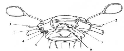
Рис.
2
Левая
ручка
приводит в
действие
тормоз
заднего
колеса, а
правая Ц
тормоз
переднего
колеса. Кроме
того, кнопка
стартера
срабатывает
только при
нажатии
левой или
правой ручки
тормоза при
положении
ключа
зажигания в
положении лON╗.
Переключатель
ближнего-дальнего
света
управляет
светом фары,
которая
включается в
зависимости
от модели или
просто после
запуска
двигателя,
если
отсутствует
трехпозиционный
переключатель
света (по
правилам
дорожного
движения
необходимо
включать
фары даже в
дневное
время), или
включением
трехпозиционного
переключателя
света в
крайнее
левое
положение
при
заведенном
двигателе.
При
включенном
дальнем
свете на
панели
приборов
включается
индикатор
дальнего
света.
Переключатель
указателя
поворотов
имеет три
положения:
левый
поворот,
правый
поворот и
нейтральное
положение.
Чтобы
перейти из
включенного
состояния в
нейтральное,
достаточно
просто
нажать на
кнопку.
Ручка
акселератора
через тросик
управляет одновременно
воздушной
заслонкой
карбюратора
и рычагом
подачи масла
в масляном
насосе,
согласуя
подачу масла
в
соответствии
с расходом
топлива в
нужной
пропорции.
Замок
зажигания.
Замок
зажигания
имеет 3
положения:
лOFF╗ —
лвыключено╗,
лON╗ — лвключено╗
лLOCK╗
— лзакрыто╗.
В
положение лON╗
начинает
работать все
элекрооборудование
и кроме того,
ключ
блокируется
в замке
зажигания от
случайного
выпадения.
В
положении лOFF╗
электрооборудование
отключается,
глушится
двигатель.
В
положении лLOCK╗
защелкивается
механическое
противоугонное
устройство,
блокирующее
поворот руля.
В положении
лOFF╗ и лLOCK╗
ключ
вынимается
из замка
зажигания.
Запуск
двигателя и
начало
движения.
|
Запустить
Во |
|
При
запуске
двигателя
необходимо
учитывать,
что
вращательный
момент от
двигателя к
заднему
колесу
передается
через
вариатор и
автоматическое
сцепление,
которое
включается
при больших
оборотах. И,
если по какой-то
причине
начальные
обороты
двигателя
при его
запуске
будут велики,
возникает
опасность
самопроизвольного
движения
мокика. Вот
почему
необходимо
ставить
мокик на
подножку при
втором
способе
запуска. А в
первом
случае
предусмотрена
блокировка
кнопки
стартера
тормозной
ручкой.
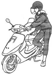
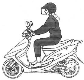
| Чтобы снять мокик с подножки, необходимо, поддерживая левую ручку тормоза, толкнуть мокик слегка вперед (рис. 4). |
|
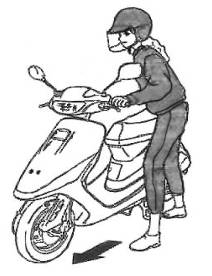
| Для начала движения надо надеть шлем, сесть на мокик (рис. 5) и начать движение, плавно повышая обороты двигателя ручкой акселератора. |
|
Техническая
эксплуатация.
При
эксплуатации
необходимо
учитывать
следующие
моменты:
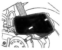
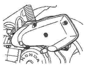
От
качества
воздушного
фильтра
зависит
долговечность
поршневой
группы,
поэтому,
открутив
винты (рис. 6),
сняв
поролоновый
фильтр (рис. 7),
при
необходимости
промыть в
бензине и
поставить на
место.
|
|
|
При
этом
особенно
тщательно
проверить,
нет ли
порывов в
самом
фильтре и как
плотно
прилегает
фильтр на
своем
посадочном
месте.Работа
поршневой
группы, а
также
подшипников
двигателя
зависит от
поступления
масла,
смешиваемого
с топливом в
карбюраторе.
Загорание
индикатора
наличие
масла на
панели
приборов
указывает на
то, что
необходимо
долить масло
в
специальный
бачок. Кроме
того,
необходимо
контролировать
состояние
рычага в
масляном
насосе (его
расположение
таково, что
велика
вероятность
загрязнения
дорожной
пылью,
смешанной с
парами масла,
что приводит
к залипанию
рычага в
режиме
максимальной
подачи масла,
а это
приводит к
переобогащению
маслом
топливной
смеси, к
плохому
сгоранию,
задымленности
и другим
негативным
последствиям.
Наличие
масла в
масляном
баке еще не
означает, что
с
поступлением
масла все в
порядке. Если
по какой-тот
причине
образовалась
воздушная
или грязевая
пробка в
шлангах
подачи масла,
то лубить╗
поршневую
группу можно
в считанные
минуты. Такая
опасность
возникает
особенно при
длительном
простое
мокика.
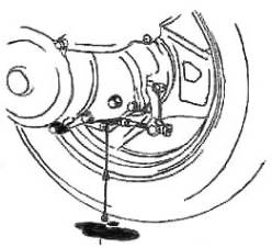
Для
контроля и
замены
трансмиссионного
масла в
редукторе
имеются
сливная (рис.
и заливная
пробки
(рис. 9). Масло
заливается
до уровня
заливной
пробки.
|
|
|
Необходимо
также
следить за
воздушным
шлангом,
соединяющим
картер
редуктора с
корпусом
воздушного
фильтра. Если
по какой-то
причине
шланг
выскочил из
корпуса
воздушного
фильтра, то
есть
опасность
попадания в
картер пыли
или воды.
Тормозная
система.
Задние
тормоза
барабанного
типа
включаются
левой
тормозной
ручкой,
регулируются
специальной
гайкой под
профиль (рис. 10).
|
|
|
По
положению
этой гайки
можно судить
о степени
износа
тормозной
колодки.
Кроме того,
для удобства
предусмотрена
блокировка
заднего
тормоза. Для
этого нужно
нажать левый
тормоз и
заблокировать
его рычагом (рис.
11)
| Передние тормоза могут быть барабанного или дискового типа (рис. 12) Во |
|
Краткие
технические
характеристики
мопедов
производства
Японии фирм Honda,
Suzuki.
Практически
все мопеды (99%)
имеют
двухтактный
двигатель,
принудительное
воздушное
охлаждение,
раздельную
систему
смазки, т.е.
есть бак под
бензин и бак
под масло —
чистый
бензин
подается в
карбюратор
где
смешивается
с маслом и
после этого
смесь
распыляется
в цилиндр.
Дозировка
масла
осуществляется
автоматически
специальным
масляным
насосом.
Бензин
рекомендуется
заливать с
октановым
числом не
ниже 93, масло
специальное
двухтактное
для
мототехники,
лучше
импортного
производства.
Расход масла
небольшой,
емкость
бачка (это
около одного
литра)
хватает
примерно на 150
литров
бензина.
Расход
топлива — 3
литра/100 км.
Все
современные
мопеды
оснащены
вариатором (механизм,
который под
нагрузкой
либо
расширяется
либо
сужается тем
самым
изменяя
передаточное
число). Привод
от двигателя
к вариатору
осуществляется
ременной
передачей.
Зажигание
— электронное.
Все
электрооборудование
— 12 V.
Тормоза-
задние
барабанные,
передние
могут быть
как дисковые
так и
барабанные.
На
всех мопедах
установлен
электростартер.
При
эксплуатации
следует
особое
внимание
уделять
качеству
воздушного
фильтра, т.к.
при его
износе
частицы
фильтра и
дорожная
пыль
попадает в
карбюратор,
вызывая тем
самым
засорение
жиклеров, а
пыль
работает как
абразив
между
поршнем и
цилиндром,
что приводит
к их
повышенному
износу.
Основные
поломки при
эксплуатации:
1.
Засорение
карбюратора.
2.Износ
цилиндро-поршневой
группы (при
правильной
эксплуатации
мопед б/у без
пробега по
России ходит
два года,
после чего
падает
мощность
двигателя и
требуется
замена ЦПГ).
Остальные
механизмы
практически
не требуют
ремонта.
ТЕХНИЧЕСКИЕ
ДАННЫЕ
НЕКОТОРЫХ
МОДЕЛЕЙ
Все
мопеды с
объемом
двигателя 49сс.
HONDA
1 .DJ-1 5.2 л.с/6500 об/мин,
М=52 кг,1990г
2.DIO
AF18 6.4
/6500, М-59 кг, 1990г
3.DIO
AF27 6.8
/6500, М-бЗ кг, с1992 по н.в.
4.DIO
ZX-1 AF28
7/6500,М=65 кг,с 1992 по н.в. (диск.торм.,
спойлер)
5.DIO
AF34 7
/6500, М= 69 кг, с1994 по н.в.
6.DIO
ZX-2 AF35
7.5/6500, М-69 кг, с 1994 по н.в.(диск.
торм., спойлер)
7.ТАКТ
AF16
5.8/6500,М=60 кг, 1990 г.
8.ТАКТ
AF24
6.4/6500.М-62 кг, 1992 г.
9.ТАКТАР306.1/6500,М=69
кг, с 1994 по 1998г.
10.PAL
NEW
4.5/6500, М- 51 кг, с 1992 по н.в.
11.LEAD
AF20 (50
СС) и LEAD HF05
(90 СС) 6/6500, М=б8 кг и 8.2/6500,
М = 78 кг
соответственно.
Оба с 1992 по н.в.
Оба с
дисковым
тормозом.
Двигатели
на DIO AF18
одинаковые с
ТАКТ AF24,
двигатели DIO AF27 и DIO
ZX-1
AF28
одинаковые,
есть лишь
небольшое
отличие в
зажигании,
также DIO
AF 34
и DIO ZX-2 AF35
отличаются
только
катушкой
зажигания.
SUZUKI
1.SEPIA
6.5/6500, М-63 кг, с1990 по н.в.
2.SEPIA
ZZ
7/6500, М-65 кг, с1990 по н.в. (диск.
торм., спойлер)
3.SEPIA
NEW
7/7000, М=б7 кг, с 1993 по н.в.
4.SEPIA
ZZ NEW 7.5/7000, М=б9 кг, с
1993 по н.в.( диск.
торм., спойлер)
5.ADDRESS 6.7/7000,M= 63 кг, 1991 г.
6.ADDRESS TUNE 7/7000, М-65 кг, 1991 г.
7.ADDRESS
V 6.7/7000, М=67 кг, с 1993 по н.в.
8.ADDRESS
V 100 (100 СС) 9/7000, М=75 кг, с 1993
по н.в.
9.HI—UP
6.5/6500, М=б2 кг, 1991 г.
10.LETS—I
6.8/7000, М= 68 кг, с 1996 по н.в.
11.LETS-11
6.8/7000, М=66 кг, с 1996 по н.в.
Практически
на всех
мопедах SUZUKI
двигатели
одинаковые
есть
различие
только по
зажиганию и
по
карбюраторам.
Только на LETS-1
и LETS-11
установлены
новые
двигатели,
между собой
они не
различаются.
Повышение
мощности на
мопедах
достигается
за счет
установки
тюнингового
зажигания и
за счет
увеличения
площади
впускных и
выпускных
окон.
На
всех моделях
под сиденьем
находится
багажник
большой
емкости
достаточный
для вмещения
гермошлема.
Возможные
причины
поломок и
способы их
устранения:
1.
Мопед не
заводится.
1.1.
Отсутствует
искра либо
она слабая (очень
редко)
1.1.1.
Заменить
свечу
1.1.2.
Перегорел
коммутатор (частое
явление на
таких как H.
Dio
AF34,
AF35
SR/ZX, S. LetТs
Ц I,
II,
H.
Job
ZR),
сгорела
катушка
зажигания (очень
редкое
явление)
1.1.3.
Перебит или
оборван
провод в цепи
(очень редко)
1.1.4.
Неисправен
замок
зажигания (очень
редко)
1.2.
Вспышка
искры не
совпадает с
верхнем
положением
поршня (ВМТ),
либо слишком
лраннее╗ или лпозднее╗
зажигание
1.3.
Бензин
не поступает
в цилиндр (очень
частое
явление)
1.3.1.
Засорены
жиклеры в
карбюраторе.
Необходимо
его снять,
промыть в
бензине и
продуть все
жиклеры
сжатым
воздухом.
Необходимо
обязательно
выкрутить
центральный
жиклер (он
находится в
поплавковой
камере) и
продуть его
отдельно.
После чистки
карбюратора
рекомендуется
заменить
фильтрующий
элемент в
воздушном
фильтре, т. к.
засорение
карбюратора
происходит
из-за него.
1.4.
Бензин
не поступает
в карбюратор
с бака.
1.4.1.
Неисправен
вакуумный
клапан Ц
ремонту не
подлежит.
1.4.2.
Ржавый бак и
ржавчиной
забило
фильтрующую
сетку в баке.
2.
Мопед
заводится, но
очень плохо и
обороты
двигателя
плавают.
Причиной
могут быть
все
вышеуказанные
причины, а
также:
2.1.
Износ
сальников по
коленвалу, за
счет чего
получается
дополнительный
подсос
воздуха. Они
меняются, не
половиня
двигатель (частое
явление на
мопедах
фирмы SUZUKI).
2.2.
Проверить
лепестковый
клапан между
карбюратором
и цилиндром.
Он должен
быть без
сколов и
не
пропускать
воздух в
обратную
сторону. Он не
должен быть
залипшим из-за
некачественного
бензина или
масла.
Залипший
клапан может
быть
причиной
того, что
мопед может
не
заводиться.
Ремонт или
замена
производится
, если есть
сколы,
притирка Ц
если он
пропускает
воздух в
обоих
направлениях,
мойка в
специальных
растворах Ц
если он
залипает.
Если имеется
большой скол
лепесткового
клапана,
рекомендуется
капитальный
ремонт
двигателя
для
извлечения
скола из
цилиндро-поршневой
группы (ЦПГ).
3.
Мопед
заводится, но
не тянет.
3.1.
Плохая
компрессия Ц
износ
поршневых
колец или их
пригорание к
поршню.
3.1.1.
При износе
цилиндра или
поршня нужно
заменить на
ремонтные
размеры. При
полном
отсутствии
компрессии
двигатель
может не
заводиться.
3.2.
Забит
глушитель (очень
частое
явление).
3.2.1.
Необходимо
снять
глушитель,
прожечь,
затем окунув
резко в
холодную
воду,
высыпать из
него
продукты
сгорания и
поставить на
место. Часто,
не зная этого,
меняют ЦПГ,
хотя надо
всего лишь
прожечь
глушитель.
3.3.
Изношен
вариаторный
ремень или
сам вариатор
или
разгонная
муфта. В
вариаторе и
разгонной
муфте
изнашиваются
пластиковые
ролики Ц их
следует
заменить.
4.
Мопед
заводится, но
слышен звон
или шуршание
из двигателя.
4.1.
Звон вызван
износом
игольчатых
подшипников
на пальце
поршня или на
шейке
коленвала.
4.2.
Звон вызван
дребезжанием
экранирующей
защиты на
колене
глушителя (подтянуть
болты).
Часто
путают п. 4.1. и п. 4.2.
4.3
Шуршание
двигателя
вызвано
износом
подшипников
из-за
попадания
воды в картер
Ц необходим
капитальный
ремонт
двигателя с
заменой
подшипников.
5.
Мопед не
заводится со
стартера. Сгорел
стартер.
5.1.
Неисправно
реле тормоза (как
известно,
напряжение
на стартер
подается
после
нажатия
переднего
или заднего
тормоза).
5.2.
Сел
аккумулятор.
6.
Не мигают
поворотники.
6.1.
Закисло
реле
поворотов (попробовать
постучать по
нему, если не
поможет Ц
заменить).
6.2.
Сел
аккумулятор (частое
явление на H.
Pal).
Все
остальные
неисправности
не
значительны.
Не
рекомендуется
эксплуатировать
такие модели,
как H. Dio AF34, AF35
ZX/SR
без
аккумуляторных
батарей, либо
с севшими
аккумуляторами.
В данном
случае
перегорает
коммутатор Ц
цена на рынке
около $50!!!
Назад
Используются технологии uCoz
|
Интернет-магазин Масла и смазки для автомобилей и мотоциклов, автохимия, расходные материалы, запчасти. |
Понедельник, 25.09.2023, 05:36 Приветствую Вас Гость
|
||||||||||||||
|
Руководство по эксплуатации скутеров HONDA DIO & Tact
СЕГОДНЯ В НАШЕМ МАГАЗИНЕ МОЖНО ЗАКАЗАТЬ ТОВАРЫ СО СКИДКОЙ…
|

the scooter
The scooter
Honda Dio
Manual device on operation preventive maintenance and repairBy
Andrey Levkovich Aka Dusha
Mail To: [email protected]
INDEX
1. Reduction and arbitrary symbols 2. General instructions on
repair 3. Identification 4. Description and the recommendation of
4.1 Recommendations regarding maintenance by 4.2 Recommendations
regarding control of scooter 5. Maintenance and the general audit
procedures and adjustment 5.1 Maintenance rate 5.2 Arrangement of
the elements of the systems of control, nourishment, electrical
equipment
5.3 Body elements (SK50M) 5.4 Adjustment of headlight 5.5
Adjustment of oil pump 5.6 Testing fuel pump 5.7 Cleaning air
filter 5.8 Pressure testing of the end of the compression stroke
5.9 Checking brake linings 6. Power unit 6.1 Oil pump 6.2 Oil tank
6.3 Choke 6.4 Carburetor 6.5 Petalous valve 6.6 Fuel tank 6.7 Fuel
pump 6.8 Air filter 6.9 Removal and installation of motor 6.10
Dismantling and assembling engine 6.11 Cylinder head, cylinder and
piston 6.12 Jackets of power unit 6.13 Kick- starter 6.14 Variator
6.15 Main drive 6.16 Carter engine 7. Checking and the repair of
power unit 8. Undercarriage 8.1 Front suspension and front brake
(SK50M) 8.2 Checking of the knot of front brake 8.3 Torr system
with disk front brake (SK50M) 8.4 Handle of gas 8.5 Rear suspension
and rear brake 8.6 Shock absorber 9. Electrical equipment 9.1
Storage battery 9.2 Regulator of voltage (rectifier) 9.3 Generator
9.4 Interrupter (block CDI) 9.5 Ignition coil 9.6 Checking the lead
angle of ignition 9.7 Starter 9.8 Sensor of fuel level 9.9 Sensor
of oil level 9.10 Lock of ignition 9.11 Switch of the turn
indicators of 9.12 Lamps 9.13 Steering switches of 9.14 Schematics
of the electrical equipment 1. Reduction and arbitrary
symbols of reduction
OFF……………………………… is switched off
ON…………………………………..vklyucheno
The arbitrary symbols 2. General instructions on repair
1. With the dismantling plot details in the appropriate order in
order to facilitate the subsequent
assembling. 2. Before the fulfillment of works with the
electrical equipment you will disconnect wire from
the negative terminal of storage battery. 3. Compulsorily
substitute split cotter pins, sealing gaskets, ferrules, stuffing
boxes and so forth
by the new. 4. If necessary it is necessary to bring the sealing
composition for averting the leakages to the
sealing gaskets. 5. Thoroughly soblyudayte all technical
specifications with respect to the values of the moment
of the delay of threaded connections. Compulsorily use a torque
wrench. 6. Depending on the nature of the repair produced can be
required the application of special materials and special tool for
the maintenance and the repair. 7. During the replacement of the
burnt out safety devices it is necessary to trace so that the new
safety fuse would be calculated for the appropriate current
strength. 3. Identification Series numbers are substituted in the
indicated in the figure places: The scooters of firm Honda are
differed from other stamps in terms of more durable (and heavier)
construction and sufficiently long-lived motors, which are worse
yielded to boosting. Are most common the scooters of family Dio
(Dio, Dio SR, Dio City Movement and others). Are in series produced
models Dio ZX and SuperDio ZX with the augmented engine, the disk
brakes and the sport suspension, and also different poluseriynye
Dio ZX — special modifications with the sport switchboards and the
carburetors, even by the more forced motors with the disposed
release, intensified by frame and suspensions. The weak place of
the usual Dio are the anthers of front fork. Bursting, they pass
mud inside the fork — as a result of bushing and feathers rapidly
they are worn out and go out of order. Furthermore, usual Dio have
a somewhat unsuccessful tuning of variator (with failure and
pickup), which hampers calm ride. These deficiencies are corrected
on the more expensive models Dio ZX. The scooters of family Tact
are intended for the beginning drivers. The merits of scooters
Honda include the vertical engine, which ensures larger than in
analogs, road clearance, and, in combination with the more rugged
construction, it makes it possible to use a machine not only around
the city, but also under the poor road conditions. With 1996-97 the
annual production of scooters Honda transferred into the Indian
branches of firm, which was reflected in the quality of those
completing and assembling of machines. 4. Description and
recommendation.4.1 Recommendations regarding the maintenance on the
scooters should be used gasoline with the octane number not lower
than 92. In the system of separate lubricant is compulsory the use
of special motor oil for the two-stroke engines. The tentative
consumption of oil — about 1 l on 1000 km with a decrease in the
oil level to the emergency reserve, lights up pilot lamp on the
combination of instruments. Sparkplugs should be checked every 1-2
thousand. km of path. After path in 4-8 thousand km (depending on
operating conditions) one should substitute sparkplug. The
periodicity of servicing air filter is 500 km with the ride along
the dusty roads. Transmission oil in the reducer of rear wheel
should be substituted yearly. 4.2 some recommendations regarding
control of scooter are examined below some distinctive special
features of the scooters of foreign production. 1. with the
zero-length launch and the acceleration from the low speed do not
twist out to the refusal the knob of gas to avoid the lift of
scooter to the rear wheel and the tilting. Especially this is
dangerous during the contact into the hill or with the significant
load on the baggage carrier. 2. because of the V-belt variator
acceleration occurs with a constant frequency of the rotation of
engine (close to the revolutions maximum power); therefore the
speed of scooter compulsorily should be checked on the speedometer.
3. with the braking should be used a front, and rear brake. With
the use only of rear brake is possible the heaping up of scooter
sideways, only front — the unguided drift or revolution through the
control. 4. small size of wheels and short base make scooter
sensitive to the unevennesses of road and they require the specific
strictness in control. 5. should be followed the height of the
protector of tires and as needed substituted they. Ride on the
scooter with the worn protector of wheels is extremely unsafe. 6.
with the passage of turnings one ought not to discard gas in the
turning in order to avoid of extension from the road. Turning
should be passed «vnatyag», checking gas or to in advance discard
it. Otherwise, with the sharp decrease of the frequency of rotation
centrifugal cohesion does not manage to disconnect engine from the
transmission and occurs intensive braking by engine. 7. always
include lower beam with the ride on the scooter. 5. Maintenance and
the general audit procedures and adjustment
Attention: in this management are used the following arbitrary
symbols of the modifications of scooters Honda: Honda
Dio…………….SK50M Honda Tact……………….SZ50P
ST………….Standart (base model) As…… of..AutoStand
(with the servodrive of support) DB…………… of..Disch Brake
(with the disk brake) the attention: removal and dismantling it is
main and aggregates it is achieved by way of the numbers, indicated
in the figures. Assembling and installation are accomplished in the
order, reverse to dismantling and to removal. Servicing
capacities:
Honda Dio The fuel tank……………………… of.4,0 l
motor oil…………………… of 0,8 l the transmission
oil……… of.0,09 l Honda Tact The fuel tank… of 5,0 l
(ST)/4,5 l (AS) motor oil…………………… of 1,2 l the
transmission oil……… of.0,09 l Fig. 3. recommended viscosity
of motor oilCarburetor
Carburetor…………… PB80 (Dio) or PB80W (Tact): the
diameter of the choke……………… of 14 mm Frequency of the
rotation of idling…………………… by 1700-1900 r/min Main
jet……… of.88 (Dio) or 78 (Tact) Idle jet…………
of.35
Pressure in the tires: the front wheel…………… of 1,25
kg/cm the rear wheel……………… of.2,00 kg/cm.Electrical
equipment:
Storage battery. …………… 12V/ 3Ah the lead angle of
ignition…………… 17 VMT of sparkplug: Dio:
NGK………………..BPR5HS, BPR6HS, BPR7HS, BPR8HR
Denso……………… W16FPR, W20FPR, W22FPR, W24FPRTact:
NGK………………..BR4HSA, BR8HSA Denso………………
W14FR-L, W24FR-LMaintenance rate:
1000 km — checking and cleaning the air filter — checking and
the adjustment of the rope of the gas — checking the brakes —
pressure testing in the tires — checking the light instruments —
checking sparkplugs through 3000 km — decarbonizing from the engine
— checking the level of the transmission oil — checking the
bearings of the steering column — checking and the adjustment of
the ropes of the brakes — checking the brake linings — checking the
storage battery — checking the wear of the tires — checking the
fastening — the lubricant of ropes 6000 km — the replacement of
sparkplugs — the replacement of the transmission oil — checking the
front fork — checking the shock absorbers — cleaning the
carburetor
Fig. 4. Arrangement Of the elements Of electrical equipment
(SK50M). 1 — rectifier, 2 — the sensor of oil level, 3 —
high-voltage wire,4 — main plait of installation, 5 — ignition
coil.
Fig. 5. arrangement of ropes and plaits of installation (SK50M).
1 — rope of front brake, 2 — rope of rear brake, 3 — resistor, 4 —
installation of the lock of ignition, 5 — rope of gas, 6 — light
switch, 7 — right plait of steering switches, 8 — left plait of
steering switches, 9 — switch of the light of headlights, 10 —
switch of turn indicators, 11 — switch of sound signal, 12 — wire
of stop signal (from the lever of rear brake), 13 — wire of left
turn indicator, 14 — wire of front headlight, 15 — wire of right
turn indicator, 16 — wire of stop signal (from the lever of front
brake).
Fig. 6. arrangement of ropes and plaits of installation
(SK50M).1 — the rope of speedometer, 2 — the basic plait of
installation, 3 — rope of rear brake, 4 — rope of gas, 5 — hose of
front brake.
Fig. 7. arrangement of the elements of the system of control
(SK50M). 1 — the rope of gas, 2 — the rope of rear brake, 3 — rope
of speedometer, 4 — rope of front brake, 5 — main plait of
installation.
Fig. 9. arrangement of the elements of the system of control and
nourishment (SK50M).1 — plait of the installation of generator and
starter,2 — the rope of gas,3 — the unit of safety devices,4 —
interrupter,5 — relay of starter,6 — wire of electric starter,7 —
left tube of the ventilation of crankcase,8 — tube of the oil
supply,9 — rope of rear brake,10 — control cable of oil pump,11 —
oil tube,12 — wire of the sensor of fuel level.
Fig. 10. arrangement of ropes and plaits of installation
(SK50M).1 — the rope of speedometer, 2 — the installation of the
lock of ignition, 3 — rope of gas, 4 — hose of front brake, 5 —
rope of speedometer, 6 — rope of rear brake, 7 — yokes of wires, 8
— resistor, 9 — switch of starter, 10 — light switch, 11,12 —
installation of steering switches, 13 — switch of the light of
headlight, 14 — switch of turn indicators, 15 — wire of stop
signal, 16 — wire of left turn indicator, 17 — wire of front
headlight, 18 — wire of right turn indicator.
Fig. 15. lateral revetment.1 — catch, 2 — lateral revetment, 3 —
screws of the fastening
Fig. 16. front fairing.1 — the screws of fastening, 2 — front
fairing, 3 — front cover, 4 — screws of fastening, 5 — catch.
Fig. 17. lateral fairing.1 — flanged nut, 2 — flanged bolt, 3 —
rear baggage carrier, 4 — catch, 5 — lateral fairing, 6 — screws of
fastening.
Fig. 18. outdoor revetment.1 — catchs, 2 — the revetment of
steps, 3 — clamp bolts.
Fig. 19. front cover.1 — clamp bolt, 2 — front cover, 3 —
catchs, 4 — screws of fastening.
Fig. 20. baggage hold.
1 — flanged bolts, 2 — padding, 3 — cover of oil tank, 4 — rear
baggage carrier, 5 — flanged bolt, 6 — flanged nut, 7 — baggage
hold.
Fig. 21. steering fairing.
1 — mirror of rear form, 2 — joints of the installation of front
headlight and turn indicators, 3 — the screws of fastening, 4 —
steering fairing, 5 — clamp bolt, 6 — catchs.
Fig. 22. rear wing.
1 — catch, 2 — the wire of rear turn indicator, 3 — rear wing, 4
— clamp bolts.
Fig. 23. LATERAL REVETMENT.
Fig. 24. steering fairing.
1 — the rope of speedometer, 2 — the tail end of the steering
fairing, 3 — bolt, 4 — installation of steering switches, 5 —
screws of fastening.
Fig. 25. Body Elements.1 — lateral revetment, 2 — baggage hold,
3 — lateral fairing, 4 — outdoor revetment, 5 — rear wing, 6 —
front fairing, 7 — front cover, 8 — steering fairing, 9 — the tail
end of the steering fairing
Fig. 26. baggage hold.
1 — clamp bolt, 2 — the cover of tank, 3 — the packing washer, 4
— the baggage hold
Fig. 27. outdoor revetment. 1 — catch, 2 — clamp bolt, 3 —
outdoor revetment, 4 — catch, wing, 3 — screws of fastening.
Fig. 28. front wing
1 — the screws of fastening, 2 — front
Fig. 29. front cover.
1 — the screws of fastening, 2 — clamp, 3 — clamp bolt, 4 —
front cover, 5 — catch.
Fig. 30. lateral fairing. 1 — catch, 2 — fairing, 3 — rear
baggage carrier, 4 — clamp bolt, 5 — rope, 6 — joints of wiring, 7
— screws of the fastening
Fig. 31. rear wing. 1 — clamp bolt of oil tank, 2 — relay, 3 —
bracket, 4 — clamp bolt, 5 — interrupter (knot CDI), 6 — clamp, 7 —
rear wing.
Fig. 32. adjustment of headlight Prover’te the direction of the
light beam of front headlight and, if necessary, adjust it with the
aid of the adjusting screw
Fig. 33. steering fairing. 1 — the screws of fastening, 2 — the
screw of fastening, 3 — padding of master brake cylinder, 4 —
steering fairing, 5 — mirror of rear form.
Fig. 34. the tail end of the steering fairing. 1 — joint of the
switch of stop signal, 2 — joint of the switch of stop signal, 3 —
joint of the installation of the combination of instruments, 4 —
rope of speedometer, 5 — screws of fastening, 6 — joint of the
switch of stop signal (ST, AS).
Fig. 35. adjustment of fuel pump. 1 — controlling lever, 2 — the
housing of oil pump, 3 — marker, 4 — adjusting nut. You will
completely unscrew the handle of gas (open the throttle) and
prover’te, that the markers on the housing of oil pump and the
controlling lever coincide. If necessary, adjust with the aid of
the adjusting nut.
Fig. 36. testing fuel pump. 1 — carburetor, 2 — fuel tube, 3 —
fastening. With the work of engine at the idling measure a quantity
of fuel, supplied with pump for 10 s. Nominal
volume……………… of 20 cc
5.7 cleaning of air filter
Wash the filtering element in washing oil, after which slightly
finish harvesting and give completely to get dry. You will look
around exterior view and state of porolon. If porolon has cracks
and scalings, it should be replaced by the new filtering element.
Wipe with the clean rags, moistened in the gasoline, the internal
part of the cover of filter and the internal cavity of housing. You
will look around the air duct of filter to the carburetor. The
casing of filter and air duct must not have cracks. Impregnate the
dry and clean filtering element before the installation in oil. For
this use special oil for the impregnation, or another oil with a
sufficient viscosity. You will distribute oil evenly along the
filter, but do not twist out the filtering element. Filter is ready
to installation if it abundantly it is impregnated with oil on the
entire surface and the thickness. 5.8 pressure testing of the end
of the compression stroke
1. Turn inside out sparkplug.
2. You will establish compressometer. 3. You will completely
unscrew the handle of gas. 4. Measure the value of compression with
cranking of crankshaft by the electric starter (frequency of
rotation not less than 600 r/min), the nominal pressure……… of
10 kg/sq cm the reason for insufficient compression they can be: a)
The damage of the padding of the cylinder head, b) The wear of
piston rings, the damage of piston, c) The wear of cylinder. 5.9
Checking of the brake linings
Prover’te the state of the brake linings. a) press on the brake
beams. b) prover’te the position of indicator. If indicator exceeds
the limits of the zone, shown in the form of marker, then should be
replaced the brake linings. 6. Power unit
Attention: removal and dismantling it is main and aggregates it
is achieved by way of the numbers, indicated in the figures.
Assembling and installation are accomplished in the order, reverse
to dismantling and to removal.
Fig. 37. oil pump. Removal and installation. 1 — oil tube, 2 —
the tube of oil feed, 3 — clamp bolts of the bracket of control
cable, 4 — control cable with the bracket, 5 — oil pump.
Fig. 38. oil tank. Removal and installation. (SK50M).1 — oil
tube, 2 — the joint of installation, 3 — nut of fastening, 4 —
clamp bolt, 5 — rear wing, 6 — clamp bolt, 7 — oil tank.
Fig. 40. choke. Dismantling and assembling. 1 — choke, 2 — the
rope of gas, 3 — spring of choke, 4 — padding, 5 — cover of
carburetor, 6 — shielding cap, 7 — catch, 8 — locking needle, 9 —
clamp.
Fig. 41. Carburetor. Removal and installation. 1 — choke, 2 —
fuel tube, 3 — tube of oil feed, 4 — wire of starting enricher, 5 —
clamp bolts of carburetor, 6 — O-ring seal, 7 — padding, 8 — O-ring
seal, 9 — carburetor.
Fig. 42. Carburetor. Dismantling and assembling. 1 — cover of
starting enricher, 2 — screws of fastening, 3 — about rate, 4 —
starting enricher, 5 — O-ring seal, 6 — screws of fastening, 7 —
float chamber, 8 — O-ring seal, 9 — axis of float, 10 — float, 11 —
needle valve, 12 — screw of quality, 13 — idle jet, 14 — main jet,
15 — emulsion tube.
Fig. 43. petalous valve. Dismantling and assembling. 1 — clamp
bolt, 2 — clamp bolt, 3 — protective housing, 4 — clamp bolts, 5 —
inlet pipe, 6 — padding, 7 — petalous valve, 8 — padding.
Fig. 44. fuel tank. Removal and installation. 1 — the joint of
installation, 2 — holder, 3 — sensor of fuel level, 4 — packing, 5
— fuel tube, 6 — clamp bolt, 7 — cover plate, 8 — fuel tank.
Fig. 45. fuel pump. Removal and installation (SK50M). 1 — fuel
filter, 2 — fuel tube, 3 — fuel tube, 4 — vacuum hose, 5 — clamp
bolt, 6 — fuel pump, 7 — nut of fastening, 8 — fuel pump
bracket
Fig. 47. air filter. Removal and installation (SK50M).1 — the
screws of fastening, 2 — the cover of air filter, 3 — filtering
element, 4 — screw of yoke, 5 — clamp bolts, 6 — casing of air of
filter, 7 — vent pipe.
Fig. 49. removal and installation of motor (SK50M).
1 — installation of generator and electric starter, 2 — wire of
starting enricher, 3 — oil tube, 4 — fuel tube, 5 — vacuum hose, 6
— cover of sparkplug, 7 — clamp bolt of rear shock absorber, 8 —
control cable of oil pump, 9 — rope of rear brake, 10 — nut of
fastening, 11 — clamp bolt, 12 — engine, 13 — bolt of the mounting
bracket of engine, 14 — mounting bracket of the engine
Fig. 51. cylinder head, cylinder and piston. Removal and
installation.1 — clamp bolts of cylinder head, 2 — cylinder head, 3
— padding of cylinder head, 4 — cylinder, 5 — padding of cylinder,
6 — check rings, 7 — wrist pin, 8 — piston, 9 — piston rings, 10 —
dilator of rings, 11 — needle bearing 12 — upper ring, 13 — lower
ring.
Fig. 52. Jackets of power unit. Removal and installation.
1- clamp bolts, rear jacket is 2nd, 3- padding, 4- clamp bolts,
front jacket is 5th, 6- padding, 7- the dowel pin.
Fig. 53. Kick- starter. Removal and installation.
1- drive gear, it is 2nd washer, 3- clamp bolt, 4- pedal of
kick- starter, it is 5th check ring, 6- washer, 7- the gear
quadrant of kick- starter, it is eighth return spring, 9
bushing.6.13 checking is the kicks of starter
1. Verify kick- starter.
A) Verify splined bushing.
b) Verify the gear quadrant of kick- starter.
c) Verify the gear the drive of kick- starter.
Fig. 54. 1- drive gear, it is 2nd retaining spring, 3- the dowel
pin.
Fig. 55
1. Verify the beds of the axes of gear quadrant and drive
gear.
Fig. 56. 1- splined bushing, it is 2- return spring, 3-
bushing.
Fig. 58. Variator. Removal and installation.
1- gear of electric starter, it is 2nd the nut of fastening, 3-
bushing, 4- fixed cheek of guide pulley, V-belt is 5th, 6- nut of
fastening the drum of cohesion, 7- drum of cohesion, the unit of
cohesion and follower pulley is eighth, 9 muff of variator, 10
clutch of the variator
Fig. 59. Clutch of variator. Dismantling and assembling.
1- clamp bolts, it is 2nd the cover of the clutch of variator,
3- the guiding plate, 4- guiding, it is 5th O-ring seal, 6- small
weights, 7- mobile cheek.
Fig. 60. Unit of cohesion. Dismantling and assembling.
1- nut of fastening, it is 2nd check ring, 3- washer, 4-
boot-tree of cohesion, it is 5th the spring of the boot-trees of
cohesion, 6- damper, 7- supporting disk, it is eighth the thrust
bushing of spring, 9 spring of follower pulley, 10 bushing, 11-
guide pin, 12- mobile cheek of follower pulley, 13- O-ring seal,
14- stuffing box, 15- bearing, 16- check ring, 17- bearing, 18- the
fixed cheek
Fig. 61. Main drive. Dismantling and assembling.
1- clamp bolt, it is 2nd the cover of reducer, 3- padding, 4-
the dowel pin, it is 5th washer, 6- output shaft, 7- washer, it is
eighth idlers, 9 washer, 10 input shaft.
Fig. 62. Removal of crankcase
Installation of crankcase
1. Turn away clamp bolts.
1. You will install right bearing.
2. Remove the cover of crankcase.
2. You will install left bearing.
3. You will establish crankshaft.
4. You will establish the left stuffing
box
Fig. 64. Crankcase. Removal and installation.
1- clamp bolts, it is 2nd the cover of crankcase 3- padding, 4-
the dowel pin, crankshaft is 5th, 6- right stuffing box, 7- left
stuffing box, right bearing is eighth, 9 left bearing.7. Checking
and the repair of power unit
1. You will clean cylinder head.
A) You will clean remainders of padding and carbon deposit from
injector face. Note: you be careful, in order not to injure the
injector face of cylinder, mated with the padding.
2. Verify cylinder head. By precision rule and by flat probe, as
shown in figure, verify the nonplanarity of the working injector
face of the cylinder
The maximum permissible non planarity of …………………
0,02 mm
if the value of non planarity exceeds maximum permissible, you
will replace cylinder head or grind it.
3. You will clean carbon deposit from internal surface of
exhaust of cylinder.
4. Verify cylinder.
A) By precision rule and by flat probe, as shown in figure,
verify the non planarity of the surface of cylinder.
The maximum permissible non planarity of ………………..
0,02 mm
if the value of non planarity exceeds maximum permissible, you
will replace cylinder or grind it.
6) measure the diameter of cylinder. Fig. 67
by Indicator- inside calipers measure the diameter of cylinder
at three levels in transverse (a) and longitudinal (b) directions,
as shown in figure. If the diameter more than maximum permissible,
you will replace it.
Diameter of the cylinder:
SK50M
nominal ………. 39,000-39,020 mm
maximum ……………….. 39,050 mm
SZ50P
marker A
nominal ………. 39,000-39,005 mm
maximum of ……………….. 39,050 mi
without the marker
nominal ………. 39,005-39,010 mm
maximum ……………….. 39,050 mm
the maximum conicity of …… 0,05 mm
5. You will clean piston. A) By scraper remove carbon
deposit
and others carbonic the deposit [s] piston head.
b) You will clean deposits from grooves of piston with the piece
of the broken ring.
c) By solvent and by soft hair brush you will finally clean
piston.
Note: do not use wire brush.
6. Verify piston.
A) by micrometer measure the diameter of piston skirt of at a
distance 4 mm rel.un. of edge, also, in the direction,
perpendicular to the axis of wrist pin, as shown in Fig. 70.
Diameter of the piston:
SK50M
nominal ……… 38,955-38,970 mm
minimum ………………… 38,900 mm
SZ50P without the marker
nominal ……… 38,960-38,965 mm
minimum ………………… 38,900 mm
marker A
nominal ……… 38,955-38,960 mm
minimum ………………… 38,900 mm
marker into
nominal ……… 38,965-38,970 mm
minimum ………………… 38,900 mm
7. You will determine clearance between the cylinder and the
piston, after finding a difference in the results of the
measurements of the diameter of piston and diameter of cylinder.
The nominal clearance of …… 0,035-0,050 mm
if clearance is more than nominal, you will replace piston and
cylinder.
8. Verify clearance in the piston-ring lock.
A) put piston ring into the cylinder up to the distance of 10 mm
from the parting plane.
b) by flat probe measure the clearance in the lock
Fig. 71
Nominal clearance of ………. 0,10-0,25 mm
The maximum clearance of ……………. 0,40 mm
if clearance in the lock is more than maximum, you will replace
piston ring. If clearance in the lock is more than maximum even
with the new piston ring, you will replace cylinder and piston.
9. Verify end clearance compression ring — piston groove, after
measuring by its flat probe, as shown in Fig. 73.
Nominal clearance of ………. 0,03-0,05 mm
Fig. 72
maximum clearance of ……………. 0,10 mm
if the clearance it is more permitted, you will replace
piston.
10. Verify wrist pin. (Fig. 74)
a) Put piston the finger you will be convinced with the bearing
into the connecting-rod end, that the finger it pivots without the
perceptible gap.
b) By inside calipers, measure the inside bore diameter under
the finger in the piston.
Nominal
Fig. 73
diameter of ……………….. 12,002-12,008 mm
the maximum diameter of …… 12,030 mm
c) using a micrometer, measure the diameter of wrist pin.
Nominal diameter of ………. 11,994-12,000 mm
the minimum diameter of ……. 11,980 mm if it is necessary,
you will replace piston and wrist pin in the collection.
11. Verify cohesion.
Fig. 74
a) Measure internal the diameter of the drum of cohesion.
The nominal diameter of …………………… 107,0-107,2
mm
the maximum diameter of …….. 107,5 mm
b) measure the thickness
of the friction lining.
Fig. 75
Fig. 76Nominal thickness of …….. 4,0-4,1 mm
the minimum thickness of …………. 2,0 mm
12. Verify the clutch of variator.
a) Verify the surfaces of mobile and stationary cheeks.
b) Measure the diameter of bushing. The
nominal
thickness of ……………… 20,035-20,085 mm
the minimum thickness of ……. 20,600 mm
c) Verify the diameter of roller.
Nominal diameter.15,92-16,08 mm
the minimum diameter of ……… 15,40 mm
13. Verify V-belt. (Fig. 77)
a) Verify the surface condition of belt (1).
b) Measure the width of belt (2).
Nominal width of …………… 15,5 mm
Fig. 77
Minimum width of …………… 14,5 mm
14. Verify follower pulley. (Fig. 78)
a) Verify surface condition mobile and fixed of pulleys.
b) Verify and you will if necessary replace stuffing box.
c) Verify the smoothness of the rotation of pulley.
g) verify the length of unloaded spring.
Nominal length of ……………… 98,1 mm
The minimum length of ……………… 92,8 mm
Fig. 78
15. Verify electric starter.
a) Verify the state of flywheel and idlers.
16. Checking main drive.
a) Verify the state the driven gear of main drive shaft, idlers,
slave gear.
b) Verify the state the radial bearings of driven gears.
17. Verify crankshaft.
a) Verify the bend of crankshaft. Maximum bend of …………..
0,04 mm8. The undercarriage
Attention: removal and the dismantling of units and aggregates
is achieved by way of numbers, indicated in the figure.
Assembling and installation is accomplished in the order,
reverse to dismantling and to removal.
Fig. 79. Removal and the installation of front wheel (SK50M)1-
Screw of fastening, the rope of speedometer is 2nd, 3- the nut of
front brake, 4- [vtupka] of brake beams, the rope of front brake is
5th, 6- nut of axis, 7- axle of front wheel, it is eighth bushing,
9 front wheel, 10 front wing, 11- unit of front brake, 12- anther,
13- left bearing, 14- the spacing collar, 15- right bearing.8.2
checking of the unit of front brake
1.Measure the free motion of brake beams and with
the need adjust it.
Nominal motion by ……………….. 10-20 mm
2. Measure the diameter of the internal surface
of brake drum.
Nominal diameter of ………… 95,0 mm
the maximum diameter of ………. 95,5 mm
3. Measure the thickness of the brake linings.
Nominal thickness of ………….. 3,0 mm
the minimum thickness of ………….. 2,0 mm
Fig. 80.
1- anther, left bearing is 2nd,
3- the spacing collar, 4- right bearing.
Fig. 81. Dismantling and the assembly of the unit of front brake
(SK50M).
1- brake shoes with the springs, clamp bolt is 2nd, 3- lever, 4-
indicator of the wear of cover plates, it is 5th return spring, 6-
unclasping fist, 7- stuffing box of unclasping fist, anther is
eighth, 9 gear of speedometer, 10 housing of the unit of the front
brake
Fig. 82. The steering column (SK50M).
Dismantling and assembling. 1- nut of fastening the steering
column, it is 2nd upper lid, 3- the steering column, 4- lower
cover, it is 5th bearings, 6- bearing cap, 7- clamp bolts, it is
eighth fastening front wing, 9 clamp bolt, 10 front fork.
Fig. 83. Front fork (SK50M).
Dismantling and assembling. 1- cover of the feather of front
fork, anther is 2nd, 3- check ring, 4- bushing, it is 5th the
spring of the motion of return, 6- fixed pipe of the feather of
front fork, 7- spring of the feather of front fork, rubber damper
is eighth, 9 mobile tip.8.3 Torr system with the disk front brake
(SK50M)
Fig. 84. Front wheel. Removal and installation.
1- screw of fastening the rope of speedometer, the rope of
speedometer is 2nd, 3- the nut of axis, 4- wheel axle, it is 5th
front wheel, 6- bushing, 7- drive of the speedometer
Handle of gas. Removal and installation.
1- nut of fastening, the link bolt of the lever of front brake
is 2nd, 3- the lever of front brake, 4- rope of front brake, clamp
bolt is 5th, 6- the upper lid of the handle of gas, 7- bracket of
the lever of front brake, the rope of gas is eighth, 9 handle of
gas.
Fig. 85. Retarding disc. Removal and installation.
1- anther, right bearing is 2nd, 3- the spacing collar, 4- left
bearing, it is 5th the clamp bolts of retarding disc, 6- retarding
disc.
Fig. 86. Brake support. Removal and installation.
1- clamp bolt, it is 2nd guide fingers, 3- the brake linings, 4-
plate.
Fig. 87. Master brake cylinder (SK50M). Dismantling and
assembling.
1- screws of fastening cylinder cover, it is 2nd cylinder cover,
3- the membrane, 4- bypass bolt and washer, brake hose is 5th, 6-
the link bolt of brake beams, 7- brake beams, it is eighth the
clamp bolts of holder, 9 holder of cylinder, 10 brake cylinder in
the collection, 11- screws of fastening the switch of stop signal,
12- switch of stop signal, 13- bushing, 14- check ring, 15- valve,
16- spring.
Checking front disk brake
1. Measure the free motion of brake beams and if necessary
adjust it.
Nominal motion by ………………. 10-20 mm
2. Measure the diameter of the piston of master brake
cylinder.
Nominal diameter of ………… 10,957-10,984 mm
the minimum diameter of ……. 10,910 mm
3. Measure the diameter of master brake cylinder.
Nominal diameter of ……………….. 11,000-11,043 mm
the maximum diameter of …….. 11,05 mm
4. Measure the diameter of the piston of front, brake.
Nominal diameter of ……………….. 30,148-30,198 mm
the minimum diameter of …….. 30,290 mm
5. Measure the diameter of the cylinder of front brake.
Nominal diameter of ……………….. 30,230-30,280 mm
the maximum diameter of …….. 11,05 mm
6. Measure the thickness of retarding disc.
Nominal thickness of ………….. 3,0 mm
the minimum thickness of ………….. 2,5 mm
Fig. 88. Support of front brake (SK50M). Dismantling and
assembling.
1- bypass bolt and washer, it is 2nd the cover of guide of
finger, 3- the clamp bolts of support, 4- Torr support, it is 5th
the guide fingers of boot-trees, 6- brake shoes, 7- adjusting
plate, it is eighth unclasping spring, 9 guide finger, 10 bracket
of support, 11- cover of guide of finger, 12- bushing, 13- piston,
14- case, 15- collar.8.4 Rear suspension and the rear brake
Fig. 89. Dismantling and assembling rear brake.
1-adjusting nut, it is 2nd the bushing of lever, 3- the rope of
rear brake, 4- brake shoes with the springs, the clamp bolt of
lever is 5th, 6- lever of rear brake, 7- return spring, the
indicator of the wear of the brake linings is eighth, 9 stuffing
box, 10 unclasping fist, 11- travel limiter of boot-tree.
Fig. 90. Removal and the installation of shock absorber.
1- lower clamp bolt, upper clamp bolt is 2nd, 3- rear shock
absorber.
Fig. 91. Dismantling and assembling shock absorber.
1- bushing, it is 2nd the grommet, 3- the lower opening of
fastening, 4- spring, it is 5th the lock nut, 6- rubber damper, 7 —
, shock absorber is eighth.1. Remove bushing.
2. Remove the grommet.
3. Remove the lower opening of fastening.
4. Remove spring.
5. Turn away the lock nut.
6. Remove rubber damper.
7. Remove the saddle of spring.
8. Remove shock absorber.
Assembling shock absorber is produced in the order, reverse to
its dismantling.
FIG. 93
9. Electrical equipment is
Note. For the designation of the colors of wires the following
reductions are used: B is white, Ch is black, Kr — red, [Kch] —
brown, Zh is yellow, With dark-blue, 3- green, [Rz] — pink, Sr —
gray, About the orange, TZ — dark green, [TKch] — dark brown.
In this case the first part of the designation indicates the
primary color of wire, the second (if there is) — the color of
strips.
Fig. 94. Arrangement of the elements of electrical
equipment.
1- interrupter, rectifier is 2nd, 3- of the relay of starter, 4-
storage battery, electric starter is 5th, 6- it soaked ignitions,
7- switch of sound signal, the switch of turn indicators is eighth,
9 switch of the light of headlight, 10 light switch, 11- switch of
starter, 12- resistor, 13- winding of ignition, 14- alternator, 15-
ignition coil, 16- ignition coil.9.1 The storage Battery
Fig. 95.
1- screws of fastening the cover of storage battery, it is 2nd
cover, 3- negative terminal, 4- positive terminal, it is 5th
storage battery.
FIG. 97 FIG. 96Checking storage battery
1.Verify stress on the outputs of storage battery, if it lower
than nominal, you will load storage battery. (Fig. 96)
nominal stress. 13,0-13,2 [v]
minimum stress ……… 12,3 [v]
2.Verify with the aid of the ammeter the absence of closing to
the mass of electrical equipment.
Maximum current of …………………… 1 mA (Fig. 97) 9.2
Regulator of voltage (rectifier)
verify resistance between the outputs of the rectifier
FIG. 98
9.3 Generator
Checking on the engine
Verify stress, issued by generator.
a) You will neglect engine.
b) You will include illumination, the switch of the light of
headlights — to the position HI.
c) Measure the stress.
Nominal stress
(with 5000 aboutmin) ……………. 12,6-13,6 [v]FIG. 99
Fig. 100. Dismantling and assembling generator.
1- clamp bolt, fan housing is 2nd, 3- clamp bolt, 4-
cooling-system fan, it is 5th flanged nut, 6- rotor (flywheel), 7-
key, the wire of generator is eighth, 9 joint of starter, 10 clamp
bolt, 11- clamp bolt of pulse generator, 12- pulse generator, 13-
clamp bolt of stator, 14- stator, 15- the protective bushing
Checking Generator
1. Verify winding impedance of generator.
Nominal resistance:
The winding of charging ………….. 0,2-1,0 Ohm is
the windings of illumination ……… 0,1-0,8 Ohm
2. Measure the resistance of resistor.
Nominal resistance:
6,7 0[m], 5[Vt] of …………………. 4,7-5,3[Om]
5,9 Ohm, 30 W ……………….. 5,6-6,2 Ohm Fig. 1019.4
interrupter (block CDI) Measure the resistance between the
conclusions of the joint of the interrupter:
Wire Resistance, Ohm are
Excitation winding black- redgreen 500-900
Pulse generator dark-blue- yellowgreen 50-200
Ignition coils black- yellowgreen 0,2-0,39.5 Ignition coil
Measure the resistance
of the primary winding of ignition coil.
Nominal resistance:
Dio ……………………………….. 0,2-0,3 Ohm
Tact ……………………………… 0,1-0,4 Ohm
Measure the resistance
the secondary winding of ignition coil.
Nominal resistance:
with the tip of the spark plug:
Dio ……………………………… 8,2-9,3 kilohms
Of tact of …………………………… 6,35-9,7
kilohms
without the tip of spark plug 2,7-3,4 kilohms
Fig. 102
Fig. 103
Fig. 104 9.6 Checking the angle ignition advance
Verify the lead angle of ignition
with the frequency of rotation 1800 aboutmin.
Nominal lead angle
of the ignition of …….. 173[doVMT]
Fig. 1059.7 The Starter
Fig. 106. Removal and the installation of starter.
1- clamp bolt, the bracket of control cable of oil pump is 2nd,
3- the clamp bolt of starter, 4- starter, it is 5th O-ring seal, 6-
joint of starter.
Fig. 107. Dismantling and assembling starter.
1- clamp bolt, stator is 2nd, 3- anchor, 4- brush holder, it is
5th spring, 6- O-ring seal, 7- front cover of starter.9.8 Sensor of
Fuel Level
Measure the resistance between the outputs
of the sensor of fuel level with different
position of float.FIG. 108Conclusions Position of the float
upper lower
green- yellowwhite 25-41 Ohm
450-750 Ohm
green- are dark-bluewhite 430-700 Ohm
25-41 Ohm
are yellowwhite- dark-bluewhite450-750 Ohm
450-750 Ohm9.9 sensor of oil levelYou will connect ohmmeter and
will ascertain that with the upper position of float there is no
conductivity, and with the lower position — there is conductivity
between the outputs of sensor.
Fig. 109
9.10 lock of ignition
Prover’te conductivity between the outputs of the lock of
ignition with its different positions, as shown in diagram FIG.
1109.11 Switch of turn indicators
Prover’te conductivity between the outputs of the switch of turn
indicators with its different positions, as shown in diagram.
FIG. 111
9.12 lamps
Fig. 112. front headlight
Fig. 113. Illumination of the combination of the instruments
FIG 114 1 — bolt, 2 — the lock of ignition, 3 — joint of the
lock of ignition.9.13 The steering switches
Prover’te conductivity between the outputs of light switch with
its different positions, as shown in diagram.
FIG 115Top of Form
Prover’te conductivity between the outputs (zheltyy/krasnyy and
green) of the switch of starter with its switch oned position.
HTMLCONTROL Forms.HTML:Hidden.1 Bottom of Form
FIG. 116Prover’te conductivity between the outputs of the switch
of sound signal with its switch oned position. Prover’te
conductivity between the outputs of the switch of the light of
headlights with its different positions, as shown in diagram.
FIG. 117
Fig. 118. backing lamp.1 — lamp of rear turn indicators, 2 —
lamp of stop signal, 3 — glass- stop signal, 4 — screws of
fastening, 5 — glass- turn indicator.
Fig. 119. arrangement of the elements of the system of the drive
of support.1 — the relay of generator, 2 — the relay of the system
of drive, 3 — joint of magnetic valve, 4 — magnetic valve, 5 — lock
of ignition, b — buzzer, 7 servo drive, 8 — knot of the support
Fig. 120. schematic of the system of drive.1 — storage battery,
2 — the safety device of yShcha, 3 — lock of ignition, 4 — relay of
generator, 5 — generator, 6 — magnetic valve, 7 — buzzer, 8 —
switch of drive, 9 — servodrive, 10 — relay of the system of
drive.
Ris.121. Schematic of electrical equipment (Dio SK50M).
1 — the switch of stop signals, 2 — the switch of starter, 3 —
light switch, 4 — lock of ignition, 5 — relay of starter, 6 —
storage battery, 7 — regulator of voltage (rectifier), 8 — sensor
of fuel level, 9 — sensor of oil level, 10 — right rear turn
indicator, 11 — stop signal and rear dimensional fire, 12 — left
rear turn indicator, 13 — sparkplug, 14 — interrupter (knot CDI),
15 — starting enricher, 16 — generator, 17 — electric starter, 18 —
resistor, 19 — sound signal, 20 — switch of the light of headlight,
21 — switch of turn indicators, 22 — sound signal, 23 — relay of
turn indicators, 24 — left front turn indicator, 25 — front
headlight, 26 — right front turn indicator, 27 — combination of
instruments, 28 — lamp of illumination, 29 — level indicator of
fuel, 30 — the pilot lamp of the oil level, 31 — the pilot lamp of
exceeding allowable speed, 32 — the safety device of «A, 33 —
ignition coil
_1239107449.unknown
_1239107451.unknown
Назад
Основные
детали и
правила
эксплуатации
мопедов.
Панель
приборов и
ручки
управления.
На
панели
приборов (рис.
1) находятся:
- Индикатор
превышения
скорости; - Счетчик
пробега; - Спидометр;
- Индикатор
указателя
поворотов; - Индикатор
наличия
масла; - Стрелочный
указатель
топлива.

рис.
1
Кроме
того, на
панели может
находиться
индикатор
ближнего и
дальнего
света.
Панель
приборов
имеет
подсветку,
которая
включается в
зависимости
от модели при
заведенном
двигателе
переключателем
на три
положения: лвыключено╗,
лподсветка╗, лсвет╗,
или просто
при
включенном
двигателе (переключатель
отсутствует).
Спидометр
подключен
через тросик
к переднему
колесу.
Индикатор
наличия
масла (5)
загорается,
если
заканчивается
моторное
масло.
К ручкам
и кнопкам
управления (рис.
2) относятся:
1 и 2 — ручки
заднего и
переднего
тормозов;
3
— переключатель
ближнего-дальнего
света;
4 — переключатель
указателя
поворотов;
5 — кнопка
включения
сигнала;
6 — замок
зажигания;
7 — кнопка
включения
стартера.

Рис.
2
Левая
ручка
приводит в
действие
тормоз
заднего
колеса, а
правая Ц
тормоз
переднего
колеса. Кроме
того, кнопка
стартера
срабатывает
только при
нажатии
левой или
правой ручки
тормоза при
положении
ключа
зажигания в
положении лON╗.
Переключатель
ближнего-дальнего
света
управляет
светом фары,
которая
включается в
зависимости
от модели или
просто после
запуска
двигателя,
если
отсутствует
трехпозиционный
переключатель
света (по
правилам
дорожного
движения
необходимо
включать
фары даже в
дневное
время), или
включением
трехпозиционного
переключателя
света в
крайнее
левое
положение
при
заведенном
двигателе.
При
включенном
дальнем
свете на
панели
приборов
включается
индикатор
дальнего
света.
Переключатель
указателя
поворотов
имеет три
положения:
левый
поворот,
правый
поворот и
нейтральное
положение.
Чтобы
перейти из
включенного
состояния в
нейтральное,
достаточно
просто
нажать на
кнопку.
Ручка
акселератора
через тросик
управляет одновременно
воздушной
заслонкой
карбюратора
и рычагом
подачи масла
в масляном
насосе,
согласуя
подачу масла
в
соответствии
с расходом
топлива в
нужной
пропорции.
Замок
зажигания.
Замок
зажигания
имеет 3
положения:
лOFF╗ —
лвыключено╗,
лON╗ — лвключено╗
лLOCK╗
— лзакрыто╗.
В
положение лON╗
начинает
работать все
элекрооборудование
и кроме того,
ключ
блокируется
в замке
зажигания от
случайного
выпадения.
В
положении лOFF╗
электрооборудование
отключается,
глушится
двигатель.
В
положении лLOCK╗
защелкивается
механическое
противоугонное
устройство,
блокирующее
поворот руля.
В положении
лOFF╗ и лLOCK╗
ключ
вынимается
из замка
зажигания.
Запуск
двигателя и
начало
движения.
|
Запустить
Во |
|

При
запуске
двигателя
необходимо
учитывать,
что
вращательный
момент от
двигателя к
заднему
колесу
передается
через
вариатор и
автоматическое
сцепление,
которое
включается
при больших
оборотах. И,
если по какой-то
причине
начальные
обороты
двигателя
при его
запуске
будут велики,
возникает
опасность
самопроизвольного
движения
мокика. Вот
почему
необходимо
ставить
мокик на
подножку при
втором
способе
запуска. А в
первом
случае
предусмотрена
блокировка
кнопки
стартера
тормозной
ручкой.
| Чтобы снять мокик с подножки, необходимо, поддерживая левую ручку тормоза, толкнуть мокик слегка вперед (рис. 4). |
|

| Для начала движения надо надеть шлем, сесть на мокик (рис. 5) и начать движение, плавно повышая обороты двигателя ручкой акселератора. |
|

Техническая
эксплуатация.
При
эксплуатации
необходимо
учитывать
следующие
моменты:
От
качества
воздушного
фильтра
зависит
долговечность
поршневой
группы,
поэтому,
открутив
винты (рис. 6),
сняв
поролоновый
фильтр (рис. 7),
при
необходимости
промыть в
бензине и
поставить на
место.
|
|
|


При
этом
особенно
тщательно
проверить,
нет ли
порывов в
самом
фильтре и как
плотно
прилегает
фильтр на
своем
посадочном
месте.Работа
поршневой
группы, а
также
подшипников
двигателя
зависит от
поступления
масла,
смешиваемого
с топливом в
карбюраторе.
Загорание
индикатора
наличие
масла на
панели
приборов
указывает на
то, что
необходимо
долить масло
в
специальный
бачок. Кроме
того,
необходимо
контролировать
состояние
рычага в
масляном
насосе (его
расположение
таково, что
велика
вероятность
загрязнения
дорожной
пылью,
смешанной с
парами масла,
что приводит
к залипанию
рычага в
режиме
максимальной
подачи масла,
а это
приводит к
переобогащению
маслом
топливной
смеси, к
плохому
сгоранию,
задымленности
и другим
негативным
последствиям.
Наличие
масла в
масляном
баке еще не
означает, что
с
поступлением
масла все в
порядке. Если
по какой-тот
причине
образовалась
воздушная
или грязевая
пробка в
шлангах
подачи масла,
то лубить╗
поршневую
группу можно
в считанные
минуты. Такая
опасность
возникает
особенно при
длительном
простое
мокика.
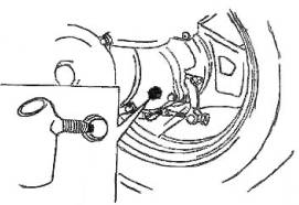
Для
контроля и
замены
трансмиссионного
масла в
редукторе
имеются
сливная (рис. 
и заливная
пробки
(рис. 9). Масло
заливается
до уровня
заливной
пробки.
|
|
|


Необходимо
также
следить за
воздушным
шлангом,
соединяющим
картер
редуктора с
корпусом
воздушного
фильтра. Если
по какой-то
причине
шланг
выскочил из
корпуса
воздушного
фильтра, то
есть
опасность
попадания в
картер пыли
или воды.
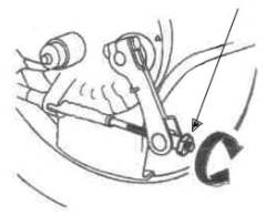
Тормозная
система.
Задние
тормоза
барабанного
типа
включаются
левой
тормозной
ручкой,
регулируются
специальной
гайкой под
профиль (рис. 10).
|
|
|


По
положению
этой гайки
можно судить
о степени
износа
тормозной
колодки.
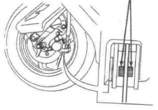
Кроме того,
для удобства
предусмотрена
блокировка
заднего
тормоза. Для
этого нужно
нажать левый
тормоз и
заблокировать
его рычагом (рис.
11)
| Передние тормоза могут быть барабанного или дискового типа (рис. 12) Во |
|

Краткие
технические
характеристики
мопедов
производства
Японии фирм Honda,
Suzuki.
Практически
все мопеды (99%)
имеют
двухтактный
двигатель,
принудительное
воздушное
охлаждение,
раздельную
систему
смазки, т.е.
есть бак под
бензин и бак
под масло —
чистый
бензин
подается в
карбюратор
где
смешивается
с маслом и
после этого
смесь
распыляется
в цилиндр.
Дозировка
масла
осуществляется
автоматически
специальным
масляным
насосом.
Бензин
рекомендуется
заливать с
октановым
числом не
ниже 93, масло
специальное
двухтактное
для
мототехники,
лучше
импортного
производства.
Расход масла
небольшой,
емкость
бачка (это
около одного
литра)
хватает
примерно на 150
литров
бензина.
Расход
топлива — 3
литра/100 км.
Все
современные
мопеды
оснащены
вариатором (механизм,
который под
нагрузкой
либо
расширяется
либо
сужается тем
самым
изменяя
передаточное
число). Привод
от двигателя
к вариатору
осуществляется
ременной
передачей.
Зажигание
— электронное.
Все
электрооборудование
— 12 V.
Тормоза-
задние
барабанные,
передние
могут быть
как дисковые
так и
барабанные.
На
всех мопедах
установлен
электростартер.
При
эксплуатации
следует
особое
внимание
уделять
качеству
воздушного
фильтра, т.к.
при его
износе
частицы
фильтра и
дорожная
пыль
попадает в
карбюратор,
вызывая тем
самым
засорение
жиклеров, а
пыль
работает как
абразив
между
поршнем и
цилиндром,
что приводит
к их
повышенному
износу.
Основные
поломки при
эксплуатации:
1.
Засорение
карбюратора.
2.Износ
цилиндро-поршневой
группы (при
правильной
эксплуатации
мопед б/у без
пробега по
России ходит
два года,
после чего
падает
мощность
двигателя и
требуется
замена ЦПГ).
Остальные
механизмы
практически
не требуют
ремонта.
ТЕХНИЧЕСКИЕ
ДАННЫЕ
НЕКОТОРЫХ
МОДЕЛЕЙ
Все
мопеды с
объемом
двигателя 49сс.
HONDA
1 .DJ-1 5.2 л.с/6500 об/мин,
М=52 кг,1990г
2.DIO
AF18 6.4
/6500, М-59 кг, 1990г
3.DIO
AF27 6.8
/6500, М-бЗ кг, с1992 по н.в.
4.DIO
ZX-1 AF28
7/6500,М=65 кг,с 1992 по н.в. (диск.торм.,
спойлер)
5.DIO
AF34 7
/6500, М= 69 кг, с1994 по н.в.
6.DIO
ZX-2 AF35
7.5/6500, М-69 кг, с 1994 по н.в.(диск.
торм., спойлер)
7.ТАКТ
AF16
5.8/6500,М=60 кг, 1990 г.
8.ТАКТ
AF24
6.4/6500.М-62 кг, 1992 г.
9.ТАКТАР306.1/6500,М=69
кг, с 1994 по 1998г.
10.PAL
NEW
4.5/6500, М- 51 кг, с 1992 по н.в.
11.LEAD
AF20 (50
СС) и LEAD HF05
(90 СС) 6/6500, М=б8 кг и 8.2/6500,
М = 78 кг
соответственно.
Оба с 1992 по н.в.
Оба с
дисковым
тормозом.
Двигатели
на DIO AF18
одинаковые с
ТАКТ AF24,
двигатели DIO AF27 и DIO
ZX-1
AF28
одинаковые,
есть лишь
небольшое
отличие в
зажигании,
также DIO
AF 34
и DIO ZX-2 AF35
отличаются
только
катушкой
зажигания.
SUZUKI
1.SEPIA
6.5/6500, М-63 кг, с1990 по н.в.
2.SEPIA
ZZ
7/6500, М-65 кг, с1990 по н.в. (диск.
торм., спойлер)
3.SEPIA
NEW
7/7000, М=б7 кг, с 1993 по н.в.
4.SEPIA
ZZ NEW 7.5/7000, М=б9 кг, с
1993 по н.в.( диск.
торм., спойлер)
5.ADDRESS 6.7/7000,M= 63 кг, 1991 г.
6.ADDRESS TUNE 7/7000, М-65 кг, 1991 г.
7.ADDRESS
V 6.7/7000, М=67 кг, с 1993 по н.в.
8.ADDRESS
V 100 (100 СС) 9/7000, М=75 кг, с 1993
по н.в.
9.HI—UP
6.5/6500, М=б2 кг, 1991 г.
10.LETS—I
6.8/7000, М= 68 кг, с 1996 по н.в.
11.LETS-11
6.8/7000, М=66 кг, с 1996 по н.в.
Практически
на всех
мопедах SUZUKI
двигатели
одинаковые
есть
различие
только по
зажиганию и
по
карбюраторам.
Только на LETS-1
и LETS-11
установлены
новые
двигатели,
между собой
они не
различаются.
Повышение
мощности на
мопедах
достигается
за счет
установки
тюнингового
зажигания и
за счет
увеличения
площади
впускных и
выпускных
окон.
На
всех моделях
под сиденьем
находится
багажник
большой
емкости
достаточный
для вмещения
гермошлема.
Возможные
причины
поломок и
способы их
устранения:
1.
Мопед не
заводится.
1.1.
Отсутствует
искра либо
она слабая (очень
редко)
1.1.1.
Заменить
свечу
1.1.2.
Перегорел
коммутатор (частое
явление на
таких как H.
Dio
AF34,
AF35
SR/ZX, S. LetТs
Ц I,
II,
H.
Job
ZR),
сгорела
катушка
зажигания (очень
редкое
явление)
1.1.3.
Перебит или
оборван
провод в цепи
(очень редко)
1.1.4.
Неисправен
замок
зажигания (очень
редко)
1.2.
Вспышка
искры не
совпадает с
верхнем
положением
поршня (ВМТ),
либо слишком
лраннее╗ или лпозднее╗
зажигание
1.3.
Бензин
не поступает
в цилиндр (очень
частое
явление)
1.3.1.
Засорены
жиклеры в
карбюраторе.
Необходимо
его снять,
промыть в
бензине и
продуть все
жиклеры
сжатым
воздухом.
Необходимо
обязательно
выкрутить
центральный
жиклер (он
находится в
поплавковой
камере) и
продуть его
отдельно.
После чистки
карбюратора
рекомендуется
заменить
фильтрующий
элемент в
воздушном
фильтре, т. к.
засорение
карбюратора
происходит
из-за него.
1.4.
Бензин
не поступает
в карбюратор
с бака.
1.4.1.
Неисправен
вакуумный
клапан Ц
ремонту не
подлежит.
1.4.2.
Ржавый бак и
ржавчиной
забило
фильтрующую
сетку в баке.
2.
Мопед
заводится, но
очень плохо и
обороты
двигателя
плавают.
Причиной
могут быть
все
вышеуказанные
причины, а
также:
2.1.
Износ
сальников по
коленвалу, за
счет чего
получается
дополнительный
подсос
воздуха. Они
меняются, не
половиня
двигатель (частое
явление на
мопедах
фирмы SUZUKI).
2.2.
Проверить
лепестковый
клапан между
карбюратором
и цилиндром.
Он должен
быть без
сколов и
не
пропускать
воздух в
обратную
сторону. Он не
должен быть
залипшим из-за
некачественного
бензина или
масла.
Залипший
клапан может
быть
причиной
того, что
мопед может
не
заводиться.
Ремонт или
замена
производится
, если есть
сколы,
притирка Ц
если он
пропускает
воздух в
обоих
направлениях,
мойка в
специальных
растворах Ц
если он
залипает.
Если имеется
большой скол
лепесткового
клапана,
рекомендуется
капитальный
ремонт
двигателя
для
извлечения
скола из
цилиндро-поршневой
группы (ЦПГ).
3.
Мопед
заводится, но
не тянет.
3.1.
Плохая
компрессия Ц
износ
поршневых
колец или их
пригорание к
поршню.
3.1.1.
При износе
цилиндра или
поршня нужно
заменить на
ремонтные
размеры. При
полном
отсутствии
компрессии
двигатель
может не
заводиться.
3.2.
Забит
глушитель (очень
частое
явление).
3.2.1.
Необходимо
снять
глушитель,
прожечь,
затем окунув
резко в
холодную
воду,
высыпать из
него
продукты
сгорания и
поставить на
место. Часто,
не зная этого,
меняют ЦПГ,
хотя надо
всего лишь
прожечь
глушитель.
3.3.
Изношен
вариаторный
ремень или
сам вариатор
или
разгонная
муфта. В
вариаторе и
разгонной
муфте
изнашиваются
пластиковые
ролики Ц их
следует
заменить.
4.
Мопед
заводится, но
слышен звон
или шуршание
из двигателя.
4.1.
Звон вызван
износом
игольчатых
подшипников
на пальце
поршня или на
шейке
коленвала.
4.2.
Звон вызван
дребезжанием
экранирующей
защиты на
колене
глушителя (подтянуть
болты).
Часто
путают п. 4.1. и п. 4.2.
4.3
Шуршание
двигателя
вызвано
износом
подшипников
из-за
попадания
воды в картер
Ц необходим
капитальный
ремонт
двигателя с
заменой
подшипников.
5.
Мопед не
заводится со
стартера. Сгорел
стартер.
5.1.
Неисправно
реле тормоза (как
известно,
напряжение
на стартер
подается
после
нажатия
переднего
или заднего
тормоза).
5.2.
Сел
аккумулятор.
6.
Не мигают
поворотники.
6.1.
Закисло
реле
поворотов (попробовать
постучать по
нему, если не
поможет Ц
заменить).
6.2.
Сел
аккумулятор (частое
явление на H.
Pal).
Все
остальные
неисправности
не
значительны.
Не
рекомендуется
эксплуатировать
такие модели,
как H. Dio AF34, AF35
ZX/SR
без
аккумуляторных
батарей, либо
с севшими
аккумуляторами.
В данном
случае
перегорает
коммутатор Ц
цена на рынке
около $50!!!
Назад
Используются технологии uCoz