-
Contents
-
Table of Contents
-
Bookmarks
Quick Links
ENGINE OVERHAUL
SEALANTS . . . . . . . . . . . . . . . . . . . .
SYSTEM . . . . . . . . . . . . . . . . . . . . . . .
TIMING BELT. . . . . . . . . . . . . . . . . . .
INSPECTION . . . . . . . . . . . . . . . . . . . . . . .
GROUP 11D
<4G63-Turbo>
CONTENTS
HOSE . . . . . . . . . . . . . . . . . . . . . . . . .
INSPECTION. . . . . . . . . . . . . . . . . . . . . . . .
INSPECTION. . . . . . . . . . . . . . . . . . . . . . . .
INSPECTION. . . . . . . . . . . . . . . . . . . . . . . .
INSPECTION. . . . . . . . . . . . . . . . . . . . . . . .
BLOCK . . . . . . . . . . . . . . . . . . . . . . . .
INSPECTION. . . . . . . . . . . . . . . . . . . . . . . .
11D-1
Summary of Contents for Mitsubishi 4g63
File Specifications:1009/1009578-4g63.pdf file (12 Feb 2023) |
Accompanying Data:
Mitsubishi 4g63 Engine PDF Service Manual (Updated: Sunday 12th of February 2023 12:31:46 AM)
Rating: 4.4 (rated by 76 users)
Compatible devices: Diesel Engine S12H-Y2PTAW-1, S 12 R, Engine cooling, S6S-Y3T61HF, S12U, 4M41, S6S, 4D68.
Recommended Documentation:
Service Manual (Text Version):
(Ocr-Read Summary of Contents of some pages of the Mitsubishi 4g63 Document (Main Content), UPD: 12 February 2023)
-
Mitsubishi 4g63 User Manual
-
Mitsubishi 4g63 User Guide
-
Mitsubishi 4g63 PDF Manual
-
Mitsubishi 4g63 Owner’s Manuals
Recommended: LM-U1060, AL-220S, HT, K6, Smartmount ST630P and assembly
Links & Tools
-
Operation and Maintenance Instructions Manual LC2A Lombardini Engines FOR FIRE PUMP APPLICATIONS Clarke UK, Ltd. Unit 1, Grange Works Lomond Road Coatbridge ML5 2NN United Kingdom TELE: +44(0)1236 429946 FAX: +44(0)1236 42274 www.clarkefire.com C132183 rev C 06/14 …
LC2A 18
-
3BDIRECT FUEL INJECTIONPage 3B-190-888438 JUNE 2002FUEL SYSTEMSection 3B – Direct Fuel InjectionTable of ContentsSpecifications 3B-2. . . . . . . . . . . . . . . . . . . . . . . . . . . Special Tools 3B-3. . . . . . . . . . . . . . . . . . . . . . . . . . . Notes: 3B-5. . . . . . . . . . . . . . . . . …
250 61
-
GENERAL INFORMATION 11A-0-3…………………………………….1. SPECIFICATIONS 11A-1-1………………………………………….SERVICE SPECIFICATIONS 11A-1-1………………………………REWORK DIMENSIONS 11A-1-3………………………………….TORQUE SPECIFICATIONS 11A-1-4………….. …
4G1 series 99
-
308–452Rev. CSupersedes Rev Band PCN CFirst choice whenquality counts.INSTRUCTIONS-PARTS LISTINSTRUCTIONSThis manual contains importantwarnings and information.READ AND KEEP FOR REFERENCE.HUSKY 307, PAIL MOUNTPRO 3500 Electrostatic PackageSee the Data Sheet, 305–666, for application information100 psi (0.69 …
Series A 16
Operating Impressions, Questions and Answers:
Руководство на английском языке по ремонту бензиновых двигателей Mitsubishi серии 4A9.
- Автор: —
- Издательство: Mitsubishi Motors Corp.
- Год издания: —
- Страниц: 51
- Формат: PDF
- Размер: 11,8 Mb
Руководство на английском языке по ремонту бензинового двигателя Mitsubishi серии 4G6 объемом 2,0 л.
- Автор: —
- Издательство: Mitsubishi Motors Corp.
- Год издания: —
- Страниц: 66
- Формат: PDF
- Размер: 2,4 Mb
Руководство на английском языке по ремонту бензиновых двигателей Mitsubishi моделей 4G61/4G63/4G64 1992-1993 годов выпуска.
- Автор: —
- Издательство: Mitsubishi Motors Corp.
- Год издания: —
- Страниц: 108+116
- Формат: PDF
- Размер: 6,5 Mb
Руководство на английском языке по ремонту бензинового двигателя Mitsubishi модели 6G72.
- Автор: —
- Издательство: Mitsubishi Motors Corp.
- Год издания: —
- Страниц: 123
- Формат: PDF
- Размер: 4,3 Mb
Руководство на английском языке по техническому обслуживанию и ремонту бензиновых двигателей Mitsubishi 1992-1993 годов выпуска.
- Автор: —
- Издательство: Mitsubishi Motors Corp.
- Год издания: 1992
- Страниц: 522
- Формат: PDF
- Размер: 14,6 Mb
Руководство на английском языке по техническому обслуживанию и ремонту бензиновых двигателей Mitsubishi серии 9G.
- Автор: —
- Издательство: Mitsubishi Motors Corp.
- Год издания: —
- Страниц: —
- Формат: PDF
- Размер: 244,3 Mb
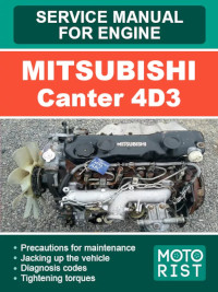
Руководство на английском языке по техническому обслуживанию и ремонту дизельных двигателей Mitsubishi серии 4D3 для грузовых автомобилей Mitsubishi Canter.
- Автор: —
- Издательство: Motorist
- Год издания: —
- Страниц: 240
- Формат: —
- Размер: —

Руководство на английском языке по техническому обслуживанию и ремонту дизельных двигателей Mitsubishi модели 4M40 для грузовых автомобилей Mitsubishi Canter.
- Автор: —
- Издательство: Motorist
- Год издания: —
- Страниц: 118
- Формат: —
- Размер: —

Руководство на английском языке по ремонту дизельного двигателя Mitsubishi модели 4D55.
- Автор: —
- Издательство: Mitsubishi Motors Corp.
- Год издания: 1986
- Страниц: —
- Формат: PDF
- Размер: 3,6 Mb

Сборник руководств на английском языке по техническому обслуживанию и ремонту двигателей Mitsubishi 1991-2005 годов выпуска.
- Автор: —
- Издательство: Mitsubishi Motors Corp.
- Год издания: —
- Страниц: —
- Формат: PDF
- Размер: 109,5 Mb
Руководство на английском языке по техническому обслуживанию и ремонту бензинового двигателя Mitsubishi модели 6A12 и КПП моделей F5M42/F5A42.
- Автор: —
- Издательство: Mitsubishi Motors Corp.
- Год издания: 1998
- Страниц: 189
- Формат: PDF
- Размер: 15,5 Mb
Сборник руководств на английском языке по техническому обслуживанию и ремонту КПП Mitsubishi 1990-2005 годов выпуска.
- Автор: —
- Издательство: Mitsubishi Motors Corp.
- Год издания: —
- Страниц: —
- Формат: PDF
- Размер: 69,6 Mb

Руководство по ремонту АКПП Mitsubishi моделей F3A2/F4A2/F4A3/F4AC1/W4A3.
- Автор: —
- Издательство: Mitsubishi Motors Corp.
- Год издания: 1994
- Страниц: 149
- Формат: PDF
- Размер: 7,5 Mb
Учебное пособие по конструкции и техническому обслуживанию дизельных двигателей Mitsubishi.
- Автор: —
- Издательство: Mitsibishi Motorss
- Год издания: —
- Страниц: 196
- Формат: PDF
- Размер: 8,0 Mb
Руководство по ремонту дизельных двигателей Mitsubishi серии 4M4.
- Автор: —
- Издательство: Mitsubishi Motors Corp.
- Год издания: —
- Страниц: 35+59
- Формат: PDF
- Размер: 1,7 Mb

Руководство по техническому обслуживанию и ремонту двигателей Mitsubishi 4D33/4D34-T4/4D35/4D36 и Hyundai D4AE/D4AF/D4AK.
- Автор: —
- Издательство: Легион-Автодата
- Год издания: —
- Страниц: 104
- Формат: —
- Размер: —

Руководство по техническому обслуживанию и ремонту дизельных двигателей Mitsubishi моделей 4M40/4M40T/4D56/4D56T.
- Автор: —
- Издательство: Легион-Автодата
- Год издания: —
- Страниц: 146
- Формат: —
- Размер: —

Руководство по техническому обслуживанию и ремонту бензиновых двигателей Mitsubishi V6 моделей 6A11/6A12/6G72/6G73/6G74.
- Автор: —
- Издательство: Легион-Автодата
- Год издания: —
- Страниц: 146
- Формат: —
- Размер: —

Руководство по техническому обслуживанию и ремонту двигателей Mitsubishi 6D22/6D22-T/6D24-T/6D40/6D40-T/8DC9/8DC10/8DC11 и Hyundai D6AB/D6AC/D6AU/D6AZ/D6CA/D8AX/D8AY.
- Автор: —
- Издательство: Легион-Автодата
- Год издания: —
- Страниц: 286
- Формат: —
- Размер: —

Руководство по техническому обслуживанию и ремонту двигателей Mitsubishi 4D56 и Hyundai D4BF.
- Автор: —
- Издательство: Легион-Автодата
- Год издания: —
- Страниц: 318
- Формат: —
- Размер: —

Руководство по техническому обслуживанию и ремонту двигателей Mitsubishi 4G63/4G63-T/4G64 и Hyundai G4JP/G4JS.
- Автор: —
- Издательство: Легион-Автодата
- Год издания: —
- Страниц: 238
- Формат: —
- Размер: —

Руководство по техническому обслуживанию и ремонту двигателей Mitsubishi 6D14/6D14-T/6D15-T/6D16/6D17 и Hyundai D6BR.
- Автор: —
- Издательство: Легион-Автодата
- Год издания: —
- Страниц: 242
- Формат: —
- Размер: —

![]()
11D-1
GROUP 11D
ENGINE OVERHAUL <4G63-Turbo>
CONTENTS
HOW TO USE THIS MANUAL. . . . . . 11D-2
GENERAL INFORMATION . . . . . . . . 11D-4 GENERAL SPECIFICATIONS . . . . . . 11D-4
SERVICE SPECIFICATIONS. . . . . . . 11D-5 REWOK DIMENSIONS . . . . . . . . . . . 11D-6
TORQUE SPECIFICATIONS . . . . . . . 11D-7
SEALANTS . . . . . . . . . . . . . . . . . . . . 11D-10
SPECIAL TOOLS. . . . . . . . . . . . . . . . 11D-11
ALTERNATOR AND IGNITION
SYSTEM . . . . . . . . . . . . . . . . . . . . . . . 11D-14
REMOVAL AND INSTALLATION . . . . . . . . 11D-14
SOLENOID AND VACUUM HOSE . . 11D-15
REMOVAL AND INSTALLATION . . . . . . . . 11D-15
TIMING BELT. . . . . . . . . . . . . . . . . . . 11D-16
REMOVAL AND INSTALLATION . . . . . . . . 11D-16 INSPECTION . . . . . . . . . . . . . . . . . . . . . . . 11D-26
FUEL AND EMISSION PARTS . . . . . 11D-28
REMOVAL AND INSTALLATION . . . . . . . . 11D-28
INLET MANIFOLD . . . . . . . . . . . . . . . 11D-30
REMOVAL AND INSTALLATION . . . . . . . . 11D-30
EXHAUST MANIFOLD . . . . . . . . . . . . 11D-31
REMOVAL AND INSTALLATION . . . . . . . . 11D-31
WATER PUMP AND WATER
HOSE . . . . . . . . . . . . . . . . . . . . . . . . . 11D-33
REMOVAL AND INSTALLATION . . . . . . . . 11D-33
ROCKER ARMS AND CAMSHAFT . . 11D-35
REMOVAL AND INSTALLATION . . . . . . . . 11D-35 INSPECTION. . . . . . . . . . . . . . . . . . . . . . . . 11D-37
CYLINDER HEAD AND VALVES. . . . 11D-40
REMOVAL AND INSTALLATION . . . . . . . . 11D-40 INSPECTION. . . . . . . . . . . . . . . . . . . . . . . . 11D-43
OIL PAN AND OIL PUMP. . . . . . . . . . 11D-46
REMOVAL AND INSTALLATION . . . . . . . . 11D-46 INSPECTION. . . . . . . . . . . . . . . . . . . . . . . . 11D-53
PISTON AND CONNECTING ROD . . 11D-55
REMOVAL AND INSTALLATION . . . . . . . . 11D-55 INSPECTION. . . . . . . . . . . . . . . . . . . . . . . . 11D-60
CRANKSHAFT AND CYLINDER
BLOCK . . . . . . . . . . . . . . . . . . . . . . . . 11D-62
REMOVAL AND INSTALLATION . . . . . . . . 11D-62 INSPECTION. . . . . . . . . . . . . . . . . . . . . . . . 11D-66
|
11D-2 |
ENGINE OVERHAUL <4G63-Turbo> |
|
HOW TO USE THIS MANUAL |
|
|
HOW TO USE THIS MANUAL |
M1113025100296
HOW TO USE THIS MANUAL
Scope of Service Explanations
This manual describes service procedures performed after removal of the engine from the vehicle.
For removal of the engine from the vehicle, installation of the engine in the vehicle, and on-vehicle inspection and service of the engine, please use the separate Workshop Manuals prepared for the vehicle.
How to Read Explanations
Service steps
(1)A component part drawing is shown at the beginning of each section to enable the technician to ascertain the installed condition of the component parts.
(2)Service steps are indicated by means of numbers in the component part drawing. Non-reusable parts are indicated as such,
and tightening torques are shown. ·Removal steps
The numbers of the part names match the numbers in the component part drawing and indicate the removal sequence. ·Installation steps
Installation steps are omitted wherever installation can be achieved simply by performing the removal steps in reverse. ·Disassembly steps
The numbers of the part names match the numbers in the component part drawing and indicate the disassembly sequence. ·Reassembly steps
Reassembly steps are omitted wherever reassembly can be achieved simply by performing the disassembly steps in reverse.
Classification of Service Points
Key service points, service standards, and instructions for using special tools are collated as service points and explained in detail.
<<A>>: Outward-pointing brackets denote removal service points or disassembly service points.
>>A<<: Inward-pointing brackets denote installation service points or reassembly service points.
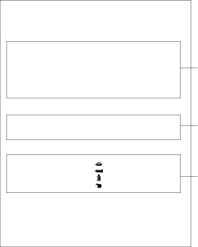
Lubricant and Sealant Symbols
Every location where a lubricant or sealant must be applied or added is indicated using a relevant symbol in the component part drawing and/or on the page after the component part drawing.
. . . . . . . . . . Grease
. . . . . . . . . . Sealant or form-in-place gasket (FIPG)
. . . . . . . . . . Brake fluid
. . . . . . . . . . Engine oil or gear oil
Inspection
Only those inspection procedures which use special tools or measuring appliances are described. You must perform general visual inspection and part cleaning whenever necessary although their procedures are not described in this manual.
AK202851
|
ENGINE OVERHAUL <4G63-Turbo> |
11D-3 |
|
HOW TO USE THIS MANUAL |
|
Page number |
Group title |
Section title |
||||
|
11-54 |
ENGINE OVERHAUL |
|||
|
CRANKSHAFT AND CYLINDER BLOCK |
||||
|
CRANKSHAFT AND CYLINDER BLOCK |
||||
|
REMOVAL AND INSTALLATION |
||||
|
3 |
2 |
|||
|
Apply engine oil |
Denotes non-reusable part. |
|||
|
to all moving |
11 ± 1 N·m |
1 |
||
|
parts before |
||||
|
installation. |
6 |
132 ± 5 N·m |
||
|
9 |
4 |
A |
||
|
16 |
8 |
|||
|
5 |
||||
|
9.0 ± 1.0 N·m |
||||
|
11 ± 1 N·m |
7 |
Tightening torque
15
14
13
12
11
25 ± 2 N·m + 90º to 100º
10
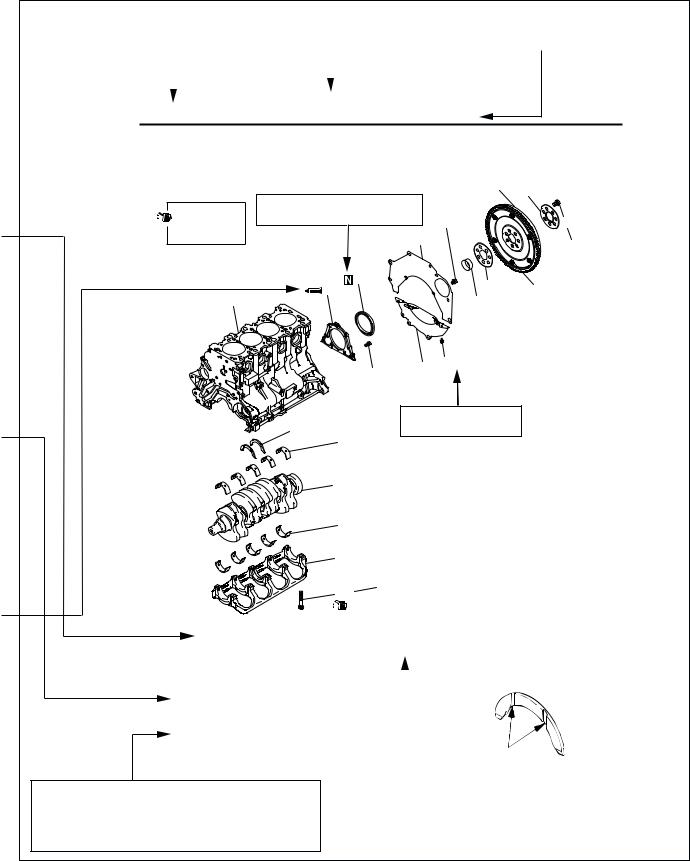
Removal steps 1. Drive plate bolt 2. Adapter plate 3. Drive plate
4. Crankshaft bushing
5. Rear plate
6. Bellhousing cover >>E<< 7. Oil seal case >>D<< 8. Oil seal
>>C<< 9. Bearing cap bolt 10. Bearing cap
>>B<< 11. Crankshaft bearing, lower >>A<< 12. Crankshaft
The alphabetical character in this category of heading matches that of the relevant removal steps, installation steps, disassembly steps, or reassembly steps.
AK204351AB
INSTALLATION SERVICE POINTS
>>A<< THRUST BEARING INSTALLATION
|
Grooves |
||||
|
AK100786AB |
||||
|
Procedures and cautions for removal, instal- |
||||
|
lation, disassembly, and reassembly are ex- |
||||
|
plained under this category of heading. |
AK300250 |
|||
|
11D-4 |
ENGINE OVERHAUL <4G63-Turbo> |
|
GENERAL INFORMATION |
GENERAL INFORMATION
|
VEHICLE AND ENGINE MODELS |
M1113000100523 |
||||
|
Vehicle name |
Vehicle |
Engine model |
Displacement |
Specification |
|
|
model |
mL |
||||
|
OUTLANDER |
CU2W |
4G63-7 |
1,997 |
Double overhead camshaft, 16-valve |
|
|
GENERAL SPECIFICATIONS |
|||
|
M1113000200779 |
|||
|
Item |
Specification |
||
|
Bore × stroke mm |
85 × 88 |
||
|
Displacement mL |
1,997 |
||
|
Combustion chamber |
Pentroof type |
||
|
Number of cylinders |
4 |
||
|
Valve mechanism |
Type |
Double overhead camshaft |
|
|
Number of intake valves |
2 |
||
|
Number of exhaust |
2 |
||
|
valves |
|||
|
Lash adjusters |
Hydraulic |
||
|
Rocker arms |
Roller cam followers |
||
|
Compresssion ratio |
9.0 |
||
|
Fuel injection system |
Electronically controlled multi-point injection (MPI) |
||
|
system |
|||
|
Ignition system |
Electronically controlled two-coil system |
||
|
Generator |
Alternator (with built-in IC regulator) |
||
|
Starter motor |
Gear reduction drive type |
||
|
ENGINE OVERHAUL <4G63-Turbo> |
11D-5 |
|
SERVICE SPECIFICATIONS |
SERVICE SPECIFICATIONS
M1113000300776
|
Item |
Standard value |
Limit |
||
|
TIMING BELT |
||||
|
Auto-tensioner rod extension length |
3.8 − 4.5 |
− |
||
|
(with timing belt installed) mm |
||||
|
Auto-tensioner rod extension length (when free) mm |
12.0 |
− |
||
|
Auto-tensioner rod retraction length |
Less than 1 |
− |
||
|
(when pressed with force of 98 to 196 N) mm |
||||
|
ROCKER ARMS AND CAMSHAFTS |
||||
|
Cam height mm |
34.91 |
34.41 |
||
|
CYLINDER HEAD AND VALVES |
||||
|
Cylinder head gasket surface warp mm |
Less than 0.05 |
0.2 |
||
|
Cylinder head gasket surface grinding limit |
− |
0.2 |
||
|
(including cylinder block grinding amount) mm |
||||
|
Cylinder head overall height mm |
131.9 − 132.1 |
− |
||
|
Cylinder head bolt nominal length mm |
− |
99.4 |
||
|
Valve margin mm |
Intake valves |
1.0 |
0.5 |
|
|
Exhaust valves |
1.5 |
1.0 |
||
|
Valve stem diameter mm |
6.6 |
− |
||
|
Valve face angle |
43.5° − 44° |
− |
||
|
Valve stem-to-guide clearance mm |
Intake valves |
0.02 − 0.05 |
0.10 |
|
|
Exhaust valves |
0.05 − 0.09 |
0.15 |
||
|
Valve height mm |
Intake valves |
109.5 |
109.0 |
|
|
Exhaust valves |
109.7 |
109.2 |
||
|
Valve stem projection mm |
Intake valves |
49.2 |
49.7 |
|
|
Exhaust valves |
48.4 |
48.9 |
||
|
Valve spring free height mm |
47.0 |
46.0 |
||
|
Valve spring load/height N/mm |
240/40 |
− |
||
|
Valve spring squareness |
1.5° or smaller |
4° |
||
|
Valve face-to-seat contact width mm |
0.9 − 1.3 |
− |
||
|
Valve guide inside diameter mm |
6.6 |
− |
||
|
Valve guide press-in height mm |
19.2 − 19.8 |
− |
||
|
OIL PAN AND OIL PUMP |
||||
|
Oil pump gear side clearance mm |
Drive gear |
0.08 − 0.14 |
− |
|
|
Driven gear |
0.06 − 0.12 |
− |
||
|
Oil cooler by-pass valve mm |
Dimension (Normal |
34.5 |
− |
|
|
temperature) |
||||
|
By-pass hole closing |
40.0 |
− |
||
|
temperature 97 to |
||||
|
103°C |
||||
|
11D-6 |
ENGINE OVERHAUL <4G63-Turbo> |
|||
|
REWOK DIMENSIONS |
||||
|
Item |
Standard value |
Limit |
||
|
Oil pressure at curb idle speed kPa |
78 or more |
− |
||
|
[oil temperature is 75 to 90°] |
||||
|
PISTONS AND CONNECTING RODS |
||||
|
Piston outside diameter mm |
85.0 |
− |
||
|
Piston ring side clearance in ring |
No. 1 |
0.03 − 0.07 |
0.1 |
|
|
groove mm |
||||
|
No. 2 |
0.02 − 0.06 |
0.1 |
||
|
Piston ring end gap mm |
No. 1 |
0.20 − 0.30 |
0.8 |
|
|
No. 2 |
0.30 − 0.45 |
0.8 |
||
|
Oil ring |
0.10 − 0.40 |
1.0 |
||
|
Piston pin outside diameter mm |
22.0 |
− |
||
|
Piston pin press-in load (at ambient temperature) N |
7,350 − 17,100 |
− |
||
|
Oil clearance at crankshaft pins mm |
0.03 − 0.05 |
0.1 |
||
|
Connecting rod big end thrust clearance mm |
0.10 − 0.25 |
0.4 |
||
|
CRANKSHAFT AND CYLINDER BLOCK |
||||
|
Crankshaft end play mm |
0.05 − 0.25 |
0.4 |
||
|
Crankshaft journal diameter mm |
57.0 |
− |
||
|
Crankshaft pin diameter mm |
45.0 |
− |
||
|
Oil clearance at crankshaft journals mm |
0.03 − 0.04 |
0.1 |
||
|
Cylinder block gasket surface warp mm |
0.05 |
0.1 |
||
|
Cylinder block gasket surface grinding limit |
− |
0.2 |
||
|
(including cylinder head grinding amount) mm |
||||
|
Cylinder block overall height mm |
284 |
− |
||
|
Cylinder bore diameter mm |
85 |
− |
||
|
Taper of cylinder mm |
0.01 or less |
− |
||
|
Cylinder-to-piston clearance mm |
0.02 − 0.04 |
− |
||
|
Crankshaft bearing cap bolt nominal length mm |
− |
71.1 |
||
REWOK DIMENSIONS
|
M1113024300394 |
||||
|
Item |
Standard value |
|||
|
CYLINDER HEAD AND VALVES |
||||
|
Diameter of oversize valve seat ring hole in cylinder head |
Intake |
0.3 oversize |
35.30 − 35.33 |
|
|
mm |
||||
|
0.6 oversize |
35.60 − 35.63 |
|||
|
Exhaust |
0.3 oversize |
33.30 − 33.33 |
||
|
0.6 oversize |
33.60 − 33.63 |
|||
|
Diameter of oversize valve guide hole in cylinder head mm |
0.05 oversize |
12.05 − 12.07 |
||
|
0.25 oversize |
12.25 − 12.27 |
|||
|
0.50 oversize |
12.50 − 12.52 |
|||
|
ENGINE OVERHAUL <4G63-Turbo> |
11D-7 |
||||
|
TORQUE SPECIFICATIONS |
|||||
|
TORQUE SPECIFICATIONS |
|||||
|
M1113023400989 |
|||||
|
Item |
N m |
||||
|
ALTERNATOR AND IGNITION COIL |
|||||
|
Oil level gauge guide bolt |
13 |
± 1 |
|||
|
Idler pulley bolt |
79 |
± 5 |
|||
|
Auto-tensioner assembly bolt (M8) |
24 |
± 4 |
|||
|
Auto-tensioner assembly bolt (M10) |
44 |
± 10 |
|||
|
Water pump pulley bolts |
8.8 ± 1.0 |
||||
|
Alternator brace bolt (flange bolt) |
23 |
± 3 |
|||
|
Alternator brace bolts (washer assembled bolt) |
22 |
± 4 |
|||
|
Alternator nuts |
44 |
± 10 |
|||
|
Crankshaft pulley bolts |
25 |
± 4 |
|||
|
Center cover bolts |
3.0 ± 0.5 |
||||
|
Ignition coil bolts |
10 |
± 2 |
|||
|
Spark plugs |
25 |
± 5 |
|||
|
SOLENOID AND VACUUM HOSE |
|||||
|
Vacuum pipe and hose assembly bolts |
11 ± 1 |
||||
|
EGR valve bolts |
20 |
± 2 |
|||
|
Engine hanger bolt |
19 |
± 3 |
|||
|
Solenoid valve assembly nut |
36 |
± 6 |
|||
|
Solenoid valve assembly bolts(M6) |
9.0 ± 1.0 |
||||
|
Solenoid valve assembly bolts(M8) |
23 |
± 4 |
|||
|
TIMING BELT |
|||||
|
Timing belt cover bolts (flange bolt) |
11 ± 1 |
||||
|
Timing belt cover bolt (washer-assembled bolt) |
9.0 ± 1.0 |
||||
|
Power steering pump bracket bolts |
49 |
± 9 |
|||
|
Tensioner pulley bolt |
48 |
± 5 |
|||
|
Tensioner arm bolt |
21 |
± 4 |
|||
|
Auto-tensioner bolts |
23 |
± 3 |
|||
|
Idler pulley bolt |
35 |
± 6 |
|||
|
Crankshaft angle sensor bolts |
8.8 ± 1.0 |
||||
|
Oil pump sprocket nut |
54 |
± 4 |
|||
|
Crankshaft bolt |
167 |
||||
|
Tensioner «B» bolt |
19 |
± 3 |
|||
|
Counterbalance shaft sprocket bolt |
45 |
± 3 |
|||
|
Rocker cover bolts |
3.5 ± 0.5 |
||||
|
Engine support bracket bolts |
49 |
± 5 |
|||
|
Camshaft sprocket bolts |
88 |
± 10 |
|||
|
11D-8 |
ENGINE OVERHAUL <4G63-Turbo> |
|||||
|
TORQUE SPECIFICATIONS |
||||||
|
Item |
N m |
|||||
|
FUEL SYSTEM |
||||||
|
Throttle body bolts |
19 |
± |
3 |
|||
|
Fuel pressure regulator bolts |
9.0 ± 2.0 |
|||||
|
Delivery pipe and injector assembly bolts |
11 ± 1 |
|||||
|
INLET MANIFOLD |
||||||
|
Inlet manifold stay bolts |
31 |
± |
3 |
|||
|
Inlet manifold bolts (M8) |
20 |
± |
2 |
|||
|
Inlet manifold bolts and nuts (M10) |
36 |
± |
6 |
|||
|
Detonation sensor |
23 |
± |
2 |
|||
|
EXHAUST MANIFOLD |
||||||
|
Engine hanger bolt |
19 |
± |
3 |
|||
|
Turbocharger heat protector bolts |
23 |
± |
3 |
|||
|
Oxygen sensor |
44 |
± |
5 |
|||
|
Exhaust fitting bracket bolts |
36 |
± |
5 |
|||
|
Exhaust fitting bolts |
59 |
± |
5 |
|||
|
Air outlet fitting bolts |
19 |
± |
1 |
|||
|
Oil return pipe bolts |
14 |
± |
1 |
|||
|
Exhaust manifold heat protector bolts |
23 |
± |
3 |
|||
|
Turbocharger assembly and pipe assembly bolts, nuts |
59 |
± |
5 |
|||
|
Oil pipe bolt (flange bolt) |
11 ± 1 |
|||||
|
Oil pipe bolt (eye bolt M10) |
17 |
± |
2 |
|||
|
Water pipe bolt (eye bolt M12) |
28 |
± |
5 |
|||
|
Water pipe bolt (flange bolt) |
10 |
± |
1 |
|||
|
Exhaust manifold nuts (M8) |
33 |
± |
6 |
|||
|
Exhaust manifold nuts (M10) |
55 |
± |
10 |
|||
|
WATER PUMP AND WATER HOSE |
||||||
|
Engine coolant temperature sensor |
29 |
± |
10 |
|||
|
Engine coolant temperature gauge unit |
10.8 |
± 1.0 |
||||
|
Water outlet fitting bolts |
13 |
± |
2 |
|||
|
Water inlet fitting bolts |
13 |
± |
2 |
|||
|
Thermostat housing bolts |
23 |
± |
4 |
|||
|
Water inlet pipe bolt (M8) |
13 |
± |
2 |
|||
|
Water pump bolts |
14 |
± |
1 |
|||
|
ROCKER ARMS AND CAMSHAFTS |
||||||
|
Camshaft position sensor bolt |
10 |
± |
1 |
|||
|
Cover bolts |
10 |
± |
2 |
|||
|
Camshaft position sensing cylinder bolt |
22 |
± |
4 |
|||
|
Camshaft position sensor support bolts |
14 |
± |
1 |
|||
|
Bearing cap bolts |
20 |
± |
1 |
|||
|
Oil delivery body bolts |
11 ± 1 |
|||||
|
ENGINE OVERHAUL <4G63-Turbo> |
11D-9 |
||||
|
TORQUE SPECIFICATIONS |
|||||
|
Item |
N m |
||||
|
CYLINDER HEAD AND VALVES |
|||||
|
Cylinder head bolts |
78 |
± 2 → 0 → 20 ± 2 → + 90° + 90° |
|||
|
OIL PUMP CASE AND OIL PAN |
|||||
|
Drain plug |
39 |
± 5 |
|||
|
Oil filter |
14 |
± 2 |
|||
|
Oil pan bolts |
9.0 ± 3.0 |
||||
|
Oil screen bolts |
19 |
± 3 |
|||
|
Oil pressure switch |
19 |
± 3 |
|||
|
Oil cooler by-pass valve |
54 |
± 5 |
|||
|
Relief plug |
44 |
± 5 |
|||
|
Oil filter bracket bolts |
19 |
± 3 |
|||
|
Plug cap |
23 |
± 3 |
|||
|
Flange bolt |
36 |
± 3 |
|||
|
Oil pump case bolts |
23 |
± 3 |
|||
|
Oil pump cover bolts |
17 |
± 1 |
|||
|
Oil pump cover screw |
10 |
± 2 |
|||
|
PISTONS AND CONNECTING RODS |
|||||
|
Connecting rod cap nuts |
20 |
± 2 → 90° to 94° |
|||
|
CRANKSHAFT AND CYLINDER BLOCK |
|||||
|
Flywheel bolts |
132 ± 5 |
||||
|
Rear plate bolt |
11 ± 1 |
||||
|
Bell housing cover bolts |
9.0 ± 1.0 |
||||
|
Rear oil seal case bolts |
11 ± 1 |
||||
|
Beam bearing cap bolts |
25 |
± 2 → 90° to 100° |
|||
|
11D-10 |
ENGINE OVERHAUL <4G63-Turbo> |
|
SEALANTS |
|
SEALANTS |
||
|
M1113000500703 |
||
|
Item |
Specified sealant |
|
|
Engine support bracket bolts |
Mitsubishi Genuine Part No.MD970389 |
|
|
or equivalent |
||
|
Semicircular packing |
3M ATD No.8660 or equivalent |
|
|
Rocker cover |
Mitsubishi Genuine Part No. MD970389 |
|
|
or equivalent |
||
|
Engine coolant temperature e gauge unit |
3M Nut Locking Part No.4171 or |
|
|
equivalent |
||
|
Engine coolant temperature sensor |
3M ATD No.8660 or equivalent |
|
|
Water outlet fitting* |
Mitsubishi Genuine Part No. MD970389 |
|
|
or equivalent |
||
|
Thermostat housing* |
||
|
Cylinder head (camshaft bearing cap fitting section) |
3M ATD No.8660 or equivalent |
|
|
Camshaft position sensor support* |
Mitsubishi Genuine Part No. MD970389 |
|
|
or equivalent |
||
|
Oil pressure switch |
3M ATD No.8660 or equivalent |
|
|
Oil pan* |
Mitsubishi Genuine Part No. MD970389 |
|
|
or equivalent |
||
|
Rear oil seal case* |
||
NOTE: *: Part to be sealed with a form-in-place gasket (FIPG)
FORM-IN-PLACE GASKET (FIPG)
This engine has several areas where the form-in-place gasket (FIPG) is used for sealing. To ensure that the FIPG fully serves its purpose, it is necessary to observe some precautions when applying it.
Bead size, continuity and location are of paramount importance. Too thin a bead could cause leaks. Too thick a bead, on the other hand, could be squeezed out of location, causing blocking or narrowing of fluid passages. To prevent leaks or blocking of passages, therefore, it is absolutely necessary to apply the FIPG evenly without a break, while observing the correct bead size.
FIPG hardens as it reacts with the moisture in the atmospheric air, and it is usually used for sealing metallic flange areas.
REMOVAL OF FIPG SEALED PARTS
Parts sealed with a FIPG can be easily removed without need for the use of a special method. In some cases, however, the FIPG in joints may have to be broken by tapping parts with a mallet or similar tool. You can also tap a flat, thin gasket scraper into the joint to break the FIPG, taking extreme care not to damage the mating surfaces.The oil pan cutter (MD998727) is available as a special tool for removing the oil pan. The tool, however, must not be.
CLEANING FIPG APPLICATION SURFACE
Thoroughly remove all substances deposited on the FIPG application surface, using a gasket scraper or wire brush. Make sure that the FIPG application surface is flat and smooth. Also make sure that the surface is free from oils, greases and foreign substances. Do not fail to remove old FIPG that may remain in the fastener fitting holes.
APPLICATION OF FIPG
Applied FIPG bead should be of the specified size and free of any break. FIPG can be wiped away unless it has completely hardened. Install the mating parts in position while the FIPG is still wet (in less than 15 minutes after application). Do not allow FIPG to spread beyond the sealing areas during installation. Avoid operating the engine or letting oils or water come in contact with the sealed area before a time sufficient for FIPG to harden (approximately one hour) has passed. FIPG application method may vary from location to location. Follow the instruction for each particular case described later in this manual.
![]()
|
ENGINE OVERHAUL <4G63-Turbo> |
11D-11 |
|
SPECIAL TOOLS |
SPECIAL TOOLS
M1113000600788
|
Tool |
Number |
Name |
Use |
|
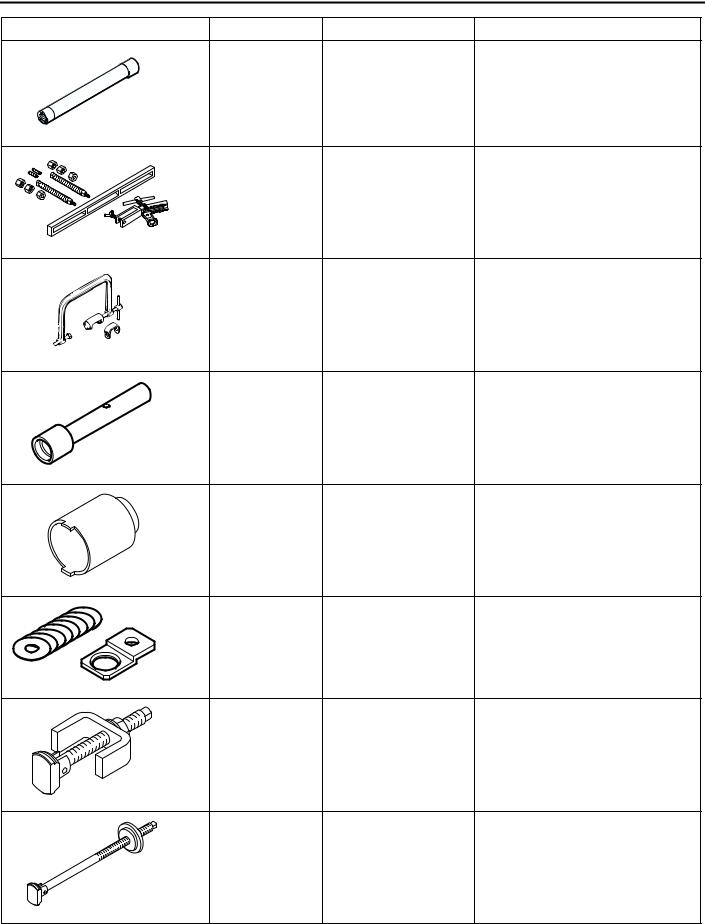
MD998781 |
Flywheel stopper |
Retention of flywheel |
D998781
|
MD998778 |
Crankshaft sprocket |
Removal of crankshaft sprocket |
|
puller |
and crankshaft sprocket B |
|
MD998785 |
Sprocket stopper |
Retention of counterbalancer |
|
shaft sprocket |
|
MD998767 |
Tension pulley socket |
Manipulation of tensioner pulley |
|
wrench |
during adjustment of timing belt |
|
|
tension |
||
|
D998767 |
||
|
MD998738 |
Set screw |
Retention of tensioner arm and |
|
auto-tensioner during timing belt |
||
|
installation |
||
|
D998738 |
|
MD998713 |
Camshaft oil seal |
Installation of camshaft oil seal |
|
installer |
D998713
|
MD998442 |
Air bleed wire |
Air bleeding of lash adjuster |
|
11D-12 |
ENGINE OVERHAUL <4G63-Turbo> |
||
|
SPECIAL TOOLS |
|||
|
Tool |
Number |
Name |
Use |
|
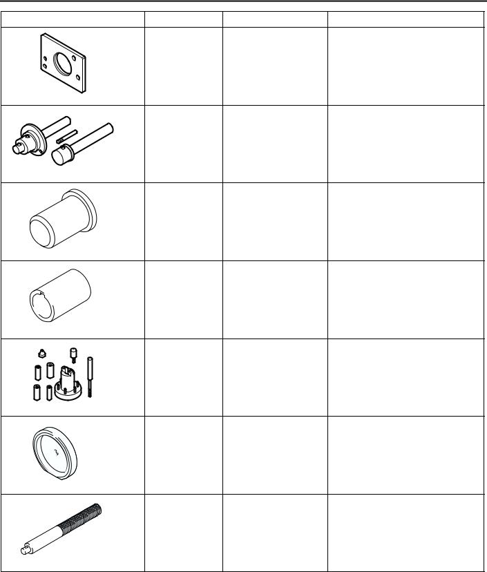
MB991654 |
Cylinder head bolt |
Removal and installation of |
|
|
wrench |
cylinder head bolts |
||
|
B991654 |
|||
|
MD998772 |
Valve spring |
Compression of valve spring |
|
|
compressor |
|
MD998735 |
Valve spring |
Compression of valve spring |
|
compressor |
|
MD998737 |
Valve stem seal |
Installation of valve stem seal |
|
installer |
|
MD998162 |
Plug wrench |
Removal and installation of front |
|
case plug cap |
||
|
(Use with MD998783.) |
|
MD998783 |
Plug wrench retainer Removal and installation of front |
|
case plug cap |
|
|
(Use with MD998162.) |
|
MD998371 |
Silent shaft bearing |
Removal of counterbalancer shaft |
|
puller |
front bearing |
|
MD998372 |
Silent shaft bearing |
Removal of counterbalancer shaft |
|
puller |
front and rear bearings |
|
ENGINE OVERHAUL <4G63-Turbo> |
11D-13 |
||
|
SPECIAL TOOLS |
|||
|
Tool |
Number |
Name |
Use |
|
MB991603 |
Silent shaft bearing |
Guide and stopper for removal |
|
|
installer stopper |
and press-fitting of |
||
|
counterbalancer shaft rear |
|||
|
bearing |
|||
|
MD998705 |
Silent shaft bearing |
Press-fitting of counterbalancer |
|
|
installer |
shaft front and rear bearings |
|
MD998375 |
Crankshaft front oil |
Installation of crankshaft front oil |
|
seal installer |
seal |
|
MD998285 |
Crankshaft front oil |
Guide for installation of |
|
seal guide |
crankshaft front oil seal |
D998285
|
MD998780 |
Piston pin setting tool Removal and press-fitting of |
|
piston pin |
|
MD998776 |
Crankshaft rear oil |
Installation of crankshaft rear oil |
|
seal installer |
seal |
D998776
|
MB990938 |
Handle |
Installation of crankshaft rear oil |
|
seal |
||
|
(Use with MD998776.) |

|
11D-14 |
ENGINE OVERHAUL <4G63-Turbo> |
|
ALTERNATOR AND IGNITION SYSTEM |
ALTERNATOR AND IGNITION SYSTEM
REMOVAL AND INSTALLATION
M1113001000701
|
12 |
3.0 ± 0.5 N·m |
||||
|
2 |
1 |
||||
|
10 ± 2 N·m |
|||||
|
13 |
|||||
|
14 |
|||||
|
13 ± 1 N·m |
15 |
||||
|
25 ± 5 N·m |
|||||
|
3 |
10 |
||||
|
44 ± 10 N·m |
|||||
|
4 |
|||||
|
9 |
|||||
|
22 ± 4 N·m |
|||||
|
8 |
|||||
|
7 |
|||||
|
44 ± 10 N·m |
23 ± 3 N·m |
||||
|
8.8 ± 1.0 N·m |
|||||
|
25 ± 4 N·m |
|||||
|
79 ± 5 N·m |
11 |
||||
|
6 |
|||||
|
24 ± 4 N·m |
5 |
||||
|
AK305988AC |
|||||
|
Removal steps |
Removal steps (Continued) |
||||
|
1. |
Oil level gauge |
9. Alternator brace |
|||
|
2. |
O-ring |
10. Alternator |
|||
|
3. |
Oil level gauge guide |
11. Crankshaft pulley |
|||
|
4. |
O-ring |
12. Center cover |
|||
|
5. |
Idler pulley |
13. Spark plug cable |
|||
|
6. |
Cap |
14. Ignition coil |
|||
|
7. |
Auto-tensioner assembly |
15. Spark plug |
|||
|
8. |
Water pump pulley |

|
ENGINE OVERHAUL <4G63-Turbo> |
11D-15 |
|
SOLENOID AND VACUUM HOSE |
SOLENOID AND VACUUM HOSE
REMOVAL AND INSTALLATION
M1113025300074
20 ± 2 N·m
4
|
5 |
19 ± 3 N·m |
|
|
8 |
23 ± 4 N·m |
9.0 ± 1.0 N·m
36 ± 6 N·m
11 ± 1 N·m
7
11 ± 1 N·m
2
1
|
AK400296AB |
|||
|
Removal steps |
Removal steps (Continued) |
||
|
1. |
Vacuum pipe and hose assembly |
5. |
EGR valve gasket |
|
2. |
Vacuum pipe and hose assembly |
6. |
Solenoid valve |
|
3. |
Vacuum pipe and hose assembly |
7. |
Solenoid valve |
|
4. |
EGR valve |
8. |
Engine hanger |

|
11D-16 |
ENGINE OVERHAUL <4G63-Turbo> |
|
TIMING BELT |
TIMING BELT
REMOVAL AND INSTALLATION
|
M1113001900867 |
||||
|
24 |
3.5 ± 0.5 N·m |
|||
|
21 |
28 |
|||
|
1 |
||||
|
11 ± 1 N·m |
22 |
25 |
||
|
20 |
5 6
48 ± 5 N·m
 23
23
|
21 ± 4 N·m |
26 |
||||||||
|
11 ± 1 N·m |
12 |
7 |
|||||||
|
23 ± 3 N·m |
27 |
||||||||
|
32 |
11 ± 1 N·m |
||||||||
|
11 |
11 ± 1 N·m |
33 |
|||||||
|
167 N·m |
29 |
||||||||
|
2 |
49 ± 5 N·m |
||||||||
|
9.0 ± 1.0 N·m |
|||||||||
|
31 |
4 |
45 ± 3 N·m |
16 17 |
||||||
|
19 ± 3 N·m |
3 |
||||||||
|
14 |
|||||||||
|
30 |
34 |
9 |
|||||||
|
88 ± 10 N·m |
19 |
||||||||
|
49 ± 9 N·m |
|||||||||
|
15 |
18 8.8 ± 1.0 N·m |
||||||||
|
13 |
|||||||||
|
8 |
10 |
AK305989AB |
|||||||
|
35 ± 6 N·m |
54 ± 5 N·m |
||||||||
|
Removal steps |
<<D>> |
>>I<< |
Removal steps (Continued) |
||||||
|
1. Timing belt front upper cover |
12. Crankshaft sprocket |
||||||||
|
2. Timing belt front lower cover |
>>I<< |
13. Crankshaft sensing blade |
|||||||
|
<<A>> |
>>M<< |
3. Power steering pump bracket |
<<E>> |
>>H<< |
14. Tensioner «B» |
||||
|
4. |
Timing belt |
15. Timing belt «B» |
|||||||
|
>>L<< |
5. |
Tensioner pulley |
<<F>> |
>>G<< |
16. Counterbalancer shaft sprocket |
||||
|
6. |
Tensioner arm |
>>F<< |
17. Spacer |
||||||
|
>>K<< |
7. Auto-tensioner |
<<G>> |
>>E<< |
18. Crankshaft sprocket «B» |
|||||
|
8. |
Idler pulley |
19. Crankshaft key |
|||||||
|
<<B>> |
>>J<< |
9. |
Crankshaft angle sensor |
20. Breather hose |
|||||
|
10. Oil pump sprocket |
21. PCV hose |
||||||||
|
<<C>> |
>>I<< |
11. Crankshaft bolt |
22. PCV valve |

|
ENGINE OVERHAUL <4G63-Turbo> |
11D-17 |
|
TIMING BELT |
Removal steps (Continued)
23.PCV valve gasket
24.Oil filler cap >>D<< 25. Rocker cover
>>D<< 26. Rocker cover gasket «A»
|
>>C<< |
27. Rocker cover gasket «B» |
|
28. Semicircular packing |
|
|
>>B<< 29. Engine support bracket |
|
|
<<H>> >>A<< |
30. Camshaft sprocket bolt |
31.Camshaft sprocket
32.Timing belt rear cover, right
33.Timing belt rear upper cover, left
34Timing belt rear lower cover, left
REMOVAL SERVICE POINTS <<A>> TIMING BELT REMOVAL
1.If the timing belt is to be reused, make an arrow mark with something like chalk on the back of the belt indicating the direction of rotation so it may be reinstalled in the same direction.

 CAUTION
Never remove the timing belt with any piston at the top dead center (TDC). If a piston is at TDC, the exhaust valves of the cylinder are pushed by the exhaust cams, compressing the valve springs. If the belt is removed under this condition, the sprocket will be turned in the reverse direction by the force of the springs, incurring risk of injury.
2.Set the timing mark of the exhaust camshaft sprocket to a point about one tooth before the TDC of the No.1 cylinder piston on compression stroke.
3.Loosen the lock nut of the tensioner pulley, then remove the timing belt.
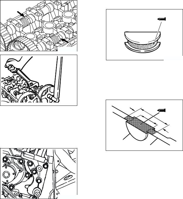
<<B>> OIL PUMP SPROCKET REMOVAL
1. Remove the plug on the left side of cylinder block.
|
Crosspoint |
|
screwdriver |
|
AK202825AD |
2.Insert a crosspoint screwdriver (shank diameter 8 mm) to prevent the counterbalancer shaft from rotating.
3.Remove the flange bolt.
4.Remove the oil pump sprocket.
<<C>> CRANKSHAFT BOLT REMOVAL
MD998781
AK202738AC
1.Hold the drive plate with the special tool Fly wheel stopper (MD998781).
2.Remove the crankshaft bolt.

|
11D-18 |
ENGINE OVERHAUL <4G63-Turbo> |
|
TIMING BELT |
<<D>> CRANKSHAFT SPROCKET REMOVAL
Use the special tool Crankshaft sprocket puller (MD998778) if the sprocket is stuck and hard to remove.
<<E>> TIMING BELT «B» REMOVAL

 CAUTION
Water or oil on the belt shortens its life drastically, so the removed timing belt, sprocket, and tensioner must be free from oil and water. These parts should not be washed or immersed in solvent. Replace parts if contaminated. If there is oil or water on each part, check the front case oil seals, camshaft oil seal and water pump for leaks.
1.Mark the belt running direction for reinstallation.
2.Loosen the tensioner «B» bolt, and then remove the timing belt «B.»
<<F>> COUNTERBALANCER SHAFT SPROCKET REMOVAL
MD998785
AK300138AD
1.Use the special tool Sprocket stopper (MD998785) to prevent the counterbalancer shaft sprocket from rotating.
2.Remove the counterbalancer shaft mounting bolt.
<<G>> CRANKSHAFT SPROCKET «B» REMOVAL
Use the special tool Crankshaft sprocket puller (MD998778) if the sprocket is stuck and hard to remove.
<<H>> CAMSHAFT SPROCKET BOLT REMOVAL
Remove the camshaft sprocket bolt while preventing the camshaft from rotation using a wrench fitted on the hexagonal portion of the camshaft.
|
ENGINE OVERHAUL <4G63-Turbo> |
11D-19 |
|
TIMING BELT |
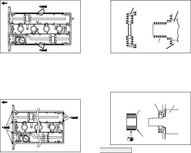
INSTALLATION SERVICE POINTS >>A<< CAMSHAFT SPROCKET BOLT INSTALLATION
Tighten the camshaft sprocket bolt to 88 ± 10 N m while preventing the camshaft from rotation using a wrench fitted on the hexagonal portion of the camshaft.
>>B<< ENGINE SUPPORT BRACKET INSTALLATION
>>C<< SEMICIRCULAR PACKING INSTALLATION
1.Remove thoroughly the old sealant and FIPG remaining on the semicircular packing, cylinder head, and rocker cover.
AK202860AB
2.Apply sealant to the surface indicated in the drawing of the semicircular packing.
Specified sealant:
3M ATD No.8660 or equivalent
3.Install the semicircular packing on the cylinder head.
|
10 mm |
||
|
10 mm |
||
|
Semicircular |
||
|
packing |
Cylinder head |
AK304411AB |
4.Apply sealant to the area indicated in the drawing of the semicircular packing and cylinder head.
Specified sealant:
3M ATD No.8660 or equivalent
1.Remove thoroughly the old sealant remaining on the indicated bolt and in its hole.
2.Coat the bolt with sealant, then install and tighten it.
Specified sealant:
Mitsubishi Genuine Part No.MD970389 or equivalent
|
11D-20 |
ENGINE OVERHAUL <4G63-Turbo> |
|
TIMING BELT |
>>D<< ROCKER COVER/ROCKER COVER GASKET «A» INSTALLATION
|
Timing belt side |
|
AK304203AB |
1.Apply beads of FIPG on the surfaces of the rocker cover indicated in the drawing.
Specified sealant:
Mitsubishi Genuine Part No.MD970389 or equivalent
2.Install the rocker cover gasket «A» on the rocker cover before the FIPG hardens.
|
Timing belt side |
|
AK304204AB |
3.Apply beads of FIPG to the surfaces of the rocker cover indicated in the drawing.
Specified sealant:
Mitsubishi Genuine Part No.MD970389 or equivalent
4.Install the rocker cover on the cylinder head before the FIPG hardens.
>>E<< CRANKSHAFT SPROCKET «B» INSTALLATION
Sprocket «B»
Crankshaft
|
Degrease |
|
|
Front case |
AK301828AD |
Clean and then degrease the crankshaft sprocket «B» and the sprocket fitting surface of the crankshaft.
NOTE: Degreasing is necessary to prevent lack of frictional coefficient between the mating surfaces.
>>F<< SPACER INSTALLATION
Counter
Oil seal balance shaft
Spacer
Chamfered
AK301298AD

 CAUTION
If the spacer is opposite in direction to that shown in the drawing when installed, it will damage the oil seal lip.
1.Smear slightly oil on the outer surface of the spacer that comes into contact with the oil seal.
2.Install the spacer with the chamfered end toward the oil seal.
![]()
|
ENGINE OVERHAUL <4G63-Turbo> |
11D-21 |
||
|
TIMING BELT |
|||
|
>>G<< COUNTERBALANCER SHAFT |
Tension section of belt |
||
|
SPROCKET INSTALLATION |
Tensioner «B» |
||
|
Timing |
|||
|
belt «B» |
|||
|
MD998785 |
|||
|
Tensioner «B» |
|||
|
centre |
Mounting bolt centre |
||
|
AK305992AC |
|
3. Make sure that the tensioner «B» center is |
||
|
AK300138AD |
positioned as shown in the drawing relative to the |
|
|
1. Use the special tool Sprocket stopper |
mounting bolt center. |
|
|
(MD998785) as shown in the drawing to prevent |
||
|
the counterbalancer shaft sprocket from rotating. |
||
|
2. Tighten the sprocket mounting bolt to 45 ± 3 N m. |
||
|
>>H<< TIMING BELT «B» INSTALLATION |
||
|
Timing |
||
|
marks |
AK304436AB |
|
|
4. Lift the tensioner «B» with fingers to move it in the |
||
|
Timing |
direction of the arrow until the tension section of |
|
|
marks |
the timing belt becomes taut. While keeping the |
|
|
tensioner «B» in this position, tighten its bolt. |
||
|
AK305991AC |
NOTE: When the bolt is tightened, prevent the |
|
|
1. Align the timing marks on the crankshaft sprocket |
tensioner «B» shaft from turning. If the shaft turns, |
|
|
the belt will be overtightened. |
||
|
«B» and counterbalancer shaft sprocket with the |
5. Make sure that the timing marks on the oil pump |
|
|
corresponding timing marks on the oil pump case. |
||
|
case and those of the sprockets are all aligned |
||
|
2. Install the timing belt «B» on the crankshaft |
||
|
with each other. |
||
|
sprocket «B» and counterbalancer shaft sprocket. |
||
|
There should be no slack in the tension section of |
5 – 7 mm |
|
|
the belt. |
||
|
AK305993AC |
6.Push a central point of the timing belt «B» tension section lightly with an index to see if it deflects 5 − 7 mm.
 Loading…
The complete 89-93 4G63 Engine Manual.

ENGINE4G61, 4663, 4664
<1992>CONTENTS
IBRACKET . . . . . . . . . . . . . . . . . . . . .,. . . . . . . . . . . . . . . . . . . . . . . . . . . . . . . . . . . . . . . 107CAMSHAFTS AND ROCKERARMS — DOHC . . . . . . . . . . . . . . . . . . . . . . . . . . . . . . . . . . . . . . . . . . . . . . . . . . . . 71CRANKSHAFT, FLYWHEEL ANDDRIVE PLATE . . . . . . . . . . . . . . . . . . . . . . . . . . . . . . . . . . . . . . . . . . . . . . . . . . . . . . . . 102CYLINDER HEAD AND VALVES — SOHC . . . . . . . . 74CYLINDER HEAD AND VALVES — DOHC . . . . . . . . 80EXHAUST MANIFOLD ANDWATER PUMP . . . . . . . . . . . . . . . . . . . . . . . . . . . . . . . . . . . . . . . . . . . . . . . . . . . . 59FRONT CASE, SILENT SHAFT ANDOIL PAN . . . . . . . . . . . . . . . . . . . . . . . . . . . . . . . . . . . . . . . . . . . . . . . . . . . . . . . . . . . . . . . . 85FUEL AND EMISSION CONTROL PARTS . . . . 46GENERAL INFORMATION . . . . . . . . . . . . . . . . . . . . . . . . . . . . . . . . 2GENERAL SPECIFICATIONS . . . . . . . . . . . . . . . . . . . . . . . . . . . . 8
GENERATOR AND IGNITIONSYSTEM — SOHC …………………………………………GENERATOR AND IGNITIONSYSTEM — DOHC ………………………………………… 26INTAKE MANIFOLD …………………………………….. 56PISTON AND CONNECTING ROD ……………….. 95ROCKER ARMS AND CAMSHAFT- SOHC …. 66SPECIAL TOOLS ……………………………………………. 20SEALANT ………………………………………………………. 19SERVICE SPECIFICATIONS ………………………….. 10THROTTLE BODY ………………………………………… 50TIMING BELT — SOHC …………………………………. 28TIMING BELT — DOHC . ………………………………… 36TORQUE SPECIFICATIONS ………………………….. 16TURBOCHARGER ………………………………………… 63

IIC-2 466 ENGINE <1992> — General Information
GENERAL INFQRMATION IENGINE SECTIONAL VIEW — SOHC
6EN0313
TSB Revision
. I

4G6 ENGINE <1992> — General Information
6EN0314
TSB Revision I

IIC-4 466 ENGINE <1992> — General Information
,NGlNE SECTIONAL VIEW — DOHC
TSB Revision

6EN0244
TSB Revision \

IIC-6 466 ENGINE <1992> — General Information
ENGINE LUBRICATION SYSTEM — SOHC
Rocker shaft\
Camshaft
Oil pressureswitch
\
rankshaft
6LUOO39
ENGINE LUBRICATION SYSTEM — DOHC
Camshaft
Oil cooler
Oil coolerby-pass valve
Silent shaft&I)
lressure switch
Oil puml ’
Crankshaft
I1 t- A/ ‘Silent shaft
TSB Revision6LUOO55
I-

4G6 ENGINE <1992> — General Information
ENGINE LUBRICATION SYSTEM DOHC-TURBO
Oil
To
Camshaft
ee EIeSilent shaft
From thermostat casen
filter \ K Oil cooler /
+ I!IJ,
— To turbocharger
water inlet pipe i I41 Key=
Oil pressure sw&h
Oil pump /(k,/ ‘Silent shaft Crankshaft-7
6LUOW6
1 TSB Revision 1

IIC-8 -4G6 ENGINE <1992> — General Specifications
GENERAL SPECIFICATIONS4G63 SOHC
TypeNumber of cylindersCombustion chamberTotal displacement cm3 (cu. in.)Cylinder bore mm (in.)Piston stroke mm (in.)Compression ratioValve timing
( ): camshaft identification markIntake valve
Open BTDCClose ABDC
Exhaust valveOpen BBDCClose ATDC
Lubrication systemOil pump typeCooling systemWater pump typeEGR systemInjector type and numberInjector identification markThrottle position sensorClosed throttle position switch
4664 SOHC
In-line OHV, SOHC4Compact type1,997 (121.9)85 (3.35)88 (3.46)8.5
(AR)
19″57”
57”19” 1Pressure feed, full-flow filtrationInvolute gear typeWater-cooled forced circulationCentrifugal impeller typeSingle typeElectromagnetic 4N210HVariable resistor typeContact type, incorporated in idle speed control motor
TypeNumber of cylindersCombustion chamberTotal displacement cm3 (cu. in .ICylinder bore mm (in.)Piston stroke mm (in.)Compression ratioValve timing
( ): camshaft identification markIntake valve
Open BTDCClose ABDC
Exhaust valveOpen BBDCClose ATDC
Lubrication systemOil pump typeCooling systemWater pump typeEGR systemInjector type and numberInjector identification markThrottle position sensorClosed throttle position switch
1 In-line OHV, SOHC
14Compact type2,350 (143.4)86.5 (3.35)100 (3.46)8.5
0) (AR)
20” 19”64” 57”
64” 57”20” 19”Pressure feed, full-flow filtrationInvolute gear typeWater-cooled forced circulationCentrifugal impeller typeSingle typeElectromagnetic 4N275HVariable resistor typeContact switch type, incorporated in idle speed control motor-TRUCKMovable contact type, incorporated in throttle position sensor — EXPO
TSB Revision

4G6 ENGINE <1992> — General Specifications 1 TG94661 DOHC
TypeNumber of cylindersCombustion chamberTotal displacement cm3 (cu. in.)Cylinder bore mm (in.)Piston stroke mm (in,)Compression ratioValve timing
( ): camshaft identification markIntake valve
Open BTDCClose ABDC
Exhaust valveOpen BBDCClose ATDC
Lubrjcatlon systemOil pump typeCooling systemWater pump typeEGR systemInjector type and numberInjector identification markThrottle position sensorClosed throttle position switch
4663 DOHC
,
I
1
L
fI1(:EELC
TypeNumber of cylindersCombustion chamberTotal displacement cm3 (cu. in.)Cylinder bore mm (in.)Piston stroke mm (in.)Compression ratio
valve timing( ): camshaft identification mark
Intake valveOpen BTDCClose ABDC
Exhaust valveOpen BBDCClose ATDC
Lubrication system3il pump typeCooling systemJVater pump typeEG R systemnjector type and numbernjector identification mark
Non-turboTurbo for GALANT/ECLIPSE M/TTurbo for ECLIPSE A/T
Throttle position sensorClosed throttle position switch
piiEzGi
In-line OHV, DOHC4Pentroof type1,595 (97.3)82.3 (3.24)75 (2.95)3.2
. .
33 (F)
16” 26”$8” 38”
13 53”17” 7”‘ressure feed, full-flow filtrationnvolute gear typeWater-cooled forced circulationIentrifugal impeller type;ingle typeilectromagnetic 43275Hrariable resistor typeIontact type
In-line OHV, DOHC4Pentroof type1,997(121.9)85 (3.35)88 (3.46)7.8 or 9.0(Specs. varies according to engine model)
IA) (B.C)
26” 21”46” 43”
55” 57”3” 15”Pressure feed, full-flow filtrationInvolute gear typedater-cooled forced circulationCentrifugal impeller typeSingle type!lectromagnetic 4
(D.C) (EA
21” 16”51” 48”
57” 55”15” 9”
‘J240H345OL33901.dariable resistor typeContact type

IIC-10 4G6 ENGINE <1992> — Service Specifications
SERVICE SPECIFICATIONSmm (in.)
Cylinder head — SOHCFlatness of gasket surfaceGrinding limit of gasket surface* Total resurfacing depth of both cylinder head
and cylinder block.Overall heightOversize rework dimensions of valve guide hole(both intake and exhaust)
0.05 (.002)0.25 (.OlO)0.50 (.020)
Oversize rework dimensions of intake valveseat ring hole
0.30 f.012) 4G634G64
0.60 (024) 46634664
Oversize rework dimensions of exhaust valveseat ring hole
0.30 l.012) 46634664
0.60 (.012) 4G634G64
Cylinder head — DOHCFlatness of gasket surfaceGrinding limit of gasket surface* Total resurfacing depth of both cylinder head
and cylinder block.Overall height,Oversize rework dimensions of valve guide hole(both intake and exhaust)
0.05 (.002)0.25 (.OlO)0.50 (020)
Oversize rework dimensions of intake valveseat ring hole
0.30 i.012)0.60 (024)
Oversize rework dimensions of exhaust valveseat ring hole
0.30 l.012)0.60 (.024)
Standard Limit
0.05 (.0020) 0.2 (008)*0.2 (008)
_I89.9 — 90.1 (3.539 — 3.547)
I.
I-13.05- 13.07 (.5138- .5146)13.25-13.27(.5217-.5224) i13.50 — 13.52 (5315 — .5323)
44.30 — 44.33 (1.7441 — 1.7453)47.30 -47.33 (3.8622 — 1.8634)44.60 — 44.63 (1.7559 — 1.7571)47.60 -47.63 (1.8740 — 1.8752)
4’
38.30 — 38.33 (1.5079 — 1.5091)40.30 — 40.33 (1.5866 — 1.5878) “J38.60 — 38.63 (1.5197 — 1.5209)40.60 — 40.63 (1.5984 — 1.5996) ~
0.05 (0020) 0.2 (008)“0.2 (008)
131.9-132.1 (5.193-5.201)
12.05-12.07(.4744-.4752) )12.25 — 12.27 (4823 — .4831)12.50 — 12.52 i.4921 — .4929) ;
35.30 — 35.33 (1.3898 — 1.3909) c35.60 — 35.63 (1.4016 — 1.4028) -<
33.30 — 33.33 (1.3110 — 1.3122)33.60 — 33.63 (1.3228 — 1.3240)
. .
1
1 TSB Revision

466 ENGINE <1992> — Service Specification3 IWwl
mm (in.)
Camshaft — SOHCIdentification mark: D
Cam height IntakeExhaust
Identification mark: ARCam height Intake
ExhaustNOTE:The camshaft identification mark is stampedon the rear end of the camshaft.Fuel pump driving cam diameterJournal diameterOil clearance
Camshaf t — DOHCIntakeIdentification mark: A,D
Cam heightdentification mark: B,C,E,F
Cam heightExhaustdentification mark: A
Cam heightdentification mark: C
Cam heightdentification mark E,F
Cam height\lOTE:The camshaft identification mark is stampedIn the rear end of the camshaft.lournal diameterXl clearance
locker arm — SOHC.D.sacker arm-to-shaft clearance
-ash adjuster.eak down testRemarks: Diesel fuel at 15 — 20°C (59 — 68°F)
Standard
42.40 (1.6693)42.40 (1.6693)
44.53 (1.7531)44.53 (1.7531)
38 (1.50)33.94 — 33.95 (1.3362 — 1.3366)0.05 — 0.09 (.0020 — .0035)
35.49 (1.3972)
35.20 (1.3858)
35.20 (1.3858)
35.49 (1.3972)
35.91 (1.3744)
25.95 — 25.97 (1.0217 — 1.0224)0.05 — 0.09 i.0020 — .0035)
18.91 — 18.93 (.7445- .7453)0.01 — 0.04 LOO04 — .0016)
4 — 20 seconds/l mm (.04 in.)
Limit., ;J’ _.
41’.90 (1.6496)41.90 (1.6496)
44.03 (1.7335)44.03 (1.7335)
34.99 (1.3776)
34.70 (1.3661)
34.70 (1.3661)
34.99 (1.3776)
34.41 (1.3547)
011 (.004)
locker shaft — SOHCI.D.Iverall length Intake
Exhaust
18.89 — 18.90 (.7437 — .7441)385.5(15.177)372.5 (14.665)
1 TSB Revision

IIC-12 466 ENGINE c1992> — Service Specifications
mm (in.)
Standard Limit
Valve — SOHCOverall length Intake 4663 109.8(4.321)
4664 106.6 (4.197)Exhaust 4G63 108.7 (4.280)
4664 105.2 (4.142)FStem diameter Intake 7.96-7.98(.3134-.3142)
Exhaust 7.93-7.95 (.3122-.3130)Face angle 45”- 45”30’Thickness of valvehead (margin) Intake 1.2 (047) i 0.7 (02%)
Exhaust 2.0 (.079) 1.5 (.059)Stem-to guideclearance Intake 0.02 — 0.06 (.OOO%- .0024) 0.10 (004)
Exhaust 0.05 — 0.09 (0020 — .0035) 0.15 (006)
Valve — DOHCOverall length Intake 109.5 (4.311)
Exhaust 109.7 (4.319) _I
Stem diameter Intake 6.57 — 6.58 (.2587 — .2591)Exhaust 6.53 — 6.55 (2571 — .2579) /
Face angle 45” — 45”30’Thickness of valvehead (margin) Intake 1 .o (039) 0.7 (02%)
Exhaust 1.5 (.059) 1 .o l.039)Stem-to guideclearance Intake 0.02 — 0.05 (.OOO%- .0020) 0.10 (004)
Exhaust 0.05 — 0.09 (0020 — .0035) 0.15 (006)
Valve spring — SOHCFree height 49.8 (1.961) 48.8 (1.921)~w$nstalled I
N/mm (Ibs./in.) 329/40.4 (73/I ,591)Out-of-squareness 2” or less Max. 4”
Valve spring — DOHCFree height 48.3 (1.902) 47.4 (1.866)k;;hnstalled
N/mm (IbsAn.) 300/40 (66/l .57)Out-of-squareness 1.5” or less Max. 4”
Valve guide- SOHC ‘-;Overall length Intake 47 (1.85)
Exhaust 52 (2.05)I.D. 8.00 — 8.02 (3150 — .3157)3.D. 13.06- 13.07 (.5142- .5146)Service size 0.05(.002),0.25(.010),0.50(.020)oversizePress-in temperature Room temperature
1 TSB Revision

4G6 ENGINE <1992> — Service Snebifications
mm (in.)
Valve guide — DOHCOverall length
I.D.O.D.Service sizePress-in temperature
Va Ive seatSeat angleValve contact widthSinkageService size
Si lent shaftJournal diameter
3il clearance
Standard Limit
45.5 (1.791)50.5 (1.988)6.60 — 6.62 (.2598 — .2606)12.06 — 12.07 (.4748 — .4752)0.05 (.002), 0.25 (.OlO), 0.50 (.020) over sizeRoom temperature
43”30’ — 44”0.9 — 1.3 (.035 — .051)
0.2 (.OO%)0.3 (.012), 0.6 (.024) over size
41.96 — 41.98 (1.6520 — 1.6528)40.95 — 40.97 (1.6122 — 1.6130)18.47 — 18.48 (.7272 — 0.7276)40.95 — 40.97 (1.6122 — 1.6130)0.03 — 0.06 LOO1 2 — .0024)0.05-0.09 (.0020-.0036)0.02 — 0.05 (.OOO% — .0020)0.05 — 0.09 (.0020- .0036)
‘iston — SOHCI.D. 4663
4G64Won to cylinder clearanceservice size
84.97 — 85.00 (3.3453 — 3.3465)86.47 — 86.50 (3.404 — 3.4055)0.02-0.04(.0008-.0016)0.25 LOlO), 0.50 (.020), 0.75 (.030),1 .OO f.039) over size
Won — DOHCI.D. 4G61
4663 — Non-turbo4G63 -Turbo
‘iston to cylinder clearanceNon-turboTurbo
;ervice size
82.27 — 82.30 (3.2390 — 3.2401)84.97 — 85.00 (3.3453 — 3.3465)84.96 — 84.99 (3.3449 — 3.3461)
0.02 — 0.04 (.OOO% — .0016)0.03 -0.05 (.0012 — .0020)0.25 (.OlO), 0.50 (.020), 0.75 (.030).1 .OO (.039) over size
1 TSB Revision 1

466 ENGINE <1992> — Service Specifications
mm (in.)
Piston ring — SOHCEnd gap
Ring-to-ring grooveclearance
Service size
No. 1 ringNo. 2 ring
46634664
Oil ring
No. 1 ringNo. 2 ring
Standard
0.25 — 0.40 LOO98 — .0157)
0.20 — 0.35 LOO79 — .0138)0.20 — 0.40 LOO79 — .0157)0.20 — 0.70 LOO79 — .0276)
0.03 — 0.07 LOOI 2 — .0028)0.02 — 0.06 (.OOO% — .0024)0.25 (.OlO), 0.50 (.020), 0.75 (.030),1 .OO (.039) over size
Limit
0.8 (031)
0.8 (.031)0.8 (.031)1 .o (.039)
0.1 (.004)0.1 (004)
Piston ring — DOHCEnd gap
Ring-to-ring grooveclearance
Service size
No. 1 ringNo. 2 ring
4G614663
Oil ring
No. 1 ringNo. 2 ring
0.25 — 0.40 LOO98 — .0157)
0.35 — 0.50 (013% — .0197)0.45 — 0.60 f.0177 — .0236)0.20 — 0.70 LOO79 — .0276)
0.03 — 0.07 (.0012 — .0028)0.03 — 0.07 LOO1 2 — .0028)0.25 LOlO), 0.50 (.020), 0.75 (.030),1 .OO (.039) over size
0.8 (031)
0.8 (.031)0.8 (031)1 .o f.039)
0.1 (004)0.1 (004)
Piston pin3.D.Press-in load N (Ibs.)press-in temperature
Connecting rod3ig end center-to-small end center length3endrwist3ig end side clearance
Crankshaftfnd playJournal O.D.‘in O.D.ht-of-roundness and taper of journal and pinkcentricity of journalIii clearance of journalII clearance of pin
21 .OO — 21 .Ol (826% — .8272)7,500 — 17,500 (1,653 — 3,858)Room temperature
149.9 — 150.0 (5.902 — 5.906)0.05 (002)0.1 (004)O.lO-0.25(.0039-.0098)
0.05-0.18 (.0020- .0071)56.98 — 57.00 (2.2433 — 2.2441)44.98 — 45.00 (1.7709 — 1.7717)Max. 0.01 (.0004)Max. 0.02 (.OOO%)0 . 0 2 — (.OOO% -0.05 .0020)0.02 — (.OOO% -0.05 .0020)
:
0.4 (016):!
0.25 (.0098)
0.1 (004)0.1 (004)
TSB Revision

466 ENGINE t1992> — Service Sbecifications
Cylinder blockCylinder I.D. 4G61
46634664
Flatness of gasket surfaceGrinding limit* Total resurfacing depth of both cylinder head
and cylinder block.Overall height 4G61
46634G64
Oil pumpSide clearance
Drive gearDriven gear
3rive beltIeflection
V-ribbed type belt New beltUsed belt
V type belt-ension
V-ribbed type belt New belt N (Ibs.)Used belt N (Ibs.)
Xl cooler by-pass valveIimension (L)ly-pass hole closing temperature37 — 103°C (207 — 217°F) or more)
Standard
82.30 — 82.33 (3.2402 — 3.2413)85.00 — 85.03 (3.3465 — 3.3476)86.50 — 86.53 (3.4055 — 3.4067)0.05 (0020)
274.9 — 275.1 (10.823 — 10.831)283.9-284.1 (11.177-11.185)289.9-290.1 (11.413-11.421)
0.08 — 0.14 (0031 — .0055)0.06 — 0.12 (0024 — .0047)
7.5 — 9.0 (.30 — .35)8.0 (32)7.0 — 10.0 (28 — .39)
500 — 700 (11 O’- 154)400 (88)
34.5 (1.358) — normal temperature40 (1.57) or more
_’ .’ mm (ir
Limit
0.1 (004)”*0.2 (.008)
ejectorIoil resistance
Non — turbo QT u r b o R
Jle speed control motor:oil resistance CR
Ale air control motor:oil resistance Cn
Ale speed control motor posi t ion sensorSOHC engine for GALANTITRUCKlesistance klR
13 — 16 at 20°C (68°F)2 — 3 at 20°C (68°F)
5 — 35 at 20°C (68°F)
28 — 33 at 20°C (68°F)
4 — 6
NOTE0.D.; OuteL piameterI.D.: Inner DiameterU.S.: Undersize Diameter
TSB Revision

IIC-16 4G6 ENGINE <1992> — Torque Specifications
TORQUE SPECIFICATIONS
Generator and igni t ion system — SOHCCooling fan boltWater pump pulley bolt — Engine without cooling fanWater pulley bolt — Enginepump with cooling fanGenerator brace boltGenerator mounting boltGenerator pivot nutCrankshaft pulley boltSpark plugDistributor nutIgnition coil boltIgnition power transistor nut
Generator and igni t ion system — DOHCW a t e r p u l l e y b o l tpumpGenerator brace boltGenerator mounting boltGenerator pivot nutCrankshaft pulley boltCenter cover boltSpark plugIgnition coil boltIgnition power transistor bol tCrankshaft position sensor nut
Timing bel t — SOHCTensioner boltTensioner spacerOil sprocket nutpumpCrankshaft sprocket boltTensioner “B” boltSilent shaft sprocket bolt, rightEngine supports bracket bolt, leftCamshaft sprocket bolt
riming belt- DOHCTensioner pulley boltTensioner arm boltIdler pulley bolt3il pump sprocket nutCrankshaft sprocket boltTensioner “B” boltSilent shaft sprocket bolt, rightqocker cover bolt3amshaft sprocket boltEngine support bracket, left
Nm
11
9 .;1114 f24232525111418
91424232532524111 9.i
49 :4955120194636 :90
:492238 j55120 “.19463 19036
ft .1b.s.
87810171718188IO13
7IO17171821817814
3535408714332665
35162740871433226526
1 TSB Revision

4G6 ENGINE <1992> — Toraue SDecifications IIC-17
Fuel and emission partsEGR valve boltThrottle body stay nut — DOHCThrottle body bolt — SOHCThrottle body bolt — DOHCFuel regulator boltpressureFuel rail bolt
Throttle bodyThrottle position sensor boltIdle speed control motor boltIdle air control motor bolt
Intake manifoldIntake manifold bolt and nutIntake manifold nut — DOHCIntake manifold stay bolt — SOHCIntake manifold stay bolt — DOHCIntake manifold plenum bolt and nutIntake manifold plenum stay boltWater outlet fitting boltEngine coolant temperature gauge unitEngine coolant temperature sensorThermostat case nut
Exhaust manifold and water pumpOil level guide boltgaugeHeat protector bolt
GALANT AND EXPOTRUCK
Exhaust manifold nut — SOHCExhaust manifold nut — DOHCEngine hanger bolt — DOHCAir outlet fitting boltTurbocharger bolt and nutExhaust fitting boltWater inlet pipe boltWater boltpumpWater pipe “A“ and “B” eye boltWater pipe “A“ boltWater pipe “B” flare nut
Water pipe boltM8M6
Oil return pipe bolt
Oil pipeCylinder head sideTurbocharger side
Nm ftlbs.
19 1419 1412 919 149 712 9
2 1.43.5 2.53.5 2.5
18 1336 2622 1628 2018 1318 1319 1411 830 2218 13
60 43
14 1030 2218 1328 2014 1019 1460 4360 4314 1024 1743 3111 845 33
14 1011 89 7
17 1231 22
1 TSB Revision I

TurbochargerTurbocharger waste gate actuator bolt
Rocker arms and camshaf t- SOHCRocker cover boltBearing cap bolt
M8x25M8x65
Camshafts and rocker arms — DOHCBearing cap boltOil delivery body bolt
Cyl inder head and valves — SOHCCylinder head bolt
Cyl inder head and valves- DOHCCylinder head bolt
Front case, si lent shaft and oi l panOil cooler boltDrain plugOil boltpanOil screen bolt and nutOil sprocket boltpumpPlugSilent shaft, left flange boltOil filter bracket boltFront case bolt
M8Ml0
Oil cooler by-pass valveOil switchpressureOil unitpressure gaugeRelief plugOil cover boltpumpCheck valve
Piston and connect ing rodConnecting rod cap nut
Crankshaft , flywheel and drive plate
+wheel boltIrive plate bolt3il seal case bolt3earing cap bolt — SOHC3earing cap bolt — DOHC
Nm ftlbs.
r12 9
’6 4!.
24 1720 14
20 ? 1411 (’ 8
;
95 69
: /110 ;( 80
43 : 3140 : 297 : 519 -’ 1455 ; 4024 17
37 t 2719 ! 14
24 -.~ 1731 2255 4010 755 :: 4045 3317 ! 1233 24
52 .?& 38
135 98135 9811 853 3868 49
IIC-18 466 ENGINE <1992> — Torque Specifications
TSB Revision

4G6 ENGINE <1992> — Torque Specifications / Sealant 1 IC-19
BracketLeft and right engine support bracket bolt 45 33Roll stopper bracket bolt, front 65 47Roll stopper bracket bolt, rear 120 87Engine support bracket bolt, front 60 43Exhaust pipe support bracket bolt 36 26
SEALANT
Nm ft.lbs.
Rocker coverSemi-circular packingOil pan gasket
Engine coolant temperature gauge unitEngine coolant temperature sensor
Oil pressure switchOil pressure gauge unit
Specified sealant Quantity
3M ATD Part No. 8660 or equivalent As required3M ATD Part No. 8660 or equivalent As requiredMITSUBISHI GENUINE PART As requiredMD970389 or equivalent3M ATD Part No. 8660 or equivalent As required3M Nut Locking Part No. 4171 As requiredor equivalent3M ATD Part No. 8660 or equivalent As required3M ATD Part No. 8660 or equivalent As required
1 TSB Revision I

11 c-20 466 ENGINE <1992> — Special Tools
SPECIAL TOOLSTool Number and
tool nameSupersession
MB990767 M 8990767-01End yoke holder Use with MIT308239Use withMD9987 19
MD998051 MD998051-01Cylinder head boltwrench
M D998162Plug wrench
MD9981 62-01
M D998285 M D998285-0 1Crankshaft frontoil seal guide
MD998371Silent shaftbearing puller
MD998371-01Use with MIT304204
M D998372Silent shaftbearing puller
M D998372-01Use with MIT304204
cQ Q
MD998374 M D998374-0 1Bearing installerstopper
MD998375 MD998375-01Crankshaft frontoil seal installer
MD998376 MD998376-01Crankshaft rear Use withoil seal installer MB990938-01
Application
Holding camshaft spr&ket when looseningor torquing bolt.For SOHC engine only
Loosening or torquing of cylinder head bolt
Removal and installation of front case capplug
Installation of crankshaft front oil seal
Removal of silent shaft rear
Removal of silent shaft rear
Removal and installation of rear bearing
nstallation of crankshaft front oil seal
nstallation of crankshaft rear oil seal
1 TSB Revision

4G6 ENGINE <1992> — Special Tools
MD998713 MD998713-01Camshaft oil sealinstaller
MD99871 9Pulley holdingpins (2)
M IT308239 Holding camshaft sprocket when looseningor torquing boltFor SOHC engine only
MD998727Oil pan remover
Removal of oil pan
MD998729 MD998729-01 Installation of valve stem sealValve stem seal For SOHC engine onlyinstaller
TSB Revision

IIC-22 4G6 ENGINE <1992> — Special Tools
M D998779Sprocket stopper
Holding silent shaft sprocket
MD998780Piston pinsetting tool
M IT2 16941 Removal and installation of piston pin
MD998781Flywheel stopper
Holding flywheel
TSB Revision

466 ENGINE <1992> — Generator and Ignition System — SOHC
GENERATOR AND IGNITION SYSTEM — SOHCREMOVAL AND INSTALLATION
1 IC-23
25 Nm
14 NmlOft.lbs. -1
Q0I
23 Nm17 ft.lbs.
I14 Nm I10 ftlbs. 24 Nm
17 ftlbs. 54 I
!!!?a RWD
9 Nm**7 ftlbs. Removal steps11 Nm***8 ft.lbs. *B4 1. Drive belt
2. Cooling fan***3. Fan clutch***4. Water pump pulley”5. Water pump pulley6. Generator brace7. Generator8. Crankshaft pulley9. Spark plug cable
10. Spark plug11. High tension cable
NOTE *A4 12. Distributor* : Engine with power steering 13. Ignition coil** : Engine with cooling fan 14. Ignition power transistor***: Engine without cooling fan
6EN0631
TSB Revision 1

1 IC-24 466 ENGINE <1992> — Generator and Ignition System — SOHC
1ELOOlf
INSTALLATION SERVICE ,POINTSr)A4 DISTRIBUTOR INSTALLATION(1) Align the marks put at the time of disassembly, and install
the gear to the distributor shaft.
(2) When aligning the driven gear’s mating mark and thehousing’s mating marks, make the combination so thatnotch “A” at the shaft end is at the position shown in thefigure, and then align the spring pin holes and drive in a newspring pin.CautionDrive in the spring pin so that the slit is at a right anglerelative to the shaft.
*64 DRIVE BELT TENSION ADJUSTMENTADJUSTER TYPE(1) Adjust the belt deflection to the standard value. Turn the
adjusting bolt clockwise to increase the belt tension andturn the adjusting bolt counterclockwise to decrease thebelt tension.Standard value: ’
V-ribbed type beltNew belt 7.5 — 9.0 mm (30 — .35 in.)Used belt 8.0 mm (32 in.)
V-type belt 7.0 — 10.0 mm (28 — .39 in.)
When using a tension gauge for V-ribbed belt only.Standard value:
New belt 500 — 700 N (110 — 154 Ibs.)Used belt 400 N (88 Ibs.)
(2) Tighten the lock bolt to the specified torque.(3) Tighten the nut for the pivot bolt to the specified torque.
TSB Revision

4G6 ENGINE <1992> — Generator and Ignition Svstem — SOHC 1 ICE-25
Waterpulley
Crankshaft pulley6EN0593
Alternpulley
/‘, Water pump pulley
6EN059E
BRACE BOLT TYPE(1) Move the generator to adjust the belt deflection to the
standard value.Standard value:
V-ribbed type beltNew belt 7.5 — 9.0 mm (.30 — .35 in.)Used belt 8.0 mm (.32 in.)
V-type belt 7.0 — 10.0 mm (.28 — .39 in.)When using a tension gauge for V-ribbed belt only.Standard value:
New belt 500 — 700 N (110 — 154 Ibs.)Used belt 400 N (88 Ibs.)
(2) Tighten the brace bolt to the specified torque.(3) Tighten the nut for the pivot bolt to the specified torque.
TSB Revision

11 C-26 4G6 ENGINE <1992> — Generator and Ignition System — DOHC
GENERATOR AND IGNITION SYSTEM — DOHCREMOVAL AND INSTALLATION
18 ft.lbs.19 Nm14 ftlbs.
11 Nm8 ft.lbs.
5 23 NmI
14 Nm10 ft.lbs. 24 Nm I17 ftlbs.
24 Nm17 ftlbs.
Removal stepseB4 1. Drive belt
2. Water pump pulley3. Water pump pulley
(For driving power steering pump)4. Generator brace5. Generator6. Crankshaft pulley7. Center cover8.-Spark plug cable9. Spark plug
10. Ignition coil11. Ignition power transistor
#A4 12. Crankshaft position sensor13. O-ring
11
TSB Revision I

466 ENGINE <1992> — Generator and Ignition System — DOHC IIC-27INSTALLATION SERVICE POINTS#A4 CRANKSHAFT POSITION INSTALLATION(1) Turn the crankshaft so that the No. 1 cylinder is at top dead
center.(2) Align the punch mark on the crankshaft position sensor
housing with the notch in the plate.(3) Install the crankshaft position sensor on the cylinder head.
eB4 DRIVE BELT TENSION ADJUSTMENTRefer to “I)B4 DRIVE BELT TENSION ADJUSTMENT” onpage 11 C-24.
1 TSB Revision II I

11 C-28 4G6 ENGINE <1992> — Timing Belt — SOHC
TIMING BELT — SOHCREMOVAL AND INSTALLATION
EE N m
iF — —~~~” 87 ft.lbs.
1” . . . . .
40 ft.lbs.
18
Removal steps1. Timing belt front upper cover2. Timing belt front lower cover
(IAI) eH4 3. Timing belt#Gg 4. Tensioner spring*Gg 5. Tensioner
QBg eF4 6. Oil pump sprocket81: $E4 7. Crankshaft bolt
8. Crankshaft sprocket9. Flange
10. Tensioner “B”c$ErJ eD4 11. Timing belt “B”(IFI) #C4 12. Silent shaft sprocket, right
#B4 13. Spacer($0 14. Crankshaft sprocket “B”
15. Engine support bracket, left(IHI) *A4 16. Camshaft sprocket bolt
17. Camshaft sprocket18. Timing belt rear cover
6EN0633
TSB Revision

4G6 ENGINE <1992> — Timing Belt — SOHC IIC-29
6EN0563 6EN056~
REMOVAL SERVICE POINTSQAo TIMING BELT REMOVAL(1) Mark the belt running direction for reference in reinstalla-
tion.NOTE(1) Water or oil on the belt shortens its life drastically, so
the removed timing belt, sprocket, and tensioner mustbe free from oil and water. These parts should not bewashed. Replace parts if seriously contaminated.
(2) If there is oil or water on each part, check the front caseoil seals, camshaft oil seal and water pump for leaks.
QBQ OIL PUMP SPROCKET REMOVAL(1) Remove the plug on the left side of the cylinder block.(2) Insert a Phillips screwdriver [shank diameter 8 mm (31 in.)]
to block the left silent shaft.(3) Remove the nut.(4) Remove the oil pump sprocket.
@@ CRANKSHAFT BOLT REMOVAL(1) Using the special tool, hold the drive plate or flywheel.(2) Remove the crankshaft bolt.
@I) CRANKSHAFT SPROCKET REMOVAL
QEo TIMING BELT “B” REMOVAL(1) Make a mark on the back of the timing belt indicating the
direction of rotation so that it may be reassembled in thesame direction if it is to be reused.NOTE(1) Water or oil on the belt shortens its life drastically, so
the removed timing belt, sprocket, and tensioner mustbe free from oil and water. These parts should not bewashed. Replace parts if seriously contaminated.
(2) If there is oil or water on each part, check the front caseoil seals, camshaft oil seal and water pump for leaks.
TSB Revision

4G6 ENGINE <1992> — Timing Belt — SOHC
\
&00 B
000
8EN006Z
Peeling Cracks
Cracks 1 EN0249
(IF0 SILENT SHAFT SPROCKET REMOVAL
QGt) CRANKSHAFT SPROCKET “B” REMOVAL
aHo CAMSHAFT SPROCKET BOLT REMOVAL
INSPECTIONTIMING BELTReplace belt if any of the following conditions exist.(1) Hardening of back rubber — the back side is glossy without
resilience and leaves no indent when pressed with finger-nail.
(2) Cracks on rubber back.(3) Cracks or peeling of canvas.(4) Cracks on rib root.(5) Cracks on belt sides.
1 TSB Revision

4G6 ENGINE <1992> — Timing Belt — SOHC 1 IC-31
Roundededge
Abnormal wear(Fluffy strand)
8EN006;
Rubber exposed
Tooth missingand canvas fiber
8EN006t
Spacer
I7/A%&
/y/7/,
f
Oil seal53\ Silkt
Chamfer shaft b6EN061 E
(6) Abnormal wear of belt sides. The sides are normal if theyare sharp as if cut by a knife.
(7) Abnormal wear on teeth.(8) Missing tooth.
INSTALLATION SERVICE POINTSI)A4 CAMSHAFT SPROCKET BOLT INSTALLATION
I)B4 SPACER INSTALLATION(1) Install the spacer with the chamfered end toward the oil
seal.
I)c4 SILENT SHAFT SPROCKET INSTALLATION
1 TSB Revision I

11 C-32 466 ENGINE <1992> — Timing Belt — SOHC
Center of yxtensioner —
\ -m kP,…*— -L L-Or.
/W 6EN057’
+D4 TIMING BELT “B” ‘INSTALLATION(1) Align timing marks on the crankshaft sprocket “B” and
silent shaft sprocket with the marks on the front caserespectively.
(2) Install the timing belt “B” on the crankshaft sprocket “B”and silent shaft sprocket. There should be no slack on thetension side.
(3) Make sure that the relationship between the tensionerpulley center and the bolt center is as shown in theillustration.
(4) Move the tensioner “B” in the direction of arrow whilelifting with a finger to give a sufficient tension to the tensionside of timing belt. In this condition, tighten the bolt tosecure tensioner “B”. When the bolt is tightened, use careto prevent shaft from turning together. If the shaft is turnedtogether, the belt will be over-tensioned.
(5) Check to ensure that the timing marks on the sprockets andfront case are in alignment.
(6) Press with index finger the center of span on the tensionside of timing belt “B”. The belt must deflect 5 — 7 mm (.20- .28 in.).
+E4 CRANKSHAFT BOLT INSTALLATION(1) Using the special tool, hold the drive plate or flywheel.(2) Install the crankshaft bolt.
TSB Revision

4G6 ENGINE <1992> — Timing Belt — SOHC 1 IC-33
Screwdriver6EN0564
Tensloner — 6EN0555
Timing markfor on-vehicleservice only
I)F4 OIL PUMP SPROCKET INSTALLATION(1) Insert a Phillips screwdriver [shank diameter 8 mm (31 in.)]
through the plug hole on the left side of the cylinder block toblock the left silent shaft.
(2) Install the oil pump sprocket.(3) Apply an appropriate amount of engine oil to the bearing
surface of the nut.(4) Tighten the nut to the specified torque.
I)G4 TENSIONER INSTALLATION(1) Hook the tensioner spring ends to the water pump body
projection and tensioner bracket.(2) Move the tensioner fully toward the water pump and
tighten the bolt and tensioner spacer.
I)H4 TIMING BELT INSTALLATION(1) Align the timing marks on camshaft sprocket and crank-
shaft sprocket with their mating marks.(2) Align the timing mark on the oil pump sprocket with its
mating mark.
Timing mark
/
-/
ilange
Timing mark
CalI/
nshaft sprocket
Crankshaft
6EN0475
1 TSB Revision

IIC-34 4G6 ENGINE <1992> — Timing Belt — SOHC
6EN0563 6EN0564
Tensioner spacer
Timing mark
(3) Remove the plug on the cylinder block and insert a Phillipsscrewdriver [shank diameter 8 mm (.31 in.) ] through thehole (Engine with silent shafts).If it can be inserted as deep as 60 mm (2.4 in.) or more, thetiming marks are correctly aligned. If the inserted depth isonly 20 — 25 mm (.8 — 1.0 in.), turn the oil pump sprocketone turn and realign the timing marks. Then check toensure that the screwdriver can be inserted 60 mm (2.4 in.)or more. Keep the screwdriver inserted until installation ofthe timing belt is finished.
(4) Install the timing belt on the crankshaft sprocket, oil pumpsprocket and camshaft sprocket in that order. There shouldbe no slack on the tension side.
(5) Loosen the tensioner mounting bolt and tensioner spacer.
(6) Turn the crankshaft clockwise by two teeth of camshaftsprocket (or crankshaft sprocket).
(7) Apply force to the tensioner in the direction shown by arrow@I to make the belt engage completely with each sprocket.
1 TSB Revision

4G6 ENGINE <1992> — Timinn Belt — SOHC 1 tc-35
i
—
(8) Tighten the tensioner attaching bolt, then tighten thetensioner spacer.CautionIf the tensioner spacer is tightened first, the tensionerturns as the tensioner spacer is tightened, resulting inan excessive belt tension.
(9) Hold the center of the tension side span of the timing belt(between the camshaft and oil pump sprockets) betweenyour thumb and index finger as shown. Then, make surethat the clearance between the belt back surface and coveris standard value.Standard value: 14 mm (.55 in.)
TSB Revision

WC-36 4G6 ENGINE <1992> — Timing Belt — DOHC
TIMING BELT — DOHCREMOVAL AND INSTALLATION
3Nm2.2 ft.lbs. -fl A
24*? I
e 1 87ft.lbs.
TENO*** : Engine without silent shafts
Engine with silent shafts
’25
Removal steps1. Timing belt front upper cover2. Timing belt front lower cover
(IAIJ eK4 3. Timing belteJ4 4. Tensioner pulley
5. Tensioner arm#I4 6. Auto tensioner
7. Idler pulley(~Brj +H4 8. Oil pump sprocket$I$ eG4 9. Crankshaft sprocket bolt
10. Crankshaft sprocket11. Flange12. Spacer*13. Tensioner “B”**
OEo eF4 14. Timing belt “B”“”(IFO eE4 15. Silent shaft sprocket**
+D4 16. Spacer**4GO 17. Crankshaft sprocket “B”**
I)C4 18. Rocker cover#B4 19. Semi-circular packing
(IHO *A4 20. Camshaft sprocket bolt21. Camshaft sprocket22. Engine support bracket23. Timing belt rear right cover24. Timing belt rear left upper cover25. Timing belt rear left lower cover
TSB Revision I

466 ENGINE <1992> — Timing ,Felt — DOHC IIC-37REMOVAL SERVICE POINTSOAi) TIMING BELT REMOVAL(1) Make a mark on the back of the timing belt indicating the
direction of rotation so that it may be reassembled in thesame direction if it is to be reused.NOTE(1) Water or oil on the belt shortens its life drastically, so
the removed timing belt, sprocket, and tensioner mustbe free from oil and water. These parts should not bewashed. Replace parts if seriously contaminated.
(2) If there is oil or water on each part, check the front caseoil seals, camshaft oil seal and water pump for leaks.
OBo OIL PUMP SPROCKET REMOVAL (ENGINE WITHSILENT SHAFTS)
Refer to “@o OIL PUMP SPROCKET REMOVAL” on page11 c-29.
of@ CRANKSHAFT BOLT REMOVAL(1) Using the special tool, hold the drive plate or flywheel.(2) Remove the crankshaft bolt.
ODo CRANKSHAFT SPROCKET REMOVAL
~EI) &hdd~l~ELT “B” REMOVAL (ENGINE WITH SILENT
Refer to “OEO TIMING BELT “B” REMOVAL” on page11 c-29.
TSB Revision I

1 IC-38 4G6 ENGINE <1992> — Timing Belt — DOHC
OF0 SILENT SHAFT SPROCKET REMOVAL
QGo CRANKSHAFT SPROCKET “B” REMOVAL
(IHO CAMSHAFT SPROCKET REMOVAL(1) Using a wrench, hold the camshaft at its hexagon (between
the No. 2 and No. 3 journals) and remove the camshaftsprocket bolt.CautionLocking the camshaft sprocket with a tool damages thesprocket.
(2) Remove the camshaft sprockets.
INSPECTIONTIMING BELTSRefer to “INSPECTION” on page 1 IC-29.
TSB Revision

4G6 ENGINE <1992> — Timina Belt — DOHC IX-39
a
-1
00
‘il;
0
12mm( 47 in.)
6EN0161 I
Brass oraluminum laws
aluminum jaws ‘6EN0404
AUTO TENSIONER(1) Check the auto tensioner for possible leaks and replace as
necessary.(2) Check the rod end for wear or damage and replace as
necessary.
(3) Measure the rod protrusion. If it is out of specification,replace the auto tensioner.Standard value: 12 mm (.47 in.)
(4) Clamp the auto tensioner in a vise with soft jaws.CautionThe plug protrudes at the bottom of the auto tensioner.Insert a plain washer as illustrated to prevent the plugfrom being in direct contact with the vise.
(5) Turning the vise handle, push in the auto tensioner rod.If the rod can be easily retracted, replace the autotensioner. You should feel a fair amount of resistance whenpushing the rod in.
INSTALLATION SERVICE POINTS#A4 CAMSHAFT SPROCKET INSTALLATION(1) Using a wrench, hold the camshaft at its hexagon (between
the No. 2 and No. 3 journals) and tighten the bolt to thespecification.CautionLocking the camshaft sprocket with a tool damages thesprocket.
TSB Revision

11 c-40 4G6 ENGINE <1992> — Timing Belt — DOHC
Apply sealant
d
::.:.. ‘:-.-.*…a. . .. . . . . . . . . . . . . . . ..-
..::::::::.:.:.:.:.:.:….*.-.-.*,*.-
1 DEN0052
3EN0044
I)B4 SEALANT APPLICATION ON SEMI-CIRCULARPACKING
Specified sealant: 3M ATD Part No. 8660 or equivalent
ec4 SEALANT APPLICATION ON ROCKER COVERApply sealant to the areas indicated in the illustration.Specified sealant: 3M ATD Part No. 8660 or equivalent
I IOmmf.39 in.)
Apply sealant
Apply sealant
BEN0396
1 TSB Revision

4G6 ENGINE <1992> — Timing Belt — DOHC 1 x-47I)04 SPACER INSTALLATION (ENGINE WITH SILENT
SHAFTS)Refer to “eB4 SPACER INSTALLATION” on page 11 C-31.
r)E$ SILENT SHAFT SPROCKET INSTALLATION
I)F+ TIMING BELT “B” INSTALLATION (ENGINE WITHSILENT SHAFTS)
Refer to Page 11 C-32. Note that the timing mark locationsdiffer from those on the single camshaft engine.
I)G+ CRANKSHAFT BOLT INSTALLATION(1) Using the special tool, hold the drive plate or flywheel.(2) Install the crankshaft bolt.
#H4 OIL PUMP SPROCKET INSTALLATION (ENGINEWITH SILENT SHAFTS)
Refer to “I)F4 OIL PUMP SPROCKET INSTALLATION” onpage 11 C-33.
1 TSB Revision

11 C-42 466 ENGINE <1992> — Timing Belt — DOHC
6EN015, 4
Wir>e y-A
\
J040E
1)14 AUTO TENSIONER INSTALLATION(1) If the auto tensioner rod is in its fully extended position,
reset it as follows.(2) Clamp the auto-tensioner in the vise with soft jaws.
CautionThe plug protrudes at the bottom of the auto tensioner.Insert a plain washer as illustrated to prevent the plugfrom being in direct contact with the vise.
(3) Push in the rod little by little with the vise until the set hole@ in the rod is aligned with the hole @I in the cylinder.
(4) Insert a wire [I .4 mm (055 in.) in diameter] into the setholes.
(5) Unclamp the auto tensioner from the vise.
(6) Install the auto tensioner to front case and tighten to thespecified torque.CautionLeave the wire installed in the auto tensioner.
I)J4 TENSIONER PULLEY INSTALLATION(1) Install the tensioner pulley in such direction that its two
small holes are arranged vertically.
1 TSB Revision

466 ENGINE <1992> — Timina Belt — DOHC 1 IC-43Camshaft sprocket
Timing marks6EN0284
6ENOl l E
Engine with silent shafts 1
Screwdriver6EN0564
r)K4 T IMING BELT INSTALLATION(I) Turn the two sprockets so that their dowel pins are located
on top. Then, align the timing marks facing each other withthe top surface of the cylinder head. When you let go of theexhaust camshaft sprocket, it will rotate one tooth in thecounterclockwise direction. This should be taken intoaccount when installing the timing belt on the sprockets.
NOTEThe same camshaft sprocket which is provided with twotiming marks is used for the intake and exhaust camshafts.When the sprocket is mounted on the exhaust camshaft,use the timing mark on the right with the dowel pin hole ontop. For the intake camshaft sprocket, use the one on theleft with the dowel pin hole on top.
(2) Align the crankshaft sprocket timing marks.(3) Align the oil pump sprocket timing marks (Engine with
silent shafts).
(4) Insert a Phillips screwdriver [shank diameter 8 mm (.31 in.)]through the plug hole (Engine with silent shafts).If it can be inserted as deep as 60 mm (2.4 in.) or more, thetiming marks are correctly aligned. If the inserted depth isonly 20 — 25 mm (.8 — 1 .O in.), turn the oil pump sprocketone turn and realign timing marks. Then check to ensurethat the screwdriver can be inserted 60 mm (2.4 in.) ormore. Keep the screwdriver inserted until the installation ofthe timing belt is finished.NOTEStep (4) is performed to ensure that the oil pump sprocketis correctly positioned with reference to the silent shafts.
TSB Revision 1

4G6 ENGINE <1992> — Timing Belt — DOHC.
(5) Thread the timing belt over the intake side camshaftsprocket and fix it at indicated position by a clip.
(6) Thread the timing belt over the exhaust side sprocket, whilealigning the timing marks with the cylinder head top surfaceusing two wrenches.
(7) Fix the belt at indicated position by a clip.
(8) Thread the timing belt over the idler pulley, the oil pumpsprocket, the crankshaft sprocket and the tensioner pulleyin the order shown.
(9) Remove the two clips.
(1O)Lift up the tensioner pulley in the direction of arrow andtighten the center bolt.
(IlKheck to see that all timing marks are lined up.(12)Remove the screwdriver inserted in step (4) and fit the plug.
(Engine with silent shafts)(13)Give the crankshaft a quarter counter-clockwise turn. Then,
turn it clockwise until the timing marks are lined up again.
TSB Revision

4G6 ENGINE <1992> — Timing Belt — DOHC IIC-45
6EN0285
(14)lnstall the special tools, Socket Wrench and TorqueWrench, on the tensioner pulley, and loosen the tensionerpulley center bolt.NOTEIf the special tool is not available, use a commerciallyavailable torque wrench that is capable of measuring 0 — 3Nm (0 — 2.2 ftlbs.).
(15)Torque to 2.6 — 2.8 Nm (1.88 — 2.03 ft.lbs.) with the torquewrench.
(16)Holding the tensioner pulley with the special tool andtorque wrench, tighten the center bolt to the specification.
(17)After giving two clockwise turns to the crankshaft, let italone for approx. 15 minutes. Then, make sure that the autotensioner setting wire moves freely.NOTEIf the wire does not move freely, repeat step (13) aboveuntil it moves freely.
(18)Remove the auto tensioner setting wire.
(19)Measure the distance “A” (between the tensioner arm andauto tensioner body).Standard value: 3.8 — 4.5 mm (.15 — .18 in.)
rTSB Revision

11 C-46 4G6 ENGINE <1992> — Fuel and Emission Control Parts
FUEL AND EMISSION CONTROL PARTSREMOVAL AND INSTALLATION — SOHC for GALANT/EXPO
P-
12 Nm9 ft.lbs
I 4 79Nm7 ft.lbs.
P6
12 Nm9 ftlbs.
19 Nm14 klbs.
Removal stepsI. Throttle body2. Throttle body gasket3. EGR valve4. EGR valve gasket5. Injectors and fuel rail6. Insulator7. Fuel pressure regulator
#B4 8. O-ring9. Insulator
#A4 IO. Injectors11. O-ring12. Grommet13. Fuel rail
6EN0518
TSB Revision

466 ENGINE <1992> — Fuel and Emission Control Parts IIC-47REMOVAL AND INSTALLATION — SOHC for TRUCK
I — — — -12 Nm9 ft.lbs.
5
12 Nm9 ft.lbs. 9Nm
7 ft.lbs.
19Nm14 ft.lbs.
Removal steps1. Throttle body2. Throttle body gasket3. EGR valve4. EGR valve gasket5. Injectors and fuel rail6. Insulator7. Fuel pressure regulator
)B4 8. O-ring9. Insulator
*AC 10. injectors11. O-ring12. Grommet13. Fuel rail 6EN0534

11 C-48 4G6 ENGINE <1992> — Fuel and Emission Control Parts
IEMOVAL AND INSTALLATION — DOHC
12 Nm9 ft.lbs.
8
19 Nm14 ftlbs.
19Nm14 ft.lbs.
Removal steps1. Throttle body stay2. Throttle body3. Throttle body gasket4. EGR valve5. EGR valve gasket6. Injectors and fuel rail7. Insulator8. Fuel pressure regulator
$B4 9. O-ring10. Insulator
)A4 II. Injectors12. O-ring13. Grommet14. Fuel rail 6EN0519
TSB Revision

466 ENGINE <1992> — Fuel and Emission Control Parts IX-49
6EMO3RL
I INJECTORS
6FU1920
SOHC
6EN0520
DOHC
6EN0521
INSPECTIONEGR VALVE(1) Check EGR valve for sticking or carbon deposits.
If such conditions exist, clean or replace EGR valve.(2) Connect a hand vacuum pump to the nipple of EGR valve
and plug other nipple.(3) Apply a vacuum of 500 mmHg (19.7 in. Hg) to make sure
that a vacuum is maintained. If there is a leak, replace theEGR valve. In addition, check the valve for its opening andclosing by applying and removing a vacuum.
(1) Using an ohmmeter (circuit tester), test for continuitybetween terminals of injector; the circuit should be closed.If failure is detected, replace the injector.Standard value:
Non- turbo 13 — 16 IR [at 20°C (68”F)lTurbo 2 — 3 R [at 20°C (68”F)]
INSTALLATION SERVICE POINTSI)A4 INJECTOR INSTALLATION(1) Before installing an injector the rubber O-ring must be
lubricated with a drop of clean engine oil to aid ininstallation.
(2) Install the injectors from the top end into the fuel rail.Be careful not to damage the O-ring during installat.ion.
I)B4 FUEL PRESSURE REGULATOR INSTALLATION(1) Before installing the pressure regulator the O-ring must be
lubricated with a drop of clean engine oil to aid ininstallation.
1 TSB Revision

11 c-50 4G6 ENGINE <1992> — Throttle Body
THROTTLE BODYDISASSEMBLY AND REASSEMBLYSOHC for EXPO
Disassembly steps1. Accelerator wire bracket
@8 *A4 2. Throttle position sensor3. Idle air control motor4. Throttle valve set screw
OBO 5. Throttle body
1.4 ft.lbs.
6FU1657
SOHC for GALANT/TRUCK
2Nm1.4 ft.lbs.
Disassembly steps$@ *A4 1. Throttle position sensor
2. Idle speed control motor3. Throttle valve set screw
(30 4. Throttle body
3.5 Nm2.5 ft.lbs.
6FU1292
TSB Revision

4G6 ENGINE <1992> — Throttle Body IIC-51DOHC
2Nm1.4ft.lbs.
5Disassembly steps(IAI) *AC I. Throttle position sensorOAO 2. Idle air control motor (stepper motor)
3. Closed throttle position switch4. Adjusting nut
(PO 5. Throttle body6FU1427
1 TSB Revision

11 C-52 4G6 ENGINE <1992> — Throttle Bodv
MD998463
Red cl
Blue
7FUO29(1
MD9984637FUO29C
MD998463 7F11007F
DISASSEMBLY SERVICE POINTSQAo THROTTLE POSITION SENSOR AND IDLE AIR/
SPEED CONTROL MOTOR REMOVAL(1) Do not disassemble the sensor and motor.(2) Do not immerse the sensor and motor in cleaning solvent.
Clean them with shop towel.
~BI) THROTTLE BODY REMOVAL(1) Do not remove the throttle valve.(2) Check if the vacuum port or passage is clogged. Use
compressed air to clean the vacuum passage.
Operational Check(1) Connect Test Harness to the idle air control motor
connector.(2) Connect the positive 0 terminal of 6 volt battery to white
clip and green clip of Test Harness.
TSB Revision

4G6 ENGINE <1992> — Throttle Bodv IlC-53
7FUO295
position sensorconnector
Idle speed control
6FU125i
6FU125:
(3) Holding the idle air control motor as shown in theillustration, connect the negative 0 terminal of the powersupply to each clip as described in the following steps, andcheck whether or not a vibrating feeling (a feeling of veryslight vibration of the stepper motor) is generated as aresult of the activation of the stepper motor.@ Connect the negative 0 terminal of the power supply to
the red and black clip.@ Connect the negative 0 termi.nal of the power supply to
the blue and black clip.@ Connect the negative 0 terminal of the power supply to
the blue and yellow clip.@ Connect the negative 0 terminal of the power supply to
the red and yellow clip.@ Connect the negative 0 terminal of the power supply to
the red and black clip.@ Repeat the tests in sequence from @ to 0.
(4) If, as a result of these tests, vibration is detected, thestepper motor can be considered to be normal.
IDLE SPEED CONTROL MOTOR POSITION SENSOR -SOHC for GALANT and TRUCK(1) Measure the resistance between terminals @ and @
Standard value: 4 — 6 kQ(2) Disconnect the idle speed control motor connector.(3) Connect DC 6V between terminals @ and @ of the idle
speed control motor connector, and then measure theresistance between terminals @ and @ of the idle speedcontrol motor position sensor connector when the idlespeed control motor is activated (caused to extend andretract).Standard value: It should decrease smoothly as the idle
speed control motor plunger retracts.CautionApply only a 6V DC or lower voltage. Application ofhigher voltage could cause locking of the motor gears.
(4) If there is a deviation from the standard value, or if thechange is not smooth, replace the idle speed control motorassembly.
TSB Revision

1 IC-54 466 ENGINE <1992> — Throttle Body
Throttle positionsensor output
Ground
Closed throkle position \switch Throttle position
sensor power
7FUO535
REASSEMBLY SERVICE POINTSI)A4 THROTTLE POSITION SENSOR INSTALLATlON —
SOHC FOR EXPO(1) Install the throttle position sensor to the throttle body as
shown in the illustration.
(2) Turn the throttle position sensor 90” counterclockwise toset it in position and tighten the screws.
(3) Connect a circuit tester between @ (ground) and @(output), or between @(output) and @ (power). Then makesure that the resistance changes smoothly when thethrottle valve is slowly moved to the fully open position.
(4) Check for continuity between terminals @ (closed throttleposition switch) and @ (ground) with the throttle valve bothfully closed and fully open.
I Throttle valve position I Continuity 1
I Fully closed I Conductive I
Fully oDen I Non-conductive I
If there is no continuity with the throttle valve fully closed,turn the throttle position sensor clockwise, and then checkagain.
(5) If the above specifications are not met, replace the throttleposition sensor.
#B4 THROTTLE POSlTlON SENSOR INSTALLATION -GALANT, ECLIPSE, MIRAGE, TRUCK
(1) Install the throttle position sensor to the throttle body asshown in the illustration.
TSB Revision I

466 ENGINE <1992> — Throttle Bodv IlC-55
Throttle positionsensor power
round
Throttle positionsensor output
7FUO535
I
(2) Turn the throttle position sensor 90” clockwise to set it andtighten the screws.
(3) Connect a circuit tester between @ (ground) and @(output), or between @ (output) and @ (power). Then,make sure that the resistance changes smoothly when thethrottle valve is slowly moved to the fully open position.
TSB Revision

11 C-56 466 ENGINE <1992> — Intake Manifold
INTAKE MANIFOLDREMOVAL AND INSTALLATION — SOHC
18 Nm
(FWD)9
(RWD)
18 Nm13 ftlbs.
.- ._…14ttlbs.
u w rn13 ftlbs. 18 Nm
13 ftlbs.
18 Nrn13 ftlbs.
\\ “w-4
‘\T-34
Ilklm8 ftlbs.
30 Nm22 ft.lbs.
11 2iNm16 ft.lbs.
Removal steps1. Water hose2. Water hose
efl4 3. Engine coolant temperature gauge unit*Cg 4. Engine coolant temperature sensor
5. Water outlet fittingeB4 6. Gasket
7. Thermostat
8. Intake manifold plenum stay9. Intake manifold plenum
10. Intake manifold plenum gasket11. Intake manifold stay12. Engine hanger13. Intake manifold14. Intake manifold gasket
6lN0109
TSB Revision

4G6 ENGINE <1992> — Intake Manifold IIC-57{EMOVAL AND INSTALLATION — DOHC
(TO turbocharger) ;Xzr, ,, Nm
4 i — 8 ft.lbs.
Lieg
(To oil cooler) Q d
20 ftlbs.
Removal steps1. Water hose2. Water hose3. Water hose (turbo)4. Water hose (turbo)
*DC 5. Engine coolant temperature gauge unit#Q 6. Engine coolant temperature sensor
+fl47. Water outlet fitting8. Gasket9. Thermostat
10. Thermostat case11. Gasket12. Intake manifold stay
+A4 13. Intake manifold14. Intake manifold gasket
6ENO460
TSB Revision

11 C-58 4G6 ENGINE <1992> — Intake Manifold
6lNOO49
Sealant
Sealant
SEN0092
INSTALLATION SERVICE POINTS*A4 INTAKE MANIFOLD INSTALLATION — DOHC(1) Tighten the intake manifold bolts. Note that the bolts
installed at the locations indicated in the illustration aretightened to a different torque.
eB4 WATER OUTLET FITTING GASKET INSTALLATION(FOR RUBBER COATED METAL GASKET ONLY)
(1) Install the water outlet fitting gasket with its “UP” markfacing up (toward the water outlet fitting side).
ec4 SEALANT APPLICATION TO ENGINE COOLANTTEMPERATURE SENSOR
Specified sealant:3M Nut Locking Part No. 4171 or equivalent
eD4 SEALANT APPLICATION TO ENGINE COOLANTTEMPERATURE GAUGE UNIT
Specified sealant: 3M ATD Part No. 8660 or equivalent
TSB Revision

4G6 ENGINE <1992> — Exhaust Manifold and Water Pumn
EXHAUST MANIFOLD AND WATER PUMPREMOVAL AND INSTALLATION — SOHC
14 Nm*10 ftlbs.
18 Nm13 ft.lbs.
24NmRemoval steps 17 ft.lbs.
1. Oil level gauge2. Oil level gauge guide3. O-ring4. Heat protector5. Engine hanger6. Exhaust manifold7. Exhaust manifold gasket
#A4 8. Water inlet pipe+A4 9. O-ring
10. Water pump11. Water pump gasket
NOTE* : GALANT and EXPO**: TRUCK
14 Nm10 ft.lbs.
6EN0647
1 TSB Revision

11 C-60 466 ENGINE <1992> — Exhaust Manifold and Water Pump
IEMOVAL AND INSTALLATION — DOHC FOR NON-TURBO
28 Nm20 ftlbs.
I
14 Nm10 ft.lbs.
10 ft.lbs. 460 Nm43 ftlbs.
14 Nm10 ft.lbs. 4
24 Nm17 ft.lbs.
Removal steps1. Oil level gauge2. Oil level gauge guide3. O-ring4. Heat protector “A”5. Heat protector “B”6. Engine hanger7. Exhaust manifold8. Exhaust manifold gasket
+A4 9. Water inlet pipe)A4 10. O-ring
11. Water pump12. Gasket
6EN0646
TSB Revision

4G6 ENGINE <1992> — Exhaust Manifold and Water Pump
IEMOVAL AND INSTALLATION — DOHC TURBO
1 X-61
6043
43Nm31 ft.lbs. 14 Nm
— 11 Nm8 ftlbs.
14 Nm10 ft.lbs.
16
43Nm
6
9Nm7 ft.lbs.
Removal steps1. Oil level gauge2. Oil level gauge guide3. O-ring4. Heat protector “A”5. Heat protector “B”6. Exhaust fitting7. Gasket8. Air outlet fitting9. Gasket
I 0. Water pipe “B”11. Oil return pipe12. Gasket13. Turbocharger assembly14. Gasket
24 Nm17 ft.lbs.
15. Ring16. Oil pipe17. Water pipe “A”18. Turbocharger19. Engine hanger20. Exhaust manifold21. Exhaust manifold gasket22. Water pipe23. Water hose24. Water hose
#A4 25. Water inlet pipe*A4 26. O-ring
27. Water pump28. Gasket
6EN0649
TSB Revision

11 C-62 4G6 ENGINE <1992> — Exhaust Manifold and Water Pump
O-ring
_jlr6EN059
INSTALLATION SERVICE POINTI)A4 WATER PIPE/O-RING INSTALLATION(1) Wet the O-ring (with water) to facilitate assembly
CautionKeep the O-ring free of oil or grease.
TSB Revision

4G6 ENGINE <1992> — Turbocharger 1 K-63TURBOCHARGERDISASSEMBLY AND REASSEMBLY
Disassembly stepsW4 inspection of turbocharger waste gate
actuator operation1. Snap pin2. Turbocharger waste gate actuator
+E4 3. Coupling*DC 4. Turbine housing*C4 5. Snap ringeB4 6. Turbine wheel assembly
7. Compressor cover+A4 8. O-ring
6lNOO52
TSB Revision

11 C-64 4G6 ENGINE <1992> — Turbocharger
6lN0055
Comr,whekl 3EN020E
Chamfered 1
assembly 6lN0070
INSPECTIONTURBINE HOUSING(1) Check the housing for traces of contact with the turbine
wheel, cracks due to overheating, pitching, deformationand other damage. Replace with a new turbine housing ifcracked.
(2) Operate the waste gate valve lever manually to check thatthe gate can be opened and closed smoothly.
COMPRESSOR COVER(1) Check the compressor cover for traces of contact with the
compressor wheel and other damage.TURBINE WHEEL ASSEMBLY(1) Check the turbine and compressor wheel blades for bend,
burr, damage, corrosion and traces of contact on the backside and replace if defective.
(2) Check the oil passage of the turbine wheel assembly fordeposit and clogging.
(3) In the case of water cooled type, check also the waterpassage for deposit and clogging.
(4) Check the turbine wheel and compressor wheel for lightand smooth turning.
REASSEMBLY SERVICE POINTS#A4 O-RING INSTALLATION(1) Apply a light coat of engine oil to a new O-ring and fit the
O-ring in the groove of the turbine wheel assembly.
*Bg TURBINE WHEEL ASSEMBLY INSTALLATION(1) Install the turbine wheel assembly to the compressor cover
while aligning the dowel pin with the dowel pin hole.CautionUse care not to damage the blades of turbine wheeland compressor wheel.
+c4 SNAP RING INSTALLATION(1) Fit the snap ring with its chamfered side facing up.
1 TSB Revision

4G6 ENGINE <1992> — Turbocharger 11 C-65
Coupling
6lN005!
eD4 TURBINE HOUSING INSTALLATION(1) Install the turbine housing on the compressor cover while
aligning the dowel pin with the dowel pin hole.CautionUse care not to damage the blades of the turbinewheel.
I)E4 COUPLING INSTALLATION(1) Install the coupling and tighten it to the specified torque.
eF4 WASTE GATE ACTUATOR OPERATION CHECK(1) Using a tester, apply a pressure of approx. 72 kPa (10.3 psi)
to the actuator and make sure that the rod moves.CautionDo not apply a pressure of more than 85 kPa (12.4 psi)to the actuator. Otherwise, the diaphragm may bedamaged. Never attempt to adjust the waste gatevalve.
TSB Revision

llC=66 4G6 ENGINE <1992> — Rocker Arms and Camshaft — SOHC
ROCKER ARMS AND CAMSHAFT — SOHCREMOVAL AND INSTALLATION
nemoval steps
Q——7
1. Breather hose2. P.C.V. hose3. Packing4. Oil seal5. Rocker cover6. Gasket
eG4 7. Semi-circular packing8. Rocker arms and rocker shafts9. Rear bearing cap
eC4 10. Rocker arm D
v-11. Spring
EC 12. Rocker arm D*Dir 13. Bearing-cap No. 4‘34 14. Rocker arm CC4 15. Rocker arm C_^ ^
rq I/. Beanng cap No. 3I;4 18. Rocker arm D.- —
C4 20. Rocker arm D+04 21. Bearing cap No. 2+C4 22. Rocker arm CeC4 23. Rocker arm C
24. Spring+B4 25. Wave washer#A4 26. Right rocker shafts*A4 27. Left rocker shafts
28. Front bearing cap(IAO +E4 29. Lash adjuster
+F4 30. Oil seal31. Camshaft
TSB Revision 1

F&l~lluC /1663\ _ Rack r Arms and Camshaft — SOW I ‘K-67- — —
MD998443-01I
6EN056E
7EN006L.
REMOVAL SERVICE POINT(IAO ROCKER ARM AND CAMSHAFT REMOVAL(1) Before removing rocker arms and shafts assembly, install
the special tool as illustrated to prevent adjuster fromdropping.
INSPECTIONCAMSHAFT(1) Measure the cam height
1 Identification mark (Standard value 1 Limit ID: Intake 42.40 (1.6692) 41.90 (1.6496)
Exhaust 42.40 (1.6692) 41.90 (1.6496)AR: Intake 44.53 (1.7531) 44.03 (1.7335)
Exhaust 44.53 (1.7531) 44.03 (I .7335)
NOTEThe camshaft identification mark is stamped on theopposite end of the camshaft sprocket side.
ROCKER ARM(1) Check the roller surface. If any dent, damage or seizure is
evident, replace the rocker arm.(2) Check rotation of the roller. If it does not rotate smoothly or
if looseness is evident, replace the rocker arm.(3) Check the inside diameter. If damage or seizure is evident,
replace the rocker arm.
LASH ADJUSTER LEAK DOWN TESTCaution1. The lash adjuster is a precision part. Keep it free from
dust and other foreign matters.2. Do not disassemble the lash adjusters.3. When cleaning the lash adjusters, use clean diesel fuel
only.
TSB Revision
1

IIC-68 4G6 ENGINE <1992> — Rocker Arms and Camshaft — SOHC
6EN057t
Division = 1 mm LO4 in.)
7EN0438
Notch
(1) Immerse the lash adjuster in clean diesel fuel.(2) While lightly pushing down the inner steel ball using a small
wire, move the plunger up and down four or five times tobleed air.Use of the retainer facilitates the air bleeding of a rockerarm mounted type lash adjuster.
(3) Remove the small wire and press the plunger. If the plungeris hard to be pushed in, the lash adjuster is normal. If theplunger can be pushed in all the way readily, bleed the lashadjuster again and test again. If the plunger is still loose,replace the lash adjuster.CautionUpon completion of air bleeding, hold the lash adjusterupright to prevent inside diesel fuel from spilling.
(4) After air bleeding, set the lash adjuster on the special tool(Leak down tester MD998440).
(5) After the plunger has gone down somewhat (.2 — .5 mm),measure time taken for it to go down 1 mm. Replace if themeasured time is out of the specification.Standard value: 4 — 20 seconds / 1 mm (.04 in.)[Diesel fuel at 15 — 20°C (59 — 68”F)]
INSTALLATION SERVICE POINTSCAMSHAFT IDENTIFICATIONIdentification:
E X P O / GALANT A RTRUCK D
+A4 ROCKER SHAFT INSTALLATION(1) Insert the rocker arm shaft into the front bearing cap with
the notch on the shaft facing up, and insert the installationbolt without tightening it.
TSB Revision
‘I

4 G 6 E N G I N E < 1 9 9 2 > — Rocker Arms and Camshaft — SOHC 11 C-69
Wavewasher
side rocker arm
-6EN057Z
b Timing belt sideidentification
No. 1 No. 2 No. 3 No. 4
No. 1 No. 2 N o . 3 No. 4 6EN055e
Rocker covermounting bolt hole
FroAt mark ’ Identification mark No. 4No. 2 No. 3 6EN0024
6EN0421
Lash adjuiter 7EN0174
I)B+ WAVE WASHER INSTALLATION(1) Install the wave washer in the correct direction as shown.
I)c4 ROCKER ARM IDENTIFICATIONIdentification mark:
1 — 3 for No. 1 and 3 cylinders2-4 for No. 2 and 4 cylinders
I)D4 CAMSHAFT BEARING CAP IDENTIFICATION(1) No. 3 bearing cap looks very similar to No. 2 and No. 4
bearing caps.Use the identification marks shown at left for identification.NOTENo. 2 bearing cap is the same as No. 4 bearing cap.
(2) Install the bearing caps with their front marks pointing tocamshaft sprocket side.
I)Eg LASH ADJUSTER INSTALLATION(1) Immerse the lash adjuster in clean diesel fuel.(2) Using a small wire, move the plunger up and down 4 or 5
times while pushing down lightly on the check ball in orderto bleed out the air.
(3) Insert the lash adjuster to rocker arm, being careful not tospill the diesel fuel. Use the special tool to prevent adjusterfrom falling while installing it.
TSB Revision I

4G6 ENGINE <1992> — Rocker Arms and Camshaft — SOHC
Apply sealant
DEN0052
IOmm
Semi-circularpacking Gasket r$ of
cvlinder head 6EN042
I)F4 CAMSHAFT OIL SEAL INSTALLATION
I)G4 SEMI-CIRCULAR PACKING INSTALLATIONSpecified sealant:
3M ATD Part No. 8660 or equivalent
TSB Revision

4G6 ENGINE <1992> — Camshafts and Rocker Arms — DOHC 1 IC-71CAMSHAFTS AND ROCKER ARMS — DOHCREMOVAL AND INSTALLATION
20 Nm14 t=t.lbs.-
6
11 Nm8 ftlbs.
Removal stepsfiC4 1. Bearing cap rear#Q 2. Bearing cap front+04 3. Camshaft oil seal#C4 4. No. 5eC4
Bearing cap5. Bearing cap No. 2
eC4 6. No. 4eC4
Bearing cap7. Bearing cap No. 3
eB4 8. Camshaft9. Rocker arm
*A4 10. Lash adjuster11. Oil delivery body
6EN0524
TSB Revision

11 C-72 4G6 ENGINE <1992> — Camshafts and Rocker Arms — DOHC
Roller
TipI
6EN018!
Scale = 1 mm (.039 in.)
M[
\ 6EN035
Nut
6EN035
INSPECTIONCAMSHAFT(1) Measure the cam height.
Identification mark
IntakeADI3.CF.F
Exhaust2
E.F
Standard value
35.49 (1.3972)35.20 (1.3858)
35.49 35.20 (1.3972) (1.3858)
35.91 (1.3744)
Limit
34.99 (1.3776)34.70 (I .3661)
34.99 34.70 (1.3776) (1.3661)
34.41 (1.3547)
The camshaft identification mark is stamped on the rear end ofcamshaft.ROCKER ARM(1) Check the roller surface. If any dent, damage or seizure is
evident, replace the rocker arm.(2) Check rotation of the roller. If it does not rotate smoothly or
if looseness is evident, replace the rocker arm.(3) Check the inside diameter. If damage or seizure is evident,
replace the rocker arm.LASH ADJUSTER LEAK DOWN TESTRefer to “LASH ADJUSTER LEAK DOWN TEST” on pages1 lC-67 and 11 C-68 . Also note the following.When the lash adjuster is set on a tester, remove the adjustingscrew of the tester and adjust it to the height of the lashadjuster as shown in the illustration.
INSTALLATION SERVICE POINTS*A4 LASH ADJUSTER INSTALLATION(1) Immerse the lash adjuster in clean diesel fuel.(2) Using a small wire, move the plunger up an down 4 to 5
times while pushing down lightly on the check ball in orderto bleed out the air.
6EN042
TSB Revision

4G6 ENGINE <1992> — Camshafts and Rocker Arms — DOHC 1 IC-73
c
Camshaft sprocket side
Intake sidecamshaft
6EN0289
Dowel pin
Cap numberSymbol identifyingintake or exhaust
6EN046r
— Camshaft sprocket side
0 3 0 0 @ 06EN019i
I A ) , \ \c 6EN0651
I)64 INSTALLATION OF CAMSHAFT(1) Apply engine oil to journals and cams of the camshafts.(2) Install the camshafts on the cylinder head.
Use care not to confuse the intake camshaft with theexhaust one. The intake camshaft has a slit on its rear endfor driving the crankshaft position sensor.
(3) Install the crankshaft sprocket B or spacer and flange to anend of the crankshaft, and turn the crankshaft until thetiming marks are lined up, setting No. 1 cylinder to the TDC.
(4) Set the camshafts so that their dowel pins are positioned attop.
I)c4 BEARING CAP INSTALLATION(1) According to the identification mark stamped on top of each
bearing cap, install the caps to the cylinder head. Only “L”or “R” is stamped on No. 1 bearing cap. Cap No. is stampedon No. 2 to No. 5 bearing caps. No. 6 bearing cap has nostamping.I: For intake camshaft sideE: For exhaust camshaft side
(2) Tighten the bearing caps in the order shown by torquingprogressively in two to three stages.Tighten to the specification in the final sequence.
(3) Check to ensure that the rocker arm is held in position onthe lash adjuster and valve stem end.
I)D4 CAMSHAFT OIL SEAL INSTALLATION
levision

11 c-74 4G6 ENGINE <1992> — Cylinder Head and Valves — SOHC
CYLINDER HEAD AND VALVES — SOHCREMOVAL AND INSTALLATION
095 Nm69 fklbs. —11
e—2
Removal steps(IA~J I)E4 ;. C&i;;;; head bolt
3: Cylinder head assembly$04 4. Gasket
@I$ I)C4 5. Retainer lock6. Valve spring retainer
$64 7. Valve spring8. Intake valve
QBr) SC4 9. Retainer lock10. Valve spring retainer
I)B+ 11. Valve spring12. Exhaust valve
(A@ #A4 13. Valve stem seal14. Valve spring seat
(10) +A4 15. Valve stem seal16. Valve spring seat17. Intake valve guide18. Exhaust valve guide19. Intake valve seat20. Exhaust valve seat21. Cylinder head
RI7 -III184 v
6EN0309
TSB Revision

4G6 ENGINE <1992> — Cvlinder Head and Valves — SOHC IIC-75REMOVAL SERVICE POINTSPRECAUTION FOR REMOVED PARTS(1) Keep removed parts in order according to the cylinder
number and intake/exhaust.
OAo CYLINDER HEAD BOLT REMOVAL(1) Using the special tool, loosen the cylinder head bolts.
Loosen evenly, little by little.
tJB0 RETAINER LOCK REMOVAL(1) Using the special tool, compress the spring.(2) Remove the retainer locks.
Keep removed parts in order according to the cylindernumber and intake/exhaust.
a@ VALVE STEM SEAL REMOVAL(1) Do not reuse valve stem seal.
1 TSB Revision

1 IC-76 466 ENGINE <1992> — Cvlinder Head and Valves — SOHC
1 1 6EN0542
FreeIheight
1 EN0264
Gu:de I.D. Guide O.D. 1 EN0279
INSPECTIONCYLINDER HEAD(1) Check the cylinder head gasket surface for flatness by
using a straightedge in the directions of A through G shownin the illustration.Standard value: 0.05 mm (JO20 in.)Limit: 0.2 mm (008 in.)
(2) If the service limit is exceeded, correct to meet thespecification.Grinding limit: “0.2 mm (008 in.)Caution* Total resurfacing depth of both cylinder head and
cylinder block.Cylinder head height (Specification when new):
89.9 — 90.1 mm (3.539 — 3.547 in.)
VALVE(1) Check the valve face for correct contact. If incorrect, reface
using a valve refacer. The valve seat contact should bemaintained uniform at the center of the valve face.
(2) If the margin exceeds the service limit, replace the valve.Standard value:
Intake 1.2 mm LO47 in.)Exhaust 2.0 mm (079 in.)
Limit:Intake 0.7 mm (.028 in.)Exhaust 1.5 mm (059 in.)
VALVE SPRING(1) Measure the free height of spring and,
the limit, replace.Identification color: White
Standard value: 49.8 mm (1.961Limit: 48.8 mm (1.922 in.)
if it is smaller than
in.)
(2) Measure the squareness of the spring and, if the limit isexceeded, replace.Standard value: 2“ or lessLimit: Max. 4”
VALVE GUIDE(1) Measure the clearance between the valve guide and valve
stem. If the limit is exceeded, replace the valve guide orvalve, or both.Standard value:
Intake 0.02 — 0.06 mm (0008 — .0024 in.)Exhaust 0.05 — 0.09 mm (0020 — .0035 in.)
Limit:Intake 0.10 mm (.004 in.)Exhaust 0.15 mm (006 in.)
1 TSB Revision

4G6 ENGINE <1992> — Cylinder Head and Valves — SOHC IIC-77
6EN049
0.5 — 1 mm (.020- ,039 in.)
0.5-I mm(.020-,039 in.)
1 EN027~
1 EN02
Removal Installation
Press Pressa a
MD9981 15-01 6]Push rod MD998115
-01
Valveguide
Valveguide
6EN054
VALVE SEAT RECONDITIONING PROCEDURE(1) Before correcting the valve seat, check for clearance
between the valve guide and valve and, if necessary,replace the valve guide.
(2) Using the special tool or seat grinder, correct to obtain thespecified seat width and angle.
(3) After correction, valve and valve seat should be lapped witha lapping compound.
VALVE SEAT REPLACEMENT PROCEDURE(1) Cut the valve seat to be replaced from the inside to thin the
wall thickness. Then, remove the valve seat.
(2) Rebore the valve seat hole in the cylinder head to a selectedoversize valve seat diameter.Seat ring hole diameter: See “Service Specifications”on page IIC-10.
(3) Before fitting ttie valve seat, either heat the cylinder headup to approximately 250°C (482°F) or cool the valve seat inliquid nitrogen, to prevent the cylinder head bore fromgalling.
(4) Using a valve seat cutter, correct the valve seat to thespecified width and angle.See “VALVE SEAT RECONDITIONING PROCEDURE”.
VALVE GUIDE REPLACEMENT PROCEDURE(1) Using the special tool and a press, remove the valve guide
toward cylinder head gasket surface.(2) Rebore valve guide hole to the new oversize valve guide
outside diameter.Valve guide hole diameter: See “Service Specifica-tions” on page IIC-10.
NOTEDo not install a valve guide of the same size again.
(3) Using the special tool, press-fit the valve guide, workingfrom the cylinder head top surface.
(4) After installing valve guides, insert new valves in them tocheck for sliding condition.
(5) When valve guides have been replaced, check for valvecontact and correct valve seats as necessary.
TSB Revision

1 IC-78 466 ENGINE <1992> — Cylinder Head and Valves — SOHC
MD998729-014-l
5ENOOl E
Identificationcolor
Stem seal)
LSpring seal
1
;61
I 6EN043i IA
INSTALLATION SERVICE POINTSI)A4 VALVE STEM SEAL INSTALLATION(1) Install the valve spring seat.
(2) Using the special tool, install a new stem seal to the valveguide.CautionDo not reuse the valve stem seal.
I)& VALVE SPRING INSTALlATlON(I) Direct the valve spring end with identification color end
toward the spring retainer.
I)c4 RETAINER LOCK INSTALLATION(1) Using the special tool, compress the valve spring and insert
the retainer lock into position.
TSB Revision

4G6 ENGINE <1992> — Cylinder Head and Valves — SOHC IIC-79
6EN054 5
Identification mark
(=I Camshaft sprocket side
6EN05413
MD998051-01OPTIONAL\ —
I)D4 CYLINDER HEAD GASKET IDENTIFICATIONIdentification mark:
4663 . . . . . 634664 . . . . . 64
CautionDo not apply sealant to cylinder head gasket.
I)E4 CYLINDER HEAD BOLT INSTALLATION(1) Tighten the cylinder head bolts in the sequence shown.
Each bolt should be tightened in two to three steps,torquing progressively. Tighten to the specified torque inthe final sequence.
TSB Revision

11 C-80 466 ENGINE <1992> — Cylinder Head and Valves — DOHC
CYLINDER HEAD AND VALVES — DOHCREMOVAL AND INSTALLATION
Removal stepsOArJ )E4 1. Cylinder head bolt
2. Washer3. Cylinder head assembly
)D4 4. Gasket(IBM *Cc 5. Retainer lock
6. Valve spring retainer7. Valve spring8. Intake valve9. Retainer lock
10. Valve spring retainerII. Valve spring12. Exhaust valve13. Valve stem seal14. Valve spring seat15. Valve stem seal6. Valve spring seat
17. Intake valve guide18. Exhaust valve guide19. Intake valve seat20. Exhaust valve seat21. Cylinder head
6EN0196
1 TSB Revision I

4G6 ENGINE <1992> — Cylinder Head and Valves — DOHC 1 W-81
MD998735-01
REMOVAL SERVICE POINTSOAo CYLINDER HEAD BOLT REMOVAL(1) Using the special tool, loosen the cylinder head bolts.
Loosen evenly, little by little.
OBo RETAINER LOCK REMOVAL(1) Using the special tool, compress the spring.(2) Remove the retainer locks.
Keep removed parts in order according to the cylindernumber and intake/exhaust.
($0 VALVE STEM SEAL REMOVAL(1) Do not reuse the stem seals.
INSPECTION(1) Only features differing from the single camshaft engine are
described in the following. (Refer to Pages 1 lC-76.)
TSB Revision

11 C-82 4G6 ENGINE <1992> — Cylinder Head and Valves — DOHC
CYLINDER HEADCylinder head height (when new):
131.9 — 132.1 mm (5.193 — 5.201 in.)
6EN0491
VALVEMargin:
Intake 1.0 mm (.039 in.)Exhaust I.5 mm (.059 in.)
Limit:Intake 0.7 mm (.028 in.)Exhaust 1.0 mm (.039 in.)
VALVE SPRINGFree height: 48.3 mm (1.902 in.)Limit: 47.4 mm (I.866 in.)Squareness: 1.5” or lessLimit: Max. 4”
VALVE GUIDEValve guide to valve stem clearance:
Intake 0.02 — 0.05 mm (.OOOS — .0020 in.)Exhaust 0.05 — 0.09 mm (.0020 — .0035 in.)
Limit:Intake 0.10 mm (.004 in.)Exhaust 0.15 mm (.006 in.)
VALVE SEAT RECONDITIONING PROCEDURE(1) Refer to Page 11 C-77, noting that the only difference is in
the special tool (Cutter).
TSB Revision

4G6 ENGINE <1992> — Cylinder Head and Valves — DOHC 1 IC-83
Valveseat
h
I 6EN020!
Identification-color
VALVE SEAT REPLACEMENT PROCEDURE(1) Refer to Page 1 IC-77 noting that the only difference is in
the reboring size.Intake valve seat hole diameter
0.3 mm (.012 in.) O.S. . . . . . . . . . . . . . . . . . . . . 35.30- 35.33 mm(1.3898 — I .3909 in.)
0.6 mm (.024 in.) O.S. . . . . . . . . . . . . . . . . . . . . 35.60 — 35.63 mm(1.4016- 1.4028 in.)
Exhaust valve seat hole diameter0.3 mm (.012 in.) O.S. . . . . . . . . . . . . . . . . . . . . 33.30- 33.33 mm
(1.3110- 1.3122 in.)0.6 mm (024 in.) O.S. . . . . . . . . . . . . . . . . . . . . 33.60- 33.63 mm
(1.3228- 1.3240 in.)VALVE GUIDE REPLACEMENT PROCEDURE(1) Refer to Page 11 C-77, noting that there are differences in
the diameter of the valve guide hole as well as in theguide’s installed height.Valve Guide Hole Diameter
0.05 mm (.002 in.) O.S. . . . . . . . . . . . . . . . . 12.05 — 12.07 mm(.4744 — .4752 in.)
0.25 mm (.OIO in.) O.S. . . . . . . . . . . . . . . . . 12.25- 12.27 mm(.4823 — 4831 in.)
0.50 mm (.002 in.) O.S. . . . . . . . . . . . . . . . . 12.50- 12.52 mm(.4921- .4929 in.)
INSTALLATION SERVICE POINTS+A4 VALVE STEM SEAL INSTALLATION(1) Install the valve spring seat.(2) Using the special tool, install a new stem seal to the valve
guide.CautionDo not reuse the valve stem seal.
I)B4 VALVE SPRING INSTALLATION(1) Install the valve spring so that its end with identification
color is positioned on the rocker arm end.
TSB Revision

11 C-84 4G6 ENGINE <1992> — Cylinder Head and Valves — DOHC
6EN0209
a Camshaft sprocket side
i
6 6 b 6 6
6EN0211
I)& RETAINER LOCK INSTALLATION(1) Using the special tool, compress the valve spring and insert
the retainer lock into position.
I)D4 CYLINDER HEAD GASKET IDENTIFICATIONIdentification mark:I6 46612 0 4663
#Eg CYLINDER HEAD BOLT INSTALLATION(1) Tighten the cylinder head bolts in the sequence shown.
Each bolt should be tightened in two to three steps,torquing progressively. Tighten to the specified torque inthe final sequence.
TSB Revision

4G6 ENGINE <1992> — Front Case, Silent Shaft and Oil Pan 1 X-85FRONT CASE, SILENT SHAFT AND OIL PANREMOVAL AND INSTALLATION
22 **
24 Nm ****
40 ftlbs.
Removal steps1. Oil filter2. Oil cooler bolt***3. Oil cooler***4. Drain plug5. Drain plug gasket
(IAO+N~ 6. Oil pan7. Oil screen8. Oil screen gasket
OBrJ )EC 9. Flange nut10. Oil pump sprocket**
@IQ )MCl 1. Plug12. O-ring
@IQ )L~I 13. Flange bolt14. Oil filter bracket15. Oil filter bracket gasket
*KC 16. Front case17. Front case gasket NOTE18. Silent shaft, left** * : DOHC19. Silent shaft, right** ** : Engine with silent shafts
(IEIJ +,I4 20. Silent shaft, front bearing** xxx : Engine with turbocharger(IFO +I4 21, Silent shaft, rear bearing. left** **** : Engine without silent shafts(IGO *H4 22. Silent shaft, rear bearing, right** *****: Engine with air-cooling type oil cooler
6EN0533
1 TSB Revision I

IIC-86 466 ENGINE <1992> — Front Case, Silent Shaft and Oil Pan
19=-Q&
2ow33 Nm24 ft.lbs. -189
1\
m5-
??
45 Nm33 ft.lbs.
:***** 55 Nm
40 ft.lbs.
:-55 Nm40 ft.lbs.
NOTE* : DOHC** : Engine with silent shafts*** : Engine with turbocharger**** : Engine without silent shafts*****: Engine with air-cooling type oil cooler
1. Oil cooler by-pass valve*****+G4 2. Oil pressure switcheF4 3. Oil pressure gauge unit
;. pm
6: Relief spring7. Relief plunger8. Oil filter bracket9. Oil pump cover
10. Oil pump shaft****$04 11. Oil pump driven gearI)D4 12. Oil pump drive geareC4 13. Crankshaft,front oil seal*Bg 14. Oil p,u,m,p,o~l seal
I)A~ ig. .%%t shaft oil seal**17: Front case18. Check valve19. Oil jet20. Gasket
6EN0525
1 TSB Revision

4G6 ENGINE <1992> — Front Case, Silent Shaft and Oil Pan 1 IC-87Service tool :
OlLO583 OlLO584
Engine with silent shafts
6EN0563 1 6EN05641
Engine with sile
Engine without silent shafts I
6EN0339
REMOVAL SERVICE POINTSaA OIL PAN REMOVAL(1) Remove the all oil pan bolts.(2) Drive in the service tool between the cylinder block and oil
pan.NOTENever use a screwdriver or chisel, instead of the servicetool, as a deformed oil pan flange will result in oil leakage.
(IBI) FLANGE NUT REMOVAL(ENGINE WITH SILENT SHAFTS)
(1) Remove the plug on the side of the cylinder block.(2) Insert a Phillips screwdriver [shank diameter 8 mm (.32 in.)]
into the plug hole to lock the silent shaft.(3) Loosen the oil pump sprocket flange nut.
@) PLUG REMOVAL(1) If the plug is too tight, hit the plug head with a hammer two
to three times, and the plug will be easily loosened.
~DI) FLANGE BOLT REMOVAL(ENGINE WITH SILENT SHAFTS)
(1) Referring to ~BIJ (2). lock the silent shaft.(2) Loosen the flange bolt.
ODo FLANGE NUT REMOVAL(ENGINE WITHOUT SILENT SHAFTS)
(1) Clamp the oil pump shaft end in a vise.
1 TSB Revision

4G6 ENGINE <1992> — Front Case, Silent Shaft and Oil Pan
Engine with silent shafts
(2) Remove the oil pump sprocket nut.
OEo SILENT SHAFT FRONT BEARING REMOVAL(ENGINE WITH SILENT SHAFTS)
Using the special tool, remove the silent shaft front bearingfrom the cylinder block.NOTEBe sure to remove the front bearing first.If it has not been removed, the Rear Bearing Puller cannotbe used.
OFr) LEFT SILENT SHAFT REAR BEARING REMOVAL(ENGINE WITH SILENT SHAFTS)
Using the special tool, remove the left silent shaft rearbearing from the cylinder block.
QGo REAR BEARING REMOVAL(ENGINE WITH SILENT SHAFTS)
Using the special tool, remove the right silent shaft rearbearing from the cylinder block.
INSPECTIONFRONT CASE(1) Check oil holes for clogging and clean if necessary.(2) Check left silent shaft front bearing section for wear,
damage and seizure. If there is anything wrong with thesection, replace the front case.
(3) Check the front case for cracks and other damage. Replacecracked or damaged front case.
OIL SEAL(1) Check the oil seal lip for wear and damage. Replace the oil
seal if necessary.(2) Check the oil seal lip for deterioration. Replace the oil seal if
necessary.
TSB Revision

4G6 ENGINE <1992> — Front Case, Silent Shaft and Oil Pan IIC-89
I Engine with silent shafts
I DEN0711
— I 6LUOO13
6EN0589
Engine with silent shafts
aSocket wrench
Front case
N05EX
SILENT SHAFT (ENGINE WITH SILENT SHAFTS)(1) Check oil holes for clogging.(2) Check journal for seizure, damage and contact with bearing.
If there is anything wrong with the journal, replace silentshaft, bearing or front case assembly.
(3) Check the silent shaft oil clearance. If the clearance isexcessively due to wear, replace the silent shaft bearing,silent shaft or front case assembly.Standard value:
FrontRight 0.03 — 0.06 mm (.0012 — .0024 in.)Left 0.02 — 0.05 mm (.OOOS — .0020 in.)
RearRight 0.05 — 0.09 mm (.0020 — .0036 in.)Left 0.05 — 0.09 mm (.0020 — .0036 in.)
OIL PUMP(1) Assemble the oil pump gears in the front case and rotate
them to ensure smooth rotation with no looseness.(2) Ensure that there is no ridge wear on the gear contact
surface of the front case and the oil pump cover.(3) Check the side clearance
Standard value:Drive gear 0.08 — 0.14 mm (.0031 — .0055 in.)Driven gear 0.06 — 0.12 mm (.0024 — .0047 in.)
OIL COOLER BYPASS VALVE(ENGINE WITH AIR COOLING TYPE OIL COOLER)(1) Make sure that the valve moves smoothly.(2) Ensure that the dimension (L) measures the standard value
under normal temperature and humidity.Standard value (L): 34.5 (.358 in.)
(3) The dimension must be the standard value when measuredafter the valve has been dipped in 100°C (212°F) oil.Standard value (L): 40 mm (1.57 in.) or more
INSTALLATION SERVICE POINTSI)A4 SILENT SHAFT OIL SEAL INSTALLATION
(ENGINE WITH SILENT SHAFTS)
TSR Revision

IIC-90 4G6 ENGINE <1992> — Front Case, Silent Shaft and Oil Pan
6EN04946EN0494I
IEngine without silent shaftsml
6EN033Y
Engine without silent shafts\ \
I)64 OIL PUMP OIL SEAL INSTALLATION
I)c4 CRANKSHAFT FRONT OIL SEAL INSTALLATION(1) Using the special tool, install the crankshaft front oil seal
into the front case.
I)D4 OIL PUMP DRIVEN GEAR / OIL PUMP DRIVE GEARINSTALLATION
(I) Apply engine oil amply to the gears and line up thealignment marks.
+E4 FLANGE NUT INSTALLATION(ENGINE WITHOUT SILENT SHAFTS)
CautionBefore installing the flange nut, apply an appropriateamount of oil to the seating surface.
(I) Clamp the oil pump shaft end in a vise.
(2) Tighten the oil pump sprocket nut to the specified torque.
TSB Revision

4G6 ENGINE <1992> — Front Case, Silent Shaft and Oil Pan IIC-91
APP~
3EN0221
9ENOOSL
Engine with silent shafts
MD998373-01 6EN05t
6EN058
I)F~I SEALANT APPLICATION TO OIL PRESSURE GAUGEUNIT
(1) Coat the threads of the oil pressure gauge unit with sealantand install the unit using the special tool.Specified sealant: 3M ATD Part No. 8660 or equivalentCaution1. Keep the end of threaded portion clear of sealant.2. Avoid an overtightening.
I)G4 SEALANT APPLICATION TO OIL PRESSURESWITCH
(1) Coat the threads of the oil pressure switch with sealant andinstall the switch using the special tool.Specified sealant: 3M ATD Part No.8660 or equivalentCaution1. Keep the end of threaded portion clear of sealant.2. Avoid an overtightening.
I)H4 RIGHT SILENT SHAFT REAR BEARING INSTALLA-TION (ENGINE WITH SILENT SHAFTS)
(1) Apply engine oil to the outer surface of the bearing.(2) Using special tools, install the right rear bearing. Make sure
that the oil hole of the bearing is aligned with the oil hole ofthe cylinder block.
1)14 LEFT SILENT SHAFT REAR BEARING INSTALLA-TION (ENGINE WITH SILENT SHAFTS)
(1) Install the special tool (Guide Plate) to the cylinder block.(2) Apply engine oil to the rear bearing outer circumference and
bearing hole in the cylinder block.
TSB Revision

IIC-92 4G6 ENGINE <1992> — Front Case. Silent Shaft and Oil Pan
Engine with silent shafts
6EN0578
Engine with silent shafts
MD998$73-01 6EN0581
Cylinder’\ /’‘—N
block6EN058E
n 6EN02621
(3) Using the special tool, install the rear bearing.NOTEThe left rear bearing has no oil holes.
+Jg SILENT SHAFT FRONT BEARING INSTALLATION(ENGINE WITH SILENT SHAFTS)
(1) Using the special tools, install the front bearing.
I)K4 FRONT CASE INSTALLATION(1) Set the special tool on the front end of the crankshaft and
apply a thin coat of engine oil to the outer circumference ofthe special tool to install the front case.
(2) Install the front case assembly through a new front casegasket and temporarily tighten the flange bolts (other thanthose for tightening the filter bracket).
TSB Revision I

4G6 ENGINE <1992> — Front Case, Silent Shaft and Oil Pan IIC-93r
= Bol t length Imm (in. )] 6EN031:
tIngine with silent shafts 1
6EN0564
Ingi
6EN049E
(3) Mount the oil filter bracket with oil filter bracket gasket.Then, install the four bolts with washers.
(4) Tighten the bolts to the specification.NOTE(1) The bolt marked with *I in the illustration differs in
tightening torque.(2) The bolt marked with “2 in the illustration is for engine
without silent shafts only.
I)14 FLANGE BOLT INSTALLATION(ENGINE WITH SILENT SHAFTS)
(1) Insert a Phillips screwdriver into the hole on the left side ofthe cylinder block to lock the silent shaft.
(2) Secure the oil pump driven gear on the left silent shaft bytightening the flange bolt to the specified torque.
eM4 PLUG INSTALLATION(1) Install a new O-ring in the groove of the front case.(2) Using the special tool, install the plug and tighten to the
specified torque.
I)E4 FLANGE NUT INSTALLATION(ENGINE WITH SILENT SHAFTS)
(1) Referring to #J4 (I), lock the silent shaft.(2) Tighten the flange nut to the specified torque.
TSB Revision

IIC-94 4G6 ENGINE <1992> — Front Case, Silent Shaft and Oil Pan
I)N4 OIL PAN INSTALLATION(1) Clean both mating surface of the oil pan and the cylinder
block.(2) Apply a 4 mm (.I6 in.) wide bead of sealant to the entire
circumference of the oil pan flange.Specified sealant:
MITSUBISHI GENUINE PART No. MD970389 o requivalent
(3) The oil pan should be installed in 15 minutes after theapplication of sealant.
6FNn71R
1 Crank pulley side
Oil pan viewed from bottom 6EN044E
(4) Note that the bolts at the location shown are different inlength from the others.
TSB Revision

4G6 ENGINE <1992> — Piston and Connecting Rod
PISTON AND CONNECTING ROD
1 IC-95
REMOVAL AND INSTALLATION
678
4?9
ll-
Removal steps1. Nut
(IAO )E4 2. Connecting rod cap3. Connecting rod bearing
eD4 4. Piston and connecting rod assembly5. Connecting rod bearing
eC4 6. Piston ring No. 1+C4 7. Piston ring No. 2#B4 8. Oil ring
QBo *AC 9. Piston pinIO. Piston; ;: Ch;7t”ecting rod
6EN0526

11 C-96 4 6 6 ENGINE <1992> — Piston and Connecting Rod
number
‘iston pin setting001 MIT216941
7EN042E
8
11
Press pin—is“‘q::::::::::::. …: ‘.:.:.y,:,
Piston pin
Front mark
w Connecting rod/guide pin
7EN042fI
REMOVAL SERVICE POINTSaA0 CONNECTING ROD CAP REMOVAL(1) Mark the cylinder number on the side of the connecting rod
big end for correct reassembly.(2) Keep the removed connecting rods, caps, and bearings in
order according to the cylinder number.
c J B 0 PISTON PIN REMOVAL
Item No. Part No.
1 MIT310134
zMIT310136MIT310137
4 MIT310138
iMIT310139MIT310140
iMIT310141MIT310142
9 MIT48143
:‘:2 1694310396
Description
BasePiston SupportConnecting Rod Guide PinConnecting Rod Guide PinConnecting Rod Guide PinPiston SupportConnecting Rod Guide PinPiston SupportPress PinStop ScrewNut
(1) Remove the stop screw from the base.(2) Select the correct piston support for your application (See
above). Fit the piston support onto the base. Place the baseon press support blocks.
(3) Insert the press pin through the piston pin hole. Select thecorrect connecting rod guide pin (See above). Thread theguide pin onto the threaded portion of the press pin.
(4) Position the piston assembly on the piston support in thepress. With the press pin up as shown in the illustration,insert the guide pin through the hole in the piston andthrough the hole in the piston support.
(5) Press the piston pin out of the assembly.IMPORTANT: To avoid piston damage,1. The piston support must seat squarely against the
piston.2. Verify that the piston pin will slide through the hole
in the piston support.(6) Remove the piston pin from the press pin.
vision I

4G6 ENGINE <1992> — Piston and Connectina Rod lW97
v 5EN0066
f?StOn ring End gapf?StOn ring End gap 6EN05413
INSPECTIONPISTON(1) Replace the piston if scratches or seizure is evident on its
surfaces (especially the thrust surface). Replace the pistonif it is cracked.
PISTON PIN(1) Insert the piston pin into the piston pin hole with a thumb.
You should feel a slight resistance. Replace the piston pin ifit can be easily inserted or there is an excessive play.
(2) The piston and piston pin must be replaced as an assembly.
PISTON RING(1) Check the piston ring for damage, excessive wear, and
breakage and replace if defects are evident. If the pistonhas been replaced with a new one, the piston rings mustalso be replaced with new ones.
(2) Check for the clearance between the piston ring and ringgroove. If the limit is exceeded, replace the ring or piston, orboth.Standard value:
No.1 0.03 — 0.07 mm (.0012 — .0028 in.)No.2 SOHC 0.02 — 0.06 mm (.OOOS — .0024 in.)No. 2 DOHC 0.03 — 0.07 mm (.0012 — .0028 in.)
Limit: 0.1 mm (.004 in.)(3) Install the piston ring into the cylinder bore. Force it down
with a piston, its crown being in contact with the ring, tocorrectly position it at right angles to the cylinder wall. Then,measure the end gap with a feeler gauge.If the ring gap is excessive, replace the piston ring.Standard value:
No. 1 0.25 — 0.40 mm (.0098 — -0157 in.)No. 2 0.35 — 0.50 mm
(.0138 — .0197 in.) 46610.20 — 0.35 mmLOO79 — .0138 in.) 4663 — SOHC0.45 — 0.60 mm(.0177 — .0236 in.) 4663 — DOHC0.20 — 0.40 mm(.0079 — .0157 in.) 4664
Oil 0.20 — 0.70 m m LOO79 — .0276 in.)Limit:
No. 1, No. 2 0.8 mm (.031 in.)Oil 1.0 mm 1.039 in.)
CRANKSHAFT PIN OIL CLEARANCE(PLASTIC GAUGE METHOD)(1) Remove oil from crankshaft pin and connecting rod bearing.(2) Cut the plastic gauge to the same length as the width of
bearing and place it on crankshaft pin in parallel with its axis.

11 C-98 4G6 ENGINE <1992> — Piston and Connecting Rod
1 EN0271
I 17EN0428
Press pin4:.y.;,):,:‘,’ .:.:A
, \/ Connecting rod——guide pin-
— \ Locknut
(3) Install the connecting rod cap carefully and tighten the boltsto the specified torque.
(4) Carefully remove the connecting rod cap.(5) Measure the width of the plastic gauge at its widest part by
using a scale printed on the plastic gauge package.Standard value: 0.02 — 0.05 mm (0008 — .0020 in.)Limit: 0.1 mm (.004 in.)
INSTALLATION SERVICE POINTSI)A4 PISTON PIN INSTALLATION(1) Thread the stop screw and lock nut assembly into the base.
Fit the correct piston support on the top of the base. Insertthe press pin, threaded end up, into the hole in the pistonsupport until the press pin touches the stop screw.
(2) Using the graduations on the press pin, adjust the* stopscrew to the de.pth shown below.Depth:SOHC and 4G61 DOHC 56 mm (2.20 in.)4663 DOHC 55 mm (2.17 in.)
(3) Place the base on press support blocks.(4) Slide the piston pin over the threaded end of the press pin,
and thread the correct guide pin up against it.(5) Coat the piston pin with oil, and with the connecting rod
held in position, slide the guide pin through the piston andconnecting rod.
(6) Press the piston pin through the connecting rod until theguide pin contacts the stop screw.
(7) Remove the piston assembly from the base. Remove theguide pin and press pin from the assembly.IMPORTANT: Due to production tolerance variations, itis necessary to visually inspect the piston pin depthafter installation to verify that the piston pin iscentered. Adjust if necessary.
TSB Revision

4G6 ENGINE <1992> — Piston and Connecting Rod m-99
6EN0298
6EN058E
Side rail gap
d-,
1 EN026-
t7EN045i
SOHC
6EN052
(8) Check that the piston moves smoothly.
I)B4 OIL RING INSTALLATION(1) Fit the oil ring spacer into the piston ring groove.
NOTEThe side rails and spacer may be installed in either direction.
(2) Install the upper side rail.To install the side rail, first fit one end of the rail into thepiston groove, then press the remaining portion intoposition by finger. See illustration.CautionDo not use piston ring expander when installing siderail.
(3) Install the lower side rail in the same procedure asdescribed in step (2).
(4) Make sure that the side rails move smoothly in eitherdirection.
I)c4 PISTON RING NO. 2 / PISTON RING NO. 1 IN-STALLATION
(1) Using a piston ring expander, fit No. 2 and then No. 1 pistonring into position.NOTE(1) Note the difference in shape between No. 1 and No. 2
piston rings.(2) Install piston rings No. 1 and No. 2 with their side having
marks facing up (on the piston crown side).
TSB Revision

IIC-100DOHC
4G6 ENGINE <1992> — Piston and Connecting Rod
Non-turbo Turbo
6EN0497
No. 1a /
pulleyside
No. 2 ring gapand spacer gap
‘Lowerrail
6EN0549
Timing belts i d e ,
-*ront;r’1 EN024
Cylinder No
Notches
DEN0051
7
I)D4 PISTON AND CONNECTING ROD INSTALLATION(1) Liberally coat engine oil on the circumference of the piston,
piston ring, and oil ring.(2) Arrange the piston ring and oil ring gaps (side rail and
spacer) as shown in the figure.
(3) Rotate the crankshaft so that the crank pin is on the centerof the cylinder bore.
(4) Use suitable thread protectors on the connecting rod boltsbefore inserting the piston and connecting rod assemblyinto the cylinder block.Care must be taken not to nick the crank pin.
(5) Using a suitable piston ring compressor tool, install thepiston and connecting rod assembly into the cylinder block.
I)E4 CONNECTING ROD CAP INSTALLATION(1) Verifying the mark made during disassembly, install the
bearing cap to the connecting rod. If the connecting rod isnew with no index mark, make sure that the bearing lockingnotches come on the same side as shown.
(2) Make sure that the connecting rod big end side clearancemeets the specification.Standard value: 0.10 — 0.25 mm (.0039 — .0098 in.)Limit: 0.4 mm (.016 in.)
TSB Revision
. I

4G6 ENGINE <1992> — Piston and Connecting Rod 1 IC-101
TSB Revision

IIC-102 4G6 ENGINE <1992> — Crankshaft, Flywheel and Drive Plate
CRANKSHAFT, FLYWHEEL AND DRIVE PLATE 135 NmREMOVAL AND INSTALLATION 2 98ftJbs.
I I
1827 ml19
11 Nm8 ft.lbs.
98 ft.lbs.17 6 ** 1I 5*3 II **
135 Nm98 ftlbs.
Removal steps 14. Drive plate*I, Flywheel bolt 15. Crankshaft adapter*2. Flywheel 16. Rear plate3. Ball bearing* 17. Bell housing cover4. Drive plate bolt** 18. Oil seal case5. Adapter plate** 19. Gasket6. Drive plate** $04 20. Oil separator7. Crankshaft bushing** *C4 21. Oil seal8. Drive plate bolt 22. Bearing cap bolt9. Adapter plate +B4 23. Bearing cap
10. Drive plate &A4 24. Crankshaft bearing (lower)11. Crankshaft bushing 25. Crankshaft12. Drive plate bolt* +A4 26. Crankshaft bearing (upper)13. Adapter plate* 27. Cylinder block
NOTE* : Rear wheel drive** : Front wheel drive*** : SOHC**** : DOHC*****: DOHC Turbo for ECLIPSE
6EN0428
TSB Revision

4G6 ENGINE <1992> — Crankshaft, Flywheel and Drive Plate 1 x-103
6EN055C
1 EN027’
I-, 3EN0184
INSPECTIONCRANKSHAFT OIL CLEARANCE (PLASTIC GAUGEMETHOD)(1) Remove oil from the crankshaft journals and crankshaft
bearings.(2) Install the crankshaft.(3) Cut the plastic gauge to the same length as the width of the
bearing and place it on the journal in parallel with its axis.
(4) Install the crankshaft bearing cap carefully and tighten thebolts to the specified torque.
(5) Carefully remove the crankshaft bearing cap.(6) Measure the width of the plastic gauge at its widest part by
using a scale printed on the plastic gauge package.Standard value: 0.02 — 0.05 mm (0008 — .0020 in.)Limit: 0.1 mm (004 in.)
CYLINDER BLOCK(1) Visually check for scratches, rust, and corrosion.
Use also a flaw detecting agent for the check. If defects areevident, correct, or replace.
(2) Using a straightedge and feeler gauge, check the block topsurface for warpage. Make sure that the surface is freefrom gasket chips and other foreign matter.Standard value: 0.05 mm (0020 in.)Limit: 0.1 mm (004 in.)
(3) If the distortion is excessive, correct within the allowablelimit or replace.Grinding limit: 0.2 mm (008 in.)
The total resurfacing depth of both cylinder blockand mating cylinder head is 0.2 mm (008 in.) atmaximum.
Cylinder block height (when new):4G61 274.9 — 275.1 mm
(10.823 — 10.831 in.)4663 283.9 — 284.1 mm
(11.177 — 11.185 in.)4664 289.9 — 290.1 mm
(11.413 — 11.421 in.)
TSB Revision

IIC-104 4G6 ENGINE <1992> — Crankshaft. Flvwheel and Drive Plate
(4) Check cylinder walls for scratches and seizure. If defectsare evident, correct (rebore to an oversize) or replace.
(5) Using a cylinder gauge, measure the cylinder bore andcylindricity. If worn badly, correct the cylinder to an oversizeand replace the piston and piston rings. Measure at thepoints shown in illustration.Standard value:
Cylinder I.D.4661
82.30 — 82.33 mm (3.2402 — 3.2413 in.)4663
85.00 — 85.03 mm (3.3465 — 3.3476 in.)4G64
86.50 — 86.53 mm (3.4055 — 3.4067 in.)Cylindricity 0.01 mm (0004 in.)
BORING CYLINDER(1) Oversize pistons to be used should be determined on the
basis of the largest bore cylinder.Piston size identification
Size Identification markI
0.25 mm (.Ol in.) O.S. 0.250.50 mm (.02 in.) O.S. 0.50
I . 10.75 mm (.03 in.) O.S. 0.751 .OO mm (.04 in.) OS. 1.00
I IINOTESize mark is stamped on the piston top.
Piston O.D.) Thrust
direction
6EN0554
(2) Measure outside diameter of piston to be used. Measure itin thrust direction as shown.
(3) Based on the measured piston O.D. calculate the boringfinish dimension.Boring finish dimension = Piston O.D. +(clearance between piston 0-D. and cylinder) -0.02 mm (0008 in.) (honing margin)
(4) Bore all cylinders to the calculated boring finish dimension.CautionTo prevent distortion that may result from temperaturerise during honing, bore cylinders, working from No. 2to No. 4 to No. 1 to No. 3.
(5) Hone to final finish dimension (piston O.D. + clearancebetween piston O.D. and cylinder).
(6) Check the clearance between piston and cylinder.Clearance between piston and cylinder:
4663 SOHC0.01 — 0.03 mm (.0004 — .0012 in.)
4663 DOHC T/C0.03 — 0.05 mm (.0012 — .0020 in.)
4661, 4063 DOHC, 46640.02 — 0.04 mm (0008 — .0016 in.)
NOTEWhen boring cylinders, finish all of four cylinders to thesame oversize. Do not bore only one cylinder to an oversize.
TSB Revision I

4G6 ENGINE <1992> — Crankshaft, Flywheel and Drive Plate IIC-105
IIOHC
Grooveless
Lower bearing(for No. 1.2.4.5)
Upper bearing(for No. 1,2.4,5)
Upper and lower bearings(for No. 3) 1 EN0272
SOHC
rl
Crank-shaftpulleyside
6EN055
Crank-shaftpulleyside
6EN0231
INSTALLATION SERVICE POINTSI)A4 CRANKSHAFT BEARING IDENTIFICATION(1) The upper bearings (on the cylinder block side) for Nos. 1,2,
4 and 5 journals are provided with oil groove.(2) The lower bearings (on the cap side) for Nos. 1, 2, 4 and 5
journals are not provided with oil groove.(3) No.3 bearings are flanged and provided with no groove.
Common bearings are used on the cap side and cylinderblock side.
I)64 BEARING CAP INSTALLATION(1) Check the bearing cap for the identification mark before it is
installed.
(2) After installing the bearing caps, make sure that thecrankshaft turns smoothly and the end play is correct.If the end play exceeds the limit, replace crankshaftbearings.Standard value: 0.05 — 0.18 mm (.0020 — .0071 in.)Limit: 0.25 m m (.0098 in.)
TSB Revision

IIC-106 4G6 ENGINE <1992> — Crankshaft, Flywheel and Drive Plate
I1
MD998376-01
DEN0052
Oil seal Oil separator
-case
\-0 0
&a2
8 0
0 ? nil
t
-= hole6EN055i
I)c4 OIL SEAL INSTALLATION
I)D4 OIL SEPARATOR INSTALLATION(1) Force the oil separator into the oil seal case so that the oil
hole in the separator is directed downward (arrow inillustration).
TSB Revision1

BRACKET
4G6 ENGINE <1992> — Bracket 1 I-C-I 07
Rear wheel drive and four wheel drive
33 ft.lbs.
I, Engine support bracket, right /45 Nm
2. Engine support bracket, left 233 ft.lbs.
6EN350
Front wheel drive and all wheel drive
I. Roll stopper bracket, front2. Engine support bracket, front3. Exhaust pipe support bracket4. Roll stopper bracket, rear
I4 I
120 N,87 ftlbs.
6EN0722
TSB Revision

NOTES