RAM BUYER’S gUIDE
pacKage deSignaTionS
engine and TRanSmiSSion(1)
3.7l MAgnuM
3.7l MAgnuM v6/4-spEED AutoMAtIC
4.7l FlEx FuEl MAgnuM v8/5-spEED AutoMAtIC
4.7l MAgnuM v8/6-spEED MAnuAl
4.7l MAgnuM v8/5-spEED AutoMAtIC
5.7l HEMI
5.7l HEMI v8/6-spEED MAnuAl
5.7l HEMI v8/5-spEED AutoMAtIC
5.9l CuMMIns
5.9l CuMMIns tuRbo DIEsEl I-6/4-spEED AutoMAtIC
mechanical FeaTUReS
ACtIvE tuRn sIgnAls (3-Blink Lane Change Feature)
AltERnAtoR
— 136-amp
— 160-amp (2500/3500 4×4 only. Included in Heavy-Duty Snowplow
Prep Package and Snow Chief Group)
AxlEs
— Antispin rear differential
— Electronically locking front and rear differentials
— Various axle ratios available
— 4.56 ratio
bAttERy
— 600-amp, maintenance-free (std with gas engine)
— 750-amp (included in Trailer Tow Package, Heavy-Duty Snowplow
Prep Package and Snow Chief Group; 2 come std with diesel engine)
EngInE bloCk HEAtER
EngInE CoolIng — Heavy-duty (requires 5.7L HEMI and automatic
transmission on 1500 models)
FuEl tAnk
— 26-gallon (light-duty short box only)
— 34-gallon (std on Heavy Duty short box and all Mega Cab
light-duty Quad Cab
— 35-gallon (long box only)
stAbIlIzER bAR
— Front
— Front, electronically disconnecting
stEERIng
— Power, rack-and-pinion (std on all 1500 Regular and Quad Cab, and
2500/3500 4×2 models)
— Power, recirculating ball (2500/3500 4×4 and all Mega Cab 4×4
models only)
tIp stARt
— Included with all V8 automatic transmission combinations
tRAnsFER CAsE
— Electric-shift (4×4 models; std on all 1500 and Mega Cab models,
opt on 2500/3500)
— Manual (4×4 models; NA on 1500, std on 2500/3500)
— On-demand (select 1500 4×4 models only)
exTeRioR FeaTUReS
bEDlInER — Box, under-rail
Fog lAMps (Included with Big Horn, Lone Star and Thunder Road
gRIllE
— Chrome surround, Black billet inserts (opt on 2500/3500 ST)
For more information, visit dodge.com/ram_1500
©1995-2006 DaimlerChrysler. All Rights Reserved. Dodge is a registered trademark of DaimlerChrysler Corporation
For important information, go to dodge.com/universal/privacy.html
v6/6-spEED MAnuAl
®
MDs v8/5-spEED AutoMAtIC
®
tuRbo DIEsEl I-6/6-spEED MAnuAl
®
short box)
®
a
g
T
21A
22A
2HA
2Hg
2Ht
23A
23g
23t
24A
24g
24t
26A
26g
26t
25A
25g
25t
26A
26g
26t
2bA
2bg
2bt
2uA
2ug
2ut
•
•
•
•
•
•
p
p
p
o
o/p
•
o
o
o
•
•
•
p
p
p
o
o
o
o
o
p/•
•
•
•
; opt on
®
o
o/•
o
•
•
•
•
•
•
•
•
•
•
•
o
o
o
•/o
•/o
•/o
nA/
nA/
nA/
•
•
•
o
o
o
o
o
o/p
•
•/o
•
•
RAM 1500 MODELS
l
p
J
h
26l
26J
26H
25l
25p
25J
25H
26l
26p
26J
26H
2bl
2bJ
2bH
2ul
2uJ
2uH
•
•
•
•
•
•
•
•
p
p
o
•
o/p
o/p
•
o
o
o
•
•
•
•
p
•
p
p
o
o
o
o
•
p
o
o
•
•
•
•
•
o
o/•
•
•
•
•
•
•
•
•
•
•
•
•
•
•
•
o
•
•
•/o
•/o
•/o
nA/
nA/
nA/
•
•
•
•
o
o
o
o
o
•
•
•
•
•
Page 7 of 12
Решил поделится мануалом для Dodge Ram 1500 02-09гг. Найден на просторах интернета.
Иногда бывает найти проблематично, особенно когда не знаешь где искать, а главное как искать.
Быть может кому-то это облегчит немножко жизнь.
Полный мануал для 1500 кузова 3 поколения с
двигателями —3,7l —4,7l —5,7l —5,9lDiesel
мкпп — NV3500, NV4500, NV5600
акпп — 48RE, 45RFE, 545RFE
раздатки — NV241 GENII, NV271, NV243, NV244 GENII, NV273
Dodge Ram 1500 02-09 Service Manual 89 Mb
Перевод раздела с двигателем 4.7
Dodge 4.7 Magnum RUS 4 Mb
Данную запись буду пополнять по возможности.
*информация для личного пользования

ФАЙЛОВЫЙ АРХИВ
Файлы, мануалы, книги, инструкции по ремонту и эксплуатации Dodge Ram. Часть файлов может быть доступна только членам клуба. Если архив требует пароль, то этот пароль – «dodgeram.ru».
Официальные мануалы с 2014 года доступны только онлайн в дилерской программе. Если у вас есть документы, которыми вы хотели бы поделиться, отправьте их Дмитрию в Телеграм.
Dodge Ram – инструкции по ремонту и эксплуатации
Все, что есть на Dodge Ram различных поколений и модификаций в виде файлов.
Раритеты всех времен. От буклетов американских выставок в СССР и фотоальбомов знаменитых кастомайзеров до подшивок культового американского журнала Lowrider. Есть книги на русском языке.
Другие американские марки
Наиболее полная в Интернете коллекция файлов, мануалов и книг по другим американским маркам автомобилей. Есть редкие переведенные на русский язык книги по ремонту и обслуживанию.
Новые материалы в RAM FAQ
В разделе представлены сотни ответов на вопросы ремонта, обслуживания и эксплуатации Dodge Ram всех моделей и и поколений.
В свое время искал книгу — мануал по Додж Рам для общего развития об этой машине. Но еще бортовой компьютер у Dodge Ram достаточно умный. С помощью БК на Рэме можно много чего изменить. Но что там конкретно можно поменять я не совсем понимал. да и времени возить с этим на улице не находил, был занят другим ))) В файле руководство по эксплуатации для Додж РЭМ Модельного ряда 1500/2500/3500 с 2012г.в. Но IV поколение пошло с 2009г.в. сенсационных отличий как таковых нет. Разве что есть отличия в доп. функциях у Додж Рам в разных комплектациях. 1500 это самый легкий РЭМ который идет категории B и имеет независимую подвеску. на 2500 уже идет передний мост и категория С, 3500 так же категория С и идет со спаркой сзади (2 колеса на каждой стороне), ну и грузоподъемностью отличаются эти пикапы.
Открыв файл Вы сможете узнать наверное все возможности Додж Рам и за что отвечает каждая кнопка, рычажок, как обслуживать свой любимый пикап и многое другое :
1. ВВЕДЕНИЕ
2. ЧТО НЕОБХОДИМО ЗНАТЬ ПЕРЕД ЗАПУСКОМ
3. ОРГАНЫ УПРАВЛЕНИЯ. ОБОРУДОВАНИЕ САЛОНА
4. ПАНЕЛЬ УПРАВЛЕНИЯ
5. ЗАПУСК И ЭКСПЛУАТАЦИЯ
6. ЧТО ДЕЛАТЬ В АВАРИЙНЫХ СИТУАЦИЯХ
7. ТЕХНИЧЕСКОЕ ОБСЛУЖИВАНИЕ АВТОМОБИЛЯ
8. ГРАФИК ТЕХНИЧЕСКОГО ОБСЛУЖИВАНИЯ
9. СЕРВИСНЫЕ ЦЕНТРЫ И СЛУЖБА ПОДДЕРЖКИ
10. АЛФАВИТНЫЙ УКАЗАТЕЛЬ
Для себя много вычитал про сигнализацию, про доп функции которые устанавливаются в БК Додж Рам, достаточно поставить или снять галку… И наверное еще что то, но очень много букв в этом руководстве по эксплуатации Додж Рам (700 страниц ![]() ), рекомендую запастись ручкой-карандашом и делать нужные заметки для себя. В противном случаи можно будет перечитывать сначала.
), рекомендую запастись ручкой-карандашом и делать нужные заметки для себя. В противном случаи можно будет перечитывать сначала.
П.С. Выражаю благодарность человеку (нашему форумчанину), который предоставил данный файл. А то для многих простых пользователей Додж Рам заиметь такой файл не получится так просто ![]()
Ознакомительные картинки файла для Dodge Ram IV


скачать инструкцию для Додж Рам можно кликнув ниже:
Dodge RAM +2009 инструкция пользователя авто.pdf
- Manuals
- Brands
- RAM Manuals
- Automobile
- 1500 2022
- Owner’s manual
-
Contents
-
Table of Contents
-
Troubleshooting
-
Bookmarks
Quick Links
2022 RAM 1500
OWNER’S MANUAL
Related Manuals for RAM 1500 2022
Summary of Contents for RAM 1500 2022
-
Page 1
2022 RAM 1500 OWNER’S MANUAL… -
Page 2
This Owner’s Manual illustrates and describes the operation of features and equipment that are either standard or optional on this vehicle. This manual may also include a description of features and equipment that are no longer available or were not ordered on this vehicle. Please disregard any features and equipment described in this manual that are not on this vehicle. -
Page 3: Table Of Contents
TABLE OF CONTENTS INTRODUCTION ……………………..10 GETTING TO KNOW YOUR VEHICLE …………….. 19 GETTING TO KNOW YOUR INSTRUMENT PANEL …………106 STARTING AND OPERATING ………………..140 MULTIMEDIA ……………………..233 SAFETY ……………………….312 IN CASE OF EMERGENCY ………………… 371 SERVICING AND MAINTENANCE ………………393 TECHNICAL SPECIFICATIONS ………………..466 CUSTOMER ASSISTANCE …………………
-
Page 4
INTRODUCTION SEATS …………..35 REMOTE START — IF EQUIPPED (DIESEL) ..27 How To Use Remote Start……..27 Manual Adjustment (Front Seats) — SYMBOLS KEY…………11 VEHICLE SECURITY SYSTEM — IF EQUIPPED ..27 If Equipped …………36 VAN CONVERSIONS/CAMPERS……11 Manual Adjustment (Rear Seats)….37 To Arm The System ……….28 CONSUMER INFORMATION —… -
Page 5
Automatic High Beam Headlamp Automatic Temperature Control (ATC) — Power Folding Outside Mirrors For Standard And Trailer Tow — If Equipped..48 Control — If Equipped ……..55 If Equipped …………67 Trailer Towing Mirrors — If Equipped….49 Flash-To-Pass ………..55 Climate Voice Recognition — If Equipped..68 Heated Mirrors —… -
Page 6
TAILGATE …………..86 PREMIUM INSTRUMENT CLUSTER — WARNING LIGHTS AND MESSAGES ….128 Opening………….86 GASOLINE…………. 108 Red Warning Lights……..128 Closing……………86 Yellow Warning Lights……..131 Premium Instrument Cluster Locking Tailgate……….86 Yellow Indicator Lights……..134 Descriptions — Gasoline ……. 109 Multifunction Tailgate — If Equipped ….87 Green Indicator Lights …….. -
Page 7
PARKSENSE FRONT/REAR PARK NORMAL OPERATION — DIESEL ENGINE ..146 ACTIVE-LEVEL FOUR CORNER AIR Cold Weather Precautions ……146 SUSPENSION SYSTEM ASSIST SYSTEM — IF EQUIPPED……186 Engine Idling ……….147 (OFF-ROAD GROUP) — IF EQUIPPED….169 ParkSense Sensors……..187 Stopping The Engine ……..148 ParkSense Warning Display …… -
Page 8
Trailer And Tongue Weight……217 MULTIMEDIA TRAILER CAMERAS — IF EQUIPPED ….203 Trailer Reverse Steering Control ….217 Trailer Surround View Camera System — UCONNECT SYSTEMS……….233 Towing Requirements ……..219 If Equipped…………. 203 CYBERSECURITY……….233 Towing Tips ……….. 225 AUX Camera — If Equipped ……206 UCONNECT SETTINGS ……..234 SNOWPLOW………… -
Page 9
CONNECTED SERVICES FAQS ……297 OFF-ROAD PAGES — IF EQUIPPED ….306 Safety Checks You Should Make Inside The Vehicle ……..368 Connected Services SOS FAQs — Off-Road Pages Status Bar ……307 Periodic Safety Checks You Should If Equipped ………… 298 Vehicle Dynamics ……… -
Page 10
TIRES …………..444 TOWING A DISABLED VEHICLE……390 VEHICLE MAINTENANCE……..408 Two-Wheel Drive Models……. 391 Engine Oil — Gas Engine ……409 Tire Safety Information ……… 444 Four-Wheel Drive Models……392 Engine Oil Filter ……….409 Tires — General Information……451 Emergency Tow Hooks — If Equipped ..392 Engine Air Cleaner Filter ……. -
Page 11
TECHNICAL SPECIFICATIONS FUEL REQUIREMENTS – DIESEL ENGINE ..469 WARRANTY INFORMATION……..479 Diesel Fuel Specifications ……470 MOPAR® PARTS ……….479 VEHICLE IDENTIFICATION NUMBER (VIN)..466 Biodiesel Fuel Requirements ……. 470 REPORTING SAFETY DEFECTS ……479 BRAKE SYSTEM ……….466 FLUID CAPACITIES ……….472 In The 50 United States And WHEEL AND TIRE TORQUE ENGINE FLUIDS AND LUBRICANTS…. -
Page 12: Introduction
For further information, contact an authorized dealer. When it comes to service, remember that authorized dealers know your Ram vehicle best, have factory-trained technicians, genuine Mopar® parts, and care about your satisfaction.
-
Page 13: Symbols Key
SYMBOLS KEY VAN CONVERSIONS/CAMPERS The New Vehicle Limited Warranty does not apply to body modifications or These statements are against operating special equipment installed by van conversion/camper manufacturers/body WARNING! procedures that could result in a collision, bodily injury and/or death. builders.
-
Page 14
NOTE: The camper Center of Gravity falls within the specified zone. A — Forward Limit of Camper CG B — Rearward Limit of Camper CG… -
Page 15: Vehicle Modifications/Alterations
SYMBOL GLOSSARY When the truck is used to carry a slide-in camper, the total cargo load of the truck consists of the manufacturer’s camper weight figure, the weight of Some car components have colored labels with symbols indicating installed additional camper equipment not included in the manufacturer’s precautions to be observed when using this component.
-
Page 16
Red Warning Lights Red Warning Lights Electronic Throttle Control (ETC) Warning Light Trailer Brake Disconnected Warning Light Ú page 129 Ú page 131 Electric Power Steering (EPS) Fault Warning Light Transmission Temperature Warning Light Ú page 130 Ú page 131 Engine Coolant Temperature Warning Light Vehicle Security Warning Light Ú… -
Page 17
Yellow Warning Lights Yellow Warning Lights Electronic Park Brake Warning Light Service Stop/Start System Warning Light Ú page 131 Ú page 133 Electronic Stability Control (ESC) Active Warning Light Service 4WD Warning Light Ú page 131 Ú page 133 Electronic Stability Control (ESC) OFF Warning Light Service LaneSense Warning Light Ú… -
Page 18
Yellow Indicator Lights Yellow Indicator Lights Air Suspension Normal Height Indicator Light Low Diesel Exhaust Fluid (DEF) Indicator Light Ú page 134 Ú page 135 Air Suspension Aerodynamic Height Indicator Light NEUTRAL Indicator Light Ú page 134 Ú page 135 Air Suspension Ride Height Raising Indicator Light Trailer Merge Assist Indicator Light Ú… -
Page 19
Yellow Indicator Lights Green Indicator Lights 4WD High Indicator Light ECO Mode Indicator Light Ú page 135 Ú page 136 Wait To Start Light Indicator Light Front Fog Indicator Light Ú page 135 Ú page 136 Water In Fuel Indicator Light LaneSense Indicator Light Ú… -
Page 20
White Indicator Lights White Indicator Lights Adaptive Cruise Control (ACC) Ready Light Hill Descent Control (HDC) Indicator Light Ú page 137 Ú page 137 Cruise Control Ready Indicator LaneSense Indicator Light Ú page 137 Ú page 137 Cruise Control SET Indicator Light With Base/Midline Instrument Cluster Display Blue Indicator Lights Ú… -
Page 21: Getting To Know Your Vehicle
GETTING TO KNOW YOUR VEHICLE KEYS NOTE: The key fob’s wireless signal may be blocked if the key fob is located next to a mobile phone, laptop, or other electronic device. This may Your vehicle is equipped with a key fob which result in poor performance.
-
Page 22
GETTING TO KNOW YOUR VEHICLE Key Left Vehicle Feature In case the ignition switch does not change with The following conditions must be met for the the push of a button, the key fob may have a low or vehicle to lower remotely: If a valid key fob is no longer detected inside the fully depleted battery. -
Page 23
GETTING TO KNOW YOUR VEHICLE Replacing The Battery In The Key Fob 4. Remove the battery by using your thumb to slide the battery downward and back toward The replacement battery model is one CR2450 the key ring. battery. NOTE: Customers are recommended to use a battery … -
Page 24: Sentry Key
GETTING TO KNOW YOUR VEHICLE 5. Replace the battery by using your thumb to WARNING! WARNING! push down and slide the battery under the small lip on the top edge of the opening. The integrated key fob contains a coin cell Always remove the key fobs from the vehicle …
-
Page 25: Ignition Switch
GETTING TO KNOW YOUR VEHICLE The system uses a key fob, keyless push button All of the key fobs provided with your new vehicle The push button ignition can be placed in the have been programmed to the vehicle electronics ignition and a Radio Frequency (RF) receiver to following modes: prevent unauthorized vehicle operation.
-
Page 26: Remote Start — If Equipped (Gasoline)
GETTING TO KNOW YOUR VEHICLE For more information on normal engine starting, WARNING! see Ú page 140. Do not leave the key fob in or near the vehicle, When opening the driver’s door and the ignition or in a location accessible to children, and do is in the ON/RUN position (engine not running), not leave the Keyless Enter ‘n Go Ignition™…
-
Page 27: How To Use Remote Start
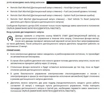
GETTING TO KNOW YOUR VEHICLE If an engine fault is present or fuel level is low, WARNING! WARNING! the vehicle will start and then shut down in 10 seconds. Do not start or run an engine in a closed Do not start or run an engine in a closed …
-
Page 28: Remote Start Front Defrost Activation — If Equipped
GETTING TO KNOW YOUR VEHICLE NOTE: NOTE: menu screen within Uconnect Settings Ú page 234. In warm weather, the driver vented These features will stay on through the duration of To avoid unintentional shutdowns, the system seat feature will automatically turn on when the Remote Start, or until the ignition is placed in the will disable for two seconds after receiving a Remote Start is activated and is programmed in…
-
Page 29: Remote Start — If Equipped (Diesel)
GETTING TO KNOW YOUR VEHICLE The message will stay active until the ignition is To drive the vehicle, push the unlock button, and WARNING! placed in the ON/RUN position. place the ignition in the ON/RUN position. Do not start or run an engine in a closed …
-
Page 30: To Arm The System
GETTING TO KNOW YOUR VEHICLE Cycle the ignition out of the OFF position to If the Vehicle Security system is armed and the YSTEM disarm the system. battery becomes disconnected, the Vehicle Follow these steps to arm the Vehicle Security Security system will remain armed when the NOTE: system:…
-
Page 31: Power Door Locks — If Equipped
GETTING TO KNOW YOUR VEHICLE — I knob is down when the door is closed, the door will OWER OCKS QUIPPED WARNING! lock. Therefore, make sure the key fob is not inside The power door lock switches are located on each the vehicle before closing the door.
-
Page 32: Power Side Steps — If Equipped
GETTING TO KNOW YOUR VEHICLE If the door lock switch is pushed while the ignition you to lock and unlock the vehicle’s door(s) without To Unlock From The Driver Or Passenger Side is in ACC or ON/RUN and the driver’s door is open, having to push the key fob lock or unlock buttons.
-
Page 33
GETTING TO KNOW YOUR VEHICLE Frequency Operated Button Integrated Key When any of these situations occur, after all open (FOBIK-Safe) doors are shut, the FOBIK-Safe search will be executed. If it detects a Passive Entry key fob To minimize the possibility of unintentionally inside the vehicle, the vehicle will unlock and alert locking a Passive Entry key fob inside your vehicle, the customer. -
Page 34: Automatic Unlock Doors On Exit
GETTING TO KNOW YOUR VEHICLE — NOTE: UTOMATIC NLOCK OORS HILD ROTECTION After pushing the door handle button, you must — R QUIPPED YSTEM OORS wait two seconds before you can lock or unlock The doors will unlock automatically on vehicles To provide a safer environment for small children the doors, using either Passive Entry door with power door locks after the following sequence…
-
Page 35: Steering Wheel
GETTING TO KNOW YOUR VEHICLE NOTE: NOTE: Always use this device when carrying children. When the Child-Protection Door Lock system is After engaging the Child-Protection Door Lock engaged, the door can be opened only by using system on both rear doors, check for effective the outside door handle even though the inside engagement by trying to open a door with the door lock is in the unlocked position.
-
Page 36: Heated Steering Wheel — If Equipped
GETTING TO KNOW YOUR VEHICLE — NOTE: EATED TEERING HEEL WARNING! Your vehicle is equipped with two key fobs, each QUIPPED can be linked to either memory position 1 or 2. Persons who are unable to feel pain to the …
-
Page 37: Programming The Memory Feature
GETTING TO KNOW YOUR VEHICLE NOTE: To recall the memory settings for driver one or two, ROGRAMMING EMORY EATURE Before programming your key fob you must select push the desired memory button number (1 or 2) To create a new memory profile, perform the or the unlock button on the key fob linked to the the “Personal Settings Linked to Key Fob”…
-
Page 38: Manual Adjustment (Front Seats)
GETTING TO KNOW YOUR VEHICLE ) — Manual Front Seat Recline Adjustment ANUAL DJUSTMENT RONT EATS The recline lever is located on the outboard side of QUIPPED the seat. To recline the seat, lean forward slightly, lift the lever, lean back to the desired position and WARNING! release the lever.
-
Page 39: Manual Adjustment (Rear Seats)
GETTING TO KNOW YOUR VEHICLE Front Bench Seat — If Equipped Reclining Rear Seats — If Equipped The seat is divided into three segments. The The recliner handle is located on the front of the outboard seat portions are each 40% of the total rear outboard seat cushions.
-
Page 40: Power Adjustment (Front Seats)
GETTING TO KNOW YOUR VEHICLE ) — Adjusting The Seat Forward Or Rearward OWER DJUSTMENT RONT EATS WARNING! The seat can be adjusted both forward and QUIPPED Adjusting a seat while driving may be rearward by using the power seat switch. The seat dangerous.
-
Page 41: Heated Seats — If Equipped
GETTING TO KNOW YOUR VEHICLE Power Lumbar — If Equipped Easy Entry/Exit Seat — If Equipped When enabled in Uconnect Settings, Easy Entry and Easy Exit positions are stored in each memory Vehicles equipped with power driver or passenger This feature provides automatic driver’s seat setting profile Ú…
-
Page 42: Ventilated Seats — If Equipped
GETTING TO KNOW YOUR VEHICLE — I Front Heated Seats — If Equipped Rear Heated Seats — If Equipped ENTILATED EATS QUIPPED The heated seat control buttons are On some models, the two rear outboard Front Ventilated Seats located on the center stack below the seats may be equipped with heated The ventilated seat control buttons are radio screen, or within the Uconnect…
-
Page 43: Plastic Grocery Bag Retainers
GETTING TO KNOW YOUR VEHICLE Rear Ventilated Seats — If Equipped Front Head Restraints ESTRAINTS If equipped, the two outboard rear seats Your vehicle is equipped with front four-way driver Head restraints are designed to reduce the risk of will have ventilated seats. The rear and passenger head restraints.
-
Page 44
GETTING TO KNOW YOUR VEHICLE NOTE: To adjust the head restraint forward, pull the top of the head restraint toward the front of the vehicle If your vehicle is equipped with a front bench seat, as desired and release. To adjust the head the center head restraint is not adjustable or restraint rearward, pull the top of the head removable. -
Page 45: Uconnect Voice Recognition
On Uconnect 5 systems, the factory default Wake Up” word and state your command. Some Up word is set to “Hey Uconnect” and can be repro- examples of “Wake Up” words include “Hey grammed through the Uconnect Settings. Uconnect” or “Hey Ram”. Uconnect 3 With 5-inch Display…
-
Page 46: Additional Information
GETTING TO KNOW YOUR VEHICLE 5. You can interrupt the help message or system DDITIONAL NFORMATION prompts by pushing the VR or Phone button © 2021 FCA US LLC. All rights reserved. Mopar and and saying a Voice Command from the current Uconnect are registered trademarks and Mopar category.
-
Page 47: Mirrors
GETTING TO KNOW YOUR VEHICLE MIRRORS For vehicles equipped with Driver Memory Automatic Dimming Mirror — If Equipped Settings Ú page 34, you can use your key fob or The rearview mirror can be adjusted up, down, left, the memory switch on the driver’s door trim NSIDE EARVIEW IRROR…
-
Page 48: Illuminated Vanity Mirror
GETTING TO KNOW YOUR VEHICLE Digital Rearview Mirror — If Equipped Push the menu button next to the on/off control/ LLUMINATED ANITY IRROR toggle to access the following mirror options: The Digital Rearview Mirror provides a high To access an illuminated vanity mirror, flip down Brightness definition, wide and unobstructed view of the road …
-
Page 49: Outside Mirrors
GETTING TO KNOW YOUR VEHICLE “Slide-On-Rod” Features Of Sun Visor — Outside Mirrors Folding Feature UTSIDE IRRORS If Equipped All outside mirrors are hinged and may be moved The outside mirror(s) can be adjusted to the center either forward or rearward to resist damage. The The sun visor “Slide-On-Rod”…
-
Page 50: Power Mirrors
GETTING TO KNOW YOUR VEHICLE If the mirror does not fold automatically, check for OWER IRRORS ice or dirt buildup at the pivot area, which can The power mirror switch is located on the driver’s cause excessive drag. side door trim panel. Power Mirror Movement Power mirror preselected positions can be controlled by the optional Driver Memory Settings…
-
Page 51: Trailer Towing Mirrors — If Equipped
GETTING TO KNOW YOUR VEHICLE To reset the power folding mirrors: Fold and unfold A small blindspot mirror is located next to the main The outside mirrors will then return to the original them by pushing the button (this may require mirror and can be adjusted manually.
-
Page 52: Before You Begin Programming
GETTING TO KNOW YOUR VEHICLE Use this QR code to access your programmed to the HomeLink® system. Make DENTIFYING HETHER digital experience. sure your hand-held transmitter is programmed to OLLING OLLING activate the device you are trying to program your HomeLink®…
-
Page 53: Programming Homelink® To A Garage Door Opener
GETTING TO KNOW YOUR VEHICLE ® T plugged in before moving on to the rolling code/ Non-Rolling Code Garage Door Opener Final Steps ROGRAMMING non-rolling code final steps. 1. Push and hold the programmed HomeLink® ARAGE PENER Rolling Code Garage Door Opener Final Steps button and observe the HomeLink®…
-
Page 54: Miscellaneous Device
GETTING TO KNOW YOUR VEHICLE ® T 1. Place the ignition in the ON/RUN position, It may be helpful to unplug the device during the ROGRAMMING without starting the engine. cycling process to prevent possible overheating of ISCELLANEOUS EVICE the garage door or gate motor. 2.
-
Page 55: Security
GETTING TO KNOW YOUR VEHICLE 5. Push and hold the programmed HomeLink® If you have any problems, or require assistance, ECURITY button and observe the indicator light. please call toll-free 1-800-355-3515 or, on the It is advised to erase all channels before you sell or Internet at HomeLink.com for information or…
-
Page 56: Exterior Lights
GETTING TO KNOW YOUR VEHICLE EXTERIOR LIGHTS NOTE: For vehicles sold in Canada, rotate the headlight switch clockwise from the parking lights and EADLIGHT WITCH instrument panel lights position to the first detent The headlight switch is located on the left side of to turn on headlights, parking lights, and the instrument panel.
-
Page 57: Multifunction Lever
GETTING TO KNOW YOUR VEHICLE On some vehicles, the Daytime Running Lights Broken, muddy, or obstructed headlights and ULTIFUNCTION EVER may deactivate, or reduce intensity, on one side taillights of vehicles in the field of view will The multifunction lever is located on the left side of of the vehicle (when a turn signal is activated on cause headlights to remain on longer (closer to the steering column.
-
Page 58: Automatic Headlights — If Equipped
GETTING TO KNOW YOUR VEHICLE — I UTOMATIC EADLIGHTS QUIPPED UTOMATIC EADLIGHTS IPERS EADLIGHT ELAY This system automatically turns the headlights on If your vehicle is equipped with Automatic To assist when exiting the vehicle, the headlight or off according to ambient light levels. To turn the Headlights, it also has this delay feature will leave the headlights on for up to system on, rotate the headlight switch to the AUTO…
-
Page 59: Fog Lights — If Equipped
GETTING TO KNOW YOUR VEHICLE — I — I The fog lights will operate only when the parking IGHTS QUIPPED HANGE SSIST QUIPPED lights are on or when the vehicle headlights are on To activate the front fog lights, turn on the parking Lightly push the multifunction lever up or down, low beam.
-
Page 60
GETTING TO KNOW YOUR VEHICLE When the vehicle is stationary, these lights can When these lights are activated using the button also be turned on using the switch located just on the headlight switch the cargo lights, trailer inside the pickup box, on the lower part of the bed spotter lights, and trailer hitch light will remain light lens. -
Page 61: Battery Saver
GETTING TO KNOW YOUR VEHICLE Front Map/Reading Lights ATTERY AVER The overhead console lights can also be operated Timers are set to both the interior and exterior individually as reading lights by pushing the lights to protect the life of your vehicle’s battery. corresponding buttons.
-
Page 62: Illuminated Entry
GETTING TO KNOW YOUR VEHICLE NOTE: LLUMINATED NTRY The courtesy/reading lights will remain on until the The courtesy lights will turn on when you use the switch is pushed a second time, so be sure they key fob to unlock the doors or open any door. have been turned off before exiting the vehicle.
-
Page 63: Windshield Wipers And Washers
GETTING TO KNOW YOUR VEHICLE WINDSHIELD WIPERS AND WASHERS The delay interval decreases as you rotate the WARNING! knob until it enters the low continual speed The windshield wiper/washer controls are located position. The delay can be regulated from a Sudden loss of visibility through the windshield on the multifunction lever on the left side of the maximum of about 18 seconds between cycles, to…
-
Page 64: Rain Sensing Wipers — If Equipped
GETTING TO KNOW YOUR VEHICLE — I The Rain Sensing system has protection features ENSING IPERS QUIPPED UTOMATIC LIMATE ONTROL for the wiper blades and arms, and will not operate ESCRIPTIONS UNCTIONS This feature senses rain or snowfall on the under the following conditions: windshield and automatically activates the wipers.
-
Page 65
GETTING TO KNOW YOUR VEHICLE NOTE: outside conditions, such as smoke, odors, dust, or You can turn AUTO on in one of two ways: Icons and descriptions can vary based upon high humidity are present. Recirculation can be Press and release this button on the touch- … -
Page 66
GETTING TO KNOW YOUR VEHICLE Rear Defrost Button Driver And Passenger Temperature Up And SYNC Button Down Buttons Press and release the Rear Defrost Press the SYNC button on the button on the touchscreen, or push and touchscreen to toggle the SYNC feature These buttons provide the driver and passenger release the button on the faceplate, to on/off. -
Page 67: Manual Climate Control Descriptions And Functions
GETTING TO KNOW YOUR VEHICLE Touchscreen NOTE: ANUAL LIMATE ONTROL Bi-Level mode is designed under comfort condi- Use the small blower icon to reduce the blower ESCRIPTIONS UNCTIONS tions to provide cooler air out of the panel outlets setting and the large blower icon to increase the and warmer air from the floor outlets.
-
Page 68
GETTING TO KNOW YOUR VEHICLE A/C Button fogging on the inside of the windshield. The A/C The rear window defroster automatically turns off can be deselected manually without disturbing the after 10 minutes. Push the A/C button to engage the Air mode control selection. -
Page 69: Automatic Temperature Control (Atc)
GETTING TO KNOW YOUR VEHICLE Blower Control Bi-Level Mode UTOMATIC EMPERATURE ONTROL (ATC) — I Blower Control regulates the amount of Air comes from the instrument panel QUIPPED air forced through the climate control outlets and floor outlets. A slight amount Automatic Operation system.
-
Page 70: If Equipped
GETTING TO KNOW YOUR VEHICLE Window Fogging To provide you with maximum comfort in the PERATING Automatic mode during cold start-ups, the blower Vehicle windows tend to fog on the inside in mild, Refer to the chart at the end of this section for fan will remain on low until the engine warms up.
-
Page 71: Interior Storage And Equipment
GETTING TO KNOW YOUR VEHICLE INTERIOR STORAGE AND EQUIPMENT Operating Tips Chart If equipped with a covered upper glove compartment, push the release button to open. WEATHER CONTROL SETTINGS TORAGE To open the lower glove compartment, pull the release handle. Set the mode control to Glove Compartment (Panel Mode),…
-
Page 72
GETTING TO KNOW YOUR VEHICLE Center Storage Compartment — WARNING! If Equipped In a collision, the latch may open if the total The center storage compartment is located weight of the items stored exceeds about between the driver and passenger seats. The 10 lb (4.5 kg). -
Page 73
GETTING TO KNOW YOUR VEHICLE Premium Center Console — If Equipped The premium center console is equipped with two front storage bins located in front of the center storage compartment. These storage bins may be equipped with tandem doors. Push the front bin to access the cupholders. -
Page 74
GETTING TO KNOW YOUR VEHICLE Overhead Sunglass Storage Push the release button at the front of the cupholder bin to slide tray rearward to access the At the front of the overhead console, a front lower storage bin, or forward to access the compartment is provided for the storage of one rear lower storage bin. -
Page 75
GETTING TO KNOW YOUR VEHICLE There is a storage drawer located in the lower Second Row In-Floor Storage Bin — center of the instrument panel (if equipped). It can If Equipped be released by pushing the access button above it. In-floor storage bins are located in front of the Pull drawer outward to the fully open position. -
Page 76
GETTING TO KNOW YOUR VEHICLE NOTE: NOTE: Flip the inside of the base upward into the upright position, locking into place, creating and extended The front seat may have to be moved forward to The maximum load limit for each hook is 250 lb storage area. -
Page 77: Usb/Aux Control
GETTING TO KNOW YOUR VEHICLE USB/AUX C A third and fourth USB ports are located behind the ONTROL center console, above the power inverter. Both are Located on the center stack, just below the charge only. instrument panel, is the main media hub. There Applicable to only Uconnect 5/5 NAV With 8.4-inch are four total USB ports: Two Mini-USBs (Type C) Display, and Uconnect 5 NAV With 12-inch Display…
-
Page 78: Electrical Power Outlets
GETTING TO KNOW YOUR VEHICLE If equipped, two Mini-USB ports (Type C), two For further information, refer to the Uconnect CAUTION! Standard USB ports (Type A), and one AUX port Owner’s Manual Supplement or visit may be located to the left of the center stack, just UconnectPhone.com Power outlets are designed for accessory …
-
Page 79: Power Inverter — If Equipped
GETTING TO KNOW YOUR VEHICLE The auxiliary power outlet can be changed to battery WARNING! CAUTION! powered at all times by switching the power outlet fuses in the Internal Power Distribution Center To avoid serious injury or death: After the use of high power draw accessories, …
-
Page 80
GETTING TO KNOW YOUR VEHICLE NOTE: There is also a second 115 Volt (400 Watts If equipped with a front bench seat, there may be Maximum) power inverter located on the rear of a 115 Volt (400 Watts Maximum) inverter located The Center Stack Power Inverter is only avail- … -
Page 81: Wireless Charging Pad — If Equipped
GETTING TO KNOW YOUR VEHICLE WINDOWS — The wireless charging pad is equipped with an IRELESS HARGING anti-slip mat, a cradle to hold your mobile phone in QUIPPED place, and an LED indicator light. OWER INDOWS LED Indicator Status: The window controls on the driver’s door control all NOTE: the door windows.
-
Page 82: Automatic Window Features
GETTING TO KNOW YOUR VEHICLE NOTE: To stop the window from going all the way down WARNING! during the Auto-Down operation, pull up or push The power window switches will remain active for down on the switch briefly. up to 10 minutes after the ignition is placed in the There is no anti-pinch protection when the OFF position.
-
Page 83: Window Lockout Switch
GETTING TO KNOW YOUR VEHICLE — — INDOW OCKOUT WITCH OWER LIDING INDOW ANUAL LIDING INDOW QUIPPED QUIPPED The window lockout switch on the driver’s door trim panel allows you to disable the window controls on The switch for the power sliding rear window is A locking device in the center of the window helps the rear passenger doors.
-
Page 84: Power Sunroof — If Equipped
GETTING TO KNOW YOUR VEHICLE POWER SUNROOF — IF EQUIPPED Opening And Closing The Sunroof WARNING! Express Open/Close — Never leave children unattended in a vehicle, INGLE OWER UNROOF Push the switch rearward and release it within or with access to an unlocked vehicle. Never QUIPPED one-half second and the sunroof will open leave the key fob in or near the vehicle, or in a…
-
Page 85: Dual Pane Power Sunroof — If Equipped
GETTING TO KNOW YOUR VEHICLE Any release of the switch during open or close Venting Sunroof Sunroof Maintenance operation will stop the sunroof movement. The Push and release the Vent button within one half Use only a non-abrasive cleaner and a soft cloth to sunroof will remain in a partially opened position second and the sunroof will open to the vent clean the glass panel.
-
Page 86
GETTING TO KNOW YOUR VEHICLE Opening And Closing The Power Sunshade Express Open/Close WARNING! Push the switch rearward and release it within The sunshade has two programmed positions: half Never leave children unattended in a vehicle, one-half second and the sunroof will open open and full open positions. -
Page 87: Hood
GETTING TO KNOW YOUR VEHICLE HOOD Manual Open/Close Venting Sunroof Push and hold the sunshade switch rearward, the Push and release the Vent button within one half sunshade will open to the half open position and second and the sunroof will open to the vent stop automatically.
-
Page 88: To Close The Hood
GETTING TO KNOW YOUR VEHICLE 2. Reach into the opening beneath the center of If equipped, a button on the center overhead CAUTION! the hood and push the safety latch lever to the console inside the vehicle can be used to release left to release it, before raising the hood.
-
Page 89: Multifunction Tailgate — If Equipped
GETTING TO KNOW YOUR VEHICLE — ULTIFUNCTION AILGATE WARNING! QUIPPED To prevent serious injury or death: The 60/40 multifunction tailgate has two swing Always keep hands away from the hinge sides doors to allow for closer access to the pickup box of the swing doors and where the doors meet with the doors open.
-
Page 90: Tailgate Removal
GETTING TO KNOW YOUR VEHICLE NOTE: AILGATE EMOVAL Rest the tailgate on the bumper so that the entire NOTE: tailgate is secure and supported. Removing the tailgate will disable the rearview camera function. WARNING! To remove the tailgate, follow the instructions For vehicles equipped with a multifunction below: tailgate, the tailgate weighs 115 lb (52 kg) and…
-
Page 91
GETTING TO KNOW YOUR VEHICLE 8. Connect the tailgate plugs (provided in the glove compartment) to the tailgate wiring harness to ensure that the terminals do not corrode. Locking Tab Disconnected Body Side Harness 6. Disconnect the wiring harness by pushing on 7. -
Page 92: Bed Step — If Equipped
GETTING TO KNOW YOUR VEHICLE NOTE: 10. Raise the tailgate slightly, and remove the If your vehicle is equipped with a standard tailgate, support cables by releasing the lock tang from the step will be located on the driver’s side of the Do not carry the tailgate loose in the truck …
-
Page 93
GETTING TO KNOW YOUR VEHICLE that will avoid coming into contact with the step as release the spring load and extend the bed step it extends. out and away from the tailgate. To stow the bed step back under the tailgate, push the bed step forward with your foot until the bed step is retracted by the spring load. -
Page 94: Pickup Box
GETTING TO KNOW YOUR VEHICLE PICKUP BOX You can carry wide building materials (sheets of WARNING! plywood, etc.) by building a raised load floor. Place The pickup box has many features designed for lumber across the box in the indentations provided If you wish to carry more than 600 lb (272 kg) …
-
Page 95: Bed Rail Tie-Down System — If Equipped
GETTING TO KNOW YOUR VEHICLE — To move the cleat to any position on the rail, turn YSTEM the nut counterclockwise, approximately three QUIPPED turns. Then pull out on the cleat and slide it to the detent nearest the desired location. Make sure the CAUTION! cleat is seated in the detent and tighten the nut.
-
Page 96: Rambox — If Equipped
GETTING TO KNOW YOUR VEHICLE RAMBOX — IF EQUIPPED Cleat Removal (Without Tonneau Cover) CAUTION! Remove the end cap by pushing upward on the The RamBox system is an integrated pickup box Damage to the RamBox bin may occur due to release button located beneath the end cap while …
-
Page 97
GETTING TO KNOW YOUR VEHICLE The interior of the RamBox will automatically CAUTION! illuminate when the lid is opened. The timing can be adjusted within Uconnect Settings Ú page 234. Failure to follow the following items could cause damage to the vehicle: Cargo bins feature two removable drain plugs (to allow water to drain from bins). -
Page 98: Rambox Safety Warning
GETTING TO KNOW YOUR VEHICLE If equipped, a 115 Volt (400 Watts Maximum) WARNING! inverter may be located inside the RamBox of your vehicle. The inverter can be turned on by the Do not drive the vehicle with the storage bin …
-
Page 99: Bed Divider — If Equipped
GETTING TO KNOW YOUR VEHICLE — I IVIDER QUIPPED The bed divider has two functional positions: Divider Position Storage Position Divider Position The divider position is intended for managing your cargo and assisting in keeping cargo from moving around the bed.
-
Page 100: Tri-Fold Tonneau Cover — If Equipped
GETTING TO KNOW YOUR VEHICLE 5. Lock the center handle to secure the panel ONNEAU OVER OMPONENTS into place. Storage Position The storage position for the bed divider is at the front of the truck bed which maximizes the bed cargo area when not in use.
-
Page 101: Tri-Fold Tonneau Cover Folding For Driving Or Removal
GETTING TO KNOW YOUR VEHICLE ONNEAU OVER OLDING RIVING EMOVAL To remove the Tonneau Cover use the following steps: 1. Open the tailgate to access the rear pair of Tonneau Cover latches located on the underside of the Cover. Tonneau Cover Latch Components Position One (Front Latches Latched And Stowage Straps Secured) 1 —…
-
Page 102
GETTING TO KNOW YOUR VEHICLE 3. Holding the bumper, push the fully released latch to the center and push up. Push the handle firmly, locking it into the stowed position. Repeat Steps 2 and 3 for the opposite side latch. Slide Locking Lever Inward Released Position 2. -
Page 103
GETTING TO KNOW YOUR VEHICLE 4. Lift up on Panel 3 and fold it onto Panel 2. 5. Lift up on the second and third panel and fold NOTE: them onto the first panel. Be sure the Tonneau Cover has been folded completely, and the stowage straps are engaged, before removing. -
Page 104: Tri-Fold Tonneau Cover Installation
GETTING TO KNOW YOUR VEHICLE NOTE: ONNEAU OVER The vehicle can be driven with the Tonneau in the NSTALLATION folded position or can be completely removed. To install the Tonneau Cover follow these steps: 1. Position the Tonneau Cover on the truck bed and center using the locating bumpers.
-
Page 105
GETTING TO KNOW YOUR VEHICLE Slide Locking Lever Towards Inside Of Truck Released Position J Hook Under Truck Flange 3. Swing the J Hook from the handle and push 1 — Front Of Truck the handle to the center and up, ensuring that 2 —… -
Page 106
GETTING TO KNOW YOUR VEHICLE NOTE: 6. Unfold the Tonneau Cover to the second panel position. When folding the second and third panels, the sections MUST be held together to avoid damage to the cover material. Fold the panel gently. Do not allow the panels to drop under their own weight. -
Page 107: Tri-Fold Tonneau Cover Cleaning
GETTING TO KNOW YOUR VEHICLE 7. Completely unfold the Tonneau Cover. 9. Pull down on the handle to ensure the Slide 10. Gently pull up on all four corners of the Locking Lever is fully engaged. Do this for both Tonneau Cover to ensure that it is properly CAUTION! the left and right side.
-
Page 108: Getting To Know Your Instrument Panel
GETTING TO KNOW YOUR INSTRUMENT PANEL BASE / MIDLINE INSTRUMENT CLUSTER — GASOLINE…
-
Page 109: Base / Midline Instrument Cluster
GETTING TO KNOW YOUR INSTRUMENT PANEL 4. Oil Pressure Gauge IDLINE NSTRUMENT LUSTER WARNING! — G The pointer should always indicate the oil ESCRIPTIONS ASOLINE A hot engine cooling system is dangerous. You or pressure when the engine is running. A 1.
-
Page 110: Premium Instrument Cluster — Gasoline
GETTING TO KNOW YOUR INSTRUMENT PANEL PREMIUM INSTRUMENT CLUSTER — GASOLINE…
-
Page 111: Premium Instrument Cluster Descriptions — Gasoline
GETTING TO KNOW YOUR INSTRUMENT PANEL 4. Temperature Gauge REMIUM NSTRUMENT LUSTER CAUTION! — G The pointer shows engine coolant tempera- ESCRIPTIONS ASOLINE Driving with a hot engine cooling system could ture. The pointer positioned within the 1. Tachometer damage your vehicle.
-
Page 112: Base / Midline Instrument Cluster — Diesel
GETTING TO KNOW YOUR INSTRUMENT PANEL BASE / MIDLINE INSTRUMENT CLUSTER — DIESEL…
-
Page 113: Base / Midline Instrument Cluster
GETTING TO KNOW YOUR INSTRUMENT PANEL 3. Instrument Cluster Display IDLINE NSTRUMENT LUSTER WARNING! — D When the appropriate conditions exist, this ESCRIPTIONS IESEL A hot engine cooling system is dangerous. You or display shows the instrument cluster 1. Tachometer others could be badly burned by steam or boiling display messages Ú…
-
Page 114
GETTING TO KNOW YOUR INSTRUMENT PANEL • The DEF gauge may also not immediately 6. Diesel Exhaust Fluid (DEF) Gauge 7. Fuel Gauge update after a refill if the temperature of The DEF Gauge displays the actual level of The gauge shows the level of fuel in the fuel … -
Page 115: Premium Instrument Cluster — Diesel
GETTING TO KNOW YOUR INSTRUMENT PANEL PREMIUM INSTRUMENT CLUSTER — DIESEL…
-
Page 116: Descriptions — Diesel
GETTING TO KNOW YOUR INSTRUMENT PANEL completely full. To put it another way, 5. Fuel Gauge REMIUM NSTRUMENT LUSTER there’s additional storage capacity in the — D The pointer shows the level of fuel in the ESCRIPTIONS IESEL tank above the Full mark that’s not repre- fuel tank when the ignition switch is in the 1.
-
Page 117: Instrument Cluster Display Location And
GETTING TO KNOW YOUR INSTRUMENT PANEL NOTE: NSTRUMENT LUSTER ISPLAY OCATION AND ONTROLS Holding the up / down or left / right arrow buttons will loop the user through the The instrument cluster display features a driver currently selected menu or options presented interactive display that is located in the instrument on the screen.
-
Page 118: Oil Life Reset
GETTING TO KNOW YOUR INSTRUMENT PANEL 4. Push and hold the OK button to reset oil life. If Vehicle Info ESET conditions are met, the gauge and numeric Push and release the up or down arrow Your vehicle is equipped with an engine oil change display will update to show 100%.
-
Page 119
GETTING TO KNOW YOUR INSTRUMENT PANEL Off Road – If Equipped NOTE: Adaptive Cruise Control Ready When vehicle speed becomes too high to display When ACC is activated but the vehicle speed Push and release the up or down arrow the pitch and roll, “- -”… -
Page 120
GETTING TO KNOW YOUR INSTRUMENT PANEL Performance Features — If Equipped Push and release the up or down arrow button until the Performance icon/title is highlighted in the instrument cluster display. Push and release the left or right arrow button to scroll through the performance feature submenus. WARNING! Measurement of vehicle statistics with the Performance Features is intended for off-highway or track use only and should not be done on any public roadways. -
Page 121
GETTING TO KNOW YOUR INSTRUMENT PANEL 0-60 feet (0-20 meters)/Reaction Timer Best Last Current NOTE: Reaction Time result is shown only on the 60 ft timer tab. 0-330 feet (0-100 meters) Timer Best Last Current … -
Page 122
GETTING TO KNOW YOUR INSTRUMENT PANEL Distance Braking Distance From Speed Current G-Forces Peak Lap Timer Shows times for Last, Best, and Current laps ran. Lap History Will list the last four laps with the best lap highlighted in green. … -
Page 123
GETTING TO KNOW YOUR INSTRUMENT PANEL Trailer Tow — If Equipped Audio Settings Head-Up Display (HUD) – If Equipped Push and release the up or down arrow Push and release the up or down arrow button until the Trailer Tow menu item is button until the Audio Menu icon/title is NOTE: highlighted in the instrument cluster display. -
Page 124: Head-Up Display (Hud) — If Equipped
GETTING TO KNOW YOUR INSTRUMENT PANEL Odometer Upper Left or Right Left Side and Right Side – If Equipped No Decimal Point None Time Current Econ Range To None Average Econ Decimal Point Empty Compass Range Trip A Distance Defaults (Restores All Settings To Default Settings) Transmission Outside Temp…
-
Page 125
GETTING TO KNOW YOUR INSTRUMENT PANEL Content and Layout When “Standard” mode is selected, the HUD When “Advanced” mode is selected, the HUD image is split into thirds with the speed limit displays the vehicle speed, turn-by-turn naviga- When “Display On” is selected, the HUD will indicator shown to the left, vehicle speed in the tion, speed limit, driver assist function(s), and display on the windshield. -
Page 126: Diesel Particulate Filter (Dpf) Messages
GETTING TO KNOW YOUR INSTRUMENT PANEL Display Height tion in the particulate filter system and allow WARNING! your diesel engine and exhaust after-treatment Brightness system to cleanse the filter to remove the A hot exhaust system can start a fire if you park NOTE: trapped PM and restore the system to normal over materials that can burn, such as grass or…
-
Page 127: Displays
GETTING TO KNOW YOUR INSTRUMENT PANEL (DEF) Exhaust Filter Full — Power Reduced See ISPLAYS IESEL XHAUST LUID Dealer — This message indicates the PCM has ARNING ESSAGES When the appropriate conditions exist, the derated the engine to limit the likelihood of instrument cluster display displays the following permanent damage to the after-treatment Your vehicle will begin displaying warning…
-
Page 128: Diesel Exhaust Fluid (Def) Fault Warning Messages
GETTING TO KNOW YOUR INSTRUMENT PANEL while operating the vehicle. Chimes will also and have your vehicle serviced immediately. If Engine Will Not Restart Service DEF System See accompany the 75, 50 and 25 mile remaining not corrected in 50 miles, vehicle will enter the Dealer —…
-
Page 129: Battery Saver On/Battery Saver Mode Message — Electrical Load Reduction Actions — If Equipped
GETTING TO KNOW YOUR INSTRUMENT PANEL These messages indicate the vehicle battery has a Turning on all possible vehicle electrical loads ATTERY AVER ATTERY AVER low state of charge and continues to lose electrical (e.g. HVAC to max settings, exterior and interior —…
-
Page 130: Warning Lights And Messages
GETTING TO KNOW YOUR INSTRUMENT PANEL WARNING LIGHTS AND MESSAGES Brake Warning Light What to do when an electrical load reduction action message is present (“Battery Saver On” or This warning light monitors various brake The warning/indicator lights will illuminate in the “Battery Saver Mode”) functions, including brake fluid level and instrument panel together with a dedicated…
-
Page 131
GETTING TO KNOW YOUR INSTRUMENT PANEL NOTE: The light also will turn on when the parking brake Electronic Throttle Control (ETC) Warning is applied with the ignition switch in the ON/RUN The light may flash momentarily during sharp Light position. cornering maneuvers, which change fluid level This warning light will illuminate to conditions. -
Page 132
GETTING TO KNOW YOUR INSTRUMENT PANEL Electric Power Steering (EPS) Fault Hood Open Warning Light Oil Temperature Warning Light Warning Light This warning light will illuminate when the This warning light will illuminate to hood is ajar/open and not fully closed. indicate the engine oil temperature is This warning light will turn on when high. -
Page 133: Yellow Warning Lights
GETTING TO KNOW YOUR INSTRUMENT PANEL Trailer Brake Disconnected Warning Light Vehicle Security Warning Light — If the ABS light remains on or turns on while driving, then the Anti-Lock portion of the brake If Equipped This warning light will illuminate when the system is not functioning and service is required as Trailer Brake has been disconnected.
-
Page 134
GETTING TO KNOW YOUR INSTRUMENT PANEL Low Washer Fluid Warning Light — several miles (kilometers) at speeds greater than the light stays on through several typical driving 30 mph (48 km/h), see an authorized dealer as styles. In most situations, the vehicle will drive If Equipped soon as possible to have the problem diagnosed normally and will not require towing. -
Page 135
GETTING TO KNOW YOUR INSTRUMENT PANEL Rear Axle Locker Fault Indicator Light — Cruise Control Fault Warning Light Each tire, including the spare (if provided), should be checked monthly when cold and inflated to the If Equipped This warning light will illuminate to inflation pressure recommended by the vehicle indicate the Cruise Control System is not This warning light will illuminate to… -
Page 136: Yellow Indicator Lights
GETTING TO KNOW YOUR INSTRUMENT PANEL Air Suspension Off-Road 1 Indicator Light — Your vehicle has also been equipped with a TPMS CAUTION! malfunction indicator to indicate when the system If Equipped is not operating properly. The TPMS malfunction The TPMS has been optimized for the original This light will illuminate when the air indicator is combined with the low tire pressure equipment tires and wheels.
-
Page 137
GETTING TO KNOW YOUR INSTRUMENT PANEL Air Suspension Ride Height Lowering Rear Axle Lock Indicator Light 4WD Low Indicator Light — If Equipped Indicator Light— If Equipped This light indicates when the rear axle This light alerts the driver that the vehicle lock has been activated. -
Page 138: Green Indicator Lights
GETTING TO KNOW YOUR INSTRUMENT PANEL Water In Fuel Indicator Light — If Equipped LaneSense Indicator Light — REEN NDICATOR IGHTS If Equipped The Water In Fuel Indicator Light will Adaptive Cruise Control (ACC) Set With illuminate when there is water detected The LaneSense indicator light illuminates Target Light —…
-
Page 139: White Indicator Lights
GETTING TO KNOW YOUR INSTRUMENT PANEL Turn Signal Indicator Lights LaneSense Indicator Light — If Equipped HITE NDICATOR IGHTS When the left or right turn signal is When the LaneSense system is ON, but Adaptive Cruise Control (ACC) Ready Light — activated, the turn signal indicator will not armed, the LaneSense indicator light If Equipped…
-
Page 140: Onboard Diagnostic System — Obd Ii
GETTING TO KNOW YOUR INSTRUMENT PANEL ONBOARD DIAGNOSTIC SYSTEM — OBD II CAUTION! WARNING! Your vehicle is equipped with a sophisticated Prolonged driving with the MIL on could cause ONLY an authorized service technician should Onboard Diagnostic system called OBD II. This further damage to the emission control connect equipment to the OBD II connection system monitors the performance of the…
-
Page 141: Emissions Inspection And Maintenance Programs
GETTING TO KNOW YOUR INSTRUMENT PANEL EMISSIONS INSPECTION AND Your vehicle has a simple ignition actuated test, The MIL will not flash at all and will remain which you can use prior to going to the test station. fully illuminated until you place the ignition MAINTENANCE PROGRAMS To check if your vehicle’s OBD II system is ready, in the off position or start the engine.
-
Page 142: Starting And Operating
STARTING AND OPERATING STARTING THE ENGINE WARNING! WARNING! GASOLINE ENGINE Before exiting a vehicle, always come to a Do not leave the key fob in or near the vehicle, complete stop, then shift the automatic trans- or in a location accessible to children, and do Before starting your vehicle, adjust your seat, mission into PARK and apply the parking brake.
-
Page 143: Automatic Transmission
STARTING AND OPERATING NOTE: To Turn Off The Engine Using The ENGINE START/ TART EATURE Engine start-up in very low ambient temperature STOP Button Do not press the accelerator. Cycle the ignition could result in evident white smoke. This condition 1.
-
Page 144: Autopark
STARTING AND OPERATING NOTE: ENGINE START/STOP Button Functions — With WARNING! Driver’s Foot OFF The Brake Pedal (In PARK Or For Keyless Enter ‘n Go™ equipped vehicles, the NEUTRAL Position) engine will turn off and the ignition switch will Driver inattention could lead to failure to place …
-
Page 145: If Engine Fails To Start
STARTING AND OPERATING If the driver shifts into PARK while moving, the The message “AutoPark Not Engaged” will be WARNING! vehicle may AutoPark. displayed in the instrument cluster. A warning chime will continue until you shift the vehicle into Do not attempt to push or tow your vehicle to …
-
Page 146: Normal Starting Using Engine Start/Stop Button — Diesel Engine
STARTING AND OPERATING If the engine shows no sign of starting after a 2. If the gear selector is not in PARK, the ENGINE CAUTION! 10 second period of engine cranking with the START/STOP button must be held for two accelerator pedal held to the floor, wait 10 to seconds or three short pushes in a row with If the Water in Fuel Indicator Light remains on,…
-
Page 147: Cold Weather Operation (Below -22°F Or −30°C)
STARTING AND OPERATING ENGINE START/STOP Button Functions — With FTER TARTING WARNING! Driver’s Foot OFF The Brake Pedal (In PARK Or The idle speed is controlled automatically, and it NEUTRAL Position) Never leave children alone in a vehicle, or with …
-
Page 148: Normal Operation — Diesel Engine
STARTING AND OPERATING NORMAL OPERATION — DIESEL ENGINE NOTE: EATHER RECAUTIONS Use of Climatized ULSD Fuel or Number 1 ULSD Operation in ambient temperature below 32°F Observe the following when the diesel engine is Fuel results in a noticeable decrease in fuel (0°C) may require special considerations.
-
Page 149: Engine Idling
STARTING AND OPERATING Winter Front Cover Engine Warm-Up NGINE DLING Avoid full throttle operation when the engine is Avoid prolonged idling. Long periods of idling may cold. When starting a cold engine, bring the engine be harmful to your engine because combustion up to operating speed slowly to allow the oil chamber temperatures can drop so low that the pressure to stabilize as the engine warms up.
-
Page 150: Stopping The Engine
STARTING AND OPERATING TOPPING NGINE After full load operation, idle the engine for a few minutes before shutting it down. This idle period will allow the lubricating oil and coolant to carry excess heat away from the turbocharger. Refer to the following chart for proper engine shutdown. Idle Time (min.) Driving Condition Load…
-
Page 151: Engine Block Heater — If Equipped
STARTING AND OPERATING Do Not Operate The Engine With Low Oil Do Not Operate The Engine With Failed The engine block heater warms engine coolant and permits quicker starts in cold weather. Connect the Pressure Parts heater cord to a ground-fault interrupter protected If the Low Oil Pressure Warning Light turns on while All engine failures give some warning before the 110–115 Volt AC electrical outlet with a grounded,…
-
Page 152: Engine Break-In Recommendations
STARTING AND OPERATING ENGINE BREAK-IN RECOMMENDATIONS — NOTE: The engine oil installed in the engine at the factory is a high-quality energy conserving type lubricant. A new engine may consume some oil during its first GASOLINE ENGINE Oil changes should be consistent with anticipated few thousand miles (kilometers) of operation.
-
Page 153
STARTING AND OPERATING The parking brake switch is located on the NOTE: NOTE: instrument panel to the left of the steering wheel The EPB fault light will illuminate if the EPB switch When parking on a hill, it is important to turn the (below the headlamp switch). -
Page 154
STARTING AND OPERATING Auto Park Brake If exceptional circumstances should make it WARNING! necessary to engage the parking brake while the The Electric Park Brake (EPB) can be programmed vehicle is in motion, maintain upward pressure on Do not leave the key fob in or near the vehicle, … -
Page 155: Automatic Transmission
STARTING AND OPERATING SafeHold can be temporarily bypassed by pushing While in Service Mode, the EPB fault lamp will flash WARNING! the EPB switch while the driver door is open. Once continuously while the ignition is in ON/RUN. manually bypassed, SafeHold will be enabled Your vehicle could move and injure you and …
-
Page 156: Ignition Park Interlock
STARTING AND OPERATING RAKE RANSMISSION HIFT WARNING! CAUTION! (BTSI) S NTERLOCK YSTEM Shift into or out of PARK or REVERSE only after Unintended movement of a vehicle could the vehicle has come to a complete stop. injure those in or near the vehicle. As with all This vehicle is equipped with a BTSI system that vehicles, you should never exit a vehicle while holds the transmission gear selector in PARK…
-
Page 157
STARTING AND OPERATING NOTE: In the event of a mismatch between the gear In the event of a mismatch between the gear selector position and the actual transmission gear (for example, driver selects PARK while selector position and the actual transmission gear driving), the position indicator will blink continu- (for example, driver selects PARK while driving), ously until the selector is returned to the proper… -
Page 158
STARTING AND OPERATING PARK (P) WARNING! This range supplements the parking brake by Your vehicle could move and injure you and locking the transmission. The engine can be others if it is not in PARK. Check by trying to started in this range. -
Page 159
STARTING AND OPERATING REVERSE (R) WARNING! WARNING! This range is for moving the vehicle backward. Unintended movement of a vehicle could Do not leave the key fob in or near the vehicle Shift into REVERSE only after the vehicle has come injure those in or near the vehicle. -
Page 160
STARTING AND OPERATING NOTE: DRIVE (D) Vehicle performance may be severely degraded and the engine may stall. In some situations, the Even if the transmission can be reset, we This range should be used for most city and transmission may not re-engage if the engine is recommend that you visit an authorized dealer at highway driving. -
Page 161
STARTING AND OPERATING maximize engine braking, eliminate undesirable AutoStick mode will downshift the transmission to the next lower gear, while tapping “+” to enter upshifts and downshifts, and improve overall vehicle performance. This feature can also provide AutoStick mode will retain the current gear. The you with more control during passing, city driving, current transmission gear will be displayed in the cold slippery conditions, mountain driving, trailer… -
Page 162: Four-Wheel Drive Operation — If Equipped
STARTING AND OPERATING FOUR-WHEEL DRIVE OPERATION — Transmission shifting will be more noticeable when AutoStick is enabled. IF EQUIPPED The system may revert to automatic shift mode if a fault or overheat condition is detected. OSITION LECTRONICALLY NOTE: —…
-
Page 163
STARTING AND OPERATING This electronically shifted transfer case provides The transfer case N (Neutral) button is located WARNING! four positions: in the center of the 4WD Control Switch and is pushed by using a ballpoint pen or similar You or others could be injured or killed if you … -
Page 164: Five-Position Electronically Shifted Transfer Case — If Equipped
STARTING AND OPERATING 3. If the transfer case will not shift, a message the 2WD or 4WD HIGH positions at a given road OSITION LECTRONICALLY will appear on the cluster stating the 4WD shift speed. Take care not to overspeed the engine and —…
-
Page 165
STARTING AND OPERATING Four-Wheel Drive Low Range (4WD LOW) — This WARNING! range provides low speed four-wheel drive. It maximizes torque (increased torque over 4WD The transmission may not engage PARK if the HIGH) to the front driveshaft; allowing front and vehicle is moving. -
Page 166
STARTING AND OPERATING NOTE: Transfer Case Position Indicator Lights Proper operation of four-wheel drive vehicles depends on tires of equal size, type and Before retrying a selection, make certain that all The Transfer Case Position Indicator Lights (4WD circumference on each wheel. Any difference in the necessary requirements for selecting a new HIGH, 4WD LOW, and 4WD AUTO) are located in tire size can cause damage to the drivetrain. -
Page 167: Active-Level Four Corner Air
STARTING AND OPERATING ACTIVE-LEVEL FOUR CORNER AIR not be available due to vehicle payload, an instrument cluster message will be displayed SUSPENSION SYSTEM — IF EQUIPPED when this occurs Ú page 114. CAUTION! ESCRIPTION If the vehicle is in Off-Road 1 or Off-Road 2 The air suspension system provides full-time setting, be aware of your surroundings, you may load-leveling capability along with the benefit of…
-
Page 168
STARTING AND OPERATING NOTE: Aero Height (Lowers the vehicle approximately CAUTION! 0.6 inch [15 mm]) – This position provides Automatic Aero Mode may be disabled through improved aerodynamics by lowering the vehicle. vehicle settings in the instrument cluster display When in ENTRY/EXIT Height, be aware of your The vehicle will automatically enter Automatic Ú… -
Page 169: Air Suspension Modes
STARTING AND OPERATING NOTE: Wheel Alignment Mode USPENSION ODES Default Ride Height: Before performing a wheel alignment, this mode The air suspension system has multiple modes to Select Aero Height or Normal Ride Height as the must be enabled which will put the vehicle into …
-
Page 170: Operation
STARTING AND OPERATING Pushing the height selector up once will move the Normal Ride Height (NRH) – Indicator lamps 5, PERATION suspension one position higher from the current 4 and 3 will be illuminated. position, assuming all conditions are met (i.e., Aero Height–…
-
Page 171: Active-Level Four Corner Air Suspension System (Off-Road Group) — If Equipped
STARTING AND OPERATING ACTIVE-LEVEL FOUR CORNER AIR will be automatically lowered to NRH. Off-Road may not be available due to vehicle payload, an SUSPENSION SYSTEM (OFF-ROAD GROUP) — instrument cluster display message will be shown when this occurs Ú page 114. IF EQUIPPED CAUTION! ESCRIPTION…
-
Page 172
STARTING AND OPERATING NOTE: To assist with changing a spare tire, the air to Normal Height Mode, push the height selector switch up twice while in Entry/Exit or suspension system has a feature which allows the Automatic Aero mode will be disabled if a … -
Page 173: Air Suspension Modes
STARTING AND OPERATING Load leveling will automatically resume as soon as The indicator lamps 1 through 4 will illuminate to USPENSION ODES system operation requirements are met. See an show the current position of the vehicle. Flashing The air suspension system has multiple modes to authorized dealer if system does not resume.
-
Page 174: Axle Lock System — If Equipped
STARTING AND OPERATING Automatic height changes will occur based on Wheel Alignment Mode – Indicator lamps 2, 3, CAUTION! vehicle speed and the current vehicle height. The and 4 will be illuminated. Wheel Alignment indicator lamps and instrument cluster display Mode is disabled by driving the vehicle or Do not lock the rear axle on hard surfaced …
-
Page 175: Limited-Slip Differential
STARTING AND OPERATING POWER STEERING Operating the locker in 2WD, 4WD AUTO, and and cornering, the limited-slip unit performs 4WD LOCK/HIGH, the locker can be engaged up to similarly to a conventional differential. On slippery 20 mph (32 km/h). While driving with the locker surfaces, however, the differential delivers more of LECTRIC OWER…
-
Page 176: Fuel Saver Technology 5.7L Engines
STARTING AND OPERATING NOTE: Releasing the brake pedal or shifting out of DRIVE The engine will shut down, the tachometer will will automatically restart the engine. move to the zero position and the stop/start Even if the power steering assistance is no …
-
Page 177: To Start The Engine While In Autostop Mode
STARTING AND OPERATING The transmission is not in DRIVE 12 Volt demand requires engine restart ANUALLY Hood is open Stop/Start OFF switch is pushed TART YSTEM Transfer case is in 4WD LOW Transfer case is in 4WD LOW …
-
Page 178: System Malfunction
STARTING AND OPERATING YSTEM ALFUNCTION RUISE ONTROL WARNING! If there is a malfunction in the Stop/Start system, When engaged, the Cruise Control takes over Cruise Control can be dangerous where the the system will not shut down the engine. A accelerator operations at speeds greater than system cannot maintain a constant speed.
-
Page 179
STARTING AND OPERATING To Set A Desired Speed Metric Speed (km/h) WARNING! Pushing the SET (+), or SET (-) button once will Turn the Cruise Control on. Cruise Control can be dangerous where the result in a 1 km/h speed adjustment. Each When the vehicle has reached the desired speed, system cannot maintain a constant speed. -
Page 180: Adaptive Cruise Control (Acc)
STARTING AND OPERATING Pushing the on/off button or placing the ignition in Fixed Speed Cruise Control (ACC not enabled) WARNING! the OFF position, erases the set speed from will not detect vehicles directly ahead of you. memory. Always be aware of the feature selected Does not always fully recognize complex …
-
Page 181
STARTING AND OPERATING Adaptive Cruise Control (ACC) Operation Adaptive Cruise Control Off Activating Adaptive Cruise Control (ACC) When ACC is deactivated, the display will read The buttons on the right side of the steering wheel The minimum set speed for the ACC system is “Adaptive Cruise Control Off.”… -
Page 182
STARTING AND OPERATING To Activate/Deactivate NOTE: Pushing the Fixed Speed Cruise Control on/off button will result in turning on (changing to) Fixed Keeping your foot on the accelerator pedal can Push and release the Adaptive Cruise Control Speed Cruise Control mode. cause the vehicle to continue to accelerate (ACC) on/off button. -
Page 183
STARTING AND OPERATING The driver switches ESC to Full Off mode Resume can be used at any speed above 0 mph U.S. Speed (mph) (0 km/h) when ACC is active. The braking temperature exceeds normal range Pushing the SET (+), or SET (-) button once will … -
Page 184
STARTING AND OPERATING When ACC Is Active ACC calculates and sets the distance to the vehicle If there is no vehicle ahead, the vehicle will ahead. This distance setting displays in the maintain the set speed. If a slower moving vehicle When you use the SET (-) button to decelerate, if … -
Page 185
STARTING AND OPERATING NOTE: the parking brake will be activated, and the ACC The “ACC/FCW Unavailable Wipe Front Radar The “BRAKE!” screen in the instrument cluster system will be canceled. Sensor” message can sometimes be displayed while driving in highly reflective areas (i.e. ice and display is a warning for the driver to take action and While ACC is holding your vehicle at a standstill, if snow, or tunnels with reflective tiles). -
Page 186
STARTING AND OPERATING When the condition that deactivated the system is This message can sometimes be displayed while under normal conditions, ACC will be temporarily no longer present, the system will return to the driving in adverse weather conditions. The ACC/ unavailable. -
Page 187
STARTING AND OPERATING TOWING A TRAILER TURNS AND BENDS LANE CHANGING ACC while towing a trailer is recommended only When driving on a curve with ACC engaged, the ACC may not detect a vehicle until it is completely with an Integrated Trailer Brake Controller. system may increase or decrease the vehicle in the lane in which you are traveling. -
Page 188: Parksense Front/Rear Park Assist System — If Equipped
STARTING AND OPERATING NARROW VEHICLES NOTE: stationary object as it did not previously detect movement from it. Always be attentive and ready The driver can disable the automatic braking Some narrow vehicles traveling near the outer to apply the brakes if necessary. function by turning ParkSense off via the Park- edges of the lane or edging into the lane are not Sense switch.
-
Page 189: Parksense Sensors
STARTING AND OPERATING ParkSense will retain its last known configura- ParkSense operating speed while in REVERSE. The ENSE ISPLAY system will become active again if the vehicle tion state for the automatic braking function The warning display will turn on indicating the through ignition cycles.
-
Page 190
STARTING AND OPERATING Front/Rear ParkSense Arcs 1 — No Tone/Solid Arc 6 — Fast Tone/Flashing Arc 2 — No Tone/Flashing Arc 7 — Fast Tone/Flashing Arc 3 — Fast Tone/Flashing Arc 8 — Slow Tone/Solid Arc 4 — Continuous Tone/Solid Arc 9 —… -
Page 191
STARTING AND OPERATING The vehicle is close to the obstacle when the display shows one flashing arc and sounds a continuous tone. The following chart shows the warning alert operation when the system is detecting an obstacle: WARNING ALERTS FOR REAR Greater than Rear Distance 79-59 inches… -
Page 192: Enabling And Disabling Front And/Or Rear Parksense
STARTING AND OPERATING NOTE: Front Park Assist Audible Alerts condition, the instrument cluster display will display a «WIPE OFF» message on the Arc alerts from the enabled ParkSense system, will ParkSense will turn off the Front Park Assist corresponding blocked system while the vehicle is interrupt the five second messages, and the audible alert (chime) after approximately three in REVERSE.
-
Page 193: Parksense System Usage Precautions
STARTING AND OPERATING ParkSense, when on, will reduce the volume of The Front ParkSense system will automatically ENSE YSTEM SAGE the radio when it is sounding a tone. disable if a snow plow has been connected to RECAUTIONS the vehicle.
-
Page 194: Parksense Active Park Assist System — If Equipped
STARTING AND OPERATING brakes. Depending on the driver’s parking The driver must control the vehicle’s brakes. CAUTION! maneuver selection, the ParkSense Active Park The automatic emergency braking feature is Assist system is capable of maneuvering a vehicle NOT intended to substitute for the driver during ParkSense is only a parking aid and it is …
-
Page 195: Parallel/Perpendicular Parking Space Assistance Operation
STARTING AND OPERATING The ParkSense Active Park Assist system will turn within eight shifts, the system will cancel and the ARALLEL ERPENDICULAR ARKING off automatically for any of the following instrument cluster display will instruct the driver to PACE SSISTANCE PERATION conditions: complete the maneuver manually.
-
Page 196
STARTING AND OPERATING The driver is responsible to ensure that the When an available parking space has been found, selected parking space is suitable for the and the vehicle is not in position, you will be maneuver and free/clear of anything that may instructed to move forward to position the vehicle be overhanging or protruding into the parking for a perpendicular or parallel parking sequence… -
Page 197
STARTING AND OPERATING The system may then instruct the driver to wait for The system may instruct several more gear shifts The ParkSense Active Park Assist system will steering to complete before then instructing to (DRIVE and REVERSE), with hands off of the allow a maximum of eight shifts between DRIVE check surroundings and move backward. -
Page 198: Lanesense — If Equipped
STARTING AND OPERATING LANESENSE — IF EQUIPPED NOTE: WARNING! When operating conditions have been met, the Drivers must be careful when performing ENSE PERATION LaneSense system will monitor if the driver’s parallel or perpendicular parking maneuvers hands are on the steering wheel and provide an The LaneSense system is operational at speeds even when using the ParkSense Active Park audible and visual warning to the driver if…
-
Page 199: Lanesense Warning Message
STARTING AND OPERATING instrument cluster display if an unintentional Left Lane Departure — Both Lane Lines Detected ENSE ARNING ESSAGE lane departure occurs on the left side. When the LaneSense system is on and both the The LaneSense system will indicate the current When the LaneSense system senses the lane lane markings have been detected, the system …
-
Page 200: Changing Lanesense Status
STARTING AND OPERATING When the LaneSense system senses a lane drift When the LaneSense system senses the lane HANGING ENSE TATUS situation, the left lane line turns solid yellow. has been approached and is in a lane departure The LaneSense system has settings to adjust the situation, the left lane line flashes yellow The LaneSense telltale…
-
Page 201: Parkview Rear Back Up Camera
STARTING AND OPERATING PARKVIEW REAR BACK UP CAMERA When the vehicle is shifted out of REVERSE with When enabled, active guidelines are overlaid on camera delay turned off, the rear camera mode is the image to illustrate the width of the vehicle and The ParkView Rear Back Up Camera allows you to exited and the previous screen appears.
-
Page 202: Surround View Camera System
STARTING AND OPERATING SURROUND VIEW CAMERA SYSTEM — When Zoom View is selected while the vehicle is in CAUTION! REVERSE, then shifted to DRIVE, the camera delay IF EQUIPPED view will display the standard Back Up Camera To avoid vehicle damage, ParkView should …
-
Page 203
STARTING AND OPERATING If the camera delay is turned on, the camera image Modes Of Operation The Top View will show which doors are open. will display for up to 10 seconds after shifting out Standard Rear View can be manually activated by Open front doors will block the outside image. -
Page 204
STARTING AND OPERATING NOTE: view. If the vehicle is then returned to REVERSE When the vehicle is shifted out of REVERSE with gear from DRIVE, the Zoom View selection will camera delay turned off, the Surround View If the Backup Camera was selected through the … -
Page 205: Lines — If Equipped
STARTING AND OPERATING NOTE: ORWARD ACING AMERA WARNING! If the vehicle is in 4WD Low, the Forward Facing — I INES QUIPPED Drivers must be careful when backing up even Camera image will be displayed until the X button is pressed or the ignition is placed in the OFF when using the Surround View Camera.
-
Page 206
STARTING AND OPERATING Set Up Inputting Trailer Values Press Trailer Surround Camera soft button to access Top View and Rear View of the trailer. The Trailer Surround View Camera system includes For the Trailer Surround View Camera system to an installation kit with a Trailer Surround View function, all fields must be entered. -
Page 207
STARTING AND OPERATING Top View Left View Deactivation The Trailer Top View will show in the Uconnect Pressing the Left View soft button will The system is deactivated in the following give the driver a wider angle view of the system with Top View and Rear View in a split conditions if it was activated automatically: screen display. -
Page 208: Aux Camera — If Equipped
STARTING AND OPERATING NOTE: Activation CAUTION! If the Trailer Surround Camera is activated The AUX Camera is activated by first pressing the manually, and the vehicle is shifted into REVERSE, To avoid vehicle damage, Trailer Surround Backup Camera or Cargo Camera (if equipped) deactivation methods for automatic activation are View should only be used as a parking aid.
-
Page 209: Refueling The Vehicle — Gasoline
STARTING AND OPERATING NOTE: 3. Insert the fuel nozzle fully into the filler pipe, WARNING! the nozzle opens and holds both flapper doors If the AUX button is pressed and no AUX Camera while refueling. A fire may result if gasoline is pumped into a is connected, the touchscreen will display a blue …
-
Page 210: Refueling The Vehicle — Diesel Engine
STARTING AND OPERATING NOTE: 2. Open the fuel filler door. WARNING! In certain cold conditions, ice may prevent the fuel filler door from opening. If this occurs, lightly push Never have any smoking materials lit in or on the fuel filler door around the perimeter to near the vehicle when the fuel door is open or break the ice build up.
-
Page 211: Bulk Fuel Storage — Diesel Fuel
STARTING AND OPERATING — D The purpose of the SCR system is to reduce levels TORAGE IESEL DDING IESEL XHAUST LUID of oxides of nitrogen (NO ) emitted from engines If you store quantities of fuel, good maintenance of The Diesel Exhaust Fluid (DEF) gauge (located on that are harmful to our health and the environment the stored fuel is also essential.
-
Page 212
STARTING AND OPERATING Diesel Exhaust Fluid (DEF) Fill Procedure Refilling With Containers 2. Insert DEF fill adapter/nozzle into DEF tank filler neck. NOTE: Proceed as follows: NOTE: For the correct fluid type Ú page 473. Check the expiration date. The DEF gauge may take up to five seconds … -
Page 213: Vehicle Loading
STARTING AND OPERATING VEHICLE LOADING 3. Stop filling the DEF tank immediately when any CAUTION! of the following happen: DEF stops flowing from the fill bottle into the DEF tank, DEF When DEF is spilled, clean the area immedi- ROSS EHICLE EIGHT ATING…
-
Page 214: Tire Size
STARTING AND OPERATING OADING CAUTION! The tire size on the Vehicle Certification Label The actual total weight and the weight of the front Do not load your vehicle any heavier than the represents the actual tire size on your vehicle. and rear of your vehicle at the ground can best be GVWR or the maximum front and rear GAWR.
-
Page 215: Common Towing Definitions
STARTING AND OPERATING Gross Combination Weight Rating (GCWR) Trailer Frontal Area OMMON OWING EFINITIONS The GCWR is the total allowable weight of your The frontal area is the maximum height multiplied The following trailer towing related definitions will vehicle and trailer when weighed in combination. by the maximum width of the front of a trailer.
-
Page 216
STARTING AND OPERATING Weight-Distributing Hitch WARNING! A weight-distributing system works by applying An improperly adjusted weight-distributing leverage through spring (load) bars. They are hitch system may reduce handling, stability typically used for heavier loads to distribute trailer and braking performance and could result in a tongue weight to the tow vehicle’s front axle and collision. -
Page 217
STARTING AND OPERATING RECOMMENDED DISTRIBUTION HITCH 8. Use the instrument cluster or touchscreen radio settings and switch off tire jack mode. ADJUSTMENT Make sure the truck returns to normal ride Towing With Air Suspension — If Equipped height. Perform a visual inspection of the 1. -
Page 218: Trailer Hitch Type And Maximum Trailer Weight
STARTING AND OPERATING RAILER ITCH YPE AND AXIMUM RAILER EIGHT The following chart provides the maximum trailer weight a given factory equipped trailer hitch type can tow and should be used to assist you in selecting the correct trailer hitch for your intended towing condition. Trailer Hitch Type and Maximum Trailer Weight Hitch Type Max.
-
Page 219: Trailer Towing Weights (Maximum Trailer Weight Ratings)
STARTING AND OPERATING Consider the following items when computing the This feature will also allow the driver to back up a RAILER OWING EIGHTS AXIMUM weight on the rear axle of the vehicle: vehicle and trailer in a straight line when the knob RAILER EIGHT ATINGS…
-
Page 220
STARTING AND OPERATING NOTE: Using TRSC direction you want the trailer to go. Turning the knob clockwise will cause the trailer to turn right. The 90 degree turns could be in either the left or CAUTION! Turning the knob counterclockwise will cause the right direction. -
Page 221: Towing Requirements
STARTING AND OPERATING Instrument Cluster Messages: Other reasons the feature may cancel: Some trailers (such as boat trailers) will need to recalibrate while loaded and unloaded. The driver overrides steering by placing hands “Calibrate Trailer ” will display when a trailer …
-
Page 222
STARTING AND OPERATING Towing Requirements — Tires CAUTION! WARNING! Do not attempt to tow a trailer while using a Then, during the first 500 miles (805 km) that Safety chains must always be used between compact spare tire. a trailer is towed, do not drive over 50 mph your vehicle and trailer. -
Page 223
STARTING AND OPERATING Trailer brakes are recommended for trailers Integrated Trailer Brake Module (ITBM) — The user interface consists of the following: over 1,000 lb (453 kg) and required for trailers If Equipped GAIN Adjustment Buttons (+/-) in excess of 2,000 lb (907 kg). Your vehicle may have an ITBM for electric and Pushing these buttons will adjust the brake control Electric Over Hydraulic (EOH) trailer brakes. -
Page 224
STARTING AND OPERATING 6. Push the UP or DOWN buttons until the Trailer Trailer Brake Status Indicator Light 1. Make sure the trailer brakes are in good working condition, functioning normally and Brake Type appears on the screen. This light indicates the trailer electrical connection properly adjusted. -
Page 225
STARTING AND OPERATING Display Messages NOTE: NOTE: The trailer brake control interacts with the An aftermarket controller may be available for Disconnect trailer wiring connector from the use with trailers with air or EOH trailer brake vehicle before launching a boat (or any other instrument cluster display. -
Page 226
STARTING AND OPERATING When activated the feature will enable all of the The sequence will only activate if the following exterior lights sequentially for up to five minutes conditions are met: for time to walk around and verify functionality. The Vehicle is equipped with the Trailer Tow … -
Page 227: Towing Tips
STARTING AND OPERATING Cruise Control — If Equipped NOTE: OWING Before installation of a snowplow it is highly recom- Do not use on hilly terrain or with heavy loads. Before towing, practice turning, stopping, and mended that the owner/installer obtain and follow When using the Cruise Control, if you experience backing up the trailer in an area located away from …
-
Page 228: Before Plowing
STARTING AND OPERATING Gross Axle Weight (GAWR) ratings. These weights EFORE LOWING PERATING are specified on the Safety Compliance Check the hydraulic system for leaks and proper Under ideal snow plowing conditions, 20 mph Certification Label on the driver’s side door fluid level.
-
Page 229: Recreational Towing (Behind Motorhome)
STARTING AND OPERATING RECREATIONAL TOWING (BEHIND MOTORHOME) OWING EHICLE EHIND NOTHER EHICLE Towing Condition Wheels OFF The Ground Two-Wheel Drive Models Four-Wheel Drive Models See Instructions Transmission in PARK Flat Tow NONE NOT ALLOWED Transfer case in N (Neutral) …
-
Page 230: Recreational Towing — Two-Wheel Drive Models
STARTING AND OPERATING — T ECREATIONAL OWING HEEL CAUTION! CAUTION! RIVE ODELS Towing with the rear wheels on the ground will Before recreational towing, the transfer case cause severe transmission damage. Damage DO NOT flat tow this vehicle. Damage to the must be in N (Neutral).
-
Page 231
STARTING AND OPERATING Shifting Into N (Neutral) 3. Shift the transmission to NEUTRAL. The 10. Turn the ignition off. driver’s door must be closed (or the driver’s 11. Attach the vehicle to the tow vehicle using a Use the following procedure to prepare your seat belt buckled) so that the transmission will suitable tow bar. -
Page 232: Driving Tips
STARTING AND OPERATING DRIVING TIPS If the vehicle is equipped with air suspension, 8. Disconnect vehicle from the tow vehicle. the engine should be started and left running for 9. Press and hold the brake pedal. a minimum of 60 seconds (with all the doors RIVING LIPPERY URFACES…
-
Page 233: Driving Through Water
STARTING AND OPERATING RIVING HROUGH ATER WARNING! CAUTION! Driving through water more than a few inches/ Driving through standing water limits your Do not exceed 5 mph (8 km/h) when driving centimeters deep will require extra caution to vehicle’s traction capabilities.
-
Page 234: Off-Road Driving Tips
STARTING AND OPERATING After Driving Off-Road After extended operation in mud, sand, water, or RIVING similar dirty conditions, have the radiator, fan, Off-road operation puts more stress on your Care should be taken when attempting to climb brake rotors, wheels, brake linings, and axle vehicle than does most on-road driving.
-
Page 235: Multimedia
MULTIMEDIA UCONNECT SYSTEMS CYBERSECURITY WARNING! For detailed information about your Uconnect Your vehicle may be a connected vehicle and may It is not possible to know or to predict all of the 3 With 5-inch Display Ú page 259. be equipped with both wired and wireless possible outcomes if your vehicle’s systems networks.
-
Page 236: Uconnect Settings
MULTIMEDIA UCONNECT SETTINGS NOTE: Your Uconnect system may also have Screen Off and Mute buttons on the faceplate. FCA US LLC or your dealer may contact you The Uconnect system uses a combination of directly regarding software updates. Push the Screen Off button on the faceplate to turn buttons on the touchscreen and buttons on the off the Uconnect screen.
-
Page 237: Customer Programmable Features
MULTIMEDIA NOTE: USTOMER ROGRAMMABLE EATURES 1 — Uconnect Buttons On The Touchscreen Only one touchscreen may be selected at a 2 — Uconnect Buttons On The Faceplate time. For the Uconnect 3 With 5-inch Display, the Depending on the vehicle’s options, feature …
-
Page 238
MULTIMEDIA My Profile When the My Profile button is pressed on the touchscreen, the system displays options related to the vehicle’s profiles. NOTE: Depending on the vehicle’s options, feature settings may vary. Setting Name Description This setting will change the language of the Uconnect system and Instrument Language Cluster Display. -
Page 239
“Female”. This setting will allow you to set the system “Wake Up” word. The available Wake Up Word options are “Off”, “Hey, Uconnect”, and “Hey, Ram”. Voice Barge-in This setting will allow Voice Barge-in to be turned on or off. -
Page 240
MULTIMEDIA Setting Name Description This setting will allow you to determine if the radio shuts off when any of the Radio Off With Door doors are opened. This setting will open the submenu, containing the audio settings Audio Settings Ú page 255. This setting will allow you to favorite app drawer pop-ups with “On”… -
Page 241
MULTIMEDIA Setting Name Description HUD Brightness This setting will adjust the brightness of the Head Up Display. HUD Height This setting will adjust the Head Up Display height. This setting will adjust the amount of content displayed on the Head Up HUD Content Display. -
Page 242
MULTIMEDIA Setting Name Description This setting will allow you to set the brightness when the headlights are off. To Display Brightness With Headlights OFF/Brightness access this setting, Display Mode must be set to Manual. The “+” setting will increase the brightness; the “-” will decrease the brightness. Set Theme This setting will allow you to change the display theme. -
Page 243
MULTIMEDIA Safety/Driving Assistance When the Safety/Driving Assistance button is selected on the touchscreen, the system displays the options related to the vehicle’s safety settings. These options will differ depending on the features equipped on the vehicle. The settings may display in list form or within subfolders on the screen. To access a subfolder, select the desired folder;… -
Page 244
MULTIMEDIA Setting Name Description This setting will change the type of ParkSense alert when a close object is ParkSense detected and provide both an audible chime and a visual display. This setting adjusts the volume of the Front ParkSense system. The available Front ParkSense Volume settings are “Low”, “Medium”, and “High”. -
Page 245
MULTIMEDIA Clock When the Clock button is pressed on the touchscreen, the system displays the different options related to the vehicle’s internal clock. NOTE: Depending on the vehicle’s options, feature settings may vary. Setting Name Description This setting will sync the time to the GPS receiver in the system. The system Sync Time With GPS will control the time via the GPS location. -
Page 246
MULTIMEDIA Phone/Bluetooth® When the Phone/Bluetooth® button is pressed on the touchscreen, the system displays the options related to Bluetooth® connectivity from an external audio device or smartphone. The list of paired audio devices or smartphones can be accessed from this menu. NOTE: Depending on the vehicle’s options, feature settings may vary. -
Page 247
This setting will allow you to set the system’s “Wake Up” word. The available Wake Up Word options are “Off”, “Hey, Uconnect”, and “Hey, Ram”. This setting allows you to respond to a Voice Response before the statement Voice Barge-In is completed by the system. -
Page 248
MULTIMEDIA Navigation When the Navigation button is pressed on the touchscreen, the system displays options related to the vehicle’s built-in Navigation system. These settings can change which icons display on the map, how “time to arrival is calculated”, and route types. For more information on Navigation and settings, refer to the Uconnect Owner’s Manual Supplement. -
Page 249
MULTIMEDIA Camera When the Camera button is pressed on the touchscreen, the system displays the options related to the vehicle’s camera features. NOTE: Depending on the vehicle’s options, feature settings may vary. Setting Name Description This setting will add a timed delay to the Surround View Camera when shifting Surround View Camera Delay out of REVERSE. -
Page 250
MULTIMEDIA Mirrors & Wipers When the Mirrors & Wipers button is pressed on the touchscreen, the system displays the options related to the vehicle’s mirrors and wipers. NOTE: Depending on the vehicle’s options, feature settings may vary. Setting Name Description This setting will tilt the outside side-view mirrors when the ignition is in the ON/RUN position and the transmission gear selector is in the REVERSE Tilt Side Mirrors In Reverse… -
Page 251
MULTIMEDIA Setting Name Description This setting will allow you to set the amount of time it takes for the headlights Headlight Off Delay to shut off after the vehicle is turned off. The available settings are “0 sec”, “30 sec”, “60 sec”, and “90 sec”. This setting will allow you to set the amount of time it takes for the headlights Headlight Illumination On Approach to shut off after the vehicle is unlocked. -
Page 252
MULTIMEDIA Doors & Locks When the Doors & Locks button is pressed on the touchscreen, the system displays the options related to locking and unlocking the vehicle’s doors. NOTE: Depending on the vehicle’s options, feature settings may vary. Setting Name Description This setting will allow you to change if the doors lock automatically when the Auto Door Locks… -
Page 253
MULTIMEDIA Setting Name Description This setting will allow you to turn the Passive Entry feature (Keyless Enter ‘n Passive Entry Go™) on or off. This setting will recall preset radio stations and driver seat position that have Personal Settings Linked To Key Fob been linked to the key fob. -
Page 254
MULTIMEDIA Key Off Options/Engine Off Options When the Key Off Options/Engine Off Options button is pressed on the touchscreen, the system displays the options related to vehicle shutoff. These settings will only activate when the ignition is set to OFF. NOTE: Depending on the vehicle’s options, feature settings may vary. -
Page 255
MULTIMEDIA Suspension/Air Suspension When the Suspension/Air Suspension button is pressed on the touchscreen, the system will display settings related to the vehicle’s air suspension. NOTE: Depending on the vehicle’s options, feature settings may vary. Setting Name Description This setting will sound the horn when the Lower button is pressed on the key Sound Horn With Lower fob. -
Page 256
MULTIMEDIA Setting Name Description This setting must be activated before performing a wheel alignment, which Wheel Alignment Mode will move the vehicle to normal ride height and then disable the air suspension system. Refer to an authorized dealer for further information. There are three air suspension modes designed to protect the system in unique situations. -
Page 257
MULTIMEDIA Audio When the Audio button is pressed on the touchscreen, the system displays options related to the vehicle’s sound system. These settings can change the audio location within the vehicle, adjust the bass or treble levels, and auto-play settings from an audio device or smartphone. NOTE: Depending on the vehicle’s options, feature settings may vary. -
Page 258
MULTIMEDIA Notifications When the Notifications button is pressed on the touchscreen, the system displays the options related to Notifications for the system. NOTE: Depending on the vehicle’s options, feature settings may vary. Setting Name Description This setting will turn off the Notification chime that plays when a new Notification Sounds notification is sent. -
Page 259
MULTIMEDIA SiriusXM® Setup When the SiriusXM® Setup button is pressed on the touchscreen, the system displays options related to SiriusXM® satellite radio. These settings can be used to skip specific radio channels and restart favorite songs from the beginning. NOTE: A subscription to SiriusXM®… -
Page 260
MULTIMEDIA Reset/Restore Settings To Default When the Reset/Restore Settings To Default button is pressed on the touchscreen, the system displays the options related to resetting the Uconnect system back to its default settings. These settings can clear personal data and reset selected settings from other menus. NOTE: Depending on the vehicle’s options, feature settings may vary. -
Page 261: Uconnect Introduction
MULTIMEDIA UCONNECT INTRODUCTION YSTEM VERVIEW Uconnect 3 With 5-inch Display 1 — RADIO Button 6 — COMPASS Button 2 — MEDIA Button 7 — SETTINGS Button 3 — PHONE Button 8 — MORE Button 4 — VOLUME & On/Off Button 9 —…
-
Page 262
MULTIMEDIA Feature Description Press the Radio button or Media button to enter Radio Mode/Media Mode Radio/Media and access the radio functions and external audio sources Ú page 262. Press the Phone button to enter Phone Mode and access the hands-free Phone phone system Ú… -
Page 263: Safety And General Information
MULTIMEDIA Please read and follow these safety precautions. Keep drinks, rain and other sources of moisture AFETY ENERAL NFORMATION Failure to do so may result in injury or property away from the system. Besides damage to the Safety Guidelines damage.
-
Page 264: Uconnect Modes
MULTIMEDIA UCONNECT MODES Pushing the center button will make the radio ADIO switch between the various modes available Radio Controls (AM/FM/SXM or Media, etc.). TEERING HEEL UDIO ONTROLS The left-hand control is a rocker-type switch with a The remote sound system controls are located on push button in the center.
-
Page 265
MULTIMEDIA The radio is equipped with the following modes: Seek Info — If Equipped The Seek Up and Down functions are activated by Press the Info button to display information related pressing the double arrow buttons on the to the currently playing song and radio station. … -
Page 266
MULTIMEDIA RADIO VOICE COMMANDS SiriusXM® Satellite Radio Mode — SiriusXM® services require subscriptions, sold separately after the trial included with the new If Equipped Use your voice to quickly get to the AM, FM, or vehicle purchase. If you decide to continue your SiriusXM®… -
Page 267
MULTIMEDIA If the screen shows “Acquiring Signal”, you might When in Satellite Mode: have to change the vehicle’s position in order to The SXM button on the touchscreen is high- receive a signal. In most cases, the satellite radio lighted. -
Page 268
MULTIMEDIA REPLAY Replay provides a means to store and replay up to 22 minutes of music audio and 48 minutes of talk radio. Once the channel is switched, content in replay memory is lost. Press the Replay button on the touchscreen. The Play/Pause, Rewind/Forward and Live buttons will display at the top of the screen, along with the replay time. You can exit by pressing the Replay button on the touchscreen any time during the Replay Mode. -
Page 269
MULTIMEDIA FAVORITES This Screen contains many submenus. You can Remove Favorites exit submenus to return to a parent menu by Press the Remove Favorites tab at the top of the Press the Favorites button on the touchscreen to pressing the Back arrow. screen. -
Page 270
MULTIMEDIA Setting Presets Audio Settings Add/Delete — If Equipped Press the Add/Delete button on the touchscreen to Press the Audio button within the settings main activate the League Scroll list. Press the chosen menu to activate the Audio Settings screen. league and a scroll list of all teams within the league will appear, then you can select a team by pressing the corresponding box. -
Page 271
MULTIMEDIA Audio Setting Description Press the Balance/Fade button on the touchscreen to balance audio between the front speakers or fade the audio between the rear and front speakers. Balance/Fade Press the Front, Rear, Left or Right button or press and drag the red Speaker icon to adjust the Balance/Fade. -
Page 272: Media Mode
MULTIMEDIA Audio Source Selection On the Uconnect 3 With 5-inch Display, if you insert EDIA a USB device with the ignition in ON/RUN, the unit Once in Media Mode, press the Source or Source Operating Media Mode will switch to USB Mode and begin to play. The Select button on the touchscreen and the desired display will show the track number and index time mode button on the touchscreen.
-
Page 273
MULTIMEDIA AUX MODE On the Uconnect 3 With 5-inch Display, select the Seek Up /Seek Down Browse button on the touchscreen to scroll Overview In USB Mode, press the Seek Up button on the through and select a desired track on the device. touchscreen for the next selection on the USB Auxiliary Mode (AUX) is entered by inserting an AUX Press the Exit button on the touchscreen if you… -
Page 274: Phone Mode
MULTIMEDIA Pressing the Tracks button on the touchscreen Shuffle HONE while the pop-up is displayed will close the pop-up. In USB Mode, press the Shuffle button on the Overview touchscreen to play the selections on the USB MEDIA VOICE COMMANDS Uconnect Phone is a voice-activated, hands-free, device in random order to provide an interesting Uconnect offers connections via USB, Bluetooth®,…
-
Page 275
MULTIMEDIA Screen Activated Features Uconnect Phone allows you to transfer calls Phone Button between the system and your mobile phone as you Dialing via Keypad using touchscreen. The Phone button on your steering wheel enter or exit your vehicle and enables you to mute is used to get into the Phone Mode and Viewing and Calling contacts from Phonebooks … -
Page 276
MULTIMEDIA CANCEL COMMAND You will be prompted for a specific command and Natural speech allows the user to speak then guided through the available options. commands in phrases or complete sentences. The At any prompt, after the beep, you can say “Cancel” system filters out certain non-word utterances and Prior to giving a voice command, one must wait and you will be returned to the main menu. -
Page 277
MULTIMEDIA This pop-up only appears when the user Search for available devices on your Blue- enters Phone Mode and no other device(s) tooth®-enabled mobile phone (see below). have previously been paired. If the system When prompted on the phone, select has a phone previously paired, even if no “Uconnect”… -
Page 278
MULTIMEDIA NOTE: CONNECTING TO A PARTICULAR MOBILE 1. Press the Uconnect Phone Pairing or Settings button. For phones which are not made a favorite, the PHONE OR AUDIO DEVICE AFTER PAIRING phone priority is determined by the order in which 2. -
Page 279
MULTIMEDIA PHONEBOOK DOWNLOAD (AUTOMATIC Depending on the maximum number of entries NOTE: downloaded, there may be a short delay before If the Favorites list is full, you will be asked to PHONEBOOK TRANSFER FROM MOBILE the latest downloaded names can be used. Until remove an existing favorite. -
Page 280
MULTIMEDIA KEY PAD NUMBER ENTRY Listed below are the phone options with Uconnect: Redial 1. Press the Phone button. Dial by pressing in the number 2. Press the Dial/Keypad button on the touchscreen. Voice Commands (Dial by Saying a Name, Call … -
Page 281
MULTIMEDIA ANSWER OR IGNORE AN INCOMING CALL — NO ANSWER OR IGNORE AN INCOMING CALL — Automatic reply messages can be: CALL CURRENTLY IN PROGRESS CALL CURRENTLY IN PROGRESS “I am driving right now, I will get back to you … -
Page 282
MULTIMEDIA MAKING A SECOND CALL WHILE CURRENT JOIN CALLS Advanced Phone Connectivity CALL IS IN PROGRESS When two calls are in progress (one active and one TRANSFER CALL TO AND FROM MOBILE on hold), press the Join/Merge Calls button on the You can place a call on hold by pressing the Hold PHONE Phone main screen to combine all calls into a… -
Page 283
MULTIMEDIA Smooth Road Surface Did You Know: When providing a Voice Command, WARNING! push the Phone button and say “Call”, then Fully Closed Windows ALWAYS drive safely with your hands on the pronounce the name exactly as it appears in your Dry Weather Conditions … -
Page 284: Connected Vehicle Services — If Equipped
MULTIMEDIA BLUETOOTH® COMMUNICATION LINK Apple® iPhone® iOS 5 or later supports reading PRE-DEFINED VOICE TEXT REPLY incoming text messages only. For further Mobile phones may lose connection to the RESPONSES information on how to enable this feature on your Uconnect Phone. When this happens, the Apple®…
-
Page 285: Introduction To Connected Vehicle Services
MULTIMEDIA SiriusXM Guardian™ Contact Information NOTE: NTRODUCTION ONNECTED EHICLE Certain SiriusXM Guardian™ connected SiriusXM Guardian™/Care ERVICES services are dependent upon an operative US residents visit: https://www.driveucon- One of the many benefits of your vehicle’s telematics device, a cellular connection, naviga- nect.com/sirius-xm-guardian.html or call Uconnect system is that you can now take…
-
Page 286
MULTIMEDIA Activation — If Equipped Features And Packages SiriusXM Guardian™ provides: The ability to remotely lock/unlock and remote To unlock the full potential of SiriusXM Guardian™ After the trial period, you must purchase a start your vehicle from virtually anywhere by in your vehicle, you must activate your SiriusXM subscription to continue your services by calling a using the Mobile App or your computer. -
Page 287
MULTIMEDIA For customers in the United States, visit d. Press “Continue Activation” from the confir- manage your SiriusXM Guardian™ account. This www.mopar.com , and click the Sign In/Register mation email. It may take a short time section will familiarize you with the key elements of the website that will help you get the most of your button in the upper right-hand corner to register before remote services will be available, but… -
Page 288: Using Siriusxm Guardian
MULTIMEDIA NOTE: Editing Your Notifications Access To Emergency Services At The Push Of A Button Certain SiriusXM Guardian™ connected services Notifications are an important element of your are dependent on an operational Uconnect SiriusXM Guardian™ account. For example, any Center Light Status Description system, cellular network availability that is time you use your remote services (such as…
-
Page 289
MULTIMEDIA 2. Once a connection between the vehicle and a An in-vehicle audio message will state “Vehicle Requirements SiriusXM Guardian™ Customer Care agent is phone requires service. Please contact your This feature is available only on vehicles sold in … -
Page 290
MULTIMEDIA After a crash where the airbags deploy: WARNING! WARNING! 1. Automatic SOS will initiate a call with an Do not add any aftermarket electrical equip- Ignoring the Rearview Mirror Light could mean agent. ment to the vehicle’s electrical system. This you will not have SOS Call services if needed. -
Page 291
MULTIMEDIA SiriusXM Guardian™ connected services are Terms of service of the Uconnect and the Siri- Remote Commands dependent upon an operative telematics usXM Guardian™ subscriber agreement apply. On the Remote Commands screen, you have device, a cellular connection, navigation map See terms of services for complete service access to several vehicle features that can be data, and GPS satellite reception, which can… -
Page 292
MULTIMEDIA Remote Door Lock/Unlock 3. On your dashboard, you will see remote Your Remote Door Lock/Unlock request will not commands. Press the desired icon to activate be processed if the vehicle is in motion, the igni- Description that feature. tion key is on or during an emergency call. -
Page 293
MULTIMEDIA Working Vehicle Conditions Remote Horn & Lights Assist — If Equipped The vehicle must be off or in ACC mode. Description Description The vehicle has been started with the key fob It is easy to locate a vehicle in a dark, crowded or Vehicles equipped with the SiriusXM Guardian™… -
Page 294
MULTIMEDIA SiriusXM Guardian™ In-Vehicle Assistance Disclaimers How It Works Features — If Equipped If Roadside Assistance Call is provided to your 1. There are multiple ways to find a destination. With SiriusXM Guardian™, your vehicle has vehicle, you agree to be responsible for any After selecting the Location tab at the bottom onboard assistance features located on the additional roadside assistance service costs that… -
Page 295
MULTIMEDIA Vehicle Finder After you’ve made your purchase, turn on your portable-enabled media device) to wirelessly device’s Wi-Fi and connect your devices. connect to the internet. Uconnect offers a Description complimentary 3-month trial period that includes Enables all your passengers to be simultane- … -
Page 296
MULTIMEDIA Monthly Vehicle Health Report — select “Help”, and then select “SiriusXM WARNING! Guardian™ Customer Care” to make the call. If Equipped Always drive safely with your hands on the 3. SiriusXM Guardian™ Customer Care will Description steering wheel and obey all applicable laws. You authenticate that you are the owner of the Monthly Vehicle Health Report is a Uconnect have full responsibility and assume all risks… -
Page 297
MULTIMEDIA For more information on SiriusXM Guardian™ Amazon Alexa Skill — If Equipped Next, link the Uconnect system on your vehicle to https://siriusxmcvs.com/ private policy, see Amazon Alexa: Enjoy the convenience of using your voice to privacy-policy 1. Download the Amazon Alexa app on your command your vehicle with Amazon Alexa! mobile device (Apple®… -
Page 298
MULTIMEDIA Google Assistant — If Equipped 3. Press the Discover button in the bottom left Boundary Alert corner of the screen. Enter the vehicle brand Receive a notification the moment your vehicle With the Google Assistant, you can get help and name. -
Page 299: Account
MULTIMEDIA XM G ™ 4. The Mobile App should appear on your NOTE: ANAGE IRIUS UARDIAN SmartWatch. If the text message does not come through, press CCOUNT the Resend Text button. It might take a minute to Once the app is downloaded on your SmartWatch, receive the text message.
-
Page 300: Connected Services Sos Faqs — If Equipped
MULTIMEDIA SOS FAQ — I 2. Which is faster, my key fob or the Mobile App? ONNECTED ERVICES ONNECTED ERVICES OADSIDE Your key fob will lock/unlock the door more QUIPPED SSISTANCE quickly, however its range is limited and your Mobile App comes in handy for these and 1.
-
Page 301: Connected Services Vehicle Finder Faqs
MULTIMEDIA 3. Can I select a different route than the most provider of your SiriusXM Guardian™ ONNECTED ERVICES TOLEN EHICLE connected services subscription to find out if recent one I sent to my vehicle? Yes, once you — I SSISTANCE QUIPPED enter the vehicle, and start the engine, the the insurance provider can offer you a lower…
-
Page 302: Connected Services Remote Horn & Lights Faqs
MULTIMEDIA 3. Will my vehicle be safe if I lose my wireless ONNECTED ERVICES EMOTE ONNECTED ERVICES CCOUNT device? People sometimes lose their wireless & L — I IGHTS QUIPPED devices, which is why security measures have been engineered into the Mobile App. Asking 1.
-
Page 303
MULTIMEDIA 2. Why do I need an email address? Without an 6. How do I update my SiriusXM Guardian™ added a credit card to your account, SiriusXM profile? Your name, home address, phone Guardian™ will send you an email or letter in email address, customers cannot register for advance of your expiration date to remind you SiriusXM Guardian™. -
Page 304: Data Collection & Privacy
MULTIMEDIA 18. What will happen if an operable LTE (voice/ 14. Can I get a refund if I have not used the entire FCA US LLC for the purposes stated in the subscription? Prorated refunds are provided data), 4G (data), or 5G (data) network Uconnect Privacy Policy.
-
Page 305: Regulatory And Safety Information
MULTIMEDIA PERFORMANCE PAGES — IF EQUIPPED The Performance Pages include the following: EGULATORY AFETY Timers NFORMATION Performance Pages is an application that provides Gauges a display for performance indicators that will help US/CANADA you gain familiarity with the capabilities of your G-Force …
-
Page 306: Timers
MULTIMEDIA NOTE: NOTE: The following describes each feature and its operation: Drag timers (RT, 60 ft [20 m], 330 ft [100 m], The distance measurement will be aborted if the 1/8 mile [200 m], 1000 ft [300 m], and 1/4 mile brake pedal is released or the parking brake is IMERS [400 m]) and Acceleration Timers (0-60 mph…
-
Page 307: G-Force
MULTIMEDIA Battery Voltage Right G-Force YNAMOMETER NGINE Shows actual battery voltage. Measures the peak force on the right side of the Dynamometer (Dyno) vehicle. Intake Air Temp The system will start drawing graphs for Power and Left G-Force …
-
Page 308: Vehicle Dynamics
MULTIMEDIA Engine Transfer Case This feature will be active when the vehicle is in Press the Left and Right Arrow buttons on the 4WD HIGH, 4WD AUTO, Neutral, or 4WD LOW. bottom of the touchscreen to cycle between the Dyno and Engine pages. NOTE: A lock symbol will only be present on the Transfer When selected, this screen displays the following…
-
Page 309: Off-Road Pages Status Bar
MULTIMEDIA AGES TATUS 1 — Transfer Case Status 2 — Latitude/Longitude The Off-Road Pages Status Bar is located along the 3 — Altitude bottom of Off-Road Pages and is present in each of 4 — Hill Descent Control Status the four selectable page options. It provides information for the following items: 5 —…
-
Page 310: Vehicle Dynamics
MULTIMEDIA EHICLE YNAMICS 1 — Steering Angle 2 — Transfer Case Status The Vehicle Dynamics page displays information 3 — Rear Axle Locker Status concerning the vehicle’s transfer case and 4 — Rear Axle steering angle. The following information is displayed: 1.
-
Page 311: Accessory Gauge
MULTIMEDIA CCESSORY AUGE 1 — Oil Temperature 2 — Coolant Temperature The Accessory Gauge page displays the current 3 — Oil Pressure status of the vehicle’s Coolant Temperature, Oil 4 — Battery Voltage Temperature, Oil Pressure, Transmission Temperature, and Battery Voltage. 5 —…
-
Page 312: Pitch & Roll
MULTIMEDIA & R NOTE: ITCH Pitch & Roll values may show upon startup. These The Pitch & Roll page displays the vehicle’s current numbers will update once the vehicle is driven. pitch (angle up and down) and roll (angle side to side) in degrees.
-
Page 313: Suspension
MULTIMEDIA USPENSION ORWARD ACING AMERA The Suspension page displays the current status of Your vehicle may be equipped with a Forward the vehicle’s suspension system and the current Facing Camera that allows you to see an on-screen ride height of the vehicle. The Suspension page will image of the front view of your vehicle.
-
Page 314: Safety
SAFETY SAFETY FEATURES The ABS is designed to function with the Original WARNING! Equipment Manufacturer (OEM) tires. Modification (ABS) may result in degraded ABS performance. The ABS cannot prevent collisions, including RAKE YSTEM those resulting from excessive speed in turns, WARNING! The ABS provides increased vehicle stability and following another vehicle too closely, or hydro-…
-
Page 315: Electronic Brake Control (Ebc) System
SAFETY If the ABS Warning Light is on, the brake system Brake Assist System (BAS) Brake System Warning Light should be serviced as soon as possible to restore The BAS is designed to optimize the vehicle’s The red Brake System Warning Light will turn on the benefits of anti-lock brakes.
-
Page 316
SAFETY Electronic Roll Mitigation (ERM) Electronic Stability Control (ESC) The ESC Activation/Malfunction Indicator Light located in the instrument cluster will start to flash The ERM system anticipates the potential for ESC enhances directional control and stability of as soon as the ESC system becomes active. The wheel lift by monitoring the driver’s steering wheel the vehicle under various driving conditions. -
Page 317
SAFETY Partial Off Full Off — If Equipped WARNING! This mode may be useful if the vehicle becomes This mode is intended for off-highway or off-road Vehicle modifications, or failure to properly stuck. This mode may modify TCS and ESC use only and should not be used on any public maintain your vehicle, may change the thresholds for activation, which allows for more… -
Page 318
SAFETY several ignition cycles, and the vehicle has been The ESC system will make buzzing or clicking WARNING! driven several miles (kilometers) at speeds greater sounds when it is active. This is normal; the than 30 mph (48 km/h), see an authorized dealer sounds will stop when ESC becomes inactive In the ESC “Full Off”… -
Page 319
SAFETY Enabling HDC 6th = 3.7 mph (6 km/h) Disabling HDC HDC is enabled by pushing the HDC switch, but the 7th = 4.3 mph (7 km/h) HDC will be deactivated and disabled if any of the following conditions must also be met to enable following conditions occur: 8th = 5.0 mph (8 km/h) … -
Page 320
SAFETY Disabling And Enabling HSA The cluster icon and switch lamp will flash for The parking brake must be off. several seconds, then extinguish when HDC The driver door must be closed. This feature can be turned on or turned off. To … -
Page 321: Auxiliary Driving Systems
SAFETY AUXILIARY DRIVING SYSTEMS Rain Brake Support (RBS) spinning wheel. This will allow more engine torque to be applied to the wheel that is not spinning. BLD RBS may improve braking performance in wet may remain enabled even if TCS and Electronic (BSM) —…
-
Page 322
SAFETY If the blockage message is still present after The BSM detection zone covers approximately one The system will automatically recover and resume lane width on both sides of the vehicle 12 ft function when the condition clears. To minimize cycling the ignition and driving in traffic, check (3.8 m). -
Page 323
SAFETY The BSM system monitors the detection zone from Entering From The Rear three different entry points (side, rear, front) while Vehicles that come up from behind your vehicle on driving to see if an alert is necessary. The BSM either side and enter the rear detection zone with system will issue an alert during these types of a relative speed of less than 30 mph (48 km/h). -
Page 324
SAFETY Rear Cross Path (RCP) NOTE: The BSM system will not alert you of objects that are traveling in the opposite direction of the vehicle In a parking lot situation, oncoming vehicles can be RCP is intended to aid the driver when backing out in adjacent lanes Ú… -
Page 325
SAFETY Blind Spot Alert Lights Only When the system is in RCP, the system shall Trailer Merge Assist consists of three sub respond with both visual and audible alerts when a functions: When operating in Blind Spot Alert mode, the BSM detected object is present. -
Page 326
SAFETY NOTE: Automatic Trailer Detection Trailer Length Detection The ability to detect a trailer may be degraded in There are two modes of operation for the detection Once the trailer presence has been established, crowded or busy environments. Busy parking lots, of the trailer length: the trailer length will be established (by making a narrow areas surrounded with trees, or any other… -
Page 327: With Mitigation — If Equipped
SAFETY (FCW) Trailer length will be identified and placed into one the outside mirror on the side the other vehicle is ORWARD OLLISION ARNING detected on. In addition, an audible (chime) alert of the following categories: — I ITIGATION QUIPPED will be heard and radio volume will be reduced Trailer length up to 10 ft (3 m) —…
-
Page 328
SAFETY NOTE: If a FCW with Mitigation event begins at a speed WARNING! below 32 mph (52 km/h), the system may provide The minimum speed for FCW activation is the maximum braking possible to mitigate the Forward Collision Warning (FCW) is not intended 3 mph (5 km/h). -
Page 329
SAFETY When FCW status is set to “Only Warning”, this Medium FCW Limited Warning prevents the system from providing limited When the sensitivity of FCW is set to the If the instrument cluster displays “ACC/FCW active braking, or additional brake support if the “Medium”… -
Page 330: Tire Pressure Monitoring System (Tpms)
SAFETY NOTE: If a PEB event begins at a speed below 37 mph Turning PEB On Or Off (60 km/h), the system may provide braking to The TPMS Warning Light will illuminate in the NOTE: mitigate the potential collision with a pedestrian. If instrument cluster and a chime will sound when The default status of PEB is “On.”…
-
Page 331
SAFETY The TPMS will warn the driver of a low tire pressure This tire pressure is sufficiently low enough to turn CAUTION! if the tire pressure falls below the low-pressure on the TPMS Warning Light. Driving the vehicle warning limit for any reason, including low may cause the tire pressure to rise to After inspecting or adjusting the tire pressure … -
Page 332
SAFETY NOTE: The TPMS is not a substitute for proper tire maintenance, and it is the driver’s responsibility It is particularly important for you to check the tire to maintain correct tire pressure using an accu- pressure in all of the tires on your vehicle monthly rate tire pressure gauge, even if underinflation and to maintain the proper pressure. -
Page 333
SAFETY NOTE: Installing aftermarket window tinting that Vehicles With Non-Matching Full Size Spare Or Compact Spare When filling warm tires, the tire pressure may need contains materials that may block radio wave signals to be increased up to an additional 4 psi (28 kPa) The non-matching full size spare or compact … -
Page 334
SAFETY NOTE: For each subsequent ignition switch cycle, a Operation: chime will sound, the Tire Pressure Monitoring Only one tire can be filled at a time when using The horn will sound once to let the user know … -
Page 335
With the sensors installed and the trailer near or a message will display on the radio indicating the connected to your Ram truck, initiate the pairing process was unsuccessful. Under certain circum- process by entering the settings menu in the radio stances, the double horn chirp may continue to and selecting trailer. -
Page 336: Occupant Restraint Systems
SAFETY OCCUPANT RESTRAINT SYSTEMS Once the system fault is corrected the «Trailer Tire Tire Pressure Monitoring System Low Pressure Warnings Pressure System Service Required» message will Some of the most important safety features in your no longer be displayed. The vehicle may need to be When a tire pressure low in one or more of the vehicle are the restraint systems: driven for up to 10 minutes above 15 mph…
-
Page 337: Seat Belt Systems
SAFETY Here are some simple steps you can take to 8. Do not lean against the door or window. If your YSTEMS vehicle has side air bags, and deployment minimize the risk of harm from a deploying air bag: Buckle up even though you are an excellent driver, occurs, the side air bags will inflate forcefully 1.
-
Page 338
SAFETY Change Of Status Lap/Shoulder Belts Initial Indication If the driver is unbuckled when the ignition switch If the driver or outboard front seat passenger (if All seating positions in your vehicle are equipped is first in the START or ON/RUN position, a chime equipped with outboard front passenger seat with lap/shoulder belts. -
Page 339
SAFETY WARNING! WARNING! WARNING! A lap belt worn too high can increase the risk It is dangerous to ride in a cargo area, inside A seat belt that is worn under your arm is or outside of a vehicle. In a collision, people of injury in a collision. -
Page 340
SAFETY Lap/Shoulder Belt Operating Instructions 5. Position the shoulder belt across the shoulder and chest with minimal, if any slack so that it 1. Enter the vehicle and close the door. Sit back is comfortable and not resting on your neck. and adjust the seat. -
Page 341
SAFETY Adjustable Upper Shoulder Belt Anchorage NOTE: Seat Belt Extender The adjustable upper shoulder belt anchorage is In the driver and outboard front passenger seats, If a seat belt is not long enough to fit properly, even equipped with an Easy Up feature. This feature the top of the shoulder belt can be adjusted when the webbing is fully extended and the allows the shoulder belt anchorage to be adjusted… -
Page 342
SAFETY Seat Belts And Pregnant Women performance of the seat belt by removing slack from the seat belt early in a collision. Pretensioners work for all size occupants, including those in child restraints. NOTE: These devices are not a substitute for proper seat belt placement by the occupant. -
Page 343: Supplemental Restraint Systems (Srs)
SAFETY In Automatic Locking Mode, the shoulder belt is 3. Allow the seat belt to retract. As the seat belt UPPLEMENTAL ESTRAINT YSTEMS retracts, you will hear a clicking sound. This automatically pre-locked. The seat belt will still (SRS) retract to remove any slack in the shoulder belt. indicates the seat belt is now in the Automatic Use the Automatic Locking Mode anytime a child Locking Mode.
-
Page 344
SAFETY The ORC also includes diagnostics that will Supplemental Side Air Bags WARNING! illuminate the instrument panel Air Bag Warning Front and Side Impact Sensors Light if a malfunction is detected that could affect Ignoring the Air Bag Warning Light in your Seat Belt Pretensioners … -
Page 345
SAFETY Front Air Bags The first stage inflator is triggered immediately WARNING! during an impact that requires air bag deployment. This vehicle has front air bags and lap/shoulder A low energy output is used in less severe Being too close to the steering wheel or instru- … -
Page 346
SAFETY Front Air Bag Operation The steering wheel hub trim cover and the upper WARNING! passenger side of the instrument panel separate Front Air Bags are designed to provide additional and fold out of the way as the air bags inflate to No objects should be placed over or near the … -
Page 347
SAFETY Occupant Classification Module (OCM) And Sensor The Occupant Classification Module (OCM) is located underneath the front passenger seat. The Sensor is located beneath the passenger seat cushion foam. Any weight on the seat will be sensed by the Sensor. The OCM uses input from the Sensor to determine the front passenger’s most probable classification. The OCM communicates this information to the ORC. -
Page 348
SAFETY In order for the OCS to operate as designed, it is Lighter Weight Passengers (Including Small Adults) WARNING! important for the front passenger to be seated When a lighter weight passenger, including a small properly and properly wearing the seat belt. Never place a rear-facing child restraint in … -
Page 349
SAFETY Examples of improper front passenger seating include: The front passenger’s weight is transferred to another part of the vehicle (like the door, arm rest or instrument panel). The front passenger leans forward, sideways, or turns to face the rear of the vehicle. The front passenger’s seatback is not in the full … -
Page 350
SAFETY Do not use prior or future model year seat The Air Bag Warning Light in the instrument WARNING! covers or cushions not designated by FCA US panel will turn on whenever the OCS is unable to LLC for the specific model being repaired. If a child restraint system, child, small teen- … -
Page 351
SAFETY Knee Impact Bolsters Supplemental Side Air Bag Inflatable Curtains (SABICs) The Knee Impact Bolsters help protect the knees This vehicle is equipped with Supplemental Side of the driver and front passenger, and position the Air Bag Inflatable Curtains (SABICs). front occupants for improved interaction with the front air bags. -
Page 352
SAFETY The SABIC deploys downward, covering the side Side Impacts WARNING! windows. An inflating SABIC pushes the outside The Side Air Bags are designed to activate in edge of the headliner out of the way and covers the Occupants, including children, who are up … -
Page 353
SAFETY The Side Air Bags and seat belt pretensioners will Instrument Panel WARNING! not deploy in all rollover events. The rollover Knee Impact Bolsters sensing system determines if a rollover event may Side Air Bags need room to inflate. Do not lean … -
Page 354
SAFETY If you do have a collision which deploys the air Turn on the interior lights, which remain on as WARNING! bags, any or all of the following may occur: long as the battery has power or for 15 minutes from the intervention of the Enhanced Accident Deployed air bags and seat belt pretensioners The air bag material may sometimes cause… -
Page 355
SAFETY NOTE: Maintaining Your Air Bag System WARNING! After an accident, remember to cycle the ignition to WARNING! the STOP (OFF/LOCK) position and remove the key Do not attempt to modify any part of your air from the ignition switch to avoid draining the bag system. -
Page 356: Child Restraints
SAFETY The EDR in this vehicle is designed to record such There are different sizes and types of restraints for HILD ESTRAINTS data as: children from newborn size to the child almost Everyone in your vehicle needs to be buckled up at large enough for an adult safety belt.
-
Page 357
SAFETY Summary Of Recommendations For Restraining Children In Vehicles Child Size, Height, Weight Or Age Recommended Type Of Child Restraint Children who are two years old or younger and who Either an Infant Carrier or a Convertible Child Infants and Toddlers have not reached the height or weight limits of their Restraint, facing rearward in a rear seat of the child restraint… -
Page 358
SAFETY Infant And Child Restraints WARNING! WARNING! Safety experts recommend that children ride Never place a rear-facing child restraint in Do not install a rear-facing car seat using a rear rear-facing in the vehicle until they are two years front of an air bag. -
Page 359
SAFETY Older Children And Child Restraints Children Too Large For Booster Seats WARNING! Children who are two years old or who have Children who are large enough to wear the Improper installation can lead to failure of an outgrown their rear-facing convertible child seat shoulder belt comfortably, and whose legs are long infant or child restraint. -
Page 360
SAFETY If the answer to any of these questions was “no,” then the child still needs to use a booster seat in this vehicle. If the child is using the lap/shoulder belt, check seat belt fit periodically and make sure the seat belt buckle is latched. A child’s squirming or slouching can move the belt out of position. If the shoulder belt contacts the face or neck, move the child closer to the center of the vehicle, or use a booster seat to position the seat belt on the child correctly. -
Page 361
SAFETY Lower Anchors And Tethers For CHildren LATCH Positions For Installing Child (LATCH) Restraint System Restraints In This Vehicle Crew Cab Full Bench, Quad Cab Full Bench And 60/40 Split Bench LATCH Positions LATCH Label Top Tether Anchorage Symbol Your vehicle is equipped with the child restraint Crew Cab 60/40 Split Bench LATCH Positions anchorage system called LATCH, which stands for Lower Anchorage Symbol… -
Page 362
SAFETY Frequently Asked Questions About Installing Child Restraints With LATCH Use the LATCH anchorage system until the What is the weight limit (child’s weight + weight of combined weight of the child and the child restraint the child restraint) for using the LATCH anchorage 65 lbs (29.5 kg) is 65 lbs (29.5 kg). -
Page 363
SAFETY Locating The LATCH Anchorages LATCH-compatible child restraint systems will be equipped with a rigid bar or a flexible strap on each The lower anchorages are round bars side. Each will have a hook or connector to attach that are found at the rear of the seat to the lower anchorage and a way to tighten the cushion where it meets the seatback, connection to the anchorage. -
Page 364
SAFETY 5. Tighten all of the straps as you push the child Crew Cab Split Bench Rear Seat: Center LATCH 1. Loosen the adjusters on the lower straps and Anchorages Available on the tether strap of the child seat so that restraint rearward and downward into the you can more easily attach the hooks or seat. -
Page 365
SAFETY Lap/Shoulder Belt Systems For Installing WARNING! WARNING! Child Restraints In This Vehicle Improper installation of a child restraint to the Improper installation or failure to properly LATCH anchorages can lead to failure of the secure a child restraint can lead to failure of restraint. -
Page 366
SAFETY Frequently Asked Questions About Installing Child Restraints With Seat Belts What is the weight limit (child’s Always use the tether anchor when weight + weight of the child restraint) using the seat belt to install a forward for using the Tether Anchor with the Weight limit of the Child Restraint facing child restraint, up to the seat belt to attach a forward facing… -
Page 367
SAFETY 2. Pull enough of the seat belt webbing from the 7. Finally, pull up on any excess webbing to Installing Child Restraints Using The Top retractor to pass it through the belt path of the tighten the lap portion around the child Tether Anchorage child restraint. -
Page 368
SAFETY NOTE: The top tether anchorages in this vehicle are tether strap loops located between If there are child seats in both of the outboard (left the rear glass and the back of the rear and right) seating positions, the tether strap hooks seat. -
Page 369
SAFETY 3. Pass the tether strap hook over the headrest behind the child seat, through the tether strap loop behind the seat and over to the right or left outboard tether strap loop. Tether Strap Through Center Tether Strap Loop And Outboard And Center Seating Positions Shown Attached To Outboard Tether Strap Loop 5. -
Page 370: Safety Tips
SAFETY SAFETY TIPS Pets should be restrained in the rear seat (if chime when a fault with the Air Bag System has equipped) in pet harnesses or pet carriers that are been detected. It will stay on until the fault is secured by seat belts.
-
Page 371: Periodic Safety Checks You Should Make Outside The Vehicle
SAFETY WARNING! WARNING! WARNING! An improperly attached, damaged, folded, or ONLY use the driver’s side floor mat on the If the vehicle carpet has been removed and stacked floor mat, or damaged floor mat driver’s side floor area. To check for interfer- re-installed, always properly attach carpet to fasteners may cause your floor mat to interfere ence, with the vehicle properly parked with the…
-
Page 372: Exhaust Gas
SAFETY Lights ARBON ONOXIDE ARNINGS WARNING! Have someone observe the operation of brake If you are required to drive with the trunk/lift- WARNING! lights and exterior lights while you work the gate/rear doors open, make sure that all controls. Check turn signal and high beam Carbon monoxide (CO) in exhaust gases is windows are closed and the climate control indicator lights on the instrument panel.
-
Page 373: In Case Of Emergency
IN CASE OF EMERGENCY HAZARD WARNING FLASHERS Push the button to turn on the Hazard Warning Flashers. When the button is activated, all The Hazard Warning Flashers button is located on directional turn signals will flash on and off to warn the upper switch bank just below the radio.
-
Page 374: Assist And Sos System — If Equipped
IN CASE OF EMERGENCY ASSIST AND SOS SYSTEM — IF EQUIPPED NOTE: SOS Call Your vehicle may be transmitting data as autho- 1. Push the SOS Call button on the overhead rized by the subscriber Ú page 480. console. The ASSIST and SOS buttons will only function if NOTE: …
-
Page 375
IN CASE OF EMERGENCY 5. The SOS operator may attempt to contact WARNING! WARNING! appropriate emergency responders and provide them with important vehicle ALWAYS obey traffic laws and pay attention to The SOS Call system is embedded into the information and GPS coordinates. -
Page 376
IN CASE OF EMERGENCY SOS Call System Limitations The vehicle battery loses power or becomes WARNING! disconnected during a vehicle crash Vehicles sold in Mexico DO NOT have SOS Call Ignoring the overhead console light could system capabilities. LTE (voice/data) or 4G (data) network and/or … -
Page 377: Jacking And Tire Changing
IN CASE OF EMERGENCY JACKING AND TIRE CHANGING NOTE: NOTE: If your vehicle is equipped with an air suspension Your vehicle may be transmitting data as autho- system, there is a feature which allows the auto- rized by the subscriber. WARNING! matic leveling to be disabled to assist with Never place anything on or near the vehicle’s…
-
Page 378: Jack Location
IN CASE OF EMERGENCY 6. Block both the front and rear wheel diagonally EMOVAL OOLS opposite of each jacking position. For example, To access the jack and tools, you must remove the if the driver’s front wheel is being changed, plastic access cover located on the side of the block the passenger’s rear wheel.
-
Page 379
IN CASE OF EMERGENCY Release the tool bag straps from the jack and Assembled For Spare Tire Lowering/Raising NOTE: remove tools from bag. If the tailgate is lowered, adding the shorter extension 5 to jack extension 4 will enable lowering the spare tire without having to raise the tailgate. -
Page 380: Removing The Spare Tire
IN CASE OF EMERGENCY Assembled For Jack Operation EMOVING PARE CAUTION! 1. Remove the spare tire before attempting to The winch mechanism is designed for use with jack up the truck. Attach the lug wrench to the the jack extension tube only. Use of an air extension tubes with the curved angle facing wrench or other power tools is not away from the vehicle.
-
Page 381: Jacking Instructions
IN CASE OF EMERGENCY 4. Rotate the lug wrench handle counter- 6. Lift the spare tire with one hand to give WARNING! clockwise until the spare tire is on the ground clearance to tilt the retainer at the end of the with enough cable slack to allow you to pull it cable.
-
Page 382
IN CASE OF EMERGENCY Front Jacking Location When changing a front wheel, place the scissor jack under the rear portion of the lower control arm as shown. Access the front jacking location from behind the front tire. Jack Warning Label Assembled Jack And Tools 4. -
Page 383
IN CASE OF EMERGENCY CAUTION! Before raising the wheel off the ground, make sure that the jack will not damage surrounding truck parts and adjust the jack position as required. 5. By rotating the lug wrench clockwise, raise the vehicle until the wheel just clears the ground surface. -
Page 384: To Stow The Flat Or Spare
IN CASE OF EMERGENCY 7. Lower the vehicle to the ground and finish 3. Remove the extension with the hook and PARE tightening the lug nuts. Push down on the reattach the short extension 5. Attach the lug 1. Lift the spare tire with one hand to give wrench handle for increased leverage.
-
Page 385: Reinstalling The Jack And Tools
IN CASE OF EMERGENCY 4. Rotate the lug wrench handle clockwise until NOTE: the wheel is drawn into place against the Have the flat tire repaired or replaced immediately. underside of the vehicle. Continue to rotate WARNING! until you feel the winch mechanism slip, or click three or four times.
-
Page 386: Jump Starting
IN CASE OF EMERGENCY 4. Place the jack and tools in the storage position WARNING! CAUTION! holding the jack by the jack turn-screw, slip the jack and tools under the seat so that the After using the jack and tools, always reinstall Do not use a portable battery booster pack or bottom slot engages into the fastener on the them in the original carrier and location.
-
Page 387: Jump Starting Procedure
IN CASE OF EMERGENCY 3. If using another vehicle to jump start the TARTING ROCEDURE battery, park the vehicle within the jumper cables’ reach, apply the parking brake and WARNING! make sure the ignition is OFF. Failure to follow this jump starting procedure WARNING! could result in personal injury or property damage due to battery explosion.
-
Page 388: Refueling In Emergency — If Equipped
IN CASE OF EMERGENCY If frequent jump starting is required to start your 3. Connect the negative (-) end of the jumper 5. Start the engine in the vehicle that has the cable to the negative (-) post of the booster booster battery, let the engine idle a few vehicle you should have the battery and charging battery.
-
Page 389: If Your Engine Overheats
IN CASE OF EMERGENCY WARNING! A fire may result if fuel is pumped into a portable container that is inside of a vehicle. You could be burned. Always place fuel containers on the ground while filling. IF YOUR ENGINE OVERHEATS If the vehicle is overheating, it will need to be Refueling Funnel Inserting Funnel…
-
Page 390: Manual Park Release
IN CASE OF EMERGENCY NOTE: In order to move the vehicle in cases where the CAUTION! transmission will not shift out of PARK (P) (such as There are steps that you can take to slow down an a depleted battery), a Manual Park Release is impending overheat condition: Driving with a hot cooling system could damage available.
-
Page 391: Freeing A Stuck Vehicle
IN CASE OF EMERGENCY 4. Behind the Manual Park Release access cover To Reset The Manual Park Release: 4. Verify the transmission is in PARK. is the orange tether strap. Pull the tether strap 1. Apply firm pressure to the brake pedal while 5.
-
Page 392: Towing A Disabled Vehicle
IN CASE OF EMERGENCY TOWING A DISABLED VEHICLE NOTE: CAUTION! Shifts between DRIVE and REVERSE can only be This section describes procedures for towing a achieved at wheel speeds of 5 mph (8 km/h) or Racing the engine or spinning the wheels may …
-
Page 393: Two-Wheel Drive Models
IN CASE OF EMERGENCY Wheels OFF The Towing Condition 2WD Models 4WD Models Ground Ú page 227 • Automatic Transmission in PARK Flat Tow NONE NOT ALLOWED • Transfer Case in NEUTRAL (N) • Tow in forward direction Front NOT ALLOWED NOT ALLOWED Wheel Lift Or Dolly Rear…
-
Page 394: Four-Wheel Drive Models
IN CASE OF EMERGENCY — MERGENCY OOKS CAUTION! CAUTION! QUIPPED Towing this vehicle in violation of the above Tow hooks are for emergency use only, to rescue requirements can cause severe transmission a vehicle stranded off road. Do not use tow Your vehicle may be equipped with emergency tow damage.
-
Page 395: Servicing And Maintenance
SERVICING AND MAINTENANCE SCHEDULED SERVICING — GASOLINE An authorized dealer will reset the oil change Once A Month Or Before A Long Trip: indicator message after completing the scheduled Check engine oil level. ENGINE oil change. If a scheduled oil change is performed Check windshield washer fluid level.
-
Page 396: Maintenance Plan
SERVICING AND MAINTENANCE AINTENANCE Refer to the Maintenance Plan for required maintenance. More frequent maintenance may be needed in severe conditions, such as dusty areas and very short trip driving. In some extreme conditions, additional maintenance not specified in the maintenance schedule may be required. At Every Oil Change Interval As Indicated By Oil Change Indicator System: Change the oil and filter.
-
Page 397
SERVICING AND MAINTENANCE Mileage or time passed (whichever comes first) Or Years: Or Kilometers: Additional Inspections Inspect the CV/Universal joints. Inspect front suspension, tie rod ends, and replace if necessary. Inspect the front and rear axle surfaces. If gear oil leakage is suspected, check the fluid level. -
Page 398
SERVICING AND MAINTENANCE Mileage or time passed (whichever comes first) Or Years: Or Kilometers: Additional Maintenance Replace cabin air filter. To be replaced every 12,000 mi (19,000 km). For severe dusty driving conditions, inspect and replace the Evaporative System Fresh Air Filter as necessary; replacement may be more frequent depending on conditions. -
Page 399
SERVICING AND MAINTENANCE Mileage or time passed (whichever comes first) Or Years: Or Kilometers: Change the transfer case fluid. Inspect and replace PCV valve if necessary. 1. The spark plug change interval is mileage-based only; yearly intervals do not apply. WARNING! You can be badly injured working on or around a motor vehicle. -
Page 400: Scheduled Servicing — Diesel Engine
SERVICING AND MAINTENANCE SCHEDULED SERVICING — DIESEL ENGINE An authorized dealer will reset the oil change Once A Month Or Before A Long Trip: indicator message after completing the scheduled Check engine oil level. Your vehicle is equipped with an automatic oil oil change.
-
Page 401: Maintenance Plan — Diesel Fuel Up To B5 Biodiesel
SERVICING AND MAINTENANCE — D B5 B AINTENANCE IESEL IODIESEL Refer to the Maintenance Schedules for required maintenance. At Every Oil Change Interval As Indicated By Oil Change Indicator System: Change oil and filter. Completely fill the Diesel Exhaust Fluid tank. …
-
Page 402
SERVICING AND MAINTENANCE Mileage or time passed (whichever comes first) Or Years: Or Kilometers: Additional Inspections Completely fill the Diesel Exhaust Fluid tank. Inspect the CV/Universal joints. Inspect front suspension, tie rod ends, and replace if necessary. Inspect the front and rear axle fluid. If gear oil leakage is suspected, check the fluid level. -
Page 403
SERVICING AND MAINTENANCE Mileage or time passed (whichever comes first) Or Years: Or Kilometers: Additional Maintenance Replace cabin air filter. To be replaced every 12,000 mi (19,000 km). Drain water from fuel filter assembly. Fuel filter replacement intervals should be every second oil change and must not exceed Replace fuel filter and drain water from the fuel filter assembly. -
Page 404: Additional Maintenance — B6 To B20 Biodiesel
SERVICING AND MAINTENANCE Mileage or time passed (whichever comes first) Or Years: Or Kilometers: Inspect the transfer case fluid, change for any of the following: police, taxi, fleet, or frequent trailer towing. Change transfer case fluid. 1. Under normal conditions the diesel fuel filter should be replaced every 20,000 miles (32,000 km) (every other oil change). If the vehicle is being used in severe operating conditions, or In certain geographical areas of the country (Pennsylvania, New York, Ohio, Maryland, West Virginia, Arkansas, Oklahoma, Kansas, Iowa, Missouri and Nebraska) due to fuel cleanliness issues, it’s recommended to replace the fuel filter every 10,000 miles (16,000 km).
-
Page 405: Engine Compartment
SERVICING AND MAINTENANCE ENGINE COMPARTMENT 3.6L E NGINE TART 1 — Motor Generator Unit Coolant Reservoir Pressure Cap 6 — Battery 2 — Engine Coolant Reservoir Pressure Cap 7 — Engine Air Cleaner Filter 3 — Engine Oil Dipstick 8 — Washer Fluid Reservoir Cap 4 —…
-
Page 406: L Engine Without Stop/Start
SERVICING AND MAINTENANCE 5.7L E NGINE ITHOUT TART 1 — Engine Air Cleaner Filter 6 — Battery 2 — Engine Coolant Pressure Cap 7 — Engine Coolant Reservoir Cap 3 — Engine Oil Fill 8 — Washer Fluid Reservoir Cap 4 —…
-
Page 407: L Engine With Stop/Start
SERVICING AND MAINTENANCE 5.7L E NGINE TART 1 — Engine Air Cleaner Filter 6 — Battery 2 — Engine Coolant Pressure Cap 7 — Engine Coolant Reservoir Cap 3 — Engine Oil Fill 8 — Washer Fluid Reservoir Cap 4 — Engine Oil Dipstick 9 —…
-
Page 408: L Diesel Engine
SERVICING AND MAINTENANCE 3.0L D IESEL NGINE 1 — Engine Air Cleaner Filter 5 — Brake Fluid Reservoir Cap 2 — Engine Coolant Reservoir Pressure Cap 6 — Battery 3 — Engine Oil Dipstick 7 — Washer Fluid Reservoir Cap 4 —…
-
Page 409: Checking Oil Level
SERVICING AND MAINTENANCE HECKING EVEL CAUTION! WARNING! To ensure proper engine lubrication, the engine oil Overfilling or underfilling the crankcase will Commercially available windshield washer must be maintained at the correct level. Check the cause oil aeration or loss of oil pressure. This solvents are flammable.
-
Page 410: Maintenance-Free Battery
SERVICING AND MAINTENANCE VEHICLE MAINTENANCE AINTENANCE ATTERY CAUTION! Your vehicle is equipped with a maintenance-free An authorized dealer has the qualified service It is essential when replacing the cables on battery. You will never have to add water, and personnel, special tools, and equipment to the battery that the positive cable is attached periodic maintenance is not required.
-
Page 411: Engine Oil — Gas Engine
SERVICING AND MAINTENANCE — G American Petroleum Institute (API) Materials Added To Engine Oil NGINE NGINE Approved Engine Oil The manufacturer strongly recommends against Engine Oil Selection — Gasoline Engine the addition of any additives (other than leak These symbols mean that the oil has been certified Use only the manufacturer’s recommended fluids detection dyes) to the engine oil.
-
Page 412: Engine Air Cleaner Filter
SERVICING AND MAINTENANCE Engine Air Cleaner Filter Removal NGINE LEANER ILTER 1. With suitable tool fully loosen (six) fasteners For the proper maintenance intervals Ú page 394. on the engine air cleaner filter cover. WARNING! The air induction system (air cleaner, hoses, etc.) can provide a measure of protection in the case of engine backfire.
-
Page 413
SERVICING AND MAINTENANCE Engine Air Cleaner Filter Inspection And 2. With suitable tool fully loosen (four) fasteners on the engine air cleaner filter cover. Replacement — G/T Model 3. Remove the engine air cleaner filter cover from Inspect engine air cleaner filter for dirt and or the engine air cleaner filter assembly. -
Page 414: Draining Fuel/Water Separator Filter — Diesel Engine
SERVICING AND MAINTENANCE G/T AIR FILTER MAINTENANCE NOTE: Do not use forced air pressure as it may damage Clean Engine Air Filter the filtering capabilities of the filter’s microfibers The scheduled air filter cleaning interval is 30, and also void its warranty. 000 miles (48,280 km), or if in a dusty environment the engine air filter should be RAINING…
-
Page 415: Underbody Mounted Fuel Filter Replacement — Diesel Engine
SERVICING AND MAINTENANCE Upon proper draining of the water from the fuel NDERBODY OUNTED ILTER filter, the Water In Fuel Indicator Light will remain — D EPLACEMENT IESEL NGINE illuminated for approximately 10 seconds. If the water was drained while the engine was running, NOTE: the Water In Fuel Indicator Light may remain on for Using a fuel filter that does not meet the manufac-…
-
Page 416: Priming If The Engine Has Run Out Of Fuel — Diesel Engine
SERVICING AND MAINTENANCE NOTE: 6. Remove the used filter cartridge from the 3. Start the engine using the “Normal Starting” housing and dispose of it according to your procedure Ú page 144. Use of biodiesel mixture in excess of 20% can …
-
Page 417: Diesel Exhaust Fluid
SERVICING AND MAINTENANCE ONDITIONER AINTENANCE WARNING! CAUTION! For best possible performance, your air conditioner A hot exhaust system can start a fire if you park Do not use chemical flushes in your air should be checked and serviced by an authorized over materials that can burn, such as grass or conditioning system as the chemicals can dealer at the start of each warm season.
-
Page 418
SERVICING AND MAINTENANCE Cabin Air Filter Replacement For the proper maintenance intervals Ú page 394. WARNING! Do not remove the cabin air filter while the vehicle is running, or while the ignition is in the ACC or ON/RUN mode. With the cabin air filter removed and the blower operating, the blower can contact hands and may propel dirt and debris into your eyes, resulting in personal injury. -
Page 419
SERVICING AND MAINTENANCE 6. Remove the cabin air filter by pulling it straight 9. Pull the tension tether outward and reinstall out of the housing. the glove compartment past the travel stops by pushing in on the glove compartment sides. Filter Cover Cabin Air Filter Glove Compartment… -
Page 420: Accessory Drive Belt Inspection
SERVICING AND MAINTENANCE NOTE: CCESSORY RIVE NSPECTION Identify and correct problem before new belt is installed. WARNING! NOTE: Do not attempt to inspect an accessory drive If your vehicle is equipped with a Stop/Start, belt belt with vehicle running. must be replaced with an OEM grade Mopar®…
-
Page 421: Windshield Wiper Blades
SERVICING AND MAINTENANCE The external lock cylinders should be lubricated The wiper blades and wiper arms should be 1. Lift the wiper arm to raise the wiper blade off twice a year, preferably in the Autumn and Spring. inspected periodically, not just when wiper of the glass, until the wiper arm is in the full Apply a small amount of a high quality lubricant, performance problems are experienced.
-
Page 422: Exhaust System
SERVICING AND MAINTENANCE 2. To disengage the wiper blade from the wiper Installing The Front Wipers WARNING! arm, press the release tab on the wiper blade 1. Lift the wiper arm off of the glass, until the and while holding the wiper arm with one Exhaust gases can injure or kill.
-
Page 423: Cooling System
SERVICING AND MAINTENANCE To minimize the possibility of catalytic converter CAUTION! WARNING! damage: Damage to the catalytic converter can result if When working near the radiator cooling fan, Do not interrupt the ignition when the transmis- your vehicle is not kept in proper operating disconnect the fan motor lead or turn the igni- sion is in gear and the vehicle is in motion.
-
Page 424
SERVICING AND MAINTENANCE Cooling System — Drain, Flush And Refill Do not use water alone or alcohol-based engine Please review these recommendations for using coolant products. Do not use additional rust Organic Additive Technology (OAT) engine coolant NOTE: inhibitors or anti-rust products, as they may not that meets the requirements of the manufacturer Some vehicles require special tools to add coolant be compatible with the radiator engine coolant… -
Page 425
SERVICING AND MAINTENANCE NOTE: The cap should be inspected and cleaned if there Disposal Of Used Coolant is any accumulation of foreign material on the It is the owner’s responsibility to maintain the Used ethylene glycol-based coolant (antifreeze) is sealing surfaces. -
Page 426: Charge Air Cooler — Inter-Cooler
SERVICING AND MAINTENANCE Checking Coolant Level — 5.7L Engines When additional engine coolant is needed to Maintain engine coolant concentration at a maintain the proper level, it should be added to the minimum of 50% OAT coolant (conforming to With the engine off and cold, the level of the engine coolant bottle.
-
Page 427: Brake System
SERVICING AND MAINTENANCE To guarantee optimum performance of the system, Fluid Level Check — Brake Master Cylinder WARNING! keep the surfaces of the charge air cooler, The fluid level of the brake master cylinder should condenser and radiator clean and free of debris. To avoid contamination from foreign matter or …
-
Page 428: Automatic Transmission
SERVICING AND MAINTENANCE Fluid Level Check Fluid And Filter Changes UTOMATIC RANSMISSION The fluid level is preset at the factory and does not Under normal operating conditions, the fluid Special Additives require adjustment under normal operating installed at the factory will provide satisfactory The manufacturer strongly recommends against conditions.
-
Page 429: Fluid Level
SERVICING AND MAINTENANCE Limited-Slip Differentials RONT RIVING USES Rear axles equipped with a Limited Slip Differential LUID EVEL General Information require that 5 oz. (148 ml) Mopar® Limited Slip For normal service, periodic fluid level checks are Additive be added to the gear lubricant WARNING! not required.
-
Page 430
SERVICING AND MAINTENANCE External Power Distribution Center CAUTION! The Power Distribution Center is located in the If it is necessary to wash the engine engine compartment near the battery. This center compartment, take care not to directly hit the contains cartridge fuses, micro fuses, relays, and fuse box, and the windshield wiper motors with circuit breakers. -
Page 431
SERVICING AND MAINTENANCE Underhood Power Distribution Center Cavity Cartridge Fuse Micro Fuse Description * If Equipped – 25 Amp Clear Fuel Pump Motor – – Spare – 5 Amp Tan MGU * – – Spare… -
Page 432
SERVICING AND MAINTENANCE Cavity Cartridge Fuse Micro Fuse Description * If Equipped – – Spare – 10 Amp Red OUTPUT TO UPFITTER PDC * – – Spare 20 Amp Blue – Trailer Tow Backup – 20 Amp Yellow Trailer Stop / Turn Lamp Left –… -
Page 433
SERVICING AND MAINTENANCE Cavity Cartridge Fuse Micro Fuse Description * If Equipped 40 Amp Green – MOD CBC 4 Exterior Lights 2 50 Amp Red – ESP Module 30 Amp Pink – Front Wiper – 10 Amp Red PCM / ECM 40 Amp Green –… -
Page 434
SERVICING AND MAINTENANCE Cavity Cartridge Fuse Micro Fuse Description * If Equipped – 10 Amp Red Trailer Camera * – 10 Amp Red ADCM * 30 Amp Pink – Fuel Heater * 30 Amp Pink – Rear Defroster – – Spare 30 Amp Pink –… -
Page 435
SERVICING AND MAINTENANCE Cavity Cartridge Fuse Micro Fuse Description * If Equipped 60 Amp Blue Glow Plug * – 40 Amp Green LTR Coolant Pump * 20 Amp Blue – NOx Sensor * – 10 Amp Red PM Sensor * Internal Power Distribution Center See below steps for accessing fuses: 2. -
Page 436
SERVICING AND MAINTENANCE Internal Fuse Chart Cavity Cartridge Fuse Micro Fuse Description * If Equipped 30 Amp Pink – Trailer Tow Receptacle – – Spare – 20 Amp Yellow Module Seat Heater Front (Pass) – – Spare – 20 Amp Yellow Module PPU Cooling Fan * –… -
Page 437
SERVICING AND MAINTENANCE Cavity Cartridge Fuse Micro Fuse Description * If Equipped – – Spare – 20 Amp Yellow Comfort Rear Seat Module (CRSM) (Heat Rear RT) – – Spare – – Spare – – Spare – 15 Amp Blue Mod RF Hub / Mod Ignition / Mod Cluster CNN 40 Amp Green –… -
Page 438
SERVICING AND MAINTENANCE Cavity Cartridge Fuse Micro Fuse Description * If Equipped – – Spare – – Spare – – Spare 20 Amp Blue – Dome Pursuit Vehicle * Lumbar Support & Pass SW / Steering Column Control F41 A&B –… -
Page 439
SERVICING AND MAINTENANCE Cavity Cartridge Fuse Micro Fuse Description * If Equipped 20 Amp Blue – Direct Battery Feed * Trailer Reverse Steering Control / Trailer Steering Control – 10 Amp Red Knob Power Outlet Center Seat Battery Fed Position F54A &… -
Page 440: Bulb Replacement
SERVICING AND MAINTENANCE Circuit Breakers Cavity Circuit Breaker Description Driver Window SW Rear PWR Windows / Overhead 25 Amp SW Rear Defrost 25 Amp Driver PWR Seat / Driver Seat Memory Mod Passenger Power Seat / Passenger Seat Memory 25 Amp EPLACEMENT Replacement Bulbs, Names, And Part Numbers In the instance a bulb needs to be replaced, this section includes bulb description and replacement part numbers.
-
Page 441
SERVICING AND MAINTENANCE Exterior Bulbs Bulb Name Bulb Number Low Beam (Halogen Reflector Headlamp) H11LL High Beam (Halogen Reflector Headlamp) 9005LL Low & High Beam (LED Reflector Headlamp) LED (Serviced at an authorized dealer) Low & High Beam (LED Projector Headlamp) LED (Serviced at an authorized dealer) Turn Signal / Front Position (Halogen Reflector Headlamp) 7444NA… -
Page 442
SERVICING AND MAINTENANCE Replacing Exterior Bulbs NOTE: High Beam It may be necessary to remove/reposition Air BASE QUAD: LOW BEAM HEADLAMP, HIGH Cleaner Assembly to access passenger side BEAM HEADLAMP, FRONT PARK AND TURN — headlamp/side marker light bulbs. IF EQUIPPED 4. -
Page 443
SERVICING AND MAINTENANCE 4. Reach behind the headlamp and disengage Front Park And Turn 4. Reach behind the headlamp and unlock the park and turn socket from the lamp by rotating the access cover by rotating counterclockwise. See below steps to replace: counterclockwise a quarter turn. -
Page 444
SERVICING AND MAINTENANCE REAR TAIL/STOP, TURN SIGNAL AND BACKUP 4. Disengage the side marker socket by rotating counterclockwise a quarter turn. LAMPS 5. Pull the socket and bulb straight out from the See below steps to replace: housing. 1. Remove the two screws and push pin 6. -
Page 445
SERVICING AND MAINTENANCE CAUTION! Do not contaminate the bulb glass by touching it with your fingers or by allowing it to contact other oily surfaces. Shortened bulb life will result. 6. Reverse the procedure to install the bulb and housing. CENTER HIGH MOUNTED STOP LAMP (CHMSL) Tail Lamp Removal CHMSL Bulb Location… -
Page 446: Tires
SERVICING AND MAINTENANCE TIRES Tire Markings NOTE: P (Passenger) — Metric tire sizing is based on US AFETY NFORMATION design standards. P-Metric tires have the letter “P” molded into the sidewall preceding the size Tire safety information will cover aspects of the designation.
-
Page 447
SERVICING AND MAINTENANCE TIRE SIZING CHART EXAMPLE: Example Size Designation: P215/65R15XL 95H, 215/65R15 96H, LT235/85R16C, T145/80D18 103M, 31×10.5 R15 LT P = Passenger car tire size based on US design standards, or «..blank..» = Passenger car tire based on European design standards, or LT = Light truck tire based on US design standards, or T or S = Temporary spare tire or 31 = Overall diameter in inches (in) -
Page 448
SERVICING AND MAINTENANCE EXAMPLE: Load Identification: Absence of the following load identification symbols on the sidewall of the tire indicates a Standard Load (SL) tire: XL = Extra load (or reinforced) tire, or LL = Light load tire or … -
Page 449
SERVICING AND MAINTENANCE EXAMPLE: 01 = Number representing the year in which the tire was manufactured (two digits) 01 means the year 2001 Prior to July 2000, tire manufacturers were only required to have one number to represent the year in which the tire was manufactured. Example: 031 could … -
Page 450
SERVICING AND MAINTENANCE Tire Loading And Tire Pressure This placard tells you important information about the: NOTE: 1. Number of people that can be carried in the The proper cold tire inflation pressure is listed on vehicle. the driver’s side B-pillar or the rear edge of the driver’s side door. -
Page 451
SERVICING AND MAINTENANCE (4) The resulting figure equals the To determine the maximum loading conditions of Metric Example For Load Limit your vehicle, locate the statement “The combined available amount of cargo and luggage For example, if “XXX” amount equals 635 kg and weight of occupants and cargo should never load capacity. -
Page 452
SERVICING AND MAINTENANCE… -
Page 453: Tires — General Information
SERVICING AND MAINTENANCE Safety Both underinflation and overinflation affect the WARNING! stability of the vehicle and can produce a feeling of WARNING! sluggish response or over responsiveness in the Overloading of your tires is dangerous. steering. Overloading can cause tire failure, affect vehicle Improperly inflated tires are dangerous and …
-
Page 454
SERVICING AND MAINTENANCE Tire Inflation Pressures Check tire pressures more often if subject to a WARNING! wide range of outdoor temperatures, as tire The proper cold tire inflation pressure is listed on pressures vary with temperature changes. High speed driving with your vehicle under the driver’s side B-pillar or rear edge of the driver’s maximum load is dangerous. -
Page 455
SERVICING AND MAINTENANCE Consult an authorized tire dealer for tire repairs It is not recommended driving a vehicle loaded at Tread Wear Indicators and additional information. full capacity or to tow a trailer while a tire is in the Tread wear indicators are in the original equipment Run Flat mode. -
Page 456
SERVICING AND MAINTENANCE Life Of Tire Keep dismounted tires in a cool, dry place with as WARNING! little exposure to light as possible. Protect tires The service life of a tire is dependent upon varying from contact with oil, grease, and gasoline. Do not use a tire, wheel size, load rating, or … -
Page 457: Tire Types
SERVICING AND MAINTENANCE Summer tires do not contain the all season authorized tire dealer for recommended safe CAUTION! operating speeds, loading and cold tire inflation designation or mountain/snowflake symbol on the tire sidewall. Use Summer tires only in sets of four; pressures.
-
Page 458
SERVICING AND MAINTENANCE Spare Tire Matching Original Equipped Tire Do not install a wheel cover or attempt to mount a Since this tire has limited tread life, the original conventional tire on the compact spare wheel, equipment tire should be repaired (or replaced) And Wheel —… -
Page 459: Wheel And Wheel Trim Care
SERVICING AND MAINTENANCE Full Size Spare — If Equipped Your wheels are susceptible to deterioration WARNING! caused by salt, sodium chloride, magnesium The full size spare is for temporary emergency use chloride, calcium chloride, etc., and other road Limited use spares are for emergency use only. only.
-
Page 460: Snow Traction Devices
SERVICING AND MAINTENANCE This activity will remove the red rust on the brake RACTION EVICES CAUTION! rotors and prevent vehicle vibration when braking. Use of traction devices require sufficient Do not use scouring pads, steel wool, a bristle Dark Vapor Chrome, Black Satin Chrome, or Low tire-to-body clearance.
-
Page 461
SERVICING AND MAINTENANCE Snow Traction Device (maximum 4×4 (4WD) Axle Tire/Wheel Size projection beyond tire profile or Trim Level equivalent) Tradesman 275/65R18 Bighorn Lonestar Rear S Class 275/55/R20 Laramie Longhorn Sport Rear 275/55R20 S Class Limited REBEL Not Chainable WARNING! CAUTION! CAUTION! Using tires of different size and type (M+S,… -
Page 462: Tire Rotation Recommendations
SERVICING AND MAINTENANCE All passenger vehicle tires must conform The suggested rotation method is the “rearward CAUTION! cross” shown in the following diagram. This to Federal safety requirements in rotation pattern does not apply to some directional Observe the traction device manufacturer’s addition to these grades.
-
Page 463: Traction Grades
SERVICING AND MAINTENANCE STORING THE VEHICLE Sustained high temperature can cause RACTION RADES the material of the tire to degenerate The Traction grades, from highest to If you are storing your vehicle for more than three and reduce tire life, and excessive lowest, are AA, A, B, and C.
-
Page 464: Body And Underbody Maintenance
SERVICING AND MAINTENANCE The following maintenance recommendations will Do not use abrasive cleaning components, CAUTION! enable you to obtain maximum benefit from the solvents, steel wool or other aggressive material to corrosion resistance built into your vehicle. clean the lenses. Do not use abrasive or strong cleaning mate- …
-
Page 465
SERVICING AND MAINTENANCE If your vehicle is damaged due to a collision or To Help Maintain The Appearance Of Your CAUTION! similar cause that destroys the paint and protec- Spray-On Bedliner, Follow The Steps Below: tive coating, have your vehicle repaired as soon Do not use scouring pads, steel wool, a bristle … -
Page 466: Interiors
SERVICING AND MAINTENANCE Stain Repel Fabric Cleaning Procedure — If Repairing The Spray-On Bedliner If the belts need cleaning, use a mild soap solution or lukewarm water. Do not remove the belts from Equipped While extremely tough, it is possible to damage a the vehicle to wash them.
-
Page 467: Plastic And Coated Parts
SERVICING AND MAINTENANCE Clean with a wet soft cloth. A mild soap solution LASTIC OATED ARTS CAUTION! may be used, but do not use high alcohol content Use Mopar® Total Clean to clean vinyl upholstery. or abrasive cleaners. If soap is used, wipe clean Do not use Alcohol and Alcohol-based and/or with a clean damp cloth.
-
Page 468: Technical Specifications
TECHNICAL SPECIFICATIONS VEHICLE IDENTIFICATION NUMBER (VIN) BRAKE SYSTEM ORQUE PECIFICATIONS The VIN is found on the left front corner of the If power assist is lost for any reason (for example, Lug Nut/ Lug Nut/ **Lug instrument panel, visible through the windshield. repeated brake applications with the engine off), Lug Nut/ Bolt…
-
Page 469: Fuel Requirements — Gasoline Engine
TECHNICAL SPECIFICATIONS 3.6L E NGINE WARNING! Do not use E-85 flex fuel or ethanol blends greater To avoid the risk of forcing the vehicle off the than 15% in this engine. jack, do not tighten the lug nuts/bolts fully until the vehicle has been lowered.
-
Page 470: Reformulated Gasoline
TECHNICAL SPECIFICATIONS E-85 I Indiscriminate use of fuel system cleaning agents EFORMULATED ASOLINE should be avoided. Many of these materials EHICLES Many areas of the country require the use of intended for gum and varnish removal may contain cleaner-burning gasoline referred to as active solvents or similar ingredients.
-
Page 471: Methylcyclopentadienyl Manganese
TECHNICAL SPECIFICATIONS FUEL REQUIREMENTS – DIESEL ENGINE ETHYLCYCLOPENTADIENYL CAUTION! (MMT) I ANGANESE RICARBONYL Federal law requires that you must fuel this vehicle An out-of-tune engine or certain fuel or ignition ASOLINE with Ultra Low Sulfur Highway Diesel fuel (15 ppm malfunctions can cause the catalytic Sulfur maximum) and prohibits the use of Low converter to overheat.
-
Page 472: Diesel Fuel Specifications
TECHNICAL SPECIFICATIONS NOTE: Diesel fuel is seldom completely free of water. To For regular use of biodiesel blends between 6% prevent fuel system trouble, drain the and 20% (B6–B20) it is important that you If you accidentally fill the fuel tank with gasoline …
-
Page 473
TECHNICAL SPECIFICATIONS Petrodiesel fuel meeting ASTM specification D-975 routinely operating on biodiesel between 6% and CAUTION! and Biodiesel fuel (B100) meeting ASTM 20%, oil and filter replacement intervals must not specification D-6751 exceed 8,000 Miles (12,900 km) or six months, In the event that the vehicle is filled with which ever comes first. -
Page 474: Fluid Capacities
TECHNICAL SPECIFICATIONS FLUID CAPACITIES Metric Fuel (Approximate) 1500 Regular Cab Shortbed/Crew Quad Cab Models 23 Gallons 87 Liters 1500 Regular Cab Shortbed/Crew Quad Cab Models 26 Gallons 98 Liters 1500 Regular Cab Longbed/Crew Quad Cab Models (Optional) 33 Gallons 121 Liters Engine Oil With Filter 3.6L Engine 5 Quarts…
-
Page 475: Engine Fluids And Lubricants
TECHNICAL SPECIFICATIONS Metric Engine Oil With Filter 3.0L Turbo Diesel Engine 8.5 Quarts 8.0 Liters Cooling System 3.0L Turbo Diesel Engine 11.6 Quarts 11 Liters ENGINE FLUIDS AND LUBRICANTS Component Fluid, Lubricant, or Genuine Part We recommend using Mopar® Antifreeze/Coolant 10 Year/150,000 Mile Gasoline Engine Coolant (240,000 km) Formula OAT (Organic Additive Technology).
-
Page 476
TECHNICAL SPECIFICATIONS Component Fluid, Lubricant, or Genuine Part We recommend using Mopar® Antifreeze/Coolant 10 Year/150,000 Mile (240,000 km) Formula OAT (Organic Additive Diesel Engine Coolant Technology). Engine Oil — 3.0L Turbo We recommend using 5W-40 synthetic engine oil such as Mopar® that meets the manufacturer Material Standard MS-12991 Diesel Engine and the API SP engine oil category is required. -
Page 477
TECHNICAL SPECIFICATIONS NOTE: If Climatized or Number 1 ULSD fuel is not available, and you are operating below 20°F (-6°C), in sustained arctic conditions, Mopar® Premium Diesel Fuel Treatment (or equivalent) is recommended to avoid gelling. CAUTION! Mixing of engine coolant (antifreeze) other than specified Organic Additive Technology (OAT) engine coolant (antifreeze), may result in engine damage and … -
Page 478: Chassis Fluids And Lubricants
TECHNICAL SPECIFICATIONS CHASSIS FLUIDS AND LUBRICANTS Component Fluid, Lubricant, or Genuine Part Use only Mopar® ZF 8 & 9 Speed ATF Automatic Transmission Fluid, or Automatic Transmission equivalent. Failure to use the correct fluid may affect the function or performance of your transmission. Transfer Case –…
-
Page 479: Customer Assistance
CUSTOMER ASSISTANCE SUGGESTIONS FOR OBTAINING SERVICE IF YOU NEED ASSISTANCE Any communication to FCA US LLC’s customer center should include the following information: FOR YOUR VEHICLE FCA US LLC and its authorized dealers are vitally Owner’s name and address interested in your satisfaction.
-
Page 480: Mexico
CUSTOMER ASSISTANCE Canadian residents with hearing difficulties that FCA US LLC is not responsible for any service EXICO require assistance can use the special needs relay contract you may have purchased from another Av. Prolongacion Paseo de la Reforma, 1240 service offered by Bell Canada.
-
Page 481: Warranty Information
CUSTOMER ASSISTANCE WARRANTY INFORMATION REPORTING SAFETY DEFECTS To contact NHTSA, you may call the Vehicle Safety Hotline toll free at See the Warranty Information for the terms and 50 U NITED TATES 1-888-327-4236 (TTY: provisions of FCA US LLC warranties applicable to , D.C.
-
Page 482: Publication Order Forms
CUSTOMER ASSISTANCE PUBLICATION ORDER FORMS To access your Owner’s Information online, visit Le présent appareil est conforme aux CNR www.mopar.com/om d`Innovation, Science and Economic Development (US) or To order the following manuals, you may use either applicables aux appareils radio exempts de www.owners.mopar.ca (Canada).
-
Page 483
INDEX ……..128 ……..32 Air Bag Light Automatic Door Locks …..418 ……..56 Accessory Drive Belt Inspection Air Cleaner, Engine Automatic Headlights ……410 ……..55 Adaptive Cruise Control (ACC) (Engine Air Cleaner Filter) Automatic High Beams ..131 ……415 ……86 (Cruise Control) Air Conditioner Maintenance Automatic Tailgate Release ….422… -
Page 484
…………97 ……..203 ……… 468 Bed Divider Camera, Trailer 360 Clean Air Gasoline …………90 ……….472 Bed Step Capacities, Fuel Cleaning …………463 …………457 Bedliner Caps, Filler Wheels ………….368 ……….403 ……….62 Belts, Seat Oil (Engine) Climate Control ……..319 ….. -
Page 485
Cruise Control Disc Drive …………. 270 Electronic Throttle Control Warning Light ..129 Accel/Decel ……….177 Disconnecting ……….276 Electronically Shifted Transfer Case ..160 Cancel …………177 Disposal Emergency Braking ……..327 Resume ………….177 Antifreeze (Engine Coolant) …… 423 Emergency Gas Can Refueling …… -
Page 486
……..409 ……..57 ……….465 Oil Selection Fog Lights Glass Cleaning ……….409 ……….35 ……..41 Oil Synthetic Fold-Flat Seats Grocery Bag Retainer ……..130 ..133 ……213 Oil Temperature Forward Collision Warning Gross Axle Weight Rating ……….387 ….133 ….213 Overheating Four Wheel Drive Gross Combination Weight Rating… -
Page 487
Heater, Engine Block ……..149 Instrument Cluster Display Key Fob Programming High Beam/Low Beam Select Audio …………121 (Remote Keyless Entry) ……..22 (Dimmer) Switch ……….55 Driver Assist ……….117 Keyless Enter-N-Go …….. 30 Hill Descent Control ……137 Fuel Economy ……….. -
Page 488
….134 ……..56 Air Suspension Payload Protection Lights On Reminder Locks ..135 ……135 ……….32 Air Suspension Ride Height Lowering Low Diesel Exhaust Fluid Automatic Door ..134 ……….. 136 ………..32 Air Suspension Ride Height Raising Low Fuel Child Protection ……131 ..132 ……….29 Anti-Lock Brake System Malfunction Indicator (Check Engine) -
Page 489
Power Folding ……….48 Oil Pressure Light ………. 130 ParkSense System, Rear ……. 186 Rearview ……….45 Oil, Engine ……….409 Passive Entry …………30 Tilt Side In Reverse ……..49 Capacity ………… 472 Pedals, Adjustable ………..44 Trailer Towing ……….49 Dipstick ………… -
Page 490
……….173 ……..227 ……291 Power Steering Recreational Towing Roadside Assistance ….340 ……228 ……….460 Pregnant Women And Seat Belts Four-Wheel Drive Models Rotation, Tires …………268 ..229 Presets Shifting Into Transfer Case Neutral (N) ……….408 Pressure Washing Shifting Out Of Transfer Case ……….. -
Page 491
Operating Instructions …….338 Service Manuals ……….. 480 Starting ……..140 Pregnant Women ……..340 Settings, Audio ……….268 Automatic Transmission ……141 Pretensioners ……….340 Shifting …………153 Button …………23 Rear Seat ……….336 Automatic Transmission ……154 Cold Weather ……….145 Reminder ……….335 Transfer Case, Shifting Into Transfer Engine Fails To Start ……… -
Page 492
……..68 ……… 444 ……….85 Storage, Vehicle Tire Safety Information To Open Hood ……..268 ….447 ….. 213 Store Radio Presets Tire Terminology And Definitions Tongue Weight/Trailer Weight ……..461 ……369 ……..98 Storing Your Vehicle Tires Tonneau Cover ……….82 …….. -
Page 493
Transfer Case ……….427 Uconnect 4C/4C Nav With 8.4-Inch Phonebook Download ……. 277 Electronically Shifted ……. 160 Display …………233 Place/Retrieve A Call From Hold ….279 Fluid …………476 Uconnect Phone ……….. 274 Power-Up ……….282 Transmission ……….154 Answer Or Ignore An Incoming Call — Recent Calls ………. -
Page 494
……..81 Window Lockout Switch ……..293 …… 128 …………79 Vehicle Finder Warning Lights And Messages Windows ……..295 ……..479 …………79 Vehicle Health Alert Warranty Information Power ……..294 ……..407 ……….81 Vehicle Health Report Washers, Windshield Rear Sliding ….466 ……….. 462 ……….80 Vehicle Identification Number (VIN) Washing Vehicle… -
Page 495
Some states or provinces prohibit the use of cellular telephones or texting while driving. It is always the driver’s responsibility to comply with all local laws. This Owner’s Manual has been prepared to help you get acquainted with your new Ram brand vehicle and to provide a convenient reference for common questions. -
Page 496
©2021 FCA US LLC. All Rights Reserved. Tous droits réservés. Ram is a registered trademark of FCA US LLC. FIRST EDITION V1 Ram est une marque déposée de FCA US LLC. App Store is a registered trademark of Apple Inc. Google Play Store is a registered trademark of Google. 22_DT_OM_EN_USC…