инструкцияBMW S 1000 RR (2018)

Руководство по эксплуатации и обслуживанию
S 1000RR
BMW Motorrad
Посмотреть инструкция для BMW S 1000 RR (2018) бесплатно. Руководство относится к категории мотоциклы, 6 человек(а) дали ему среднюю оценку 9.1. Руководство доступно на следующих языках: русский. У вас есть вопрос о BMW S 1000 RR (2018) или вам нужна помощь? Задайте свой вопрос здесь
- Руководство по эксплуатации и обслуживанию
S 1000 RR - Общие указания
- Обзорная информация
- Индикация
- Пользование
- Регулировка
- Вождение
- На гоночной трассе
- Подробное описание системы
- Техническое обслуживание
- Принадлежности
- Уход
- Технические характеристики
- Служба сервиса
- Приложение
- Алфавитный указатель
Главная
| BMW | |
| S 1000 RR (2018) | |
| мотоцикл | |
| русский | |
| Руководство пользователя (PDF) |
Не можете найти ответ на свой вопрос в руководстве? Вы можете найти ответ на свой вопрос ниже, в разделе часто задаваемых вопросов о BMW S 1000 RR (2018).
Как перевести мили в километры?
1 миля равна 1,609344 километрам, а 1 километр — 0,62137119 милям.
В чем разница между топливом E10 и E5?
В топливе E10 содержится до десяти процентов этанола, в то время как в E5 содержится менее пяти процентов. Соответственно, топливо E10 менее вредит окружающей среде.
Какова рекомендуемая частота замены масляного фильтра в двигателе BMW?
В большинстве двигателей масляный фильтр необходимо менять через каждые 6000 километров (около 4000 миль).
Как часто следует менять масло в двигателе BMW?
В большинстве двигателей масло необходимо менять через каждые 6000 километров (около 4000 миль).
Как удалить ржавчину с устройства BMW мотоцикл?
1. Замочите поржавевшую деталь в уксусе, пока ржавчина не размокнет полностью. 2. Обрабатывайте ржавчину уксусом в течение 24 часов. 3. Удалите ржавчину с помощью металлической щетки или алюминиевой фольги.
Инструкция BMW S 1000 RR (2018) доступно в русский?
Да, руководствоBMW S 1000 RR (2018) доступно врусский .
Не нашли свой вопрос? Задайте свой вопрос здесь
- Manuals
- Brands
- BMW Manuals
- Motorcycle
- S 1000 RR —
- Rider’s manual
-
Contents
-
Table of Contents
-
Troubleshooting
-
Bookmarks
Quick Links
BMW Motorrad
Rider’s manual
S 1000 RR
Related Manuals for BMW S 1000RR
Summary of Contents for BMW S 1000RR
-
Page 1
BMW Motorrad Rider’s manual S 1000 RR… -
Page 2
Vehicle data/dealership details Vehicle data Dealership details Model Person to contact in Service department Ms/Mr Vehicle Identification Number Phone number Colour code Date of first registration Dealership address/phone number (com- Registration number pany stamp) -
Page 3
BMW. It contains im- We hope you will enjoy riding portant information on how to your BMW and that all your jour- operate the controls and how to neys will be pleasant and safe make the best possible use of all your BMW’s technical features. -
Page 4: Table Of Contents
Table of Contents Gearshift light ….76 3 Status indicators ..27 Indicator and warning Anti-theft alarm (DWA) ..76 1 General instructions .
-
Page 5
Refuelling ….129 6 Adjustment … . 105 9 Engineering Securing motorcycle for details ….161 Mirrors . -
Page 6
13 Technical data ..223 BMW Service … . . 245 Wheels ….189 Troubleshooting chart . -
Page 7: General Instructions
General instructions Overview ……6 Abbreviations and symbols ..6 Equipment .
-
Page 8: Overview
Technical data. claims. voiding of the warranty. When the time comes to sell NOTICE Specific instruc- your BMW, please remember tions on how to operate, National-market version. to hand over this Rider’s Manual; control, adjust or look after items it is an important part of the mo- of equipment on the vehicle.
-
Page 9: Equipment
Equipment Optional accessories. für Normung e. V.) and comply with its specified tolerances. You can obtain When purchasing your BMW mo- BMW Motorrad Technical data and specifications torcycle, you chose a model with optional accessories in this rider’s manual serve as individual equipment.
-
Page 10: Currentness
The rider’s manual for your The high safety and quality level for the vehicle to function safely vehicle, operating and installation of BMW motorcycles is ensured or provide assistance during rid- instructions for any accessories by constant further development ing, for example assistance sys-…
-
Page 11
Operating data in the vehicle Manufacturer of the vehicle The vehicle owner can also re- Control units process data to op- quest that a BMW Motorrad Re- Qualified service partners erate the vehicle. tailer or another qualified service Specialist workshops… -
Page 12
The information can be read out The data is only processed in driving dynamics systems by a BMW Motorrad Retailer or the vehicle itself and is gener- another qualified service part- Information on incidents result- ally non-permanent. The data is ing in damage to the vehicle ner or specialist workshop. -
Page 13
Contacts data for use in con- a BMW Motorrad Retailer or an- phones, can be controlled using nection with a communication other qualified service partner or… -
Page 14: System
ponding app and the operating rider’s manual, website of the ufacturer has no influence on the system of the mobile end device. manufacturer. At the same time, content that is exchanged in this information is also provided on instance. Information on the type, Services the relevant data protection law.
-
Page 15: Intelligent Emergency Call
permanently logged into the mo- and its functions, please refer to The relevant ordinances and dir- «Intelligent emergency call». ectives regulate the protection of bile phone network to enable natural persons during the pro- rapid connection setup. Data is Legal basis sent to the vehicle manufacturer cessing of personal data.
-
Page 16
enable rapid contact with those Log data of emergency calls Sent information involved in the accident if re- The log data of emergency calls When making an emergency call quired. is stored in a memory of the using the intelligent emergency vehicle. -
Page 17
Information on personal data The data that is processed as part of the intelligent emergency call is processed exclusively to carry out the emergency call. As part of its statutory obligation, the manufacturer of the vehicle provides information about the data that it has processed and any data that it still has stored. -
Page 19: General Views
General views General view, left side ….19 General view, right side … . . 21 Underneath the seat .
-
Page 21: General View, Left Side
General view, left side without Dynamic Damp- Adjusting steering damper ing Control (DDC) 107) without Dynamic Damp- Adjusting compression- ing Control (DDC) stage damping for rear Adjust the rebound-stage wheel ( 113). damping for front wheel without Dynamic Damp- 112). ing Control (DDC) Adjusting spring preload Adjusting spring preload…
-
Page 23: General View, Right Side
General view, right side Brake-fluid reservoir, rear 185) Vehicle identification num- ber (on the steering-head bearing) Type plate (on the steering-head bearing) Brake-fluid reservoir, front 184) Check coolant level 187) Engine oil level indicator 179) Oil filler opening ( 181)
-
Page 24: Underneath The Seat
Underneath the seat Battery ( 202) Rider’s manual Toolkit ( 176) Diagnostic connector 206) Fuses ( 205)
-
Page 25: Multifunction Switch, Left
Multifunction switch, left DTC Switching off ( High-beam headlight and headlight flasher ( with cruise control Switching on cruise control 70). Hazard warning lights sys- tem ( with riding modes Pro DTC Adapting ( 145). Turn indicators ( Horn Multi-Controller Controls ( MENU rocker switch…
-
Page 26: Right
Multifunction switch, right with heated grips Heated handlebar grips 78). Riding mode ( Emergency off switch (kill switch) ( Starter button Starting the engine 122). Race start with Launch Control ( 142) SOS button Intelligent emergency call…
-
Page 27: Instrument Panel
Instrument panel Indicator and warning lights Gearshift light ( 126) TFT display ( Alarm system LED with anti-theft alarm (DWA) Alarm signal ( Photosensor (for adapting the brightness of the in- strument lighting)
-
Page 29: Status Indicators
Status indicators Indicator and warning lights ..28 TFT display in Pure Ride view ..29 TFT display in view menu ..31 Warnings .
-
Page 30: Indicator And Warning Lights
Indicator and warning lights Turn indicators, left Operating the turn indicat- ors ( 66). High-beam ( General warning light Turn indicators, right — with export to EU mar- kets Malfunction indicator lamp DTC ( ABS ( 155)
-
Page 31: Tft Display In Pure Ride View
TFT display in Pure Ride view Hill Start Control ( Engine speed display Speedometer Driver info. status line with cruise control Switching on cruise control 70). RACE PRO riding mode with riding modes Pro Configuration for the race track ( 141) Switching Speed Limit Info on or off (…
-
Page 32
11 Clock ( 12 Connection status ( 13 Muting ( 14 Operator help 15 Heating stages, handlebar grips (… -
Page 33: Tft Display In View Menu
TFT display in view menu Hill Start Control ( Speedometer with cruise control Switching on cruise control 70). Switching Speed Limit Info on or off ( 91). with riding modes Pro DTC Adapting ( 145). RACE PRO riding mode with riding modes Pro Configuration for the race track ( 141)
-
Page 34: Warnings
Warnings 12 Muting ( 13 Operator help Mode of presentation 14 Heating stages, handlebar Warnings are indicated by the grips ( corresponding warning lights. 15 Menu section Warnings are shown by the gen- eral warning light in connec- tion with a dialogue in the TFT display.
-
Page 35
White: (—) valid value not available. Instead of the value, dashes 5 are displayed. NOTICE The assessment of some values is only possible from a certain journey duration or speed. If a measured value is still not being Values display Check Control dialogue displayed because the conditions The symbols 4 displayed vary. -
Page 36
again as long as the fault per- sists. -
Page 37
Warnings, overview Indicator and warning Display text Meaning lights General warning is displayed in yel- Vehicle voltage too low ( low. light shows yellow. Vehicle voltage low. General warning is displayed in red. Vehicle voltage critical ( light shows red. Vehicle voltage critical! General warning… -
Page 38
Indicator and warning Display text Meaning lights The malfunction Engine! Emissions warning ( indicator lamp lights General warning No communica- Engine control failed ( light shows yellow. tion with en- gine control. Engine in emergency-operation mode General warning Fault in the en- gine control. -
Page 39
Indicator and warning Display text Meaning lights Tyre pressure Tyre pressure outside the permitted tol- is not at set- erance ( point. Tyre press. control. Loss of pressure. «—» Transmission fault ( General warning «—» Sensor faulty or system fault ( light shows yellow. -
Page 40
Indicator and warning Display text Meaning lights Side stand mon- Side stand monitoring is faulty ( itoring faulty. ABS indicator ABS self-diagnosis not completed and warning light flashes. ABS indicator ABS deactivated ( and warning light comes on. ABS indicator Limited ABS ABS fault ( availability! -
Page 41
Indicator and warning Display text Meaning lights DTC indicator DTC self-diagnosis not completed and warning light flashes slowly. DTC indicator Off! DTC switched off ( and warning light comes on. Traction con- trol deactiv- ated. DTC indicator Traction con- DTC fault ( and warning light trol failure! comes on. -
Page 42
Indicator and warning Display text Meaning lights Green holding sym- Hill Start Control active ( bol is displayed. Yellow holding Hill Start Control automatically deactiv- symbol flashes. ated ( Crossed-out hold- Hill Start Control cannot be activated ing symbol is dis- played. -
Page 43
Indicator and warning Display text Meaning lights is displayed in Service due ( white. Service due! is displayed in yel- General warning Service-due date has passed ( light shows yellow. low. Service over- due! -
Page 44
By continuing to drive on, the sary consumers. quickly as possible by a vehicle electronics discharge the specialist workshop, preferably battery. WARNING an authorised BMW Motorrad Retailer. NOTICE Failure of the vehicle sys- tems Vehicle voltage critical The fuse for the alternator reg-… -
Page 45
Possible cause: specialist workshop, preferably Brake light faulty! an authorised BMW Motorrad One or more light sources are Retailer. faulty. Rear left turn in- Identify the faulty light source dicator faulty! or Light source faulty through a visual inspection. Rear right turn indicator… -
Page 46
There is no as- workshop, preferably an author- essential. surance that the anti-theft alarm ised BMW Motorrad Retailer. will be operational if the vehicle’s Possible cause: battery is disconnected. Anti-theft alarm battery The coolant level is too low. -
Page 47
Have the fault rectified by a Possible cause: Fault in the engine specialist workshop, preferably The coolant temperature is too control. Riding at an authorised BMW Motorrad high. mod. speed pos. Ride care- Retailer. If possible, ride in the part-load fully to next specialist You can continue riding;… -
Page 48
TYRE PRESSURE screen for specialist workshop, preferably BMW Motorrad Retailer. the display of the tyre inflation an authorised BMW Motorrad Possible cause: pressures: Retailer. The engine control unit has dia- gnosed a fault which may cause Serious fault in the engine severe secondary faults. -
Page 49
Correct tyre pressure. refer to the following tyre air For further information about the Before adjusting the tyre pres- temperature: BMW Motorrad RDC, see the sure, observe the information 20 °C section entitled «Engineering de- on temperature compensation tails» from page (… -
Page 50
Check the tyre for damage workshop, preferably an and to ascertain whether the is displayed in red. authorised BMW Motorrad vehicle can be ridden with the Retailer. tyre in its present condition. Tyre pressure is not… -
Page 51
Transmission fault an authorised BMW Motorrad Sensor faulty or system Retailer. fault with tyre pressure control (RDC) with tyre pressure control Possible cause: (RDC) The radio link to the RDC «—» sensors is faulty. Radio systems General warning light shows are located in the surrounding yellow. -
Page 52
Possible cause: Seek the advice of a specialist workshop, preferably an author- sensor weak The drop sensor has detected a ised BMW Motorrad Retailer. drop and has cut out the engine. with tyre pressure control Bring the motorcycle to the (RDC) Drop sensor defective upright position. -
Page 53
ABS self-diagnosis not Possible cause: Seek the advice of a specialist workshop, preferably an author- completed The rider has switched off the ised BMW Motorrad Retailer. ABS system. ABS indicator and warning Activating the ABS function light flashes. Possible cause: 156). -
Page 54
163). quickly as possible by a quickly as possible by a specialist workshop, preferably specialist workshop, preferably Have the fault rectified as an authorised BMW Motorrad an authorised BMW Motorrad quickly as possible by a Retailer. Retailer. specialist workshop, preferably… -
Page 55
Possible cause: specialist workshop, preferably DTC switched off an authorised BMW Motorrad The DTC control unit has detec- Retailer. DTC indicator and warning ted a fault. light comes on. DTC restricted… -
Page 56
BMW Motorrad formation on situations that can Traction control lim- lead to a DTC fault ( 166). Retailer. ited! Riding at mod. Have the fault rectified as In this condition, the speed pos. Ride carefully motorcycle may have too much… -
Page 57
Possible cause: Hill Start Control cannot WARNING be activated The rider has activated Hill Start Control ( 173). Irregular engine operation or Crossed-out holding sym- Switch off Hill Start Control. engine shutdown due to lack bol is displayed. Operate Hill Start Control of fuel Possible cause: 73). -
Page 58
The number of racing starts pos- If the service-due indicator ap- shop, preferably an authorised sible with Launch Control has pears more than a month before BMW Motorrad Retailer. been exceeded. the service date, the current date Allow the clutch to cool. Hazard warning lights has to be corrected. -
Page 59
BMW Motorrad Retailer. ised BMW Motorrad Retailer. The operational and road The operational and road safety of the motorcycle remain safety of the motorcycle remain intact. -
Page 61: Operation
Operation Ignition switch/steering lock ..60 On-board computer ….79 Emergency off switch (kill Front and rear seats ….79 switch) .
-
Page 62: Ignition Switch/Steering Lock
Ignition switch/steering Switching on ignition lock Keys You receive 2 ignition keys. Please consult the information on the electronic immobiliser (EWS) if a key is lost or mislaid ( 61). Ignition switch/steering lock, fuel filler cap lock and seat lock are all Turn the ignition key to operated with the same key.
-
Page 63: Emergency Off Switch
You can obtain emergency/extra ing lock. The engine control unit keys only through an authorised will not permit the engine to be BMW Motorrad dealer. The keys…
-
Page 64: Intelligent Emergency Call
Press the SOS button in an market for which it is intended. when riding. emergency only. The BMW Call Center answers in Even if an emergency call using The emergency off switch is a this language. BMW is not possible, the system…
-
Page 65
Operate the emergency-off switch to stop the engine. Remove helmet. After expiry of the timer, a voice contact to the BMW Call Center is established. Open cover 1. Provide information to the emergency services using the Briefly press SOS button 2. -
Page 66: Lights
Start the engine. cancel the emergency call. If possible, remove helmet and stop engine. A voice contact connection to the BMW Call Center is estab- lished. Open cover 1. Provide information to the emergency services using the Alternatively: pull switch 1 microphone 3 and speaker 4.
-
Page 67
Side light The side lights switch on auto- matically when the ignition is switched on. NOTICE The side lights place a strain on the battery. Do not switch the ignition on for longer than abso- Push switch 1 forward to Immediately after switching off lutely necessary. -
Page 68: Hazard Warning Lights System
Turn indicators NOTICE Operating the turn The hazard warning flashers indicators place a strain on the battery. Switching on ignition ( 60). Do not use the hazard warning flashers for longer than absolutely necessary. Immediately after switching off the ignition, push button 1 to the left and hold it in that po- sition until the parking lights come on.
-
Page 69: Dynamic Traction Control
Comfort turn indicator dicators only switch off automat- ically once the speed-dependent distance covered is reached. Dynamic Traction Control (DTC) DTC Switching off Switch on the ignition. Press and hold button 1 NOTICE until the DTC indicator light If button 1 has been pressed to Dynamic Traction Control (DTC) changes its status.
-
Page 70: Riding Mode
DTC indicator light then on again. changes its status. Using the riding modes The DTC system status OFF! BMW Motorrad has developed is displayed immediately after operational scenarios for your pressing the button 1. motorcycle from which you can…
-
Page 71
Selecting riding mode how many riding modes are avail- RAIN: riding on a rain-wet road- way. able. ROAD: riding on a dry roadway. DYNAMIC: dynamic riding on a dry roadway. RACE: riding on race tracks with sport tyres or slicks. with riding modes Pro RACE PRO 1/2/3: riding on race tracks while considering… -
Page 72: Cruise-Control System
Cruise-control system Display when adjusting Switching on cruise settings (Speed Limit Info control with cruise control active) Display when adjusting settings (Speed Limit Info not active) Slide switch 1 to the right. Button 2 is enabled for opera- The symbol 1 for cruise control tion.
-
Page 73
Saving road speed Accelerating Decelerating Briefly push button 1 forward. Briefly push button 1 forward. Briefly push button 1 back. Speed is increased by approx. Speed is reduced by approx. Adjustment range for 1 km/h each time you push the 1 km/h each time you push the cruise control button. -
Page 74
Deactivating cruise Resuming former cruising Indicator light for cruise control lights up. control speed Brake, pull the clutch lever Switching off cruise or turn the throttle twistgrip control (close the throttle by turning the twistgrip back past the idle position) to deactivate cruise control. -
Page 75: Hill Start Control
Hill Start Control Secure the vehicle by braking Green holding symbol is manually. displayed. Reading Hill Start Control has been ac- NOTICE tivated. Hill Start Control is purely a com- To switch off Hill Start Control, fort system to facilitate holding operate the brake lever 1 or the machine and pulling way footbrake lever again.
-
Page 76
Hill Start Control function NOTICE 173) The drive-off assistant Hill Start Switching Hill Start Control Pro is only a comfort sys- Control on or off tem to enable easier riding off on Switching on ignition ( 60). gradients and should not be con- Go to the Settings, fused with an electromechanical Vehicle settings menu. -
Page 77
Hill Start Control function ing the handbrake or footbrake NOTICE 173) lever. If the brake is actuated for If Hill Start Control Pro has been Adjusting Hill Start approximately one second deactivated using the brake lever, Control Pro after the vehicle has come to automatic Hill Start Control is a standstill and the motorcycle with riding modes Pro… -
Page 78: Gearshift Light
Gearshift light The following settings are avail- Activation takes approximately able: 30 seconds to complete. Switching gearshift light Turn indicators flash twice. Start speed on and off Confirmation tone sounds End speed twice (if programmed). Brightness Anti-theft alarm is active. Frequency.
-
Page 79
Switch on the ignition. Warning signal: set the in- type of alarm tone can be set by creasing and decreasing or inter- Turn indicators flash once. an authorised BMW Motorrad mittent alarm tone. Confirmation tone sounds once dealer. Tilt alarm sensor: activate (if programmed). -
Page 80: Tyre Pressure Monitoring
Heated handlebar grips Arm automatically: auto- matic activation of the alarm with heated grips function when switching off the ignition. Operating the heated handlebar grips Tyre pressure monitoring (RDC) NOTICE with tyre pressure control The heating in the heated (RDC) handlebar grips can be activated Repeatedly press button 1 un- only when the engine is…
-
Page 81: On-Board Computer
computer is automatically The selected heating stage will The following values can be re- be saved if you allow a certain set: reset if a minimum of 6 hours length of time to pass without have passed and the date has Break changed since the ignition was making further changes.
-
Page 82
Installing tail-hump cover Unlock lock for passenger Position passenger seat 1; seat 2 using ignition key 1. hook in fixing 2 while doing Position tail-hump cover 1; Remove passenger seat 2; to hook in fixing 2 while doing do so, unhook fixing 3. Press passenger seat 1 down- wards and lock. -
Page 83
Removing front seat Installing front seat Push the rider’s seat cover 1 Insert rider’s seat 1 into the fix- forward slightly on the seat ing 4 at the front and position cushion surface and expose tab 2. Push the rider’s seat cover 1 Remove bolt 3. -
Page 85: Tft Display
TFT display General instructions ….84 Principle ……85 Pure Ride view .
-
Page 86: General Instructions
On some mobile devices, e.g. TFT display, the Bluetooth devices while driving results in a those with iOS operating sys- connection may be restricted. risk of accident tems, the BMW Motorrad Con- BMW Motorrad recommends…
-
Page 87: Principle
Up-to-date information is avail- Activate the function in accord- able at: ance with the operation feed- back. bmw-motorrad.com Activate the function to the left All contents of the display are or back. operated using the multi-con- troller 1 and the MENU 2 rocker Go back to the View menu button.
-
Page 88
Press and hold the top part Operating instructions in Confirm selection. of the MENU rocker button: Confirm settings. the main menu Advance a menu step. In the View menu: call up Scroll to the right in lists. Pure Ride view. In the My Vehicle menu: ad- In Pure Ride view: change op- vance one menu screen. -
Page 89
Operating instructions in pending on whether you can return to a higher level. submenus Operating instruction 2: an ad- In addition to the operating in- ditional submenu level can be structions in the main menu, called up. there are additional operating in- Operating instruction 3: there structions in the submenus. -
Page 90
Switching functions on Symbol 3 shows that the func- Repeatedly press the multi- tion can be switched off. controller 1 briefly to the right and off until the desired menu item is Symbol 4 shows that the func- highlighted. tion can be switched on. Briefly push button 2 down. -
Page 91
down until the desired entry is Switches the display for The last menu used is called highlighted. up. The last entry highlighted driver info. status line is selected. To move the cursor up in lists, Requirement turn the multi-controller 1 up The vehicle is at a standstill. -
Page 92
Select content of the rider Riding time 1 info. status line Call up the Settings, Riding time 2 Display, Status line content menu. Break 1 Switch on the desired displays. It is possible to switch between the selected displays in the Break 2 rider info. -
Page 93: Pure Ride View
When the operating temperature Vehicle is connected with a com- is reached, the display of the red patible mobile end device. The engine speed range no longer BMW Motorrad Connected app changes. is installed on the mobile end The upshift recommendation is device.
-
Page 94: General Settings
Range General settings The range is shown together with a warning once the fuel Adjust the volume reserve has been reached. Connect rider’s and passen- After a refuelling stop, range is ger’s helmet ( 95). recalculated if the amount of Increase volume: turn the fuel in the tank is greater than multi-controller upwards.
-
Page 95: Bluetooth
Setting the clock Setting the language Resetting all settings All the settings in the Set- Switching on ignition ( 60). Call up the Settings, Sys- tings menu can be reset to Call up the Settings, Sys- tem settings, Language the factory settings. menu.
-
Page 96
On some mobile devices, e.g. situation. Pairing those with iOS operating sys- tems, the BMW Motorrad Con- Call up the Settings, Con- nected App must be opened be- nections menu. fore use. -
Page 97
Bluetooth connections can The Bluetooth symbol If the telephone book is be established, managed and flashes in the bottom status not displayed, consult the deleted in the CONNECTIONS line during pairing. troubleshooting chart in the menu. The following Bluetooth section entitled «Technical Mobile end devices found are connections are displayed: data». -
Page 98
The Bluetooth symbol To delete an individual connec- flashes in the bottom status tion, select the connection and line during pairing. confirm. To delete all connections, se- Helmets found are displayed. lect Delete all connec- Select and confirm helmet. tions and confirm. The connection is established and the connection status up- dated. -
Page 99: My Vehicle
My vehicle Start screen Check Control display Mode of presentation Coolant temperature Range ( Total distance travelled Service-due indicator Rear tyre pressure ( On-board voltage ( 205) Front tyre pressure…
-
Page 100
Operating instructions Scrolling through menu with tyre pressure control (RDC) screens TYRE PRESSURE SERVICE REQUIREMENTS For more information on tyre pressure and Check Control messages, see the «Displays» section. NOTICE Check control messages are at- Operating instruction 1: tabs tached dynamically to the My which show how far to the left Go to the My vehicle menu. -
Page 101
Service requirements If the time remaining to the next service is less than a month or if the next service is due within 1000 km, a white CC message is displayed. -
Page 102: Navigation
Connect mobile end device If necessary, stop and operate 95). WARNING the systems or devices when Call up the BMW Motorrad stationary. Using a smartphone during Connected App and start the the journey or while the en- route guidance.
-
Page 103
Select End route guidance have been saved as favourites Filling station and confirm. in the BMW Motorrad Con- Select and confirm the special nected app. No new favourites Switching spoken destination. can be added using the TFT… -
Page 104: Media
Depending on the mobile device, the scope of the Connectivity Go to the Media menu. functions may be restricted. The following functions can be NOTICE used in the context menu: BMW Motorrad recommends Start playback or Pause setting the volume on the mobile playback.
-
Page 105: Display Software Version
Telephone calls Phone calls with multiple Display software participants version A second call can be accepted Call up the Settings, In- while you are on a call. The first formation, Software ver- phone call is put on hold. The sion menu. number of active telephone calls is shown in the Telephone Display licence…
-
Page 107: Adjustment
Adjustment Mirrors ……106 Headlight ……106 Brakes .
-
Page 108: Mirrors
Headlight ist workshop, preferably an au- thorised BMW Motorrad dealer. Headlight adjustment for right- or left-hand traffic This motorcycle has a symmetric-beam low-beam headlight. If the motorcycle…
-
Page 109: Adjust The Clutch Lever
Steering NOTICE Adjusting steering damper The adjuster is easier to turn if you push the brake lever forward. Adjustment options: from position 1: smallest span between handlebar grip and brake lever Turn adjuster knob 1 to the to position 6: largest span desired position.
-
Page 110: Spring Preload
Remove the engine lifter. tion A, then turn in direction B cialist workshop, preferably an Place the motorcycle on its for 4 clicks. (Racing) authorised BMW Motorrad Re- stand on firm, even ground. tailer. Spring preload Apply the rider’s weight to the motorcycle.
-
Page 111
To reduce the compression Load-dependent adjust- (increase of spring preload), ment of spring preload turn adjusting screw 3 using toolkit in the direction A. The Negative spring displacement toolkit includes an appropriate of front wheel adapter that protects the screw ±2 mm (including rider from scratches. -
Page 112
Impaired handling. Place the motorcycle on its Load-dependent adjust- stand on firm, even ground. Adjust spring-strut damping to ment of spring preload suit spring preload. Lift motorcycle with engine lifter until there is no load on Suspension compression at Loosen screw 1 with toolkit. the rear wheel. -
Page 113: Damping
screw 1 using toolkit in the dir- Load-dependent adjust- ection B. ment of spring preload Damping Suspension compression at rear wheel Adjustment ±2 mm (Road use with rider Damping must be adapted to suit 85 kg) the condition of the surface on which the motorcycle is ridden ±2 mm (Racing use with…
-
Page 114
so that the mark 2 points at a larger scale value. To reduce damping: turn ad- justing screw using the toolkit so that the mark 2 points at a smaller scale value. Compression stage, ba- sic setting, front Position 5 (Road use with rider Adjust compression-stage Adjust rebound-stage damping 85 kg) -
Page 115
so that the mark 2 points at a To reduce damping: turn the larger scale value. adjusting screw in the direction – with the toolkit. To reduce damping: turn ad- justing screw using the toolkit Compression stage, ba- so that the mark 2 points at a sic setting, rear smaller scale value. -
Page 116: Riding Height
Rebound stage, basic CAUTION setting, rear Hot exhaust system Turn adjuster knob until the Risk of burn injury limit position in the direc- Do not touch a hot exhaust tion A, then turn in direction B system. for 3 clicks. (Racing use with Place the motorcycle on its rider 85 kg) stand on firm, even ground.
-
Page 117
2 in Traction strut gap di- specialist workshop, preferably a the direction A. mension to compensate BMW Motorrad Retailer. To reduce the riding height, the swinging arm pivot point turn the adjusting screw 2 in Adjusting riding height at setting the direction B. -
Page 118: Swinging Arm
Remove nut 1 and washer 2. complete this work, contact a Remove fixing screw 3. specialist workshop, preferably a Remove fixing screw 1. BMW Motorrad Retailer. Turn right bush 2, alternately along with left bush, by a max- imum of 90° respectively in…
-
Page 119
order to set the desired posi- Install fixing screw 1. tion. Positioning of the Install fixing screw 1. swinging arm pivot point Positioning of the bush in the main frame, left swinging arm pivot point 8 Nm bush in the main frame, right 5 Nm Install nut 2 with washer 1 and tighten with specified torque;… -
Page 120: Ddc Calibration
Adjusting riding height at the a specialist workshop, prefer- traction strut ( 115). ably a BMW Motorrad Partner. with Dynamic Damping Control (DDC) Calibrating DDC ( 118). Checking chain sag ( 208). DDC calibration with Dynamic Damping Control Go to the Settings,…
-
Page 121: Riding
Riding Safety information ….120 Comply with checklist ….121 Always before riding off: … 121 At every third refuelling stop .
-
Page 122: Safety Information
CAUTION of the year. Your authorised Settings of the spring-strut and BMW Motorrad dealer will be Engine and exhaust system shock-absorber system glad to advise you on the correct become very hot when the Imbalanced load clothing for every purpose.
-
Page 123: Comply With Checklist
Catalytic converter Risk of overheating Do not tamper with the vehicle in any way that could result in If misfiring causes unburned fuel ATTENTION tuned performance. to enter the catalytic converter, there is a danger of overheating Engine running for prolonged Comply with checklist and damage.
-
Page 124: At Every Third Refuelling Stop
At every third refuelling Select neutral or, if a gear is engaged, pull the clutch lever. stop Checking engine oil level NOTICE 179). You cannot start the motorcycle Checking front brake pad thick- with the side stand extended and ness ( 182).
-
Page 125
ABS self-diagnosis ABS self-diagnosis not Phase 1 BMW Motorrad Integral ABS per- completed All indicator and warning lights forms self-diagnosis to ensure its The ABS function is not avail- are switched on. -
Page 126: Running In
DTC self-diagnosis an authorised BMW Motorrad Have the fault rectified as completed Retailer. quickly as possible by a specialist workshop, preferably The DTC symbol no longer…
-
Page 127: Shifting Gear
Shifting gear Running-in speed WARNING Shift assistant Pro New brake pads <7000 min (Odometer read- Longer stopping distance, risk of NOTICE ing 0…300 km) accident See the section entitled «Engin- Apply the brakes in good <9000 min (Odometer read- eering details» for more informa- time.
-
Page 128: Gearshift Light
BMW Motorrad re- commends disengaging the clutch for shifts in these cir- cumstances. It is advisable to avoid using the shift assistant…
-
Page 129: Brakes
Remember to The speed thresholds and pull the clutch at the same time. passes behaviour of the shift light can BMW Motorrad RACE ABS pre- be adjusted in the Settings, vents the front wheel from lock- WARNING Vehicle settings menu (also ing up.
-
Page 130
ABS Pro Riding on salted or gritted Possibility of a fall not roads. precluded Physical limits applicable to After work has been carried on Although ABS Pro and motorcycling the brakes, due to traces of oil Dynamic Brake Control provide or grease. -
Page 131: Parking Your Motorcycle
limits that apply to motorcycling Refuelling ATTENTION the ABS Pro system prevents the Fuel grade wheels from locking and skidding Poor ground underneath the Requirement away. During emergency stand braking, Dynamic Brake Control To ensure optimal fuel consump- Risk of damage to parts if vehicle tion, fuel should be sulphur-free increases the braking effect and topples…
-
Page 132
Clean plastic surfaces immedi- Recommended fuel ately after contact with fuel. grade Make sure the ground is level Refuelling Super Plus, unleaded and firm and place the motor- (max. 5 % ethanol, E5) cycle on its side stand. WARNING 98 ROZ/RON NOTICE 93 AKI Fuel is highly flammable… -
Page 133: Securing Motorcycle For Transporta
nition key clockwise and open Securing motorcycle NOTICE for transportation The «usable fuel capacity» spe- Make sure that all components cified in the technical data is the that might come into contact quantity that the fuel tank could with straps used to secure the hold if refilled after it had been motorcycle are adequately pro- run dry and the engine had cut…
-
Page 134
Secure the vehicle to prevent it toppling, preferably with the as- sistance of a second person. Push the motorcycle onto the transportation flat and hold it in position: do not place it on the side stand. Secure the tensioning straps ATTENTION behind on both sides on the rear frame and tighten. -
Page 135
After transport, position fork partition 2 and install bolts 1. -
Page 137: On The Race Track
On the race track Displays for racing ….136 Deactivating intelligent emergency call when riding on the race LAPTIMER ……139 track .
-
Page 138: Displays For Racing
Displays for racing Sport 1 display with riding modes Pro DTC Adapting ( 145). Maximum DTC torque re- duction Current DTC torque reduc- tion Engine speed display Maximum braking deceler- ation Current braking decelera- tion Maximum lean angle Current lean angle Unit for rpm display: 1000 revolutions per minute…
-
Page 139
Sport 2 display with riding modes Pro DTC Adapting ( 145). Maximum DTC torque re- duction Current DTC torque reduc- tion Engine speed display Difference between the last lap time and reference time or difference between current lap time and refer- ence time Reference time: fastest of the currently saved laps or… -
Page 140
Sport 3 display with riding modes Pro DTC Adapting ( 145). Maximum DTC torque re- duction Current DTC torque reduc- tion Engine speed display Current lean angle Maximum lean angle Reference time: fastest of the currently saved laps or all-time fastest saved lap 139) Current lap time Difference between the… -
Page 141: Laptimer
LAPTIMER the laps have not been deleted The time for the current lap starts again from 00:00:00. in the meantime, additional laps Starting timing overwrite the first laps. The stopped time for a lap Go to Sport menu and All laps can be deleted with is displayed for an adjustable change to Sport 2 or Sport 3 Displayed for before…
-
Page 142: Vehicle Settings For Racing
compared with the best-ever lap Configuration menu Reference: selection of which best time is displayed from earlier races. as a reference. Best: best The best-ever lap can be deleted time of the current recording in the LAPTIMER menu. or Best ever: best-ever If the best-ever lap is from a measured time.
-
Page 143: Race Pro Riding Modes
electronics detect a bulb fail- the RACE, RACE PRO 1, The following parameters can be ure and the appropriate warning RACE PRO 2 and RACE PRO 3 adjusted: message appears on the display. riding modes. Engine If Light warnings is deactiv- Engine Brake If RACE PRO riding mode is de- ated, the warning message is…
-
Page 144: Launch Control
displayed for the relevant set- Engine speed after activ- ting. ating Launch Control at If a setting is also saved in a full throttle standard riding mode, this rid- ing mode is specified. 9000 min Change a setting as desired. When Launch Control is active, engine torque is reduced so that Restoring factory defaults…
-
Page 145
The third gear is engaged. Use Launch Control only on Allow the clutch to cool. race tracks. The angle of inclination is Clutch cooling time greater than 30°. Bring vehicle to starting posi- The engine or the ignition is tion. switched off. -
Page 146: Pit Lane Limiter
Limiting the speed with Operating the Pit Lane Speed when deactivating the Pit Lane Limiter Limiter engine speed limitation The Pit Lane Limiter helps you for Launch Control to comply with a speed limit, e.g. approx. 70 km/h in the pit lane. To do so, a max- As soon as rpm limitation imum rpm is specified for the ceases, engine rpm increases…
-
Page 147: Dtc
button 1 on the left handlebar WARNING operating facility. DTC setting As soon as the starter button DTC Adapting The DTC controls permissible is released the vehicle accel- rear-wheel slip in accordance with riding modes Pro erates in accordance with the with your selected riding mode.
-
Page 148: Chassis And Suspension
Press DTC rocker button 1 downwards briefly in order to Under these circumstances, reduce DTC control. BMW Motorrad recommends temporarily switching off DTC. The set value is shown in the Bear in mind that the rear wheel display and is between -7 and…
-
Page 149: Removing And Installing Mirrors
Removing and installing without Dynamic Damping Adjusting the compression- Control (DDC) stage damping at the rear wheel mirrors Adjusting the spring preload at 113). Remove mirror the rear wheel ( 109). with Dynamic Damping Control ATTENTION with Dynamic Damping Control (DDC) (DDC) Dynamic Damping Control (DDC)
-
Page 150
Remove windscreen in the dir- ection of arrow. Disconnect connector for right Remove nuts 1 and 2 on the turn indicator 1 and left turn left and right and remove mir- indicator 2. rors. Unclip air inlet flap at the top Carefully thread out cable. -
Page 151
NOTICE Use the M Cover Kit from BMW Motorrad to cover the resulting bolt holes and re- establish fastening. Position windscreen in the dir- Remove screws 1 and 2. ection of arrow. Remove windscreen in the dir- Install bolts 1 and 2. -
Page 152
Carefully thread in cable for Install nuts 1 and 2 on the rear Connect connector for right turn indicators. of the fairing using the appro- turn indicator 1 and left turn priate torque. indicator 2. Place left and right mirrors in the mountings 1. -
Page 153: Removing And Installing Number
With the number-plate carrier removed, do not ride the mo- torcycle on public roads. Place the motorcycle on its stand on firm, even ground. with two-up riding package Removing rear seat ( 80). Remove tail-hump cover 79). Position windscreen in the dir- Carefully unclip left and right ection of arrow.
-
Page 154
Disconnect connector for num- ber plate light 2 and left turn indicator 3. NOTICE If the number-plate carrier is re- moved in preparation for a race- track session, the electronics de- tect a bulb failure and the ap- propriate warning appears on Disconnect connector for right Remove screws 1. -
Page 155
Remove tail-hump cover NOTICE 79). Use the M Cover Kit from BMW Motorrad to cover the resulting opening. Carefully clip in rear trim panel in the direction of arrow. Install bolts 1 and 2. Remove screws 1 and 2. Unclip left and right rear trim… -
Page 156
Carefully unclip left and right Install screws 1. Thread in cable for right turn rear trim panels 1, first hori- indicator 1, left turn indicator 2 Number plate carrier on zontally 2, then vertically 3. and number plate light 3. rear frame 2 Nm Position number plate carrier 1… -
Page 157: Switching Off Abs When Riding On
with two-up riding package Install the rear seat ( 80). Installing tail-hump cover 80). Switching off ABS when riding on the race track Deactivating the ABS Connect connector for number Carefully clip in left and right function plate light 2 and left turn indic- rear trim panels 1, first vertic- ator 3.
-
Page 158
See the section entitled «En- gineering details» for more in- formation on brake systems with BMW Motorrad Integ- ral ABS: Press button 1 for at least Partially integral brakes three seconds. 162) -
Page 159: Deactivating Intelligent
An ABS fault has oc- NOTICE curred if the ABS indic- The intelligent emergency call ator and warning light shows control unit may only be removed when the motorcycle accel- for when riding on the race track. erates to a speed in excess The intelligent emergency call of the minimum stated below control unit must be reinstalled…
-
Page 160: Gearshift-Pattern Reverser
call control unit 1 in a place and allow it to engage in that is dry and free of dust. lock 4. Connecting battery to motor- Connecting battery to motor- cycle ( 204). cycle ( 204). Installing tail-hump trim panel Installing tail-hump trim panel 200).
-
Page 161
Reversing the shift Transfer the gearshift rod 4 The gearshift-pattern reverser to the thread for the inverted for racing is set up. pattern gearshift pattern 1. ATTENTION Riding with shift pattern re- versal on public roads Voiding of homologation for rid- ing on public roads Do not install the gearshift-pat- tern reverser for riding on pub-… -
Page 163: Engineering
Engineering details General instructions ….162 Antilock Brake System (ABS) ..162 Dynamic Damping Control (DDC) ……165 Dynamic Traction Control (DTC) .
-
Page 164: General Instructions
If the rider increases braking only on the rear brake. contact with the road. Up to this pressure to the extent that brak- point, BMW Motorrad Integral ing force exceeds the maximum ATTENTION ABS assumes an extremely low transferable limit, the wheels start…
-
Page 165
ABS ensures dir- the rider receive from only blocked very late or not at ectional stability on any surface. the BMW Motorrad all even when the brakes are The system is not optimised for Race ABS? applied forcefully. Consequently,… -
Page 166
What is the role of regular In addition to problems with the Invariably, the rider bears re- BMW Motorrad Race ABS, ex- sponsibility for assessing road servicing? ceptional riding conditions can and traffic conditions and ad- lead to a fault message being is-… -
Page 167: Dynamic Damping Control
for rate of roll and rate of yaw deceleration of the motorcycle, with riding modes Pro and lateral acceleration are used even when cornering. The damping values for the front to calculate bank angle. These wheel and for the rear wheel can NOTICE signals come from the angular be adjusted between 14 levels in…
-
Page 168: Dynamic Traction Control
If slip exceeds Special situations sued. a certain limit, the engine man- In accordance with the laws of The BMW Motorrad traction con- agement system intervenes and physics, the ability to accelerate trol may switch off automatically adapts engine torque accordingly.
-
Page 169: Riding Mode
ROAD and DYNAMIC riding In the RACE riding mode: op- responding loss of stability. The modes. BMW Motorrad DTC is unable to timum throttle response, max- imum torque, overrun acoustics control a situation of this nature. A coordinated setting for the sys- active.
-
Page 170
may be slightly reduced accel- Wheelie possible; optimum with riding modes Pro eration on dry roads. drive. Additionally in the RACE PRO In the DYNAMIC riding mode: riding modes: soft throttle re- with riding modes Pro high performance on dry roads. sponse, maximum torque, over- In the RACE PRO riding modes In the event of poor road con-… -
Page 171: Dynamic Brake Control
Mode changes Dynamic Brake Control with riding modes Pro In the RACE PRO riding The riding mode can be changed with riding modes Pro modes: the use of ABS can be while the vehicle is stationary adjusted individually. with the ignition on. It is possible Dynamic Brake Control to change it while driving under function…
-
Page 172: Tyre Pressure Control
Tyre pressure control Behaviour during emergency If, during the intervention of braking the Dynamic Brake Control, (RDC) the gas is closed (throttle grip If emergency braking is initiated with tyre pressure control position < 5 %), the engine at a speed above 10 km/h, the (RDC) torque requested by the ABS Dynamic Brake Control takes…
-
Page 173
Temperature pressure. As a result, the val- measured-value signals for some time after the vehicle comes to a ues displayed there usually do compensation stop. not correspond to the values dis- Tyre pressure is a temperature- played in the TFT display. sensitive variable: pressure in- Transmission duration creases as tyre-air temperature… -
Page 174: Shift Assistant
Advantages this position until the gearshift is Example completed. It is not necessary 70-80 % of all gearshifts on a to increase the force applied to trip can be done without using the shift lever while shifting is the clutch. Missing: in progress.
-
Page 175: Hill Start Control
ally with the ABS brake system release when driving off. More Maximum engine speed without the driver having to con- torque is required for driving off stantly operate the brake lever. which also requires the rider to Pressure in the rear brake sys- turn the throttle grip again.
-
Page 176
be made aware that Hill Start Control has been deactivated by the following behaviour: Brake warning jolt The brake is released briefly and reactivated immediately. This creates a jolt which the rider feels. The ABS brake system with partially integral function sets a speed of approx. -
Page 177: Maintenance
Maintenance General instructions ….176 Fuses ……205 Toolkit .
-
Page 178: General Instructions
Adjust the rebound- 115). If you are in doubt, consult a stage damping for front Open-ended spanner specialist workshop, preferably wheel ( 112). Width across flats 10/13 your authorised BMW Motorrad Removing battery Retailer. 205).
-
Page 179: Front-Wheel Stand
Adjusting rebound-stage at front wheel damping for rear wheel 113). ATTENTION without Dynamic Damp- ing Control (DDC) Use of the BMW Motorrad Adjusting compression- front wheel stand without ac- stage damping for rear companying use of centre wheel ( 113).
-
Page 180: Rear-Wheel Stand
Rear-wheel stand Installing the rear-wheel stand Turn brackets 2 with long sides Engage the auxiliary stand in facing inwards. the front suspension and apply even pressure to push it down Adjust adapters 3 to the width to the ground. of the service adapters used in Use basic stand with tool num- the front suspension.
-
Page 181: Engine Oil
Install service adapters (83 30 Turn brackets 2 with the long Engage the rear-wheel stand in 2 152 841) 1 in the rear wheel sides facing outwards. the rear wheel swinging arm swinging arm on left and right and apply even pressure to Adjust adapters 3 to the width and tighten to the specified push it down to the ground.
-
Page 182
1. Wait five minutes for the oil to drain into the oil pan. Between MIN and MAX NOTICE marks To protect the environment, BMW Motorrad recommends occasionally checking the engine oil after a journey of at least 50 km. -
Page 183: Brake System
Brake system they can attack coated components of the engine, Checking function of BMW Motorrad recommends brakes BMW Motorrad ADVANTEC Operate brake lever. Ultimate oil. The pressure point must be approx. 4.5 l (with filter clearly perceptible.
-
Page 184
Have all work on the brake sys- tem undertaken by trained and qualified specialists. Have the brakes checked by a specialist workshop, preferably an authorised BMW Motorrad Retailer. Checking front brake pad thickness Visually inspect the left and Brake-pad wear limit,… -
Page 185
1. min 0.9 mm (friction pad only, by a specialist workshop, without backing plate.) preferably an authorised BMW Motorrad Retailer. If the brake pads are worn: Checking rear brake pad thickness Place the motorcycle on its stand on firm, even ground. -
Page 186
Wear of the brake pads causes The brake fluid level must BMW Motorrad Retailer. the brake fluid level in the reser- not fall below the MIN mark. voir to sink. (Brake-fluid reservoir, hori-… -
Page 187
Wear of the brake pads causes cialist workshop, preferably an The brake fluid level must the brake fluid level in the reser- authorised BMW Motorrad Re- not fall below the MIN mark. voir to sink. tailer. (Brake-fluid reservoir, hori-… -
Page 188: Clutch
WARNING creasing actuation is perceptible: Have the clutch checked by a Not enough brake fluid in specialist workshop, preferably brake fluid tank an authorised BMW Motorrad Considerably reduced braking Retailer. power due to air in the brake system Checking clutch-lever…
-
Page 189: Coolant
To reduce clutch play: un- screw adjusting screw 2 from the handlebar fitting. NOTICE The distance between lock nut and nut (measured internally) must not exceed 14 mm. Consult a specialist workshop, preferably an authorised BMW Motorrad Retailer, should…
-
Page 190: Tyres
Top up coolant Impaired handling characteristics of the motorcycle, shorter useful tyre life Always check that the tyre pressures are correct. WARNING Tendency of valve inserts to open by themselves at high riding speeds Specified level for Open cap 1 of the expansion Sudden loss of tyre pressure coolant tank.
-
Page 191: Rims And Tyres
Tyre pressure, front BMW Motorrad Retailer. ated on the edge of the tyre, e.g. by the letters TI, TWI or by an Checking tyre tread depth arrow. 2.5 bar (Two-up mode with…
-
Page 192
Draw the attention of trol systems. your BMW Motorrad retailer or the specialist workshop to the The sensor rings are essential RDC sensor. for correct road-speed calcula- tion, and they too must match… -
Page 193
Lift the front of the motorcycle a brake caliper not correctly until the front wheel is clear of secured. the ground, preferably using a BMW Motorrad front-wheel Remove mounting bolts 3 of stand. the left and right brake calipers. Installing auxiliary stand at front wheel ( 177). -
Page 194
Roll the front wheel forward to Raise the front wheel, install specialist workshop, preferably remove. the quick-release axle 1 and an authorised BMW Motorrad Install the front wheel dealer. tighten to specified torque. Quick-release axle in WARNING… -
Page 195
Place brake caliper 2 on left Secure cable for wheel speed Clamping bolts in wheel and position cable routing 3. sensor in holder 1. axle clamp Install bolts 1 and tighten to Insert wheel speed sensor in the specified torque. the bore hole and secure with Tightening sequence: Tighten bolt 2. -
Page 196
Removing rear wheel Lift the motorcycle, preferably with a BMW Motorrad rear- wheel stand. Installing the rear-wheel stand 178). Slip wooden chocks or similar under the rear wheel to prevent it from dropping out after the quick-release axle has been… -
Page 197
1. workshop, preferably an Pull out brake-caliper support 1 authorised BMW Motorrad to the front and hang to the dealer. side. Roll the rear wheel back until it ATTENTION is clear of the swinging arm. -
Page 198
BMW Motorrad dealer. Insert brake caliper 1 with Roll the rear wheel as far brake-caliper support 2 into the forward as possible and guide 3 of the swinging arm. loop chain 1 over the chain Roll rear wheel on the support sprocket. -
Page 199: Lighting
Remove screws 1. life. If an LED light source point. Remove screws 2. is faulty, please contact a Adjust chain sag ( 208). specialist workshop, preferably an authorised BMW Motorrad Retailer.
-
Page 200
Installing side panel Bend engine spoiler 2 Install screws 1. downwards slightly and remove Install screws 2. Insert fairing side panel 1 into bolt 1. grommets 2. Removing tail-hump trim panel with two-up riding package Removing rear seat ( 80). Remove tail-hump cover 79). -
Page 201
cushion surface and expose tab 2. Remove bolt 3. Lift up the rider’s seat 1 at the rear and unhook fixing 4. Place the seat, upholstered side down, on a clean surface. Remove screws 1 and 2. Carefully unclip left and right rear trim panel 1, first horizont- Unclip left and right rear trim ally 2, then vertically 3. -
Page 202
Installing tail-hump trim panel Lift tail-hump trim panel 1 in Carefully clip in panels 4 in the direction of arrow and the direction of arrow to the remove from retaining tab 2. tail-hump trim panel 2. Position tail-hump trim panel 1 Install bolts 1 and 3. -
Page 203: Jump-Starting
with two-up riding package Install the rear seat ( 80). Installing tail-hump cover 80). Jump-starting CAUTION Insert rider’s seat 1 into the fix- Carefully clip in left and right Touching live parts of the ig- ing 4 at the front and position rear trim panel 1, first vertic- nition system when the en- ally 2, then horizontally 3.
-
Page 204: Battery
to the battery terminals; never from the on-board electrical Allow both engines to idle for a attempt to jump-start the en- system. few minutes before disconnect- gine by connecting leads to the ing the jump leads. Removing front seat ( 81).
-
Page 205
Remove bolt 1 and wiring har- NOTICE ness negative terminal 2, then BMW Motorrad has developed a push forward. float charger specially designed Remove bolt 3 and wiring har- for compatibility with the elec- ness positive terminal 4. -
Page 206
Connecting battery to with M battery with M battery motorcycle ATTENTION ATTENTION ATTENTION Battery not disconnected in Battery not connected in ac- accordance with correct pro- cordance with correct pro- Battery not connected in ac- cedure cedure cordance with correct pro- Risk of short-circuit Risk of short-circuit cedure… -
Page 207: Fuses
Installing front seat ( 81). Connecting battery to motor- Connecting battery to motor- cycle ( 204). cycle ( 204). with anti-theft alarm (DWA) Switch on DWA if necessary. Removing battery Installing front seat ( 81). Setting the clock ( 93). Recharging battery Removing front seat ( 81).
-
Page 208: Diagnostic Connector
15 A its holder. To do so, press the persons during your next BMW retaining lugs on the left and Instrument panel Service appointment. right of the fuse carrier inwards.
-
Page 209: Chain
Release diagnostic connector 2 Install the rear seat ( 80). BMW Motorrad recommends from bracket 3. Installing tail-hump cover the use of BMW Motorrad The interface to the diagnosis 80). chain lubricant, or: and information system can be connected to the diagnostic…
-
Page 210
Checking chain sag Loosen lock nuts 3 on left and Chain deflection right. Place the motorcycle on its Use the adjusting screws 2 on stand on firm, even ground. left and right to adjust chain 45…50 mm (Motorcycle with Turn the rear wheel until it sag. -
Page 211
10 rivets, chain wheel swinging arm above pulled taut) the middle of 10 rivets in 3 If the chain has stretched to the different places. maximum permissible length: Seek the advice of a specialist workshop, preferably an author- ised BMW Motorrad Retailer. -
Page 213: Accessories
Accessories General instructions ….212 Connector for optional accessor- ies ……. . . 212 M Cover Kit .
-
Page 214: General Instructions
To find out more about they are not sufficient in some accessories, go to: circumstances. bmw-motorrad.com/equip- Use only parts and accessor- ment ies approved by BMW for your vehicle. The components and accessory products have been thoroughly…
-
Page 215
Underneath the left side panel Connector for DWA and Terminating resistor M data logger Connector for DWA and M data logger Plug for optional accessor- ies and racing accessories: Beneath the tail-hump Voltage supply and LIN cover Spring travel sensor for without anti- front forks (racing access- theft alarm (DWA) -
Page 216: Connector For Optional Ac
Beneath the tail-hump tioned correctly and that there is with two-up riding package no strain on the cable legs with cover Removing rear seat ( 80). plugs. Remove tail-hump cover 79). ATTENTION Removing tail-hump trim panel 198). Dirt and damp penetrating Unlock the protective cap or inside open connectors terminating resistor, as applic-…
-
Page 217: M Cover Kit
M Cover Kit Installing number-plate carrier 153). Covering body openings Install mirror ( 149). Requirement Installing the M Cover Kit The M Cover Kit is used to pro- fessionally mount the front trim panel and to cover the body openings if the mirrors and num- ber plate carrier have been re- moved.
-
Page 218
Removing the M Cover Kit Remove screws 2. Remove mirror mount cover 1. Remove screws 1. Unhook number plate carrier cover 1 and remove down- wards. -
Page 219: Care
Care Care products ….. 218 Washing the vehicle ….218 Cleaning easily damaged compon- ents .
-
Page 220: Care Products
BMW Motorrad recommends BMW Motorrad recommends Apply the brakes in good time that you use BMW insect re- that you use the cleaning to allow the friction and heat to and care products you can mover to soften and wash off…
-
Page 221: Cleaning Easily Damaged
Body panels with a generous amount of water Clean trim panel components ATTENTION and motorcycle cleaner from the with water and BMW Motorrad care series BMW Motorrad Care Application of silicone sprays solvent cleaner. Products. This applies especially to rubber seals where road salt has been in use.
-
Page 222: Care Of Paintwork
BMW Motorrad recommends Stand the motorcycle in a dry the use of BMW Motorrad gloss to or discolouration of the paint room in such a way that there can result. These include, for…
-
Page 223: Restoring Motorcycle To Use
Restoring motorcycle to use Remove the protective wax coating. Cleaning the motorcycle. Installing battery ( 205). Comply with checklist ( 121).
-
Page 225: Technical Data
Technical data Troubleshooting chart … . . 224 Riding specifications ….242 Screw connections ….227 Fuel.
-
Page 226: Troubleshooting Chart
Troubleshooting chart Engine does not start or is difficult to start. Possible cause Rectification Side stand extended and gear engaged Fold in side stand. Gear engaged and clutch not pressed Select neutral or pull the clutch lever. No fuel in tank Refuelling ( 130).
-
Page 227
The Bluetooth connection is not established. Possible cause Rectification The steps required for pairing were not carried Check the necessary steps for pairing in the oper- out. ating instructions for the communication system. Connectivity functions are deactivated because Go to Settings menu and deactivate the race track functions are activated. -
Page 228
Active route guidance is not displayed in the TFT display. Possible cause Rectification Navigation from the BMW Motorrad Connec- The BMW Motorrad Connected App is opened on ted App was not transmitted. the connected mobile end device prior to depar- ture. -
Page 229: Screw Connections
Screw connections Front wheel Value Valid Quick-release axle in threaded bush M24 x 1.5 50 Nm Clamping bolts in wheel axle clamp M8 x 35 Tightening sequence: Tighten screws six times in alternate sequence 19 Nm Radial brake caliper on wheel axle clamp M10 x 65 38 Nm…
-
Page 230
Rear wheel Value Valid Nut for swinging arm pivot point bush on frame M36 x 0.75, Replace nut 50 Nm Loctite 270, High strength Nut on swinging arm axle M18 x 1.5, Replace nut 100 Nm mechanical Rear quick-release axle in swinging arm M24 x 1.5 100 Nm… -
Page 231
Rear wheel Value Valid Spring strut at deflection lever M12 x 75 — 10.9 100 Nm Micro-encapsulated Mirrors Value Valid Mirror to front panel carrier M6, Replace nut 8 Nm mechanical Number plate carrier on rear Value Valid frame Number plate carrier on rear frame M5 x 20, 9 mm collar 2 Nm… -
Page 232: Fuel
Fuel Recommended fuel grade Super Plus, unleaded (max. 5 % ethanol, E5) 98 ROZ/RON 93 AKI Alternative fuel grade Super unleaded (limitations in terms of power and consumption). (maximum 10 % ethanol, E10) 95 ROZ/RON 90 AKI Usable fuel capacity approx.
-
Page 233: Engine Oil
SAE 5W-40, API SJ / JASO MA2, Additives (e.g. molybdenum-based) are not permissible because they can attack coated components of the engine, BMW Motorrad recommends BMW Motorrad ADVANTEC Ultimate oil. Engine oil, quantity for topping up max 1.3 l, Difference between MIN and MAX…
-
Page 234
Nominal output 152 kW, at engine speed: 13500 min with power reduction 79 kW, at engine speed: 7250 min Torque 113 Nm, at engine speed: 11000 min with power reduction 107 Nm, at engine speed: 7000 min Maximum engine speed max 14600 min with power reduction max 14600 min… -
Page 235: Clutch
Clutch Clutch type Multi-plate oil-bath (anti-hopping) with self-rein- forcement Transmission Gearbox type Claw-shift 6-speed gearbox, integrated into en- gine block Gearbox transmission ratios 1.652 (76:46 teeth), Primary transmission ratio 2.647 (45:17 teeth), 1st gear 2.091 (46:22 teeth), 2nd gear 1.727 (38:22 teeth), 3rd gear 1.500 (33:22 teeth), 4th gear 1.360 (34:25 teeth), 5th gear 1.261 (29:23 teeth), 6th gear…
-
Page 236: Rear-Wheel Drive
Rear-wheel drive Type of final drive Chain drive Number of teeth, rear-wheel drive (Pinion / 17:45 sprocket) Secondary transmission ratio 2.647 Frame Frame type Aluminium composite bridge frame, engine also load bearing Type plate location Frame, front right on steering head Position of the Vehicle Identification Number Frame, front right on steering head…
-
Page 237: Chassis And Suspension
Chassis and suspension Front wheel Type of front suspension Upside-down telescopic fork Spring travel, front 120 mm, at front wheel with Dynamic Damping Control (DDC) 120 mm, at front wheel Rear wheel Type of rear suspension Aluminium bearer swinging arm Type of final drive Chain drive Spring travel, rear…
-
Page 238: Brakes
Brakes Front wheel Type of front brake Twin disc brake, diameter 320 mm, 4piston fixed caliper with M carbon wheels Twin disc brake, diameter 320 mm, 4piston fixed caliper with M forged wheels Twin disc brake, diameter 320 mm, 4piston fixed caliper Brake-pad material, front Sintered metal…
-
Page 239: Wheels And Tyres
Wheels and tyres Recommended tyre sets An overview of currently approved tyres is avail- able from your authorised BMW Motorrad Retailer or on the Internet at bmw-motorrad.com. Speed category, front/rear tyres W, required at least: 270 km/h Front wheel…
-
Page 240
Tyre designation, front 120/70 ZR 17 Load index, front tyre min 58 g/cm Permissible front-wheel imbalance max 5 g Balance weight for front wheel (One half of the max 80 g weights must be attached to the left and the other half to the right of the wheel rim) Rear wheel Rear-wheel type… -
Page 241: Electrical System
Tyre pressure Tyre pressure, front 2.5 bar, One-up, with cold tyre 2.5 bar, Two-up mode with load, with cold tyres Tyre pressure, rear 2.9 bar, One-up, with cold tyre 2.9 bar, Two-up mode with load, with cold tyres Electrical system Fuses Main fuse 40 A…
-
Page 242
Spark plugs Spark plugs, manufacturer and designation NGK LMAR9FI-10G Lighting Bulb for high-beam headlight Bulbs for the low-beam headlight Bulb for parking light Bulb for tail light/brake light Bulbs for flashing turn indicators, front Bulbs for flashing turn indicators, rear Light source for the number plate light… -
Page 243: Dimensions
Dimensions Length of motorcycle 2073 mm, via rear wheel Height of motorcycle 1151 mm, across mirrors at DIN unladen weight 1155 mm, without mirrors, at DIN unladen weight Width of motorcycle 848 mm, with mirrors 740 mm, without mounted parts Front-seat height 824 mm, Without rider, at DIN unladen weight Rider’s inside-leg arc, heel to heel…
-
Page 244: Riding Specifications
Maximum payload 210 kg with M Package 213.3 kg with Race package 211.7 kg with two-up riding package 209.2 kg with M battery 211.9 kg with M forged wheels 210 kg with Dynamic Damping Control (DDC) 208.8 kg Riding specifications Top speed >200 km/h with power reduction…
-
Page 245: Service
Maintenance work ….245 BMW Service ….. . 245 Maintenance schedule .
-
Page 246: Bmw Motorrad Service
Retailer can provide informa- rect procedure Retailer or a specialist workshop tion on BMW services and the can also view data that is stored Risk of accident due to con- work undertaken as part of each in the electronic service booklet.
-
Page 247: Bmw Motorrad Mobility
BMW Service basis of the programmed values. If you have a new BMW motor- The BMW Service is carried out cycle, you are protected by vari- To find out more about service, once a year. The scope of the…
-
Page 248
The scope of maintenance work required for your vehicle can be found in the following mainten- ance schedule:… -
Page 251: Maintenance Schedule
Maintenance schedule BMW running-in check (including oil change) BMW Standard scope of service Engine-oil change, with filter Check valve clearance Checking timing Replace all spark plugs Replace air filter insert Oil change in the tele- scopic forks Change brake fluid in the…
-
Page 252: Maintenance Confirmations
Maintenance confirmations BMW Service standard scope The repair tasks in the BMW Service standard scope are listed below. The actual scope of maintenance work applicable for your vehicle may vary. Performing vehicle test with BMW Motorrad diagnostic system Visual inspection of the brake lines, brake hoses and connections…
-
Page 253
BMW pre-delivery BMW Running-in check Check carried out carried out at km Next service at the latest or, when reached earlier at km Stamp, signature Stamp, signature… -
Page 254
BMW Service Work performed carried out BMW Service Oil change, engine, with filter at km Checking valve clearance Checking valve timing (cylinder head Next service cover removed) at the latest Renewing all spark plugs Renewing air cleaner insert or, when reached earlier… -
Page 255
BMW Service Work performed carried out BMW Service Oil change, engine, with filter at km Checking valve clearance Checking valve timing (cylinder head Next service cover removed) at the latest Renewing all spark plugs Renewing air cleaner insert or, when reached earlier… -
Page 256
BMW Service Work performed carried out BMW Service Oil change, engine, with filter at km Checking valve clearance Checking valve timing (cylinder head Next service cover removed) at the latest Renewing all spark plugs Renewing air cleaner insert or, when reached earlier… -
Page 257
BMW Service Work performed carried out BMW Service Oil change, engine, with filter at km Checking valve clearance Checking valve timing (cylinder head Next service cover removed) at the latest Renewing all spark plugs Renewing air cleaner insert or, when reached earlier… -
Page 258
BMW Service Work performed carried out BMW Service Oil change, engine, with filter at km Checking valve clearance Checking valve timing (cylinder head Next service cover removed) at the latest Renewing all spark plugs Renewing air cleaner insert or, when reached earlier… -
Page 259
BMW Service Work performed carried out BMW Service Oil change, engine, with filter at km Checking valve clearance Checking valve timing (cylinder head Next service cover removed) at the latest Renewing all spark plugs Renewing air cleaner insert or, when reached earlier… -
Page 260
BMW Service Work performed carried out BMW Service Oil change, engine, with filter at km Checking valve clearance Checking valve timing (cylinder head Next service cover removed) at the latest Renewing all spark plugs Renewing air cleaner insert or, when reached earlier… -
Page 261
BMW Service Work performed carried out BMW Service Oil change, engine, with filter at km Checking valve clearance Checking valve timing (cylinder head Next service cover removed) at the latest Renewing all spark plugs Renewing air cleaner insert or, when reached earlier… -
Page 262
BMW Service Work performed carried out BMW Service Oil change, engine, with filter at km Checking valve clearance Checking valve timing (cylinder head Next service cover removed) at the latest Renewing all spark plugs Renewing air cleaner insert or, when reached earlier… -
Page 263
BMW Service Work performed carried out BMW Service Oil change, engine, with filter at km Checking valve clearance Checking valve timing (cylinder head Next service cover removed) at the latest Renewing all spark plugs Renewing air cleaner insert or, when reached earlier… -
Page 264
BMW Service Work performed carried out BMW Service Oil change, engine, with filter at km Checking valve clearance Checking valve timing (cylinder head Next service cover removed) at the latest Renewing all spark plugs Renewing air cleaner insert or, when reached earlier… -
Page 265
BMW Service Work performed carried out BMW Service Oil change, engine, with filter at km Checking valve clearance Checking valve timing (cylinder head Next service cover removed) at the latest Renewing all spark plugs Renewing air cleaner insert or, when reached earlier… -
Page 266: Service Confirmations
Service confirmations The table is used to verify maintenance and repair work as well as installed optional accessories and pur- chased special promotions. Work performed at km Date…
-
Page 267
Work performed at km Date… -
Page 269: Appendix
Appendix Certificate for electronic immobil- iser ……. . 268 Certificate for tyre pressure control (RDC) .
-
Page 270: Immobiliser
FCC Approval This device complies with Any changes or modifi- Part 15 of the FCC rules. cations not expressly Ring aerial in the Operation is subject to the approved by the party ignition switch following two conditions: responsible for compliance (1) This device may not could void the user’s cause harmful inter-…
-
Page 271
Approbation de informations avec la clé de Toute modification contact via l’antenne qui n’aurait pas été la FCC annulaire. approuvée expressément Antenne annulaire Le présent dispositif est par l’organisme responsa- conforme à la partie 15 ble de l’homologation peut présente dans le des règles de la FCC. -
Page 272: Control (Rdc)
Certification Tire Pressure Control (TPC) FCC ID: MRXBC54MA4 FCC ID: MRXBC5A4 IC: 2546A-BC54MA4 IC: 2546A-BC5A4 This device complies with Part 15 of the FCC Le présent appareil est conforme aux CNR Rules and with Industry Canada license-exempt d’Industrie Canada applicables aux appareils RSS standard(s).
-
Page 273: Ment Cluster
Declaration of Conformity Turkey Robert Bosch Car Multimedia GmbH, ICC6.5in tipi telsiz sisteminin 2014/53/EU Radio equipment TFT instrument cluster nolu yönetmeliğe uygun olduğunu beyan eder. AB Uygunluk Beyanı’nın tam metni, aşağıdaki For all Countries without EU internet adresinden görülebilir: http://cert.bosch- carmultimedia.net Technical information BT operating frq.
-
Page 274
Canada Mexico This device complies with Industry Canada’s La operación de este equipo está sujeta a las licence-exempt RSSs and part 15 of the FCC siguientes dos condiciones: Rules. Operation is subject to the following two (1) es posible que este equipo o dispositivo no conditions: cause interferencia perjudicial y (1) this device may not cause interference, and… -
Page 275
Thailand Le présent appareil est conforme aux CNR เครื ่ อ งโทรคมนาคมและอุ ป กรณ์ น ี ้ d’Industrie Canada applicables aux appareils radio exempts de licence. L’exploitation est autorisée มี ค วามสอดคล้ อ งตามข้ อ กํ า หนดของ กทช. aux deux conditions suivantes : (1) l’appareil ne (This telecommunication equipments is in doit pas produire de brouillage, et (2) l’appareil compliance with NTC requirements) -
Page 276: Index
Indicator light for vehicle Dynamic Brake Control Abbreviations and symbols, 6 voltage, 42 depending on riding mode, 128 install, 205 Safety information, 127 Engineering details, 162 Maintenance instructions, 202 Technical data, 236 Self-diagnosis, 123 Position on the vehicle, 22 Status indicators, 51 remove, 205 Accessories Care…
-
Page 277
Coolant DTC, 23 Emergency off switch (kill Checking fill level, 187 Customising controls, 145 switch), 24 Indicator light for excess operate, 61 Engineering details, 166 temperature, 44 Emissions warning light, 45 Indicator and warning light , 52 Topping up, 188 Engine operate, 67 Cruise-control system, 23… -
Page 278
Fuel Hazard warning flashers Ignition Fuel grade, 129 Control, 23, 24 switching off, 61 Refuelling, 130 operate, 66 switching on, 60 Technical data, 230 Headlight Immobiliser Fuel reserve Reserve key, 61 Range, 92 Headlight beam throw, 106 Instrument panel Setting for right-hand/left-hand Warning, 54 Ambient-light brightness traffic, 106… -
Page 279
Light warnings Maintenance Navigation Deactivating, 140 Maintenance schedule, 249 operate, 100 Lighting Maintenance confirmations, 250 Number-plate carrier Replacing LED light Maintenance intervals, 245 Removing and installing, 151 sources, 197 Media Technical data, 240 operate, 102 Warning for faulty light On-board computer, 79 Menu source, 43 Call up, 88… -
Page 280
Pure Ride Rider info status line Shift assistant, 125, 172 Overview, 29 adjust, 89, 90 Engineering details, 172 Rider’s Manual Gear not trained, 55 Position on the vehicle, 22 Riding, 125 Race track, 140 Riding height Shift lever Chassis and suspension adjust, 114 Gearshift-pattern reverser, 158 settings, 146… -
Page 281
Steering lock Spark plugs, 240 Trim panels Locking, 60 Installing side panel, 198 Standards, 7 Swinging arm Installing tail-hump trim Transmission, 233 panel, 200 Adjusting swinging arm pivot Weights, 241 point, 116 Remove the side panel, 197 Wheels and tyres, 237 Removing tail-hump trim Telltale lights, 25 panel, 198… -
Page 282
RDC, 47 Value Warnings, overview, 35 Reading, 32 Weights Vehicle Payload table, 19 Put into operation, 221 Technical data, 241 Vehicle Identification Number Wheels Position on the vehicle, 21 Change of size, 189 Check wheel rims, 189 Warning lights, 25 Install the front wheel, 192 Overview, 28 Installing the rear wheel, 195… -
Page 284
Errors and omissions excepted. © 2018 Bayerische Motoren Werke Aktiengesellschaft 80788 Munich, Germany Not to be reproduced by any means whatsoever, wholly or in part, without the written per- mission of BMW Motorrad, After Sales. -
Page 285
2.9 bar, One-up, with cold tyre 2.9 bar, Two-up mode with load, with cold tyres You can find further information on all aspects of your vehicle at: bmwmotorrad.com BMW recommends *01409899561* Order No.: 01 40 9 899 561 09.2018, 1st edition, 01…
Page 1 — S 1000 RR
BMW MotorradRider’s ManualS 1000 RRThe UltimateRiding Machine
Page 2 — Dealership details
OverviewChapter 2 of this Rider’s Manu-al will provide you with an initialoverview of your motorcycle. Allmaintenance and repair work onthe motor
Page 3
Mode changesA mode change involves func-tions in the engine managementsystem, the ABS and the DTCand is possible only in certain op-erating states:No
Page 4 — *01417726901*
ing force exceeds the maxim-um transferrable limit, the wheelsstart to lock and the motorcycleloses its directional stability; a fallis imminent. Befo
Page 5 — Welcome to BMW
Severe braking can causethe rear wheel to lift off theground.When you brake, bear in mindthat ABS control cannot be reliedon in all circumstances to p
Page 6 — Table of Contents
Electronic enginemanagement with BMWMotorrad DTCwith BMW Motorrad Race ABSand DTCOEHow does DTC work?The BMW Motorrad DTC com-pares the speed of rotat
Page 7
If the front wheel lifts clear of theground under severe accelera-tion, the DTC reduces enginetorque until the front wheel re-gains contact with the g
Page 8
AccessoriesAccessoriesGeneral instructions. . . . . . . . . . . . . . . . 102Luggage . . . . . . . . . . . . . . . . . . . . . . . . . . . 1028101zAcc
Page 9
General instructionsBMW Motorrad recommendsthe use of parts and accessoriesfor your motorcycle that are ap-proved by BMW for this purpose.Genuine BMW
Page 10 — General instructions
MaintenanceMaintenanceGeneral instructions. . . . . . . . . . . . . . . . 104Toolkit . . . . . . . . . . . . . . . . . . . . . . . . . . . . . 104Engi
Page 11 — Currency
General instructionsThe Maintenance chapter de-scribes straightforward proced-ures for checking and replacingcertain wear parts.Special tightening tor
Page 12
9 Reversible screwdriverbladeWith star-head and TorxT25Remove the front seat( 54).Removing and installingbody panelsReplacing turn indicat-or bulbs, f
Page 13 — General views
EquipmentWhen you ordered your BMWmotorcycle, you chose variousitems of custom equipment. ThisRider’s Manual describes option-al extras (OE) offe
Page 14
Engine oil, specified levelBetween MIN and MAXmarksIf the oil level is below the MINmark:Top up the engine oil ( 106).If the oil level is above the MA
Page 15 — General view, left side
tem undertaken by trained andqualified specialists.Checking operation ofbrakesPull the handbrake lever.The pressure point must beclearly perceptible.P
Page 16
Visually inspect the brake padsto ascertain their thickness.Viewing direction: from the reartoward brake pads 1.Brake-pad wear limit, rearmin 1.0 mm (
Page 17 — General view, right side
Check the brake fluid level inbrake fluid reservoir 1.Wear of the brake padscauses the brake fluid levelin the reservoir to sink.Brake fluid level, fr
Page 18 — Handlebar fitting, left
Check the brake fluid level inrear reservoir 1.Wear of the brake padscauses the brake fluid levelin the reservoir to sink.Brake fluid level, rearDOT4
Page 19 — Handlebar fitting, right
tion: From in front toward theinside of the right side panel.Coolant, specified levelbetween MIN and MAXmarks on the expansion tankIf the coolant drop
Page 20 — Underneath the seat
Remove screws 2, 3 and 4.Pull the fairing side panel atposition 5 to disengage it fromthe rubber buffer and remove.Disconnect plug 6.Remove the side p
Page 21 — Instrument panel
Install screw 1.ClutchChecking clutch operationPull the clutch lever.The pressure point must beclearly perceptible.If the pressure point is not clearl
Page 22 — Headlight
Repeat the steps in this pro-cedure until clutch play is setcorrectly.TyresChecking tyre tread depthYour motorcycle’s handlingand grip can be imp
Page 23 — Status indicators
Checking chain tensionMake sure the ground is leveland firm and place the motor-cycle on its stand.Turn the rear wheel until itreaches the position wi
Page 25 — Standard warnings
Locknut of the final-drivechain tensioning screw16 NmTighten quick-release axlenut 1 to the specified tight-ening torque.Rear quick-release axle inswi
Page 26
are programmed into the controlunit and are fundamental to allcalculations. Any change in theseinfluencing variables, caused forexample by a switch to
Page 27 — Warnings, overview
Force the brake pads 4 slightlyapart by rocking brake caliper 5back and forth against brakedisc 6.Carefully pull the brake calipersback and out until
Page 29 — Turn-indicator bulb
ceptible, and repeat this opera-tion several times.Remove the rear wheelMake sure the ground is leveland firm and place the motor-cycle on its stand.R
Page 30
caliper carrier 8 to the rear andremove.The sprocket and thespacer sleeves on leftand right are loose fits in thewheel. Make sure that theseparts are
Page 31
Roll the rear wheel as farforward as possible and loopchain 7 over the sprocket.Insert right adjusting plate 6in the swinging arm in such away that an
Page 32 — DTC warnings
wheel stand and the rear wheelcan topple.Place the motorcycle on itscentre stand or another auxiliarystand before lifting the frontwheel with the BMW
Page 33
Rear-wheel standInstalling auxiliary standat rear wheelUse basic stand with tool num-ber (0 402 241) and adapters(2 152 839).Install adapter pins(2 15
Page 34 — Anti-theft alarm
Engage the auxiliary stand inthe rear wheel swinging armand apply even pressure topush it down to the ground.BulbsGeneral instructionsA warning appear
Page 35
General viewsGeneral viewsGeneral view, left side. . . . . . . . . . . . . . . 11General view, right side . . . . . . . . . . . . . 13Handlebar fittin
Page 36 — DWA ! appears on
Remove cover 2 so that thehigh-beam headlight bulb canbe replaced.Disconnect plug 3.Remove bulb 4 from the sock-et.Replace the defective bulb.Do not t
Page 37 — Motorcycle dropped
Remove parking-light cover 1.Push down retainer 2 (using ascrewdriver if necessary) andpull socket 3 out of the head-light housing.Remove bulb 4 from
Page 38 — VDS! (Vertical Down Sensor)
Install socket 3 in the socket,making sure that retainer 2 en-gagesInstall the cover.Replacing parking-lightbulb, rightMake sure the ground is levelan
Page 39 — Operation
Bulb for parking lightW5W / 12 V / 5 WInsert bulb 4 into the socket.Install socket 3 in the socket,making sure that retainer 2 en-gagesInstall the cov
Page 40 — Ignition switch and
Turn bulb 2 counter-clockwiseand remove it from the bulbhousing.Replace the defective bulb.Do not touch the glass ofnew bulbs with your fingers.Use a
Page 41 — Setting clock
LED rear lightIf the number of LEDs in the rearlight that have failed exceeds thenumber stated in the TechnicalData below, the rear light mustbe repla
Page 42 — Residual range
Push the bulb into the bulbsocket.Press parking-light bulb sock-et 1 into the light housing.FusesRemoving fuseRisk of fire if an attempt ismade to jum
Page 43 — Turn indicators
Installing fuseReplace the defective fuse witha fuse of the correct amperagerating.The fuse assignments andfuse amperage ratings spe-cified for your m
Page 44 — Hazard warning
and the other end to the neg-ative terminal of the dischargedbattery.Start the engine of the vehiclewith the discharged batteryin the usual way; if th
Page 45 — Deactivating ABS function
Remove the front seat ( 54).Disconnection in the wrongsequence increases the riskof short-circuits.Always proceed in the correctsequence.Disconnect ne
Page 47 — Ride mode
with BMW Motorrad RaceABSOENote the different positionsof the battery and terminals 1and 2.Install the front seat ( 54).Recharging batteryDisconnect t
Page 48 — SLICK mode 4 as an extra se
CareCareCare products . . . . . . . . . . . . . . . . . . . . . 138Washing motorcycle . . . . . . . . . . . . . . . 138Cleaning easily damaged compon-
Page 49
Care productsBMW Motorrad recommendsthat you use the cleaning andcare products you can obtainfrom your authorised BMWMotorrad dealer. The substancesin
Page 50
Even fly-remover pads or clean-ing pads with hard surfaces canproduce scratches.Soften stubborn dirt andinsects by covering the af-fected areas with a
Page 51 — Spring preload
BMW Motorrad recommendsBMW tar remover for removingspecks of tar. Remember to waxthe parts treated in this way.Protective wax coatingBMW Motorrad reco
Page 52
Technical dataTechnical dataTroubleshooting chart . . . . . . . . . . . . . 142Threaded fasteners . . . . . . . . . . . . . . . . 143Engine . . . . .
Page 53
Troubleshooting chartEngine does not start at all or is difficult to start.Possible cause RemedySide stand Retract the side stand ( 60).Gear engaged a
Page 54
Threaded fastenersFront wheel Value ValidQuick-release axle in threadedbushM24 x 1.5 50 NmClamping screws in axle holderM8 x 35 19 NmRadial brake cali
Page 55
Rear wheel Value ValidClamping screw to top springretainerM5 x 25 3 NmSpring strut to main frameM10 x 65 56 NmMirrors Value ValidMirror to front panel
Page 56
EngineEngine design Transversely mounted, four-cylinder four-strokein-line engine tilted 32° forward, with four valvesper cylinder, two overhead camsh
Page 57 — Front and rear seats
General view, left side1 Adjuster, spring preload,front ( 47)Adjuster for front rebound-stage damping ( 50)2 Adjuster for rearcompression-stagedamping
Page 58
FuelRecommended fuel grade Super unleaded95 ROZ/RON89 AKIUsable fuel capacity approx. 17.5 lReserve fuel approx. 4 lEngine oilEngine oil, capacity 3.9
Page 59 — Luggage loops
ClutchClutch type Multiplate oil-bath clutch, anti-hoppingTransmissionGearbox type Claw-shift 6-speed gearbox, integrated into en-gine blockGearbox tr
Page 60
Rear-wheel driveType of final drive Chain driveType of rear suspension Two-arm cast-aluminium swinging armFinal drive, number of teeth (Pinion / sproc
Page 61
BrakesType of front brake Hydraulically radially operated twin disc brake with4-piston radial fixed calipers and floating brakediscsBrake-pad material
Page 62 — Safety instructions
Rear wheelRear wheel type Cast aluminium, MT H2Rear wheel rim size 6.0″ x 17″Tyre designation, rear 190 / 55 ZR 17Tyre pressureTyre pressure
Page 63 — Checklist
BatteryBattery type AGM (Absorbent Glass Mat) batteryBattery rated voltage 12 VBattery rated capacity 10 Ahwith anti-theft alarm (DWA)OE12 AhSpark plu
Page 64 — Starting
FrameFrame type Cast light alloy weldment with bolt-on light-alloyrear frameType plate location Steering head, rightVIN location Steering head, rightD
Page 65 — ABS self-diagnosis
WeightsUnladen weight 203 kg, DIN unladen weight, ready for road, 90 %load of fuel, without optional extrasPermissible gross weight 405 kgMaximum payl
Page 67 — Shifting gear
ServiceServiceBMW Motorrad service . . . . . . . . . . . . 156BMW Motorrad service quality . . . . . 156BMW Motorrad Service Card: on-the-spot breakdo
Page 69 — Wet brakes
BMW Motorrad serviceAdvanced technology requiresspecially adapted methods ofmaintenance and repair.If maintenance and re-pair work is performed in-exp
Page 70 — Refuelling
down, contact BMW Motorrad’sMobile Service. The specialistswill provide the necessary adviceand assistance.You will find important country-specif
Page 71
Confirmation of maintenance workBMW Pre-deliveryCheckCompletedonStamp, signatureBMW Running-inCheckCompletedonOdometer readingNext serviceat the lates
Page 72
BMW ServiceCompletedonOdometer readingNext serviceat the latestonor, if logged beforehand,Odometer readingStamp, signatureBMW ServiceCompletedonOdomet
Page 73 — On the race track
BMW ServiceCompletedonOdometer readingNext serviceat the latestonor, if logged beforehand,Odometer readingStamp, signatureBMW ServiceCompletedonOdomet
Page 74 — SETUP-MENU, as applicable
BMW ServiceCompletedonOdometer readingNext serviceat the latestonor, if logged beforehand,Odometer readingStamp, signatureBMW ServiceCompletedonOdomet
Page 75
BMW ServiceCompletedonOdometer readingNext serviceat the latestonor, if logged beforehand,Odometer readingStamp, signatureBMW ServiceCompletedonOdomet
Page 76 — LAPTIMER mode
Confirmation of serviceThe table is intended as a record of maintenance and repair work, the installation of optional accessoriesand, if appropriate,
Page 77
Item OdometerreadingDate12164zService
Page 78
AAbbreviations and symbols, 6ABSControl, 14Engineering details, 96Operation, 41Self-diagnosis, 61Warnings, 25Anti-theft alarmTelltale light, 17Warning
Page 79 — —:—:
General view, right side1 Brake-fluid reservoir, rear( 109)2 VIN and type plate (onsteering-head bearing,right)3 Brake-fluid reservoir, front( 108)4 C
Page 80 — Selecting saved lap
DDampingAdjuster, front, 11Adjuster, rear, 11, 13Adjusting, 49DimensionsTechnical data, 152Drop switchWarnings, 33DTCControl, 14Engineering details, 9
Page 81
HeadlightOverview, 18Helmet holder, 16, 55High-beam headlightSwitching on, 39Telltale light, 20Horn, 14IIdleTelltale light, 20IgnitionSwitching off, 3
Page 82 — INFO RETURN appears on
RRear-wheel driveTechnical data, 148Rear-wheel standInstalling, 124Refuelling, 66Reserve volumeWarning, 24Residual range, 38Restoring to use, 140Rev.
Page 83
ToolkitContents, 104Stowage, 16Torques, 143TransmissionFor starting, 60Technical data, 147Trim panelsRemoving and installing, 111Troubleshooting chart
Page 84
Handlebar fitting, left1 High-beam headlight andheadlight flasher ( 39)Control for the laptimer( 74)2 Operating the ABSControl for DTC3 Control for ha
Page 85 — Selecting a parameter
Handlebar fitting, right1 Control for selecting theride mode ( 43)2 Starting engine ( 60)3 Emergency off switch (killswitch) ( 41)215zGeneral views
Page 86
Motorcycle data/dealership detailsMotorcycle dataModelVehicle identification numberColour codeDate of first registrationRegistration numberDealership
Page 87 — SETUP MENU appears on
Underneath the seat1 Batterywith BMW MotorradRace ABSOEdifferent battery position:set further back and turned180°2 Helmet holder ( 55)3 Luggage loops
Page 88
Instrument panel1 Panels for warning and tell-tale lights ( 20) ( 21)2 Rev. counter3 Shift light ( 63)4 Ambient-light brightnesssensor (for adapting t
Page 89
Headlight1 Side light2 Low-beam headlight3 High-beam headlight218zGeneral views
Page 90
Status indicatorsStatus indicatorsStandard status indicators . . . . . . . . . . 20Standard warnings . . . . . . . . . . . . . . . . . . 21ABS warning
Page 91
Standard statusindicatorsMultifunction display1 Speedometer2 Coolant temperature3 Clock ( 37)4 Odometer and tripmeters( 38)5 Ride mode ( 43)6 Gear ind
Page 92 — Removing and installing
If the motorcycle covers long dis-tances in the course of the year,under certain circumstances itmight be necessary to have itserviced at a date in ad
Page 93
If a warning string 2 appears onthe display it is accompaniedby the ‘General’ warning light 3showing red or yellow.If two or more warnings o
Page 94
Warnings, overviewTelltale lights Status indicators MeaningLights up yellowEWS ! appears onthe displayElectronic immobiliser active ( 24)Lights up Fue
Page 95
Electronic immobiliseractiveGeneral warning light showsyellow.EWS ! appears on the display.Possible cause:The key being used is not au-thorised for st
Page 96
lower than normal: adapt yourstyle of riding accordingly.Possible cause:The engine control unit has dia-gnosed a fault. In exceptionalcases, the engin
Page 97
Details described or illustratedin this booklet may differ fromthe motorcycle’s actual specifica-tion as purchased, the accessor-ies fitted or th
Page 98
Mode of presentationABS warnings are indicated byone of the ABS warning lights.ABS warning lightdescribed in this manual.Possible alternative warningl
Page 99
Warnings, overviewTelltale lights Status indicators MeaningFlashesABS self-diagnosis not completed( 28)Lights upABS deactivated ( 28)Lights upABS faul
Page 100 — Engineering details
ABS self-diagnosis notcompletedABS warning light flashes.Possible cause:The ABS function is notavailable, because self-diagnosis did not complete. The
Page 101
Warnings, overviewTelltale lights Status indicators MeaningQuick-flashes DTC intervention ( 30)Slow-flashes Self-diagnosis not completed ( 30)Lights u
Page 102
DTC interventionDTC warning light quick-flashes.The DTC has detected a degreeof instability at the rear wheeland has intervened to reducetorque. The w
Page 103 — Electronic engine
Mode of presentationAnti-theft alarm warnings appearas plain-text warnings 2 in com-bination with the ‘General’ warn-ing light 3 showing aft
Page 104
Warnings, overviewTelltale lights Status indicators MeaningDWALO ! appearson the displayAnti-theft alarm battery weak ( 33)Lights up yellowDWA ! appea
Page 105 — Accessories
Anti-theft alarm batteryweakDWALO ! appears on the dis-play.This error message appearsonly briefly after the pre-ride check completes.Possible cause:T
Page 106
Drop switch missing ordefectiveVDS! (Vertical Down Sensor)appears on the display.Possible cause:The drop switch is registeredwith the motorcycle’
Page 107 — Maintenance
OperationOperationIgnition switch and steering lock . . . . 36Electronic immobiliser EWS . . . . . . . . . 37Clock . . . . . . . . . . . . . . . . . .
Page 108
Important data for refuellingFuelRecommended fuel grade Super unleaded95 ROZ/RON89 AKIUsable fuel capacity approx. 17.5 lReserve fuel approx. 4 lTyre
Page 109 — Engine oil
Ignition switch andsteering lockKeysYou receive two master keys andone spare key. Please consultthe information on the electronicimmobiliser (EWS) if
Page 110 — Brake system
Electronic immobiliserEWSThe motorcycle’s electronicsexchange certain continuouslychanging signals with the elec-tronics in the key; these signal
Page 111 — Brake pads
Press button 2 to step theminutes reading down.When the minutes reading iscorrect, press and hold downbutton 2 until the numberstops flashing.This com
Page 112 — Brake fluid
residual-range readout cannot beupdated.The calculated range is anapproximate value. Con-sequently, BMW Motorrad re-commends that you should nottry to
Page 113
The turn indicators are can-celled automatically afteryou have ridden for approxim-ately 10 seconds, or covered adistance of about 200 m.Push button 1
Page 114
Emergency off switch(kill switch)1 Emergency off switch (killswitch)Operating the kill switchwhen riding can causethe rear wheel to lock and thuscause
Page 115 — Side panel
with BMW Motorrad Race ABSand DTCOEPress and hold down button 1until first DTC warning light 3and then ABS warning light 2change their status.The DTC
Page 116
Press and hold down button 1until DTC warning light 3changes status.DTC warning light starts toshow.Release button 1 within twoseconds.DTC warning lig
Page 117
Press button 1.Arrow 1 and selection menu 2show. The current setting isshown at position 3.If the coding plug has been in-serted the menu includes the
Page 118
menu disappears from the dis-play.The mode selected in this wayis retained with the engine-characteristic adaptations, ABSand DTC settings even aftert
Page 119
Welcome to BMWWe congratulate you on yourchoice of a motorcycle fromBMW and welcome you to thecommunity of BMW riders.Familiarise yourself with your n
Page 120
When the coding plug is inser-ted, RAIN mode 1 is activatedautomatically for safety reasons.Setting riding mode ( 43).Install the front seat ( 54).Bra
Page 121
Spring preloadSettingIt is essential to set spring pre-load of the front suspension tosuit the terrain. Increase springpreload for riding in rough ter
Page 122
words), use the tool from theon-board toolkit to turn adjust-ing screws 3 in direction a.To increase the difference (re-duce spring preload, in otherw
Page 123
Your motorcycle’s hand-ling will suffer if you do notmatch the spring-preload anddamping-characteristic settings.Adjust the damping characteristi
Page 124
To increase damping: Use thetool from the on-board kit toturn the adjusting screw in theappropriate direction so thatmark 2 points to a higher read-in
Page 125
To increase damping: Use thetool from the on-board kit toturn the adjusting screw in theappropriate direction so thatmark 2 points to a higher read-in
Page 126 — Front-wheel stand
To increase damping: Use thetool from the on-board tool-kit to turn the adjusting screwor the adjusting ring, as ap-plicable, in the appropriate dir-e
Page 127
mark 2 points to a higher read-ing on the scale.To reduce damping: Use thetool from the on-board kit toturn the adjusting screw in theappropriate dire
Page 128 — Rear-wheel stand
seat, upholstered side down,on a clean surface.Installing rear seatEngage the rear seat inmounts 2 on left and right,then apply pressure to the rearof
Page 129
Push the upholstery of thefront seat forward slightlyabove the screw holes andhold it in this position.Install screws 1.Helmet holderSecuring helmet t
Page 130
Table of ContentsYou can also consult the index atthe end of this Rider’s Manual ifyou want to find a particular topicor item of information.1 Ge
Page 131
Use the loops 1 and the rearfootrests, for example, to se-cure luggage to the rear seat.In this process, take care not todamage the rear trim panels.4
Page 132
RidingRidingSafety instructions . . . . . . . . . . . . . . . . . . 58Checklist . . . . . . . . . . . . . . . . . . . . . . . . . . . . 59Starting . .
Page 133
Safety instructionsRider’s equipmentDo not ride without the correctclothing. Always wear:HelmetMotorcycling jacket andtrousersGlovesBootsThis app
Page 134
Catalytic converterIf misfiring causes unburned fuelto enter the catalytic converter,there is a danger of overheatingand damage.For this reason, obser
Page 135
Security of the luggageTension and lubrication of thedrive chainAt regular intervals:Engine oil level (every refuellingstop)Brake-pad wear (every thir
Page 136
aborted if you start the enginebefore it completes.Phase 1Telltale and warning lights 1light up, ‘General’ warning light2 shows yellow.The n
Page 137 — Jump starting
ABS warning light flashes.ABS self-diagnosiscompletedThe ABS warning light goesout.If an indicator showing an ABSfault appears when ABS self-dia-gnosi
Page 138
Try to do most of your rid-ing during this initial period ontwisting, fairly hilly roads, avoid-ing high-speed main roads andhighways if possible.Comp
Page 139
Shift light flashing: enginespeed too highShift speedWhen the motorcycle is on themove, the shift light indicates theengine speed at which the ridersh
Page 140
Shift assistance is not available inthe following situations:Gearshifts with the clutchpressedGearshifts with the throttlevalve closed (engine overrun
Page 141
SETUP mode . . . . . . . . . . . . . . . 81In the gravel trap . . . . . . . . . . . . 88Removing and installing mir-rors . . . . . . . . . . . . . . .
Page 142 — Body panels
Apply the brakes in good timeuntil the brake discs and brakepads have dried out.Salt on brakesThe brakes may fail to takeeffect immediately if themoto
Page 143 — Paint care
Open the protective cap.Use the ignition key to unlockcap 1 of the fuel tank and popthe cap open.Refuel with fuel of the gradestated below; do not fil
Page 145
On the race trackOn the race trackMultifunction display . . . . . . . . . . . . . . . . 70LAPTIMER mode . . . . . . . . . . . . . . . . . . . 72INFO m
Page 146 — Troubleshooting chart
Multifunction displaySelecting display modeRepeatedly press button 2 untilthe reading shows the modeyou want.ROAD mode: The ROAD modeprovides you with
Page 147 — Threaded fasteners
Overview of modeselectionsolid line: short pressbroken line: press and holddown1 Operating odometer( 38)2 Set the clock ( 37).3 Starting timing ( 74).
Page 148
LAPTIMER modeMode of presentation1 Speedometer2 Current lap3 Engine temperature4 The readings in these linescan be changed by therider ( 72)Shown here
Page 149
Overview of LAPTIMERmodesolid line: short pressbroken line: press and holddown1 Ending timing ( 75).2 Interrupt the timing( 75).3 Starting timing ( 74
Page 150
Customising displaylayoutTo change the layout of thedisplay in LAPTIMER mode,repeatedly press button 2 untilthe layout of the display suitsyour prefer
Page 151 — Transmission
Interrupting timingPress button 1 to interrupt tim-ing.Press button 1 again to re-sume timing.Ending timingBegin by pressing button 1 tointerrupt timi
Page 152 — Running gear
BMW Motorrad servicenetwork . . . . . . . . . . . . . . . . . . . 157Maintenance work. . . . . . . . . 157Confirmation of mainten-ance work . . . . .
Page 153 — Wheels and tyres
INFO modeSelecting saved lapRepeatedly press button 1or button 2 to view each lapstored in memory one after theother.If you pull away from rest inthis
Page 154 — Electrics
Overview of INFO modesolid line: short pressbroken line: press and holddown1 Selecting saved lap( 76).2 Delete the lap times( 80).3 Direct jump to the
Page 155
Information per lap1 Alternately: Top speed(max) and lowest speed(min) on the lap currentlydisplayed2 Lap for which the data onthe display apply3 Alte
Page 156 — Dimensions
Clearing all saved dataHold down button 1 until INFOCLEAR ALL appears.Hold down button 2 to clear allthe saved data and return tothe LAPTIMER mode.Act
Page 157 — Riding specifications
Deleting lap timesRepeatedly press button 1 orbutton 2 until the lap you wantto delete appears on the dis-play.Press and hold down button 2to delete t
Page 158
SETUP modeSelecting a parameterRepeatedly press button 1 orbutton 2 until the parameteryou want appears on the dis-play.If you pull away from rest int
Page 159
Overview of SETUP modesolid line: short pressbroken line: press and holddown1 Selecting a parameter( 81).2 Direct jump to ROADmode3 Set the parameter
Page 160
Setting parameterPress and hold down button 2until the parameter starts toflash.Repeatedly press button 1 orbutton 2 until the value youwant appears o
Page 161 — Maintenance work
Engine speed for shiftlight OFFEngine speed for shift light OFFin rpm.You can select only enginespeeds that are higher than theshift light ON speed.Sh
Page 162 — BMW Running-in
Version 1The second line shows the run-ning time for the current lap,the best lap saved in memoryis shown in the third line.Version 2The second line s
Page 163 — BMW Service
General instructionsGeneral instructionsOverview . . . . . . . . . . . . . . . . . . . . . . . . . . . . 6Abbreviations and symbols . . . . . . . . .
Page 164
Version 4The second line shows the timerecorded for the preceding lap,the best lap saved in memory isshown in the third line.Version 5The second line
Page 165
Display-freeze period forthe most recent timeFreeze time in seconds.After the start of a new lap thetime for the preceding lap re-mains visible for th
Page 166
In the gravel trapDTC deactivationOn very loose surfaces (for ex-ample in a gravel trap of a racetrack), DTC’s attempts to con-trol propulsive po
Page 167 — Confirmation of service
Mirror to front panel car-rierThread-locking compound:Mechanical thread lock5 NmRemoving and installingnumber-plate carrierRemoving number-platecarrie
Page 168 — Item Odometer
Hold the number-plate carrierin position and work the cablethrough opening 3.Install screws 2.Connect plug 1.Install the rear seat ( 54).Removing and
Page 169
Seat the side panel in the rub-ber buffer at position 5.Install screws 2, 3 and 4.Install screw 1.Installing front flashingturn indicatorRemove screw
Page 170
Hold the flashing turn indicatorin position and install screw 2.Clip in the turn-signal cable atposition 1.Install the side panel ( 112).692zOn the ra
Page 171
Engineering detailsEngineering detailsRide mode . . . . . . . . . . . . . . . . . . . . . . . . . . 94Brake system with BMW MotorradRace ABS . . . . .
Page 172
Ride modeSelectionYou can choose the mode thatbest suits the weather, the roadconditions and your style of rid-ing from four ride modes:RAINSPORT (sta
Page 173
sible to induce slight drift whenexiting corners.RACERACE is the sportiest modeavailable without the coding pluginserted.Power increase and engineresp

BMW Motorrad
Rider’s manual
S1000RR

Vehicle data/dealership details
Vehicle data
Model
Vehicle Identification Number
Colour code
Date of first registration
Registration number
Dealership details
Person to contact in Service department
Ms/Mr
Phone number
Dealership address/phone number (company stamp)
Welcome to BMW
We congratulate you on your choice of a vehicle from
BMW Motorrad and welcome you to the community of BMW riders. Familiarise yourself with your new vehicle so that you can ride it safely and confidently in all traffic situations.
About this Rider’s Manual
Please read this Rider’s Manual carefully before starting to use your new BMW. It contains important information on how to operate the controls and how to make the best possible use of all your BMW’s technical features. In addition, it contains information on maintenance and care to help you maintain your vehicle’s reliability and safety, as well as its value.
This record of the maintenance work you have had performed on
your vehicle is a precondition for generous treatment of goodwill claims.
If the time comes to sell your BMW, please remember to hand over this Rider’s Manual to the new owner. It is an important part of the vehicle.
Suggestions and criticism
If you have questions concerning your vehicle, your authorised BMW Motorrad dealer will gladly provide advice and assistance.
We hope you will enjoy riding your BMW and that all your journeys will be pleasant and safe
BMW Motorrad.
01 40 9 899 561
*01409899561*
*01409899561*
Table of Contents
1 General instructions …. 5
Overview . . . . . . . . . . . . . . . . . . . . . 6 Abbreviations and
symbols . . . . . . . . . . . . . . . . . . . . . . 6 Equipment . . . . . . . . . . . . . . . . . . . 7 Technical data . . . . . . . . . . . . . . . 7 Currentness . . . . . . . . . . . . . . . . . . 8 Additional sources of information . . . . . . . . . . . . . . . . . . . . . . . . . . . 8 Certificates and operating licences . . . . . . . . . . . . . . . . . . . . . . . 8 Data memory. . . . . . . . . . . . . . . . . 8 Intelligent emergency call system . . . . . . . . . . . . . . . . . . . . . . 12
2 General views ……….. 17
General view, left side . . . . . . . 19 General view, right side . . . . . 21 Underneath the seat . . . . . . . . 22 Multifunction switch, left . . . . 23 Multifunction switch,
right . . . . . . . . . . . . . . . . . . . . . . . . . 24 Instrument panel . . . . . . . . . . . . 25
3 Status indicators ……. 27
Indicator and warning
lights . . . . . . . . . . . . . . . . . . . . . . . . 28 TFT display in Pure Ride
view . . . . . . . . . . . . . . . . . . . . . . . . . 29 TFT display in view
menu . . . . . . . . . . . . . . . . . . . . . . . . 31 Warnings . . . . . . . . . . . . . . . . . . . . 32
4 Operation……………. 59
Ignition switch/steering
lock . . . . . . . . . . . . . . . . . . . . . . . . . 60 Emergency off switch (kill switch) . . . . . . . . . . . . . . . . . . . . . . 61 Intelligent emergency
call . . . . . . . . . . . . . . . . . . . . . . . . . . 62 Lights . . . . . . . . . . . . . . . . . . . . . . . 64 Hazard warning lights sys-
tem . . . . . . . . . . . . . . . . . . . . . . . . . 66 Turn indicators . . . . . . . . . . . . . . 66 Dynamic Traction Control
(DTC) . . . . . . . . . . . . . . . . . . . . . . . 67 Riding mode . . . . . . . . . . . . . . . . 68 Cruise-control system . . . . . . . 70 Hill Start Control . . . . . . . . . . . . 73
Gearshift light . . . . . . . . . . . . . . . 76 Anti-theft alarm (DWA) . . . . . . 76 Tyre pressure monitoring
(RDC) . . . . . . . . . . . . . . . . . . . . . . . 78 Heated handlebar grips . . . . . 78 On-board computer . . . . . . . . . 79 Front and rear seats. . . . . . . . . 79
5 TFT display …………. 83
General instructions . . . . . . . . . 84 Principle . . . . . . . . . . . . . . . . . . . . . 85 Pure Ride view . . . . . . . . . . . . . . 91 General settings . . . . . . . . . . . . . 92 Bluetooth. . . . . . . . . . . . . . . . . . . . 93 My vehicle . . . . . . . . . . . . . . . . . . 97 Navigation . . . . . . . . . . . . . . . . . 100 Media . . . . . . . . . . . . . . . . . . . . . 102 Phone . . . . . . . . . . . . . . . . . . . . . 102 Display software
version . . . . . . . . . . . . . . . . . . . . 103 Display licence informa-
tion . . . . . . . . . . . . . . . . . . . . . . . . 103
6 Adjustment ………… 105
Mirrors . . . . . . . . . . . . . . . . . . . . 106 Headlight . . . . . . . . . . . . . . . . . . 106 Brakes . . . . . . . . . . . . . . . . . . . . 106 Adjust the clutch lever . . . . 107 Steering . . . . . . . . . . . . . . . . . . . 107 Spring preload . . . . . . . . . . . . 108 Damping . . . . . . . . . . . . . . . . . . 111 Riding height . . . . . . . . . . . . . . 114 Swinging arm . . . . . . . . . . . . . 116 DDC calibration . . . . . . . . . . . 118
7 Riding ……………… 119
Safety information . . . . . . . . . 120 Comply with checklist . . . . . 121 Always before riding
off: . . . . . . . . . . . . . . . . . . . . . . . . 121 At every third refuelling
stop . . . . . . . . . . . . . . . . . . . . . . . 122 Starting. . . . . . . . . . . . . . . . . . . . 122 Running in . . . . . . . . . . . . . . . . 124 Shifting gear . . . . . . . . . . . . . . 125 Gearshift light . . . . . . . . . . . . . 126 Brakes . . . . . . . . . . . . . . . . . . . . 127 Parking your motor-
cycle . . . . . . . . . . . . . . . . . . . . . . 129
Refuelling . . . . . . . . . . . . . . . . . 129 Securing motorcycle for transportation . . . . . . . . . . . . . 131
8 On the race track ….. 135
Displays for racing. . . . . . . . . 136 LAPTIMER . . . . . . . . . . . . . . . . 139 Vehicle settings for ra-
cing . . . . . . . . . . . . . . . . . . . . . . . 140 RACE PRO riding
modes . . . . . . . . . . . . . . . . . . . . 141 Launch Control . . . . . . . . . . . . 142 Pit Lane Limiter . . . . . . . . . . . 144 DTC . . . . . . . . . . . . . . . . . . . . . . . 145 Chassis and suspension settings for racing . . . . . . . . . 146 Removing and installing
mirrors . . . . . . . . . . . . . . . . . . . . 147 Removing and installing number-plate carrier . . . . . . . 151 Switching off ABS when
riding on the race track . . . 155 Deactivating intelligent emergency call when rid-
ing on the race track . . . . . . 157 Gearshift-pattern
reverser . . . . . . . . . . . . . . . . . . . 158
9 Engineering
details …………….. 161
General instructions . . . . . . . 162 Antilock Brake System
(ABS) . . . . . . . . . . . . . . . . . . . . . . 162 Dynamic Damping Control (DDC) . . . . . . . . . . . . . . . . . . . . . 165 Dynamic Traction Control
(DTC) . . . . . . . . . . . . . . . . . . . . . 166 Riding mode . . . . . . . . . . . . . . 167 Dynamic Brake Control . . . . 169 Tyre pressure control
(RDC) . . . . . . . . . . . . . . . . . . . . . 170 Shift assistant . . . . . . . . . . . . . 172 Hill Start Control . . . . . . . . . . 173
10 Maintenance ……… 175
General instructions . . . . . . . 176 Toolkit. . . . . . . . . . . . . . . . . . . . . 176 Front-wheel stand . . . . . . . . . 177 Rear-wheel stand . . . . . . . . . 178 Engine oil . . . . . . . . . . . . . . . . . 179 Brake system . . . . . . . . . . . . . 181 Clutch . . . . . . . . . . . . . . . . . . . . . 186 Coolant. . . . . . . . . . . . . . . . . . . . 187 Tyres . . . . . . . . . . . . . . . . . . . . . . 188
Rims and tyres . . . . . . . . . . . . 189 Wheels . . . . . . . . . . . . . . . . . . . . 189 Lighting . . . . . . . . . . . . . . . . . . . 197 Body panels . . . . . . . . . . . . . . . 197 Jump-starting . . . . . . . . . . . . . 201 Battery . . . . . . . . . . . . . . . . . . . . 202 Fuses . . . . . . . . . . . . . . . . . . . . . 205 Diagnostic connector . . . . . . 206 Chain . . . . . . . . . . . . . . . . . . . . . . 207
11 Accessories ……… 211
General instructions . . . . . . . 212 Connector for optional accessories . . . . . . . . . . . . . . . . . . 212 M Cover Kit . . . . . . . . . . . . . . . 215
12 Care ……………… 217
Care products . . . . . . . . . . . . . 218 Washing the vehicle . . . . . . . 218 Cleaning easily damaged components . . . . . . . . . . . . . . . 219 Care of paintwork . . . . . . . . . 220 Vehicle preservation . . . . . . . 220 Laying up the motor-
cycle . . . . . . . . . . . . . . . . . . . . . . 220 Restoring motorcycle to
use . . . . . . . . . . . . . . . . . . . . . . . . 221
13 Technical data …… 223
Troubleshooting chart . . . . . 224 Screw connections . . . . . . . . 227 Fuel . . . . . . . . . . . . . . . . . . . . . . . 230 Engine oil . . . . . . . . . . . . . . . . . 231 Engine . . . . . . . . . . . . . . . . . . . . 231 Clutch . . . . . . . . . . . . . . . . . . . . . 233 Transmission . . . . . . . . . . . . . . 233 Rear-wheel drive . . . . . . . . . . 234 Frame . . . . . . . . . . . . . . . . . . . . . 234 Chassis and
suspension . . . . . . . . . . . . . . . . 235 Brakes . . . . . . . . . . . . . . . . . . . . 236 Wheels and tyres. . . . . . . . . . 237 Electrical system . . . . . . . . . . 239 Dimensions . . . . . . . . . . . . . . . 241 Weights . . . . . . . . . . . . . . . . . . . 241 Riding specifications . . . . . . 242
14 Service …………… 243
BMW Motorrad Service . . . 244 BMW Motorrad Service
history . . . . . . . . . . . . . . . . . . . . . 244 BMW Motorrad mobility services . . . . . . . . . . . . . . . . . . . 245 Maintenance work . . . . . . . . . 245
BMW Service . . . . . . . . . . . . . 245 Maintenance schedule . . . . 249 Maintenance confirma-
tions . . . . . . . . . . . . . . . . . . . . . . . 250 Service confirmations . . . . . 264
15 Appendix…………. 267
Certificate for electronic immobiliser . . . . . . . . . . . . . . . . 268 Certificate for tyre pressure control (RDC) . . . . . . . . . . . . . 270 Certificate for TFT instru-
ment cluster . . . . . . . . . . . . . . . 271
16 Index …………….. 274

General instructions
Overview . . . . . . . . . . . . . . . . . . . . . . . . . . . . 6 Abbreviations and symbols . . . . . . . . . . 6 Equipment . . . . . . . . . . . . . . . . . . . . . . . . . . . 7 Technical data . . . . . . . . . . . . . . . . . . . . . . . 7 Currentness . . . . . . . . . . . . . . . . . . . . . . . . . 8 Additional sources of information . . . . 8
Certificates and operating
licences . . . . . . . . . . . . . . . . . . . . . . . . . . . . . . 8 Data memory . . . . . . . . . . . . . . . . . . . . . . . . 8
Intelligent emergency call
system . . . . . . . . . . . . . . . . . . . . . . . . . . . . . . 12
Overview
Chapter 2 of this Rider’s Manual will provide you with an initial overview of your motorcycle.
All maintenance and servicing work on the motorcycle is documented in the “Service” section. This record of the maintenance work you have had performed on your vehicle is a precondition for generous treatment of goodwill claims.
When the time comes to sell your BMW, please remember
to hand over this Rider’s Manual; it is an important part of the motorcycle.
Abbreviations and symbols
CAUTION Low-risk hazard. Non-avoidance can lead to
slight or moderate injury.
WARNING Medium-risk hazard. Non-avoidance can
lead to fatal or severe injury.
DANGER High-risk hazard. Non-avoidance leads
to fatal or severe injury.
ATTENTION Special notes and precautionary
measures. Non-compliance can lead to damage to the vehicle or accessory and, consequently, to voiding of the warranty.
NOTICE Specific instructions on how to operate,
control, adjust or look after items of equipment on the vehicle.
Indicates the end of an item of information.
Instruction.
Result of an activity.
|
Reference to a page with |
|
|
more detailed informa- |
|
|
tion. |
|
|
Indicates the end of a |
|
|
passage relating to spe- |
|
|
cific accessories or items |
|
|
of equipment. |
|
|
Tightening torque. |
|
|
Technical data. |
|
|
NV |
National-market version. |
|
OE |
Optional extras. |
|
The vehicles are as- |
|
|
sembled complete with |
|
|
all the BMW Motorrad |
|
|
optional extras originally |
|
|
ordered. |

|
OA |
Optional accessories. |
|
You can obtain |
|
|
BMW Motorrad |
|
|
optional accessories |
|
|
through your authorised |
|
|
BMW Motorrad dealer; |
|
|
optional accessories |
|
|
have to be retrofitted to |
|
|
the vehicle. |
|
|
EWS |
Electronic immobiliser. |
|
DWA |
Anti-theft alarm (Dieb- |
|
stahlwarnanlage). |
|
|
ABS |
Anti-lock brake system. |
|
DDC |
Dynamic Damping Con- |
|
trol. |
|
|
DTC |
Dynamic Traction Con- |
|
trol. |
Equipment
When purchasing your BMW motorcycle, you chose a model with individual equipment. This rider’s manual describes optional equipment (OE) and selected optional accessories (OA) provided by BMW. Please make allowance for the fact that some equipment specifications may be described that you have not selected. Equally, country-specific deviations to the motorcycle shown are also possible.
If your motorcycle has equipment that is not described, you will find the relevant description in a separate manual.
Technical data
All dimensions, weights and power outputs in the rider’s manual refer to the German standard DIN (Deutsches Institut
für Normung e. V.) and comply with its specified tolerances. Technical data and specifications in this rider’s manual serve as reference points. The vehiclespecific data may deviate from these, for example as a result of selected optional equipment, the national-market version or country-specific measuring procedures. Detailed values
can be taken from the vehicle registration documents and signs on the vehicle, or can be obtained from your authorised BMW Motorrad Retailer or another qualified service partner or specialist workshop. The specifications in the vehicle documents always have priority over the information provided in this rider’s manual.

Currentness
The high safety and quality level of BMW motorcycles is ensured by constant further development in the areas of design, equipment and accessories. This may result in deviations between these operating instructions and your motorcycle. Also, mistakes cannot be completely excluded by BMW Motorrad. Please therefore understand that we do not accept any liability for claims arising from incorrect information, drawings and descriptions.
Additional sources of information
BMW Motorrad Retailer
Your BMW Motorrad Retailer will be happy to answer any questions you may have.
Internet
The rider’s manual for your vehicle, operating and installation instructions for any accessories and general information on BMW Motorrad, for example relating to technology, are available at www.bmwmotorrad.com/service.
Certificates and operating licences
The certificates for the vehicle and the official operating licences for any accessories are available at www.bmw-motorrad.com/ certification.
Data memory
General
Control units are installed in the vehicle. Control units process data that they receive, for example, from vehicle sensors, or that they generate themselves or
exchange between each other. Some control units are required for the vehicle to function safely or provide assistance during riding, for example assistance systems. In addition, control units enable comfort or infotainment functions.
Information on data that has been stored or exchanged can be obtained from the manufacturer of the vehicle, for example via a separate booklet.
Personal reference
Each vehicle is identified with a clear vehicle identification number. Depending on the country, the vehicle identification number, the number plate and the corresponding authorities can be referenced to ascertain the vehicle owner. There are also other ways to use data obtained
from the vehicle to trace the rider or vehicle owner, for example
![]()
using the ConnectedDrive user account.
Data protection rights
In accordance with applicable data protection laws, vehicle users have certain rights in relation to the manufacturer of the vehicle or in relation to companies which collect or process personal data.
Vehicle users have the right to obtain full information at no cost from persons or entities storing personal data of the vehicle user. These entities may include:
Manufacturer of the vehicle Qualified service partners Specialist workshops Service providers
Vehicle users have the right to request information on what personal data has been stored, for what purpose the data is used, and where the data comes from.
To obtain this information, proof of ownership or use is required. The right to information also includes information about data that has been shared with other companies or entities.
The website of the vehicle manufacturer contains the applicable data protection information. This data protection information includes information on the right to have data deleted or corrected. The manufacturer of the vehicle also provides their contact details and those of the data protection officer on their website.
The vehicle owner can also request that a BMW Motorrad Retailer or another qualified service partner or specialist workshop read out the data that is stored in the vehicle for a charge.
The vehicle data is read out using the legally prescribed socket for on-board diagnosis (OBD) in the vehicle.
Legal requirements for the disclosure of data
As part of its legal responsibilities, the manufacturer of the vehicle is obligated to make its stored data available to the relevant authorities. This data is provided in the required scope in individual cases, for example to clarify a criminal offence.
In the context of applicable laws, public agencies are entitled in individual cases to read out data from the vehicle themselves.
Operating data in the vehicle
Control units process data to operate the vehicle.
This includes, for example: Status reports of the vehicle and its individual components, for example wheel revolutions, wheel speed, deceleration

1
10
General instructions
Environmental conditions, for example temperature
The data is only processed in the vehicle itself and is generally non-permanent. The data is not stored beyond the operating period.
Electronic components, for example control units, contain components for storing technical information. Information can be temporarily or permanently stored on the vehicle condition, component loads, incidents or errors. This information is generally used to document the condition of a component, a module, a system or the surrounding area, for example:
Operating conditions of system components, for example filling levels, tyre pressure Malfunctions and faults in important system components, for example light and brakes
Response of the vehicle in special riding situations, for example engagement of the driving dynamics systems Information on incidents resulting in damage to the vehicle
The data is necessary for the provision of control unit functions. Furthermore, the data is used to detect and rectify malfunctions and to enable the vehicle manufacturer to optimise vehicle functions.
The vast majority of this data is non-permanent and is only processed in the vehicle itself. Only a small amount of the data is stored in incident or fault memories as required by events.
If services are accessed, for example repairs, service processes, warranty cases and quality assurance measures, this technical information can be read out of the
vehicle together with the vehicle identification number.
The information can be read out by a BMW Motorrad Retailer or another qualified service partner or specialist workshop. The legally stipulated socket for onboard diagnosis (OBD) in the vehicle is used to read out the data.
The data is obtained, processed and used by the relevant parts of the retailer network. The data is used to document the technical conditions of the vehicle, to help with error localization, to comply with warranty obligations and to improve quality.
In addition, the manufacturer has various product monitoring obligations arising from product liability legislation. To meet these obligations, the vehicle manufacturer requires technical data from the vehicle. The data from the vehicle can also be used to

check warranty claims from the customer.
Error and incident memories in the vehicle can be reset during servicing or repair work by a BMW Motorrad Retailer or another qualified service partner or specialist workshop.
Data input and data transfer in the vehicle
General
Depending on the equipment, comfort and customised settings can be stored in the vehicle and can be changed or reset at any time.
This includes, for example: Chassis and suspension settings
If required, data can be entered in the entertainment and communication system of the vehicle, for example using a smartphone.
Depending on the individual equipment, this includes:
Multimedia data, such as music for playback
Contacts data for use in connection with a communication system or an integrated navigation system
Entered destinations
Data on the use of internet services. This data can be stored locally in the vehicle or is located on a device that is connected to the vehicle, for example smartphone, USB
stick, MP3 player. If this data is stored in the vehicle, the data can be deleted at any time.
This data is transferred to third parties only if personally requested within the context of using online services. This depends on the selected settings when using the services.
Incorporation of mobile end devices
Depending on the equipment, mobile end devices connected to the vehicle, for example smartphones, can be controlled using the operating elements of the vehicle.
The image and sound of the mobile end device can then be output via the multimedia system.
At the same time, specific information is transferred to the mobile end device. Depending on the type of integration, this includes, for example, position data and additional general vehicle information. This enables optimal use of the selected apps, for example navigation or music playback.
The type of additional data processing is determined by the provider of the respective app. The scope of the possible settings depends on the corres-
1
11
General instructions

1
12
General instructions
ponding app and the operating system of the mobile end device.
Services
General
If the vehicle has a wireless connection, this enables the exchange of data between the vehicle and other systems. The wireless connection is enabled by the vehicle’s own transmitter and receiver unit or using personally integrated mobile end devices, for example smartphones. Online functions can be used using this wireless connection. These include online services and apps that are provided by the vehicle manufacturer or by other providers.
Services of the vehicle manufacturer
For online services of the vehicle manufacturer, the individual functions are described at suitable points, for example
rider’s manual, website of the manufacturer. At the same time, information is also provided on the relevant data protection law. Personal data may be used to provide online services. Data
is exchanged using a secure connection, for example with the IT systems provided by the vehicle manufacturer. Obtaining, processing and using personal data outside of the normal provision of services requires legal permission, contractual agreement or consent. It is also possible to have the entire data connection activated or de-
activated. Statutory functions are excluded from this.
Services from other providers
When using online services from other providers, these services are subject to the responsibility and the data protection and operating conditions of the indi-
vidual provider. The vehicle man-
ufacturer has no influence on the content that is exchanged in this instance. Information on the type, scope and purpose of the data capture and use of personal data as part of the services of third parties can be ascertained from the individual provider.
Intelligent emergency call system
with intelligent emergency callOE
Principle
The intelligent emergency call system enables manual or automatic emergency calls, for example in the event of an accident.
The emergency calls are received by an emergency call centre that is commissioned by the vehicle manufacturer.
For information on operating the intelligent emergency call system

and its functions, please refer to «Intelligent emergency call».
Legal basis
Processing of personal data using the intelligent emergency call system is in line with the following regulations:
Protection of personal data: Directive 95/46/EC of the European Parliament and of the Council.
Protection of personal data: Directive 2002/58/EC of the European Parliament and of the Council.
The legal basis for the activation and function of the intelligent emergency call system is the concluded ConnectedRide contract for this function, as well as the corresponding laws, ordinances and directives of the European Parliament and of the European Council.
The relevant ordinances and directives regulate the protection of natural persons during the processing of personal data.
The processing of personal data by the intelligent emergency call system satisfies the European directives for the protection of personal data.
The intelligent emergency call system processes personal data only with the agreement of the vehicle owner.
The intelligent emergency call system and other services with additional benefits may only process personal data with the express permission of the person affected by the data processing, for example the vehicle owner.
SIM card
The intelligent emergency call system is operated by mobile radio using the SIM card installed in the vehicle. The SIM card is
permanently logged into the mobile phone network to enable rapid connection setup. Data is sent to the vehicle manufacturer in the event of an emergency.
Improving quality
The data that is transferred in an emergency is also used by the manufacturer of the vehicle to improve product and service quality.
Location determination
The position of the vehicle can be determined exclusively by the mobile phone network provider based on the mobile phone site locations. The provider cannot link the vehicle identification number and phone number of the installed SIM card. Only the manufacturer of the vehicle can link the vehicle identification number and phone number of the installed SIM cards.
1
13
General instructions

1
14
General instructions
Log data of emergency calls
The log data of emergency calls is stored in a memory of the vehicle. The oldest log data is regularly deleted. The log data includes, for example, information on when and where an emergency call was made. In exceptional cases, the log data can be read out of the vehicle memory. As a rule, log data is only read out following a court order, and this is only possible if the corresponding devices are connected directly to the vehicle.
Automatic emergency call
The system is designed so that, following a sufficiently serious accident, which is detected by sensors in the vehicle, an emergency call is automatically activated.
Sent information
When making an emergency call using the intelligent emergency call system, the system forwards the same information to the designated emergency call centre as is forwarded to the public emergency operations centre by the statutory emergency call system eCall.
In addition, the intelligent emergency call system sends the following additional information to an emergency call centre commissioned by the vehicle manufacturer and, if required, to the emergency services:
Accident data, for example the direction of impact detected by the vehicle sensors, to assist the emergency services response.
Contact details, for example the phone number of the installed SIM card and the phone number of the rider, if available, to
enable rapid contact with those involved in the accident if required.
Data storage
The data for an activated emergency call is stored in the vehicle. The data contains information on the emergency
call, for example the location and time of the emergency call.
The voice recordings of the emergency call are stored at the emergency call centre.
The voice recordings of the customer are stored for 24 hours in case details of the emergency call need to be analysed. After this, the voice recordings are deleted. The voice recordings of the employee of the emergency call centre are stored for 24 hours for quality assurance purposes.

Information on personal data
The data that is processed as part of the intelligent emergency call is processed exclusively to carry out the emergency call. As part of its statutory obligation, the manufacturer of the vehicle provides information about the data that it has processed and any data that it still has stored.
1
15
General instructions

1
16
General instructions

General views
General view, left side. . . . . . . . . . . . . . . 19 General view, right side . . . . . . . . . . . . . 21 Underneath the seat . . . . . . . . . . . . . . . . 22 Multifunction switch, left . . . . . . . . . . . . 23 Multifunction switch, right . . . . . . . . . . . 24 Instrument panel . . . . . . . . . . . . . . . . . . . . 25
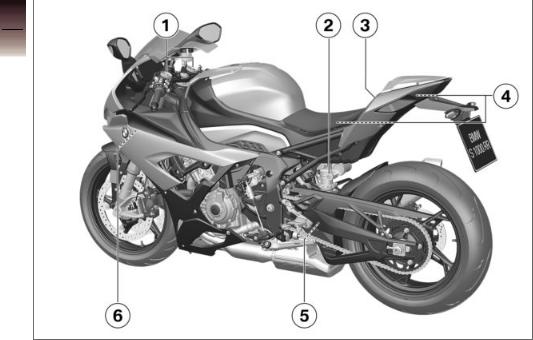
2
18
General views
![]()
General view, left side
1without Dynamic Damping Control (DDC)OE
Adjust the rebound-stage damping for front wheel ( 112).
112).
Adjusting spring preload for front wheel ( 108).
108).
without Dynamic Damping Control (DDC)OE
Adjusting compressionstage damping for front wheel ( 111).
111).
|
2 |
without Dynamic Damp- |
6 Adjusting steering damper |
2 |
|
|
ing Control (DDC)OE |
( 107) |
|||
|
Adjusting compression- |
||||
|
19 |
||||
|
stage damping for rear |
||||
|
wheel ( 113). |
||||
|
without Dynamic Damp- |
||||
|
ing Control (DDC)OE |
||||
|
Adjusting spring preload |
views |
|||
|
for rear wheel ( 109). |
||||
|
with Dynamic Damping |
||||
|
Control (DDC)OE |
General |
|||
|
Adjusting spring preload |
||||
|
for rear wheel ( 110). |
||||
|
3 Lock for tail-hump cover |
||||
|
( 79) |
||||
|
Seat lock ( 80) |
||||
|
4 Table of tyre pressures |
||||
|
Payload table |
||||
|
Chain settings |
||||
|
5 |
without Dynamic Damp- |
|||
|
ing Control (DDC)OE |
Adjusting rebound-stage damping for rear wheel ( 113).
113).
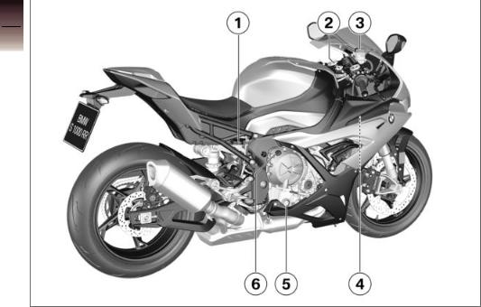
2
20
General views

General view, right side
1Brake-fluid reservoir, rear ( 185)
185)
2Vehicle identification number (on the steering-head bearing)
Type plate (on the steering-head bearing)
3Brake-fluid reservoir, front ( 184)
184)
4Check coolant level ( 187)
187)
5Engine oil level indicator ( 179)
179)
6Oil filler opening ( 181)
181)
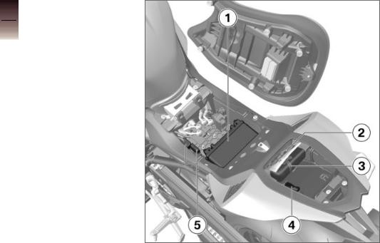
Underneath the seat
1Battery ( 202)
202)
2Rider’s manual
3Toolkit ( 176)
176)
4Diagnostic connector ( 206)
206)
5Fuses ( 205)
205)
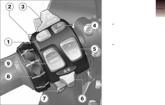
Multifunction switch, left
1DTC Switching off ( 67)
67)
2High-beam headlight and headlight flasher ( 65)
65)
3with cruise controlOE Switching on cruise control ( 70).
70).
4Hazard warning lights system ( 66)
66)
5with riding modes ProOE DTC Adapting ( 145).
145).
6Turn indicators ( 66)
66)
7Horn
8Multi-Controller Controls ( 85)
85)
9MENU rocker switch ( 85)
85)
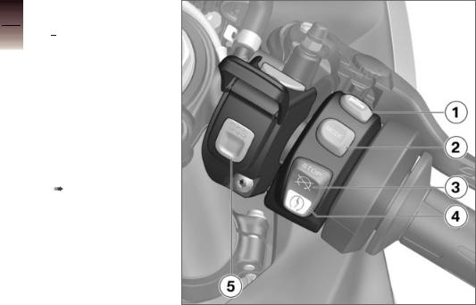
Multifunction switch, right
1 with heated gripsOE Heated handlebar grips ( 78).
78).
2Riding mode ( 68)
68)
3Emergency off switch (kill switch) ( 61)
61)
4Starter button Starting the engine ( 122).
122).
Race start with Launch Control ( 142)
142)
5SOS button
Intelligent emergency call ( 62)
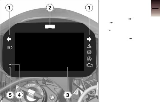
Instrument panel
1Indicator and warning lights ( 28)
28)
2Gearshift light ( 126)
126)
|
3 |
TFT display |
( 29) |
|
( 31) |
||
|
4 |
Alarm system LED |
|
|
with anti-theft alarm |
||
|
(DWA)OE |
||
|
Alarm signal |
( 76) |
5Photosensor (for adapting the brightness of the instrument lighting)

2
26
General views

Status indicators
Indicator and warning lights . . . . . . . . . 28 TFT display in Pure Ride view . . . . . . 29 TFT display in view menu . . . . . . . . . . 31 Warnings . . . . . . . . . . . . . . . . . . . . . . . . . . . 32
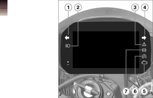
Indicator and warning lights
1Turn indicators, left Operating the turn indicators ( 66).
66).
2High-beam ( 65)
65)
3General warning light ( 32)
32)
4Turn indicators, right
5— with export to EU marketsNV
Malfunction indicator lamp
6DTC ( 52)
52)
7ABS ( 155)
155)
![]()
TFT display in
Pure Ride view
1Hill Start Control ( 55)
55)
2Engine speed display ( 91)
91)
3Speedometer
4Driver info. status line ( 89)
89)
5with cruise controlOE Switching on cruise control ( 70).
70).
6RACE PRO riding mode with riding modes ProOE
Configuration for the race track ( 141)
141)
7Switching Speed Limit Info on or off ( 91).
91).
with riding modes ProOE DTC Adapting ( 145).
145).
8Riding mode ( 68)
68)
9Recommendation to upshift ( 92)
92)
10Gear indicator; «N» indicates neutral.

|
3 |
11 |
Clock ( 93) |
|
|
12 |
Connection status ( 94) |
||
|
13 |
Muting ( 92) |
||
|
30 |
|||
|
14 |
Operator help |
||
|
15 |
Heating stages, handlebar |
||
|
grips ( 78) |
|||
|
Status indicators |

TFT display in view menu
1Hill Start Control ( 55)
55)
2Speedometer
3with cruise controlOE Switching on cruise control ( 70).
70).
4Switching Speed Limit Info on or off ( 91).
91).
with riding modes ProOE DTC Adapting ( 145).
145).
5 RACE PRO riding mode with riding modes ProOE
Configuration for the race track ( 141)
141)
6Riding mode ( 68)
68)
7Driver info. status line ( 89)
89)
8Recommendation to upshift ( 92)
92)
9Gear indicator; «N» indicates neutral.
10Clock
11Connection status

|
3 |
12 |
Muting ( 92) |
|
|
13 |
Operator help |
||
|
14 |
Heating stages, handlebar |
||
|
32 |
|||
|
grips ( 78) |
|||
|
15 |
Menu section |
||
|
Status indicators |
Warnings
Mode of presentation
Warnings are indicated by the corresponding warning lights. Warnings are shown by the general warning light in connection with a dialogue in the TFT display. The ‘general’ warning light is yellow or red, depending on the urgency of the warning.
The general warning light is displayed according to the
most urgent warning.
The possible warnings are listed on the following pages.
Check Control display
The messages shown in the display vary. Different colours and symbols are used depending on priority:
Green CHECK OK 1: no message, optimum values.
White circle with small «i» 2: information.
Yellow warning triangle 3: warning message, value not optimum.
Red warning triangle 3: warning message, value critical

Values display
The symbols 4 displayed vary. Different colours are used depending on assessment. Instead of numerical values 8 with units 7, texts 6 are displayed:
Colour of the symbol
Green: (OK) current value is optimum.
Blue: (Cold!) current temperature is too low.
Yellow: (Low! / High!) current value is too low or too high. Red: (Hot! / High!) current temperature or value is too high.
White: (—) valid value not available. Instead of the value, dashes 5 are displayed.
 NOTICE
The assessment of some values is only possible from a certain journey duration or speed. If a measured value is still not being displayed because the conditions for measurement have not been met, dashes are displayed instead as a placeholder. If there are no valid measured values, there will be no assessment in the form of a coloured symbol.
Check Control dialogue
Messages are output as a Check Control dialogue 1.
If several CC messages with the same priority are present, the messages alternate in the order they occurred until these are acknowledged.
If the symbol 2 is actively being displayed, it can be acknowledged by holding the MultiController to the left.
Check Control messages are dynamically attached as additional tabs on the pages in the menu My vehicle ( 87).
87).
You can go to the message

again as long as the fault per- 3 sists.
34
Status indicators

|
Warnings, overview |
|||
|
Indicator and warning |
Display text |
Meaning |
|
|
lights |
|||
|
General warning |
is displayed in yel- |
Vehicle voltage too low |
( 42) |
|
light shows yellow. |
low. |
||
|
Vehicle voltage |
|||
|
low. |
|||
|
General warning |
is displayed in red. |
Vehicle voltage critical |
( 42) |
|
light shows red. |
|||
|
Vehicle voltage |
|||
|
critical! |
|||
|
General warning |
The faulty light |
Light source faulty ( 43) |
|
|
light shows yellow. |
source is displayed. |
||
|
Alarm system |
Anti-theft alarm battery weak ( 43) |
||
|
battery weak. |
|||
|
General warning |
Alarm system |
Anti-theft alarm battery flat ( 44) |
|
|
light shows yellow. |
battery empty. |
||
|
General warning |
Coolant temper- |
Coolant temperature too high ( 44) |
|
|
light shows red. |
ature too high! |
||

|
Indicator and warning |
Display text |
Meaning |
|
|
lights |
|||
|
The malfunction |
Engine! |
Emissions warning ( 45) |
|
|
indicator lamp lights |
|||
|
up. |
|||
|
General warning |
No communica- |
Engine control failed ( 45) |
|
|
light shows yellow. |
tion with en- |
||
|
gine control. |
|||
|
General warning |
Fault in the en- |
Engine in emergency-operation mode |
|
|
light shows yellow. |
gine control. |
( 45) |
|
|
General warning |
Serious fault |
Serious fault in the engine control |
|
|
light flashes yellow. |
in the engine |
( 46) |
|
|
control! |
|||
|
General warning |
is displayed in yel- |
Tyre pressure in limit range of the per- |
|
|
light shows yellow. |
low. |
mitted tolerance ( 47) |
|
|
Tyre pressure |
|||
|
is not at set- |
|||
|
point. |
|||
|
General warning |
is displayed in red. |
Tyre pressure outside the permitted tol- |
|
|
light flashes red. |
erance ( 48) |
||

|
Indicator and warning |
Display text |
Meaning |
|
lights |
||
|
Tyre pressure |
Tyre pressure outside the permitted tol- |
|
|
is not at set- |
erance ( 48) |
|
|
point. |
||
|
Tyre press. |
||
|
control. Loss |
||
|
of pressure. |
||
|
«—« |
Transmission fault ( 49) |
|
|
General warning |
«—« |
Sensor faulty or system fault ( 49) |
|
light shows yellow. |
||
|
General warning |
RDC sensor bat- |
Battery for tyre pressure sensor weak |
|
light shows yellow. |
tery weak. |
( 50) |
|
General warning |
Drop sensor |
Drop sensor defective ( 50) |
|
light shows yellow. |
faulty. |
|
|
Engine start |
Motorcycle dropped ( 50) |
|
|
not possible. |
||
|
Intell. emerg. |
Emergency call function restricted |
|
|
call failure. |
( 50) |
|

|
Indicator and warning |
Display text |
Meaning |
|
|
lights |
|||
|
Side stand mon- |
Side stand monitoring is faulty ( 51) |
||
|
itoring faulty. |
|||
|
ABS indicator |
ABS self-diagnosis not completed |
||
|
and warning light |
( 51) |
||
|
flashes. |
|||
|
ABS indicator |
ABS deactivated ( 51) |
||
|
and warning light |
|||
|
comes on. |
|||
|
ABS indicator |
Limited ABS |
ABS fault |
( 51) |
|
and warning light |
availability! |
||
|
comes on. |
|||
|
ABS indicator |
ABS failure! |
ABS failed |
( 52) |
|
and warning light |
|||
|
comes on. |
|||
|
ABS indicator |
ABS Pro fail- |
ABS Pro failed ( 52) |
|
|
and warning light |
ure! |
||
|
comes on. |
|||
|
DTC indicator |
DTC intervention ( 52) |
||
|
and warning light |
|||
|
flashes quickly. |
|||
![]()
|
Indicator and warning |
Display text |
Meaning |
|
lights |
||
|
DTC indicator |
DTC self-diagnosis not completed |
|
|
and warning light |
( 52) |
|
|
flashes slowly. |
||
|
DTC indicator |
Off! |
DTC switched off ( 53) |
|
and warning light |
||
|
comes on. |
||
|
Traction con- |
||
|
trol deactiv- |
||
|
ated. |
||
|
DTC indicator |
Traction con- |
DTC fault ( 53) |
|
and warning light |
trol failure! |
|
|
comes on. |
||
|
DTC indicator |
Traction con- |
DTC restricted ( 53) |
|
and warning light |
trol limited! |
|
|
comes on. |
||
|
General warning |
Spring strut |
DDC fault ( 54) |
|
light shows yellow. |
adjustment |
|
|
faulty! |
||
|
Fuel reserve |
Fuel down to reserve ( 54) |
|
|
reached. Go to a |
||
|
filling station soon |
||

|
Indicator and warning |
Display text |
Meaning |
|
lights |
||
|
Green holding sym- |
Hill Start Control active ( 55) |
|
|
bol is displayed. |
||
|
Yellow holding |
Hill Start Control automatically deactiv- |
|
|
symbol flashes. |
ated ( 55) |
|
|
Crossed-out hold- |
Hill Start Control cannot be activated |
|
|
ing symbol is dis- |
( 55) |
|
|
played. |
||
|
The gear indicator |
Gear not trained ( 55) |
|
|
flashes. |
||
|
Turn signal indic- |
Hazard warning lights system is switched |
|
|
ator light flashes |
on ( 56) |
|
|
green. |
||
|
Turn signal indic- |
||
|
ator light flashes |
||
|
green. |
||
|
Gearshift light lights |
Launch Control |
Launch Control not ready ( 56) |
|
up or flashes. |
not av. Clutch |
|
|
too hot. is dis- |
||
|
played. |
||

|
Indicator and warning |
Display text |
Meaning |
|
lights |
||
|
is displayed in |
Service due ( 57) |
|
|
white. |
||
|
Service due! |
||
|
General warning |
is displayed in yel- |
Service-due date has passed ( 57) |
|
light shows yellow. |
low. |
|
|
Service over- |
||
|
due! |
||

Vehicle voltage too low
General warning light shows yellow.
 is displayed in yellow.
Vehicle voltage low. Switch off unneces-
sary consumers.
 WARNING
Failure of the vehicle systems
Risk of accident
 Do not continue your journey.
The battery will not be charged. By continuing to drive on, the vehicle electronics discharge the battery.
 NOTICE
The fuse for the alternator regulator can blow if the 12 V battery is installed incorrectly or if
the terminals are swapped (e.g. when using a starting aid).
Possible cause:
The alternator or alternator drive is faulty, battery is faulty or the fuse for the alternator regulator has blown.
 Have the fault rectified as quickly as possible by a specialist workshop, preferably an authorised BMW Motorrad Retailer.
Vehicle voltage critical
General warning light shows red.
 is displayed in red.
Vehicle voltage critical! Consumers have
been switched off. Check battery condition.
 WARNING
Failure of the vehicle systems
Risk of accident
 Do not continue your journey.
The battery will not be charged. By continuing to drive on, the vehicle electronics discharge the battery.
 NOTICE
The fuse for the alternator regulator can blow if the 12 V battery is installed incorrectly or if the terminals are swapped (e.g. when using a starting aid).
Possible cause:
The alternator or alternator drive is faulty, battery is faulty or the fuse for the alternator regulator has blown.
 Have the fault rectified as quickly as possible by a

specialist workshop, preferably an authorised BMW Motorrad Retailer.
Light source faulty
General warning light shows yellow.
The faulty light source is displayed:
 High beam faulty!
Front left turn indicator faulty! or
Front right turn indicator faulty!
Low-beam headlight faulty!
Front side light faulty!
 Tail light faulty!
 Brake light faulty!
Rear left turn indicator faulty! or
Rear right turn indicator faulty!
Number plate light faulty!
Have it checked by a specialist workshop.
 WARNING
Vehicle overlooked in traffic due to failure of the lights on the vehicle
Safety risk
 Always replace a faulty bulb at the earliest possible opportunity. Consult a specialist workshop, preferably an authorised BMW Motorrad Retailer.
Possible cause:
One or more light sources are faulty.
 Identify the faulty light source through a visual inspection.
  Have LED light sources completely replaced; consult a specialist workshop, preferably an authorised BMW Motorrad Retailer.
Possible cause:
Plug connection disconnected.
 Identify disconnected plug connection.
 Connect disconnected plug connection.
Anti-theft alarm battery weak
with anti-theft alarm (DWA)OE
Alarm system battery weak. No
restrictions. Make

an appointment at a specialist workshop.
 NOTICE
This error message shows briefly only after the Pre-Ride-Check completes.
Possible cause:
The integral battery in the antitheft alarm has lost a significant proportion of its original capacity. There is no assurance of how long the anti-theft alarm can remain operational if the vehicle’s battery is disconnected.
 Seek the advice of a specialist workshop, preferably an authorised BMW Motorrad Retailer.
Anti-theft alarm battery flat
with anti-theft alarm (DWA)OE
General warning light shows yellow.
Alarm system battery empty. No independent
alarm. Make an appointment at a specialist workshop.
 NOTICE
This error message shows briefly only after the Pre-Ride-Check completes.
Possible cause:
The integral battery in the antitheft alarm has lost its entire original capacity. There is no assurance that the anti-theft alarm will be operational if the vehicle’s battery is disconnected.
 Seek the advice of a specialist workshop, preferably an authorised BMW Motorrad Retailer.
Coolant temperature too high
General warning light shows red.
Coolant temperature too high! Check
coolant level. Continue under part. load to cool down.
 ATTENTION
Riding with overheated engine
Engine damage
 Compliance with the information set out below is essential.
Possible cause:
The coolant level is too low.
 Check coolant level (
 187). If the coolant level is too low:
 Allow the engine to cool down.
  Top up coolant (
 188).
188).

 Have the cooling system checked by a specialist workshop, preferably by a BMW Motorrad partner.
Possible cause:
The coolant temperature is too high.
 If possible, ride in the part-load range to cool down the engine.
  If the coolant temperature
is frequently too high, have the fault rectified as soon as possible by a specialist workshop, preferably an authorised BMW Motorrad Retailer.
Emissions warning
The malfunction indicator lamp lights up.
Engine! Have it checked by a
specialist workshop.
Possible cause:
The engine control unit has diagnosed a fault which affects the pollutant emissions.
 Have the fault rectified by a specialist workshop, preferably an authorised BMW Motorrad Retailer.
 You can continue riding; pollutant emissions are higher than the threshold values.
Engine control failed
General warning light shows yellow.
No communication with engine control. Multiple sys. affected. Ride carefully to the next spe-
cialist workshop.
Engine in emergencyoperation mode
General warning light shows yellow.
Fault in the engine control. Riding at
mod. speed pos. Ride carefully to next specialist workshop.
 WARNING
Unusual ride characteristics when engine running in emergency-operation mode
Risk of accident
 Avoid accelerating sharply and overtaking.
Possible cause:
The engine control unit has diagnosed a fault. In exceptional cases, the engine stops and refuses to start. Otherwise, the engine runs in emergency operating mode.

 You can continue to ride, but bear in mind that the usual engine power or the full range of engine rpm might not be available.
 Have the fault rectified as quickly as possible by a specialist workshop, preferably an authorised BMW Motorrad Retailer.
Serious fault in the engine control
General warning light flashes yellow.
Serious fault in the engine control!
Riding at mod. speed pos. Damage possible. Have checked by workshop.
 WARNING
Engine damage when running in emergency-operation mode
Risk of accident
 Ride slowly, avoid accelerating sharply and overtaking.
 If possible, have the vehicle picked up and have the fault rectified by a specialist workshop, preferably an authorised BMW Motorrad Retailer.
Possible cause:
The engine control unit has diagnosed a fault which may cause severe secondary faults. The engine is in emergency-operation mode.
 It is possible to continue to ride but not recommended.
 Avoid high load and rpm ranges if possible.
 Have the fault rectified as quickly as possible by a specialist workshop, preferably an authorised BMW Motorrad Retailer.
Tyre pressure
with tyre pressure control (RDC)OE
In addition to the MY VEHICLE menu screen and the Check Control messages, there is also the TYRE PRESSURE screen for the display of the tyre inflation pressures:
The left values refer to the front wheel, the right values to the rear wheel.
The pressure difference is displayed via the actual and target tyre pressure.

Only dashes are displayed immediately after the ignition is switched on. The transmission of the tyre pressure values begins only after the first time the following minimum speed has been exceeded:
RDC sensor is not active
min 30 km/h (The RDC sensor does not send its signal to the vehicle until the vehicle has exceeded a minimum speed.)
The tyre pressures are shown in the TFT
display as temperature compensated and always refer to the following tyre air temperature:
20 °C
If the tyre symbol is additionally displayed in yel-
low or red, this is a warning. The pressure difference is highlighted with an exclamation point in the same colour.
If the value in question is close to the limit of the
permissible tolerance range, the ‘General’ warning light also lights up in yellow.
If the tyre pressure registered by the sensor is
outside the permissible tolerance range , the ‘General’ warning light flashes red.
For further information about the BMW Motorrad RDC, see the section entitled «Engineering details» from page ( 170) onwards.
Tyre pressure in limit range of the permitted tolerance
with tyre pressure control (RDC)OE
General warning light shows yellow.
 is displayed in yellow.
Tyre pressure is not at setpoint. Check
tyre pressure.
Possible cause:
Measured tyre pressure is close to the limit of permitted tolerance.
 Correct tyre pressure.
 Before adjusting the tyre pressure, observe the information on temperature compensation and pressure adaptation in the section entitled «Engineering details»:

 Temperature compensation (
 171)
171)
 Pressure adaptation (
 171)
171)
 Find the correct tyre pressures in the following places:
On the back cover of the rider’s manual
Instrument cluster in the TYRE PRESSURE view
Sign under the seat
Tyre pressure outside the permitted tolerance
with tyre pressure control (RDC)OE
General warning light flashes red.
 is displayed in red.
Tyre pressure is not at setpoint. Stop
immediately! Check tyre pressure.
Tyre press. control. Loss of pressure.
Stop immediately! Check tyre pressure.
 WARNING
Tyre pressure outside the permitted tolerance.
Risk of accident, degradation of the vehicle’s driving characteristics.
 Adapt your style of riding accordingly.
Possible cause:
Measured tyre pressure is outside permitted tolerance.
 Check the tyre for damage and to ascertain whether the vehicle can be ridden with the tyre in its present condition.
If the vehicle can be ridden with the tyre in its present condition:  Correct the tyre pressure at the
earliest possible opportunity.
 Before adjusting the tyre pressure, observe the information on temperature compensation and pressure adaptation in the section entitled «Engineering details»:
 Temperature compensation (
 171)
171)
 Pressure adaptation (
 171)
171)
 Find the correct tyre pressures in the following places:
On the back cover of the rider’s manual
Instrument cluster in the TYRE PRESSURE view
Sign under the seat
 Have the tyre checked for damage by a specialist workshop, preferably an authorised BMW Motorrad Retailer.
If you are unsure whether the vehicle can be ridden with the tyre in its present condition:
 Do not continue your journey.
  Notify the breakdown service.
 Loading…
- Manuals
- Brands
- BMW Manuals
- Motorcycle
- S 1000 RR —
- Rider’s manual
-
Contents
-
Table of Contents
-
Troubleshooting
-
Bookmarks
Quick Links
BMW Motorrad
The Ultimate
Riding Machine
Rider’s Manual (US Model)
S 1000 RR
Related Manuals for BMW S 1000RR
Summary of Contents for BMW S 1000RR
-
Page 1
BMW Motorrad The Ultimate Riding Machine Rider’s Manual (US Model) S 1000 RR… -
Page 2
Motorcycle/Retailer Data Motorcycle Data Retailer Data Model Contact in Service Ms./Mr. Vehicle identification number Phone number Color number Initial registration Retailer’s address/phone number (com- License plate pany stamp) -
Page 3
About this Rider’s Manual BMW Motorrad. Please read this Rider’s Manual carefully before starting to use your new BMW. It contains im- portant information on how to operate the controls and how to get the most benefit from your BMW’s advanced technical fea- tures. -
Page 4: Table Of Contents
Table of Contents 3 Displays ….21 Cruise control ….57 Warning and indicator Speed warning .
-
Page 5
Refueling ….90 Battery ….185 8 Technology in de- Secure motorcycle for trans- tail . -
Page 6
Reporting safety defects ….216 BMW Motorrad Service . . . 217 BMW Motorrad Mobility Services ….217 Maintenance proce- dures . -
Page 7: General Instructions
General instructions Overview ……6 Abbreviations and symbols ..6 Equipment .
-
Page 8: Overview
When the time comes to sell claims may be denied as a result. your BMW, please remember NOTICE Special informa- Anti-Lock Brake System. to hand over this Rider’s Manual; tion on operating and in-…
-
Page 9: Equipment
Optional accessory. may vary from the descriptions in If your BMW is equipped with BMW Motorrad op- this Rider’s Manual. In addition, options or accessories not de- tional accessories can…
-
Page 11: Overviews
Overviews General view, left side ….11 General view, left side with DDC ..13 General view, right side … . . 15 Multifunction switch, left .
-
Page 13: General View, Left Side
General view, left side without Dynamic Damp- ing Control (DDC) Adjuster for spring preload, front ( Adjusting front compres- sion damping (red scale) without Dynamic Damp- ing Control (DDC) Adjusting rear compres- sion damping (red scale) Adjuster for spring preload, rear ( Seat lock ( Tire inflation pressure table…
-
Page 15: General View, Left Side With Ddc
General view, left side with DDC with Dynamic Damping Control (DDC) Adjust spring preload on front wheel ( Seat lock ( Tire inflation pressure table Load capacity table Chain adjustment values Adjuster for spring preload, rear ( Engine oil level indicator 159) Connector for optional ac- cessories (…
-
Page 17: General View, Right Side
General view, right side without Dynamic Damp- ing Control (DDC) Brake-fluid reservoir, rear Adjusting rear rebound- 164) stage damping (yellow Vehicle identification num- scale) ( ber and type plate (on steering head at right) Brake-fluid reservoir, front 163) Adjusting rebound-stage damping without Dynamic Damp- ing Control (DDC)
-
Page 18: Multifunction Switch, Left
Multifunction switch, left Deactivating ABS ( ASC ausschalten ( with Dynamic Traction Control (DTC) Deactivating DTC ( High-beam headlight and headlight flasher ( Start time recording 100) with cruise control Cruise control ( Hazard warning flashers with Dynamic Traction Control (DTC) Adjusting DTC ( 127) Turn indicator (…
-
Page 19
Setting clock ( Resetting tripmeter Selecting displays ( Individualizing lap timer 100) Selecting submenu 113) -
Page 20: Right
Multifunction switch, right with heated handlebar grips Heated grip ( Selecting riding mode Emergency on/off switch (kill switch) ( Starter button Starting engine ( with Pro riding modes Launch Control ( 128) Speed limiter for pit lane 130)
-
Page 21: Underneath Seat
Underneath seat Battery ( 185) with anti-theft alarm sys- tem (DWA) Different position of battery terminals: shifted forward Helmet holder ( Luggage straps ( Onboard tool kit ( 156) Fuse box ( 188) Rider’s Manual (US Model)
-
Page 22: Instrument Cluster
Instrument cluster Indicator and warning lights Tachometer Shiftpoint light ( Photosensor (for adjusting brightness of instrument lighting) with anti-theft alarm sys- tem (DWA) DWA LED ( Multifunction display…
-
Page 23: Displays
Displays Warning and indicator lights..22 Multifunction display ….23 Warning lights ….. . 24…
-
Page 24: Warning And Indicator
Warning and indicator lights ASC indicator and warning light ( with Dynamic Traction Control (DTC) DTC indicator light ( ABS indicator and warning light ( Turn indicator, left Universal warning light, appears together with warnings in multifunction display ( Turn indicator, right Fuel reserve ( Neutral indicator light High-beam headlight…
-
Page 25: Multifunction Display
Multifunction display Speedometer Coolant temperature Odometer ( Clock ( with heated handlebar grips Heated handlebar grips Gear indicator display, «N» indicates «neutral». Riding mode RAIN SPORT RACE Setting riding mode with Pro riding modes Additional riding modes SLICK USER…
-
Page 26: Warning Lights
Warning lights If several warnings are active, all NOTICE corresponding warning lights and Display warning symbol are displayed; Refer to Chapter 7 for informa- Warnings are displayed with ap- warnings appear alternately. tion regarding the display modes propriate warning lights. You will find an overview of the available for track use.
-
Page 27
Overview of warning indicators Warning and indicator Warning symbols in the Meaning lamps display panel EWS! lights up red is displayed Electronic immobilizer is active ( flashes red Coolant tempera- Coolant temperature too high ( ture display flashes lights up Engine in emergency-operation mode flashes yellow Severe fault in the engine management… -
Page 28
Warning and indicator Warning symbols in the Meaning lamps display panel LAMPS! lights up yellow is indi- Taillight and lights for parking lights de- cated fective ( Front lights defective ( VDS! lights up yellow is shown in Motorcycle has fallen over ( the empty display VDS! lights up yellow… -
Page 29
Warning and indicator Warning symbols in the Meaning lamps display panel flashes slowly ASC self-diagnosis not completed lights up ASC switched off ( lights up ASC error ( flashes rapidly DTC intervention ( flashes slowly DTC self-diagnosis not completed lights up DTC switched off ( lights up DTC error (… -
Page 30
Warning and indicator Warning symbols in the Meaning lamps display panel DWALO! lights up yellow is dis- DWA battery charge level low ( played DWA! lights up yellow is displayed DWA battery drained ( SPEED! Shiftpoint light is dis- Speed warning ( played flashes or remains on continuously… -
Page 31
In exceptional cases, the frequently be too high, have placed, preferably by an autho- engine stops and can no longer the fault rectified as quickly rized BMW Motorrad retailer. be started. as possible by an authorized Coolant temperature too workshop, preferably an autho-… -
Page 32
WARNING Suppress the fault message source eliminated by a special- SETUP in the submenu ized service facility, preferably Overlooking the motorcy- EQUIPMENT WARN with the an authorized BMW Motorrad cle in traffic due to the light LAMP OFF parameter. Retailer. -
Page 33
Replacing light source for left- failing. cialist service facility, preferably hand parking light ( 178). Safety risk an authorized BMW Motorrad Replacing right-hand parking Replace defective bulbs as retailer. light light source ( 179). soon as possible; it is best… -
Page 34: Abs Error
Motorcycle has fallen over Possible cause: Contact an authorized service facility, preferably an authorized The ABS system has been deac- General warning light shows BMW Motorrad retailer. tivated by the rider. yellow. Activating ABS ( 51). ABS self-diagnosis not VDS!
-
Page 35: Asc Error
Possible cause: ASC error preferably an authorized BMW Motorrad retailer. ASC indicator and warning ASC self-diagnosis rou- light lights up. tine not completed ASC intervention Possible cause: ASC indicator and warning The ASC function is not avail- light flashes rapidly.
-
Page 36
Possible cause: Possible cause: DTC indicator light flashes rapidly. The DTC system has been deac- DTC self-diagnosis not DTC has detected instability at tivated by the rider. completed the rear wheel and responded by Switching on DTC ( 53). reducing the torque. The warn- The DTC function is not avail- DTC error ing light flashes longer than the… -
Page 37
Possible cause: preferably an authorized NOTICE BMW Motorrad retailer. The DDC control unit has de- tected an error. This fault message is only shown DDC error Have the malfunction corrected for a short time immediately fol- with Dynamic Damping Control as soon as possible at an lowing the Pre-Ride-Check. -
Page 38
Contact an authorized service for a short time immediately fol- facility, preferably an authorized Enter a new maximum speed. lowing the Pre-Ride-Check. BMW Motorrad retailer. Possible cause: Launch Control not ready Encoding missing The anti-theft alarm system bat- with Pro riding modes tery is completely discharged. -
Page 39: Service Display
Fuel reserve connected for a longer time. Consult a certified workshop, Approx. 1.1 gal (Approx. 4 l) preferably an authorized BMW Motorrad retailer, for Refueling ( 90). If service is due within 1,000 km setting of the date. (700 miles), the remaining…
-
Page 40: Cruising Range
The determined range is dicates the distance that can still an approximate reading. be driven with the remaining fuel. BMW Motorrad therefore This distance is calculated based recommends that you do not on fuel quantity and average con- try to use the full range before sumption.
-
Page 41: Operation
Operation Steering and ignition lock … 40 Cruise control ….. . . 57 Ignition .
-
Page 42: Steering And Ignition Lock
Ignition Steering and ignition lock Switch on ignition Keys You are provided with 2 ignition keys. Should you lose your keys please refer to the information regard- ing the electronic immobilizer (EWS) ( 41). Turn the ignition key to posi- A single key fits the steering and tion 1 while moving the handle- ignition lock, the fuel filler cap…
-
Page 43: Electronic Immobilizer
Switch off ignition recognized as «authorized» for Replacement and spare keys are your motorcycle. only available through an autho- rized BMW Motorrad retailer. NOTICE The keys are part of an inte- grated security system, so the A further key attached to the…
-
Page 44: Lights
Lights WARNING Parking lights Operation of the emergency The parking lights come on au- ON/OFF switch when riding. tomatically when the ignition is Danger of falling due to blocking switched on. of rear wheel. Do not operate the emergency NOTICE ON/OFF switch when riding.
-
Page 45: Hazard Warning Flashers
Hazard warning Ignition can be switched off. Switch on ignition and press flashers button 1 again to switch off Switching on hazard hazard warning flashers. warning flashers Turn indicator Switch on ignition. Operating turn indicators NOTICE Switch on ignition. The hazard warning flashers Immediately after switching off place a strain on the battery.
-
Page 46
NOTICE The turn indicators automati- cally switch off when the defined driving time and distance have been reached. The defined rid- ing time and distance can be set by an authorized BMW Motorrad retailer. -
Page 47: Multifunction Display
Multifunction display Overview — Solid line: briefly press button. ‑ ‑ Dotted line: press and hold button. Odometer Standard display Select displays in multi- function display ( LAP TIMER ( LIMIT ( Factory setting for WARN SPEED ( 118) RACE INFO ( 103) SETUP MENU ( 111)
-
Page 48
RANGE Selecting displays in Cruising range Repeatedly press SET 2 until TRIP 1 desired display is selected. Trip distance 1 multifunction display TRIP 2 The following displays are avail- Trip distance 2 Switch on ignition. able: Average consumption All information required for LAPTIMER: The lap times volume per distance or vice operation on public roads is… -
Page 49: Resetting Tripmeter
LIMIT is shown, press and Press and hold TRIP 1 until hold SET 2 to set current driv- tripmeter has been reset. ing speed as new limit. Trip mileage = RACE INFO ENTER Resetting average data SETUP MENU ENTER shown, press and hold SET 2 Switch on ignition.
-
Page 50: Alarm System
The alarm can be set off by: turn indicators flash. The alarm sition. tone type can be adjusted by Switch on ignition. an authorized BMW Motorrad Turn indicators light up once. retailer.
-
Page 51
DWA AUTO Confirmation tone sounds once to the start and finally to the de- Parameter 5 and (if programmed). sired display. its current value 6 are dis- played. DWA is now switched off. Press and hold SET 2 to open the menu. -
Page 52: Clock
DWA AUTO OFF : DWA is Minutes 4 flash. deactivated. Briefly press TRIP 1 to in- Press and hold SET 2 to save crease minutes. the set value. Briefly press TRIP 2 to de- The value 6 no longer flashes. crease minutes.
-
Page 53: Automatic Stability Control
NOTICE seconds. out, and starts to flash if self-diagnosis has not been com- ABS indicator light contin- The BMW Motorrad Race ABS pleted. ues to be lit up. function can also be deactivated If the coding plug for the while driving.
-
Page 54: Control
ASC indicator and warning ASC indicator and warning NOTICE light continues to be lit up. light remains off or contin- ues to flash. The Automatic Stability Control ASC is deactivated. (ASC) can also be deactivated ASC activated. while riding. Switch on ASC As an alternative, the ignition can also be switched off and then on again.
-
Page 55: Riding Mode
Use of the riding modes until the DTC —indicator light 2 out, and if self-diagnosis changes its display behavior. BMW Motorrad has developed 5 has not been completed, it be- DTC indicator light starts to riding scenarios for your motor- gins to flash.
-
Page 56
Setting riding mode Riding on wet roads. Sporty riding on dry roads. Switch on ignition ( 40). Riding on racetracks with se- ries tires. with Dynamic Traction Control (DTC) Riding on racetracks with se- ries tires. Riding on racetracks with rac- The selection arrow 2 and the ing tires while taking settings selectable riding modes 3 are… -
Page 57
Selection arrow 2 and inactive riding modes are hidden. The new riding mode is acti- vated during operation under the following conditions: The throttle grip is in the neu- tral position. The brake lever is not being operated. The following riding modes can with Pro riding modes WARNING be selected:… -
Page 58
ually displayed, but instead only with Pro riding modes Do not use the encoding plug after the following events for a on public roads. USER : Riders can combine limited time: the settings from all available Switch off ignition ( 41). -
Page 59: Cruise Control
Cruise control Storing speed with cruise control Switching on cruise control To do so, press in locking de- vice 2 and pull off cap. Briefly press button 1 forward. Insert coding plug. Adjustment range for Switch on the ignition. cruise control For safety reasons, after the coding plug is connected, the 19…130 mph (30…210 km/h)
-
Page 60
Acceleration Decreasing speed Deactivating cruise control Actuate brakes, clutch or throt- tle grip (take back throttle be- yond back position) to deacti- vate cruise-control system. NOTICE When changing gear using the Pro Gear-shift Assistance func- Briefly press button 1 forward. Briefly press button 1 back- tion, the cruise-control system ward. -
Page 61: Speed Warning
Resuming former cruising Indicator light for cruise- Speed warning ( 118) control system lights up. speed Switching off cruise control Briefly press SET 2 repeat- Briefly push button 1 back to LIMIT edly until is shown in return to the speed saved be- display.
-
Page 62: Heated Handlebar Grips
To set current speed as new When the preset speed is ex- To deactivate the speed warn- limit: press and hold SET 2. ceeded, the shiftpoint light 1 re- ing: Press and hold TRIP 1 un- sponds by lighting up or flashing appears in the display.
-
Page 63: Rider And Passenger Seats
Rider and passenger NOTICE seats The increase in power Removing hump cover consumption caused by the with passenger seat cover heated grips can drain the battery if you are riding at low Park motorcycle, ensuring that engine speeds. If the battery is support surface is firm and inadequately charged, the heated level.
-
Page 64: Removing Passenger Seat
Installing hump cover Install the passenger seat Lock lock with ignition key. with passenger seat cover Removing passenger seat Park motorcycle, ensuring that support surface is firm and level. Mount passenger seat in mounts 1 on left and right. Mount hump cover in mounts 1 on left and right.
-
Page 65: Helmet Holder
Installing driver’s seat Lock seat lock with ignition key. Removing rider`s seat Press cover of driver’s seat over screw sockets toward Mount rider`s seat in mount 2, front somewhat and hold in then position over screw sock- place. ets 3. When doing so, make Press cover of driver’s seat Install screws 1.
-
Page 66: Luggage Straps
Luggage straps Securing luggage on motorcycle Remove passenger seat 62). Turn over passenger seat. Use luggage loops 1, e.g. in ATTENTION conjunction with passenger footrests, to lash luggage onto Incorrect positioning of the passenger seat. When doing helmet lock. so, make sure that the rear trim Fairing scratched.
-
Page 67: Setting
Setting Mirrors ……66 Headlight ……66 Brakes .
-
Page 68: Mirrors
If there are doubts as to the cor- sition by turning it. rect headlight range, have the adjustment checked by a spe- Headlight cialized workshop, preferably by an authorized BMW Motorrad Adjusting headlight for retailer. RHD/LHD traffic This motorcycle’s headlight fea- Brakes tures a symmetrical low beam.
-
Page 69: Steering
Steering Basic steering damper NOTICE Adjusting steering damper adjustment setting The adjusting screw can be Opens at 8 clicks (starting at turned more easily if you push fully closed) (Highway opera- the brake lever forward when tion) doing so. Opens at 5 clicks (starting at Adjustment options: fully closed) (Racetrack) From position 1: Largest dis-…
-
Page 70
Adjusting spring preload Load motorcycle with driver. on front wheel With the assistance of a helper, measure distance D between without Dynamic Damping points 1 and 2 again and cal- Control (DDC) culate difference (spring deflec- tion) between the measured Park motorcycle, ensuring that values. -
Page 71
Ensure that settings on left and Measure distance D between right sides are identical. lower edge 1 of immersion tube and front axle 2. Adjusting spring preload Load motorcycle with driver. on front wheel Measure distance D between with Dynamic Damping Control points 1 and 2 with assistance (DDC) of a 2nd person. -
Page 72
Adjusting spring preload Adjustment of spring at rear wheel preload dependent on without Dynamic Damping loading Control (DDC) Spring deflection of rear wheel Park motorcycle, ensuring that 0.31…0.47 in (8…12 mm) (With support surface is firm and rider 187 lbs (85 kg)) level. -
Page 73
To increase the spring deflec- Switch on ignition. carrier and screw 2 of chain tion (reduce spring preload), guard. Start engine to avoid discharg- use the tool from the onboard ing battery. Load motorcycle with driver. tool kit to turn the adjustment With the assistance of a helper, NOTICE ring 2 in direction B. -
Page 74: Damping
Damping Setting Damping must be adjusted to the road conditions and the spring preload. A rough road surface requires softer damping than a smooth road surface. An increase in spring preload To decrease the spring deflec- Adjust compression damping requires firmer damping, a re- tion (increase spring preload), with adjusting screw 1 and red duction in spring preload re-…
-
Page 75
ing 2 points to a higher scale ing 2 points to higher figure on scale. figure. To decrease damping: turn To decrease damping: turn adjusting screw with tool from adjusting screw with tool from onboard tool kit so that mark- onboard tool kit so that mark- ing 2 points to lower figure on ing 2 points to a lower figure… -
Page 76
ing 2 points to a higher scale Factory settings for figure. jounce/rebound at front To decrease damping: turn adjusting screw with tool from Position 4 onboard tool kit so that mark- ing 2 points to a lower figure Adjusting compression on the scale. -
Page 77: Ddc
ing 2 points to a higher scale Factory settings for figure. jounce/rebound at rear To decrease damping: turn adjusting screw with tool from Position 4 onboard tool kit so that mark- ing 2 points to a lower figure on the scale. Setting Rebound stage, basic Damping must be adjusted to the…
-
Page 78
Park motorcycle, ensuring that Adjust damping as desired with NOTICE support surface is firm and TRIP 1 and SET 2. level. +1 … +7 : Damping increase Damping is adjusted and saved Select submenu ( 113). in a maximum of seven steps separately for all riding modes in SETUP DDC-SYS (harder). -
Page 79
SETUP DDC-SYS DMP: sub- The value next to During the alignment, do not sit menu has been selected. flashes. on the motorcycle and remove any cargo or luggage. Adjust damping as desired with FRONT DMP Adjusting TRIP 1 and SET 2. Select submenu ( 113). -
Page 80
CALIB DONE is displayed in line 3 and 4. If CALIB FAIL is displayed: Repeat alignment. CALIB DONE is not displayed after repeated calibration, please contact a BMW authorized workshop, preferably an authorized BMW Motorrad retailer. -
Page 81: Riding
Riding Safety instructions ….80 Observe checklist ….81 Starting .
-
Page 82: Safety Instructions
Your authorized cycle: Burn hazard BMW Motorrad retailer will be Settings of spring-strut and happy to advise you and has shock absorber system the correct clothing for every CAUTION Imbalanced load purpose.
-
Page 83: Observe Checklist
Catalytic converter Danger of overheating Observe checklist If misfiring causes unburned fuel Use the following checklist to ATTENTION to enter the catalytic converter, check your motorcycle at regu- there is a danger of overheating lar intervals. Engine idling for a lengthy and damage.
-
Page 84: Starting
Starting to disengage clutch and twist with Dynamic Damping Control (DDC) throttle grip slightly. Starting engine Adjusting spring preload at rear Switch on ignition. wheel ( 71). Pre-Ride-Check is carried out. with Dynamic Damping Control (DDC) ABS self-diagnosis is Adjusting damping on rear performed.
-
Page 85
Phase 2 ABS self-diagnosis The universal warning light changes from yellow to red. The readiness for operation of the BMW Motorrad Race ABS Phase 3 is checked by the self-diagnosis. The tachometer needle drops The self-diagnosis routine runs back to zero. -
Page 86
The self-diagnosis routine Phase 2 is determining whether ASC self-diagnosis Check wheel sensors while BMW Motorrad ASC is ready for completed starting off. operation. The self-diagnosis The ASC symbol is no longer ABS indicator light flashes. routine runs automatically when displayed. -
Page 87: Breaking In
The self-diagnosis routine BMW Motorrad retailer. is determining whether Watch all warning and indicator BMW Motorrad DTC is ready for lights on the display. Breaking in operation. The self-diagnosis DTC self-diagnosis not Engine routine runs automatically when completed you switch on the ignition.
-
Page 88: Brake Pads
This WARNING speed monitoring function is switched off during the running- New brake pads. in check by your authorized Extension of the braking distance. BMW Motorrad retailer. Accident hazard. Brake early.
-
Page 89: Shifting Gears
Shifting gears makes the decision as to when Shiftpoint light goes out: shift- ing speed reached to change gear. Shiftpoint light NOTICE The engine rpm limits and the upshift light’s display characteris- More detailed information on Pro tics can both be adjusted in the Gear-shift Assistance can be SETUP menu.
-
Page 90: Brakes
Locking up of the front wheel gear change. change gear and initiates gear- is prevented by BMW Motorrad shift assistance. Brakes Race ABS. When driving at constant With the frequently instructed…
-
Page 91: Parking Your Motorcycle
Wet, soiled brakes road surface. Due to the miss- Brake early until the full braking ing wheel load, the ABS must action is available again. Moisture and dirt on the brake already prevent a tendency of the rotors and the brake pads result Parking your front wheel to lock up with min- in a decrease in the braking ac-…
-
Page 92: Refueling
additives, e.g. manganese or Alternative fuel quality ATTENTION iron. Loading of the side stand ATTENTION Super unleaded (minor restric- with additional weight. tions with regard to power and Component damage cause by Use of Ethanol E85 as fuel. fuel consumption) (max. 10 % tipping over.
-
Page 93
Do not overfill the fuel tank. NOTICE ATTENTION When refueling after running on fuel reserve, the resulting total Fuel attacks plastic surfaces. fuel quantity must be greater Surfaces become unattractive or than the fuel reserve, so that the cloudy. new filling level is detected and Immediately clean plastic parts the fuel warning light is switched after contact with fuel. -
Page 94: Secure Motorcycle For Transport
Fuel reserve Approx. 1.1 gal (Approx. 4 l) Press fuel tank cap down firmly to close. Remove key and close protec- tive cap. Secure motorcycle for ATTENTION ATTENTION transport Motorcycle tips to the side Pinching of components. Protect all component surfaces when raising.
-
Page 95
Fasten rear straps on both sides to the passenger foot- pegs and then tighten them. Tension all straps evenly; the motorcycle should be pulled down against its springs with the suspension compressed as much as possible. -
Page 97: On The Racetrack
On the racetrack Display for racing mode … . . 96 Shift pattern reversal ….136 LAPTIMER .
-
Page 98: Display For Racing Mode
Display for racing mode Multifunction display Current angle of inclination during cornering Direction for angle of incli- nation \ = left | = vertical / = right Maximum angle of inclina- tion for left and right Factory setting for BANK DISP ( 119) ABS control intervention…
-
Page 99
DTC torque reduction with Dynamic Traction Control (DTC) Factory setting for DTC DISP ( 119) DTC setting with Dynamic Traction Control (DTC) Adapt DTC ( 127) -
Page 100: Laptimer
LAPTIMER LAP TIMER The fastest of the stored laps, marked with «BESTLAP». The display in these lines Multifunction display can be switched over. The all-time best lap time, without a marking. Individualize LAPTIMER 100). The running time of the current lap.
-
Page 101
Overview of LAP TIMER — Solid line: briefly press button. ‑ ‑ Dotted line: press and hold button. Odometer Standard display Select displays in multi- function display ( 46). Individualize LAPTIMER 100). Start time recording 100). Interrupt/continue time en- try ( 101) -
Page 102
Individualizing LAPTIMER LAPTIMER display structure When driving over Start/Finish 121) line, press button 1 again to start recording for next race Starting time recording lap. The data of the preceding race The LAPTIMER is opened. lap will be saved. 2 restarts at 00:00:00 If the display mode is exited during a recording, then the… -
Page 103
Interrupting time entry The infrared receiver available as an optional accessory must Time recording is running. be connected to the connector for optional accessories under the right-hand fairing side panel 138). In the SETUP RACETRACK, the LAPTIMER trigger mode must be set to LAPTM TRIG AUTO or LAPTM TRIG EX- Press and hold TRIP 1 to stop TERN (… -
Page 104
have been deleted from the better than that of the previous RACE INFO fastest lap then a new fastest lap can be anticipated. The «fastest is displayed. lap» light 1 lights up. Fastest lap expected This function must be activated SETUP RACETRACK in the menu (… -
Page 105: Race Info
RACE INFO RACE INFO Part 1 — Solid line: briefly press button. ‑ ‑ Dotted line: press and hold button. Delete all-time best lap. Information on the current best lap. Three displays in alterna- tion. Information on each race lap ( 106) Deleting currently best lap.
-
Page 106
RACE INFO Part 2 — Solid line: briefly press button. ‑ ‑ Dotted line: press and hold button. Information on lap 01. Select saved lap ( 105). Information on each race lap ( 106) Delete lap ( 108). Information on lap 02. Total of all lap times and lap distances. -
Page 107
Selecting saved lap they are displayed in the reverse order: RACE INFO is displayed. BEST- All-time best lap time EVER BEST Best stored lap time LAST Last stored lap time LAP 01 All other stored laps … LAP 60 The totals of all saved lap times and lap distances TOTAL Delete the stored data… -
Page 108
Information on each race In alternation for the in- dicted lap: Top speed (max) Average speed (Ø) Minimum speed (min) Maximum angle of incli- nation for left and right of indicated lap Race lap to which dis- played data refer Lap time of displayed race In alternation for the in- dicted lap:… -
Page 109
ABS control intervention: «ABS» displayed = lap with ABS control intervention «ABS» hidden = lap with- out ABS control interven- tion Maximum deceleration in the indicated lap Maximum DTC torque re- duction in the indicated lap 10 DTC setting in the indi- cated lap 11 Riding mode in the indi- cated lap… -
Page 110
BEST-EVER Clearing recording recording that has already been is deleted: —:—:— deleted. RACE INFO is displayed. All recordings have now been Deleting lap deleted. RACE INFO EXIT is dis- RACE INFO is displayed. played. All-time best lap BEST- The all-time best lap ( EVER ) is the fastest of all recorded racing laps and is… -
Page 111
BEST Exiting RACE INFO Activating standard : The lap that previously had been the second best lap display is adopted as the new best lap. LAST : The lap that previously had been the second-to-the- last lap is adopted as the new last lap. -
Page 112
LIMIT Pressing and holding TRIP 1 switches the speed warn- LIMIT OFF ing off ( is displayed. -
Page 113: Setup Menu
SETUP MENU Overview SETUP MENU — Solid line: briefly press button. ‑ ‑ Dotted line: press and hold button. Select submenu ( 113) Display submenu with Dynamic Damping Control (DDC) SETUP DDC-SYS 113) Set parameter ( 115) Display submenu SETUP EQUIPMENT 113) Display submenu SETUP RACETRACK…
-
Page 114
Display submenu Only with USER riding mode active with Pro riding modes SETUP USER-MODE 115) Reset all parameters FAC- TORY RESET Exit SETUP MENÜ Exit settings ( 116) -
Page 115
Selecting submenu Briefly press TRIP 1 or SET 2 With spring travel sensor for repeatedly until desired sub- front forks: Front rebound- FRONT REB menu is displayed. stage damping Press and hold SET 2 to open With spring travel sensor for desired submenu. -
Page 116
UNIT CLOCK 24 or leave deactivated Switch the display for the cur- DWA AUTO OFF UNIT CLOCK 12 rent and maximum delay on BRAKE DISP ON or off Set time display SETUP RACETRACK BRAKE DISP OFF CLOCK TIME Set brightness Submenu for switching over SETUP RACETRACK DISP BRIGHT… -
Page 117
TRIG EXTERN Display duration for : Operation Dynamic traction control for DTC RAIN last stopped lap time only via infrared receiver. wet roads LAPTM HOLD with Pro riding modes Sport mode for Dy- Anti-rebound time (waiting namic Damping Control Adjust the speed for the pit DDC SPORT time until new lap can be PIT LIMIT …… -
Page 118
Exiting settings Repeatedly press TRIP 1 or SETUP MENU SET 2 until EXIT is displayed. Press and hold SET 2 to exit SETUP MENU SETUP MENU ENTER indicated. Press and hold SET 2 until dis- played parameter begins to Press and hold TRIP 1 flash. -
Page 119: Setup Ddc-Sys
-7 … +7 Reading display range Factory setting: 0 -7 (soft) … +7 (stiff) Factory setting: 0 NOTICE The spring travel sensor required for the separate adjustment of the rebound and compression stage is not offered by BMW Motorrad. It is available…
-
Page 120: Setup Equipment
Further SETUP EQUIPMENT Speed warning information can be requested Display brightness under «hp-race-support@bmw- motorrad.com». Leveling sensor calibration LIMIT The speed is set in the display. If the riding speed Five different intensities are avail- SPEED! exceeds this limit,…
-
Page 121
Light error Lean angle Dynamic Traction Control with Dynamic Traction Control (DTC) If the turn indicators are removed Adjustment of the display for an- or the license plate carrier is de- gle of inclination: angle of incli- tached for track use, the vehicle’s nation, direction for angle of incli- Adjustment of the displays for electronic monitoring system will… -
Page 122: Setup Racetrack
Deceleration SETUP RACETRACK Switch-off speed of shifting flasher Switch-on speed of shifting flasher Adjustment of the displays for deceleration: Current and max- Adjustment of the switch-off imum deceleration in m⁄s², and speed for the shiftpoint light. Adjustment of the switch-on ABS intervention.
-
Page 123
Brightness of shifting Flashing frequency of When 8 is selected, the shift- point light and the speed warn- flasher shiftpoint light ing flash rapidly. LAPTIMER display structure The LAPTIMER display struc- ture can be selected from six ver- sions. Adjustment of shifting flasher Adjustment of the flashing fre- brightness as a percentage of quency of the shiftpoint light and… -
Page 124
Version 2 Version 3 Version 4 The required time of the previous The required time of the previous Running time of the current lap lap is shown in the third line and lap is shown in the third line and is shown in the third line and the the running time of the current the best lap time of the stored… -
Page 125
Display duration for last stopped time Version 5 Version 6 The funning time of the cur- The third line remains empty and rent lap is shown in the third line the running time of the current Adjustment of the display dura- and the all-time best lap time lap is shown in the fourth line. -
Page 126
Minimum lap time Reading display range Fastest lap 0, 10, 30, 45, 60, CUSTOM Factory setting: 10 When determining the lap times, The «fastest lap expected» func- the time can be set which must tion ( 102) is activated or de- elapse after the first received sig- activated. -
Page 127: Setup User-Mode
Speed limiter for pit lane SETUP USER-MODE with Pro riding modes The various possibilities for start- ing time recording are set. Reading display range Adjustment of the maximum Adjustment of antilock brake sys- AUTO, EXTERN, MANUAL speed (±100) of the engine when USER-MODE tem ABS in Factory setting: AUTO…
-
Page 128
ENGINE ENGINE Adjustment of the Dynamic Trac- Adjustment of the Dynamic Adjustment of the USER- tion Control in the Damping Control in the throttle response in the USER- MODE USER-MODE MODE. Reading display range Reading display range Reading display range RAIN, SPORT, RACE, SLICK SPORT, RACE, SLICK RAIN, RACE, SLICK… -
Page 129: Dtc
Briefly press button 2 (-) to de- NOTICE crease value 3. with Dynamic Traction Control The set value 3 is shown in The DTC can also be adjusted (DTC) the multifunction display and is while riding. between DTC setting +1 … +7 : Reduction of slip The permissible slip on the rear at rear wheel by a maximum…
-
Page 130: Start Of Race
BMW Motorrad rec- that, for example, the maximum The number of subsequent starts ommends switching off the DTC propulsion on level ground is set with Launch Control is limited for temporarily. with the front wheel slightly lifting clutch protection. The number Note that the rear wheel will spin off.
-
Page 131
Start with Launch Control possi- Clutch cool-down time ble. Perform start as described be- low. Approx. 20 min (With the en- gine switched off) Perform start as usual, open throttle grip at least to such an extent that speed limiting is reached. -
Page 132: Speed Limiter For Pit Lane
Speed limiter for pit Hold down starter button 1. Speed for deactivation Twist throttle grip open until lane of speed governing for PIT LIMIT … is reached. launch control with Pro riding modes The engine speed is limited Approx. 43 mph (Approx. with ignition interruption.
-
Page 133: Mirror Removal And Installation
Remove nuts 1 on left and rier right and take off mirror. Use the HP Race Cover Kit from Thread-locking compound: BMW Motorrad to cover the ex- mechanical posed screw sockets and secure the mounting attachment. 6 lb/ft (8 Nm)
-
Page 134: Removing And Installing License-Plate Carrier
Removing and installing SETUP EQUIPMENT in the submenu. license-plate carrier Thread out connector 1 with Remove license-plate cable through lower rear sec- carrier tion 2. ATTENTION with anti-theft alarm system (DWA) Removing the number plate carrier. Remove cable tie (arrow) Expiry of operating license for and separate connector 1 for public roads.
-
Page 135
SETUP EQUIPMENT in the DWA AUTO submenu with the function. Remove screw 4. Remove anti-theft alarm system 2 while unhooking at bracket 3. Remove screws 4 with wash- Position license-plate carrier 2 ers 3. and thread in wiring harness 1. Take off license-plate car- Install screws 4 with wash- rier 2 and thread out wiring… -
Page 136: Front Turn Indicator
with anti-theft alarm system Connect connector 1, position (DWA) and fasten cable tie (arrow). NOTICE If the light defect warning message for racetrack use is suppressed in the display, this SETUP must be activated in the EQUIPMENT submenu SETUP EQIP: Insert anti-theft alarm system 2 under the WARN LAMP ON…
-
Page 137
also apply logically for the left side. Remove fairing side panel 183). Remove screw 1 and take off Fasten fairing side panel in turn indicator 2. grommet 3 and detent pin 4. Guide cable through fairing Install screws 2. side panel. Detach cable 3 from bracket 4. -
Page 138: Shift Pattern Reversal
Installing front turn signal Guide cable through fairing Installing fairing side panel side panel. 184). Shift pattern reversal Shift pattern for racing mode For the racing mode, the shift pattern can be reversed by mod- ifying the gear-shift rod. Shift pattern reversal means that the Remove the screw 1 on the gearshift lever must be actuated…
-
Page 139
with Pro shift assistant Clean thread 1. Insert screw through ball joint and washer and install in thread Slide protective cap 2 onto Clean thread 1. for shift pattern reversal. gear-shift rod 4. Slide protective cap 2 onto Remove screw 3. gear-shift rod 4. -
Page 140: Connector For Optional Acces
Connector for optional Under right-hand fairing side panel accessories Equipment The vehicle is equipped with the following connectors for special and racing accessories: Infrared receiver Spring travel sensor Optional accessory Insert screw through ball joint HP Race Data Logger and washer and install in thread for shift pattern reversal.
-
Page 141
Under left-hand fairing side panel Connector for DWA and Connector for DWA and HP Race data logger HP Race data logger Terminating resistor Optional accessories (con- nector with power supply + Under passenger seat Mounting special and LIN; e.g. as for navigation racing accessories without anti-theft alarm system system) -
Page 142: Sories
Unlock protective cap or ter- Remount cover cap or termi- minating resistor and pull off nating resistor after removing connector. connector. Mount special or racing acces- Remount cover cap or termi- sories. nating resistor after removing connector. NOTICE Installing fairing side panel 184).
-
Page 143: Technology In De
Technology in detail Anti-Lock Brake System … 142 Dynamic Damping Control ..144 Traction Control ….145 Riding mode .
-
Page 144: Anti-Lock Brake System
If the maximum transferable brak- tact to the road. At this point in ing force is exceeded when the Spinning the rear wheel with time, the BMW Motorrad Integral rider increases the brake pres- the front brake applied (Burn ABS must assume extremely low…
-
Page 145
Under these circumstances the completed before the error will rear wheel can lift off the ground, be displayed. BMW Motorrad Race ABS and the outcome can be a high- Apart from problems on the noticeable to the rider? siding situation in which the mo-… -
Page 146: Dynamic Damping Control
«harder» direction. On the rear wheel, momentum take over and even WARNING BMW Motorrad Race ABS is un- compression stage and rebound Failure to have maintenance able to counteract their effects. stage can be separately adjusted.
-
Page 147: Traction Control
Special situations Under the following unusual rid- is suitable for improving lap As lean angles increase, accel- ing conditions, BMW Motorrad times on the racetrack. eration potential is also progres- Traction Control may be deacti- sively restricted by the laws of Traction Control compares the vated automatically.
-
Page 148: Riding Mode
6 mph (min 10 km/h) by inserting the coding plug driving state. This case cannot on motorcycles with power be controlled by BMW Motorrad If the front wheel loses con- reduction. DTC. tact with the ground under ex-…
-
Page 149
The overrun cutoff is activated. Accident hazard. Expiry of oper- SLICK BMW Motorrad. The ating license for public roads. USER riding modes are Do not use the coding plug on The ASC system intervenes… -
Page 150
Launch Control (L-CON) is de- SPORT mode so that minor drifts are activated. possible at the ends of curves. Throttle response The front wheel lift-off detec- The maximum torque is pro- tion is switched on and offers vided. The ABS system always inter- maximum support. -
Page 151
The ABS system intervenes later in this riding mode. The Damping adjustment: Road = The ASC system intervenes wheels are still prevented from comfortable damping early enough to always prevent locking up, however the lift-off the rear wheel from spinning if Fine adjustment of damping is detection for the rear wheel is possible. -
Page 152
also permitted, which means found only on racetracks. This lier than in the SPORT riding mode also assumes that the mo- it is possible to flip over back- mode. torcycle is riding with racing tires ward in extreme cases! ABS for rear wheel is deac- that have very good adhesion. -
Page 153
Throttle response (ENGINE) gine speed limitation is effec- tive. RAIN SPORT RACE RACE ABS off SLICK SLICK Support by the ABS function is The following torque curves deactivated. apply for motorcycles with No support for integral pres- SPORT power reduction and mounted sure buildup when only the RACE coding plug: RACE/SLICK set-… -
Page 154: Pro Gear Shift Assistant
Motorcycle must be stopped Shifting times are faster than Your motorcycle is equipped with with the ignition switched on when the clutch is used to a Gear Shift Assistant originally change gears. developed for racing but now or (during riding) specially adapted for use in pub- Throttle grip must be twisted For the system to detect the rid-…
-
Page 155
Changing the accelerator twist- Idle speed grip position during the gear- shift sequence may cause the function to abort and/or the gear 1250 min (Engine at operat- change to fail. No support is pro- ing temperature) vided by the Gear Shift Assistant during gear changes made using the clutch. -
Page 157: Maintenance
Maintenance General instructions ….156 Fuses ……188 Onboard tool kit .
-
Page 158: General Instructions
Reversible screwdriver in- Adjusting spring preload you can obtain from your autho- sert at rear wheel ( 71). rized BMW Motorrad retailer. Phillips PH1 and Torx T25 Reversible screwdriver with Removing and installing Special tools and thorough spe- Phillips and straight blade body panels.
-
Page 159: Front Wheel Stand
74). without Dynamic Damp- ATTENTION ing Control (DDC) Adjusting compression Use of the BMW Motorrad damping (jounce) at rear front wheel stand without an wheel ( 74). additional center or auxiliary Spare fuses with gripper Use basic stand (83 30 0 402 stand.
-
Page 160: Rear-Wheel Stand
Rear-wheel stand adapter inserted into the front suspension. Mounting rear-wheel Adjust the height of the aux- stands iliary stand so that the front wheel is lifted slightly off the ground. Insert the service adapter (83 30 2 152 840) 1 at the left and right into the front suspension.
-
Page 161: Engine Oil
Install the service adapter (83 Turn in the bracket 2 with the Attach the rear wheel stand to 30 2 152 841) 1 on the left long sides facing the outside. the rear wheel swing arm and and right into the rear wheel press it on the ground evenly.
-
Page 162: Topping Up Engine Oil
Have oil level corrected at an authorized service facility, between MIN- and MAX mark preferably an authorized BMW Motorrad retailer. Engine oil, capacity Topping up engine oil SAE 5W-40, API SL/ Park motorcycle, ensuring that JASO MA2, Additives (for…
-
Page 163: Brake System
Add engine oil up to specified From rear looking at brake Have the brakes checked at an level. pads 1. authorized workshop, preferably Check engine oil level ( 159). an authorized BMW Motorrad Install cap of oil fill location 1. retailer.
-
Page 164
Use of unsuitable brake BMW Motorrad retailer. pads. Failure of the brake system due If genuine BMW Motorrad to loss of the brake pads. brake pads are not installed, Only use brake pads with a be sure to check thickness of… -
Page 165
Have the brake pads replaced at an authorized service facil- ity, preferably an authorized BMW Motorrad retailer. Checking front brake fluid level Conduct a visual inspection of Rear brake-pad wear the brake pad thickness. Direc-… -
Page 166
Check brake fluid level regularly. Have the defect corrected as soon as possible by an autho- rized workshop, preferably an authorized BMW Motorrad re- Read off brake fluid level at tailer. Front brake fluid level brake-fluid reservoir 1. Checking rear brake fluid… -
Page 167: Clutch
Check brake fluid level regularly. Have the defect corrected as soon as possible by an autho- rized workshop, preferably an authorized BMW Motorrad re- Check level of brake fluid in tailer. Rear brake fluid level rear brake-fluid reservoir 1. Clutch…
-
Page 168: Coolant
Checking clutch lever play Adjusting clutch lever Coolant play Checking coolant level Make sure ground is level and firm and park motorcycle. Operate clutch lever 1 until resistance is felt. To increase clutch play: turn Measure clutch play A be- the screw 2 into handlebar fit- tween handlebar fitting and ting.
-
Page 169: Tires
Poorer handling characteristic of the motorcycle. Reduced life of tires. Ensure proper tire inflation pressure. WARNING Valve inserts open of their own accord at high speeds. Open cap 1 of expansion tank. Sudden loss of tire inflation pres- Coolant, specified level Add coolant up to specified sure.
-
Page 170: Wheel Rims And Tires
Make sure ground is level and Correct tire pressure. For every size of tire, firm and park motorcycle. BMW Motorrad has tested and Wheel rims and tires Measure tire tread depth in approved certain makes as main tread grooves with wear roadworthy.
-
Page 171: Removing Front Wheel
BMW Motorrad retailer. In some cases the data stored in the…
-
Page 172: Installing Front Wheel
BMW Motorrad front wheel stand for lifting the motorcycle. removed. Installing the auxiliary stand on Loosen clamping screws 2. the front wheel ( 157). Remove quick-release axle 1 while supporting wheel. Roll front wheel forward to re- move it.
-
Page 173
Always have the tightening torques checked by a spe- Lift front wheel and install cialized workshop, preferably Clamping screw in axle quick-release axle 1 with an authorized BMW Motorrad adapter retailer. torque. Tightening sequence: Tighten Quick-release axle in ATTENTION… -
Page 174
Removing rear wheel and position cable guide 2. bore and fasten with screw 1. Install screws 3 with specified Raise motorcycle, preferably torque. with a BMW Motorrad rear- wheel stand. Radial brake calipers on Mounting rear-wheel stands the axle adapter 158). -
Page 175
Loosen lock nuts 2 on left and right. Loosen adjusting screws 3 on left and right. Remove adjusting plate 4 and slide axle as far as possible to- ward inside. Press brake caliper 1 against Roll rear wheel as far forward brake disk 2. -
Page 176
200 ⁄ 55 ZR 17 or vice versa, the parameters of the control systems must be encoded by a BMW authorized workshop, preferably by a BMW Motorrad Roll rear wheel toward rear retailer. out of swing arm while pulling brake caliper carrier 1 toward… -
Page 177
Mount brake caliper carrier 1 in Roll rear wheel further into Roll rear wheel as far forward guide 2. swing arm while simultaneously as possible and lay chain 1 on pushing brake caliper carrier 1 sprocket. toward the front. Make sure that the wheel speed sensor 1 is not Insert right-hand adjusting damaged when rolling the rear… -
Page 178: Light Sources
through the shim in the brake- Park motorcycle, ensuring that caliper support and the rear support surface is firm and wheel. level. Make sure that quick-release Switch off ignition. axle meets the recess for key surfaces. Fasten brake line in holder 2 and install screw 1.
-
Page 179
circumstances the high levels of heat radiation can damage the headlight assembly. Bulbs for low-beam headlight H7 / 12 V / 55 W Bulb for high-beam Remove the cover 2 to replace Release wire spring 4 from headlight the light source for the high- catch on left and right and fold H7 / 12 V / 55 W beam headlight. -
Page 180
Install cover. Replacing light source for left-hand parking light Park motorcycle, ensuring that support surface is firm and level. Switch off ignition. Install light source 5. Start by Push the retainer 2 downward inserting lug 6, then press light (using a screwdriver if nec- source into socket. -
Page 181
Replacing defective light source. Bulb for parking light W5W / 12 V / 5 W To prevent dirt from being de- posited on the glass surface, always use a clean, dry cloth to Insert socket 3 in the head- Remove cover 1. hold the light source. -
Page 182
Install the cover. Replacing front and rear turn indicator light sources Park motorcycle, ensuring that support surface is firm and level. Switch off ignition. Remove light source 4 from Insert light source 4 in light the socket. source socket. Replacing defective light source. -
Page 183
Replace defective light source. Bulbs for flashing turn indicators, front RY10W / 12 V / 10 W Bulbs for flashing turn indicators, rear RY10W / 12 V / 10 W Pull glass on screw connection Install the light source 2 in the To prevent dirt from being de- side out of mirror housing. -
Page 184
Pull license-plate light 1 out of Diode taillight light housing. If the taillight LEDs have failed, the taillight must be replaced. In this case: Contact an authorized service facility, preferably an authorized BMW Motorrad retailer. Press light source into socket. Remove light source from socket. -
Page 185: Fairings And Panels
Press license-plate light 1 into Remove screw 1 on inside of Disconnect connector 5 for light housing. fairing side panel. turn indicator. Take off fairing side panel. Fairings and panels Protect connector on motorcy- cle 6 against soiling. Remove fairing side panel NOTICE The working steps described here for the right fairing side…
-
Page 186: Jump-Starting
Jump-starting Installing fairing side panel CAUTION Touching live parts of the ig- nition system when the en- gine is running. Electrocution Do not touch parts of the igni- tion system when the engine is Fasten fairing side panel in running. grommet 3 and detent pin 4.
-
Page 187: Battery
Battery the other end to the positive Danger of short circuit terminal of the donor battery. Use jump leads fitted with fully Maintenance instructions insulated crocodile clips at both Then clamp one end of the Correct upkeep, recharging and black jumper cable to the ends.
-
Page 188
Removing rider`s seat ( 63). (DWA) NOTICE BMW Motorrad has developed a trickle-charger specially designed for compatibility with the elec- tronics of your motorcycle. Using this charger, you can keep the battery charged during long pe-… -
Page 189
Then remove positive battery with anti-theft alarm system Once battery is fully charged, cable 2. (DWA) disconnect charger’s terminal clips from battery terminals. Connect battery to vehicle NOTICE In the case of longer periods when the motorcycle is not be- ing used, the battery must be recharged regularly. -
Page 190: Fuses
Park motorcycle, ensuring that box 1. cility, preferably an authorized support surface is firm and To replace main fuse, remove BMW Motorrad retailer, for set- level. cover 2. ting of the date. Remove passenger seat Pull defective fuse upward out 62).
-
Page 191: Chain
To extend and maximize Close fuse cover. the chain’s service life Locking device audibly en- BMW Motorrad recommends gages. Using a screwdriver, push the using BMW Motorrad chain Install the passenger seat chain in the middle between lubricant or: 62).
-
Page 192: Adjusting Chain Tension
the pinion and sprocket and Locknut of drive-chain measure the difference A. tensioning screw Chain sag 14 lb/ft (19 Nm) Tighten quick-release axle 1.8…2 in (45…50 mm) (Motor- nut 1 to specified torque. cycle unloaded on side stand) Rear-wheel quick-release If the measured value is outside axle in swinging arm the approved tolerance:…
-
Page 193
Permissible chain length max 5.7 in (max 144.30 mm) (Measured over the center of 10 rivets, chain tensioned) If the chain has reached the max- imum approved length: Contact an authorized service facility, preferably an authorized BMW Motorrad retailer. -
Page 195: Accessories
Accessories General instructions ….194…
-
Page 196: General Instructions
Safety risk proved by BMW for this purpose. use regulations of your country. BMW Motorrad cannot exam- Your authorized BMW Motorrad ine or test each product of out-…
-
Page 197: Care
Care Care products ….. 196 Washing your motorcycle ..196 Cleaning sensitive motorcycle parts .
-
Page 198: Care Products
BMW Motorrad recommends Brake early until the brake ro- care products available at your that you use BMW Insect Re- tors and brake pads are dry. authorized BMW Motorrad mover to soften and wash off retailer.
-
Page 199: Cleaning Sensitive Motorcycle
Damage to plastic surfaces. ATTENTION salt, carefully clean chrome parts Do not use abrasive cleaners or with plenty of water and BMW Use of silicone sprays for cleaners containing alcohol or auto shampoo. Use chrome pol- care of rubber seals.
-
Page 200: Store Motorcycle
Store motorcycle with high air pollution or natural BMW Motorrad recommends Clean motorcycle. sources of dirt, e.g. tree resin or that you apply BMW Car Wax or pollen. Completely fill the motorcycle’s another wax containing carnauba However, remove particularly ag- fuel tank.
-
Page 201: Technical Data
Technical data Troubleshooting chart … . . 200 Performance data ….214 Threaded fasteners ….201 Fuel.
-
Page 202: Troubleshooting Chart
Troubleshooting chart Engine does not start at all or is very difficult to start. Possible cause Remedy Side stand extended and gear engaged Retract side stand. Gear engaged and clutch not disengaged Place transmission in neutral or disengage clutch. No fuel in tank Refueling ( 90).
-
Page 203: Threaded Fasteners
Threaded fasteners Front wheel Value Valid Quick-release axle in threaded bush M24 x 1.5 37 lb/ft (50 Nm) Clamping screw in axle adapter M8 x 35 Tighten the screws 6 times, alternating between one and the other each time 14 lb/ft (19 Nm) Radial brake calipers on the axle adapter M10 x 65…
-
Page 204
Rear wheel Value Valid Swinging-arm adapter on rear wheel swinging arm M8 x 30 15 lb/ft (20 Nm) Screw on adjustment ring M5 x 25 2 lb/ft (3 Nm) without Dynamic Damping Control (DDC) Spring strut on main frame M10 x 65 — 10.9 41 lb/ft (56 Nm) Mirrors Value… -
Page 205
Shift rod on gearshift lever Value Valid Shift rod on gearshift lever M6 x 20 6 lb/ft (8 Nm) Micro-encapsulated or medium- strength screw lock… -
Page 206: Fuel
Fuel Recommended fuel quality Premium grade unleaded fuel (max. 10 % ethanol, E10) 91 AKI (98 ROZ/RON) 91 AKI Alternative fuel quality Super unleaded (minor restrictions with regard to power and fuel consumption) (max. 10 % ethanol, E10) 89 AKI (95 ROZ/RON) 89 AKI Usable fuel quantity Approx.
-
Page 207: Engine Oil
Additives (for instance, molybdenum- based substances) are prohibited, because they would attack the coatings on engine components, BMW Motorrad recommends BMW Motorrad ADVANTEC Ultimate Oil Engine oil, quantity for topping up max 0.8 quarts (max 0.8 l), Difference between MIN and MAX…
-
Page 208: Engine
Engine Engine design Water/oil-cooled 4-cylinder four-cycle in-line en- gine with four valves per cylinders and two over- head cams Displacement 999 cc (999 cm Cylinder bore 3.1 in (80 mm) Piston stroke 2 in (49.7 mm) Compression ratio 13:1 Rated output 199 hp (146 kW), at engine speed: 13500 min with power reduction 107 hp (79 kW), at engine speed: 7750 min…
-
Page 209: Clutch
Clutch Clutch design Multi-disk oil-bath clutch, slipper clutch Transmission Transmission design Claw-shifted 6-speed transmission integrated in engine housing Transmission gear ratios 1.652 (76:46 teeth), Primary gear ratio 2.647 (45:17 teeth), 1st gear 2.091 (46:22 teeth), 2nd gear 1.727 (38:22 teeth), 3rd gear 1.500 (33:22 teeth), 4th gear 1.360 (34:25 teeth), 5th gear 1.261 (29:23 teeth), 6th gear…
-
Page 210: Rear-Wheel Drive
Rear-wheel drive Type of final drive Chain drive Type of rear suspension Two-arm aluminum swinging arm Number of teeth of rear-wheel drive (Pinion/ 17:45 sprocket) Secondary gear ratio 2.647 Frame Frame design Aluminum composite bridge frame, load-sharing engine Location of type plate Frame at front right on steering head Location of the vehicle identification number Frame at front right on steering head…
-
Page 211: Suspension
Suspension Front wheel Type of front suspension Upside-down telescopic forks Spring travel, front 4.7 in (120 mm), on wheel Rear wheel Type of rear suspension Two-arm aluminum swinging arm Type of final drive Chain drive Spring travel, rear 4.7 in (120 mm), on wheel Brakes Type of front brake Hydraulic radially operated twin disc brake with 4-…
-
Page 212: Wheels And Tires
Wheels and tires Recommended tire combinations An overview of the current tire approvals is avail- able from your authorized BMW Motorrad retailer or on the Internet at bmw-motorrad.com. Speed category of front/rear tires W, minimum requirement: 168 mph (270 km/h)
-
Page 213: Electrical System
Tire inflation pressure Tire pressure, front 36.3 psi (2.5 bar), with tire cold Tire pressure, rear 42.1 psi (2.9 bar), with tire cold Electrical system Fuses Fuse 1 10 A, Instrument cluster Fuse 2 4 A, Cutoff relay, diagnosis plug, anti-theft alarm system Fuse 3 Not in use…
-
Page 214
Battery Battery design AGM (Absorptive Glass Mat) battery. Battery voltage 12 V Battery capacity 8 Ah with anti-theft alarm system (DWA) 10 Ah Spark plugs Spark plugs, manufacturer and designation NGK LMAR9D-J Electrode gap of spark plug 0.03 in (0.8 mm) Light sources Bulb for high-beam headlight H7 / 12 V / 55 W… -
Page 215: Dimensions
Dimensions Motorcycle length 80.7 in (2050 mm), across splash guard Motorcycle height 44.9 in (1140 mm), across windshield at DIN un- laden weight Motorcycle width 32.5 in (826 mm), across mirrors Rider’s seat height 32.1 in (815 mm), without driver Rider’s inside-leg arc, heel to heel 71.1 in (1805 mm), without driver Weights…
-
Page 216: Performance Data
Performance data Top speed min 124 mph (min 200 km/h)
-
Page 217: Service
Service Reporting safety defects … 216 BMW Motorrad Service … . 217 BMW Motorrad Mobility Services ……217 Maintenance procedures .
-
Page 218: Reporting Safety Defects
National Highway Traffic Safety Ad- ministration (NHTSA) in addition to notifying BMW of North America, LLC. If NHTSA receives similar complaints, it may open an investigation, and if it finds that a safety defect exists in a group of vehicles, it may order a recall and remedy campaign.
-
Page 219: Bmw Motorrad Service
Services With its worldwide dealer net- work, BMW Motorrad can attend The BMW Motorrad Mobility Ser- To ensure that your BMW con- to you and your motorcycle in vices furnish you and your new sistently remains in optimal con- over 100 countries around the…
-
Page 220
700 mls before the en- tered values. BMW Service The specified service intervals BMW Service is carried out once apply to street operation. For a year. The scope of the ser- racing operation, adjust the inter- vices performed may be depen- vals in accordance with loading. -
Page 223: Maintenance Schedule
Maintenance schedule BMW running-in check Standard BMW Service 222) Engine oil change with fil- Check valve clearance Checking the engine tim- Replace all spark plugs Replacing air filter Telescopic fork oil change Change the brake fluid in the entire system…
-
Page 224: Standard Bmw Service
Standard BMW Service Checking the tyre pressure and tread depth. The standard BMW Service in- Checking the side stands for cludes the following maintenance ease of movement. work: Lubricating the side stand. Performing the brief test using Checking the lighting and sig- the BMW Motorrad diagnosis nal system.
-
Page 225: Confirmation Of Mainte
Confirmation of maintenance work BMW Pre-Delivery BMW Running-in Check Check Conducted Conducted Odometer reading Next service at the latest or, if reached sooner, Odometer reading Stamp, Signature Stamp, Signature…
-
Page 226
BMW Service BMW Service BMW Service Conducted Conducted Conducted Odometer reading Odometer reading Odometer reading Next service Next service Next service at the latest at the latest at the latest or, if reached sooner, or, if reached sooner, or, if reached sooner,… -
Page 227
BMW Service BMW Service BMW Service Conducted Conducted Conducted Odometer reading Odometer reading Odometer reading Next service Next service Next service at the latest at the latest at the latest or, if reached sooner, or, if reached sooner, or, if reached sooner,… -
Page 228
BMW Service BMW Service BMW Service Conducted Conducted Conducted Odometer reading Odometer reading Odometer reading Next service Next service Next service at the latest at the latest at the latest or, if reached sooner, or, if reached sooner, or, if reached sooner,… -
Page 229
BMW Service BMW Service BMW Service Conducted Conducted Conducted Odometer reading Odometer reading Odometer reading Next service Next service Next service at the latest at the latest at the latest or, if reached sooner, or, if reached sooner, or, if reached sooner,… -
Page 230: Confirmation Of Service
Confirmation of service The table is intended as proof of maintenance and repair work, the installed optional accessories and any special campaign (recall) work carried out. Work carried out Odometer Date reading…
-
Page 231
Work carried out Odometer Date reading… -
Page 233: Appendix
Appendix Certificate for Electronic Immobi- lizer ……. . 232…
-
Page 234: Immobilizer
FCC Approval This device complies with Any changes or modifi- Part 15 of the FCC rules. cations not expressly Ring aerial in the Operation is subject to the approved by the party ignition switch following two conditions: responsible for compliance (1) This device may not could void the user’s cause harmful inter-…
-
Page 235
Approbation de informations avec la clé de Toute modification contact via l’antenne qui n’aurait pas été la FCC annulaire. approuvée expressément Antenne annulaire Le présent dispositif est par l’organisme responsa- conforme à la partie 15 ble de l’homologation peut présente dans le des règles de la FCC. -
Page 236: Index
Bulbs Abbreviations and symbols, 6 Battery Replace taillight, 182 Charging, 187 Replacing front and rear turn Control, 16 Connect to vehicle, 187 indicator light sources, 180 Operating, 50 Disconnect from vehicle, 186 Replacing high-beam headlight Self-diagnosis, 83 Installing, 188 light source, 176 Technology in detail, 142 Maintenance instructions, 185 Replacing light source for left-…
-
Page 237
Clutch Engine Adjusting play, 166 Adjusting, 75 Engine electronics warning Check play, 166 Technology in detail, 144 light, 29 Checking operation, 165 Dimensions Parking, 41 Technical Data, 213 Technical Data, 207 Starting, 82 Coding plug Technical Data, 206 Adjusting control, 127 Installing, 56 Warning light for engine Control, 16… -
Page 238
Front wheel stand Heated handlebar grips Lap-Timer Mounting, 157 Control, 18 Clear recording, 108 Fuel Operating, 60 Refueling, 90 Deleting lap, 108 Helmet holder Technical data, 204 Display structure, 121 Position on vehicle, 19 Technical Data, 204 End time entry, 101 Securing helmet, 63 Fuel reserve Fastest lap expected, 102… -
Page 239
Operating parking lights, 42 Multifunction display, 20 Onboard tool kit Control, 16 Parking lights, 42 Contents, 156 Display for racing mode, 96 Luggage Position on vehicle, 19 Exiting settings, 116 Loading information, 80 Overview of warning Luggage loops LAPTIMER Operating, 98 indicators, 25 Position on vehicle, 19 Overview, 23… -
Page 240
Seats Steering damper Racetrack Installing, 61 Adjusting, 67 Display for racing mode, 95 Locking mechanism, 11, 13 Position on vehicle, 15 LAPTIMER Operating, 98 Removing, 61 Steering lock Race start with Launch Service, 217 Locking, 40 Control, 128 Reporting safety defects, 216 Suspension Speed limiter for pit lane, 130 Service display, 37… -
Page 241
Standards, 7 Turn indicators Overheating, 29 Control, 16 Suspension, 209 Overview, 22 Operating, 43 Transmission, 207 Taillight and lights for parking Removing/installing, 134 lights defective, 31 Weights, 213 Type plate Weights Wheels and tires, 210 Position on vehicle, 15 Load capacity table, 11, 13 Tires Breaking in, 86 Technical Data, 213… -
Page 243
Errors and omissions excepted. © 2015 Bayerische Motoren Werke Aktiengesellschaft 80788 Munich, Germany Reprints and duplication of this work, in whole or part, are pro- hibited without the express writ- ten approval of BMW Motorrad, Aftersales. -
Page 244
36.3 psi (2.5 bar), with tire cold Tire pressure, rear 42.1 psi (2.9 bar), with tire cold You’ll find additional information on all aspects of your motorcycle at: bmwmotorrad.com BMW recommends *01418565387* Order No.: 01 41 8 565 387 08.2015, 2nd edition, 07…