- Manuals
- Brands
- CF MOTO Manuals
- Motorcycle
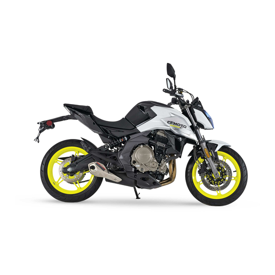
- 650NK
- Owner’s manual
-
Contents
-
Table of Contents
-
Bookmarks
Quick Links
FOREWORD
650NK
CF 6 50- 7US
OWNER’S MANUAL
GUIDE DE L’UTILISATEUR
Related Manuals for CF MOTO 650NK
Summary of Contents for CF MOTO 650NK
-
Page 1
FOREWORD 650NK CF 6 50- 7US OWNER’S MANUAL GUIDE DE L’UTILISATEUR… -
Page 2: Table Of Contents
TABLE OF CONTENTS Foreword ��������������������������������������������������������������������������������������������������������� 8 E VAP System (Evaporative Emission Control System) ������������������������������������������������9 Catalytic Converter ������������������������������������������������������������������������������������������������������10 Introduction ��������������������������������������������������������������������������������������������������13 VIN and Engine Serial Number ��������������������������������������������������������������������14 Specifications ����������������������������������������������������������������������������������������������15 Operator Safety ��������������������������������������������������������������������������������������������18 General Safety Precautions ����������������������������������������������������������������������������������������18 Owner Responsibilities ������������������������������������������������������������������������������������������������22 Safe Riding Gear ���������������������������������������������������������������������������������������������������������23 Potential Hazard Warnings ������������������������������������������������������������������������������������������26 Safety Decals and Locations �����������������������������������������������������������������������31 Vehicle View �������������������������������������������������������������������������������������������������33…
-
Page 3
Handlebar Switch, LH �������������������������������������������������������������������������������������������������36 Handlebar Switch, RH �������������������������������������������������������������������������������������������������37 Throttle Grip ����������������������������������������������������������������������������������������������������������������37 Locks ���������������������������������������������������������������������������������������������������������������������������38 Gear Shift Lever ����������������������������������������������������������������������������������������������������������40 Rear Brake Lever ��������������������������������������������������������������������������������������������������������41 Side Stand �������������������������������������������������������������������������������������������������������������������41 Passenger handhold and footrest �������������������������������������������������������������������������������42 TFT Instrument (Select markets) �����������������������������������������������������������������43 Instrument Indicators ���������������������������������������������������������������������������������������������������43 Instrument �������������������������������������������������������������������������������������������������������������������43 Activation and Test ������������������������������������������������������������������������������������������������������43 Instrument Indicators ���������������������������������������������������������������������������������������������������44 Instrument Display (ECO Mode) ���������������������������������������������������������������������������������47 Instrument Display (Sport Mode) ��������������������������������������������������������������������������������48… -
Page 4
Starting Off ������������������������������������������������������������������������������������������������������������������79 Shifting, Riding ������������������������������������������������������������������������������������������������������������79 Brake ���������������������������������������������������������������������������������������������������������������������������81 Parking ������������������������������������������������������������������������������������������������������������������������82 Safety Operation ������������������������������������������������������������������������������������������83 Safe Riding Technique ������������������������������������������������������������������������������������������������83 Additional Cautions for High Speed Operation �����������������������������������������������������������85 Maintenance �������������������������������������������������������������������������������������������������86 Severe Use Definition �������������������������������������������������������������������������������������������������86 Key Points of Lubrication Schedule: ��������������������������������������������������������������������������87 Break-in Maintenance Schedule ���������������������������������������������������������������������������������88 Periodic Maintenance Schedule ����������������������������������������������������������������������������������91 Clutch Lever Freeplay �������������������������������������������������������������������������������������������������97 Took Kit �����������������������������������������������������������������������������������������������������������������������98… -
Page 5
Engine Oil Capacity ���������������������������������������������������������������������������������������������������104 Spark Plug �����������������������������������������������������������������������������������������������������������������105 Air Intake and Exhaust System������������������������������������������������������������������106 Fuel & Exhaust Detecting System �����������������������������������������������������������������������������106 Air Intake Valve ���������������������������������������������������������������������������������������������������������106 Valve Clearance ��������������������������������������������������������������������������������������������������������107 Air Filter ���������������������������������������������������������������������������������������������������������������������108 Cooling System �������������������������������������������������������������������������������������������109 Radiator and Cooling Fan �����������������������������������������������������������������������������������������109 Radiator Hoses ���������������������������������������������������������������������������������������������������������109 Coolant ���������������������������������������������������������������������������������������������������������������������� 110 Coolant Level Inspection �������������������������������������������������������������������������������������������… -
Page 6
Front Brake Lever Inspection ������������������������������������������������������������������������������������120 Rear Brake Pedal Inspection ������������������������������������������������������������������������������������120 Brake Fluid Level Inspection �������������������������������������������������������������������������������������121 Adding Brake Fluid ����������������������������������������������������������������������������������������������������122 Brake Disc Inspection �����������������������������������������������������������������������������������������������124 Brake Caliper Inspection �������������������������������������������������������������������������������������������124 Anti-lock Braking System (ABS) ��������������������������������������������������������������������������������125 Shock Absorber ������������������������������������������������������������������������������������������126 Shock Absorber Inspection ���������������������������������������������������������������������������������������126 Shock Absorber Inspection ���������������������������������������������������������������������������������������127 Rear Shock Absorber Adjustment �����������������������������������������������������������������������������127 Electrical System and Light Signal �����������������������������������������������������������128 Battery �����������������������������������������������������������������������������������������������������������������������128… -
Page 7
Protect the Surface ���������������������������������������������������������������������������������������������������139 Windshield and Other Plastic ������������������������������������������������������������������������������������139 Chrome and Aluminum ����������������������������������������������������������������������������������������������139 Preparation for Storage ���������������������������������������������������������������������������������������������141 Preparation After Storage ������������������������������������������������������������������������������������������142 Transporting Your Vehicle �����������������������������������������������������������������������������������������142 General troubles and causes ���������������������������������������������������������������������143 Reporting Safety Defects ������������������������������������������������������������������������������������������145 Warranty Information ���������������������������������������������������������������������������������146 Change of Ownership �����������������������������������������������������������������������������������������������146 CFMOTO LIMITED WARRANTY �������������������������������������������������������������������147 Telematics BOX (T-BOX) �����������������������������������������������������������������������������154… -
Page 8: Foreword
FOREWORD Foreword Welcome Thank you for purchasing a CFMOTO vehicle, and welcome to our world-wide family of CFMOTO enthusiasts� Be sure to visit us online at www�cfmoto�com for the latest news, new product introductions, upcoming events, and more� CFMOTO is an international company that specializes in the development, manufacture, and marketing of all-terrain vehicles, utility vehicles, large displacement motorcycles, and their core components�…
-
Page 9: E Vap System (Evaporative Emission Control System)
FOREWORD Before every ride, please inspect your vehicle and follow the basic maintenance procedures before riding� Please keep this manual together with your vehicle, even when transferring the vehicle to others� Zhejiang CFMOTO POWER CO., Ltd reserves the final explanation rights of the owner’s manual. DANGER Operating, servicing and maintaining on-road or off-road vehicles can expose you to chemicals including engine exhaust, carbon monoxide, phthalates, and lead, which are known to cause cancer and birth…
-
Page 10: Catalytic Converter
FOREWORD Catalytic Converter CAUTION: Please pay attention to the following to protect your catalytic converter: • Use only unleaded gasoline� Even gasoline that contains a little lead could damage the reactive metals contained in the catalytic converter and disable it� •…
-
Page 11
FOREWORD Signal Words A signal word calls attention to a safety message or messages, a property damage message or messages, and designates a degree or level of hazard seriousness� The standard signal words in this manual are DANGER, WARNING, CAUTION and NOTE� The following signal words and symbols appear throughout this manual and on your vehicle�… -
Page 12
FOREWORD READ THE OWNER’S MANUAL FOLLOW ALL INSTRUCTIONS AND WARNINGS WARNING Read, understand, and follow all of the instructions and safety precautions in this manual and on all product labels. Failure to follow the safety precautions could result in serious injury or death. WARNING The engine exhaust gas from this product contains CO, which is deadly gas and could cause headaches, giddiness, loss of consciousness, or even death. -
Page 13: Introduction
INTRODUCTION Introduction Thank you for purchasing a CFMOTO vehicle, and welcome to our world-wide family of CFMOTO enthusiasts� For safe and enjoyable operation of your vehicle, be sure to follow the instructions and recommendations in this owner’s manual� Information about major repairs are outlined in the CFMOTO Service Manual, and should only be performed by a CFMOTO service dealer and technician�…
-
Page 14: Vin And Engine Serial Number
INTRODUCTION VIN and Engine Serial Number Be sure to record the VIN number, engine serial number and name plate information in the spaces below: Vehicle identification number: Engine serial number: 1 VIN No� 2 Engine serial No�…
-
Page 15: Specifications
SPECIFICATIONS Specifications 650-7US Performance Max� power 60�3 hp (45 kw) / 8750 rpm Max� torque 41�3 ft-lb (56 N•m) / 7000 rpm Top designed speed 105�6 mph (170 km/h) Size Length 83�2 in� (2114 mm) Width 32�7 in� (830 mm) Height 43�3 in�…
-
Page 16
SPECIFICATIONS First choice: SAE 10W-40 SJ JASO-MA2 Second choice: SAE 10W-30 SJ / SAE 10W-50 SJ / SAE 20W-40 SJ / SAE Engine oil type 20W-50 SJ JASO-MA2 Idle Speed 1450 r/min ± 150 r/min Transmission Transmission type 6-speed, manual gear shift Clutch type Wet, multi-disc, manual Driving system… -
Page 17
SPECIFICATIONS Electric components Battery 12V/9 Ah Headlight Tail / brake light Turn signals… -
Page 18: Operator Safety
OPERATOR SAFETY Operator Safety General Safety Precautions WARNING Failure to heed the warnings contained in this manual can result in serious injury or death� This vehicle is not a toy and can be hazardous to operate� Read this owner’s manual� Understand all safety warnings, precautions and operating procedures before operating this vehicle�…
-
Page 19
OPERATOR SAFETY Equipment Modifications CFMOTO is concerned with the safety of our customers and for the general public� Therefore, we strongly recommend that consumers do not install on a vehicle, any equipment that may increase the speed or power of the vehicle, or make any other modifications to the vehicle for these purposes. Any modifications to the original equipment of the vehicle create a substantial safety hazard and increase the risk of body injury�… -
Page 20
OPERATOR SAFETY Avoid Gasoline Fires and Other Hazards Gasoline is extremely flammable and highly explosive. Fuel vapors can spread and be ignited by a spark or flame many feet away from the engine. To reduce the risk of fire or explosion, follow these instructions: •… -
Page 21
OPERATOR SAFETY WARNING Gasoline is highly flammable and explosive under certain conditions. Allow the engine and exhaust system to cool before filling the tank. Always exercise extreme caution whenever handling gasoline� Always refuel with the engine stopped, and outdoors or in a well ventilated area� Do not smoke or allow open flames or sparks in or near the area where refueling is performed, or where gasoline is stored�… -
Page 22: Owner Responsibilities
OPERATOR SAFETY Owner Responsibilities Be Qualified and Responsible Read this Owner’s Manual and the warning decals on this vehicle carefully� Take a safety training course on open areas if available� Practice at low speeds� Higher speeds require greater experience, knowledge and suitable riding conditions�…
-
Page 23: Safe Riding Gear
OPERATOR SAFETY Safe Riding Gear Always wear clothing suited to the type of riding for the driver and passenger, includes: An approved helmet Eye protection� Gloves Long sleeve shirts or jackets Long pants Over-the-ankle boots According to the actual weather, you may need extra apparel, such as anti-fog eye protection, thermal underwear and a face guard for cold weather�…
-
Page 24
OPERATOR SAFETY An open-face helmet cannot offer the same protection for your face and jaw� Please wear detachable face masks and goggles when wearing an open-face helmet� Do not depend on eyeglasses or sunglasses for eye protection, as they are not rated for impact protection� Debris may fly up and or break the lens, causing eye injury. -
Page 25
OPERATOR SAFETY Boots Always wear closed-toe, over-the-ankle boots� Sturdy over-the-ankle boots with non-slip soles offer more protection, and allow you to plant your foot properly on the foot pegs� Avoid long shoelaces that could get tangled in the vehicle components� For winter riding conditions, rubber-soled boots with either nylon or leather uppers and removable felt liners are best suited�… -
Page 26: Potential Hazard Warnings
OPERATOR SAFETY Potential Hazard Warnings WARNING POTENTIAL HAZARD: Operating this vehicle without proper instruction� WHAT CAN HAPPEN: The risk of an accident is greatly increased if the operator does not know how to operate the vehicle properly in different situations and on different types of terrain� HOW TO AVOID THE HAZARD: New and inexperienced operators should complete a safety training course if offered by dealer�…
-
Page 27
OPERATOR SAFETY WARNING POTENTIAL HAZARD: Operating this vehicle without wearing approved helmet, eye protection, and protective clothing� WHAT CAN HAPPEN: Operating without an approved helmet increases the risk of a severe head injury or death in the event of an accident� Operating without eye protection could result in an accident and could increase the chance of a severe eye injury in the event of an accident�… -
Page 28
OPERATOR SAFETY WARNING POTENTIAL HAZARD: Operating at excessive speeds� WHAT CAN HAPPEN: Excessive speed increases the operator’s chance of losing control, which can result in an accident� HOW TO AVOID THE HAZARD: Always operate at a speed that’s proper for the terrain, visibility and operating conditions, and your experience�… -
Page 29
OPERATOR SAFETY WARNING POTENTIAL HAZARD: Failure to inspect the vehicle before operating� Failure to properly maintain the vehicle� WHAT CAN HAPPEN: Poor maintenance increases the possibility of an accident or equipment damage� HOW TO AVOID THE HAZARD: Always inspect your vehicle before each use to make sure it is in safe operating condition� Always follow the inspection and maintenance procedures and schedules described in the owner’s manual�… -
Page 30
OPERATOR SAFETY WARNING POTENTIAL HAZARD: Operating the vehicle with improper modifications. WHAT CAN HAPPEN: Improper installation of accessories or modification of the vehicle may cause changes in handling which could lead to an accident� HOW TO AVOID THE HAZARD: Never modify the vehicle through improper installation or use of accessories� All parts and accessories added to the vehicle must be genuine parts or equivalent components designed for use on this vehicle, and they should be installed and used according to approved instructions�… -
Page 31: Safety Decals And Locations
SAFETY DECALS AND LOCATIONS Safety Decals and Locations Read and understand all of the safety and information labels on your vehicle for safe and proper operation� Never remove any labels from your vehicle. If a label becomes difficult to read or falls off, a replacement is available from your CFMOTO dealer�…
-
Page 32
SAFETY DECALS AND LOCATIONS… -
Page 33: Vehicle View
CONTROLS & FEATURES Vehicle View Rear Left View 1: Instrument 2: Clutch lever 3: Handlebar switch, LH 4: Ignition switch lock 5: Fuel tank lock 6: Gear shift lever 7: Seat lock 8: Passenger handhold 9: Footrests…
-
Page 34: Front Right View
CONTROLS & FEATURES Front Right View 10: Throttle grip 11: Handlebar switch, RH 12: Front hand brake lever 13: Rear brake lever…
-
Page 35: Controls And Features
CONTROLS & FEATURES Controls and Features Clutch Lever Clutch lever is on the left side of handlebar� The clutch is cable-operated type� Adjust the clutch lever’s distance to the handlebar by turning the clutch lever adjusting knob� Adjusting knob Front Hand Brake Lever Front hand brake lever is on the right side of handlebar�…
-
Page 36: Handlebar Switch
CONTROLS & FEATURES Handlebar Switch, LH Left handlebar switch is on the left side of the handlebar� Function of left handlebar switch Turn to this position, high beam lights on� Dimmer push switch Turn to this position, low beam lights on� Short press to shift between Mode button MODE…
-
Page 37: Handlebar Switch
CONTROLS & FEATURES Handlebar Switch, RH Right handlebar switch is on the right side of the handlebar� Right handlebar switch function Turn to this position, the vehicle turns off� Turn to this position, the vehicle Stop switch is ready to start� Push this button to start the vehicle�…
-
Page 38: Locks
CONTROLS & FEATURES Locks Ignition switch Turn the handlebar to the left, then turn the key to the lock indicator to lock the Handlebar lock handlebar� Turn the key to this position, the engine cannot be started and the vehicle Turn off power circuit is disconnected�…
-
Page 39
CONTROLS & FEATURES Fuel Tank Lock Follow the items below before opening the fuel tank: The vehicle is stopped� Engine is off� Open the fuel tank lock cover� Insert the key and turn to release the lock� Open the fuel tank cap�… -
Page 40: Gear Shift Lever
CONTROLS & FEATURES Seat Lock The seat lock is on the left side of the vehicle� The seat can be removed by inserting the key and turning to release the lock� Gear Shift Lever The gear shift lever is on the left side of the engine�…
-
Page 41: Rear Brake Lever
CONTROLS & FEATURES Rear Brake Lever The rear brake lever is on the right side of the engine� Activate the rear brake by pushing down on the rear brake lever� Side Stand The side stand is on the left side of the vehicle, and is used for parking�…
-
Page 42: Passenger Handhold And Footrest
CONTROLS & FEATURES Passenger handhold and footrest A passenger handhold is mounted on the motorcycle seat for passenger to hold on during riding� Footrests are mounted on the motorcycle for the operator and passenger�…
-
Page 43: Tft Instrument (Select Markets)
CONTROLS & FEATURES TFT Instrument (Select markets) Instrument Indicators Instrument Instrument is located at the front of handlebar, and here are two function areas: : Instrument indicators area : Instrument display area Activation and Test Activation The instrument is activated when vehicle power is on� Test Display area shows welcome words and indicators flash in short time for self inspection�…
-
Page 44: Instrument Indicators
CONTROLS & FEATURES Instrument Indicators…
-
Page 45
CONTROLS & FEATURES Symbol Function Flash Indicator flashes when the turn light goes on. Keep on Position light indicator will be on when position light turns on� When electric circuit is connected and engine is off, EFI fault indicator will be on� If the engine is not off and the indicator is still on, it means the vehicle detects any fault, the fault will Keep on be displayed on the dashboard for warning�… -
Page 46
CONTROLS & FEATURES Fuel level indicator will be on when fuel level is very low� Please plan your trip reasonably and refuel soon� When faults are Flash / Keep on detected, the fuel level indicator will flash. Please contact your CFMOTO dealer as soon as possible�… -
Page 47: Instrument Display (Eco Mode)
CONTROLS & FEATURES Instrument Display (ECO Mode) 1 Clock 5 Coolant Temp� 9 Optional Info 2 Display 2 Speed Display 6 Fuel Level 10 Engine RPM 3 Blue Tooth 7 Optional Info 1 Display 4 Gear Position 8 Vehicle Mode…
-
Page 48: Instrument Display (Sport Mode)
CONTROLS & FEATURES Instrument Display (Sport Mode) 1 Clock 5 Coolant Temp� 9 Optional Info 2 Display 2 Speed Display 6 Fuel Level 10 Engine RPM 3 Blue Tooth 7 Optional Info 1 Display 4 Gear Position 8 Vehicle Mode…
-
Page 49
CONTROLS & FEATURES Clock Display the current time� The clock is adjustable and can be shifted between 12 hours and 24 hours through the menu� PM 10:50 22:50 Speed Display Display the current vehicle speed� Speed unit could be shifted between km/h and mph through the menu operation�… -
Page 50
CONTROLS & FEATURES Blue Tooth When cellphone is paired with the instrument, this area will display the blue tooth symbol, cellphone signal strength and cellphone battery gauge� Gear Position Display the current gear position� Neutral position is displayed in green color�… -
Page 51
OPERATING YOUR VEHICLE Coolant Temperature The coolant temperature indicator consists of bars, the more bars light up, the hotter the coolant� When the last bar lights up and the coolant temperature indicator flashes, it means the temperature is reaching the danger limit� WARNING Overheating could lead to engine damage�… -
Page 52
OPERATING YOUR VEHICLE Optional Information Customer can select two items displayed� Optional Info 1 : ODO, trip1, trip 2� Optional Info 2 : Voltage, instantaneous fuel consumption, trip 1 travel time, trip 2 travel time, total odometer travel time, trip 1 average fuel consumption, trip 2 average fuel consumption, total odometer average fuel consumption, trip 1 average speed, trip 2 average speed, total odometer average speed�… -
Page 53
OPERATING YOUR VEHICLE Engine RPM Please avoid high engine RPM during break-in period� In order to increase the engine life, please keep RPM away from the red area� Before finishing engine warm up, do not run in high engine RPM� ×1000r/min… -
Page 54: Instrument Menu
OPERATING YOUR VEHICLE Instrument Menu Adjust the instrument setting through the menu for better driving Information experience� Long press the “ENTER” button on the handlebar switch to enter into instrument menu� WARNING Instrument menu can be entered only when the vehicle is stopped and safe�…
-
Page 55
OPERATING YOUR VEHICLE Voltage and Coolant Temp. Long press “ENTER” button to enter into menu. Information Short press “” or “” to mark “Information” item, press “ENTER” button to enter into the item. Voltage and coolant temp� information is displayed in this information list�… -
Page 56
OPERATING YOUR VEHICLE Long press “ENTER” to enter into menu. Short press “” or “” to select the “Information”, Information press “ENTER” to open the select item. Short press “” or “” to select “warning”, press “ENTER” to open warning item� Warning item will display all current faults of the vehicle, so please contact CFMOTO authorized dealer to eliminate all the faults�… -
Page 57
OPERATING YOUR VEHICLE Service The vehicle has a service interval after break-in period� The Information instrument records the travel mileage and reminds the owner to do vehicle maintenance when close to 500 km to the next service time� When the time for servicing is near, the instrument will display service warning for ten seconds every time when starting the vehicle as a service reminder�… -
Page 58
OPERATING YOUR VEHICLE Miles Info The following information is recorded for trip 1, trip 2 and ODO: Information 1: Mileage Miles Info 2: Speed Version Info 3: Consumption 4: Riding time Long press “ENTER” to enter into the menu. Short press “” or “” button to select “Information” item, press “ENTER”… -
Page 59
OPERATING YOUR VEHICLE Version Info Check the current software and hardware version of the vehicle� Information Long press “ENTER” to enter into menu. Miles Info Short press “” or “” button to select “Information”, press V V e e r r s s i i o o n n I I n n f f o o “ENTER”… -
Page 60
OPERATING YOUR VEHICLE Units Shift the unit for speed, time and temperature through instrument operation� Information Long press “ENTER” button to enter into the menu� Short press“” or “” button to select “Settings”, press “ENTER” button to open setting item� Short press “”… -
Page 61
OPERATING YOUR VEHICLE Connection Pair the cellphone with bluetooth instrument, then navigation, and calling function can be used� Navigation function can be Inroemation used with CFMOTO APP� Follow the steps to pair the bluetooth: Long press “ENTER” to enter into the menu. Short press “”… -
Page 62
OPERATING YOUR VEHICLE Make sure the Bluetooth cellphone is open� Short press “” or “” button to select “Connect a new Information device”, press “ENTER” button to search devices. Devices that have been connected will be recorded in the menu� Select the device to pair directly�… -
Page 63
OPERATING YOUR VEHICLE Follow the steps to eliminate the device paired before: Long press “ENTER” to enter into the menu. Information Short press “” or “” to select “Settings”, press “ENTER” to open the setting item� Short press “” or “” to select the device connection, press “ENTER”… -
Page 64
OPERATING YOUR VEHICLE Optional Info 1 Choose one item from optional information 1 to display in the home interface� Information Long press “ENTER” to enter into the menu. Short press “” or “” button to select “Settings”, press “ENTER” button to open the setting item. Short press “”… -
Page 65
OPERATING YOUR VEHICLE Optional Info 2 Choose one item from optional information 2 to display in the Information home interface� Long press “ENTER” to enter into the menu. Short press “” or “” button to select “Settings”, press “ENTER” button to open the setting item. Short press “”… -
Page 66
OPERATING YOUR VEHICLE Brightness In addition to the automatic adjustment of brightness, instrument Information brightness can also be adjusted manually according to the menu� Long press “ENTER” to enter into the menu. Short press “” or “” button to select “Settings”, Trip 1 Reset press “ENTER”… -
Page 67
OPERATING YOUR VEHICLE Trip Reset Reset trip data manually� Information Long press “ENTER” to enter into manual. Short press “” or “” button to select “Settings”, press “ENTER” button to open the item. Short press “” or “” button to select “Trip 1 Reset” Trip 1 Reset or “Trip 2 Reset”, press “ENTER”… -
Page 68
OPERATING YOUR VEHICLE Time Settings Adjust the instrument time� Information Long press “ENTER” to enter into menu. Short press “” or “” to select “Settings”, press “ENTER” to open the item� Short press “” or “” to select “Time Settings”, press “ENTER” to open the item�… -
Page 69
OPERATING YOUR VEHICLE Language Shift the dashboard language between Chinese and English� Long press “ENTER” to enter into menu. Trip 2 Reset Information Short press “” or “” to select “Settings”, press “ENTER” button to open the item� Short press “” or “” to select “Language”, press “ENTER” button to open the item�… -
Page 70
OPERATING YOUR VEHICLE Reset All Reset all settings back to factory status� NOTICE Trip 2 Reset Information This function can not reset odometer and related function� Time Settings Long press “ENTER” to enter into the menu. Reset All Short press “” or “” button to select “Settings”, press “ENTER”… -
Page 71
OPERATING YOUR VEHICLE Navigation Pair cellphone with the instrument, turn on CFMOTO APP then Information navigation function can be used� Open the navigation in CFMOTO APP, then the instrument shifts into navigation interface automatically� Open the navigation manually: Long press “ENTER” button to enter into the manual. Short press “”… -
Page 72
OPERATING YOUR VEHICLE The instrument will display navigation interface when it activates in the cellphone� 485m Distance to the next crossroads� 18km Traffic navigation symbol Remaining distance to the 18km 18km destination� 11:00 11:00 Estimated arrival time 11:00… -
Page 73
OPERATING YOUR VEHICLE Telephone This function is available when instrument is paired with a Bluetooth cellphone� (Cellphone should connect with earphone and the instrument) Please Connect If instrument does not pair with Bluetooth cellphone, it will Bluetooth Correctly display reminding “Please Connect Bluetooth Correctly”. Please pair Bluetooth according to “Device connection”. -
Page 74
OPERATING YOUR VEHICLE “Telephone” item will record all numbers that called in during this Bluetooth connection� The records will be reset when power is off� Information Check the latest calls: Press “” or “” button to select “Telephone”, press “ENTER” button to open the item�… -
Page 75: Operating Your Vehicle
OPERATING YOUR VEHICLE Operating Your Vehicle Break-in Period The break-in period for this vehicle is the first 1000km� Maintain the vehicle according to the break-in period requirements� The following items should be observed during break-in period: 1� Do not run at high engine speeds immediately when the engine is just started� Allow the engine to warm up for 2 ~ 3 minutes at idle speed and let oil flow into all the engine lubricating parts.
-
Page 76: Daily Safety Inspection
OPERATING YOUR VEHICLE Daily Safety Inspection Checking the following items before daily riding will help keep your vehicle in safe and reliable condition� If anything appears unusual, please refer to the Maintenance and Adjustment section or contact your dealer� Do not operate the vehicle in an abnormal condition, as it may lead to serious damage or accidents� Item Content Coolant…
-
Page 77
OPERATING YOUR VEHICLE Fuel Level Check if the fuel tank volume is sufficient. Rearview Mirrors Check rearview mirrors for appropriate view angle� Light Check if all the lights work well, and if the beam height for front lights meets the local regulations�… -
Page 78: Starting
OPERATING YOUR VEHICLE Starting Sit on the vehicle with side stand up� Turn on the ignition switch� Place the transmission in Neutral� Turn the stop switch to position “ ”. Press the start button� CAUTION Engine running at high RPMs in cold temperatures negatively impacts the lifespan of engine� Always warm the engine at a low speed�…
-
Page 79: Starting Off
OPERATING YOUR VEHICLE Starting Off Pull in the clutch lever, shift the gearshift lever downward for gear 1, then slowly release the clutch lever while at the same time applying gentle throttle input� Shifting, Riding Pull in the clutch lever and release the throttle� Shift the gearshift lever upward for gears 2,3,4,5,6 (as required)�…
-
Page 80
OPERATING YOUR VEHICLE WARNING Comply with the local traffic regulations for minimum passenger age. Comply with all local traffic regulations. Ride defensively and foresightedly to detect sources of danger early on� When the tires are cold, their road grip performance is reduced� Use caution and drive with average speed for several kilometers until the tires arrive at their available temperature�… -
Page 81: Brake
OPERATING YOUR VEHICLE Brake Release the throttle when applying the brake, and use front and rear wheel brake for braking at the same time� Finish braking before turning, and shift to a lower gear according to the speed required� On long distance downhills, use the engine to compression brake and shift to lower gears, but do not allow the engine to operate with high RPM�…
-
Page 82: Parking
OPERATING YOUR VEHICLE Parking Stop the vehicle with brake� Shift the transmission to Neutral� Turn off the ignition switch� Park the vehicle on firm, level ground. Use side or middle stand (if equipped) to support vehicle� Turn the handlebar to the maximum left angle, and lock the handlebar with the key� Remove the key�…
-
Page 83: Safety Operation
SAFETY OPERATION Safety Operation Safe Riding Technique The following cautions are applicable for daily motorcycle use and should be carefully observed for safe and effective vehicle operation: • For safety, eye protection and a helmet are strongly recommended� You must be aware of safety regulations prior to riding the motorcycle�…
-
Page 84
SAFETY OPERATION • Riding at the proper speed and avoiding unnecessary acceleration are important not only for safety and low fuel consumption, but also for longer vehicle life and quieter operation� • When riding in wet conditions or on loose roadway surfaces, vehicle performance will be reduced� All of your actions should be smooth under these conditions�… -
Page 85: Additional Cautions For High Speed Operation
SAFETY OPERATION Additional Cautions for High Speed Operation Brakes: Braking is very important, especially during high speed operation� It cannot be over-forced� Check and replace pads more often to get better performance� Handling: Looseness in the handling parts may cause loss of control� Check to see whether the handlebar turns freely but has no shaking, and that the wheels turn without shaking or looseness�…
-
Page 86: Maintenance
MAINTENANCE Maintenance Careful periodic maintenance will help keep your vehicle in the safest, most reliable condition� Inspection, adjustment, and lubrication of important components are explained in the maintenance schedule� Inspect, clean, lubricate, adjust, and replace parts as necessary� When inspection reveals the need for replacement parts, always use genuine parts available from your dealer�…
-
Page 87: Key Points Of Lubrication Schedule
MAINTENANCE Key Points of Lubrication Schedule: Check all components at the intervals outlined in the Periodic Maintenance Schedule� Items not listed in the schedule should be lubricated at the general lubrication interval� • Change lubricants more often under severe use, such as wet or dusty conditions� •…
-
Page 88: Break-In Maintenance Schedule
MAINTENANCE Break-in Maintenance Schedule Break-in Maintenance Interval (Service whichever interval comes first) Item Calendar Miles Remarks Engine ■ Engine oil and oil filter 1000 Replace Idle 1000 Inspect Throttle system 1000 Drive chain and sprockets 1000 Inspect / Adjust Electrical system ■…
-
Page 89
MAINTENANCE Break-in Maintenance Interval (Service whichever interval comes first) Item Calendar Miles Remarks Wheels Tire condition 1000 Tire pressure 1000 Inspect Wheel bearings 1000 Suspension system Inspect for leaking (maintain front forks ■ Rear shock absorber and front forks 1000 and rear shock absorber according to the requirement) -
Page 90
MAINTENANCE Break-in Maintenance Interval (Service whichever interval comes first) Item Calendar Miles Remarks Other parts ■ Diagnostic connector 1000 Read with PDA Lubricate, inspect ■ Moving parts 1000 for flexibility ■ Bolts and nuts 1000 Inspect for fastness Inspect for damage, ■… -
Page 91: Periodic Maintenance Schedule
MAINTENANCE Periodic Maintenance Schedule Periodic Maintenance Interval (Service whichever interval comes first) Item Calendar Miles Remarks Engine Engine oil and oil filter 3000 5000 Replace Oil strainer 3000 5000 Clean ■ Clutch 3000 5000 Inspect Idle 6000 10000 ■ Coolant 18000 30000 Replace…
-
Page 92
MAINTENANCE Periodic Maintenance Interval (Service whichever interval comes first) Item Calendar Miles Remarks Electrical system ■ Functions of electrical parts 6000 10000 Battery 3000 5000 Inspect Fuses or circuit breakers 3000 5000 Inspect for damage, ■ Wires 6000 10000 bending and routing Wheels 6000 10000… -
Page 93
MAINTENANCE Periodic Maintenance Interval (Service whichever interval comes first) Item Calendar Miles Remarks Brake system 6000 10000 Front and rear brake system 12000 20000 6000 10000 Brake discs 12000 20000 Inspect 6000 10000 ► Brake pads 12000 20000 6000 10000 Brake fluid level 12000 20000… -
Page 94
MAINTENANCE Periodic Maintenance Interval (Service whichever interval comes first) Item Calendar Miles Remarks Suspension system ■ Suspension system 3000 5000 Inspect Inspect for leaking 6000 10000 (maintain the parts ■ Rear shock absorber and front forks according to the 12000 20000 requirement) 6000… -
Page 95
MAINTENANCE Periodic Maintenance Interval (Service whichever interval comes first) Item Calendar Miles Remarks Frame system Frame 18000 30000 Inspect Steering system 6000 10000 ■ Steering bearings Inspect 12000 20000 Chain 6000 10000 Chain, rear sprocket and engine ► Inspect sprocket 12000 20000 ►… -
Page 96
MAINTENANCE Periodic Maintenance Interval (Service whichever interval comes first) Item Calendar Miles Remarks Other parts 6000 10000 ■ Diagnosis connector Read with PDA 12000 20000 6000 10000 Lubricate; inspect ■ Mobile parts for flexibility 18000 30000 6000 10000 ■ Bolts and nuts Inspect for fastness 18000 30000… -
Page 97: Clutch Lever Freeplay
MAINTENANCE Clutch Lever Freeplay Check clutch lever smoothness� Turn handlebar towards the left to the end� Slowly pull the clutch lever until the resistance is evident� Check clutch lever position where the clearance is for freeplay: Free play: 0.2 in. ~ 0.6 in. (5 mm ~ 15 mm) WARNING If there is no free play for clutch lever, the clutch will start to slip�…
-
Page 98: Took Kit
MAINTENANCE Took Kit Tool Kit is located under the seat� The tools supplied with the vehicle are helpful for partial maintenance, disassembling and assembling�…
-
Page 99: Fuel System
MAINTENANCE Fuel System Fuel Tank Avoid spilling gasoline on the fuel tank when refueling� If a spill occurs, wipe it off immediately to avoid pollution or causing danger� Fuel tank volume:4�5 gal ± 0�13 gal (17 ± 0�5 L) DANGER Gasoline is extremely flammable and can be explosive under certain conditions.
-
Page 100: Fuel Requirement
MAINTENANCE Fuel Requirement For this motorcycle, it is recommended to use only unleaded premium gasoline� CAUTION Do not use leaded gasoline, as it will destroy the catalytic converter� (For further understanding, please refer to more information related to the catalytic converter) Be sure to use fresh gasoline�…
-
Page 101: Engine Assy
MAINTENANCE Engine Assy For the engine, transmission, and clutch to work properly, maintain the engine oil between the upper and lower lines on the oil window� During the engine lubrication process, oil not only builds up carbon by- product and metallic impurities, but may also consume itself by a small amount� Inspect and change the oil in accordance with the Periodic Maintenance Chart�…
-
Page 102: Change Engine Oil And Oil Filter
MAINTENANCE Change Engine Oil and Oil Filter Park the vehicle by side stand on level ground� Idle the engine for several minutes to warm up the oil, then shut off the engine� Allow 2 to 3 minutes for the oil to settle� WARNING Warming up the engine for a long period may lead to high temperature of the engine and engine oil�…
-
Page 103
MAINTENANCE Remove oil filter � Apply a small amount of clean oil to the rubber seal ring of the new oil filter. Install the new oil filter� CAUTION Before mounting the oil filter, applying a thin layer of oil on the seal ring prevents the filter from becoming stuck on the engine case�… -
Page 104: Engine Oil Capacity
MAINTENANCE Remove the oil filling screw plug � Fill with 2�32 qt (2�2 L) oil� Remount the oil filling screw plug. Start and idle the engine for several minutes, allowing the oil to flow into the oil filter while checking for leaks. Turn off the engine�…
-
Page 105: Spark Plug
MAINTENANCE Spark Plug The spark plugs should be replaced in accordance with the Periodic Maintenance Chart� Spark plug maintenance should only be performed by an authorized dealer� Spark plug type: CR8EI Spark plug clearance : 0�027 in� ~ 0�035 in� (0�7 mm~0�9 Tightening torque: 15 N•m…
-
Page 106: Air Intake And Exhaust System
MAINTENANCE Air Intake and Exhaust System Fuel & Exhaust Detecting System Fuel & exhaust system optimization is detected by oxygen sensor � An oxygen sensor installed on each exhaust pipe detects air & fuel combustion conditions by measuring oxygen density and transferring it as an electrical signal to the ECU� If the ECU determines that combustion is not optimal, it will make adjustments to fuel injection in accordance with signals from the TPS and Intake Air Temperature sensors�…
-
Page 107: Valve Clearance
MAINTENANCE Valve Clearance The engine valves and valve seats wear during operation� Adjustment of the valvetrain components should be performed by a dealer technician in accordance with the Periodic Maintenance Chart� WARNING If adjustment of the valve clearance is not performed, it will eventually result in no clearance or cause the valves to remain partly open, which reduces performance, creates valve noise, and can cause serious engine damage�…
-
Page 108: Air Filter
MAINTENANCE Air Filter A clogged air filter restricts air flow, increases fuel consumption, reduces engine power, and causes spark plug fouling� The air filter element must be cleaned in accordance with the periodic Maintenance Chart� When driving in dusty, rainy, or muddy conditions, the air filter element should be serviced more frequently than the recommended interval in the periodic Maintenance Chart.
-
Page 109: Cooling System
MAINTENANCE Cooling System Radiator and Cooling Fan Check the radiator fins for bending, out of shape, obstruction by insects or mud, and clear off any obstructions with a stream of low pressure water� WARNING Keep your hands and clothing away from the fan blades when it is working to avoid any injury� Using high-pressure water to wash the vehicle could damage the radiator fins and impair the radiator’s effectiveness�…
-
Page 110: Coolant
MAINTENANCE Coolant Coolant absorbs excessive heat from the engine and transfers it to the air by the radiator� If the coolant level is low, the engine will overheat and may suffer severe damage� Check the coolant level daily before riding the motorcycle and perform maintenance in accordance with the periodic maintenance chart� Replenish coolant if the level is low�…
-
Page 111
MAINTENANCE DANGER Coolant is toxic and harmful for health� Do not allow the coolant to touch skin, eyes or clothing� If coolant is swallowed, see a doctor immediately� If coolant contacts the skin, flush the contact position with plenty of water immediately. If coolant contacts the eyes, flush the eyes with plenty of water and see a doctor immediately. -
Page 112: Coolant Level Inspection
MAINTENANCE Coolant Level Inspection Park the vehicle by side stand on level ground� Inspect the coolant level in the reservoir� If it is located at area ‘B’: The coolant at the proper level� If the level is at area ‘A’: Drain out the redundant coolant until it reaches area ‘B’�…
-
Page 113: Coolant Filling
MAINTENANCE Coolant Filling Open the reservoir cover and add coolant to area B� CAUTION If coolant needs to be added frequently, or the reservoir tank is completely dry, there is probably a leak in the system� Have the cooling system inspected by an authorized dealer� Contact your dealer for replacing coolant�…
-
Page 114: Tire And Chain
MAINTENANCE Tire and Chain This vehicle only uses tubeless tires, rims and inflating valves. Only use the recommended standard tires, rims and inflating valves. Do not install inner tube tires on tubeless rims. Do not install a inner tube inside a tubeless tire�…
-
Page 115: Tire Payload
MAINTENANCE NOTE: Inspect the tire pressure when the tires are cold� Tire pressure is affected by the change of environment temperature and altitude� If the environment temperature and altitude experience a big change during the driving trip, tire pressure should be adjusted and inspected accordingly�…
-
Page 116: Tire Friction
MAINTENANCE Tire Friction When tire tread wear exceeds the use limit, the tire becomes more susceptible to punctures and failure� An accepted estimate is that 90% of all tire failures occur during the last 10% of tread life, so it is unsafe to continue to use tires until they are bald�…
-
Page 117: Drive Chain Inspection
MAINTENANCE Drive Chain Inspection The drive chain slack and lubrication must be checked daily before riding in accordance with the Periodic Maintenance Chart for safety and preventing excessive wear� If the chain becomes badly worn or maladjusted, it will lead to excessive component wear and possible failure� If the chain is too tight, it will accelerate the wear for chain, sprocket, rear sprocket and rear rim�…
-
Page 118: Chain Tension Adjustment
MAINTENANCE Chain tension inspection Place the transmission into Neutral gear� Park with the side stand on level ground� Push up the middle of the chain until it stops, and measure the distance of chain movement� If the chain tension is out of specification, adjust it to the standard�…
-
Page 119
MAINTENANCE Wear inspection Place the transmission into Neutral gear� 12�6 in� Support the vehicle with side stand� Apply chain tensioning or hanging a 22 lb� (10 kg) object on the chain� Measure the length between 20 links for elongation� If the measured length exceeds the standard limit, replace the chain with a new one�… -
Page 120: Brake System
MAINTENANCE Brake System In order to guarantee excellent performance of your vehicle and personal safety, please repair and maintain the vehicle according to the Periodic Maintenance Chart� Make sure all the parts of the brake system are in good state� If any damage occurs to the brake system, have your vehicle inspected by an authorized dealer�…
-
Page 121: Brake Fluid Level Inspection
MAINTENANCE Brake Fluid Level Inspection Park the vehicle with side stand� Inspect the front and rear brake reservoir fluid levels. If the brake fluid level is located at area ‘B’: The fluid is in proper level. If the brake fluid level is located at area ‘A’: Drain out the redundant fluid until it arrives at area ‘B’. If the brake fluid level is located at area ‘C’…
-
Page 122: Adding Brake Fluid
MAINTENANCE Adding Brake Fluid WARNING Brake fluid causes skin irritation. Rinse the affected area with plenty of water in the event of contact with the skin� Keep brake fluid out of the reach of children. Keep brake fluid away from skin, eyes or clothing. Wear protective clothing and goggles when required. Consult a doctor immediately if brake fluid has been swallowed.
-
Page 123
MAINTENANCE Front brake fluid reservoir Remove screws � Remove the cover and reservoir gasket � Refill brake fluid to area ‘B’. Reinstall the cover and reservoir gasket� Install the screws� Rear brake fluid reservoir Remove screws � Remove the cover and reservoir gasket �… -
Page 124: Brake Disc Inspection
MAINTENANCE Brake Disc Inspection Inspect brake discs periodically for any damage, out of shape, cracks or wear� Damaged brake discs may cause braking failure� Worn-out brake discs reduce the braking distance� If brake discs are damaged or exceed the wear limit, contact an authorized dealer to replace with new brake discs immediately�…
-
Page 125: Anti-Lock Braking System (Abs)
MAINTENANCE Anti-lock Braking System (ABS) ABS is a safety system that prevents locking of the wheels when driving straight ahead without the influence of lateral forces. With the assistance of ABS, when fully braking or braking in gritty, ponding, sliding or other low adhesive force road conditions, all can be handled with full brake force and will not lock the wheel which could be dangerous�…
-
Page 126: Shock Absorber
MAINTENANCE Shock Absorber Shock Absorber Inspection Holding the handle bar and front brake, compress the front fork several times to inspect for smooth function� Visually inspect the front shock absorbers for oil leaks, scratches or friction noise� After riding, check the front shocks for any mud, dirt or debris� Clean these surfaces periodically� Failure to maintain them could lead to oil seal damage and shock oil leak�…
-
Page 127: Shock Absorber Inspection
MAINTENANCE Shock Absorber Inspection Holding the handlebar, compress the front fork several times to inspect if it works smoothly� Visually inspect front shock absorber for oil leak, scratches or friction noise� After riding, check the front shock absorber if any mud on it, clean it or could lead to oil seal damage and absorber oil leak�…
-
Page 128: Electrical System And Light Signal
MAINTENANCE Electrical System and Light Signal Battery The battery in this vehicle is a maintenance-free battery� Therefore, it is unnecessary to inspect the amount of battery electrolyte or add distilled water� To ensure optimum service life of the battery, keep the battery charged properly to ensure the battery has reserve capacity available at the starter motor�…
-
Page 129
MAINTENANCE Battery Maintenance Always keep the battery fully charged, or may it damage the battery and result in a shorter life� If the vehicle is driven infrequently, inspect the Battery voltage weekly with a voltmeter� If it drops below 12�8 volts, the battery should be charged with an appropriate charger (check with your dealer)� If you will not use the vehicle for longer than 2 weeks, the battery should be tended with an appropriate trickle charger�… -
Page 130
MAINTENANCE Battery Disassembly Put the vehicle on the level ground and park� Turn off the engine and the vehicle power� Insert the key into the seat lock� Remove the seat � Remove the black negative wire (-)� Remove the red positive wire (+)� Remove battery belt �… -
Page 131
MAINTENANCE Battery maintenance Apply a mixture of baking soda and water with a soft brush to clean the battery top and terminals� Clean away dirt and any corrosion on positive and negative wire terminals with a stiff brush� A special battery charger (constant low voltage/ampere) is required for recharging low-maintenance batteries�… -
Page 132
MAINTENANCE Battery Assembly Put the vehicle on the level ground and park� Make sure the key is on “OFF” position. Mount the battery in place� Mount the red positive wire(+)� Mount the black negative wire(-)� Mount the seat� WARNING Avoid contact with skin, eyes or clothing, and always shield eyes when working near batteries� Keep out of reach of children. -
Page 133: Light
MAINTENANCE Light High beam and low beam light is adjustable� Rotate the light adjusting knob to adjust light� CAUTION Adjustment of high/low beams should be accordance with local regulations� The light ray standard is based on front and rear wheels touching down on the ground and driver sitting on the vehicle� All the lights are LED structure, which cannot be repaired if damaged or failed�…
-
Page 134: Fuse
MAINTENANCE Fuse Fuse box is located under the seat, it is visible after removing the seat and the dust cover� If a fuse is blown, inspect the electrical system for damage and replace with the same new fuse� WARNING Do not use any substitute for the standard fuse� Replace a blown fuse with a new one of the same ampere�…
-
Page 135: Catalytic Converter
MAINTENANCE Catalytic Converter This motorcycle is equipped with a catalytic converter in the exhaust system� Platinum and rhodium contained inside the converter reacts with the engine exhaust of carbon monoxide and hydrocarbons to convert them into carbon dioxide and water, resulting in cleaner exhaust gases discharged into the atmosphere�…
-
Page 136: Fuel Evaporation System
MAINTENANCE Fuel Evaporation System This vehicle is equipped with an EVAP System� Fuel vapors from the fuel tank are drawn into a carbon tank through an absorption tube� The fuel vapors are absorbed by canister that contains active carbon when the engine is stopped. When the engine is running, fuel vapors absorbed in the carbon canister flow into the air intake and burn as a normal part of combustion, avoiding environmental pollution instead of being released into the air directly�…
-
Page 137: Motorcycle Cleaning And Storage
CLEANING & STORAGE Motorcycle cleaning and storage General Precautions Keeping your motorcycle clean and in best performance will extend the vehicle service life� Covering your motorcycle with a high quality, breathable motorcycle cover will help to protect the vehicle during storage� •…
-
Page 138: Washing Vehicle
CLEANING & STORAGE Washing Vehicle • Rinse with cold water to remove any loose dirt� • Mix a mild detergent specific for motorcycles or automobiles with water in bucket. Use a soft cloth or sponge to wash your motorcycle� If necessary, use a mild degreaser to remove any oil or grease build-up�…
-
Page 139: Protect The Surface
CLEANING & STORAGE Protect the Surface After washing your motorcycle, coat the painted surfaces, both metal and plastic, with a commercially available motorcycle/automobile wax� Wax should be applied every three months or as conditions require� Always use non-abrasive products and apply them according to the instructions� Windshield and Other Plastic After washing, use a soft cloth to gently dry off plastic parts�…
-
Page 140
CLEANING & STORAGE DANGER Special care must be taken when treating tires, that rubber protective agent applied will not affect the tire tread function� If not applied correctly, it may decrease the traction between the tire and ground, possibly causing a loss of control�… -
Page 141: Preparation For Storage
CLEANING & STORAGE Preparation for Storage Clean the entire vehicle thoroughly� Run the engine for about 5 minutes, stop the engine, then change the engine oil and filter. DANGER Motorcycle oil is a toxic substance� Dispose of used oil properly� Keep the used oil out of reach of children�…
-
Page 142: Preparation After Storage
CLEANING & STORAGE Tie plastic bags over the muffler exhaust pipe to prevent moisture from entering. Put a cover over the motorcycle to keep dust and dirt from collecting on it� Preparation After Storage Remove the plastic bags from the Muffler. Verify the battery condition�…
-
Page 143: General Troubles And Causes
CLEANING & STORAGE General troubles and causes Problem Components Possible cause Solution No fuel in fuel tank Refuel Fuel System Pump blockage or damage: poor fuel quality Clean or replace Spark plug failure: excessive carbon deposits, too long Clean or replace time usage Spark plug cap failure: Poor contact or burning Clean or replace…
-
Page 144
CLEANING & STORAGE Intake and exhaust valves, piston excessive carbon Repair or Valve and piston deposits: poor fuel quality and poor oil quality replace Clutch Clutch slips: poor oil, too long time use and overloaded Adjust or replace C y l i n d e r a n d Cylinder, piston rings wear: poor oil quality and too Replace oil Insufficient… -
Page 145: Reporting Safety Defects
CLEANING & STORAGE No electricity Recharge or Battery replace Horn not Left switch Horn button fault or damage Adjust or replace working Cable Poor connection Adjust or repair Horn Horn damage Adjust or replace The items listed are the common faults of a motorcycle� If your motorcycle has failed (especially the electronic fuel injection system, fuel evaporation system, or alarms system), please contact a CFMOTO authorized dealer to check and repair the vehicle�…
-
Page 146: Warranty Information
CFMOTO LIMITED WARRANTY FOR USA Warranty Information Change of Ownership If you sell your vehicle, any valid remainder of the warranty can be transferred to the new owner� Please record the details of the exchange below and inform an authorized CFMOTO dealer: Change of Original Purchaser 2nd Owner…
-
Page 147: Cfmoto Limited Warranty
CFMOTO LIMITED WARRANTY FOR USA CFMOTO LIMITED WARRANTY Dear Customer: Thank you for purchasing a CFMOTO product� If any component on your vehicle is found to be defective in materials or workmanship within the terms and conditions of this CFMOTO Motorcycle Limited Warranty, the defective component will be repaired or replaced (at the option of CFMOTO) without charge for parts and/or labor at any authorized dealer located within the country of purchase�…
-
Page 148
CFMOTO LIMITED WARRANTY FOR USA 3. EXCLUSIONS FROM WARRANTY COVERAGE: This Warranty excludes damages or failures resulting from the following acts or circumstances: • Fire • Collision • Theft • Unavoidable natural disasters • Improper storage or transportation • Failure or negligence in the performance of periodic vehicle maintenance •… -
Page 149
CFMOTO LIMITED WARRANTY FOR USA 4. OWNER’S RESPONSIBILITIES: The vehicle’s owner must properly use, maintain, and care for the vehicle as outlined in the CFMOTO Owner’s Manual� Any warranty repairs must be performed exclusively by CFMOTO authorized Dealers� Any warranty work performed by anyone other than an authorized CFMOTO Dealer will not be covered under the CFMOTO Limited Warranty policy�… -
Page 150
CFMOTO LIMITED WARRANTY FOR USA 7. Noise Control System and Tampering: Federal law prohibits any of the following acts or causing thereof: a) The removal or rendering inoperative by any person other than for purposes of maintenance, repair, or replacement, of any device or element of design incorporated into any new vehicle for the purpose of noise control prior to its sale or delivery to the ultimate purchaser or while it is in use�… -
Page 151
CFMOTO LIMITED WARRANTY FOR USA Emissions Warranty Period: CFMOTO warrants that each new 2020 and later CFMOTO motorcycle that includes as standard equipment a headlight, taillight, stoplight and is street-legal, is free from defects in material and workmanship which cause such motorcycle to fail to conform with applicable regulations of the United States Environmental Protection Agency or the California Air Resources Board for a period of use of five (5) Years or 30,000km (18,641 miles), whichever occurs first for 300cc or above motorcycles, and a period of use of five (5) Years or 12,000 km (7456 miles), whichever comes first for 125cc motorcycles. -
Page 152
CFMOTO LIMITED WARRANTY FOR USA III. The following parts are considered emission-related components for evaporative emissions (If applicable): 1� Fuel Tank 7� Control Valves* 13� Purge Valves 2� Fuel Cap 8� Control Solenoids* 14� Vapor Hoses 3� Fuel Line 9� Electronic Controls* 15�… -
Page 153
CFMOTO LIMITED WARRANTY FOR USA 10. INTEGRATION: This limited warranty supersedes any and all oral, express, or written warranties, statements, or undertakings that may previously have been made, and contains the entire agreement of the parties with respect to the warranty of CFMOTO vehicles� Any and all warranties not contained in this Agreement are specifically excluded�… -
Page 154: Telematics Box (T-Box)
Telematics BOX (T-BOX) CFMOTO vehicles are equipped with an intelligent vehicle terminal T-Box� It build the communication bridge between the owner and vehicle through CFMOTO APP� Please search and download CFMOTO APP�…
-
Page 155
TABLE DES MATIÈRES Avant-propos ����������������������������������������������������������������������������������������������161 Bi envenue����������������������������������������������������������������������������������������������������������������������161 Système EVAP (Système de recyclage des vapeurs de carburant) �������������������������162 Convertisseur catalytique ������������������������������������������������������������������������������������������163 Introduction ������������������������������������������������������������������������������������������������166 Numéros d’identification du véhicule (VIN) et numéro de série du moteur �������������������167 Spécifications ��������������������������������������������������������������������������������������������168 Sécurité de l’utilisateur �����������������������������������������������������������������������������171 Mesures de sécurité… -
Page 156
Levier de frein avant ��������������������������������������������������������������������������������������������������188 Commutateur de guidon, côté gauche ����������������������������������������������������������������������189 Commutateur de guidon, côté droit ���������������������������������������������������������������������������190 Poignées d’accélérateur ��������������������������������������������������������������������������������������������191 Verrouillages �������������������������������������������������������������������������������������������������������������191 Sélecteur de vitesse ��������������������������������������������������������������������������������������������������193 Pédale de frein arrière �����������������������������������������������������������������������������������������������194 Béquille ���������������������������������������������������������������������������������������������������������������������194 Poignée de retenue et repose-pieds passager ���������������������������������������������������������195 Écran TFT (dans certains pays) �����������������������������������������������������������������196 Instrumentation d’affichage ���������������������������������������������������������������������������������������196 Activation et essai �����������������������������������������������������������������������������������������������������196… -
Page 157
Démarrage de la moto ����������������������������������������������������������������������������������������������233 Passage des vitesses et conduite �����������������������������������������������������������������������������233 Freinage ��������������������������������������������������������������������������������������������������������������������235 Stationnement �����������������������������������������������������������������������������������������������������������236 Conduite du véhicule en toute sécurité ����������������������������������������������������237 Technique de conduite du véhicule en toute sécurité �����������������������������������������������237 Précautions supplémentaires pour la conduite à grande vitesse ������������������������������239 Entretien �����������������������������������������������������������������������������������������������������240 Définition d’utilisation abusive �����������������������������������������������������������������������������������240 Points clés du calendrier durant la période de rodage ����������������������������������������������241… -
Page 158
Bougie d’allumage �����������������������������������������������������������������������������������������������������259 Système d’admission d’air et d’échappement ������������������������������������������260 Système de détection du carburant et d’échappement ���������������������������������������������260 Valve d’admission d’air ����������������������������������������������������������������������������������������������261 Jeu des soupapes �����������������������������������������������������������������������������������������������������261 Filtre à air ������������������������������������������������������������������������������������������������������������������262 Système de refroidissement ����������������������������������������������������������������������263 Radiateur et ventilateur ���������������������������������������������������������������������������������������������263 Durites et radiateur ����������������������������������������������������������������������������������������������������263 Liquide de refroidissement ����������������������������������������������������������������������������������������264 Vérification du niveau de liquide de refroidissement �������������������������������������������������266 Remplissage deliquide de refroidissement ���������������������������������������������������������������267… -
Page 159
Système de freinage�����������������������������������������������������������������������������������274 Vérification du levier de frein avant ���������������������������������������������������������������������������274 Vérification du levier de frein arrière �������������������������������������������������������������������������274 Vérification du niveau de liquide des freins ���������������������������������������������������������������275 Remplissage de liquide de frein ��������������������������������������������������������������������������������276 Vérification des disques de frein �������������������������������������������������������������������������������278 Vérification des étriers de frein ���������������������������������������������������������������������������������278 Système de freinage antiblocage (ABS) �������������������������������������������������������������������279 Amortisseurs ����������������������������������������������������������������������������������������������280 Vérification des amortisseurs ������������������������������������������������������������������������������������280… -
Page 160
Nettoyage et remisage de la moto�������������������������������������������������������������291 Précautions générales ����������������������������������������������������������������������������������������������291 Lavage de la moto �����������������������������������������������������������������������������������������������������292 Protection de la surface ��������������������������������������������������������������������������������������������293 Pare-brise et autres pièces en plastique �������������������������������������������������������������������293 Chrome et aluminium ������������������������������������������������������������������������������������������������293 Préparation pour le remisage ������������������������������������������������������������������������������������295 Préparation après le remisage ����������������������������������������������������������������������������������296 Transport du véhicule ������������������������������������������������������������������������������������������������296 Diagnostic du véhicule ������������������������������������������������������������������������������297 Problèmes généraux et causes possibles �������������������������������������������������298… -
Page 161: Avant-Propos
AVANT-PROPOS Bienvenue Nous vous félicitons pour votre achat d’un véhicule CFMOTO et vous souhaitons la bienvenue dans la grande famille des passionnés de CFMOTO. Assurez-vous de nous visiter en ligne sur www.cfmoto.com pour connaître les dernières nouvelles, les lancements de nouveaux produits, les futurs événements, et plus encore� CFMOTO est une entreprise internationale qui se spécialise dans le développement, la fabrication et la commercialisation de véhicules tout-terrain, de véhicules utilitaires, de motocyclettes grosses cylindrées et de leurs principales pièces�…
-
Page 162: Système Evap (Système De Recyclage Des Vapeurs De Carburant)
AVANT-PROPOS Avant chaque sortie, veuillez inspecter votre véhicule et suivre les procédures d’entretien de base avant la conduite� Veuillez conserver ce manuel dans votre véhicule, même lorsque vous transférez le véhicule à un autre propriétaire� Zhejiang CFMOTO Power Co�, Ltd se réserve les droits d’interprétation définitifs du manuel du propriétaire�…
-
Page 163: Convertisseur Catalytique
AVANT-PROPOS Convertisseur catalytique ATTENTION: Veuillez porter attention aux points suivants pour protéger votre convertisseur catalytique : • Utilisez seulement de l’essence sans plomb� Une essence qui contient même un peu de plomb pourrait endommager les métaux réactifs dans le convertisseur catalytique et le désactiver� •…
-
Page 164
AVANT-PROPOS Mentions d’avertissement Une mention d’avertissement vise à attirer l’attention sur un ou plusieurs messages relatifs à la sécurité, sur un ou plusieurs messages relatifs à des dommages matériels, et désigne le degré ou niveau de gravité du risque� Les mentions d’avertissement standard dans ce manuel sont : DANGER, AVERTISSEMENT, ATTENTION et REMARQUE�… -
Page 165
AVANT-PROPOS LISEZ ATTENTIVEMENT LE MANUEL DU PROPRIÉTAIRE CONFORMEZ-VOUS AUX INSTRUCTIONS ET AUX AVERTISSEMENTS AVERTISSEMENT Lisez, comprenez et conformez-vous à toutes les instructions et mesures de sécurité décrites dans ce manuel et indiquées sur tous les autocollants apposés sur le véhicule. Tout manquement aux mesures de sécurité… -
Page 166: Introduction
INTRODUCTION Merci d’avoir choisi un véhicule CFMOTO et bienvenue au sein de notre famille mondiale des passionnés de CFMOTO� Pour une utilisation optimale et sans danger de votre véhicule, veuillez lire attentivement et respecter les instructions et recommandations contenues dans ce Manuel du propriétaire� Des informations sur les réparations importantes sont décrites dans le Manuel d’entretien de CFMOTO�…
-
Page 167: Numéros D’identification Du Véhicule (Vin) Et Numéro De Série Du Moteur
INTRODUCTION Numéros d’identification du véhicule (VIN) et numéro de série du moteur Notez le numéro d’identification du véhicule et le numéro de série du moteur ci-dessous. Numéro d’identification du véhicule (VIN) : Numéro de série du moteur : de VIN 2 Numéro de série du moteur…
-
Page 168: Spécifications
SPÉCIFICATIONS 650-7US Performance Puissance maximale 60,3 Hp (45 kw) / 8750 tr/min Couple maximal 41,3 pi-lb (56 N•m) / 7000 tr/min Vitesse nimaine 105,6 mi/h (170 km/h) Taille Longueur 83,2 po (2114 mm) Largeur 32,7 po (830 mm) Hauteur 43,3 po (1100 mm) Empattement 55,7 po (1415 mm) Garde au sol…
-
Page 169
SPÉCIFICATIONS Premier choix : SAE 10W-40 SJ JASO-MA2 Type d’huile moteur Deuxième choix : SAE 10W-30 SJ / SAE 10W-50 SJ / SAE 20W-40 SJ / SAE 20W-50 SJ JASO-MA2 Régime ralenti 1450 tr/min ± 150 tr/min Transmission Type de transmission 6 vitesses, sélecteur de vitesse Type d’embrayage À… -
Page 170
SPÉCIFICATIONS Composants électrique Batterie 12V/9 Ah Phares Feu arrière / Feu de freinage Feu clignotant… -
Page 171: Sécurité De L’utilisateur
SÉCURITÉ DE L’UTILISATEUR Mesure de sécurité générales AVERTISSEMENT Tout non-respect des avertissements contenus dans ce manuel peut entraîner des blessures graves, voire mortelles� Ce véhicule n’est pas un jouet et son utilisation présente des dangers� Avant d’utiliser le véhicule, lisez attentivement ce Manuel du propriétaire et comprenez tous les avertissements et les précautions liés à…
-
Page 172
La garantie de votre véhicule CF MOTO devient nulle si un quelconque équipement accessoire non approuvé est ajouté au véhicule, ou si une quelconque modification est faite sur le véhicule aux fins d’en augmenter la puissance ou la vitesse�… -
Page 173
SÉCURITÉ DE L’UTILISATEUR Évitez les incendies et autres risques causés par l’essence L’essence est extrêmement inflammable et ses vapeurs hautement explosives. Des vapeurs d’essence peuvent s’étendre et s’embraser en présence d’une étincelle ou d’une flamme même à plusieurs pieds du moteur� Pour réduire le risque d’incendie ou d’explosion, suivez ces instructions� Respectez rigoureusement les procédures de remplissage appropriées�… -
Page 174
SÉCURITÉ DE L’UTILISATEUR AVERTISSMENT • L’essence est très inflammable et explosive dans certaines conditions. • Laissez le moteur et le pot d’échappement se refroidir avant de remplir le réservoir� • Redoublez toujours de prudence toutes les fois que vous manipulez de l’essence� •… -
Page 175: Responsabilités Du Propriétaire
SÉCURITÉ DE L’UTILISATEUR Responsabilités du propriétaire Soyez qualifié et responsable Lisez très attentivement ce Manuel du propriétaire et comprenez les autocollants d’avertissement sur ce véhicule� Suivez, si disponible, un cours de formation sur la conduite sécuritaire en terrain découvert� Entraînez-vous à conduire à de basses vitesses pour commencer. Les vitesses plus élevées exigent une expérience et des connaissances plus grandes, ainsi que des conditions de conduite appropriées�…
-
Page 176: Équipement De Sécurité Pour La Conduite
SÉCURITÉ DE L’UTILISATEUR Équipement de sécurité pour la conduite Le pilote et le passager doivent toujours porter des vêtements et équipements adaptés au type de conduite afin de réduire les risques de blessures� Ceci comprend : Un casque de protection approuvé Une protection oculaire Des gants Un chandail à…
-
Page 177
SÉCURITÉ DE L’UTILISATEUR dans votre pays ou région� Un casque intégral avec écran facial reste ce qu’il y a de mieux pour se protéger des impacts d’insectes, des projections de petits cailloux, de la poussière, des débris volants, etc�Un casque ouvert n’est pas en mesure d’offrir la même protection pour votre visage et vos mâchoires�… -
Page 178
SÉCURITÉ DE L’UTILISATEUR vêtements de protection adéquats comme une veste coupe-vent et des habits à couches isolées sont essentiels� Même lorsque vous conduisez à des températures modérées, vous pourrez ressentir un froid intense à cause du vent� Par contre, des vêtements de protection appropriés pour la conduite par temps froid peuvent s’avérer trop chauds dès que vous vous arrêtez�… -
Page 179: Avertissements De Danger Potentiel
SÉCURITÉ DE L’UTILISATEUR Avertissements de danger potentiel AVERTISSEMENT DANGER POTENTIEL : Non-respect des instructions de conduite appropriées de ce véhicule� CONSÉQUENCES POSSIBLES : Le risque d’accident augmente de façon considérable si l’utilisateur ne maîtrise pas correctement son véhicule dans tous les types de situations et sur différents types de terrain� COMMENT ÉVITER LE DANGER: Les utilisateurs débutants et inexpérimentés doivent suivre un cours de formation sur la sécurité…
-
Page 180
SÉCURITÉ DE L’UTILISATEUR AVERTISSEMENT DANGER POTENTIEL : Conduire ce véhicule sans casque homologué, protection oculaire et vêtements de protection� CONSÉQUENCES POSSIBLES : Conduire sans casque homologué augmente le risque de blessures graves à la tête ou même la mort en cas d’accident� Conduire sans protection oculaire peut provoquer un accident et augmenter le risque de graves blessures aux yeux en cas d’accident�… -
Page 181
SÉCURITÉ DE L’UTILISATEUR AVERTISSEMENT DANGER POTENTIEL : Conduire à des vitesses excessives� CONSÉQUENCES POSSIBLES : Une vitesse excessive augmente le risque de perte de contrôle du véhicule par le conducteur, pouvant ainsi provoquer un accident� COMMENT ÉVITER LE DANGER: Conduisez toujours à une vitesse adaptée au terrain, à la visibilité, aux conditions ambiantes et à votre expérience�… -
Page 182
SÉCURITÉ DE L’UTILISATEUR AVERTISSEMENT DANGER POTENTIEL : Non-respect des vérifications d’usage avant l’utilisation et/ou l’entretien non conforme de ce véhicule. CONSÉQUENCES POSSIBLES : Un mauvais entretien augmente le risque d’accident ou de dommages aux équipements� COMMENT ÉVITER LE DANGER: Vérifiez toujours la sécurité de votre véhicule avant chaque utilisation pour vous assurer que sa conduite ne pose pas de danger�… -
Page 183
SÉCURITÉ DE L’UTILISATEUR AVERTISSEMENT DANGER POTENTIEL : Conduire le véhicule avec des modifications inadéquates ou non approuvées. CONSÉQUENCES POSSIBLES : L’installation inadéquate d’accessoires ou la modification inappropriée du véhicule peut causer des changements dans la maniabilité et ainsi entraîner un accident. COMMENT ÉVITER LE DANGER: Ne modifiez jamais le véhicule en installant ou en utilisant des pièces ou accessoires de façon non conforme�… -
Page 184: Autocollants De Sécurité Et Leurs Emplacements
DESCRIPTION ET EMPLACEMENT DES AUTOCOLLANTS DE SÉCURITÉ Autocollants de sécurité et leurs emplacements Veuillez lire attentivement et comprendre tous les autocollants ou étiquettes d’information et de sécurité qui sont apposés sur le véhicule pour votre protection et pour une utilisation sans danger de la machine� N’enlevez jamais les autocollants ou étiquettes du véhicule�…
-
Page 185
DESCRIPTION ET EMPLACEMENT DES AUTOCOLLANTS DE SÉCURITÉ… -
Page 186: Vue Globale Du Véhicule
CARACTÉRISTIQUES ET COMMANDES Vue globale du véhicule Vue arrière gauche 1 : Écran d’affichage 2 : Levier d’embrayage 3 : Commutateur de guidon, côté gauche 4 : Contacteur d’allumage à clé 5 : Bouchon de réservoir verrouillable 6 : Sélecteur de vitesse 7 : Serrure du siège 8 : Poignée de retenue passager 9 : Repose-pied…
-
Page 187: Vue Avant Droit
CARACTÉRISTIQUES ET COMMANDES Vue avant droite 10 : Poignée d’accélérateur 11 : Commutateur de guidon, côté droit 12 : Levier de frein avant 13 : Pédale de frein arrière…
-
Page 188: Commandes Et Caractéristiques
CARACTÉRISTIQUES ET COMMANDES Commandes et caractéristiques Levier d’embrayage Le levier d’embrayage se trouve du côté gauche du guidon� L’embrayage est du type câble� Ajustez la distance entre le levier d’embrayage et le guidon en tournant la molette de réglage sur le levier d’embrayage� Molette de réglage Levier de frein avant Le levier de frein avant…
-
Page 189: Commutateur De Guidon, Côté Gauche
CARACTÉRISTIQUES ET COMMANDES Commutateur de guidon, côté gauche Le commutateur de guidon côté gauche se trouve du côté du guidon� Fonctions du commutateur de guidon côté gauche Lorsque le bouton est dans cette Bouton position, les feux de route s’allument� poussoir Lorsque le bouton est dans cette gradateur…
-
Page 190: Commutateur De Guidon, Côté Droit
CARACTÉRISTIQUES ET COMMANDES Commutateur de guidon, côté droit Le commutateur de guidon côté droit se trouve du côté droit du guidon� Fonctions du commutateur de guidon côté droit Lorsque le bouton est dans cette position, le véhicule s’arrête� Lorsque le bouton est dans cette position, Bouton le véhicule est prêt à…
-
Page 191: Poignées D’accélérateur
CARACTÉRISTIQUES ET COMMANDES Poignée d’accélérateur La poignée d’accélérateur se trouve du côté droit du guidon� Verrouillages Contacteur d’allumage à clé Tournez le guidon vers la gauche, Verrouillage puis tournez la clé jusqu’à l’indicateur de du guidon verrouillage : le guidon se verrouille� Lorsque vous tournez la clé…
-
Page 192
CARACTÉRISTIQUES ET COMMANDES Bouchon de réservoir verrouillable Suivez les consignes ci-dessous avant d’ouvrir le réservoir de carburant : Le véhicule doit être à l’arrêt� Le moteur doit être coupé� Ouvrez le couvercle du bouchon de réservoir verrouillable� Insérez la clé puis tournez pour déverrouiller la serrure� Ouvrez le bouchon du réservoir de carburant�… -
Page 193: Sélecteur De Vitesse
CARACTÉRISTIQUES ET COMMANDES Serrure du siège La serrure du siège se trouve sur le côté gauche du véhicule� Le siège peut être enlevé en insérant la clé et en la tournant pour déverrouiller la serrure Sélecteur de vitesse Le sélecteur de vitesse se trouve sur le côté…
-
Page 194: Pédale De Frein Arrière
CARACTÉRISTIQUES ET COMMANDES Pédale de frein arrière La pédale de frein arrière se trouve sur le côté droit du moteur� Appuyez sur la pédale de frein arrière pour activer le frein arrière� Béquille La béquille latérale se trouve sur le côté gauche du véhicule ; elle sert à…
-
Page 195: Poignée De Retenue Et Repose-Pieds Passager
CARACTÉRISTIQUES ET COMMANDES Poignée de retenue et repose-pieds passager Une poignée de maintien passager est fixée sur le siège de la moto pour permettre au passager de rester en place pendant la conduite� Les repose-pieds installés sur la moto conviennent aussi bien au conducteur qu’au passager�…
-
Page 196: Écran Tft (Dans Certains Pays)
UTILISATION DU VÉHICULE Écran TFT (dans certains pays) Instrumentation d’affichage L’instrumentation d’affichage est située à l’avant du guidon et comprend deux zones de fonction : : Zone Indicateurs du tableau de bord : Zone Affichage du tableau de bord Activation et essai Activation L’instrumentation d’affichage est activée lorsque le véhicule est mis en marche�…
-
Page 197: Indicateur Du Tableau De Bord
UTILISATION DU VÉHICULE Indicateurs du tableau de bord…
-
Page 198
UTILISATION DU VÉHICULE Réf. Symbole Fonction Clignote L’indicateur clignote lorsque le clignotant est allumé� L’indicateur Feu de position est illuminé lorsque le feu de position est Reste allumé allumé� Lorsque le circuit électrique est connecté et le moteur coupé, l’indicateur de défaillance EFI est allumé� Si le moteur n’est pas coupé… -
Page 199
UTILISATION DU VÉHICULE L’indicateur de niveau de carburant restera allumé lorsque le niveau de carburant est très bas� Dans ce cas, réorganisez votre trajet de Clignotte façon raisonnable et faites le plein de carburant dès que possible� Si une défaillance est détectée, l’indicateur de niveau de carburant Reste allumé… -
Page 200: Affichage Du Tableau De Bord (Mode Eco)
UTILISATION DU VÉHICULE Affichage du tableau de bord (mode ECO) 1 Horloge 5 Température du liquide 9 Affichage Info facultative 2 de refroidissement 2 Affichage de la vitesse 6 Niveau de carburant 10 Régime du moteur (compte-tours) 3 Bluetooth 7 Affichage Info facultative 1 Position du sélecteur de vitesse 8 Mode du véhicule…
-
Page 201: Affichage Du Tableau De Bord (Mode Sport)
UTILISATION DU VÉHICULE Affichage du tableau de bord (Mode Sport) 1 Horloge 5 Température du liquide 9 Affichage Info facultative 2 de refroidissement 2 Affichage de la vitesse 6 Niveau de carburant 10 Régime du moteur (compte-tours) 3 Bluetooth 7 Affichage Info facultative 1 4 Position du sélecteur de vitesse 8 Mode du véhicule…
-
Page 202: Menu Écran D’affichage
UTILISATION DU VÉHICULE Horloge Affiche l’heure courante� L’horloge est réglable et permet, à l’aide du menu, d’afficher l’heure au format 12 heures ou 24 heures� PM 10:50 22:50 Affichage de la vitesse Cet indicateur montre la vitesse courante du véhicule� L’unité…
-
Page 203
UTILISATION DU VÉHICULE Blue Tooth Lorsque le téléphone portable est couplé à l’ordinateur de bord, cette zone affichera le symbole Bluetooth, la puissance du signal du portable et une indication de charge de la batterie du portable� Position du sélecteur de vitesse Affiche la position actuelle du sélecteur de vitesse�… -
Page 204
UTILISATION DU VÉHICULE Température du liquide de refroidissement L’indicateur de température du liquide de refroidissement est constitué de plusieurs barres : plus il y a de barres allumées, plus le liquide de refroidissement est chaud� Si la dernière barre est allumée et si l’indicateur de température du liquide de refroidissement clignote, cela signifie que la température a atteint la limite de danger�… -
Page 205
UTILISATION DU VÉHICULE Niveau du carburant L’affichage du niveau de carburant est constitué de plusieurs barres : plus il y a de barres allumées, plus il y a de carburant dans le réservoir d’essence� Lorsque la réserve de carburant atteint son niveau minimum, la dernière barre de l’indicateur s’allumera, de même que l’indicateur du niveau de carburant, et le message suivant apparaît : “Warning: insufficient fuel”… -
Page 206
UTILISATION DU VÉHICULE Affichage Info facultative L’utilisateur peut choisir deux options qui s’afficheront dans l’interface d’accueil. Information facultative : ODO, TRIP 1, TRIP 2� Information facultative : Tension, Consommation de carburant instantanée, TRIP 1 (Distance du Trajet 1), TRIP 2 (Distance du Trajet 2), Nombre total de kilomètres parcourus (odomètre), Consommation moyenne de carburant pour TRIP 1, Consommation moyenne de carburant pour TRIP 2, Consommation moyenne de carburant pour le nombre total de kilomètres parcourus (odomètre), Vitesse moyenne pour TRIP 1, Vitesse moyenne pour TRIP 2, Vitesse moyenne pour le nombre total de kilomètres parcourus… -
Page 207
UTILISATION DU VÉHICULE Régime du moteur (compte-tours) Évitez d’utiliser un régime du moteur élevé pendant la période de rodage� Afin d’augmenter la durée de vie du moteur, maintenez le compte-tours hors de la zone rouge� Tant que vous n’avez pas fini de réchauffer le moteur, n’utilisez pas le véhicule à… -
Page 208
UTILISATION DU VÉHICULE Menu de l’écran d’affichage Ajustez les réglages de l’écran d’affichage à l’aide du menu Information pour une meilleure expérience de conduite� Pressez longuement le bouton « ENTER » sur le commutateur du guidon pour accéder au menu d’affichage. AVERTISSEMENT L’accès au menu d’affichage peut être activé… -
Page 209
UTILISATION DU VÉHICULE Tension et température du liquide de refroidissement Pressez longuement « ENTER » pour aller dans le menu Information d’affichage. Pressez brièvement “” ou “” tpour aller sur « Information », puis pressez le bouton « ENTER » pour valider la fonction. L’information sur la tension de la batterie et la température du liquide de refroidissement s’affiche dans cette liste. -
Page 210
UTILISATION DU VÉHICULE Pressez longuement “ENTER” pour aller dans le menu d’affichage. Information Pressez brièvemement “” ou “” pour aller sur « Information », puis pressez le bouton « ENTER » pour valider la fonction choisie. Pressez brièvement “” ou “” pour aller sur « Warning », puis pressez le bouton «… -
Page 211
UTILISATION DU VÉHICULE Service Le véhicule est soumis, après la période de rodage, à un calendrier Information d’entretien et des intervalles de service� L’ordinateur de bord enregistre le kilométrage (distance totale parcourue) et rappelle au propriétaire que le véhicule est dû pour un entretien lorsqu’il est à 500 km du prochain intervalle de service�… -
Page 212
UTILISATION DU VÉHICULE Miles Info (Information sur le kilométrage) L’ordinateur de bord enregistre l’information qui suit pour les Information fonctions TRIP 1, TRIP 2 et ODO : Miles Info 1 : Kilométrage Version Info 2 : Vitesse 3 : Consommation 4 : Durée du trajet Pressez longuement “ENTER”… -
Page 213
UTILISATION DU VÉHICULE Version Info (Information sur la version du logiciel) Cette fonction permet de vérifier la version actuelle du logiciel et Information du matériel du véhicule� Miles Info V V e e r r s s i i o o n n I I n n f f o o Pressez longuement «… -
Page 214
UTILISATION DU VÉHICULE Units (Unités) Cette fonction permet de régler l’unité de vitesse, de temps et de température à l’aide de l’écran d’affichage� Information Pressez longuement « ENTER » pour aller dans le menu d’affichage� Pressez brièvement “” ou “” pour aller sur « Settings », puis pressez «… -
Page 215
UTILISATION DU VÉHICULE Connection (Connexion de communication) Cette fonction permet de coupler le téléphone portable au tableau de bord via Bluetooth, ce qui valide la navigation et la Inroemation fonction d’appel� La fonction de navigation peut être utilisée grâce à l’appli CFMOTO� Suivez les étapes suivantes pour le couplage via Bluetooth : Pressez longuement «… -
Page 216
UTILISATION DU VÉHICULE Assurez-vous que la fonction Bluetooth sur votre téléphone portable est activée� Information Pressez brièvement “” ou “” pour choisir « Connect a New Device », puis pressez « ENTER » pour permettre à l’ordinateur de bord de rechercher des appareils� Les appareils qui ont été… -
Page 217
UTILISATION DU VÉHICULE Suivez les étapes suivantes pour éliminer un appareil couplé plus tôt : Pressez longuement « ENTER » pour aller dans le menu Information d’affichage. Pressez brièvement “” ou “” pour aller sur « Settings », puis pressez « ENTER » pour valider la fonction à régler. Pressez brièvement “”… -
Page 218
UTILISATION DU VÉHICULE Optional Info 1 (Affichage Info facultative 1) Choisissez une fonction sur l’affichage d’information 1 dans l’interface d’accueil� Information Pressez longuement « ENTER » pour aller dans le menu d’affichage. Pressez brièvement “” ou “” pour aller sur « Settings », puis pressez «… -
Page 219
UTILISATION DU VÉHICULE Optional Info 2 (Affichage Info facultative 2) Choisissez une fonction sur l’affichage d’information 2 dans Information l’interface d’accueil� Pressez longuement « ENTER » pour aller dans le menu d’affichage. Pressez brièvement “” ou “” pour aller sur « Settings », puis pressez «… -
Page 220
UTILISATION DU VÉHICULE Brightness (Luminosité) En plus de l’ajustement automatique de la luminosité de l’écran, Information vous pouvez afficher cette fonction manuellement dans le menu d’affichage. Pressez longuement « ENTER » pour aller dans le menu Trip 1 Reset d’affichage. Pressez brièvement “” ou “” pour aller sur « Settings », puis pressez «… -
Page 221
UTILISATION DU VÉHICULE Trip Reset (Remise à zéro) Cette fonction permet la remise à zéro manuelle d’un trajet� Information Pressez longuement « ENTER » pour aller dans le menu d’affichage� Trip 1 Reset Pressez brièvement “” ou “” pour aller sur « Settings », puis pressez «… -
Page 222
UTILISATION DU VÉHICULE Time Settings (Réglages de l’heure) Cette fonction permet de régler l’affichage de l’heure sur l’écran� Information Pressez longuement « ENTER » pour aller dans le menu d’affichage� Pressez brièvement “” ou “” pour aller sur « Settings », puis pressez «… -
Page 223
UTILISATION DU VÉHICULE Language (Langue d’affichage) Cette fonction permet de régler la langue d’affichage sur l’écran (Chinois ou Anglais)� Trip 2 Reset Information Pressez longuement « ENTER » pour aller dans le menu d’affichage. Pressez brièvement “” ou “” pour aller sur « Settings », puis pressez «… -
Page 224
UTILISATION DU VÉHICULE Reset All (Tout remettre à zéro) Cette fonction permet de réinitialiser les paramètres préréglés en usine� Trip 2 Reset Information AVIS Time Settings Cette fonction ne peut pas remettre à zéro l’odomètre et sa fonctionnalité associée�� Reset All Pressez longuement « ENTER » pour aller dans le menu d’affichage�… -
Page 225
UTILISATION DU VÉHICULE Navigation Couplez votre téléphone portable avec le tableau de bord, puis activez l’appli CFMOTO : la fonction de navigation peut alors être utilisée� Information Activez la navigation dans l’appli CFMOTO : l’écran affiche l’interface de navigation automatiquement� Pour activer la navigation manuellement : Pressez longuement «… -
Page 226
UTILISATION DU VÉHICULE L’écran affichera l’interface de navigation dès que la fonction est activée sur le téléphone portable� 485m Distance jusqu’au prochain croisement� Symbole de navigation dans la 18km circulation� Trajet restant jusqu’à 18km 18km destination� 11:00 11:00 Heure d’arrivée prévue� 11:00… -
Page 227
UTILISATION DU VÉHICULE Téléphone Cette fonction est offerte lorsque téléphone portable est couplé au tableau de bord via Bluetooth� (Le portable doit être connecté à des écouteurs et au tableau de bord) Please Connect Bluetooth Correctly S’il n’y a pas de couplage Bluetooth entre le tableau de bord et le téléphone portable, l’écran affichera «… -
Page 228
UTILISATION DU VÉHICULE La fonction « Téléphone » enregistrera tous les numéros des appelants tant que durera la connexion Bluetooth� Les enregistrements seront remis à zéro lorsque le moteur est Information coupé� Pour vérifier les appels récents : Pressez le bouton “” ou “” pour choisir la fonction « Téléphone », puis pressez «… -
Page 229: Période De Rodage
UTILISATION DU VÉHICULE Période de rodage La période de rodage de ce véhicule correspond aux premiers 1000 km� Veuillez maintenir le véhicule conformément aux exigences de la période de rodage� Il est important de porter une attention particulière aux éléments suivants durant cette période : 1�…
-
Page 230: Inspection Quotidienne De Sécurité
UTILISATION DU VÉHICULE Inspection quotidienne de sécurité La vérification des éléments ci-dessous avant la conduite quotidienne aidera à maintenir la sûreté et la fiabilité de votre véhicule. Si quelque chose vous semble inhabituel, reportez-vous à la section Entretien du manuel ou contactez votre concessionnaire� Ne conduisez pas le véhicule en cas de condition anormale, car cela pourrait mener à…
-
Page 231
UTILISATION DU VÉHICULE Réservoir de liquide Vérifiez que le réservoir de liquide du frein avant est au niveau approprié. de frein avant Porte-bagages/coffre Vérifiez que le porte-bagages/coffre est bien fixé et assurez-vous que la hauteur du porte- (si la moto en est bagages/coffre est conforme aux règlements locaux�… -
Page 232: Préparation Au Démarrage
UTILISATION DU VÉHICULE Préparation au démarrage Asseyez-vous sur le siège du véhicule et relevez la béquille latérale� Tournez le contacteur d’allumage sur la position ON (marche)� Placez le sélecteur de vitesse sur la position Neutre� Tournez le bouton d’arrêt sur la position “ ”.
-
Page 233
UTILISATION DU VÉHICULE Démarrage de la moto Tirez le levier d’embrayage, abaissez le sélecteur de vitesse pour passer à la 1ère vitesse, puis relâchez progressivement le levier d’embrayage tout en accélérant légèrement (en utilisant la poignée de l’accélérateur)� Passage des vitesses et conduite Tirez le levier d’embrayage et relâchez l’accélérateur�… -
Page 234
UTILISATION DU VÉHICULE AVERTISSEMENT Conformez-vous au code de la route local en ce qui concerne l’âge minimum d’un passager� Conformez-vous à toutes les règles locales de la circulation� Roulez prudemment et en essayant d’anticiper toute source de danger éventuel� Lorsque les pneus sont froids, ils adhèrent moins bien à la route� Faites attention et conduisez à vitesse moyenne sur plusieurs kilomètres jusqu’à… -
Page 235
UTILISATION DU VÉHICULE Freinage Relâchez l’accélérateur lorsque vous appliquez les freins, et utilisez le frein des roues avant et arrière en même temps pour freiner� Finissez de freiner avant de prendre un virage, et passez à un rapport inférieur en fonction de la vitesse voulue�… -
Page 236
UTILISATION DU VÉHICULE Stationnement Arrêtez la moto avec le frein� Placez le sélecteur de vitesse sur la position Neutre� Tournez le contacteur d’allumage sur la position OFF� Garez la moto sur un sol ferme et plat� Utilisez la béquille latérale ou centrale (si elle en est équipée) pour soutenir le véhicule� Tournez le guidon vers la gauche à… -
Page 237
CONDUITE DU VÉHICULE EN TOUTE SÉCURITÉ Technique de conduite du véhicule en toute sécurité Les précautions suivantes doivent être prises pour un usage quotidien de la moto et elles doivent être scrupuleusement respectées pour une conduite sûre et efficace du véhicule : •… -
Page 238
CONDUITE DU VÉHICULE EN TOUTE SÉCURITÉ • Rouler à la vitesse appropriée et éviter toute accélération inutile sont importants non seulement pour des raisons de sécurité et de plus faible consommation de carburant, mais aussi pour assurer une plus longue durée de vie du véhicule et une conduite moins bruyante� •… -
Page 239
CONDUITE DU VÉHICULE EN TOUTE SÉCURITÉ Précautions supplémentaires pour la conduite à grande vitesse Freins : Le freinage est très important, en particulier lorsque vous roulez à grande vitesse� Il ne faut pas trop forcer les freins. Vérifiez et remplacez les plaquettes plus souvent de façon à obtenir une meilleure performance�… -
Page 240
ENTRETIEN Un entretien périodique soigneux aidera à garder votre véhicule dans l’état le plus sûr et le plus fiable possible� L’inspection, le réglage et la lubrification des composants importants sont expliqués dans le calendrier d’entretien� Vérifiez, nettoyez, lubrifiez, ajustez et remplacez les pièces si nécessaire. Lorsqu’une inspection révèle que des pièces de rechange sons nécessaires, utilisez toujours des pièces d’origine disponibles auprès de votre concessionnaire�… -
Page 241
ENTRETIEN Points clés du calendrier de lubrification Vérifiez tous les composants aux intervalles indiqués dans le programme d’entretien périodique� Les éléments non répertoriés dans le calendrier de lubrification doivent être lubrifiés à l’intervalle de lubrification générale.Change lubricants more often under severe use, such as wet or dusty conditions. •… -
Page 242
ENTRETIEN Calendrier d’entretien durant la période de rodage Intervalle d’entretien durant la période de rodage (Effectuez à l’intervalle qui survient le premier) Élément Calendrier Miles Remarques Moteur ■ Huile moteur et filtre à huile 1000 Changer Régime de ralenti 1000 Vérifier Système d’accélération 1000… -
Page 243
ENTRETIEN Intervalle d’entretien durant la période de rodage Élément (Effectuez à l’intervalle qui survient le premier) Calendrier Miles Remarques Roues État des pneus 1000 Pression des pneus 1000 Vérifier Roulements de moyeu de roue 1000 Système de suspension Vérifier s’il y a des fuites (faire l’entretien ■… -
Page 244
ENTRETIEN Intervalle d’entretien durant la période de rodage (Effectuez à l’intervalle qui survient le premier) Élément Calendrier Miles Remarques Autres pièces Lire avec ANP (assistant ■ Connecteur de diagnostic 1000 numérique personnel) Lubrifier. Vérifier ■ Pièces mobiles 1000 leur flexibilité Vérifier si les écrous ■… -
Page 245
ENTRETIEN Programme d’entretien périodique Intervalle d’entretien périodique (Effectuez à l’intervalle qui survient le premier) Élément Calendrier Miles Remarques Moteur Huile moteur et filtre à huile 3000 5000 Remplacer Crépine 3000 5000 Nettoyer ■ Embrayage 3000 5000 Vérifier Régime de ralenti 6000 10000 ■… -
Page 246
ENTRETIEN Intervalle d’entretien périodique (Effectuez à l’intervalle qui survient le premier) Élément Calendrier Miles Remarques Système électrique ■ Fonctions et pièces électriques 6000 10000 Batterie 3000 5000 Vérifier Fusibles et disjoncteurs 3000 5000 Vérifier s’ils sont endommagés ou ■ Câbles 6000 10000 pliés ;… -
Page 247
ENTRETIEN Intervalle d’entretien périodique (Effectuez à l’intervalle qui survient le premier) Élément Calendrier Miles Remarques Système de freinage 6000 10000 Système de freinage avant et arrière 12000 20000 6000 10000 Disques des freins 12000 20000 Vérifier 6000 10000 ► Plaquettes des freins 12000 20000 6000… -
Page 248
ENTRETIEN Intervalle d’entretien périodique (Effectuez à l’intervalle qui survient le premier) Élément Calendrier Miles Remarques Système de suspension ■ Système de suspension 3000 5000 Vérifier Vérifier s’il y a 6000 10000 des fuites (faire ■ Amortisseur arrière et fourches avant l’entretien des 12000 20000… -
Page 249
ENTRETIEN Intervalle d’entretien périodique (Effectuez à l’intervalle qui survient le premier) Élément Calendrier Miles Remarques Châssis Châssis 18000 30000 Vérifier Système de direction 6000 10000 ■ Roulements de direction Vérifier 12000 20000 Chaîne 6000 10000 Chaîne, pignon arrière ► Vérifier et pignon moteur 12000 20000… -
Page 250
ENTRETIEN Intervalle d’entretien périodique (Effectuez à l’intervalle qui survient le premier) Élément Calendrier Miles Remarques Autres pièces Lire avec ANP 6000 10000 ■ Connecteur de diagnostic (assistant numérique 12000 20000 personnel) 6000 10000 Lubrifier. ■ Pièces mobiles Vérifier leur flexibilité 18000 30000 Vérifier si les écrous… -
Page 251
ENTRETIEN Jeu du levier d’embrayage Vérifiez la souplesse du levier d’embrayage. Tournez le guidon vers la gauche jusqu’au bout� Tirez lentement le levier d’embrayage jusqu’à ce que vous ressentiez de la résistance. Vérifiez le jeu libre du levier d’embrayage� Jeu admissible : 0,2 po à 0,6 po (5 mm à 15 mm) AVERTISSEMENT Si le levier d’embrayage ne présente aucun jeu, l’embrayage commencera à… -
Page 252
ENTRETIEN Trousse à outils La trousse à outils se trouve sous le siège� Les outils fournis avec le véhicule sont pratiques et utiles pour un entretien partiel, un démontage et un remontage�… -
Page 253
ENTRETIEN Circuit d’alimentation de carburant Réservoir à carburant Évitez de renverser de l’essence sur le réservoir de carburant durant le remplissage� En cas de déversement, essuyez immédiatement pour éviter toute pollution ou toute possibilité de danger� La capacité du réservoir de carburant est de 4,5 gal ±0,13 gal (17 ±0,5 L)� DANGER L’essence est très inflammable et peut être explosive dans certaines conditions. -
Page 254
ENTRETIEN Exigences en matière de carburant Il est recommandé d’utiliser seulement de l’essence super sans plomb pour cette moto� ATTENTION N’utilisez pas d’essence au plomb car elle détruira le pot catalytique� (Pour une meilleure compréhension, reportez-vous aux informations sur le pot catalytique�) Assurez-vous de toujours utiliser de l’essence fraîche. -
Page 255
ENTRETIEN Ensemble moteur Pour que le moteur, la transmission, et l’embrayage fonctionnent convenablement, il faut maintenir le niveau de l’huile moteur entre les lignes repères supérieure et inférieure dans le hublot niveau d’huile� Durant la phase de lubrification du moteur, l’huile non seulement accumule des sous-produits du carbone et des impuretés métalliques, mais elle peut aussi se consommer progressivement par petites quantités�… -
Page 256
ENTRETIEN Changement de l’huile et du filtre à l’huile Garez le véhicule sur sa béquille latérale sur une surface plane� Faites tourner le moteur au ralenti pendant plusieurs minutes pour réchauffer l’huile, puis couper le moteur� Attendez 2 à 3 minutes pour que l’huile se stabilise�… -
Page 257
ENTRETIEN Enlever le filtre à huile � Appliquez un peu d’huile propre sur la bague d’étanchéité en caoutchouc du nouveau filtre à huile. Installez le nouveau filtre à huile. ATTENTION Avant de monter le filtre à huile, le fait d’appliquer une mince couche d’huile sur la bague d’étanchéité… -
Page 258
ENTRETIEN Enlevez le bouchon de la vis de remplissage d’huile � Versez 2,32 pintes (2,2 L) d’huile� Replacez le bouchon de la vis de remplissage d’huile� Démarrez le moteur et faites-le tourner au ralenti pendant plusieurs minutes pour permettre à l’huile de traverser le filtre à huile ;… -
Page 259
ENTRETIEN Bougie d’allumage La ou les bougies d’allumage doivent être remplacées conformément au Programme d’entretien périodique� L’entretien des bougies d’allumage doit être effectué uniquement par un concessionnaire agréé� Type de bougie préconisé : CR8EI Écartement des électrodes 0,027 po ~ 0,035 po (0,7 mm~0,9 mm) Couple de serrage : 15 N•m… -
Page 260
ENTRETIEN Système d’admission d’air et d’échappement Système de détection du carburant et d’échappement L’optimisation du système de carburant et de l’air d’échappement est détectée par des capteurs d’oxygène � Installé sur chaque pot d’échappement, un capteur d’oxygène détecte l’état de l’air et de la combustion de carburant en mesurant la densité… -
Page 261
ENTRETIEN Valve d’admission d’air Une valve d’admission d’air est essentiellement une valve qui permet à de l’air frais d’arriver dans le moteur seulement à travers le filtre à air� Tout flux d’air qui traverse la valve d’admission ne peut pas revenir en arrière�… -
Page 262
ENTRETIEN Filtre à air Un filtre à air obstrué limite la circulation de l’air, accroît la consommation de carburant, réduit la puissance du moteur et provoque l’encrassement de la bougie ou des bougies d’allumage� L’élément de filtre à air doit être nettoyé selon le Programme d’entretien périodique�… -
Page 263
ENTRETIEN Système de refroidissement Radiateur et ventilateur Vérifiez les ailettes du radiateur pour vous assurer qu’elles ne sont ni pliées ou déformées, ni obstruées par des insectes ou de la boue� Nettoyez tous les débris en utilisant un jet d’eau à basse pression� ATTENTION Afin d’éviter des blessures, gardez vos mains et vos vêtements loin des pales du ventilateur lorsqu’il fonctionne�… -
Page 264
ENTRETIEN Liquide de refroidissement Le liquide de refroidissement absorbe la chaleur excessive du moteur et la renvoie dans l’atmosphère grâce au radiateur� Si le niveau du liquide de refroidissement est bas, le moteur surchauffera et pourrait subir de graves dommages. Vérifiez chaque jour le niveau du liquide de refroidissement avant d’utiliser la moto, et faites l’entretien conformément au Programme d’entretien périodique�… -
Page 265
ENTRETIEN DANGER Le liquide de refroidissement est toxique et nocif pour la santé� Évitez tout contact du liquide de refroidissement avec la peau, les yeux ou les vêtements� Si vous avalez par erreur du liquide de refroidissement, consultez un médecin immédiatement� En cas de contact de liquide de refroidissement avec la peau, lavez immédiatement à… -
Page 266
ENTRETIEN Vérification du niveau de liquide de refroidissement Garez la moto sur sa béquille latérale sur une surface plane� Vérifiez le niveau de liquide de refroidissement dans le réservoir. S’il se situe dans la zone « B » : le liquide est au niveau approprié. S’il se situe dans la zone «… -
Page 267
ENTRETIEN Remplissage de liquide de refroidissement Ouvrez le bouchon du réservoir de liquide et ajoutez du liquide de refroidissement jusqu’à ce qu’il arrive dans la zone « B ». ATTENTION Si vous devez souvent ajouter du liquide de refroidissement, ou si le réservoir de liquide est complètement sec, il y a probablement une fuite dans le système�… -
Page 268
ENTRETIEN Pneus et chaîne Ce véhicule utilise seulement les pneus sans chambre, des jantes tubeless et des valves de gonflage pour pneus sans chambre� Utilisez uniquement les pneus, jantes et valves de gonflage standards recommandés� N’installez pas de pneus à chambre à air sur des jantes tubeless� N’installez pas une chambre à… -
Page 269
ENTRETIEN REMARQUE : Vérifiez la pression des pneus lorsque les pneus sont froids. La pression des pneus est affectée par les variations de température et l’altitude� Si durant votre excursion, vous observez un important changement de la température et de l’altitude, vous devez vérifier et ajuster la pression des pneus en conséquence�… -
Page 270
ENTRETIEN Frottement des pneus Lorsque l’usure de la bande de roulement du pneu dépasse la limite d’utilisation, le pneu devient plus exposé aux crevaisons et à la défaillance� Une estimation couramment admise est que 90 % de toutes les défaillances de pneu se produisent lors des derniers 10 % de la vie utile de la bande de roulement : il est donc dangereux de continuer à… -
Page 271
ENTRETIEN Vérification de la chaîne de transmission À des fins de sécurité et pour empêcher une usure excessive, vous devez examiner quotidiennement avant de conduire, et conformément au Programme d’entretien périodique, le jeu et la lubrification de la chaîne de transmission. Si la chaîne devient très usée ou si elle est mal ajustée, elle entraînera une usure excessive des composantes et une défaillance éventuelle�… -
Page 272
ENTRETIEN Vérification de la tension de la chaîne Placez le levier des vitesses sur la position Neutre� Garez la moto sur sa béquille latérale sur un sol ferme et plat� Tenez la chaîne au milieu et soulevez-la à un maximum (sans forcer), puis mesurez la distance du mouvement de la chaîne. -
Page 273
ENTRETIEN Vérification de l’usure Placez le levier des vitesses sur la position Neutre� 12�6 in� Garez la moto sur sa béquille latérale sur un sol ferme et plat� Appliquez une tension sur la chaîne ou bien accrochez un poids de 22 lb (10 kg) sur la chaîne. Mesurez la longueur entre 20 maillons pour vérifier l’élongation. -
Page 274
ENTRETIEN Système de freinage Afin de garantir une excellente performance de votre véhicule et votre sécurité personnelle, il est nécessaire de réparer et d’entretenir le véhicule conformément au Programme d’entretien périodique� Assurez-vous que toutes les pièces du système de freinage sont en bon état� En cas de dommage ou de défaillance du système de freinage, faites vérifier votre véhicule par un concessionnaire agréé. -
Page 275
ENTRETIEN Vérification du niveau de liquide de freins Garez la moto sur sa béquille latérale sur un sol ferme et plat� Vérifiez les niveaux du liquide de frein dans les réservoirs des freins avant et arrière. Si le niveau du liquide de frein est dans la zone « B » : la quantité de liquide de frein est adéquate. Si le niveau de liquide de frein est dans la zone «… -
Page 276
ENTRETIEN Remplissage de liquide de freins AVERTISSEMENT Le liquide de frein provoque une irritation cutanée� En cas de contact avec la peau, rincez abondamment la zone touchée avec de l’eau� Gardez le liquide de frein hors de portée des enfants� Évitez tout contact du liquide de frein avec la peau, les yeux ou les vêtements�… -
Page 277
ENTRETIEN Réservoir de liquide de frein avant Enlevez les vis � Retirez le capot et le joint d’étanchéité du réservoir � Remplissez le réservoir de liquide de frein jusqu’à la zone « B ». Réinstallez le capot et le joint d’étanchéité du réservoir� Réinstallez les vis�… -
Page 278
ENTRETIEN Vérification des disques de frein Vérifiez périodiquement les disques de frein pour voir s’ils sont endommagés, s’ils ont perdu leur forme, ou s’ils présentent des fissures ou de l’usure� Des disques de frein endommagés peuvent provoquer une défaillance du freinage� Des disques usés réduisent la distance de freinage�… -
Page 279
ENTRETIEN Système de freinage antiblocage (ABS) L’ABS est un système de sécurité qui empêche le blocage des roues durant la conduite en ligne droite sans influence des forces latérales. Avec l’aide de l’ABS, lors d’un freinage complet sur un terrain rugueux, détrempé, glissant ou soumis à toute autre condition de mauvaise adhérence des pneus au sol, le pilote peut freiner la moto avec une force de freinage maximum sans provoquer un blocage des roues (qui pourrait être dangereux)�… -
Page 280
ENTRETIEN Amortisseurs Vérification des amortisseurs En tenant le guidon et le levier du frein avant, appliquez plusieurs fois de suite un mouvement de compression sur la fourche pour vous assurer que les amortisseurs fonctionnent correctement� Inspectez visuellement les amortisseurs avant pour déceler toute possibilité de fuite d’huile, d’éraflures ou de bruit de frottement�… -
Page 281
ENTRETIEN Ajustement de l’amortisseur arrière Amortisseur arrière est ajusté pour une performance optimale avant de sortir de l’usine, et il convient à la plupart des conditions de conduite� N’ajustez pas la précharge du ressort de l’amortisseur arrière sans une très bonne compréhension de son effet sur la performance de la suspension�… -
Page 282
ENTRETIEN Circuit électrique et feux de signalisation Batterie Ce véhicule est équipé d’une batterie scellée sans entretien� Il n’est donc pas nécessaire de vérifier l’électrolyte ou d’y ajouter de l’eau distillée� Pour que la batterie garde une durée de vie optimale, il faut la maintenir chargée adéquatement pour qu’elle fournisse une puissance de réserve suffisante pour faire démarrer le moteur�… -
Page 283
ENTRETIEN Entretien de la batterie Si la batterie n’est pas maintenue totalement chargée, elle peut s’endommager et voir sa durée de vie diminuée� Si vous ne conduisez pas souvent le véhicule, vérifiez la tension de la batterie chaque semaine à l’aide d’un voltmètre�… -
Page 284
ENTRETIEN Démontage de la batterie Garez le véhicule sur un sol ferme et plat� Coupez le moteur et l’alimentation électrique du véhicule� Insérez la clé dans la serrure du siège Enlevez le siège � Retirez le fil négatif noir (–). Retirez le fil positif rouge (+). -
Page 285
ENTRETIEN Entretien de la batterie Appliquez un mélange de bicarbonate de sodium et d’eau avec une brosse douce pour nettoyer le dessus et les bornes de la batterie� Nettoyez la saleté et toute corrosion visible sur les bornes positive et négative à l’aide d’une brosse ferme� Un chargeur de batterie spécial (basse tension/ampérage constants) est nécessaire pour recharger les batteries sans entretien ou à… -
Page 286
ENTRETIEN Remontage de la batterie Garez le véhicule sur un sol ferme et plat� Assurez-vous que la clé est sur la position « OFF ». Mettez la batterie en place� Replacez la sangle de retenue de la batterie� Connectez le fil positif rouge (+). Connectez le fil négatif noir (–). -
Page 287
ENTRETIEN Feux de signalisation du véhicule Le feu de route et le feu de croisement sont réglables� Tournez le bouton de réglage des feux pour les ajuster� ATTENTION L’ajustement des feux de route et de croisement doit être conforme avec la réglementation locale� La norme du faisceau de phare est fondée sur le principe suivant : les roues avant et arrière sont en contact avec le sol, et le conducteur est assis sur le véhicule�… -
Page 288
ENTRETIEN Fusibles Le boîtier des fusibles ise trouve sous le siège� On peut le voir après avoir retiré le siège et le cache- poussière. Si un fusible est grillé, vérifiez si le circuit électrique est endommagé. Remplacez toujours un fusible défectueux par un fusible de même type et de même calibre� AVERTISSEMENT N’utilisez jamais un substitut à… -
Page 289
ENTRETIEN Convertisseur catalytique Cette moto est équipée d’un convertisseur catalytique dans le système d’échappement� Le platine et le rhodium qui se trouvent à l’intérieur du convertisseur réagissent avec les émissions de monoxyde de carbone et d’hydrocarbures du moteur pour les transformer en dioxyde de carbone et en eau, ce qui produit des gaz d’échappement plus propres émis dans l’atmosphère�… -
Page 290
ENTRETIEN Système EVAP (système de recyclage des vapeurs de carburant) Ce véhicule est équipé d’un système EVAP� Les vapeurs de carburant du réservoir d’essence sont aspirées dans un réservoir de carbone à travers un tube d’absorption� Lorsque le moteur est arrêté, les vapeurs de carburant sont absorbées par une cartouche qui contient du charbon actif�… -
Page 291
NETTOYAGE ET ENTREPOSAGE Nettoyage et remisage de la moto Précautions générales Vous prolongerez la durée de vie de votre moto en la gardant propre et au mieux de sa performance� Couvrir votre moto d’une housse de qualité et respirante aidera à protéger le véhicule pendant son remisage�… -
Page 292
NETTOYAGE ET ENTREPOSAGE Lavage de la moto • Rincez à l’eau froide pour enlever toute saleté non adhérente� • Mélangez un détergent doux pour motos ou automobiles avec de l’eau dans un seau� Utilisez un chiffon doux ou une éponge douce pour laver votre moto� Si nécessaire, utilisez un dégraissant doux pour éliminer les dépôts d’huile ou de graisse�… -
Page 293
NETTOYAGE ET ENTREPOSAGE Protection de la surface Après le lavage de votre moto, cirez les surfaces peintes, métalliques et plastiques, à l’aide d’une cire pour motos et automobiles disponible sur le marché� De la cire doit être appliquée tous les trois mois ou chaque fois que les conditions l’exigent�… -
Page 294
NETTOYAGE ET ENTREPOSAGE Éléments en cuir, en vinyle et en caoutchouc Si votre moto est munie d’accessoires en cuir, utilisez un produit de nettoyage/traitement spécial pour le cuir� Laver des éléments en cuir avec du détergent et de l’eau les endommagera et réduira leur durée de vie�… -
Page 295
NETTOYAGE ET ENTREPOSAGE Préparation pour le remisage Nettoyez méticuleusement tout le véhicule� Faites tourner le moteur pendant environ 5 minutes, coupez le moteur, puis changez l’huile moteur et le filtre. DANGER L’huile pour moto est une substance toxique� Éliminez l’huile usagée de manière appropriée� Tenez l’huile usagée hors de portée des enfants�… -
Page 296
CONDUITE DU VÉHICULE EN TOUTE SÉCURITÉ Vaporisez un inhibiteur de corrosion sur toutes les surfaces métalliques non peintes pour empêcher la rouille� Évitez de vaporiser sur les pièces en caoutchouc ou sur les freins� Lubrifiez la chaîne de transmission et tous les câbles. Retirez la batterie�… -
Page 297
DIAGNOSTIC DU VÉHICULE Problèmes généraux et causes possibles Cause possible Solution Problème Composants Faites le plein Manque d’essence dans le réservoir à carburant Circuit de Nettoyez Pompe bloquée ou endommagée� carburant ou remplacez Carburant de mauvaise qualité Nettoyez Défaillance de bougie d’allumage : ou remplacez dépôts excessifs de carbone, trop longue durée d’utilisation Nettoyez… -
Page 298
DIAGNOSTIC DU VÉHICULE Problèmes généraux et causes possibles Problème Composants Cause possible Solution Défaillance du mécanisme de démarrage : Nettoyez usé ou endommagé ou remplacez Défaillances de soupapes d’admission et d’échappement, Nettoyez des sièges de soupape : trop de colloïdes dans l’essence ou remplacez ou trop longue durée d’utilisation Le moteur ne… -
Page 299
DIAGNOSTIC DU VÉHICULE Problème Composants Cause possible Solution Soupapes d’admission et d’échappement, dépôts Réparez ou remplacez Soupape et excessifs de carbone dans les pistons : mauvaise qualité piston de carburant et mauvaise qualité d’huile moteur Glissement de l’embrayage : mauvaise qualité d’huile Ajustez ou remplacez Embrayage moteur, trop longue durée d’utilisation et surcharge… -
Page 300
DIAGNOSTIC DU VÉHICULE Problème Composants Cause possible Solution Câble Mauvaises connexions Ajustez Boutons Mauvais contact ou endommagement des boutons Ajustez gauche et droit ou remplacez Phares et Défaillance ou endommagement des lampes ou des Ajustez Phare feux arrières douilles ou remplacez en panne Vérification. -
Page 301
DIAGNOSTIC DU VÉHICULE Signalement de défauts compromettant la sécurité Si vous soupçonnez que votre véhicule a un défaut qui pourrait causer un accident ou des blessures graves ou mortelles, informez-en immédiatement la National Highway Traffic Safey Administration (NHTSA) de même que CFMOTO-USA� Si la NHTSA reçoit des plaintes similaires, elle peut ouvrir une enquête et, si elle découvre qu’un défaut de sécurité… -
Page 302
COUVERTURE DE LA GARANTIE CFMOTO INFORMATION SUR LA GARANTIE Changement de propriétaire Si vous vendez votre véhicule, toute la période restante valide de la garantie peut être transférée au nouveau propriétaire� Veuillez enregistrer les détails de l’échange dans le formulaire ci-dessous et informer un concessionnaire CFMOTO agréé… -
Page 303
COUVERTURE DE LA GARANTIE CFMOTO Cher client : Merci d’acheter un produit CFMOTO� Si un composant de votre véhicule s’avère défectueux en raison d’un vice de matériaux ou de fabrication alors qu’il est couvert par les modalités et conditions de cette garantie limitée pour motos de CFMOTO, le composant défectueux sera réparé… -
Page 304
COUVERTURE DE LA GARANTIE CFMOTO 3. EXCLUSIONS DE LA GARANTIE : Tout dommage attribuable aux actes ou circonstances ci-après n’est pas couvert par la garantie limitée de CFMOTO : • Incendie • Collision • • Catastrophes naturelles inévitables • Remisage ou transport inadéquats •… -
Page 305
COUVERTURE DE LA GARANTIE CFMOTO 4. RESPONSABILITÉS DU PROPRIÉTAIRE : À titre de propriétaire, vous êtes tenu d’utiliser le véhicule de façon approprie et d’en effectuer l’entretien tel qu’il est indiqué dans le Manuel du propriétaire� Toutes les réparations sous garantie doivent être exécutées exclusivement par des concessionnaires autorisés de CFMOTO�… -
Page 306
COUVERTURE DE LA GARANTIE CFMOTO 6. ASSISTANCE AU CLIENT : Toute question ou préoccupation à propos de votre véhicule CFMOTO ou de produits CFMOTO connexes doit être adressée à un concessionnaire autorisé de CFMOTO� Toutefois, si un concessionnaire est dans l’impossibilité de répondre aux préoccupations du client ou à un problème de produit, le client peut communiquer directement avec le service à… -
Page 307
COUVERTURE DE LA GARANTIE CFMOTO 8. GARANTIE DE DISPOSITIF ANTIPOLLUTION : CFMOTO garantit également à l’acheteur final et à chaque acheteur suivant de chaque moto CFMOTO couverte par cette garantie limitée que, au moment de la vente initiale, ce véhicule est conçu, construit et équipé d’une manière conforme à toutes les normes fédérales américaines sur les émissions polluantes en vigueur au moment de la fabrication�… -
Page 308
COUVERTURE DE LA GARANTIE CFMOTO Le système anti-pollution peut inclure des pièces telles que : I. En ce qui concerne les émissions polluantes d’échappement, les composants reliés aux émissions comprennent toutes les pièces du moteur associées aux systèmes suivants : 1�… -
Page 309
COUVERTURE DE LA GARANTIE CFMOTO III. Les pièces suivantes sont aussi considérées comme des composants reliés aux émissions de vapeurs de carburant : 1� Réservoir de carburant 7� Soupapes de commande* 13� Soupapes de purge 2� Bouchon du réservoirde carburant 8�… -
Page 310
10. INTÉGRALITÉ : Cette garantie limitée remplace toutes les autres garanties orales, expresses ou écrites, de même que les déclarations ou entreprises qui auraient pu avoir été faites précédemment, et contient l’intégralité de l’accord des parties relativement à la garantie des véhicules de CFMOTO� Toutes les garanties non contenues dans cet accord en sont expressément exclues�… -
Page 311
FOREWORD MANUFACTURED BY/FABRIQUÉ PAR : DISTRIBUTED BY/DISTRIBUÉ PAR : DISTRIBUTED BY/DISTRIBUÉ PAR : Toll free/Sans frais: (888) 8-CFMOTO (823-6686) E-mail/courriel : service@cfmoto.com.cn http://global.cfmoto.com…
(Ocr-Read Summary of Contents of some pages of the CFMoto 650NK Document (Main Content), UPD: 25 April 2023)
-
380, FRAME 15-13 Rear View Mirrors Rear View Mirrors Removal ● Loosen the lower hexagonal area [A] for tightening to remove the rear view mirror from the holder. CAUTION Do not force to tighten and/or loosen the rear view mirror stays, or the damage of the threads could happen. Rear View Mirrors Installation ● Screw the mounting area of the rear view mirror into the holder all the way, and tighten the lower hexagonal area for tightening securely. Lower Hexagonal Area for…
-
431, ELECTRICAL SYSTEM 16-51 Meter Unit Meter Unit Removal Remove: Headlight Assy (see Headlight Removal/Installation) Dust Cover [A] and Cover [B] Slide the dust cover [A] and remove the connector [B]. Remove the meter unit by taking off the mounting screws [C] with the washers. Meter Unit Inspection Remove meter unit [A] (Refer to Meter Unit Removal). [1] Tachometer Signal [2] Dash Light (+) …
-
426, 16-46 ELECTRICAL SYSTEM Lighting System Turn Signal Light Front Right Turn Signal Light Assy Replacement Remove the fuel tank right side panel. Disconnect the connector [A]. Remove the screw [B]. Remove the front right turn signal light assy. Installation is the reverse of the removal. Remove the rear fender assy. Remove the nut [B]. Remove the rear right turn signal light assy. Install a new rear right turn signal light assy. Ins…
-
269, CRANKSHAFT/TRANSMISSION 9-23 Crankshaft and Connecting Rods If the clearance exceeds the service limit, replace the connecting rod with new one and then check clearance again. If clearance is too large after connecting rod replacement, the crankshaft also must be replaced. Crankpin/Connecting Rod Big End Bearing Insert Wear ● Measure the crankpin diameter using a micrometer. Crankpin [A…
-
109, 3-36 FUEL SYSTEM (EFI) Turn the ignition switch OFF. Disconnect ECU connector and throttle position sensor connector. Test the continuity of the 2 lead wires. ECU Connector [A] Throttle Body Connec- tor [B] Throttle Body Connector (ECU terminal 32) Throttle Body Connector (ECU terminal 27) Standard: 0 If the wiring is good, check the ECU for its ground and power supply (see ECU Power Supply Inspection). Throttle Position Sensor Wiring…
-
132, FUEL SYSTEM (EFI) 3-59 ECU Circuit Diagram 1. Ignition Switch 2. Fuse Box 3. Engine Stop Switch 4. ECU 5. Main Fuse 6. Battery ECU
… -
441, ELECTRICAL SYSTEM 16-61 Relay and Fuse Hi Beam Relay & Lo Beam Relay Hi Beam Relay Removal Remove the fuel tank. Remove the bolt [A]. Disconnect the connector [B]. Hi Beam Relay Installation o Installation is the reverse of the removal. Hi Beam Relay Circuit Inspection Connect the hand tester [A] and 12V battery as shown to test the Hi beam relay. When the battery is connected, the reading of r…
-
43, CFMoto 650NK Valve Clearance Adjustment Exhaust Valve(Continued) Present Shim Mark 372 374 376 378 380 382 384 386 388 390 392 394 396 398 400 402 404 406 408 410 412 414 416 418 Thickness 3.72 3.74 3.76 3.78 3.8 3.82 3.84 3.86 3.88 3.9 3.92 3.94 3.96 3.98 4 4.02 4.04 4.06 4.08 4.1 4.12 4.14 4.16 4.18 Clearance Measurement 0 ~ 0.01 3.52 3.54 3.56 3.58 3.6 3.62 3.64 3.66 3.68 3.7 3.72 3.74 3.76 3.78 3.8 3.82 …
-
417, CFMoto 650NK Sidestand Switch Gear Position Clutch Switch Starter Switch UP Grounded Neutral Grounded Released Disconnected Can be started UP Grounded Neutral Grounded Pulled Grounded Can be started UP Grounded In Gear Disconnected Released Disconnected Can not be started UP Grounded In Gear Disconnected Pulled Grounded Can be started DOWN Disconnected Neutral Grounded Released Disconnected Can be started DOWN Disconnected Neutral Grounded Pulled Gr…
-
167, COOLING SYSTEM 4-15 Radiator ● Install the cap [A] on a cooling system pressure tester [B]. NOTE ○ Wet the cap sealing surfaces with water or coolant to prevent pressure leaks. ● Watching the pressure gauge, pump the pressure tester to build up the pressure until the relief valve opens: the gauge needle fl icks downward. Stop pumping and measure leak time at once. The reli…
-
111, CFMoto 650NK 3-38 FUEL SYSTEM (EFI) Throttle Position Sensor Throttle Position Sensor Resistance Inspection Turn the ignition switch OFF. Disconnect ECU connector and throttle position sensor connector. Connect a hand tester [A] to the throttle position sensor connector [B]. Measure the throttle position sensor resistance. Main Throttle Sensor Resistance Connections: Gr/R lead [C] Br/R lead [D] Standard: 1.1~1.4 k If the reading is out of the range, replace the …
-
262, 9-16 CRANKSHAFT/TRANSMISSION Crankcase Splitting ● Fit the lower crankcase half to the upper crankcase half. ○ Insert [A] the breather pipe [B] on the upper crankcase half through the hole [C] on the lower crankcase half. NOTE ○ Make the application finish within 20 minutes when the liquid gasket to the mating surface of the lower crankcase half is applied. ○ Moreover fi t the case and tighten the case bolts just after…
-
176, Item No. Fastner Torque Remarks N·m kgf·m ft·lb 1 Cylinder Bolt (M8) 27.5 2.8 20 MO,S 2 Cylinder Nut (M10) 49 5.0 36 MO,S 3 Cylinder Bolts (M6) 12 1.2 106in·lb S 4 Exhaust Pipe Manifold Holder Nuts 17 1.7 12 5 Muffl er Body Mounting Bolt (Front) 20 2.0 15 6 Muffl er Body Mounting Bolt (Rear) 20 2.0 15 7: “A” marked side faces up. 8: “A”marked side faces up 9: Hollow mark faces forward. MO: Apply molybdenum disulfi de oil solution. (mixture of the eng…
-
423, ELECTRICAL SYSTEM 16-43 Headlight Removal/Installation Remove: Mounting Bolts [A] Lighting System Headlight Removal/Installation Disconnect the headlight connector [A]. Remove the headlight assy. Remove the upper fairings (see Upper Fairing Removalin the Frame chapter). Installation is the reverse of removal. Tail/Brake Light Removal Remove: Seat Covers (see …
-
228, 7-6 ENGINE LUBRICATION SYSTEM Specifi cations Item Standard Engine Oil Type Viscosity Capacity Level API SG SAE 15W-40 2.0L(2.1US gt)(when fi lter is not removed) 2.2L(2.3US gt)(when fi lter is removed) 2.6L(2.7US gt)(when engine is completely dry) Between upper and lower level lines Oil Pressure Measurement Oil Pressure 216~294kPa(2.2~3.0kgf/cm 2 ,31~43 psi) at 4000r/min(rpm), Oil Temperature 90°C(194°F)
… -
367, STEERING 14-11 ● Install the clutch lever (see Clutch Lever Installation in the Clutch chapter). ● Apply adhesive cement to the inside of the left handlebar grip. ● Apply a non-permanent locking agent to the left handlebar weight bolt. ● Install the left switch housing. ● Fit the projection [A] into a small hole [B] in the handlebar. Torque — Left Switch Housing Screws: 3.5 N•m (0.36 kgf•m, 31 in•lb) ● Inst…
-
240, CFMoto 650NK ENGINE REMOVAL/INSTALLATION 8-1 Engine Removal/Installation Table of Contents Exploded View…………………………………………………………………………………………………………….. 8-2 Engine removal/installation……………………………………………………………………………………………. 8-4 Engine removal……………………………………………
Download Service manual of CFMoto 650NK Motorcycle for Free or View it Online on All-Guides.com.

1

2

3

4

5

6

7

8

9

10

11

12

13

14

15

16

17

18

19

20

21

22

23

24

25

26

27

28

29

30

31

32

33

34

35

36

37

38

39

40

41

42

43

44

45

46

47

48

49

50

51

52

53

54

55

56

57

58

59

60

61

62

63

64

65

66

67

68

69

70

71

72

73

74

75

76

77

78

79

80

81

82

83

84

85

86

87

88

89

90

91

92

93

94

95

96

97

98

99

100

101

102

103

104

105

106

107

108

109

110

111

112

113

114

115

116

117

118

119

120

121

122

123

124

125

126

127

128

129

130

131

132

133

134

135

136

137

138

139

140

141

142

143

144

145

146

147

148

149

150

151

152

153

154

155

156

157

158

159

160

161

162

163

164

165

166

167

168

169

170

171

172

173

174

175

176

177

178

179

180

181

182

183

184

185

186

187

188

189

190

191

192

193

194

195

196

197

198

199

200

201

202

203

204

205

206

207

208

209

210

211

212

213

214

215

216

217

218

219

220

221

222

223

224

225

226

227

228

229

230

231

232

233

234

235

236

237

238

239

240

241

242

243

244

245

246

247

248

249

250

251

252

253

254

255

256

257

258

259

260

261

262

263

264

265

266

267

268

269

270

271

272

273

274

275

276

277

278

279

280

281

282

283

284

285

286

287

288

289

290

291

292

293

294

295

296

297

298

299

300

301

302

303

304

305

306

307

308

309

310

311

312

313

314

315

316

317

318

319

320

321

322

323

324

325

326

327

328

329

330

331

332

333

334

335

336

337

338

339

340

341

342

343

344

345

346

347

348

349

350

351

352

353

354

355

356

357

358

359

360

361

362

363

364

365

366

367

368

369

370

371

372

373

374

375

376

377

378

379

380

381

382

383

384

385

386

387

388

389

390

391

392

393

394

395

396

397

398

399

400

401

402

403

404

405

406

407

408

409

410

411

412

413

414

415

416

417

418

419

420

421

422

423

424

425

426

427

428

429

430

431

432

433

434

435

436

437

438

439

440

441

442

Руководство на английском языке по эксплуатации и техническому обслуживанию скутеров CFMoto E-Charm моделей CF125T-21/CF150T-5/CF150T-5A.
- Издательство: —
- Год издания: —
- Страниц: 44
- Формат: PDF
- Размер: 6,0 Mb

Руководство на английском языке по эксплуатации и техническому обслуживанию мотоциклов CFMoto Leader моделей CF150-A и CF150-C.
- Издательство: —
- Год издания: —
- Страниц: 56
- Формат: PDF
- Размер: 3,9 Mb
Руководство на английском языке по техническому обслуживанию и ремонту мотоциклов CFMoto модели CF150-A.
- Издательство: Zhejiang CFMOTO Power Co., Ltd.
- Год издания: 2011
- Страниц: 155
- Формат: PDF
- Размер: 8,5 Mb
Руководство на русском языке по эксплуатации и техническому обслуживанию мотоциклов CFMoto модели CF150-A.
- Издательство: —
- Год издания: —
- Страниц: 56
- Формат: PDF
- Размер: 782 Kb
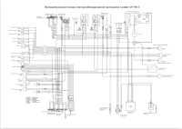
Электросхема на русском языке мотоцикла CFMoto модели CF150-С.
- Издательство: —
- Год издания: —
- Страниц: 1
- Формат: PDF
- Размер: 5,6 Mb

Руководство на английском языке по эксплуатации и техническому обслуживанию мотоциклов CFMoto V-Night модели CF150-2C.
- Издательство: Zhejiang CFMOTO Power Co., Ltd.
- Год издания: —
- Страниц: 68
- Формат: PDF
- Размер: 3,1 Mb

Руководство на английском языке по эксплуатации и техническому обслуживанию мотоциклов CFMoto модели CF250T-3 (V3).
- Издательство: —
- Год издания: —
- Страниц: 46
- Формат: PDF
- Размер: 15,0 Mb

Руководство на английском языке по эксплуатации и техническому обслуживанию мотоциклов CFMoto модели CF250T-5 (V5).
- Издательство: —
- Год издания: —
- Страниц: 45
- Формат: PDF
- Размер: 19,1 Mb
Руководство на русском языке по эксплуатации и техническому обслуживанию скутеров CFMoto Jet-Max модели CF250T-6A.
- Издательство: —
- Год издания: —
- Страниц: 51
- Формат: PDF
- Размер: 907 Kb

Руководство на английском языке по эксплуатации и техническому обслуживанию мотоциклов CFMoto 650NK модели CF650.
- Издательство: —
- Год издания: —
- Страниц: 124
- Формат: PDF
- Размер: 8,3 Mb
Руководство на русском языке по эксплуатации и техническому обслуживанию мотоциклов CFMoto 650NK модели CF650.
- Издательство: —
- Год издания: —
- Страниц: 124
- Формат: PDF
- Размер: 1,4 Mb
Руководство на английском языке по техническому обслуживанию и ремонту мотоциклов CFMoto 650NK модели CF650.
- Издательство: —
- Год издания: —
- Страниц: 442
- Формат: PDF
- Размер: 23,8 Mb
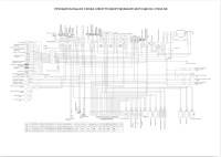
Электросхема на русском языке мотоцикла CFMoto модели CF650-NK.
- Издательство: —
- Год издания: —
- Страниц: 1
- Формат: PDF
- Размер: 10,3 Mb
Руководство на английском языке по техническому обслуживанию и ремонту двигателя CFMoto модели 172MM.
- Издательство: —
- Год издания: —
- Страниц: 108
- Формат: PDF
- Размер: 12,8 Mb
В руководстве представлена информация об устройстве и работе всех узлов и агрегатов мотоцикла.
- Издательство: Алфамер
- Год издания: —
- Страниц: 220
- Формат: —
- Размер: —
Руководство по техническому обслуживанию и ремонту скутеров производства Китая, Тайваня и Кореи с двигателями объемом от 50 до 200 cc и автоматической трансмиссией.
- Издательство: Алфамер
- Год издания: —
- Страниц: 240
- Формат: —
- Размер: —


Summary of Content for CFMOTO 650NK CF650-7US 2023 Motorcycle Owner’s Manual PDF
OWNERS
MANUAL
CF650-7US
650NK NERS
ANUAL
TABLE OF CONTENTS Foreword ……………………………………………………………………………………….. 8
Welcome ………………………………………………………………………………………………………..8 EVAP System (Evaporative Emission Control System) …………………………………………9 Catalytic Converter …………………………………………………………………………………………10
Introduction ………………………………………………………………………………….. 13 VIN and Engine Serial Number ………………………………………………………. 14 Speci cations ………………………………………………………………………………. 15 Operator Safety…………………………………………………………………………….. 18
General Safety Precautions …………………………………………………………………………….18 Owner Responsibilities ……………………………………………………………………………………22 Safe Riding Gear ……………………………………………………………………………………………23 Potential Hazard Warnings ………………………………………………………………………………26
Safety Decals and Locations …………………………………………………………. 31 Vehicle View …………………………………………………………………………………. 33
Rear Left View ……………………………………………………………………………………………….33 Front Right View …………………………………………………………………………………………….34
Controls and Features ………………………………………………………………….. 35 Clutch Lever ………………………………………………………………………………………………….35
Front Hand Brake Lever ………………………………………………………………………………….35 Handlebar Switch, LH …………………………………………………………………………………….36 Handlebar Switch, RH …………………………………………………………………………………….37 Throttle Grip ………………………………………………………………………………………………….37 Locks ……………………………………………………………………………………………………………38 Gear Shift Lever …………………………………………………………………………………………….40 Rear Brake Lever …………………………………………………………………………………………..41 Side Stand …………………………………………………………………………………………………….41 Passenger handhold and footrest …………………………………………………………………….42
TFT Instrument (Select markets)……………………………………………………. 43 Instrument Indicators ………………………………………………………………………………………43 Instrument …………………………………………………………………………………………………….43 Activation and Test …………………………………………………………………………………………43 Instrument Indicators ………………………………………………………………………………………44 Instrument Display (ECO Mode) ………………………………………………………………………47 Instrument Display (Sport Mode) ……………………………………………………………………..48 Instrument Menu ……………………………………………………………………………………………54
Operating Your Vehicle …………………………………………………………………. 75 Break-in Period ……………………………………………………………………………………………..75 Daily Safety Inspection ……………………………………………………………………………………76
Starting …………………………………………………………………………………………………………78 Starting O ……………………………………………………………………………………………………79 Shifting, Riding ………………………………………………………………………………………………79 Brake ……………………………………………………………………………………………………………81 Parking …………………………………………………………………………………………………………82
Safety Operation …………………………………………………………………………… 83 Safe Riding Technique ……………………………………………………………………………………83 Additional Cautions for High Speed Operation …………………………………………………..85
Maintenance …………………………………………………………………………………. 86 Severe Use De nition …………………………………………………………………………………….86 Key Points of Lubrication Schedule: ………………………………………………………………..87 Break-in Maintenance Schedule ………………………………………………………………………88 Periodic Maintenance Schedule ……………………………………………………………………….91 Clutch Lever Freeplay …………………………………………………………………………………….97 Took Kit ………………………………………………………………………………………………………..98
Fuel System …………………………………………………………………………………. 99 Fuel Tank ………………………………………………………………………………………………………99 Fuel Requirement …………………………………………………………………………………………100
Engine Assy ……………………………………………………………………………….. 101 Engine Oil Level Inspection ……………………………………………………………………………101
Change Engine Oil and Oil Filter …………………………………………………………………….102 Engine Oil Capacity ………………………………………………………………………………………104 Spark Plug …………………………………………………………………………………………………..105
Air Intake and Exhaust System ……………………………………………………. 106 Fuel & Exhaust Detecting System …………………………………………………………………..106 Air Intake Valve ……………………………………………………………………………………………106 Valve Clearance …………………………………………………………………………………………..107 Air Filter ………………………………………………………………………………………………………108
Cooling System ………………………………………………………………………….. 109 Radiator and Cooling Fan ……………………………………………………………………………..109 Radiator Hoses ……………………………………………………………………………………………109 Coolant ……………………………………………………………………………………………………….110 Coolant Level Inspection ……………………………………………………………………………….112 Coolant Filling ……………………………………………………………………………………………..113
Tire and Chain ………………………………………………………………………………114 Tire Speci cation ………………………………………………………………………………………….114 Tire Payload ………………………………………………………………………………………………..115 Tire Friction …………………………………………………………………………………………………116 Drive Chain Inspection ………………………………………………………………………………….117 Chain Tension Adjustment ……………………………………………………………………………..118
Brake System ……………………………………………………………………………… 120 Front Brake Lever Inspection …………………………………………………………………………120 Rear Brake Pedal Inspection …………………………………………………………………………120 Brake Fluid Level Inspection ………………………………………………………………………….121 Adding Brake Fluid ……………………………………………………………………………………….122 Brake Disc Inspection …………………………………………………………………………………..124 Brake Caliper Inspection ……………………………………………………………………………….124 Anti-lock Braking System (ABS) ……………………………………………………………………..125
Shock Absorber ………………………………………………………………………….. 126 Shock Absorber Inspection ……………………………………………………………………………126 Shock Absorber Inspection ……………………………………………………………………………127 Rear Shock Absorber Adjustment …………………………………………………………………..127
Electrical System and Light Signal ………………………………………………. 128 Battery ………………………………………………………………………………………………………..128 Light …………………………………………………………………………………………………………..133 Fuse …………………………………………………………………………………………………………..134
Catalytic Converter……………………………………………………………………… 135 Fuel Evaporation System…………………………………………………………….. 136 Motorcycle cleaning and storage…………………………………………………. 137
General Precautions …………………………………………………………………………………….137
Washing Vehicle …………………………………………………………………………………………..138 Protect the Surface ………………………………………………………………………………………139 Windshield and Other Plastic …………………………………………………………………………139 Chrome and Aluminum ………………………………………………………………………………….139 Preparation for Storage …………………………………………………………………………………141 Preparation After Storage ………………………………………………………………………………142 Transporting Your Vehicle ……………………………………………………………………………..142
General troubles and causes ………………………………………………………. 143 Reporting Safety Defects ………………………………………………………………………………145
Warranty Information ………………………………………………………………….. 146 Change of Ownership …………………………………………………………………………………..146
CFMOTO LIMITED WARRANTY ……………………………………………………. 147 Telematics BOX (T-BOX) and CFMOTO Ride App …………………………. 154
8
FOREWORD Foreword
Welcome Thank you for purchasing a CFMOTO vehicle, and welcome to our world-wide family of CFMOTO enthusiasts. Be sure to visit us online at www.cfmoto.com for the latest news, new product introductions, upcoming events, and more. CFMOTO is an international company that specializes in the development, manufacture, and marketing of all-terrain vehicles, utility vehicles, large displacement motorcycles, and their core components. Founded in 1989, CFMOTO is devoted to the development of independent brand cultivation and R&D innovation. CFMOTO products are currently distributed through more than 2000 companions worldwide in more than 100 countries and regions. CFMOTO is edging into the advanced ranks in the world of powersports, and aims to supply superior products to dealers and fans globally. For safe and enjoyable operation of your vehicle, be sure to follow the instructions and recommendations in this owners manual. Your manual contains instructions for minor maintenance. Information about major repairs is outlined in the CFMOTO Service Manual. Your CFMOTO dealer knows your vehicle best and is interested in your total satisfaction. Be sure to return to your dealership for all of your service needs during, and after, the warranty period. Due to constant improvements in the design, quality, or con guration of production components, some minor discrepancies may result between the actual vehicle and the information presented in this publication. CFMOTO reserves the right to change product features, speci cations and components without notice or incurring obligation to the purchaser. Depictions and/or procedures within are intended for reference use only. The most current version of this manual may be available on the CFMOTO consumer website of the market you reside in.
9
FOREWORD Before every ride, please inspect your vehicle and follow the basic maintenance procedures before riding. Please keep this manual together with your vehicle, even when transferring the vehicle to others. Zhejiang CFMOTO power Co., Ltd reserves the nal explanation rights of the owner’s manual.
DANGER Operating, servicing and maintaining on-road or o -road vehicles can expose you to chemicals including engine exhaust, carbon monoxide, phthalates, and lead, which are known to cause cancer and birth defects or other reproductive harm. To minimize exposure, avoid breathing exhaust, do not idle the engine except as necessary, service your vehicle in a well-ventilated area and wear gloves or wash your hands frequently when servicing your vehicle.
EVAP System (Evaporative Emission Control System) (If equipped) When required by environmental emissions regulations, this vehicle is manufactured with a fuel evaporation system (EVAP) to prevent fuel vapors entering the atmosphere from the fuel tank and fuel system. During routine maintenance, visually inspect all hose connections for leaks or blockage. Ensure the hoses are not clogged or kinked, which could damage the fuel pump or distort the fuel tank. No other maintenance is necessary. Contact your dealer if repair is required. Do not modify the EVAP system. Modifying any part of this system will violate environmental emissions regulations.
10
FOREWORD Catalytic Converter CAUTION: Please pay attention to the following to protect your catalytic converter:
Use only unleaded gasoline. Even gasoline that contains a little lead could damage the reactive metals contained in the catalytic converter and disable it.
Never add rust preventive oil or engine oil into the muffler. Doing so could damage the catalytic converter.
NOTE Some features described within this manual may not apply to models in your market. All descriptions and directions given are from the operators perspective when properly seated.
Information in this publication is based on the latest production available at the time of approval for printing. CFMOTO reserves the right to make changes at any time without notice and without incurring any obligation.
11
FOREWORD Signal Words A signal word calls attention to a safety message or messages, a property damage message or messages, and designates a degree or level of hazard seriousness. The standard signal words in this manual are DANGER, WARNING, CAUTION and NOTE. The following signal words and symbols appear throughout this manual and on your vehicle. Your safety is involved when these words and symbols are used. Become familiar with their meanings before reading the manual:
DANGER This safety alert and icon indicates a potential hazard that may result in serious injury or death.
WARNING This safety alert and icon indicates a potential hazard that may result in minor or moderate personal injury and/or damage to the vehicle.
CAUTION This safety alert and icon indicates a potential hazard that may result in damage to the vehicle.
NOTE A note or notice will alert you to important information or instructions.
12
FOREWORD
READ THE OWNERS MANUAL FOLLOW ALL INSTRUCTIONS AND WARNINGS
WARNING Read, understand, and follow all of the instructions and safety precautions in this manual and on all product labels. Failure to follow the safety precautions could result in serious injury or death.
WARNING The engine exhaust gas from this product contains CO, which is deadly gas and could cause headaches, giddiness, loss of consciousness, or even death.
13
INTRODUCTION Introduction
Thank you for purchasing a CFMOTO vehicle, and welcome to our world-wide family of CFMOTO enthusiasts. For safe and enjoyable operation of your vehicle, be sure to follow the instructions and recommendations in this owners manual. Information about major repairs are outlined in the CFMOTO Service Manual, and should only be performed by a CFMOTO service dealer and technician. Be sure to return to your dealership for all of your service needs during, and after, the warranty period.
If you have questions or concerns about your vehicle All questions or concerns related to your vehicle should be directed to your local CFMOTO dealer rst. Your dealer knows your vehicle best and is interested in your total satisfaction. In the event your local dealer is unable to resolve a product issue or concern, you can reach a CFMOTO customer service representative depending on the market you reside in: For USA: Please contact CFMOTO POWERSPORTS, INC. TEL: 763-398-2690, by e-mail: info@ cfmotousa.com, or online: https://cfmotousa.com/customer-care/customer-care-contact. Please note that customer service does not have authority to approve or deny warranty, and cannot provide technical repair data, diagnosis, or instructions. For CANADA: Please contact CANADA MOTOR IMPORT INC. TEL: 1-418-227-2077, or online: https:// www.cfmoto.ca/en/customer-care/. For a safety concern related to your Canadian vehicle, you may report your concern to Transport Canada Defect Investigation and Recalls Division by mail, telephone, or online using the contact information below: Mailing address: Transport Canada — ASFAD, 330 Sparks Street, Ottawa, ON, K1A 0N5 TEL: 819-994-3328 (Ottawa-Gatineau area or international) or toll-free: 1-800-333-0510 (In Canada) Online: http://www.tc.gc.ca/recalls
14
INTRODUCTION VIN and Engine Serial Number
Be sure to record the VIN number, engine serial number and name plate information in the spaces below:
Vehicle identi cation number:
Engine serial number:
1 VIN No. 2 Engine serial No.
1
2
15
SPECIFICATIONS Speci cations
650-7US Performance Max. power 60.3 Hp (45 kw) / 8750 rpm Max. torque 41.3 Ft-lb (56 Nm) / 7000 rpm Top designed speed 105.6 mph (170 km/h) Size Length 83.2 in. (2114 mm) Width 32.7 in. (830 mm) Height 43.3 in. (1100 mm) Wheelbase 55.7 in. (1415 mm) Ground clearance 5.9 in. (150 mm) Curb weight 454.2 lb. (206 kg) Engine Type Cylinder in-line, two cylinder, four stroke, liquid cooled Displacement 649 mL BoreStroke 3.27 in. 2.36 in. (83 mm 60 mm) Compression ratio 11.30.51 Starting system Electric starter Fuel supplying system EFI Ignition control system ECU Ignition Lubricating system Pressure / splash lubrication
16
SPECIFICATIONS
Engine oil type First choice: SAE 10W-40 SJ JASO-MA2
Second choiceSAE 10W-30 SJ / SAE 10W-50 SJ / SAE 20W-40 SJ / SAE 20W-50 SJ JASO-MA2
Idle Speed 1450 r/min 150 r/min Transmission Transmission type 6-speed, manual gear shift Clutch type Wet, multi-disc, manual Driving system Chain drive Primary reduction ratio 2.095 Final reduction ratio 3.067
Gear ratio
1st 2.353 2nd 1.714 3rd 1.333 4th 1.111 5th 0.966 6th 0.852
Chassis
Tire size Front 120/70ZR17 M/C 58W Rear 160/60ZR17 M/C 69W
Rim size Front 3.517 MT Rear 4.517 MT
Capacity of fuel tank 4.5 gal 0.13 gal (17 0.5 L) Fuel consumption 1.32 gal (5.0 L) / 100 km
17
SPECIFICATIONS Electric components Battery 12V/9 Ah Headlight LED Tail / brake light LED Turn signals LED
18
OPERATOR SAFETY Operator Safety
General Safety Precautions
WARNING Failure to heed the warnings contained in this manual can result in serious injury or death. This vehicle is not a toy and can be hazardous to operate. Read this owners manual. Understand all safety warnings, precautions and operating procedures before operating this vehicle.
Riding Restrictions This vehicle is an ADULT VEHICLE ONLY. The operator must acquire a driving license as required by local laws and regulations.
Know Your Vehicle As the operator of the vehicle, you are responsible for your personal safety, the safety of others, and the protection of the environment. Read and understand your owner’s manual, which includes valuable information about all aspects of your vehicle, including safe operating procedures.
19
OPERATOR SAFETY Equipment Modi cations CFMOTO is concerned with the safety of our customers and for the general public. Therefore, we strongly recommend that consumers do not install on a vehicle, any equipment that may increase the speed or power of the vehicle, or make any other modi cations to the vehicle for these purposes. Any modi cations to the original equipment of the vehicle create a substantial safety hazard and increase the risk of body injury. The warranty on your vehicle is terminated if any unapproved accessory equipment has been added to the vehicle, or if any modi cations have been made to the vehicle that increase its speed or power.
Avoid Carbon Monoxide Poisoning All engine exhaust contains carbon monoxide, a deadly gas. Breathing carbon monoxide can cause headaches, dizziness, drowsiness, nausea, confusion and eventually death. Carbon monoxide is a colorless, odorless, tasteless gas that may be present even if you do not see or smell any engine exhaust. Deadly levels of carbon monoxide can collect rapidly, and you can quickly be overcome and unable to save yourself. Also, deadly levels of carbon monoxide can linger for hours or days in enclosed or poorly ventilated areas. To prevent serious injury or death from carbon monoxide:
Never run the vehicle in poorly ventilated or partially enclosed areas. Never run the vehicle outdoor where engine exhaust can be drawn into a building through openings
such as windows and doors.
20
OPERATOR SAFETY Avoid Gasoline Fires and Other Hazards Gasoline is extremely ammable and highly explosive. Fuel vapors can spread and be ignited by a spark or ame many feet away from the engine. To reduce the risk of re or explosion, follow these instructions:
Strictly adhere to proper fueling procedures. Never start or operate the engine if the fuel cap is not properly installed. Gasoline is poisonous and
can cause injury or death. Never siphon gasoline by mouth. If you swallow gasoline, get any in your eye (s) , or inhale gasoline vapor, see a doctor immediately. If gasoline spills on you, wash with soap and water and change your clothes.
Fuel Minimum Octane Rating and Safety Warnings The recommended fuel for your vehicle is 87 octane or premium unleaded only (a maximum blend of 10% ethanol is allowed). Non-oxygenated (ethanol-free) fuel is recommended for best performance in all conditions.
21
OPERATOR SAFETY WARNING
Gasoline is highly ammable and explosive under certain conditions. Allow the engine and exhaust system to cool before lling the tank. Always exercise extreme caution whenever handling gasoline. Always refuel with the engine stopped, and outdoors or in a well ventilated area. Do not smoke or allow open ames or sparks in or near the area where refueling is performed, or where gasoline is stored. Do not over ll the tank. Do not ll to the tank neck. If gasoline spills on your skin or clothing, immediately wash it off with soap and water and change clothing. Never start the engine or let it run in an enclosed area. Engine exhaust fumes are poisonous and can cause loss of consciousness or death in a short time. The engine exhaust from this product contains chemicals known to cause cancer, birth defects or other reproductive harm. Operate this vehicle only outdoors or in well-ventilated areas.
Avoid Burns from Hot Parts The exhaust system and engine become hot during operation. Avoid contact during and shortly after operation to avoid burns.
22
OPERATOR SAFETY Owner Responsibilities Be Quali ed and Responsible Read this Owners Manual and the warning decals on this vehicle carefully. Take a safety training course on open areas if available. Practice at low speeds. Higher speeds require greater experience, knowledge and suitable riding conditions. Become completely familiar with the operational controls and the general operation of the vehicle. This vehicle is an ADULT VEHICLE ONLY. The operator must acquire a driving license as required by local laws and regulations. Operators must be tall enough with physical capacity to: be properly seated, hold the handlebar with both hands, fully stroke the clutch lever with the left hand, fully stroke the brake lever with the right hand, fully stroke the foot brake lever with the right foot, be able to rmly plant both feet on the foot pegs, and be able to balance the vehicle with the feet when stopped. Carrying a Passenger
The operator must acquire a driving license as required by local laws and regulations for models equipped to carry passengers.
Only carry one passenger. The passenger must be properly seated in the passenger seat. The passenger should be tall enough to always be properly seated when holding handhold, and feet rmly planted on the foot pegs.
Instruct the passenger to read the vehicles safety labels. Never carry a passenger who has used drugs or alcohol, or is tired or ill. These slow reaction time
and impair judgment. Never carry a passenger if you judge their ability or judgment is insu cient to concentrate on the
terrain conditions and adapt accordingly.
23
OPERATOR SAFETY Safe Riding Gear Always wear clothing suited to the type of riding for the driver and passenger, includes: 1 An approved helmet 2 Eye protection. 3 Gloves 4 Long sleeve shirts or jackets 5 Long pants 6 Over-the-ankle boots
According to the actual weather, you may need extra apparel, such as anti-fog eye protection, thermal underwear and a face guard for cold weather. The operator must never wear loose clothing that may get entangled in the vehicle or on tree branches and shrubs.
Helmet and Eye Protection An approved helmet can prevent a serious head injury if an accident occurs. Please note that even the best helmet is no guarantee against injury. The helmet you choose should meet the standard for your country or area. A closed-face helmet with face shield will be better at preventing impacts from insects, flying rocks, dust and scattered debris, etc.
1
2
3 4
5
6
24
OPERATOR SAFETY An open-face helmet cannot o er the same protection for your face and jaw. Please wear detachable face masks and goggles when wearing an open-face helmet. Do not depend on eyeglasses or sunglasses for eye protection, as they are not rated for impact protection. Debris may y up and or break the lens, causing eye injury. Use tinted masks or goggles only during the day in bright light, do not use them at night or in poor light. They may a ect your ability to distinguish colors. Do not use them if your color discrimination is a ected. Gloves Full- nger gloves could protect your hands from wind, sun, heat, cold, and splash. Well- tted gloves are helpful for steering and relieve hand fatigue. If the gloves are too heavy, it will be di cult to operate the vehicle. A pair of strong motorcycle gloves o er protection for your hands in the event of an accident or turnover. Snowmobile gloves o er better protection when operating in cold areas. Jackets, Pants and Motorcycle Suits Wear a jacket or a long sleeved shirt and long pants, or a full riding suit. Quality protective gear will provide comfort, and it can help you avoid being distracted by adverse environmental elements. In case of an accident, good quality protective gear made of sturdy material may prevent or reduce injury. In cool-weather riding, protect yourself against hypothermia. Hypothermia, a condition of low body temperature, can cause loss of concentration, slowed reactions and loss of smooth, precise muscle movement. In cool conditions, proper protective gear like a windproof jacket and insulated layers of clothing are essential. Even while riding at moderate temperatures, you can feel very cold due to the wind. Protective gear that is appropriate for cold-weather riding may be too hot when stopped. Dress in layers so that clothing can be removed as desired. Topping the protective gear with a windproof outer layer can prevent cold air from reaching the skin.
25
OPERATOR SAFETY Boots Always wear closed-toe, over-the-ankle boots. Sturdy over-the-ankle boots with non-slip soles o er more protection, and allow you to plant your foot properly on the foot pegs. Avoid long shoelaces that could get tangled in the vehicle components. For winter riding conditions, rubber-soled boots with either nylon or leather uppers and removable felt liners are best suited. Avoid rubber rain boots. Rubber rain boots may get trapped behind the foot brake pedal, impairing proper operation.
Other Riding Gear
Rain Gear When riding in rainy weather, a rain suit or a waterproof riding suit is recommended. On long rides, it is a good idea to carry rain gear. Keeping clothes dry results in being much more comfortable and alert.
Hearing Protection Long-term exposure to wind and engine noise when riding can cause permanent hearing loss. Properly worn hearing protective devices such as earplugs can help prevent hearing loss. Check local laws before using any hearing protective devices.
26
OPERATOR SAFETY Potential Hazard Warnings
WARNING POTENTIAL HAZARD: Operating this vehicle without proper instruction. WHAT CAN HAPPEN: The risk of an accident is greatly increased if the operator does not know how to operate the vehicle properly in di erent situations and on di erent types of terrain. HOW TO AVOID THE HAZARD: Beginning and inexperienced operators should complete a safety training course if offered by dealer. Operators should regularly practice the skills learned in the course and any operating techniques described in the owners manual.
WARNING
POTENTIAL HAZARD: Failure to follow the age recommendations for this vehicle. WHAT CAN HAPPEN: Severe injury and/or death could occur if a child under the minimum age recommendation operates this vehicle. Even though a child may be within the recommended age group for operating, he/she may not have the skills, abilities, or judgment needed to operate safely and could be susceptible to accident or injury. HOW TO AVOID THE HAZARD: The operator must acquire a driving license as required by local laws and regulations.
27
OPERATOR SAFETY WARNING
POTENTIAL HAZARD: Operating this vehicle without wearing approved helmet, eye protection, and protective clothing. WHAT CAN HAPPEN: Operating without an approved helmet increases the risk of a severe head injury or death in the event of an accident. Operating without eye protection could result in an accident and could increase the chance of a severe eye injury in the event of an accident. Operating without protective clothing could increase the chance of a severe injury. HOW TO AVOID THE HAZARD: Always wear an approved helmet that ts properly. Always wear eye protection (goggles or face shield) , gloves, long-sleeved shirt or jacket, long pants, and over-the-ankle boots.
WARNING POTENTIAL HAZARD: Operating the vehicle after consuming alcohol or drugs. WHAT CAN HAPPEN: Consumption of alcohol and/or drugs could seriously affect operator judgment. Reaction time may be slower and operator balance and perception could be affected. Consumption of alcohol and/or drugs before or while operating a vehicle could result in an accident causing severe injury or death. HOW TO AVOID THE HAZARD: Never consume alcohol or drugs before or while operating the vehicle.
28
OPERATOR SAFETY WARNING
POTENTIAL HAZARD: Operating at excessive speeds.
WHAT CAN HAPPEN: Excessive speed increases the operators chance of losing control, which can result in an accident.
HOW TO AVOID THE HAZARD: Always operate at a speed thats proper for the terrain, visibility and operating conditions, and your experience.
WARNING
POTENTIAL HAZARD: Attempting slides, jumps, and other stunts.
WHAT CAN HAPPEN: Attempting stunts increases the chance of an accident, including an overturn.
HOW TO AVOID THE HAZARD: Never attempt slides, jumps, or other stunts.
29
OPERATOR SAFETY WARNING
POTENTIAL HAZARD: Failure to inspect the vehicle before operating. Failure to properly maintain the vehicle.
WHAT CAN HAPPEN: Poor maintenance increases the possibility of an accident or equipment damage.
HOW TO AVOID THE HAZARD: Always inspect your vehicle before each use to make sure it is in safe operating condition. Always follow the inspection and maintenance procedures and schedules described in the owners manual.
WARNING
POTENTIAL HAZARD: Operating this vehicle with improper tires, or with improper or uneven tire pressure.
WHAT CAN HAPPEN: Use of improper tires, or operation of the vehicle with improper or uneven tire pressure, could cause loss of control or an accident.
HOW TO AVOID THE HAZARD: Always use the size and type of tires specified in the owners manual. Always maintain proper tire pressure.
30
OPERATOR SAFETY WARNING
POTENTIAL HAZARD: Operating the vehicle with improper modi cations.
WHAT CAN HAPPEN: Improper installation of accessories or modi cation of the vehicle may cause changes in handling which could lead to an accident.
HOW TO AVOID THE HAZARD: Never modify the vehicle through improper installation or use of accessories. All parts and accessories added to the vehicle must be genuine parts or equivalent components designed for use on this vehicle, and they should be installed and used according to approved instructions. Consult your dealer for more information.
31
SAFETY DECALS AND LOCATIONS Safety Decals and Locations
Read and understand all of the safety and information labels on your vehicle for safe and proper operation. Never remove any labels from your vehicle. If a label becomes di cult to read or falls o , a replacement is available from your CFMOTO dealer.
32
SAFETY DECALS AND LOCATIONS
33
CONTROLS & FEATURES
1: Instrument 2: Clutch lever 3: Handlebar switch, LH 4: Ignition switch lock 5: Fuel tank lock 6: Gear shift lever 7: Seat lock 8: Passenger handhold 9: Footrests
Vehicle View
Rear Left View
1
2
3 5
76
4
8
9
34
CONTROLS & FEATURES
10: Throttle grip 11: Handle bar switch, RH 12: Front hand brake lever 13: Rear brake lever
Front Right View
11 10
12
13
35
CONTROLS & FEATURES Controls and Features
Clutch Lever Clutch lever 1 is on the left side of handlebar. The clutch is cable-operated type. Adjust the clutch levers distance to the handlebar by turning the clutch lever adjusting knob.
Front Hand Brake Lever Front hand brake lever 2 is on the right side of handlebar. Front brake caliper activates braking by pulling in the hand brake lever. Adjust the braking levers distance to the handlebar by turning the hand brake lever adjusting knob.
1
2
Adjusting knob
Adjusting knob
36
CONTROLS & FEATURES Handlebar Switch, LH Left handlebar switch 1 is on the left side of the handlebar.
Function of left handlebar switch
2 Dimmer push switch
Turn to this position, high beam lights on. Turn to this position, low beam lights on.
3 Mode button MODE Short press to shift between touring mode and sport mode.
4 Turning l ight switch
Push this switch to the right, the right turning light will activate. Push this switch to the left, the left turning light will activate.
5 Horn button Short press, the horn will sound.
6 passing light switch
Short press this button, passing light will ash.
1
2
4
3
5
6
37
CONTROLS & FEATURES Handlebar Switch, RH Right handlebar switch 1 is on the right side of the handlebar. Right handlebar switch function
2 Stop switch
Turn to this position, the vehicle turns o . Turn to this position, the vehicle is ready to start. Push this button to start the vehicle.
3 Hazard asher switch
Short press to turn on the hazard asher light.
4 Light switch
Turn to this position, headlight, position light and taillight will be on. Turn to this position, position light and taillight will be on.
Turn to this position, headlight, position light and taillight will be o .
Throttle Grip Throttle grip 5 is on the right side of handlebar.
1
5
4
2
3
38
CONTROLS & FEATURES Locks
Ignition switch 1
Handlebar lock Turn the handlebar to the left, then turn the key to the lock indicator to lock the handlebar.
Turn o Turn the key to this position, the engine cannot be started and the vehicle power circuit is disconnected.
Start
Turn the key to this position, the engine can be started and the vehicle power circuit is connected.
1
39
CONTROLS & FEATURES Fuel Tank Lock
Follow the items below before opening the fuel tank: The vehicle is stopped. Engine is o .
Open the fuel tank lock cover. Insert the key and turn to release the lock. Open the fuel tank cap.
2
40
CONTROLS & FEATURES Seat Lock 1
The seat lock is on the left side of the vehicle. The seat can be removed by inserting the key and turning to release the lock.
Gear Shift Lever The gear shift lever 2 is on the left side of the engine.
1
6 5 4 3 2 N 1
2
41
CONTROLS & FEATURES Rear Brake Lever The rear brake lever 1 is on the right side of the engine. Activate the rear brake by pushing down on the rear brake lever.
Side Stand The side stand 2 is on the left side of the vehicle, and is used for parking. NOTE: When the side stand is down, the engine starting system only activates in neutral gear.
1
2
42
CONTROLS & FEATURES Passenger handhold and footrest A passenger handhold 1 is mounted on the motorcycle seat for passenger to hold on during riding.
Footrests 2 are mounted on the motorcycle for the operator and passenger.
1
2
43
CONTROLS & FEATURES
Instrument Indicators TFT Instrument (Select markets)
Instrument Instrument is located at the front of handlebar, there are two function areas: 1 Instrument indicators area 2 Instrument display area
Activation and Test Activation The instrument is activated when vehicle power is on.
Test Display area shows welcome words and indicators ash in short time for self inspection. All instrument buttons is invalid at this time until the starting video is nished.
2 11
44
CONTROLS & FEATURES Instrument Indicators
1
5
6
7
1
2
3
4
8
45
CONTROLS & FEATURES Ref Symbol Function
1 Flash Indicator ashes when the turning light turns on.
2 Keep on Position light indicator will be on when position light turns on.
3 Keep on
When electric circuit is connected and engine is off, EFI fault indicator will be on. If the engine is not off and the indicator is still on, it means the vehicle detects any fault, the fault will be displayed on the dashboard for warning. Please stop the vehicle in place according to tra c regulations when EFI fault indicator is on and contact your CFMOTO dealer soon.
4 Flash / Keep on
When the vehicle is powered on, the ABS indicator will flash until the vehicle begins to move at speeds above 3-5 mph (5km/ h~8km/h) and remains off until the next power on or a fault occurs. This is normal.If a fault is detected, the ABS indicator turns on and stays on. The ABS is automatically deactivated in a fault condition, but the vehicle retains full basic braking function. Please drive at slow speeds, avoid hard braking, and contact your CFMOTO dealer as soon as possible.
5 Keep on High beam indicator will be on when high beam lamp turns on.
46
CONTROLS & FEATURES
6 Flash / Keep on
Fuel level indicator will be on when fuel level is very low. Please plan your trip reasonably and ll fuel soon. When detect faults, the fuel level indicator will ash. Please contact your CFMOTO dealer soon.
7 Flash
Coolant temp. indicator will flash when the coolant is in high temperature. Please stop the vehicle in place according to traffic regulations to wait for cooling down the temperature. If the coolant temp. indicator flashes frequently, please contact your CFMOTO dealer soon.
8 Keep on Oil pressure indicator lights on when the oil level is very low or oil pump can not work normally or the oil tube may be blocked, stop the engine immediately and inspect the reason.
47
CONTROLS & FEATURES Instrument Display (ECO Mode)
1 2 3
4
5
6
9 8
7
1 Clock 5 Coolant Temp. 9 Optional Info 2 Display 2 Speed Display 6 Fuel Level 10 Engine RPM 3 Blue Tooth 7 Optional Info 1 Display 4 Gear Position 8 Vehicle Mode
10
48
CONTROLS & FEATURES Instrument Display (Sport Mode)
1 3
4
10
9
7
8 2 5 6
1 Clock 5 Coolant Temp. 9 Optional Info 2 Display 2 Speed Display 6 Fuel Level 10 Engine RPM 3 Blue Tooth 7 Optional Info 1 Display 4 Gear Position 8 Vehicle Mode
49
CONTROLS & FEATURES Clock Display the current time. The clock is adjustable and can be shifted between 12 hours and 24 hours through the menu.
Speed Display Display the current vehicle speed. Speed unit could be shifted between km/h and mph through the menu operation.
PM 10:50 22:50
124 mph
199 km/h
50
CONTROLS & FEATURES Blue Tooth When cellphone is paired with the instrument, this area will appear the blue tooth symbol, cellphone signal strength and cellphone battery gauge.
Gear Position Display the current gear position. Neutral position is displayed in green color.
N
51
OPERATING YOUR VEHICLE Coolant Temperature The coolant temperature indicator consists of bars, the more bars light up, the hotter the coolant. When the last bar lights on and the coolant temperature indicator ashes, it means the temperature reach the danger limit.
WARNING Overheating could lead to engine damage. When coolant temperature reaches the top limit, please stop well the vehicle to wait for cooling down. Check and correct the coolant level when coolant system is totally cooled down. If the coolant temperature indicator ashes in high frequency, please contact your CFMOTO authorized dealer for service.
Fuel Level The fuel level display consists of bars, More bars are lighted, more fuel is in the fuel tank. When the fuel reserve is closed to limited level, the last indicator bar will light on, fuel level indicator will also light on, and it will appear the reminding warning: insu cient fuel in the home interface. Please arrange well the travel and re ll fuel soon. Little fuel quantity may lead to damage of fuel pump.
52
OPERATING YOUR VEHICLE Optional Information Customer could select two items that displayed in the home interface. Optional Info 1ODO, trip1, trip 2. Optional Info 2Voltage, instantaneous fuel consumption, trip 1 travel time, trip 2 travel time, total odometer travel time, trip 1 average fuel consumption, trip 2 average fuel consumption, total odometer average fuel consumption, trip 1 average speed, trip 2 average speed, total odometer average speed.
Vehicle Mode The vehicle could shift the drive mode between SPORT mode and ECO mode to meet di erent driving experience.
ECO SPORT
53
OPERATING YOUR VEHICLE Engine RPM Please avoid high engine RPM during break-in period.
In order to increase the engine life, please keep RPM away from the red area. Before nishing warming the engine, do not run in high engine RPM.
54
OPERATING YOUR VEHICLE Instrument Menu Adjust the instrument setting through the menu for better driving experience. Long press the ENTER button on the handlebar switch to enter into instrument menu.
WARNING Instrument menu can be entered only when the vehicle is stopped and safety.
Instrument Switches Instrument switches are located on the right side of left handlebar, used for operating instrument functions.
Short press to choose the upper item.
ENT Short press to enter into next menu. Long press to enter into menu from home interface. Short press to return back to the last item. Long press in menu interface to return back to home interface.
Short press to choose the next item.
55
OPERATING YOUR VEHICLE Voltage and Coolant Temp. Long press ENTER button to enter into menu. Short press or to mark Information item, press ENTER button to enter into the item. Voltage and coolant temp. information is displayed in this information list.
Warning The instrument displays the fault warning and fault content when the vehicle detects faults. Please eliminate the vehicle fault soon when appears fault warning, contact your authorized CFMOTO dealer for service if necessary. Before eliminated, the fault warning will appear in the instrument for ten seconds every time when start the vehicle. Please enter into the menu-warning to check the fault content
56
OPERATING YOUR VEHICLE Long press ENTER to enter into menu. Short press or to select the Information, press ENTER to open the select item. Short press or to select warning, press ENTER to open warning item. Warning item will display all current faults of the vehicle, please contact CFMOTO authorized dealer to eliminate all the faults.
Example without fault.Example with fault.
57
OPERATING YOUR VEHICLE Service The vehicle has a service interval after break-in period. The instrument records the travel mileage and reminds the owner for vehicle maintenance when 500km close to the next service time. When the time is near to the service time, the instrument will display service warning for ten seconds every time when start the vehicle to remind service.
Long press ENTER to enter into menu. Short press or to select Information, press ENTER to open the select item. Short press or to select Service, press ENTER to open service item, then check the latest service mileage. Finish the maintenance in your CFMOTO authorized dealer ship and reset for the new service interval.
58
OPERATING YOUR VEHICLE Miles Info The following information is recorded for trip 1, trip 2 and ODO
1Mileage 2Speed 3Consumption 4Riding time Long press ENTER to enter into the menu. Short press or button to select Information item, press ENTER to open the item. Short press or button to select the Trip info, press ENTER to open trip info item. Short press or button to select desired item, press ENTER to open the next menu.
59
OPERATING YOUR VEHICLE Version Info Check the current software and hardware version of the vehicle. Long press ENTER to enter into menu. Short press or button to select Information, press ENTER button to open the information item. Short press or button to select the software version or hardware version, press ENTER button to open the select item.
60
OPERATING YOUR VEHICLE Units Shift the unit for speed, time and temperature through instrument operation. Long press ENTER button to enter into the menu. Short press or button to select Settings, press ENTER button to open setting item. Short press or button to select units, press ENTER button to open the unit setting item. Short press or button to select the desired unit, press ENTER to open the unit item.
Short press or button to select desired format, press ENTER to finish the unit shifting.
61
OPERATING YOUR VEHICLE Connection Pair the cellphone with instrument by bluetooth, then navigation, calling function can be used. Navigation function can be used with CFMOTO APP. Follow the steps to pair the bluetooth: Long press ENTER to enter into the menu. Short press or button to select Settings, press ENTER button to open the setting item. Short press or button to select Connection, press ENTER button to open the device connection item.
Short press or button to select Bluetooth button, press ENTER button to open bluetooth item.
62
OPERATING YOUR VEHICLE Make sure the cellphone bluetooth is open. Short press or button to select Connect a new device, press ENTER button to search devices. Devices that have been connected will be recorded in the menu. Select the device to pair directly. Display connected after nish pairing.
63
OPERATING YOUR VEHICLE Follow the steps to eliminate the device paired before: Long press ENTER to enter into the menu. Short press or to select Settings, press ENTER to open the setting item. Short press or to select the device connection, press ENTER to open the device connection item. Short press or to select Delete connections, press ENTER button to open the item. Short press or to select the desired device or all of the devices, press ENTER to delete. Short press or to select Con rm or Cancel, press ENTER button to delete the devices or return back to the last item.
64
OPERATING YOUR VEHICLE Optional Info 1 Choose one item from optional information 1 to display in the home interface. Long press ENTER to enter into the menu. Short press or button to select Settings, press ENTER button to open the setting item. Short press or button to select Optional Info 1, press ENTER button to open the item.
Short press or button to select desired item, press ENTER button to con rm the choice.
65
OPERATING YOUR VEHICLE Optional Info 2 Choose one item from optional information 2 to display in the home interface. Long press ENTER to enter into the menu. Short press or button to select Settings, press ENTER button to open the setting item. Short press or button to select Optional Info 2, press ENTER button to open the item.
Short press or button to select desired item, press ENTER button to con rm the choice.
66
OPERATING YOUR VEHICLE Brightness In addition to the automatically adjustment of the brightness, the instrument brightness can also be adjusted by manual according to the menu. Long press ENTER to enter into the menu. Short press or button to select Settings, press ENTER button to open the item. Short press or button to select Brightness, press ENTER to open the item. Short press or button to select the class of brightness, press ENTER to confirm the choice.
67
OPERATING YOUR VEHICLE Trip Reset Reset trip data by manual. Long press ENTER to enter into the manual. Short press or button to select Settings, press ENTER button to open the item. Short press or button to select Trip 1 Reset or Trip 2 Reset, press ENTER button to open the item. Short press or button to select OK or Cancel, press ENTER to reset trip or return back to last item.
68
OPERATING YOUR VEHICLE Time Settings Adjust the instrument time. Long press ENTER to enter into menu. Short press or to select Settings, press ENTER to open the item.. Short press or to select Time Settings, press ENTER to open the item. 12 hour: Short press or to select AM or PM, press ENTER to adjust the time. Short press or to adjust hour, press ENTER button to enter into minute, short press or to adjust minutes. 24 hour: Short press or to adjust hour, press ENTER to enter into minute, short press or to adjust minutes.
69
OPERATING YOUR VEHICLE Language Shift the dashboard language between Chinese and English. Long press ENTER to enter into menu. Short press or to select Settings, press ENTER button to open the item. Short press or to select Language, press ENTER button to open the item. Short press or to select desired language, press ENTER to con rm the selection.
70
OPERATING YOUR VEHICLE Reset All Reset all settings back to factory status.
NOTICE This function can not reset odometer and related function.
Long press ENTER to enter into the menu. Short press or button to select Settings, press ENTER button to open the item. Short press or button to select Reset all, press enter to open the item. Short press or button to select OK or Cancel to reset the instrument or return back to last item.
71
OPERATING YOUR VEHICLE Navigation Pair cellphone with the instrument, turn on CFMOTO APP then navigation function can be used. Open the navigation in CFMOTO APP, then the instrument shifts into navigation interface automatically.
Open the navigation by manual: Long press ENTER button to enter into the manual. Short press or button to select Navigation, press ENTER button to open the item. If CFMOTO APP does not activate, the instrument will display Please Open CFMOTO APP For Navigation
72
OPERATING YOUR VEHICLE The instrument will display navigation interface when it activates in the cellphone.
485m Distance to the next crossroads.
Tra c navigation symbol
Remaining distance to the destination.
Estimated arrival time
73
OPERATING YOUR VEHICLE Telephone This function is available when instrument is paired with cellphone by bluetooth. (Cellphone should connect with earphone and the instrument) If instrument does not pair with cellphone bluetooth, it will display reminding Please Connect Bluetooth Correctly. Please pair bluetooth according to Device connection.
When comes a call during driving, the call number will be displayed in the instrument, short press ENTER to accept the call. Short press CANCEL to hang up the call.
74
OPERATING YOUR VEHICLE Telephone item will record all numbers that called in during this bluetooth connection. The records will be reseted when power o . Check the latest calls: Press or button to select Telephone, press ENTER button to open the item.
Press or button to select the latest calls, press ENTER to open the item.
75
OPERATING YOUR VEHICLE Operating Your Vehicle
Break-in Period The break-in period for this vehicle is the first 1000km. Maintain the vehicle according to the break-in period requirements. The following items should be observed during break-in period: 1. Do not run at high engine speeds immediately when the engine is just started. Allow the engine to warm for 2 ~ 3 minutes at idle speed and let oil ow into all the engine lubricating parts. 2. Do not run the engine at high Rpm when the transmission is in neutral. 3. During the break-in period, CFMOTO suggests the top engine speeds as below:
Total odometer Top engine RPM 0 km ~ 500 km 4000 r/min
500 km ~ 1000 km 6000 r/min
DANGER New tires are slippery which may lose control and cause damage. Tire pressures should be at the speci ed value during the 1000 km break-in period. Avoid sudden and maximum braking/acceleration and hard cornering during the break-in period.
76
OPERATING YOUR VEHICLE Daily Safety Inspection Checking the following items before daily riding will help keep your vehicle in safe and reliable condition. If anything appears unusual, please refer to the Maintenance and Adjustment section or contact your dealer. Do not operate the vehicle in an abnormal condition, as it may lead to serious damage or accidents.
Item Content Coolant Inspect the coolant level for correct level in the coolant reservoir. Engine oil Inspect the oil level is at the correct level. Rear b rake f lu id reservoir
Inspect the rear brake uid reservoir is at the correct level.
Rear wheel Inspect the rear wheel and tire for excessive wear, cracks or cuts, embedded items or other damage. Inspect the rear tire pressure is in the standard range.
Rear brake Inspect the thickness of rear brake pad. Inspect the thickness of rear brake disc and check for any dirt or damage.
Chain and Sprockets
Inspect the drive chain and sprockets for dirt and wear, and inspect if the chain tightness is appropriate.
Front wheel Inspect the front wheel and tire for excessive wear, cracks or cuts, embedded items or other damage. Inspect front tire pressure is in the standard range.
Front brake Inspect the thickness of front brake pad. Inspect the thickness of front brake disc and check for any dirt or damage.
Front brake f lu id reservoir
Inspect the front brake uid reservoir is at the correct level.
Luggage/Cargo (if equipped)
Inspect the luggage/cargo is fastened securely, make sure the luggage/cargo height is within the requirement of local regulation.
77
OPERATING YOUR VEHICLE Dashboard Check the fault indicator. Fuel Level Check if the fuel tank volume is su cient. Rearview Mirrors Check rearview mirrors for appropriate view angle. Light Check if all the lights work well, and if the beam height for front lights meets the local
regulations. Operating parts Inspect the handlebar, steering, front and rear brake, throttle and switches for
smooth operation. Side stand \ main stand
Check if any looseness or damage for the return spring of side stand \ main stand.
Stop switch Check that the stop switch works correctly.
DANGER Inspect the vehicle every time before riding the vehicle. The operator must have the related driver’s license to ride the vehicle. Learn the local regulations, and do not ride in the areas where motorcycles are not allowed. Do not start the vehicle in a closed area or an area without a good ventilation system. The exhaust generated during engine operation may cause people to lose consciousness or even cause death.
78
OPERATING YOUR VEHICLE Starting Sit on the vehicle with side stand up. Turn on the ignition switch. Place the transmission in Neutral. Turn the stop switch to position . Press the start button.
CAUTION Engine running at high RPMs in cold temperatures negatively impacts the lifespan of engine. Always warm the engine at a low speed. Before the instrument self-inspection, do not start the vehicle with the start switch. Pull the clutch lever and shift into a gear with side stand up, the vehicle can be started. When the transmission is in Neutral position with side stand up, the vehicle can be started. If shifting into gear with the side stand down, the engine will turn o . Do not press the start switch for more than ve (5) seconds. Please wait for more than 15 seconds to press the start switch again, or it will cause the battery to discharge quickly.
79
OPERATING YOUR VEHICLE Starting O Pull in the clutch lever, shift the gearshift lever downward for gear 1, then slowly release the clutch lever while at the same time applying gentle throttle input.
Shifting, Riding Pull in the clutch lever and release the throttle. Shift the gearshift lever upward for gears 2,3,4,5,6 (as required). Release the clutch lever and slowly apply the throttle at the same time to complete the gear shift. Hold the handle bar at all times with both hands when driving with the throttle applied.
WARNING Avoid any abrupt load alterations or strong brake operation, which can cause an out of control vehicle. Adjust the speed according to road conditions and situation around you. When the engine RPM is high, do not shift into lower gears. Release the throttle first and reduce the engine speed. All adjustments for vehicle operation should be made when vehicle is at a standstill. The passenger must be seated properly on the passenger seat with feet on the rear foot pegs, wearing a helmet and other safety protection, and holding onto the operator or grab handle.
80
OPERATING YOUR VEHICLE WARNING
Comply with the local tra c regulations for minimum passenger age. Comply with all local tra c regulations. Ride defensively and foresightedly to detect sources of danger early on. When the tires are cold, their road grip performance is reduced. Use caution and drive with average speed for several kilometers until the tires arrive at their available temperature. Do not exceed the permitted full payload. Full payload includes the vehicle weight with full fuel tank, driver, passenger and luggage/cargo. Luggage/cargo sliding will e ect the handling performance, inspect that it is xed tightly on the vehicle, and that the width does not exceed 0.15m from the handle bar for both left and right sides. In the event of an accident, the damage from crashing could be more serious than it looks. Inspect the vehicle completely to make sure it is safe, or take the vehicle to a CFMOTO dealer for inspection. Improper gear shifting may lead to damage of the transmission. Operate the throttle according to the road conditions and climate. Do not shift gears and be careful operating the throttle during turning.
81
OPERATING YOUR VEHICLE Brake Release the throttle when applying the brake, and use front and rear wheel brake for braking at the same time. Finish braking before turning, and shift to a lower gear according to the speed required. On long distance downhills, use the engine to compression brake and shift to lower gears, but do not allow the engine to operate with high RPM. When using engine brake e ect, it helps to reduce the braking force required of the brake system, and reduce the chance of overheat.
WARNING Moisture and dirt impair the brake system. Brake carefully several times to dry out moisture and remove dirt from the brake pads and discs. If the hand brake lever and foot brake lever feel soft, stop riding until the brake system is fully inspected and the fault eliminated. Take your foot o the foot brake lever when you are not braking. Long-time pressing of the foot brake will cause brake lining overheating and excessive friction, which will a ect service life and safety. When carrying a passenger or luggage/cargo, the required braking distance will increase. Please adjust the brake time according to vehicle load. When the ABS is enabled, you can achieve maximum braking power even on low grip surfaces such as sandy, wet or slippery terrain without locking of the wheels.
82
OPERATING YOUR VEHICLE Parking Stop the vehicle with brake. Shift the transmission to Neutral. Turn o the ignition switch. Park the vehicle on rm, level ground. Use side or middle stand (if equipped) to support vehicle. Turn the handlebar to the maximum left angle, and lock the handle bar with the key. Remove the key.
WARNING When engine is running, do not leave the vehicle unattended. Secure the vehicle against use by unauthorized persons. Lock the steering when leaving the vehicle unattended. After running the vehicle, the temperature will be very high for some parts. Do not touch any parts such as the exhaust system, cooling system, engine, or brake system before the vehicle parts have cooled down. Do not park the vehicle near materials that are highly ammable or explosive. High temperature parts may ignite the materials. Using incorrect procedures when parking may cause vehicle to roll away and fall over, which will lead to signi cant damage. The middle stand (if equipped) is only intended to support the vehicle and luggage/cargo. When using the middle stand to park the vehicle, do not sit on it. Doing so could damage the middle stand, or damage the frame, and the vehicle may fall over.
83
SAFETY OPERATION Safety Operation
Safe Riding Technique The following cautions are applicable for daily motorcycle use and should be carefully observed for safe and e ective vehicle operation:
For safety, eye protection and a helmet are strongly recommended. You must be aware of safety regulations prior to riding the motorcycle. Gloves and suitable footwear should also be used for added protection.
Wear protective apparel when riding in case of any collision. Protective apparel cannot protect the body safely if it is not worn.
Before changing lanes, look over your shoulder to make sure the way is safe. Do not rely solely on the rearview mirrors. You may misjudge a vehicles distance and speed, which can easily cause an accident.
When going up steep slopes, shift to a lower gear so theres plenty of power and engine torque rather than overloading the engine.
When applying the brakes, apply both the front and rear brakes at the same time. Applying only one brake for sudden braking may cause the motorcycle to skid and lose control.
When going down long downhill slopes, control vehicle speed by releasing the throttle. Use the front and rear brakes for auxiliary braking.
In wet conditions, rely more on the throttle to control vehicle speed and less on the front and rear brakes. The throttle should also be used judiciously to avoid skidding the rear wheel during rapid acceleration or deceleration.
84
SAFETY OPERATION Riding at the proper speed and avoiding unnecessary acceleration are important not only for safety
and low fuel consumption, but also for longer vehicle life and quieter operation. When riding in wet conditions or on loose roadway surfaces, vehicle performance will be reduced.
All of your actions should be smooth under these conditions. Sudden acceleration, braking or turning may cause loss of control.
Practice your operating skills. In an empty area, exercise cautiously, slow down, and grip the fuel tank with the knees for better stability. When quick acceleration is necessary as in passing, shift to a lower gear to obtain the necessary power.
Do not downshift at high rpm to avoid damage to the engine. Avoid unnecessary use of fabric tape which may entangle the rider or motorcycle.
85
SAFETY OPERATION Additional Cautions for High Speed Operation Brakes: Braking is very important, especially during high speed operation. It cannot be over-forced. Check and replace pads more often to get better performance. Handling: Looseness in the handling parts may cause loss of control. Check to see whether the handlebar turns freely but has no shaking, and that the wheels turn without shaking or looseness. Tires: High speed operation requires that tires be in good condition. Good condition tires are crucial for riding safety. Inspect their overall condition, inate them to the proper pressure, and check the wheel balance. Fuel: Have su cient fuel onboard for high speed operation. Engine oil: To avoid engine failure which could result in a loss of control, make sure the oil level is maintained between the upper and lower level lines. Coolant: To avoid overheating, check and make sure that the coolant level is between the level lines. Electrical Equipment: Make sure that the headlights, tail/brake light, turn signals, horn and etc. work properly. Fasteners: Make sure that all nuts and bolts are tight and that all safety-related parts are in good condition.
DANGER Follow all traffic regulations. Do not ride on the highway over posted speed limits. Riding at too high speed on the highway will violate related regulations. Motorcycles may be forbidden to operate on the highway in some areas.
MAINTENANCE
86
Maintenance Careful periodic maintenance will help keep your vehicle in the safest, most reliable condition. Inspection, adjustment, and lubrication of important components are explained in the maintenance schedule. Inspect, clean, lubricate, adjust, and replace parts as necessary. When inspection reveals the need for replacement parts, always use genuine parts available from your dealer.
NOTE: Periodic service and adjustments are critical. If you are not familiar with performing safe service and adjustment procedures, have a quali ed dealer perform the required maintenance for you. Pay special attention to the engine oil level during cold weather operation. A rise in engine oil level can indicate contaminants collecting in the oil sump or crankcase. Change oil immediately if the oil level begins to rise. Monitor the oil level, and if it continues to rise, discontinue use and determine the cause, or see your dealer. Severe Use De nition CFMOTO de nes severe vehicle use as:
Racing or race-style high RPM use Prolonged low speed, heavy load operation Extended engine idle Short trip cold weather operation Vehicles used in commercial or rental operations
If your vehicle use matches any of these de nitions, decrease the service intervals by 50%.
MAINTENANCE
87
Key Points of Lubrication Schedule: Check all components at the intervals outlined in the Periodic Maintenance Schedule. Items not listed in the schedule should be lubricated at the general lubrication interval.
Change lubricants more often under severe use, such as wet or dusty conditions. Lubricate before long periods of storage, after pressure washing, or after submerging drive system.
Item Lubricant Method
Engine oil
First choice SAE 10W-40 SJ Second choiceSAE 10W-30 SJ / SAE
10W-50 SJ / SAE 20W-40 SJ / SAE 20W- 50 SJ JASO MA2
Inspect the level from the engine oil view window.
Brake uid DOT3 OR DOT4 Keep level between upper and lower lines
MAINTENANCE
88
Break-in Maintenance Schedule
Item Break-in Maintenance Interval
(Service whichever interval comes rst) Calendar Miles Km Remarks
Engine Engine oil and oil lter — 600 1000 Replace
Idle — 600 1000 InspectThrottle system — 600 1000 Drive chain and sprockets 600 1000 Inspect / Adjust
Electrical system Functions of electrical parts — 600 1000
InspectBattery — 600 1000 Fuses or circuit breakers — 600 1000
Brake system Brake discs — 600 1000
InspectBrake pads — 600 1000 Brake uid level — 600 1000 Brake lever — 600 1000 Inspect for free play
Brake hoses — 600 1000 Inspect for damage and sealing
= Severe Use Item. Reduce interval by 50% on vehicles subjected to severe use. = Have an authorized dealer perform repairs that involve this component or system.
MAINTENANCE
89
Item Break-in Maintenance Interval
(Service whichever interval comes rst) Calendar Miles Km Remarks
Wheels Tire condition — 600 1000
InspectTire pressure — 600 1000 Wheel bearings 600 1000
Suspension system
Rear shock absorber and front forks — 600 1000
Inspect for leaking (maintain front forks
and rear shock absorber according to the requirement)
Cooling system Coolant level — 600 1000
Inspect Coolant — 600 1000 Radiator fan function — 600 1000
Coolant hoses — 600 1000 Steering system Steering bearings — 600 1000 Inspect
= Severe Use Item. Reduce interval by 50% on vehicles subjected to severe use. = Have an authorized dealer perform repairs that involve this component or system.
MAINTENANCE
90
Item Break-in Maintenance Interval
(Service whichever interval comes rst) Calendar Miles Km Remarks
Other parts Diagnostic connector — 600 1000 Read with PDA
Moving parts — 600 1000 Lubricate. inspect for exibility
Bolts and nuts — 600 1000 Inspect for fastness
Cables and wires — 600 1000 Inspect for damage, bending and routing
= Severe Use Item. Reduce interval by 50% on vehicles subjected to severe use. = Have an authorized dealer perform repairs that involve this component or system.
MAINTENANCE
91
Periodic Maintenance Schedule
Item Periodic Maintenance Interval
(Service whichever interval comes rst) Calendar Miles Km Remarks
Engine Engine oil and oil lter — 3000 5000 Replace Oil strainer — 3000 5000 Clean
Clutch — 3000 5000 InspectIdle — 6000 10000 Coolant 24M 18000 30000 Replace
Throttle system — 6000 10000 Inspect Throttle valve — 3000 5000 Clean
Air lter element — 6000 10000 Inspect 24M 12000 20000 Replace
Spark plug — 3000 5000 Inspect 24M 6000 10000 Replace
Valve clearance — 24000 40000 Inspect
= Severe Use Item. Reduce interval by 50% on vehicles subjected to severe use. = Have an authorised dealer perform repairs that involve this component or system.
MAINTENANCE
92
Item Periodic Maintenance Interval
(Service whichever interval comes rst) Calendar Miles Km Remarks
Electrical system Functions of electrical parts 12M 6000 10000
InspectBattery 6M 3000 5000 Fuses or circuit breakers 6M 3000 5000
Wires 12M 6000 10000 Inspect for damage, bending and routing
Wheels
Tire condition 12M 6000 10000
Inspect
24M 12000 20000
Tire pressure 12M 6000 10000 24M 12000 20000
Wheel bearings — 6000 10000 — 18000 30000
= Severe Use Item. Reduce interval by 50% on vehicles subjected to severe use. = Have an authorised dealer perform repairs that involve this component or system.
MAINTENANCE
93
Item Periodic Maintenance Interval
(Service whichever interval comes rst) Calendar Miles Km Remarks
Brake system
Front and rear brake system 12M 6000 10000
Inspect
24M 12000 20000
Brake discs 12M 6000 10000 24M 12000 20000
Brake pads 12M 6000 10000 24M 12000 20000
Brake uid level 12M 6000 10000 — 12000 20000
Brake lever 24M 12000 20000 Inspect for free play12M 6000 10000
Brake hoses 24M 12000 20000 Inspect for damage and sealing12M 6000 10000
Brake uid 24M — — Replace
= Severe Use Item. Reduce interval by 50% on vehicles subjected to severe use. = Have an authorised dealer perform repairs that involve this component or system.
MAINTENANCE
94
Item Periodic Maintenance Interval
(Service whichever interval comes rst) Calendar Miles Km Remarks
Suspension system Suspension system — 3000 5000 Inspect
Rear shock absorber and front forks 12M 6000 10000 Inspect for leaking
(maintain the parts according to the
requirement) 24M 12000 20000
Swing arms — 6000 10000 Inspect- 18000 30000 Cooling system
Coolant level 12M 6000 10000
Inspect
24M 12000 20000
Coolant 12M 6000 10000 24M 12000 20000
Radiator fan function 12M 6000 10000 24M 12000 20000
Coolant hoses 12M 6000 10000 48M 18000 30000
= Severe Use Item. Reduce interval by 50% on vehicles subjected to severe use. = Have an authorised dealer perform repairs that involve this component or system.
MAINTENANCE
95
Item Periodic Maintenance Interval
(Service whichever interval comes rst) Calendar Miles Km Remarks
Frame system Frame — 18000 30000 Inspect
Steering system
Steering bearings 12M 6000 10000 Inspect24M 12000 20000 Chain
Chain, rear sprocket and engine sprocket
12M 6000 10000 Inspect24M 12000 20000
= Severe Use Item. Reduce interval by 50% on vehicles subjected to severe use. = Have an authorised dealer perform repairs that involve this component or system.
MAINTENANCE
96
Item Periodic Maintenance Interval
(Service whichever interval comes rst) Calendar Miles Km Remarks
Other parts
Diagnosis connector 12M 6000 10000 Read with PDA24M 12000 20000
Mobile parts 12M 6000 10000 Lubricate; inspect for exibility48M 18000 30000
Bolts and nuts 12M 6000 10000 Inspect for fastness48M 18000 30000
Cables and wires 12M 3000 5000 Inspect for damage, bending and routing24M 9000 15000
Pipes, ducts, hoses and sleeves 12M 6000 10000 Inspect for cracks, sealing and routing48M 18000 30000
= Severe Use Item. Reduce interval by 50% on vehicles subjected to severe use. = Have an authorized dealer perform repairs that involve this component or system.
MAINTENANCE
97
Clutch Lever Freeplay Check clutch lever smoothness. Turn handlebar towards the left to the end. Slowly pull the clutch lever until the resistance is evident. Check clutch lever position where the clearance is for freeplay
Free play0.2 in. ~ 0.6 in. (5 mm ~ 15 mm) WARNING
If there is no free play for clutch lever, the clutch will start to slip. Check lever free play every time before starting the engine. Set the clutch lever freeplay when necessary.
Clutch lever free play ne adjustment Turn handlebar towards the left to the end. Loosen lock nut and rotate the adjusting nut for adjustment. Once the desired freeplay is achieved, tighten the lock nut.
2
1
MAINTENANCE
98
Took Kit Tool kit 1 is located under the seat. The tools supplied with the vehicle are helpful for partial maintenance, disassembling and assembling.
1
MAINTENANCE
99
Fuel System Fuel Tank Avoid spilling gasoline on the fuel tank when ll with fuel. If a spill occurs, wipe it o immediately to avoid pollution or causing danger. Fuel tank volume:4.5 gal 0.13 gal (17 0.5 L)
DANGER Gasoline is extremely ammable and can be explosive under certain conditions. Always fill fuel in a properly ventilated area. Before refueling, turn o the engine and wait for the engine and mu er to cool. No smoking or any acts that cause sparks is allowed in the fuel lling area or fuel storage area. Never ll the tank excessively. Avoid over owing onto high temperature parts. The fuel level should not exceed the tank opening. As temperature rises, fuel can heat and expand, possibly spilling over and damaging motorcycle parts. Fuel is toxic and harmful to health. Avoid touching with skin, eyes and clothes. Do not inhale fuel vapor. If touched skin, wash with plenty of clean water. If touched to eyes, wash eyes immediately with clean water and see a doctor immediately. If touched to clothes, change the clothes immediately. If swallowed fuel by mistake, see a doctor immediately. After maintenance or other repairing parts of the fuel system, please contact your dealer for a complete inspection to avoid fuel leaks or other dangers. Dispose of fuel properly to avoid damage to the environment.
MAINTENANCE
100
Fuel Requirement This motorcycle is recommended to use only unleaded premium gasoline.
CAUTION Do not use leaded gasoline, as it will destroy the catalytic converter. (For further understanding, please refer to more information related to the catalytic converter) Be sure to use fresh gasoline. Gasoline oxidate, resulting in loss of octane and volatile compounds. It also produces colloidal and lacquer deposits which could damage the fuel system.
Your CFMOTO engine has been designed to use regular unleaded gasoline with a pump octane number ([R+M]/2) of 87 or higher. If knocking or pinging occurs, use a different brand of gasoline or premium unleaded fuel. Unleaded fuel will give you longer spark plug life and reduced maintenance cost.
MAINTENANCE
101
Engine Assy For the engine, transmission, and clutch to work properly, maintain the engine oil between the upper and lower lines on the oil window. During the engine lubrication process, oil not only builds up carbon by- product and metallic impurities, but may also consume itself by a small amount. Inspect and change the oil in accordance with the Periodic Maintenance Chart.
DANGER Motorcycle with insu cient, deteriorated or highly contaminated engine oil will cause accelerated wear and may result in engine or transmission seizure, accident, and injury.
Engine Oil Level Inspection Make sure the vehicle is turned o . If the running was operated prior to turning o , please wait for 2 to 3 minutes for the oil to settle. Park the vehicle by side stand on level ground. Inspect the engine oil level through the oil inspection window:
If the oil level is within area B, it is at the proper level. If the oil level is located at area A, drain out oil until the
level is within area B. If the oil level is located at area C, or no oil level is
viewed, ll the engine with the recommended oil until the level is within area B.
A
B
C
MAINTENANCE
102
Change Engine Oil and Oil Filter Park the vehicle by side stand on level ground. Idle the engine for several minutes to warm up the oil, then shut o the engine. Allow 2 to 3 minutes for the oil to settle.
WARNING Warming up the engine for a long period may lead to high temperature of the engine and engine oil. Please wear suitable protective clothing and safety gloves when changing oil. In the event of scalding, wash the affected area immediately with running water for more than 10 minutes and seek medical attention.
Place an oil pan under the oil drain bolt. Remove the magnetic oil drain bolt and washer 1 . Drain out completely the used oil.
WARNING Oil is a toxic substance. Dispose of used oil properly.
1
MAINTENANCE
103
Remove the oil lter 2 . Apply a small amount of clean oil to the rubber seal ring of the new oil lter. Install the new oil lter.
CAUTION Before mounting the oil lter, applying a thin layer of oil on the seal ring prevents the lter from becoming stuck on the engine case.
Clean the oil drain bolt and the area around the oil drain hole. Place a new washer on the oil drain bolt, then reinstall it. Torque the oil drain bolt to speci cation.
Tightening torque: 25 Nm
2
MAINTENANCE
104
Remove the oil lling screw plug 3 . Fill with 2.32 qt (2.2 L) oil. Remount the oil lling screw plug. Start and idle the engine for several minutes, allowing the oil to ow into the oil lter while checking for leaks. Turn o the engine. Inspect the oil level and adjust according to the level result.
Engine Oil Capacity Change with oil lter: 2.32 qt (2.2 L) Use of any oil other than those recommended may cause serious engine damage. CFMOTO recommends the use of 10W-40/SJ JASO MA2 for 4-stroke engines. Changing engine oil viscosity due to cold environments is acceptable. Reference the chart in the right for ambient temperature and viscosity choice.
3
MAINTENANCE
105
Spark Plug The spark plugs should be replaced in accordance with the Periodic Maintenance Chart. Spark plug maintenance should only be performed by an authorized dealer. Spark plug type: CR8EI Spark plug clearance 1 : 0.027 in. ~ 0.035 in. (0.7 mm~0.9 mm) Tightening torque: 15 Nm
1
MAINTENANCE
106
Air Intake and Exhaust System
Fuel & Exhaust Detecting System Fuel & exhaust system optimization is detected by oxygen sensors 1 . An oxygen sensor installed on each exhaust pipe detects air & fuel combustion condition by measuring oxygen density and transferring it as an electrical signal to the ECU. If the ECU determines that combustion is not optimal, it will make adjustments to fuel injection in accordance with signals from the TPS and Intake Air Temperature sensors. By this way, the ratio of air against fuel can be optimized for complete combustion.
Air Intake Valve An air intake valve is essentially a valve which allows fresh air to ow only from the air filter into the engine. Any air that passes through the air intake valve is prevented from returning. Have a dealer inspect the air intake valves in accordance with the Periodic Maintenance Chart. Also, have the air intake valves inspected whenever stable idling cannot be obtained, engine power is greatly reduced, or there are abnormal engine noises. Air intake valve removal and inspection should only be performed by an authorized CFMOTO dealer.
1
MAINTENANCE
107
Valve Clearance The engine valves and valve seats wear during operation. Adjustment of the valvetrain components should be performed by a dealer technician in accordance with the Periodic Maintenance Chart.
WARNING If adjustment of the valve clearance is not performed, it will eventually result in no clearance or cause the valves remaining partly open, which reduces performance, creates valve noise, and can cause serious engine damage. Valve clearance for each valve should be checked and adjusted in accordance with the Periodic Maintenance Chart. Inspection and adjustment should be performed by a CFMOTO dealer.
MAINTENANCE
108
Air Filter A clogged air lter restricts air ow, increases fuel consumption, reduces engine power, and causes spark plug fouling. The air filter element must be cleaned in accordance with the periodic Maintenance Chart. When driving in dusty, rainy, or muddy conditions, the air filter element should be serviced more frequently than the recommended interval in the periodic Maintenance Chart. Due to the vehicles design, air lter service should be only performed by an authorized dealer. Indicator hose 1 alerts to excessive dirt, residual oil or water in the air lter.
CAUTION Oil on tires and plastic or other parts will cause damage. If engine intakes with the un ltered air, will have a negative e ect on the service life of the engine. Never start to use the vehicle without an air lter.
1
MAINTENANCE
109
Cooling System
Radiator and Cooling Fan Check the radiator fins for bending, out of shape, obstruction by insects or mud, and clean off any obstructions with a stream of low pressure water.
WARNING Keep your hands and clothing away from the fan blades when it is working to avoid any injury. Using high-pressure water to wash the vehicle could damage the radiator ns and impair the radiator’s e ectiveness. Installing unauthorized accessories in front of the radiator or behind the cooling fan may cause interference with the radiator airow, and can lead to overheating and consequent engine damage. If the radiator ns are damaged by more than 20% of their surface area by obstructions, and it is unable to be cleared, then replace with new radiator.
Radiator Hoses Check the radiator hoses for leaks, cracks, deterioration, rust, corrosion and connections for leaks or looseness daily before riding the motorcycle. Check in accordance with the Periodic Maintenance Chart.
MAINTENANCE
110
Coolant Coolant absorbs excessive heat from the engine and transfers it to the air by the radiator. If the coolant level is low, the engine will overheat and may su er severe damage. Check the coolant level daily before riding the motorcycle and perform maintenance in accordance with the periodic maintenance chart. Replenish coolant if the level is low. To protect the cooling system (engine and radiator contain aluminum parts) from rust and corrosion, the use of corrosion and rust inhibitor chemicals in the coolant is essential. Purchase only commercially available coolant that contains corrosion and rust inhibitor chemicals, so there is no need to add separately.
MAINTENANCE
111
DANGER Coolant is toxic and harmful for health. Do not allow the coolant to touch skin, eyes or clothing. If coolant is swallowed, see a doctor immediately. If coolant contacts the skin, ush the contact position with plenty of water immediately. If coolant contacts the eyes, ush the eyes with plenty of water and see a doctor immediately. If coolant splashes on clothes, change the clothes. Any corrosion or rust flushed from the engine and radiator should be disposed of following special instructions. The chemicals inside are harmful to the human body.
CAUTION Do not add tap water to the coolant system. It will cause deposit accumulation inside the cooling system. Use only distilled water and coolant 50% \ 50% mix. When temperatures are below 0C, improper water/ coolant mix can cause freezing, severe interference, and failure of the coolant system. Available bottled antifreeze on the market contains anti-corrosion and anti-rust properties. When it is diluted excessively, it loses its anti-corrosion and anti-rust performance. Keep the diluted concentration of antifreeze the same as the instructions from the manufacturer. When lling the cooling system, ensure the coolant color is green and contains ethylene glycol. When the environment temperature is below 32F (0C), please ensure the coolant has a freezing point below 32F (0C).
MAINTENANCE
112
Coolant Level Inspection Park the vehicle by side stand on level ground. Inspect the coolant level in the reservoir. If it is located at area B: The coolant at the proper level. If the level is at area A: Drain out the redundant coolant until it arrives at area B. If the level is at area C or cannot see the level: Refill with the same coolant until the level is at area B.
WARNING When the vehicle is running, the coolant will have a very high temperature and stay in a state of compression. Before the engine or cooling system has cooled down, do not open the radiator, radiator hose, reservoir or other cooling system related parts. In the event of scalding, wash the a ected area immediately with running water for more than 10 minutes and seek medical attention.
A
B
C
MAINTENANCE
113
Coolant Filling Open the reservoir cover and add coolant to area B.
CAUTION If coolant needs to be added frequently, or the reservoir tank is completely dry, there is probably a leak in the system. Have the cooling system inspected by an authorized dealer.
Contact your dealer for replacing coolant. Mixing di erent coolant may lead to engine damage.
MAINTENANCE
114
Tire and Chain This vehicle only uses tubeless tires, rims and in ating valves. Only use the recommended standard tires, rims and in ating valves. Do not install inner tube tires on tubeless rims. Do not install a inner tube inside a tubeless tire. If tires are not installed properly, it may cause tire air leakage.
Tire Speci cation
Tire speci cation Front wheel 120/70ZR17 M/C 58W Rear wheel 160/60ZR17 M/C 69W
Tire pressure Front wheel 36.3 psi (250 kPa) Rear wheel 36.3 psi (250 kPa)
Minimum tread depth Front wheel 0.031 in. ~ 0.039 in. (0.8 mm ~ 1 mm) Rear wheel 0.031 in. ~ 0.039 in. (0.8 mm ~ 1 mm)
Improper tire pressure or exceeding the tire load limit may a ect the vehicle handling and performance, causing a loss of control. Make periodic inspections of the tire air pressure using a tire pressure gauge. Adjust tire pressure accordingly. Excessive low tire pressure may cause tire improper wear or overheating. Proper tire pressure o ers the best comfort level and the longest service life.
MAINTENANCE
115
NOTE: Inspect the tire pressure when the tires are cold. Tire pressure is affected by the change of environment temperature and altitude. If the environment temperature and altitude have a big change during the driving trip, tire pressure should be adjusted and inspected accordingly. Most countries have their own regulation for minimum tread depth. Please follow local regulations. When installing new rims or tires, always inspect for wheel balance.
CAUTION In order to keep the handling safety and stability, please only use the tire and pressure recommended. If the tire is punctured and repaired or used within 24 hours after repairing, the vehicle speed should not exceed 60km/h, and cannot exceed 90 km/h at any other time. A punctured tire should be repaired as soon as possible. The front and rear tires should come from the same manufacturer, with the same tread pattern. New tires can be slippery and may cause a loss of control and injury if proper break-in is not performed. Please drive the vehicle at moderate speeds using di erent tilt angles to have the tires create friction with the ground over the entire surface area. Normal friction surface will be formed after a 160km break-in period. Avoid sudden braking, heavy acceleration, and high speed sharp turns during the break-in period.
Tire Payload The maximum recommended payload is: 330.7 lb. (150 kg), including driver, luggage/cargo and accessories.
MAINTENANCE
116
Tire Friction When tire tread wear exceeds the use limit, the tire becomes more susceptible to punctures and failure. An accepted estimate is that 90% of all tire failures occur during the last 10% of tread life, so it is unsafe to continue to use tires until they are bald. In accordance with the Periodic Maintenance Chart, measure the depth of the tread with a depth gauge, and replace any tire that has worn down to the minimum allowable tread depth. Visually inspect the tire tread for cracks and cuts, and replace with a new tire if severely damaged. For example, if partial expansion appears on the tire, it means the tire is severely damaged. Remove any embedded stones or other foreign particles form the tread.
CAUTION When the environment temperature is below 14F (-10C), it is recommended to place the vehicle indoors if required to store for a long time. Do not use side stand to park vehicle for long time in winter. Use the middle stand (if equipped) or park stand bracket to park the vehicle, as the tires should not bear the vehicle weight. Do not allow the tires to sink into snow or ice when parking the vehicle in winter. When parking vehicle for long time outside in winter, use a ground covering under tires that will insulate and protect them.
MAINTENANCE
117
Drive Chain Inspection The drive chain slack and lubrication must be checked daily before riding in accordance with the Periodic Maintenance Chart for safety and preventing excessive wear. If the chain becomes badly worn or maladjusted, it will lead excessive component wear and possible failure. If the chain is too tight, will accelerate the wear for chain, sprocket, rear sprocket and rear rim. Some parts may crack or break when placed under a load. If the chain is too loose, The chain may fall o from sprocket or rear sprocket, which may cause locking of rear wheel or engine damage. The service life of the drive chain largely depends on the maintenance.
Chain dirt inspection Inspect periodically or inspect the chain for dirt ingress, or after driving in severe conditions. If the chain is dirty, ush any large dirt particles with a soft jet of water. Clean any residual dirt and residual lubricant with a proper chain cleaner. Spray the chain with a proper chain lubricant after the chain is dry.
WARNING When spraying chain lubricant, do not splash the lubricant onto other parts. Lubricant on the tires will decrease the tire grip, and lubricant on the brake discs will decrease the brake performance. Clean these components with a proper cleaner if over-spray occurs.
MAINTENANCE
118
Chain tension inspection Place the transmission into Neutral gear. Park with the side stand on level ground. Push up the middle of the chain until it stops, and measure the distance of chain movement. If the chain tension is out of specification, adjust it to the standard. Standard value: 1.18 in. ~ 1.57 in. (30 mm ~ 40 mm) NOTE: Rotate the rear wheel to different positions and repeat the measurement before adjusting chain slack. Chain Tension Adjustment Loosen the rear wheel shaft nut 1 . Loosen the left and right locking nuts 3 . Screw the left and right adjusting bolts 2 evenly to adjust chain tension, ensuring the alignment marks on the left and right chain tensioner 4 are the same with the reference mark position. Make sure the swing arm end is touching tightly to the adjusting bolt. Tighten the left and right locking nuts 3 . Tighten the rear wheel shaft nut.
1.18 in. ~ 1.57 in.
1
3
2
MAINTENANCE
119
Wear inspection Place the transmission into Neutral gear. Support the vehicle with side stand. Apply chain tensioning or hanging a 22 lb. (10 kg) object on the chain. Measure the length between 20 links for elongation. If the measured length exceeds the standard limit, replace the chain with a new one.
Standard limit: 12.6 in. (320.7 mm) DANGER
For your safety, please use the standard chain. When chain is elongated, never cut the chain and mount back onto the vehicle. Have it replaced by an authorized CFMOTO dealer.
Inspect the rear sprocket and engine sprocket teeth for any kind of wear. If the engine sprocket or rear sprocket is worn, then replace the both sprockets as a set.
Standard Teeth
Wear Teeth
Damaged Teeth
12.6 in.
MAINTENANCE
120
Brake System In order to guarantee excellent performance of your vehicle and personal safety, please repair and maintain the vehicle according to the Periodic Maintenance Chart. Make sure all the parts of the brake system are in good state. If any damage occurs to the brake system, have your vehicle inspected by authorized dealer. Front Brake Lever Inspection Park with the side stand on level ground. Grip lightly the front brake lever and inspect its free travel. Free travel: 0.12 in. ~ 0.23 in. (3 mm~6 mm) Inspect the front brake lever for any cracks or abnormal noise. Replace with new parts if problems are discovered. Rear Brake Pedal Inspection Park with the side stand on level ground. Lightly apply the rear brake pedal and inspect its free travel. Free travel: 0.39 in. (10 mm) Inspect the rear brake pedal for any cracks or abnormal noise. Replace with new parts if problems are discovered.
WARNING If the brakes feel soft when applying the brake lever or brake pedal, there may be air in a brake uid hose or lack of uid. If the vehicle has this dangerous condition, do not drive the vehicle. Have the brake system checked immediately by an authorized CFMOTO dealer.
0.12 in. ~ 0.23 in.
0.39 in.
MAINTENANCE
121
Brake Fluid Level Inspection Park the vehicle with side stand. Inspect the front and rear brake reservoir uid levels. If the brake uid level is located at area B: The uid is in proper level. If the brake uid level is located at area A: Drain out the redundant uid until it arrives at area B. If the brake uid level is located at area C or cannot see the level: Re ll with same brake uid until the level arrives at area B.
WARNING If brake uid level drops to area C frequently, the brake system is leaking, not sealed, or is damaged. Have the brake system checked immediately by an authorized CFMOTO dealer.
Front brake uid reservoir Rear brake uid reservoir
A
B
C
A
B
C
MAINTENANCE
122
Adding Brake Fluid WARNING
Brake uid causes skin irritation. Rinse the a ected area with plenty of water in the event of contact with the skin. Keep brake uid out of the reach of children. Keep brake uid away from skin, eyes or clothing. Wear protective clothing and goggles when required. Consult a doctor immediately if brake uid has been swallowed. Rinse eyes thoroughly with water immediately and consult a doctor if brake uid comes into contact with the eyes. If brake uid spills onto your clothing, change the clothing.
WARNING Brake uid used for long time without replacement will reduce braking e ciency. Please change the brake uid according to the Periodical Maintenance Schedule. Only use the same type DOT4 brake uid as marked on the uid reservoir. The mixing of di erent brake uid types may cause brake system damage or failure. Please contact your authorized CFMOTO dealer for brake uid maintenance.
NOTE When the brake uid level goes down, it causes negative pressure inside the uid reservoir, which may lead to reservoir gasket sag. Remove the reservoir cap to release the pressure. Adjust the reservoir gasket and then install the gasket and cap.
MAINTENANCE
123
Front brake uid reservoir Remove screws 1 . Remove the cover and reservoir gasket 2 . Re ll brake uid to area B. Reinstall the cover and reservoir gasket. Install the screws.
Rear brake uid reservoir Remove screws 1 . Remove the cover and reservoir gasket 2 . Re ll brake uid to area B; Reinstall the cover and reservoir gasket. Install the screws.
2
2
1
1
B
MAINTENANCE
124
Brake Disc Inspection Inspect brake discs periodically for any damage, out of shape, cracks or wear. Damaged brake discs may cause braking failure. Worn-out brake discs reduce the braking distance. If brake discs are damaged or exceed the wear limit, contact an authorized dealer to replace with new brake discs immediately. Inspect the thickness in several positions for front and rear brake discs.
Brake discs wear limit: 0.12 in. (3 mm)
Brake Caliper Inspection Inspect the brake calipers before riding. Inspect the brake pads for minimum thickness periodically. If the brake pad is too thin, it will cause the steel plate to rub the brake discs, which will severely reduce brake e ect and damage the brake system. Inspect the minimum thickness of brake pads on all brake calipers.
Brake lining plate minimum thickness: 0.04 in. (1 mm) If the brake pad thickness is less than the minimum limit, or the brake pad plate is damaged, please contact an authorized dealer immediately to repair the brake system.
MAINTENANCE
125
Anti-lock Braking System (ABS) ABS is a safety system that prevents locking of the wheels when driving straight ahead without the in uence of lateral forces. With assistant of ABS, when fully brake or brake in gritty, ponding, sliding or other low adhesive force road conditions, all could handle with full brake force and will not lock the wheel which could be dangerous.
DANGER It is not always possible to prevent vehicle rollover in extreme riding situations, e.g. luggage loaded with a high center of gravity, varying road surfaced, steep descents, full braking without clutch lever released. Adapt your riding style to the road conditions and your driving ability.
ABS operates with two independent brake circuits (front and rear brakes). When the brake electronics control unit detects a locking tendency in a wheel, ABS begins regulating the brake pressure. We can feel the regulating process according to the slight pulsing of the hand or foot brake levers. Turn on the ignition switch, ABS indicator should light up and go out after starting o . If ABS indicator will not go out after starting o , or if it lights up during driving, this indicates that there is a fault in the ABS system. In this case, ABS will not work, the wheels may lock during braking. The brake system still stays functional, only ABS is not available.
MAINTENANCE
126
Shock Absorber
Shock Absorber Inspection Holding the handle bar and front brake, compress the front fork for several times to inspect for smooth function. Visually inspect the front shock absorbers for oil leaks, scratches or friction noise. After riding, check the front shocks for any mud, dirt or debris. Clean these surfaces periodically. Failure to maintain them could lead to oil seal damage and shock oil leak. Press down on the seat with your weight several times to check if the rear shock absorber works smoothly. Visually inspect the rear shock absorber for an oil leak. If you have any doubt about the front or rear shock absorber performance, please contact an authorized CFMOTO dealer for immediate inspection.
MAINTENANCE
127
Shock Absorber Inspection Holding the handle bar, compress the front fork for several times to inspect if it works smoothly. Visually inspect front shock absorber for oil leak, scratches or friction noise. After riding, check the front shock absorber if any mud on it, clean it or could lead to oil seal damage and absorber oil leak.
Press the seat several times to check if the rear shock absorber works smoothly; Visually inspect the rear shock absorber for oil leak; If you have any doubt about the rear shock absorber, please contact the authorized CFMOTO dealer.
Rear Shock Absorber Adjustment The rear absorber 1 is adjusted for optimal performance before shipment from the factory, and is appropriate for most riding conditions. Do not adjust the rear absorber spring preload without a full understanding of its e ect on the suspension performance.
DANGER This part contains high pressure nitrogen gas. Mis-handling can cause explosion. Please read related statement, do not incinerate, puncture or open it.
1
MAINTENANCE
128
Electrical System and Light Signal
Battery The battery in this vehicle is a maintenance-free battery. Therefore, it is unnecessary to inspect the amount of battery electrolyte or add distilled water. To ensure optimum service life of the battery, keep the battery charged properly to ensure the battery has reserve capacity available at the starter motor. When the motorcycle is used frequently, battery is charged by the motorcycle charging system. If the motorcycle is only used occasionally, or used for a short time during each ride, the battery can remain discharged. Batteries can also self-discharge from infrequent use. The rate of discharge varies with battery type and ambient temperature. When environment temperature rises for example, the rate of discharge could increase by a factor of 1 for every 15C temperature rise. In cold weather, if battery is not charged properly it can easily cause freeze the electrolyte, which may lead to battery cracking and warp electrode plates out of shape. Proper, full charging of the battery improves freeze-proof capability.
NOTE: Due to motorcycle design and component placement, battery removal and installation should only be performed by CFMOTO technicians in a properly equipped workshop.
MAINTENANCE
129
Battery Maintenance Always keep the battery fully charged, or may it damage the battery and result in a shorter life. If the vehicle is driven infrequently, inspect the Battery voltage weekly with a voltmeter. If it drops below 12.8 volts, the battery should be charged with an appropriate charger (check with your dealer). If you will not use the vehicle for longer than 2 weeks, the battery should be tended with an appropriate trickle charger. Do not use an automotive type quick-charger that may overheat the battery and damage it.
Battery Recharger Contact your dealer for battery charger speci cations.
Battery Charging Remove the battery from the vehicle before charging. Connect the positive and negative wires from the charger and charge the battery at a rate 1/10th Amp of the battery capacity. For example, the charging rate for a 10Amp-hour battery would be 1.0 ampere. Ensure that the battery is fully charged before installation.
WARNING Do not install a conventional wet-cell battery in this motorcycle. The electrical system will not work properly and damage will result. When removing the battery, remove the negative terminal rst, then the positive terminal. When installing, the connecting order is opposite of battery removal.
NOTE: When charging a maintenance-free battery, always follow the instructions shown on the label.
MAINTENANCE
130
Battery Disassembly Put the vehicle on the level ground and park. Turn o the engine and the vehicle power. Insert the key into the seat lock. Remove the seat 1 . Remove the black negative wire(-). Remove the red positive wire(+). Remove the battery belt 2 . Take out the battery.
1
2
MAINTENANCE
131
Battery maintenance Apply a mixture of baking soda and water with a soft brush to clean the battery top and terminals. Clean away dirt and any corrosion on positive and negative wire terminals with a sti brush. A special battery charger ( constant low voltage / ampere ) is required for recharging low-maintenance batteries. Using a conventional battery charger may shorten the battery life. If the vehicle will not be used for a month or longer, take out the battery and store it in a cool, dry place. Completely recharge the battery before re-installation. When charging the battery, it should be taken out from the vehicle.
Battery Charging Remove battery. Connect the charger with the positive and negative end of battery. Switch on the charger.
NOTE: It is recommended to charge the battery with current 10% of the battery amp-hour capacity. Disconnect the charger after nishing charging. Separate the charger and battery.
NOTE: If the vehicle will not be used for a long time, the battery should be recharged every month.
MAINTENANCE
132
Battery Assembly Put the vehicle on the level ground and park. Make sure the key is on OFF position. Mount the battery in place. Mount the red positive wire(+). Mount the black negative wire(-). Mount the seat.
WARNING Avoid contact with skin, eyes or clothing, and always shield eyes when working near batteries. Keep out of reach of children. Keep batteries away from sparks, ames, cigarettes or other sources of ignition. Ventilate the area when charging or using in a closed space. Battery acid antidote: EXTERNAL: Flush with water. INTERNAL: Get prompt medical attention. EYES: Flush with water for 15 minutes and get prompt medical attention.
NOTE: Wrong operating sequence for positive and negative wires installation or disassembly may lead to short circuit between battery and the vehicle.
MAINTENANCE
133
Light High beam and low beam light is adjustable. Rotate the light adjusting knob 1 to adjust light.
CAUTION Adjustment of high / low beams should be accordance with local regulations. The light ray standard is based on that front and rear wheels touch down the ground and driver sits on the vehicle.
All the lights are LED structure, which cannot be repaired if damaged or failed. Have your dealer replace the entire assembly if an LED is damaged or has failed.
CAUTION Do not leave the power turned on for a long time if engine will not be started. Headlight constantly on will use battery capacity and cause the engine to fail to start.
1 1
MAINTENANCE
134
Fuse Fuse box 1 is located under the seat, it is visible after removing the seat and the dust cover. If a fuse is blown, inspect the electrical system for damage and replace with the same new fuse.
WARNING Do not use any substitute for the standard fuse. Replace a blown fuse with a new one of the same ampere. Ampere value is shown on fuse.
1
MAINTENANCE
135
Catalytic Converter This motorcycle is equipped with a catalytic converter in the exhaust system. Platinum and rhodium contained inside the converter reacts with the engine exhaust of carbon monoxide and hydrocarbons to convert them into carbon dioxide and water, resulting in cleaner exhaust gases discharged into the atmosphere. For proper operation of the catalytic converter, the following cautions must be followed: Only use unleaded gasoline. Never use leaded gasoline. Leaded gasoline signi cantly reduces the service life of the catalytic converter. Do not coast the vehicle with the engine and transmission engaged, and the ignition switch and/or engine stop switch off. Do not attempt to start the engine many times when the battery is discharged. Under these conditions, unburned air/fuel mixture can ow into exhaust system, accelerating the reaction with the converter which leads the converter to become overheated and damaged when the engine is hot, or reduce converter performance when the engine is cold.
CAUTION Only use unleaded gasoline. Even only a little lead can damage the precious metals inside the catalytic converter, causing catalytic converter failure. Do not add anti-rust oil or engine oil into the mufer, which may result in catalytic converter failure.
MAINTENANCE
136
Fuel Evaporation System This vehicle is equipped with an EVAP System. Fuel vapors from the fuel tank are drawn into a carbon tank through an absorption tube. The fuel vapors are absorbed by canister that contains active carbon when the engine is stopped. When the engine is running, fuel vapors absorbed in the carbon canister ow into the air intake and burn as a normal part of combustion, avoiding environmental pollution instead of being released into the air directly. Meanwhile, air pressure inside the fuel tank is balanced by the EVAP system. If inner pressure of fuel tank is lower than outside, it is available to replenish air pressure through the air tube of the carbon canister and absorption tube. The EVAP tube system should always remain clear without blocking or squeezing, otherwise the fuel pump could be damaged, and the fuel tank can also become deformed or broken. Please contact CFMOTO dealer if a fuel evaporation system component has failed. Do not modify the fuel evaporation system, or the system will not meet requirements for environmental regulations. Tube connections should be well connected after any repair without air leakage, blocking, squeezing, being broken or damaged etc.
CLEANING & STORAGE
137
Motorcycle cleaning and storage
General Precautions Keeping your motorcycle clean and in best performance will extend the vehicle service life. Covering your motorcycle with a high quality, breathable motorcycle cover will help to protect the vehicle during storage.
Always clean the motorcycle after the engine and exhaust system have cooled. Avoid applying harsh detergents to seals, brake pads, and tires. Wash the vehicle by hand. Do not use high-pressure spray. Avoid all harsh chemicals, solvents, detergents, and household cleaning products like ammonium
hydroxide. Gasoline, brake fluid, and coolant will damage painted plastic surfaces. Wash them off immediately
if splashed on any painted plastics. Avoid metal brushes, steel wool, and all other abrasive pads or brushes to clean the vehicle. Use caution when washing the windshield, headlight cover, and other plastic parts as they can be
easily scratched. Avoid high water pressure, as it may penetrate seals and electrical components, resulting in vehicle
damage. Avoid spraying water into areas such as air intakes, fuel system, electrical components, mufer
outlets and fuel tank lock.
CLEANING & STORAGE
138
Washing Vehicle Rinse with cold water to remove any loose dirt. Mix a mild detergent speci c for motorcycles or automobiles with water in bucket. Use a soft cloth
or sponge to wash your motorcycle. If necessary, use a mild degreaser to remove any oil or grease build-up. Start at the top of the motorcycle and wash bottom parts last.
After washing, rinse your motorcycle with clean water to remove any residue (residue from the detergent can damage the components of your motorcycle).
Dry o your motorcycle with a soft cloth to avoid scratches. Start the engine and allow it idle for several minutes. The heat from the engine will help dry o the
vehicle in moist areas. Carefully ride the motorcycle at a low speed and apply the brake several times. This will help to dry
the brakes and restores their normal operating performance. Lubricate the drive chain to prevent rusting.
NOTE: When riding in areas where the roads are salted or near the ocean, clean the motorcycle after your ride with cold water immediately. Do not use warm water to wash your vehicle as it accelerates the chemical reaction of the salt. After drying the vehicle, applying an anti-corrosion spray to all metal or chrome surfaces will help prevent corrosion. In the case of riding during a rainy day or just washing the motorcycle, condensation may form on the inside of the headlight lens. If this happens, start the engine and turn on the headlight to remove the moisture.
CLEANING & STORAGE
139
Protect the Surface After washing your motorcycle, coat the painted surfaces, both metal and plastic, with a commercially available motorcycle/automobile wax. Wax should be applied every three months or as conditions require. Always use non-abrasive products and apply them according to the instructions.
Windshield and Other Plastic After washing, use a soft cloth to gently dry o plastic parts. When the vehicle is dry, treat the windshield, headlight lens, and other unpainted plastic parts with an approved plastic cleaner or polish.
CAUTION Plastic parts may deteriorate and break if they come in contact with chemical substances or household cleaning products such as gasoline, brake uid, window cleaners, thread fastener glue, or other harsh chemicals. If a plastic part comes in contact with any harsh chemical substance, wash it o with water, and then inspect for damage. Avoid using abrasive pads or brushes to clean plastic parts, as they will damage the plastic surface.
Chrome and Aluminum Chromium alloy and uncoated aluminum parts exposed to the air can oxidize, become dull and lackluster. These parts should be cleaned with a detergent and polished with a spray polish. Painted and unpainted aluminum wheels should be cleaned with special detergent. Leather, Vinyl, and Rubber Products If your motorcycle has leather accessories, use a special leather cleaner/treatment to clean. Washing leather parts with detergent and water will damage them, shortening their life. Vinyl parts should be
CLEANING & STORAGE
140
cleaned separately. Tires and other rubber components should be treated with a rubber protective agent to preserve their life.
DANGER Special care must be taken when treating tires, that rubber protective agent applied will not a ect the tire tread function. If not applied correctly, it may decrease the traction between the tire and ground, possibly causing a loss of control.
CLEANING & STORAGE
141
Preparation for Storage Clean the entire vehicle thoroughly. Run the engine for about 5 minutes, stop the engine, then change the engine oil and lter.
DANGER Motorcycle oil is a toxic substance. Dispose of used oil properly. Keep the used oil out of reach of children. If skin contacts the oil it should be washed o immediately.
Fill with fresh engine oil. Fill with fuel and appropriate fuel additive.
DANGER Gasoline is extremely flammable and explosive under certain conditions. Turn the ignition key to position when operation the vehicle. Do not smoke. Make sure the area is well ventilated and free of any source of ame or sparks. This includes any appliance with a pilot light. Gasoline is a toxic substance. Dispose of gasoline properly. Keep the used oil out of reach of children. If skin contacts the oil should be treated immediately.
Reduce tire pressure by 20% during storage period. Raise wheels off the ground using wood boards or other material to keep dampness away from the vehicle. Spray a corrosion inhibitor on all unpainted metal surfaces to prevent rusting. Avoid spraying on rubber parts or on the brakes. Lubricate the drive chain and all cables. Remove the battery. Store it out of the sun and in a cool, dry place. Ensure that the battery is fully charged
CLEANING & STORAGE
142
according to periodic maintenance chart. Tie plastic bags over the mufer exhaust pipe to prevent moisture from entering. Put a cover over the motorcycle to keep dust and dirt from collecting on it.
Preparation After Storage Remove the plastic bags from the Mufer. Verify the battery condition. Charge it if necessary, then install the battery in the motorcycle. Lubricate any pivot points as necessary (handle bar levers, foot pedal, etc). Check all the points listed in Pre-Ride Inspection section. Test ride at slow speed to verify the vehicle functions normally.
Transporting Your Vehicle If your vehicle needs to be transported, it should be carried on a motorcycle trailer, a atbed truck, or trailer that has a loading ramp or lifting platform, and be secured with motorcycle tie-down straps. Never try to tow your vehicle with a wheel or wheels on the ground.
CLEANING & STORAGE
143
General troubles and causes Problem Components Possible cause Solution
Engine fails to start
Fuel System No fuel in fuel tank Refuel Pump blockage or damage: poor fuel quality Clean or replace
Ignition System
Spark plug failure: excessive carbon deposits, too long time usage
Clean or replace
Spark plug cap failure: Poor contact or burning Clean or replace Ignition coil failure: poor contact or burning Clean or replace ECU failure: Poor contact or burning Clean or replace Trigger coil failure: poor contact or burning Clean or replace Stator failure: poor contact or burning Clean or replace Wiring failure: poor contact Inspect or adjust
Cylinder compression
Starting mechanism failure: worn or damaged Clean or replace Intake and exhaust valves, valve seats faulty: too much fuel colloidal or too long time use
Clean or replace
Cylinder, piston, piston ring failure: too much fuel colloidal or wear
Clean or replace
Intake manifold leakage: too long time use Clean or replace Valve timing faulty Clean or replace
CLEANING & STORAGE
144
Insu cient power
Valve and piston Intake and exhaust valves, piston excessive carbon deposits: poor fuel quality and poor oil quality
Repair or replace
Clutch Clutch slips: poor oil, too long time use and overloaded Adjust or replace C y l i n d e r a n d ring
Cylinder, piston rings wear: poor oil quality and too long time use.
Replace oil
Brake Incomplete separation of brake: the brake is too tight Adjust Main chain The drive chain is too tight: improper adjustment Adjust
Engine Engine overheats: too rich or too lean mixture, poor oil, fuel quality, shelter, etc
Adjust or replace
Insu cient power
Spark plug Improper spark plug gap, normal specification is 0.8mm -0.9mm
Adjust or replace
Intake pipe Air leakage of intake pipe: too long time use Adjust or replace Cylinder head Air leakage for cylinder head or valves Adjust or replace Electric system Electrical system failure Inspect or repair Air lter Clogged air lter Replace
Headlights and tail lights do not work
Cable Poor connections Adjust Left and r ight switches
Switch poor contact or damage Adjust or replace
Headlight Bulb and lamp holder failure or damage Adjust or replace
Regulator Inspection. Loose connection or burnt Inspect or
replace
Magneto Inspect the coil: poor connection or burnt Inspect or replace
CLEANING & STORAGE
145
Horn not work
Battery No electricity Recharge or replace
Left switch Horn button fault or damage Adjust or replace Cable Poor connection Adjust or repair Horn Horn damage Adjust or replace
The items listed are the common faults of a motorcycle. If your motorcycle has failed (especially the electronic fuel injection system, fuel evaporation system, or alarms system), please contact a CFMOTO authorized dealer to check and repair the vehicle.
Danger Do not try to fix faults without professional help, otherwise it could cause an accident. You become responsible for accidents related to any repairs or maintenance not performed by a CFMOTO dealer.
Reporting Safety Defects If you believe that your vehicle has a defect which could cause a crash, injury or death, you should immediately inform the National Highway Traffic Safey Administration (NHTSA) in addition to notifying CFMOTO-USA. If NHTSA receives similar complaints, it may open an investigation, and if it nds that a safety defect exists in a group of vehicles, it may order a recall and remedy campaign. Please note that NHTSA will not become involved in individual problems between you, your dealer, or CFMOTO-USA. To contact NHTSA, you may call the Vehicle Safety Hotline toll-free at 1-888-327-4236 (TTY: 1-800-424- 9153); go to http://www.safercar.gov; or write to: Administrator, NHTSA J200 New Jersey Avenue SE, West Building, Washington DC, 20590. You can also obtain other information about motor vehicle safety from http://www.safercar.gov
CFMOTO LIMITED WARRANTY FOR USA
146
Warranty Information
Change of Ownership If you sell your vehicle, any valid remainder of the warranty can be transferred to the new owner. Please record the details of the exchange below and inform an authorized CFMOTO dealer:
Change of Ownership Original Purchaser 2nd Owner 3rd Owner 4th Owner
Owner Name Address
City State / Zip Code
Telephone E-mail
Date of Purchase Odometer Reading
New Owner Signature
NOTE: If a completed Change of Ownership form does not include the required details or is inaccurate, CFMOTO reserves the right to investigate the actual ownership of the product, the service history, and possibly refuse the application for warranty transfer if the requirements have not been ful lled.
CFMOTO LIMITED WARRANTY FOR USA
147
CFMOTO LIMITED WARRANTY Dear Customer: Thank you for purchasing a CFMOTO product. If any component on your vehicle is found to be defective in materials or workmanship within the terms and conditions of this CFMOTO Motorcycle Limited Warranty, the defective component will be repaired or replaced (at the option of CFMOTO) without charge for parts and/or labor at any authorized dealer located within the country of purchase. This warranty covers parts and labor charges for repair or replacement of defective parts and begins on the date of purchase by the original retail purchaser. This warranty is transferable to another owner during the warranty period through an authorized CFMOTO dealer, but any such transfer will not extend the original term of the warranty. The CFMOTO Limited Warranty is subject to the following terms and conditions:
WARRANTY TERMS & CONDITIONS This CFMOTO Limited Warranty is subject to the following terms and conditions: 1. WARRANTY DURATION: The duration of the warranty period is two (2) years from the date of the new vehicle purchase from an authorized CFMOTO Dealer.
2. WARRANTY LIMITATIONS: This CFMOTO Limited Warranty excludes any failures that are not the result of a defect in material or workmanship. This warranty does not cover failures due to accidental damage, normal wear, abuse, or improper use. This warranty also excludes from coverage general wear items, parts exposed to friction surfaces, and parts exposed to environmental conditions or contaminants that they were not designed for. This Warranty provides no coverage for motorcycle transportation to and from the servicing dealer or loss of personal time.
CFMOTO LIMITED WARRANTY FOR USA
148
3. EXCLUSIONS FROM WARRANTY COVERAGE: This Warranty excludes damages or failures resulting from the following acts or circumstances:
Fire Collision Theft Unavoidable natural disasters Improper storage or transportation Failure or negligence in the performance of periodic vehicle maintenance Improper or negligent use or operation Unauthorized repair or adjustment Unauthorized modi cations or performance upgrades Use of vehicle as a rental vehicle or any use that generates income Use of vehicle in competitive or racing events Use of aftermarket or non-standard components Ingestion of foreign substances Accessories or attachments Non-recommended fuel, uids or lubricants
CFMOTO LIMITED WARRANTY FOR USA
149
4. OWNERS RESPONSIBILITIES: The vehicles owner must properly use, maintain, and care for the vehicle as outlined in the CFMOTO Owners Manual. Any warranty repairs must be performed exclusively by CFMOTO authorized Dealers. Any warranty work performed by anyone other than an authorized CFMOTO Dealer will not be covered under the CFMOTO Limited Warranty policy.
5. TRANSFER OR CONTINUATION OF WARRANTY: This warranty is transferable by providing the following information to an authorized CFMOTO Dealer: a) The complete model and serial number as shown on the original warranty document must be provided. b) The name and address of the existing and new owners must be provided. c) The original delivery date of the vehicle must be provided. d) The new owner must indicate in writing that he/she has received and read the vehicles Owners Manual and the CFMOTO Warranty Policy. e) The dealer may be required by CFMOTO to provide an evaluation of the vehicles condition prior to approval.
6. CUSTOMER ASSISTANCE: Any questions or concerns regarding your CFMOTO vehicle or related products should be directed to an authorized CFMOTO dealer. However, if a dealer is unable to address customer concerns or a product issue, CFMOTO Customer Care can be contacted directly at 763-398- 2690 or 888-8CFMOTO and by e-mail: info@cfmotousa.com. Please note that CFMOTO Customer Care is not authorized to approve, modify, or deny warranty, provide technical repair data, diagnosis, instruction, or any other information beyond what is provided in the Owners Manual.
CFMOTO LIMITED WARRANTY FOR USA
150
7. Noise Control System and Tampering: Federal law prohibits any of the following acts or causing thereof: a) The removal or rendering inoperative by any person other than for purposes of maintenance, repair, or
replacement, of any device or element of design incorporated into any new vehicle for the purpose of noise control prior to its sale or delivery to the ultimate purchaser or while it is in use.
b) The use of the vehicle after such device or element of design has been removed or rendered inoperative by any person.
c) The use of aftermarket components or components that are not direct replacements of parts installed at the time of vehicle manufacture.
d) Such components include but are not limited to; Mu ers, Exhaust pipes, Silencers, Air cleaner housing/ case, air cleaner element, or intake duct.
8. Emissions Control System Warranty: CFMOTO also warrants to the ultimate purchaser and each subsequent purchaser of each CFMOTO motorcycle covered by this limited warranty that the vehicle is designed, built and equipped so as to conform at the time of sale with all US federal emission standards applicable at the time of manufacture, and that the vehicle is free from defects in materials and workmanship which would cause it not to meet those standards. In California, new motor vehicles must be designed, built, and equipped to meet the States stringent anti-smog standards. CFMOTO motorcycles are designed and built to meet California emission standards applicable at the time of manufacture. Where a warrantable condition exists, CFMOTO will repair your motorcycle at no cost to you, including diagnosis, parts and labor during the warranty period described in Emissions Warranty Period.
CFMOTO LIMITED WARRANTY FOR USA
151
Emissions Warranty Period: CFMOTO warrants that each new 2020 and later CFMOTO motorcycle that includes as standard equipment a headlight, taillight, stoplight and is street-legal, is free from defects in material and workmanship which cause such motorcycle to fail to conform with applicable regulations of the United States Environmental Protection Agency or the California Air Resources Board for a period of use of ve (5) Years or 30,000km (18,641 miles), whichever occurs rst for 300cc or above motorcycles, and a period of use of ve (5) Years or 12,000 km (7456 miles), whichever comes rst for 125cc motorcycles. The emissions control system may include parts such as:
I. For exhaust emissions, emission-related components include any engine parts related to the following systems: 1. Air-induction system 2. Fuel system 3. Ignition system 4. Exhaust gas recirculation systems
II. The following parts are also considered emission-related components for exhaust emissions: 1. Aftertreatment devices 2. Crankcase ventilation valves 3. Sensors 4. Electronic control units
CFMOTO LIMITED WARRANTY FOR USA
152
III. The following parts are considered emission-related components for evaporative emissions (If applicable):
1. Fuel Tank 7. Control Valves* 13. Purge Valves 2. Fuel Cap 8. Control Solenoids* 14. Vapor Hoses 3. Fuel Line 9. Electronic Controls* 15. Liquid/Vapor Separator 4. Fuel Line Fittings 10. Vacuum Control Diaphragms* 16. Carbon Canister 5. Clamps* 11. Control Cables* 17. Canister Mounting Brackets 6. Pressure Relief Valves* 12. Control Linkages* 18. Carburetor Purge Port Connector *As related to the evaporative emission control system
IV. Emission-related components also include any other part whose primary purpose is to reduce emissions or whose failure would commonly increase emissions without signi cantly degrading engine/ equipment performance.
9. DISCLAIMER: NO OTHER WARRANTY IS PROVIDED BY CFMOTO WITH RESPECT TO CFMOTO MOTORCYCLES EXCEPT AS SPECIFICALLY SET FORTH HEREIN. ANY IMPLIED WARRANTY, WARRANTY OF MERCHANTABILITY, WARRANTY OF FITNESS FOR A PARTICULAR PURPOSE, AND ALL IMPLIED WARRANTIES ARISING FROM A COURSE OF DEALING, USAGE OF TRADE, BY STATUTE OR OTHERWISE, ARE HEREBY STRICTLY LIMITED TO THE TERMS OF THIS WRITTEN MOTORCYCLE LIMITED WARRANTY.
CFMOTO LIMITED WARRANTY FOR USA
153
10. INTEGRATION: This limited warranty supersedes any and all oral, express, or written warranties, statements, or undertakings that may previously have been made, and contains the entire agreement of the parties with respect to the warranty of CFMOTO vehicles. Any and all warranties not contained in this Agreement are specifically excluded. This limited warranty shall be the sole and exclusive remedy available to the customer with respect to the covered CFMOTO vehicle. In the event of any alleged breach of any warranty or any legal action brought by the customer based on alleged negligence or other conduct by CFMOTO, or its related parties, the customers sole and exclusive remedy will be repair or replacement of defective components as stated above, unless otherwise provided by law. Some states do not allow limitations on how long an implied warranty lasts, so the above limitations may not apply if they are deemed inconsistent with the controlling state law.
154
Telematics BOX (T-BOX) and CFMOTO Ride App In select markets, this CFMOTO vehicle is equipped with an intelligent terminal box, or T-Box. This feature helps build a communication bridge between the owner and vehi
Manualsnet FAQs
If you want to find out how the 650NK CFMOTO works, you can view and download the CFMOTO 650NK CF650-7US 2023 Motorcycle Owner’s Manual on the Manualsnet website.
Yes, we have the Owner’s Manual for CFMOTO 650NK as well as other CFMOTO manuals. All you need to do is to use our search bar and find the user manual that you are looking for.
The Owner’s Manual should include all the details that are needed to use a CFMOTO 650NK. Full manuals and user guide PDFs can be downloaded from Manualsnet.com.
The best way to navigate the CFMOTO 650NK CF650-7US 2023 Motorcycle Owner’s Manual is by checking the Table of Contents at the top of the page where available. This allows you to navigate a manual by jumping to the section you are looking for.
This CFMOTO 650NK CF650-7US 2023 Motorcycle Owner’s Manual consists of sections like Table of Contents, to name a few. For easier navigation, use the Table of Contents in the upper left corner.
You can download CFMOTO 650NK CF650-7US 2023 Motorcycle Owner’s Manual free of charge simply by clicking the “download” button in the upper right corner of any manuals page. This feature allows you to download any manual in a couple of seconds and is generally in PDF format. You can also save a manual for later by adding it to your saved documents in the user profile.
To be able to print CFMOTO 650NK CF650-7US 2023 Motorcycle Owner’s Manual, simply download the document to your computer. Once downloaded, open the PDF file and print the CFMOTO 650NK CF650-7US 2023 Motorcycle Owner’s Manual as you would any other document. This can usually be achieved by clicking on “File” and then “Print” from the menu bar.