
Posted on 13 Apr, 2021
Model: 2021 BMW X1
Pages: 388
File size: 6 MB
Скачать руководство
Online Viewer

1
-
2
-
3
-
4
-
5
-
6
-
7
-
8
-
9
-
10
-
11
-
12
-
13
-
14
-
15
-
16
-
17
-
18
-
19
-
20
-
21
-
22
-
23
-
24
-
25
-
26
-
27
-
28
-
29
-
30
-
31
-
32
-
33
-
34
-
35
-
36
-
37
-
38
-
39
-
40
-
41
-
42
-
43
-
44
-
45
-
46
-
47
-
48
-
49
-
50
-
51
-
52
-
53
-
54
-
55
-
56
-
57
-
58
-
59
-
60
-
61
-
62
-
63
-
64
-
65
-
66
-
67
-
68
-
69
-
70
-
71
-
72
-
73
-
74
-
75
-
76
-
77
-
78
-
79
-
80
-
81
-
82
-
83
-
84
-
85
-
86
-
87
-
88
-
89
-
90
-
91
-
92
-
93
-
94
-
95
-
96
-
97
-
98
-
99
-
100
-
101
-
102
-
103
-
104
-
105
-
106
-
107
-
108
-
109
-
110
-
111
-
112
-
113
-
114
-
115
-
116
-
117
-
118
-
119
-
120
-
121
-
122
-
123
-
124
-
125
-
126
-
127
-
128
-
129
-
130
-
131
-
132
-
133
-
134
-
135
-
136
-
137
-
138
-
139
-
140
-
141
-
142
-
143
-
144
-
145
-
146
-
147
-
148
-
149
-
150
-
151
-
152
-
153
-
154
-
155
-
156
-
157
-
158
-
159
-
160
-
161
-
162
-
163
-
164
-
165
-
166
-
167
-
168
-
169
-
170
-
171
-
172
-
173
-
174
-
175
-
176
-
177
-
178
-
179
-
180
-
181
-
182
-
183
-
184
-
185
-
186
-
187
-
188
-
189
-
190
-
191
-
192
-
193
-
194
-
195
-
196
-
197
-
198
-
199
-
200
-
201
-
202
-
203
-
204
-
205
-
206
-
207
-
208
-
209
-
210
-
211
-
212
-
213
-
214
-
215
-
216
-
217
-
218
-
219
-
220
-
221
-
222
-
223
-
224
-
225
-
226
-
227
-
228
-
229
-
230
-
231
-
232
-
233
-
234
-
235
-
236
-
237
-
238
-
239
-
240
-
241
-
242
-
243
-
244
-
245
-
246
-
247
-
248
-
249
-
250
-
251
-
252
-
253
-
254
-
255
-
256
-
257
-
258
-
259
-
260
-
261
-
262
-
263
-
264
-
265
-
266
-
267
-
268
-
269
-
270
-
271
-
272
-
273
-
274
-
275
-
276
-
277
-
278
-
279
-
280
-
281
-
282
-
283
-
284
-
285
-
286
-
287
-
288
-
289
-
290
-
291
-
292
-
293
-
294
-
295
-
296
-
297
-
298
-
299
-
300
-
301
-
302
-
303
-
304
-
305
-
306
-
307
-
308
-
309
-
310
-
311
-
312
-
313
-
314
-
315
-
316
-
317
-
318
-
319
-
320
-
321
-
322
-
323
-
324
-
325
-
326
-
327
-
328
-
329
-
330
-
331
-
332
-
333
-
334
-
335
-
336
-
337
-
338
-
339
-
340
-
341
-
342
-
343
-
344
-
345
-
346
-
347
-
348
-
349
-
350
-
351
-
352
-
353
-
354
-
355
-
356
-
357
-
358
-
359
-
360
-
361
-
362
-
363
-
364
-
365
-
366
-
367
-
368
-
369
-
370
-
371
-
372
-
373
-
374
-
375
-
376
-
377
-
378
-
379
-
380
-
381
-
382
-
383
-
384
-
385
-
386
-
387
-
388


С удовольствием
за рулем
РУКОВОДСТВО ПО
ЭКСПЛУАТАЦИИ.
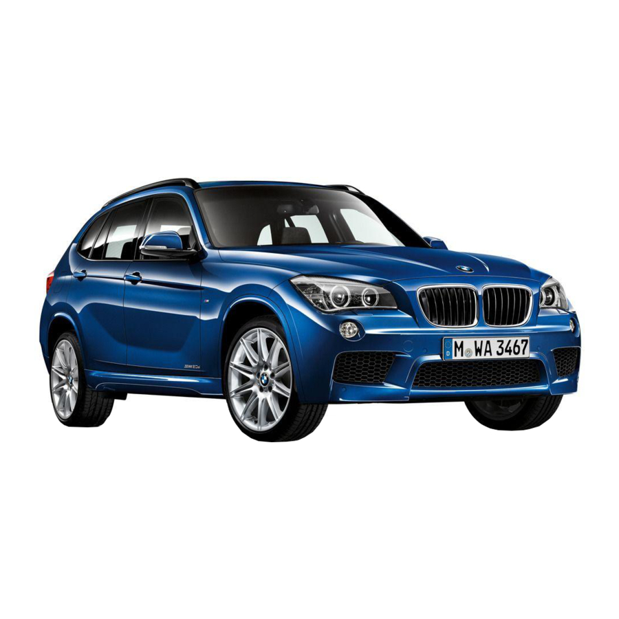
BMW X1.
LINK:
CONTENT & A-Z
Online Edition for Part no. 01405A1F038 — X/20
Other Manuals
- Handleiding – 356 pages
- Owner’s Manual – 352 pages
- Εγχειρίδιο χρήσης – 380 pages
- Omistajan käsikirja – 356 pages
- Bruksanvisning – 328 pages
- 17787
Книга по эксплуатации БМВ х1 в кузове F48 модель с 2016 года — второе поколение
Бмв х1 характеристики
Масса без груза (ЕС), кг [1,650]
Допустимая полная масса, кг [2,170]
Полезная нагрузка, кг 595
Допустимая нагрузка на оси (передняя/задняя), кг 1,150/1,075
Двигатель Количество цилиндров/клапанов на цилиндр 4/4
Рабочий объем, куб. см 1,995
Ход поршня / диаметр цилиндра, мм 90.0/84.0
Максимальная мощность, кВт (л. с.) при об/мин 170 (231)/4,400
Максимальный крутящий момент, Н•м при об/мин 450/1,500-3,000
Степень сжатия: 1 16.5
Ходовые качества Максимальная скорость, км/ч [235]
Время разгона 0–100 км/ч, с [6.6]
Расход топлива Городской цикл, л/100 км [6.1–5.9]
Загородный цикл, л/100 км [4.8–4.6]
Смешанный цикл, л/100 км [5.3–5.1]
Выброс CO2, г/км [139–134]
Объем топливного бака (прибл.), л 61
Колеса Размер передних шин 225/55 R17 97W
Размер задних шин 225/55 R17 97W
Размеры и материал исполнения 7,5 J x 17 дюймов, легкосплавные
Размеры и материал исполнения дисков задних колес 7,5 J x 17 дюймов, легкосплавные
Формат PDF
Автор BMW
БМВ х1 руководство
Добавлять комментарии могут только зарегистрированные пользователи.
[
Регистрация
|
Вход
]
Manufacturer: BMW, Model Year: 2016,
Model line: X1,
Model: BMW X1 2016 F48
Pages: 242, PDF Size: 7.12 MB
Trending: tire, Roof, TPMS, engine cover, Center armrest, service reset, Rear seats
Page 1 of 242

Page 2 of 242

Page 3 of 242

Page 4 of 242

Page 5 of 242

Page 6 of 242

Page 7 of 242

Page 8 of 242

Page 9 of 242

Page 10 of 242

- Load next 10 pages
Trending: wiper, power steering fluid, 5W-, water pump, dashboard, 0w 30, emergency
View, print and download for free: BMW X1 2016 F48 Owner’s Manual, 242 Pages, PDF Size: 7.12 MB. Search in BMW X1 2016 F48 Owner’s Manual online. CarManualsOnline.info is the largest online database of car user manuals. BMW X1 2016 F48 Owner’s Manual PDF Download.
All product names, logos, and brands are property of their respective owners.
Privacy Policy | About Us & Contact

Замена масла двигателя BMW
Срок службы масла в двигателе
Вне зависимости от того, какой двигатель в BMW (бензиновый или дизельный), рекомендованный срок службы масла истекает через год, или после 10 000 км пробега. необходимо учесть, что вне зависимости от того, насколько активно эксплуатировался автомобиль, по истечении г…

Замена цепи ГРМ в BMW
В автомобилях BMW привод ГРМ – цепной, расположен внутри двигателя. Такое оснащение, в сравнении с ремнем ГРМ отличается рядом преимуществ, но есть и недостатки. Из минусов можно выделить следующие:
• Из-за того, что цепь внутри двигателя, неисправность сложно диагностировать;
&bull…

Замена масла в двигателе N20 с последующим сбросом Oil Service
Для самостоятельной замены масла в моторе N20 в гаражных условиях нам понадобится комплект стандартных инструментов, само масло (лучше оригинал) и новый масляный фильтр — номер 11427640862 или 11427566327. Они абсолютно одинаковые, и различаются только наличием крышки в комплекте первого.
…

Правильно проверяем давление топлива в бензиновом ДВС
В этой статье расскажем о том, как проверить давление топлива в бензиновом впрысковом моторе, о проверке компонентов, как лучше найти причины неполадок и устранить их. Все, о чем пойдет речь дальше, взято не из пособий или мануалов, все советы основаны на личном опыте.
Один из ключевых моментов п…

Определяем, была ли машина битой или перекрашенной
Есть один прибор, невероятно простой и просто незаменимый при покупке подержанного автомобиля. С его помощью можно определить битая машина или нет, была ли перекрашена.
Устройство прибора предельно простое, не обязательно даже покупать, ведь такой индикатор можно сделать своими руками и довольно …

Как выбрать масло 0W-40?
На улице установилась капризная погода? Кажется, что не все ладно в природе? То солнце палит, то холод пробивает аж до мозга костей? Если человеку не совсем уютно, то, что тогда говорить об автотранспортном средстве. Что же пришло время поговорить о моторном масле. Как подобрать его? Как выбрать так…

Износ мотора. Все о самом важном агрегате
В июле 2012 г. было проведено исследование по заказу Castrol. Оно показало, что каждый заботливый автовладелец следит больше за двигателем, нежели за другими деталями автотранспортного средства. Он прикладывает все усилия, чтобы защитить его от всех неприятностей. Водители даже готовы отказаться от …
 :: BMW :: X1 серия :: F48")
- Самые активные участники сообщества
-

-
-
-
-
-
-
-
-
-
-
-
-
-
-
-
-
-
-
-
-
-
-
-
-
-
-


- Manuals
- Brands
- BMW Manuals
- Automobile
- X1 — PRODUCT CATALOGUE
- Owner’s handbook manual
-
Contents
-
Table of Contents
-
Bookmarks
Quick Links
Contents
A-Z
THE BMW X1.
OWNER’S HANDBOOK.
Online Edition for Part no. 01 40 2 964 279 — VI/15
Owner’s Handbook
for Vehicle
The Ultimate
Driving Machine
Related Manuals for BMW X1
Summary of Contents for BMW X1
-
Page 1
Contents Owner’s Handbook for Vehicle The Ultimate Driving Machine THE BMW X1. OWNER’S HANDBOOK. Online Edition for Part no. 01 40 2 964 279 — VI/15… -
Page 3
Please read the Owner’s Handbook before setting out in your new BMW. Also use the integrated Owner’s Handbook in your vehicle. It contains important notes on how to operate the vehi‐ cle, enabling you to derive maximum benefit from the technical advantages of your BMW. -
Page 4
© 2015 Bayerische Motoren Werke Aktiengesellschaft Munich, Germany Not to be reproduced, wholly or in part, without written permission from BMW AG, Munich. English VI/15, 07 15 490 Printed on environmentally friendly paper, bleached without chlorine, suitable for recycling. Online Edition for Part no. 01 40 2 964 279 — VI/15… -
Page 5: Table Of Contents
Contents Mobility For quick access to a particular topic or item, please consult the detailed alphabetical index, Refuelling see page 250. Fuel Wheels and tyres Engine compartment Notes Engine oil Coolant Overview Maintenance Cockpit Replacing parts iDrive Help in the event of a breakdown Voice control system General care Integrated Owner’s Handbook in the…
-
Page 6: Notes
Lists without a mandatory sequence or alter‐ questions. native possibilities are shown as a list with bul‐ Information on BMW, for example on technol‐ let points. ogy, on the Internet: www.bmw.com. ▷…
-
Page 7: Vehicle Equipment
Notes Vehicle equipment vehicles continue to embody the highest qual‐ ity and safety standards, we pursue a policy of This Owner’s Handbook describes all models continuous, ongoing development. Because and all standard, national and special equip‐ modifications in the design of both vehicles ment provided in the model series.
-
Page 8: Parts And Accessories
The manufacturer of your vehicle recommends ▷ Ambient conditions, for example, tempera‐ to consult with a BMW Service Partner prior to ture. purchasing spare parts, operating materials or This data is only of a technical nature and is for accessories.
-
Page 9: Vehicle Identification Number
Notes sonal in connection with other information, for example, accident report, damage to the vehi‐ cle, witness statements, etc. — possibly by en‐ listing the help of an expert. Additional functions, contractually agreed with the customer, for example vehicle location in an emergency, allow certain pieces of vehicle data to be transferred from the vehicle.
-
Page 10
Online Edition for Part no. 01 40 2 964 279 — VI/15… -
Page 11: Overview
Overview This summary of buttons, switches and displays serves as an initial guide. In addition, it gives you an insight into the principles behind the various ways in which functions can be performed. Online Edition for Part no. 01 40 2 964 279 — VI/15…
-
Page 12: Cockpit
Overview Cockpit Cockpit Vehicle equipment lected special equipment or national version. This also applies to safety-relevant functions This chapter describes all standard, national and systems. Comply with the relevant na‐ and special equipment provided in the model tional regulations when using the correspond‐ series.
-
Page 13
Cockpit Overview Low-beam headlights 102 Start/stop engine and switch igni‐ tion on/off 72 Automatic driving lights con‐ Auto Start Stop function 73 trol 103 Cornering light 104 11 Buttons on steering wheel, right High-beam assistance 105 Entertainment source Instrument lighting 106 Volume control Headlight beam throw adjust‐ ment 104 Voice control 25… -
Page 14
Overview Cockpit Queue assistant: Cruise Control 16 Unlock bonnet 209 distance 142 17 Opening the tailgate 38 Rocker switch for Cruise Con‐ trol 146, 136 Around the centre console Control Display 16 Parking brake 75 Ventilation 163 Dynamic Stability Control, DSC 130 Hazard warning lights 229 Drive experience switch 134 Intelligent Safety 117 Park Distance Control, PDC 148… -
Page 15
Cockpit Overview Around the headlining Intelligent emergency call 229 Interior light 106 Glass Roof 47 Front passenger airbag indicator lamp 110 Reading lights 106 Online Edition for Part no. 01 40 2 964 279 — VI/15… -
Page 16: Idrive
Overview iDrive iDrive Vehicle equipment Overview of controls This chapter describes all standard, national Control functions and special equipment provided in the model series. Equipment not available in the vehicle is therefore also described, for example the se‐ lected special equipment or national version. This also applies to safety-relevant functions and systems.
-
Page 17
iDrive Overview «Switch off control display» Tilting in four directions. Controller with navigation system Buttons on the Controller The buttons can be used to call up menus di‐ Press the but‐ Function rectly. The Controller can be used to select menu items and alter settings. -
Page 18
Overview iDrive Pressing. The main menu is displayed. All iDrive functions can be called up via the Tilting in four directions. main menu. Selecting a menu item Highlighted menu items can be selected. Turn the Controller until the desired menu item is highlighted. -
Page 19: Options Menu
iDrive Overview ▷ Tilt the Controller to the right. Turn the Controller until the desired set‐ ting is displayed. A new screen is opened and overlaid. Press the Controller. White arrows to the left or right indicate that other screens can be called up. Enabling/disabling functions Calling up the Options menu Some menu items are preceded by a check‐…
-
Page 20: Setting The Clock
Overview iDrive ▷ The system recognises capital and small touchpad. To do this swipe left or right as ap‐ letters. To enter small and capital letters propriate. and numbers, it may be necessary to the change input mode, for example, when Example: setting the clock identically writing small and capital letters.
-
Page 21: Other Functions
iDrive Overview Symbols for telephone Turn the Controller until «Time:» is high‐ lighted and press the Controller. Symbol Meaning Incoming or outgoing call. Missed call. Reception level of mobile telephone network. Symbol flashes: network search. No mobile telephone network avail‐ able.
-
Page 22
Overview iDrive Split-screen Favourites buttons General General In the split-screen view, additional information iDrive functions can be saved on the favourites can be displayed on the right-hand side of the buttons and called up directly, for example screen, for example information from the on- radio stations, navigation destinations, tele‐… -
Page 23
iDrive Overview Clearing assignment of buttons Deleting data Press buttons 1 and 8 simultaneously for Follow the instructions on the Control Display. approximately five seconds. Switch on ignition. «OK» «Settings» Calling up «Options». Deleting personal data in «Delete personal data» vehicle «Continue»… -
Page 24
Overview iDrive Entry comparison Input of names and addresses: the selection is gradually narrowed down and possibly supple‐ mented with every subsequent letter that you enter. Inputs are continuously compared with the data saved in the vehicle. ▷ Only letters that are present in the data is offered for entry. -
Page 25: Voice Control System
Voice control system Overview Voice control system Vehicle equipment Issuing voice commands This chapter describes all standard, national Activating the voice control system and special equipment provided in the model series. Equipment not available in the vehicle is Press the button on the steering therefore also described, for example the se‐…
-
Page 26: Adjusting Volume
Overview Voice control system If, for example, the menu «Settings» is dis‐ Press the button on the steering played, the commands for the settings are an‐ wheel. nounced. ›Sound‹ Running functions using short commands Setting the speech dialogue Main menu functions can be performed imme‐ diately using short commands, almost irre‐…
-
Page 27
Voice control system Overview could unnecessarily delay the connection of your call. Instead, use the SOS button, see page 229, in the area of the interior mirror. Operating conditions ▷ Commands, digits and letters should be pronounced fluently, with the usual em‐ phasis, and at a normal volume and speed. -
Page 28: Integrated Owner’s Handbook In The
Overview Integrated Owner’s Handbook in the vehicle Integrated Owner’s Handbook in the vehicle Vehicle equipment Owner’s Handbook Here, information and descriptions can be This chapter describes all standard, national searched via the index by directly entering a and special equipment provided in the model search term.
-
Page 29: Vehicle
Integrated Owner’s Handbook in the vehicle Overview Browse back. Press the button again to switch back to the last displayed function. Browse forward. Press the button again to switch back to the last displayed page of the Owner’s Handbook. Context-sensitive help — Owner’s To switch continuously between the last dis‐…
-
Page 30
Online Edition for Part no. 01 40 2 964 279 — VI/15… -
Page 31: Controls
Controls This chapter enables you to operate your car with greater ease, explaining in detail the features designed to make your journey safer, more comfortable and more enjoyable. Online Edition for Part no. 01 40 2 964 279 — VI/15…
-
Page 32: Opening And Closing
Controls Opening and closing Opening and closing Vehicle equipment Overview This chapter describes all standard, national and special equipment provided in the model series. Equipment not available in the vehicle is therefore also described, for example the se‐ lected special equipment or national version. This also applies to safety-relevant functions and systems.
-
Page 33
Opening and closing Controls Replacing the battery ▷ Inteference in radio transmission due to mobile radio device in the immediate vicin‐ ity of the remote control. ▷ Inteference in radio transmission due to the charger when charging in the vehicle, for example for mobile devices. -
Page 34: Profile Management
Controls Opening and closing Personal Profile ▷ Driver’s seat position, exterior mirror posi‐ tion, steering wheel position. Principle ▷ Cruise Control. Personal profile provides three profiles in ▷ Intelligent Safety. which personal vehicle settings can be saved. Each remote control is allocated to one of Profile management these profiles.
-
Page 35: With The Remote Control
USB interface: «USB device» Note Importing profiles WARNING Profiles exported via BMW Online can be im‐ Persons remaining in the vehicle or pets ported via BMW Online. left inside can lock the doors from the inside Profiles saved on a USB medium can be im‐…
-
Page 36: Courtesy Light
Controls Opening and closing Comfort closing ▷ The driver door and the fuel filler flap. ▷ All doors, the tailgate and the fuel filler flap. Keep the button on the remote control pressed after locking. The following functions are also carried out: ▷…
-
Page 37: From Outside
Opening and closing Controls Without remote control close opened tailgate, press and hold button of remote control until tailgate is closed. From outside Depending on the equipment and country ver‐ sion it can be set whether the doors are also WARNING locked.
-
Page 38
Controls Opening and closing Tailgate Alarm system is triggered if the vehicle has been unlocked using the door lock. Notes To end this alarm, unlock the vehicle with the remote control or turn on the ignition, with To prevent the remote control from being special ID of the remote control, see page 33, locked in, do not place the remote control in as necessary. -
Page 39
Opening and closing Controls Opening ATTENTION Sharp or angular objects can hit the rear ATTENTION window and the heating conductor during the The tailgate swings rearwards and up‐ journey. Danger of damage to property. Cover wards when opened. Danger of damage to the edges and make sure that sharp objects property. -
Page 40
Controls Opening and closing ATTENTION Pressing the button again stops the move‐ ment. Sharp or angular objects can hit the rear window and the heating conductor during the journey. Danger of damage to property. Cover the edges and make sure that sharp objects cannot strike the rear window.◀… -
Page 41
Opening and closing Controls Comfort Access Unlocking Principle Access to the vehicle is possible without acti‐ vating the remote control. It is sufficient to have the remote control with you, for example in a trouser pocket. The vehicle automatically recognises the re‐ mote control when it is in the immediate vicin‐… -
Page 42
Controls Opening and closing Foot movement to be undertaken WARNING During operation without contact, there is a risk of touching vehicle parts, for example the hot exhaust system. Danger of injury. Make sure you are standing securely when you per‐ form the foot movement, and do not touch the vehicle.◀… -
Page 43
Opening and closing Controls Malfunction WARNING Operating the tailgate can lead to parts of Detection of the remote control by the vehicle the body becoming trapped. Danger of injury. may be disrupted by the following circumstan‐ When opening and closing, make sure that the ces, amongst others: area of movement of the tailgate is free.◀… -
Page 44
Controls Opening and closing Boot lid When the vehicle is unlocked, this position is called up automatically if the function has been Depending on the equipment and country ver‐ enabled. sion, these settings are not provided. WARNING «Settings» Danger of trapping when moving the «Doors/key»… -
Page 45: Switching Off The Alarm
Opening and closing Controls Arming and disarming ▷ The indicator light flashes after unlocking until the ignition is switched on, but for no At the same time as unlocking and locking the longer than approximately five minutes: vehicle by remote control or Comfort Access the alarm system is also disarmed or armed.
-
Page 46: Power Windows
Controls Opening and closing ▷ For Comfort Access: completely grasp ei‐ The window opens automatically. The ther front door handle when carrying re‐ movement is stopped by pressing the mote control. switch again. See also: Comfort opening, see page 36, by remote control.
-
Page 47: Panorama Glass Roof
Opening and closing Controls Notes WARNING Accessories on the windows, for exam‐ WARNING ple aerials, can impair the anti-trap mecha‐ Operating the windows can lead to parts nism. Danger of injury. Do not attach any ac‐ of the body or objects becoming trapped. Dan‐ cessories in the area of movement of the ger of injury or damage to property.
-
Page 48
Controls Opening and closing WARNING closed or is in the raised po‐ sition, the sun blind closes. Unsupervised children or animals in the vehicle can set the vehicle in motion and en‐ ▷ Push the switch beyond the resistance danger themselves or other road users, for ex‐ point in the desired direction. -
Page 49
Opening and closing Controls Anti-trap mechanism Initialising the system If the closing power of the Glass Roof exceeds The system can be initialised when the vehicle a certain value, the closing operation is inter‐ is stationary and the engine is running. rupted from approximately the half-open posi‐… -
Page 50: Adjusting
Controls Adjusting Adjusting Vehicle equipment backrest in the most upright possible position, and do not change it during the journey.◀ This chapter describes all standard, national WARNING and special equipment provided in the model series. Equipment not available in the vehicle is Danger of trapping when moving the therefore also described, for example the se‐…
-
Page 51
Adjusting Controls Forward/back Seat angle Pull the lever and slide the seat in the desired Pull lever up or press lever down until the de‐ direction. sired seat angle is reached. After releasing the lever, move the seat gently forward or back to make sure it engages prop‐ Electrically adjustable seats erly. -
Page 52: Lumbar Support
Controls Adjusting Settings in detail Thigh support Longitudinal direction. Pull the lever on the front of the seat and adjust the thigh support. Height. Lumbar support The curvature of the backrest can be changed in such a way that the lumbar region, the lordo‐ sis, is supported.
-
Page 53: Rear Seats
Adjusting Controls Seat heating, front cidents. Only adjust the seat on the driver side when at a standstill.◀ Forward/back Switching on Press the button once per tempera‐ ture stage. Pull the lever and slide the seat in the desired direction. Maximum temperature is indicated by three LEDs.
-
Page 54
Controls Adjusting Seat belts pants have fastened their seat belts cor‐ rectly.◀ Number of seat belts WARNING Your vehicle has been fitted with five seat belts Seat belts are designed to bear upon the for the safety of you and your passengers. bony structure of the body and should be worn However, they can only offer protection when low across the front of the pelvis, or the pelvis,… -
Page 55
Adjusting Controls Correct seat belt use Unfastening the seat belt ▷ Place the seat belt tightly over the pelvis Hold onto the belt. and shoulder as close as possible to the Press the red button on the belt buckle. body and without twisting. Guide the belt back up to the reel mecha‐… -
Page 56
Controls Adjusting Seat belt reminder for driver’s and clean. After an accident, have the seat belts in‐ front seat passenger seat spected at a Service Partner or a qualified spe‐ cialist workshop.◀ A Check Control message is displayed. Check whether the seat belt has been In the event of stress due to an accident or fastened correctly. -
Page 57: Rear Head Restraints
Adjusting Controls Rear head restraints Height Adjust the head restraint so that its centre is Notes approximately at the height of your ear. WARNING Spacing Head and neck injuries can result due to Adjust the spacing so that the head restraint is the lack of protective effect if head restraints as close as possible to the back of the head.
-
Page 58: Seat And Mirror Memory
Controls Adjusting Adjusting height WARNING Danger of trapping when moving the seats. Danger of injury or damage to property. Before making the setting, make sure that the movement area of the seat is clear.◀ Principle Two different positions for driver’s seat and exterior mirrors can be saved and recalled per profile.
-
Page 59
Adjusting Controls Convenience function estimated, for example when changing lane. Danger of accidents. Look over your shoulder Open the driver’s door. to estimate the distance from following traf‐ Switch ignition off if necessary. fic.◀ Briefly press button 1 or 2 as desired. The relevant seat adjustment is done automat‐… -
Page 60
Controls Adjusting Rear-view mirror, manual-dim cles near the ground, for example when park‐ ing. Turn button Activating Push switch to driver’s mirror posi‐ tion. Engage selector lever position R. Deactivating Push switch to front passenger’s mirror posi‐ tion. To reduce glare by turning the button on the Folding in and out rear-view mirror. -
Page 61
Adjusting Controls Steering wheel Steering wheel heating Note WARNING Steering wheel adjustment during the journey can lead to unexpected steering wheel movements. You could lose control of the vehi‐ cle. Danger of accidents. Only adjust the steer‐ ing wheel when the vehicle is at a standstill.◀ Press the button. -
Page 62: Carrying Children In Safety
Controls Carrying children in safety Carrying children in safety Vehicle equipment lected special equipment or national version. This also applies to safety-relevant functions This chapter describes all standard, national and systems. Comply with the relevant na‐ and special equipment provided in the model tional regulations when using the correspond‐…
-
Page 63
Carrying children in safety Controls Group Weight of child Approximate Front pas‐ Rear seats, Rear seat, senger’s seat outer – b) middle 22 – 36 kg 7 years or more U: suitable for child restraint systems in Universal category that have been approved for use in this weight group. -
Page 64: Before Installation
Controls Carrying children in safety Before installation airbag for the front passenger’s seat that can‐ not be deactivated: Make sure backrests are engaged before fit‐ ting child restraints. It is recommended not to use any kind of child restraint system on the front Move rear seats to rearmost position to make it passenger’s seat.
-
Page 65
Carrying children in safety Controls to the rear and as far up as possible to achieve the best possible routing of the belt and pro‐ tection in the event of an accident. If the upper attachment point of the seat belt is located ahead of the child seat’s belt guide, carefully move the front passenger’s seat for‐… -
Page 66
Controls Carrying children in safety Group Weight of Approxi‐ Class/category Front pas‐ Rear seats, Rear seat, child mate age senger’s outer middle seat – b) 9 — 18 kg D — ISO/R2 to 4 years C — ISO/R3 D — ISO/R2, a) IL, IUF IL, IUF C — ISO/R3, a) -
Page 67
Carrying children in safety Controls Not for Australia/New Zealand: front Note passenger seat ATTENTION The mounting points for the upper re‐ taining straps of child restraint systems are only intended for these retaining straps. The mounting points can be damaged if other ob‐ jects are attached. -
Page 68
Controls Carrying children in safety Engage the hook of the retaining strap in WARNING the mounting point. In the event of an accident, persons sit‐ Pull the restraining strap firmly down. ting in the rear can come in contact with the tensioned retaining strap of the child restraint Push head restraint down if necessary and system on the front passenger seat. -
Page 69
Carrying children in safety Controls For Australia/New Zealand: Guiding the retaining strap Child restraints WARNING If the upper retaining strap is used incor‐ Information rectly with the child restraint system, the pro‐ In accordance with ADR 34/01, provisions tective effect may be reduced. Danger of in‐ have been made to allow installation of a child jury. -
Page 70: Rear Doors
Controls Carrying children in safety Securing doors and windows in the rear Rear doors Not for Australia/New Zealand — Front passenger seat: guide the upper retain‐ ing strap between the brackets of the head re‐ straints of the front passenger seat and rear seat on the front passenger side.
-
Page 71: Driving
Driving Controls Driving Vehicle equipment Ignition off Steptronic transmission: Press the start/stop This chapter describes all standard, national button again without applying the brakes. and special equipment provided in the model Manual gearbox: Press the start/stop button series. Equipment not available in the vehicle is again, do not press the clutch pedal.
-
Page 72: Diesel Engine
Controls Driving ▷ Shortly before the battery is discharged so ▷ Additionally secure the vehicle on upward that an engine start remains possible. or downward gradients, e.g. using a wedge.◀ Radio readiness remains active when ignition is switched off automatically, such as for ATTENTION following reasons: Repeated start attempts or starting sev‐…
-
Page 73
Driving Controls Stopping the engine Steptronic transmission Stopping the engine Notes With vehicle at a standstill, engage selector WARNING lever position P. Unsupervised children or animals in the Press the start/stop button. vehicle can set the vehicle in motion and en‐ The engine is switched off. -
Page 74
Controls Driving ▷ Driver’s seat belt buckled or driver’s door ▷ Condensation when the automatic air con‐ closed. ditioning is switched on. To be able to release the brake pedal when the ▷ Vehicle battery is heavily discharged. vehicle is stationary, engage the selector lever ▷… -
Page 75: Automatic Deactivation
Driving Controls Parking the vehicle during automatic ▷ Steptronic transmission: shift from selector engine stop lever position D to N, R or M/S. ▷ Steptronic transmission: shift from selector With automatic engine stop, the vehicle can be lever position P to N, D, R or M/S. parked safely, for example in order to leave it.
-
Page 76
Controls Driving Overview Risk of accident or injury. Do not leave children or animals unsupervised in the vehicle. When leaving the vehicle, take the remote control with you and lock it.◀ Pull switch. LED is illuminated. The indicator light illuminates red. The parking brake is engaged. -
Page 77: Initial Operation
Driving Controls Automatic release with Steptronic The indicator light in the instrument transmission cluster extinguishes when the parking brake is operational again. Operate the accelerator pedal to automatically release. LED and indicator light turn off. Turn indicators, high-beam Under the following conditions, the parking headlights, headlight flasher brake is automatically released by operating the accelerator pedal.
-
Page 78: Wiper System
Controls Driving Notes The setting is saved for the currently used pro‐ file. ATTENTION If the wipers have frozen on, switching on Indicating a turn briefly can cause the wiper blades to tear and the Press the lever as far as the resistance point wiper motor to overheat.
-
Page 79
Driving Controls Switching off and flick-wiping ATTENTION In car washes, the wipers may inadver‐ tently start moving if the rain sensor is activa‐ ted. Danger of damage to property. Deactivate the rain sensor in car washes.◀ Setting the interval time or sensitivity of the rain sensor The lever returns to the basic position when released. -
Page 80: Rear Window Wiper
Controls Driving washer systems if there is no possibility of the WARNING washer fluid freezing. Use anti-freeze if re‐ If the wipers start moving when they are quired.◀ folded away from the windscreen, this can damage parts of the vehicle, or trap body parts. ATTENTION Danger of injury or damage to property.
-
Page 81: Selector Lever Positions
Driving Controls Reverse gear out by a Service Partner or a qualified special‐ ist workshop.◀ Engage this position only when the vehicle is stationary. Reservoir for washer fluid To overcome the resistance of the selector lever move in a dynamic movement towards the left and engage the reverse gear.
-
Page 82
Controls Driving Activating M/S manual operation The selector lever can only be taken out of the selector lever position P with the ignition Press the selector lever out of selector switched on or the engine running. lever position D to the left. When the vehicle is stationary, press the brake Pull the selector lever forwards or back‐… -
Page 83: Manual Operation
Driving Controls the same time allows you to change down to ▷ Give right shift paddle a long pull. the lowest possible gear. However, this behav‐ iour does not apply if there is a brief change ▷ In addition to briefly pulling right shift pad‐ from selector lever position D to manual opera‐…
-
Page 84
Controls Driving Move the selector lever back slightly, by Depress the brake forcefully with your foot. pressing on the unlock button on the front Press the accelerator pedal down beyond of the selector lever. the resistance at the full-throttle position Release the release lever. -
Page 85: Displays
Displays Controls Displays Vehicle equipment lected special equipment or national version. This also applies to safety-relevant functions This chapter describes all standard, national and systems. Comply with the relevant na‐ and special equipment provided in the model tional regulations when using the correspond‐ series.
-
Page 86: Check Control
Controls Displays Red lights ▷ Seat belt reminder for rear seats, see page 56. Seat belt reminder ▷ Kilometres/trip odometer, see page 90. Seat belt is not fastened on the driver’s ▷ Messages, for example Check Control, see side. For some country versions: front page 86.
-
Page 87
Displays Controls Yellow lights Front-end collision warning Illuminating: forewarning, for example if Anti-lock Brake System, ABS a danger of collision is anticipated or there is a very short distance to a vehi‐ Avoid abrupt braking if possible. Brak‐ cle ahead. ing force reinforcement faulty. -
Page 88
Controls Displays Tyre Pressure Monitor TPM Lane departure warning Illuminating: the Tyre Pressure Monitor System is switched on and warns you reports a pressure loss in a tyre. under certain conditions if you leave a detected lane without indicating first. Reduce your speed and carefully stop the vehicle. -
Page 89: Text Messages
Displays Controls Symbols High-beam assistance Inside the extended text message, depending High-beam assistance is switched on. on the Check Control message, the following High-beam headlights are switched on functions can be selected. and off automatically depending on the ▷ Display additional information on the traffic situation.
-
Page 90: Outside Temperature
Controls Displays Displaying Check Control messages Show/reset distance saved in memory Press the button. On the Control Display: ▷ When the ignition is off, the time, outside temperature «Vehicle information» and odometer are displayed. «Vehicle status» ▷ When the ignition is on, the «Check Control»…
-
Page 91: Service Requirements
Displays Controls Range Displaying the current fuel consumption Display Depending on equipment, the current fuel con‐ sumption can be shown as a bar display in the If there is a small remaining instrument cluster. range: «Settings» ▷ A Check Control message is briefly displayed.
-
Page 92
Controls Displays Essential maintenance routines and any On the Control Display: statutory inspections required are dis‐ «Vehicle information» played. «Vehicle status» Select an entry to display more detailed in‐ Call up «Options». formation. «Last Teleservice Call» Symbols Service history Sym‐ Description bols General… -
Page 93
Displays Controls Shift point indicator Speed Limit Information with No Passing Information Principle Principle The system recommends the most efficient gear for the current driving situation. Speed Limit Information General The currently detected speed limit is displayed by Speed Limit Information using a symbol in The shift point indicator is active in the manual the shape of a traffic sign in the instrument mode of the Steptronic transmission and man‐… -
Page 94
Controls Displays Notes Display Speed limits and no overtaking for towing a The following appears in the instrument clus‐ trailer are not shown. ter: WARNING Speed Limit Information The system does not take your personal Last detected speed limit. responsibility from you when you are estimat‐ ing the visibility conditions and traffic situation. -
Page 95
Displays Controls Display ▷ When the windscreen in front of the rear- view mirror is covered with condensation, dirt, stickers, labels, etc. ▷ Due to possible wrong detections of the camera. ▷ If the speed limits saved in the navigation system are wrong. -
Page 96
Controls Displays On-board computer Setting displays for the information display Calling up information on the Depending on the equipment, it can be set information display which displays of the on-board computer can be called up on the information display in the instrument cluster. -
Page 97
Displays Controls Resetting average values Journey computer Two types of on-board computer are available. ▷ «On-board computer»: values can be reset any number of times. ▷ «Trip computer»: values deliver an over‐ view of the current trip. Resetting the Journey computer On the Control Display: «Vehicle information»… -
Page 98
Controls Displays Speed warning Sports instruments Values for performance and torque are shown Principle on the control display. Display of a speed at which a warning is to be Show sports instruments issued when reached. Via iDrive: Repeat warning if the set speed limit was un‐ dershot once by at least 5 km/h/3 mph. -
Page 99
Displays Controls Settings on the Control Date Display Setting the date «Settings» Time «Time/date» Setting the time zone «Date:» «Settings» Turn the controller until the desired day is «Time/date» displayed. «Time zone:» Press the controller. Select desired time zone. Make the setting for month and year ac‐ cordingly. -
Page 100
Controls Displays Head-Up Display Units of measure Setting the units of measure Overview To set the units of measure for fuel consump‐ tion, distance covered/remaining range, and temperature: «Settings» «Language/units» Select the desired menu item. Select the desired unit. The setting is stored for the currently used profile. -
Page 101
Displays Controls Display Adjusting height On the Control Display: Overview «Settings» The following information is displayed in the «Head-up display» Head-Up Display: «Height» ▷ Speed. Turn the Controller until the desired height ▷ Navigation system. is obtained. ▷ Check Control messages. Press the Controller. -
Page 102: Lights
Controls Lights Lights Vehicle equipment Symbol Function This chapter describes all standard, national Lights off and special equipment provided in the model Automatic driving lights control series. Equipment not available in the vehicle is Daytime driving lights therefore also described, for example the se‐ lected special equipment or national version.
-
Page 103: Parking Lights
Lights Controls The low-beam headlights illuminate with the The setting is saved for the currently used pro‐ ignition switched on. file. Parking lights Headlight courtesy delay feature If the headlight flasher is activated after switch‐ ing off the radio ready state, the low-beam headlights illuminate and remain on for a cer‐…
-
Page 104: Daytime Driving Lights
Controls Lights System limits The variable light distribution enables better il‐ lumination of the carriageway, depending on The automatic driving lights control is no sub‐ speed. stitute for your individual judgement of when it is necessary to switch on the lights. ▷…
-
Page 105
Lights Controls High-beam assistance Raising and dipping manually Principle When low-beam headlights are switched on, this system automatically switches the high- beam headlights on and off. This process is controlled by a camera on the front of the rear- view mirror. It ensures that the high-beam headlights are switched on whenever the traf‐… -
Page 106
Controls Lights Halogen headlights ▷ When the windscreen in front of the rear- view mirror is covered with condensation, The Service Partner or a qualified specialist dirt, stickers, labels, etc. workshop has light benders available. Proceed in accordance with the enclosed information when affixing the light benders to the head‐… -
Page 107: Reading Lights
Lights Controls Overview Adjusting brightness Via iDrive: «Settings» «Lights» «Brightness:» Adjusting brightness. Interior light Reading light Switching the interior light on and off manually Press the button. To switch off permanently: press the button for approximately three seconds. Switch on again: press button. Reading lights Press the button.
-
Page 108: Security
Controls Security Security Vehicle equipment lected special equipment or national version. This also applies to safety-relevant functions This chapter describes all standard, national and systems. Comply with the relevant na‐ and special equipment provided in the model tional regulations when using the correspond‐ series.
-
Page 109
Security Controls Notes on optimum protective effect of ▷ Do not dismantle the airbag system. the airbag Even if all these notes are complied with, de‐ pending on the circumstances in which an ac‐ WARNING cident occurs, certain injuries as a result of If the seat position is wrong or the de‐… -
Page 110
Controls Security Not for Australia/New Zealand: Key Activating the front passenger airbags switch for front passenger airbags General Insert the key and press inwards where necessary. While the key is pressed inwards, turn it to the ON position as far as it will go. Once the stop position has been reached, re‐… -
Page 111
Security Controls Depending on the equipment version, different WARNING indicator lights may illuminate. Changes to the pedestrian protection system can lead to a failure, a malfunction or Display Function accidental triggering of the pedestrian protec‐ If the front passenger airbag is tion system. -
Page 112
Controls Security After triggering or if the system is damaged, Reset the system after adjusting the tyre pres‐ have it checked and replaced at a Service Part‐ sure to a new value and after a tyre or wheel ner or in a qualified specialist workshop.◀ change. -
Page 113
Security Controls Running reset The symbol identifying run-flat tyres, see page 203, is the circle with the letters RSC Reset the TPM after adjusting the tyre inflation on the tyre side wall. pressure to a new value and after a tyre or wheel change. -
Page 114
Controls Security Run-flat tyres WARNING A damaged tyre with run-flat properties Top speed with low or missing tyre inflation pressure will If a tyre has punctured you can continue your change the driving properties, for example re‐ journey, driving at speeds up to a maximum of duced directional stability when braking, lon‐… -
Page 115
Security Controls Runflat indicator RPA ▷ Check the tyre pressure and adjust as nec‐ essary. Principle ▷ Reset the system after a wheel change. The system identifies a loss of tyre pressure System limits by comparing the speeds of rotation of the in‐ dividual wheels while the vehicle is in motion. -
Page 116
Controls Security Start the engine – do not drive off. No warning can be given in the event of sud‐ den tyre failure caused by external factors. Start initialisation: «Perform reset». In the following situations, the system could be Drive off. slow to respond or operate incorrectly: Initialising is completed during the journey;… -
Page 117
Security Controls Do not exceed a speed of 80 km/h, 50 mph When driving with a trailer and a flat tyre, do any longer. not exceed the speed of 60 km/h, approxi‐ mately 35 mph. As soon as you get an opportunity, check the tyre pressure in all four tyres. -
Page 118
Controls Security WARNING ▷ All Intelligent Safety Systems are switched Due to system limitations, there may be malfunctions of individual functions when tow- ▷ LED is illuminated green. starting/towing with activated Intelligent Safety Press and hold down the button: Systems, for example approach control warn‐ ing with light braking function. -
Page 119
Security Controls Detection range Overview Button in the vehicle Objects are taken into account if they are de‐ tected by the system. Intelligent Safety button Notes WARNING Camera Displays and warnings do not take your personal responsibility from you. System limi‐ tations can mean that warnings or system re‐… -
Page 120
Controls Security ▷ LED illuminates orange or goes out, de‐ Symbol Measure pending on individual setting. Symbol illuminates red: advance Press the button twice if necessary to switch warning. off the front-end collision warning. Increase braking and distance. Settings are made. The individual settings are saved for the currently used profile. -
Page 121
Security Controls Sensitivity of the warnings There will only be brake intervention if Dy‐ namic Stability Control, DSC is activated. The greater the sensitivity of the warning set‐ Braking can be discontinued either by pressing tings, for example warning time, the more the accelerator pedal or by actively moving the warnings will be displayed. -
Page 122
Controls Security Camera ▷ Central zone, arrow 1, directly in front of the vehicle. ▷ Extended zone, arrow 2, at right and left. There is a risk of collision if persons are in the central zone. A warning is only given of per‐ sons in the extended zone if they are moving in the direction of the central zone. -
Page 123: Lane Departure Warning
Security Controls ▷ LED turns off. It is possible that the following are not detec‐ ted: ▷ Partially concealed pedestrians. Warning with braking function ▷ Pedestrians who are not detected as such Display because of the viewing angle or contour. If there is a risk of collision with a detected per‐…
-
Page 124
Controls Security warning may vary depending on the current Keep the windscreen clean and clear in the driving situation. area in front of the rear view mirror. The system does not issue a warning if the driver indicates before leaving the driving lane. Switching on/off Information Automatic activation… -
Page 125
Security Controls Manual speed limiter Output of the warning If the vehicle leaves the driving lane and a lane Principle marking is detected, the steering wheel starts to vibrate. With the system, the speed can be restricted from a value of 30 km/h/20 mph. There are no If the turn indicator is set before changing restrictions below the set speed limit. -
Page 126
Controls Security When switching on when at a standstill rolls until the driving speed drops below the 30 km/h/20 mph is set as the speed limit. speed limit. The speedometer marker is set to the corre‐ Exceeding the speed limit sponding speed. -
Page 127
Security Controls Indicator light Using Speed Limit Assist ▷ If the indicator light is illuminated: the system is switched on. ▷ If the indicator light is flashing: set speed limit is exceeded. Brief status display Set speed limit briefly appears. If the Speed Limit Information system detects a change in the speed limit on the route, a Speed Limit Assist… -
Page 128
Controls Security Dynamic brake lights After the start of the drive, the system is adap‐ ted to the driver so that an increase in inatten‐ tion or fatigue can be detected. Principle This process considers the following criteria: ▷ Personal driving style, for example, steer‐ ing. -
Page 129
Security Controls of a further collision and its consequences can thereby be reduced. By depressing the brake pedal, the vehicle can be decelerated much faster. The automatic braking is interrupted as a result. By pressing the accelerator pedal, automatic braking is also interrupted. -
Page 130: Driving Stability Control Systems
Controls Driving stability control systems Driving stability control systems Vehicle equipment spin, for example on loose ground and auto‐ matically brakes this. This chapter describes all standard, national The drive force is diverted to the wheel with and special equipment provided in the model better traction.
-
Page 131
Driving stability control systems Controls Overview Indicator and warning lights DSC OFF is displayed in the instrument cluster Button in the vehicle when DSC is deactivated. If indicator light is illuminated: DSC is deactivated. Automatic activation With DSC deactivated, there is automatic acti‐ vation in the following situations: ▷… -
Page 132
Controls Driving stability control systems Deactivating/activating Dynamic approximately more than walking speed, with‐ Traction Control, DTC out the driver braking. HDC can be activated under approximately Activating DTC 35 km/h, approximately 22 mph. When driving downhill, the vehicle reduces the speed to ap‐ Press the button. -
Page 133
Driving stability control systems Controls Programs backwards, it is reduced to approximately 6 km/h, 4 mph. The system provides different programs. The progams can be selected via the Drive ex‐ Activating HDC perience, see page 134. SPORT Resolute sports configuration of the shock ab‐ sorbers for greater agility when driving. -
Page 134
Controls Driving stability control systems Drive experience switch Configuring SPORT If display on Control Display is activated, Principle SPORT can be configured individually. With the drive experience switch, certain prop‐ Activating SPORT. erties of the vehicle can be adjusted. Various Select «Configure SPORT». -
Page 135
Driving stability control systems Controls Drive-off assistant Via iDrive «Settings» The system provides support when driving off «ECO PRO mode» on upward inclines. It is not necessary to use the parking brake for this. Hold the vehicle in place by pressing the «Settings»… -
Page 136: Driving Comfort
Controls Driving comfort Driving comfort Vehicle equipment corresponding button to reactivate system. Vehicle is accelerated again. This chapter describes all standard, national As soon as the road in front of you is clear, the and special equipment provided in the model vehicle accelerates to your desired speed.
-
Page 137
Driving comfort Controls Overview Keep the windscreen clean and clear in the area in front of the rear-view mirror. Buttons on the steering wheel Switching the Cruise Control on/off Press the Function and interrupting button Switching on Cruise Control on/off, interrupt, see page 137. -
Page 138
Controls Driving comfort Maintaining speed, saving ▷ If the vehicle is stationary and the seat belt and driver’s door are opened. ▷ If the detection zone of the camera is dis‐ rupted, for example, due to dirt, heavy rain‐ fall or dazzling by the sun. ▷… -
Page 139
Driving comfort Controls When the vehicle is at a standstill Danger of accident or damage to property. Ob‐ serve the traffic conditions attentively at all The vehicle was braked to a complete stop by times. Adapt the distance to traffic and the system: weather conditions, and comply with the pre‐… -
Page 140
Controls Driving comfort With queue assistant: press and hold Distance indicator the button. Distance 3 The indicator light in the instrument Automatically set after switching on cluster is illuminated. the system. Corresponds to approxi‐ mately half of the value in the speed‐ To switch back to Cruise Control with distance ometer display, expressed in metres. -
Page 141
Driving comfort Controls Displays on the Head-Up Display Deceleration Some information from the system can also be The system does not decelerate in the shown on Head-Up Display. following situations: ▷ Pedestrians, cyclists or similar slow road System limits users. ▷… -
Page 142
Controls Driving comfort Cornering In such cases, press accelerator pedal. Weather In unfavourable weather or light conditions, for example during rain, snow, slush, fog or on‐ coming glare, detection of vehicles may deteri‐ orate and there may be brief interruptions of al‐ ready detected vehicles. -
Page 143
Driving comfort Controls Functional requirements dependent on speed for safety reasons. To maintain distance, the system automatically ▷ Driving on an approved type of road. The reduces speed, brakes slightly if necessary, data on this is laid down in the navigation and accelerates again when the vehicle in front system. -
Page 144
Controls Driving comfort The display is no longer illuminated. Set de‐ sired speed and distance continue to be held by ACC. The system does not make any steering move‐ ment. Interrupting When the system is activated, press the button. The camera is in the area of the base of the rear-view mirror. -
Page 145
Driving comfort Controls Queue assistant is interrupted. The system Distance indicator does not make any steering movement. ACC Distance 3 controls. Set after switching on the system. If the system conditions are met, the system is Corresponds to approximately half of reactivated automatically. -
Page 146: Cruise Control
Controls Driving comfort Cruise Control Symbol Description Rolling bars while the vehicle is in Principle motion: speed is no longer in‐ System keeps to speed set using buttons on creased by the queue assistant at steering wheel. On downhill gradients, the sys‐ 60 km/h/35 mph.
-
Page 147
Driving comfort Controls Controls ▷ If Dynamic Traction Control is activated or DSC is disabled. Switching on ▷ If DSC intervenes. Press the button on the steering ▷ If HDC is activated. wheel. Maintaining, saving, changing speed The speedometer marker is set to the current speed. -
Page 148
Controls Driving comfort Brief status display sired speed is increased or decreased by approximately 1 km/h, 1 mph. Selected desired speed. ▷ Each time the rocker switch is pressed be‐ yond the resistance point, the desired speed is increased or decreased to the If no speed is displayed, the conditions re‐… -
Page 149
Driving comfort Controls Switching on/off accidents. Adapt driving style to the driving conditions. Observe the traffic situation and in‐ Automatic switching on tervene actively if the situation warrants it.◀ PDC switches on automatically in the following WARNING situations: If the vehicle is travelling at high speed ▷… -
Page 150: Volume Control
Controls Driving comfort stance, if an object is identified to the rear left «Rear view camera» of the vehicle, the warning signal sounds from System limits the rear left loudspeaker. The shorter the distance to an object be‐ With a trailer or when the trailer comes, the shorter the intervals become.
-
Page 151
Driving comfort Controls False alarms Notes Under the following conditions, PDC can issue WARNING a warning although there is no obstacle in the The system does not take your personal detection range: responsibility from you when you are estimat‐ ▷ In heavy rain. -
Page 152
Controls Driving comfort Switching on/off Driving lane and turning circle lines are dis‐ played. Automatic activation ▷ Obstacle marking. While the engine is running, engage selector «Obstacle marking» lever position R. Spatially shaped markings are displayed. ▷ Trailer tow hitch Automatic switching off when moving forwards «Towbar zoom»… -
Page 153: Display Settings
Driving comfort Controls The turning circle lines show the course of the Displaying the trailer tow hitch via iDrive, see smallest possible turning circle on a level road page 152. surface. When the steering wheel is turned to a certain Parking with the help of driving lane extent, only a turning circle line is shown.
-
Page 154
Controls Driving comfort Notes Turn the controller until the desired setting is reached and press the controller. WARNING The system does not take your personal System limits responsibility from you when you are estimat‐ ing the traffic situation. Due to limits of the sys‐ Detection of objects tem, it cannot respond independently in a rea‐… -
Page 155
Driving comfort Controls Ultrasonic sensors ▷ You must indicate accordingly when park‐ ing into parking spaces on the driver’s side. Switching on/off Switching on with the button Press the button. LED is illuminated. The current status of the parking space search is displayed on the Control Display. -
Page 156
Controls Driving comfort Status of the system Follow the instructions on the display. To achieve an optimum parking position, wait for the automatic steering process af‐ ter changing gear at standstill. The end of the parking process is dis‐ played on the display. Straighten up the parking position, if appli‐… -
Page 157
Driving comfort Controls System limits ▷ For objects with corners and sharp edges. ▷ For objects with fine surfaces or struc‐ No parking support tures, for example fences. The Park Assistant does not support in the ▷ For objects with porous surfaces. following situations: Low objects already indicated, such as kerbs, ▷… -
Page 158: Climate
Controls Climate Climate Vehicle equipment lected special equipment or national version. This also applies to safety-relevant functions This chapter describes all standard, national and systems. Comply with the relevant na‐ and special equipment provided in the model tional regulations when using the correspond‐ series.
-
Page 159
Climate Controls Switching off In the event of condensation, switch off the re‐ circulated-air mode and increase the air flow if Hold down left button until the control necessary. shuts down. Adjusting the air flow manually Temperature Pressing the button on the left or right Turn the wheel to select the de‐… -
Page 160: Automatic Air Conditioning
Controls Climate This filter should be changed during mainte‐ nance on your vehicle, see page 216. Automatic air conditioning Defrosting windows and removing conden‐ Temperature, right sation 10 Cooling function Temperature, left 11 AUC/recirculated-air mode AUTO program 12 Seat heating, right 53 Switching the system off 13 Air distribution…
-
Page 161
Climate Controls Temperature The function is available through an outside temperature of approximately 0 ℃/32 ℉ and Turn the wheel to select the de‐ with the engine running. sired temperature. The air flow can be adapted when the program is active. AUTO program The selected temperature is shown on the dis‐… -
Page 162
Controls Climate ▷ Left-hand LED on, AUC mode: a sensor If there is condensation on the window, press detects pollutants in the outside air and the AUTO button in order to use the conden‐ shuts it out automatically. sation sensor. ▷… -
Page 163: Independent Ventilation
Climate Controls Ventilation Independent ventilation Ventilation at front Principle The independent ventilation system ventilates the passenger compartment and lowers its temperature under some circumstances. The system can be switched on and off at any ambient temperature either directly or via two preselected switch-on times.
-
Page 164
Controls Climate The system switches on within the next 24 hours only. Afterwards, it must be reactiva‐ ted. Online Edition for Part no. 01 40 2 964 279 — VI/15… -
Page 165: Interior Equipment
Interior equipment Controls Interior equipment Vehicle equipment Emptying Lift out the insert. This chapter describes all standard, national and special equipment provided in the model Lighter series. Equipment not available in the vehicle is WARNING therefore also described, for example the se‐ lected special equipment or national version.
-
Page 166: Power Sockets
Controls Interior equipment Connecting electrical appliances Information ATTENTION Battery chargers for the vehicle battery can operate with high voltages and high cur‐ rents, which can overload or damage the 12 volt on-board network. Danger of damage Remove the cover. to property. Only connect battery chargers for the vehicle battery to the jump-starting con‐…
-
Page 167
Interior equipment Controls Overview Removing Rear cover Holding straps can be suspended on the tailgate. Slightly lift the cover, arrow 1, ans pull backward from the holders, arrows 2. The USB interface is located between the front seats. Notes When connecting, bear the following in mind: ▷… -
Page 168
Controls Interior equipment Opening the boot floor Inserting the boot floor Insert boot floor at rear of back seat backr‐ ests. Close boot floor. Make sure that the boot floor is engaged. Expanding the boot Principle Boot can be enlarged by adjusting loading po‐ To open, lift boot floor slightly and push for‐… -
Page 169
Interior equipment Controls Folding rear backrest down WARNING electrically The backrest can unexpectedly move during the journey due to unintentional unlock‐ ing of the rear backrests via the loops. Danger of injury. Do not attach objects to the loops for unlocking the rear backrests.◀… -
Page 170
Controls Interior equipment rear backrest, arrows 2, raise the rear backrests a little to do this. Luggage net, small Install the small luggage net behind the second row of eats with the rear backrest in upright position. Remove the boot cover. Insert both upper fastening pins of the lug‐… -
Page 171: Storage Compartments
Storage compartments Controls Storage compartments Vehicle equipment ▷ Cupholder, see page 173. ▷ Storage compartment in the centre con‐ This chapter describes all standard, national sole in the back, see page 173. and special equipment provided in the model ▷ Storage compartments in boot, see series.
-
Page 172
Controls Storage compartments Pockets in the doors Opening WARNING Fragile objects, for example glass bot‐ tles, can break in the event of an accident. Shards can spread throughout the interior. Danger of injury. Do not store any fragile ob‐ jects in the interior.◀ Centre armrest Pull the handle. -
Page 173
Storage compartments Controls Opening Front Pull centre armrest forward with the loop. There are two cupholders under the cover. Pull the lid upwards. Rear In the centre armrest. Storage compartment in centre console in rear There is a storage compartment in the centre console in the rear. -
Page 174
Controls Storage compartments Further compartments in the Bag holders interior WARNING Incorrect use of the holders can repre‐ Storage compartment under driver sent a danger, for example if objects fly around and front passenger seat in the case of braking and evasive manoeuvres. Danger of injury and damage to property. -
Page 175
Storage compartments Controls Online Edition for Part no. 01 40 2 964 279 — VI/15… -
Page 176
Online Edition for Part no. 01 40 2 964 279 — VI/15… -
Page 177: Driving Hints
Driving hints The Driving hints chapter provides you with information that you may require in particular driving situations or operating modes. Online Edition for Part no. 01 40 2 964 279 — VI/15…
-
Page 178: Driving Precautions
Driving hints Driving precautions Driving precautions Vehicle equipment Tyres New tyres do not achieve their full road This chapter describes all standard, national grip immediately, for production reasons. and special equipment provided in the model During the first 300 km, 200 miles, drive mod‐ series.
-
Page 179: Diesel Particle Filter
Driving precautions Driving hints Hot exhaust system ▷ Adjust speed to the road conditions. The steeper and more uneven the road, the WARNING slower the speed should be. During driving, high temperatures can be ▷ For trips on steep inclines: top up with en‐ generated under the body, for example be‐…
-
Page 180: Wet Roads
Driving hints Driving precautions Mobile communication equipment A pulsing of the brake pedal and hydraulic reg‐ ulating sounds indicate that ABS is regulating. WARNING In certain braking situations, the perforated The vehicle’s electronics and mobile brake disks can cause functional noise. How‐ radio devices can interfere.
-
Page 181
Driving precautions Driving hints WARNING When idling or with the engine switched off, safety-relevant functions are restricted or no longer available, for example the braking ef‐ fect of the engine or power assistance for the braking force and steering. Danger of acci‐ dents. -
Page 182: Loads
Driving hints Loads Loads Vehicle equipment WARNING The backrest can unexpectedly move This chapter describes all standard, national during the journey due to unintentional unlock‐ and special equipment provided in the model ing of the rear backrests via the loops. Danger series.
-
Page 183: Roof Rack
Loads Driving hints Securing transported loads Loads A loaded roof rack alters the vehicle’s road be‐ Lashing eyes in the boot haviour and steering response by shifting its centre of gravity. When loading and driving, bear the following in mind: ▷…
-
Page 184: Towing A Trailer Or Using Rear Luggage
Distribution Hitch or Load Levelling Device on lected special equipment or national version. any BMW Group vehicles. The use of such de‐ This also applies to safety-relevant functions vices may affect the vehicle’s warranty status.
-
Page 185
Towing a trailer or using rear luggage rack Driving hints Towing a trailer On the vehicle, the tyre inflation pressure, see page 200, for higher loads applies. Information For the trailer, the regulations of the manufac‐ turer apply. WARNING Speeds in excess of approximately Runflat indicator 80 km/h, approximately 50 mph can be enough Reinitialise the runflat indicator after a trailer… -
Page 186
Driving hints Towing a trailer or using rear luggage rack System limits The parking brake remains held as long as the switch is pulled. ▷ The system cannot intervene if the trailer To drive off, apply the gas and release the veers instantly, for example on slippery or switch. -
Page 187
Towing a trailer or using rear luggage rack Driving hints Ball linkage, overview Checking the interlock WARNING If the ball linkage is not locked, unstable driving statuses or accidents can result. Dan‐ ger of accident or damage to property. Before a journey with a trailer or load carrier, check that the ball linkage is correctly locked.◀… -
Page 188: Trailer Socket
Driving hints Towing a trailer or using rear luggage rack Trailer socket The trailer socket is underneath the bumper next to the ball linkage. Swivelling in and out WARNING The trailer socket can become hot due to exhaust gases. Danger of injury. Allow the trailer socket to cool before swivelling out◀…
-
Page 189: Saving Fuel
Saving fuel Driving hints Saving fuel Vehicle equipment Closing windows and the glass roof This chapter describes all standard, national and special equipment provided in the model An opened glass roof or opened window in‐ series. Equipment not available in the vehicle is creases the drag coefficient and thus reduces therefore also described, for example the se‐…
-
Page 190: Online Edition For Part No. 01 40 2 964 279 — Vi/15
Switching off engine if nance carried out by a Service Partner or a qualified specialist workshop. stopping for a relatively long Please also see the BMW Maintenance Sys‐ time tem, see page 216. When you stop the vehicle for longer periods,…
-
Page 191: Online Edition For Part No. 01 40 2 964 279 — Vi/15
Saving fuel Driving hints Activating ECO PRO ECO PRO potential It is shown how much percentage of the possi‐ Press the button until ECO PRO is ble saving potential can be achieved with the displayed in the instrument cluster. current configuration. Configuring ECO PRO Display in the instrument cluster Via driver experience switch…
-
Page 192: Online Edition For Part No. 01 40 2 964 279 — Vi/15
Driving hints Saving fuel A mark in the efficiency display provides infor‐ mation about the current driving style. Marking in area arrow 1: display of the energy recuperation by rolling off or when braking. Marking in area arrow 2: display when acceler‐ ating.
-
Page 193: Online Edition For Part No. 01 40 2 964 279 — Vi/15
Saving fuel Driving hints Online Edition for Part no. 01 40 2 964 279 — VI/15…
-
Page 194: Online Edition For Part No. 01 40 2 964 279 — Vi/15
Online Edition for Part no. 01 40 2 964 279 — VI/15…
-
Page 195: Online Edition For Part No. 01 40 2 964 279 — Vi/15
Mobility To assist you in preserving your car’s mobility, this section contains important information on operating fluids, wheels and tyres, maintenance and breakdown assistance. Online Edition for Part no. 01 40 2 964 279 — VI/15…
-
Page 196
Mobility Refuelling Refuelling Vehicle equipment Fuel tank cap This chapter describes all standard, national Opening and special equipment provided in the model Briefly press rear edge of fuel filler flap. series. Equipment not available in the vehicle is therefore also described, for example the se‐ lected special equipment or national version. -
Page 197
Refuelling Mobility WARNING Comply with the safety regulations displayed at filling stations. The retaining strap of the fuel tank cap can be clamped and crushed when screwing closed. This means the cap cannot be closed correctly, and fuel vapours or fuel can emerge. Danger of injury or damage to property. -
Page 198: Fuel
Mobility Fuel Fuel Vehicle equipment ATTENTION Even small quantities of the wrong fuel or This chapter describes all standard, national wrong fuel additives can damage the fuel sys‐ and special equipment provided in the model tem and engine. In addition, the catalytic con‐ series.
-
Page 199
Fuel Mobility Diesel ATTENTION Even small quantities of the wrong fuel or wrong fuel additives can damage the fuel sys‐ tem and engine. Danger of damage to prop‐ erty. Note the following with diesel engines: ▷ Do not fill with rapeseed methyl ester RME. ▷… -
Page 200: Wheels And Tyres
Mobility Wheels and tyres Wheels and tyres Vehicle equipment Only check the tyre pressure when the tyres are cold. In other words, after driving for a max‐ This chapter describes all standard, national imum of 2 km or if the vehicle has been parked and special equipment provided in the model for at least 2 hours.
-
Page 201: Tyre Tread
Wheels and tyres Mobility pressures in accordance with the tyre manu‐ They are identified on the tyre’s side wall by facturer’s specifications at your tyre dealer.◀ TWI, Tread Wear Indicator. Tyre sizes Tyre damage The pressure values apply for the tyre sizes categorised by the vehicle manufacturer as General suitable and the tyre makes recommended for…
-
Page 202: New Tyres
Mobility Wheels and tyres Date of manufacture Recommended makes of tyre On the tyre side wall: DOT … 0115: the tyre was made in the 1st week of 2015. Replacement of wheels and tyres Fitting Certain makes of tyre are recommended by the Have fitting and balancing performed by a manufacturer of your vehicle depending on Service Partner or a qualified specialist work‐…
-
Page 203
Wheels and tyres Mobility Run-flat tyres ted speed for the tyres fitted must be dis‐ played in the driver’s field of view. The sticker is available from a Service Partner or a qualified Label specialist workshop. If winter tyres are fitted, observe and comply with the respectively permitted maximum speed. -
Page 204
Mobility Wheels and tyres ▷ Allow all vehicle occupants get out of the the exhaust fumes can also build up outside vehicle and guide them out of the danger the vehicle. Danger of fatal injury. Keep the ex‐ area, for example behind the crash barrier. haust pipe clear and ensure sufficient ventila‐… -
Page 205
Wheels and tyres Mobility Filling with sealing compound Push the sealant container upright into the bracket on the compressor housing, until it Shake the sealant container. clicks. Take the connecting hose entirely from the Screw the connecting tube onto the tyre compressor housing. -
Page 206
Mobility Wheels and tyres Switch on the compressor with the ignition Pack empty sealant container and con‐ switched on or the engine running. necting hose to avoid soiling in the boot. Store Mobility system in the vehicle again. Spreading sealant compound Immediately drive for approximately 10 km/5 mi to evenly distribute the sealing compound in the tyre. -
Page 207: Snow Chains
Wheels and tyres Mobility Insert a plug into the socket in the vehicle. Observe the snow chain manufacturer’s notes. Ensure that the snow chains are always ade‐ quately taut. Re-tighten them if necessary in accordance with the chain manufacturer’s in‐ structions.
-
Page 208: Engine Compartment
Mobility Engine compartment Engine compartment Vehicle equipment lected special equipment or national version. This also applies to safety-relevant functions This chapter describes all standard, national and systems. Comply with the relevant na‐ and special equipment provided in the model tional regulations when using the correspond‐ series.
-
Page 209
Engine compartment Mobility Bonnet sure that the area of movement of the bonnet is free.◀ Notes Opening bonnet WARNING Pull lever, arrow 1. Incorrectly performed work in the engine Bonnet is released. compartment can damage components and lead to a safety risk. Danger of accident or damage to property. -
Page 210: Engine Oil
Mobility Engine oil Engine oil Vehicle equipment If the engine oil level reaches the minimum, a Check Control message is shown. This chapter describes all standard, national and special equipment provided in the model Requirements series. Equipment not available in the vehicle is A current measurement is available after ap‐…
-
Page 211: Adding Engine Oil
Engine oil Mobility Adding engine oil Detailed measurement Principle Notes In the detailed measurement, the engine oil ATTENTION level is checked and shown on a scale. Too little engine oil causes engine dam‐ With a petrol engine: age. Danger of damage to property. If the engine oil level reaches the minimum, a Top up the engine oil within the next 200 km, Check Control message is shown.
-
Page 212
Oil additives can damage the engine. BMW Longlife-12 FE. Danger of damage to property. Do not use oil additives.◀ The oil specification BMW Longlife-12 FE+ is ATTENTION only suitable for certain diesel engines. Incorrect engine oil can lead to engine Further information regarding suitable oil malfunctions and damage. -
Page 213: Oil Change
Engine oil Mobility Oil change ATTENTION Engine oil not replaced in time can lead to increased engine wear and thus engine damage. Danger of damage to property. Do not exceed the service date indicated in the vehicle.◀ The manufacturer of the vehicle recommends having the engine oil changed by a Service Partner or a qualified specialist workshop.
-
Page 214: Coolant
Mobility Coolant Coolant Vehicle equipment Checking In the coolant tank there are yellow Min and This chapter describes all standard, national Max markings. and special equipment provided in the model series. Equipment not available in the vehicle is Allow the engine to cool down. therefore also described, for example the se‐…
-
Page 215
Coolant Mobility Tighten cap. Have the cause of coolant loss rectified as soon as possible. Disposal When disposing of coolant and coolant additives, comply with the relevant en‐ vironmental protection regulations. Online Edition for Part no. 01 40 2 964 279 — VI/15… -
Page 216: Maintenance
Based Service uses this information to only saved in the vehicle but also on the central calculate the maintenance requirements. IT systems of BMW AG, Munich. The system thus enables adaptation of the The data entered in the electronic service his‐…
-
Page 217
Maintenance Mobility Position The vehicle owner can contact his/her Service Partner or a qualified specialist workshop to object to the entry in the electronic service his‐ tory, the associated data storage in the vehicle and data transfer to the vehicle manufacturer, in relation to his/her time as the vehicle owner. -
Page 218: Replacing Parts
Mobility Replacing parts Replacing parts Vehicle equipment Replacing front wiper blades To replace the wiper blades, place the wip‐ This chapter describes all standard, national ers in the fold-out position, see page 80. and special equipment provided in the model Fold out wiper arm and hold firm.
-
Page 219: Headlight Adjustment
Replacing parts Mobility A box containing spare bulbs is available from If the headlights do not demist, even when a Service Partner or a qualified specialist work‐ driving with the lights switched on and increas‐ shop. ing moisture builds up, for example water droplets in the lights, have these checked by a WARNING Service Partner or a qualified specialist work‐…
-
Page 220
Mobility Replacing parts Access to turn indicators, low-beam neck for the washer fluid using the screw‐ headlights, high-beam headlights/ driver from the on-board tool kit. headlight flash Follow the general instructions, see page 218. Open the bonnet. Turn indicator 21 Watts bulb, PY21W. Access to the turn indicator on the right side: unhook and fold away the filler neck for the washer fluid using the screwdriver… -
Page 221
Replacing parts Mobility LED headlights High-beam headlights/headlight flasher H7 bulb, 55 watts. Overview Turn the cover anticlockwise and remove. Front lights Pull bulb holder off straight backwards, ar‐ row 1, and remove. Side lights/daytime driving lights Turn indicator Low-beam headlights, high-beam head‐ lights/headlight flash Cornering light Front lights… -
Page 222
Mobility Replacing parts for the washer fluid using the screwdriver Remove fog light forwards. from the on-board tool kit. Loosen connector. Turn the bulb holder anticlockwise and re‐ Turn lamp holder and remove. move. Take out the bulb and change it. Press the bulb gently into the fitting, turn To insert the fog lamp, carry out the same anticlockwise and remove. -
Page 223
Replacing parts Mobility Rear lights, replacing the bulbs Turn indicator: 21 watt bulb, P21WLL. Brake light: bulb 21 watts, P21WLL. Vehicles with halogen headlights Removing rear light Open the tailgate. Use the screwdriver from the on-board tool kit to loosen the attatchment, arrow 1. Remove cover, arrow 2. -
Page 224
Mobility Replacing parts Remove bulb holder from rear light, ar‐ Rear fog light: bulb 21 watts, H21WLL row 2. Rear light: bulb 5 watts, P21WLL Vehicles with LED headlights Follow the general information, see page 218. Reversing light: bulb 21 watts, P21WLL Rear fog light: bulb 21 watts, H21WLL Access to the lights Open the tailgate. -
Page 225: Changing A Wheel
Installing lamp holder 2007 – «Vehicle jacks» contains following To use the new bulb and attach the bulb warning note which BMW hereby adopts: ‘… no holder, proceed in the opposite sequence. person should place any portion of their body under a vehicle that is supported by a jack’.
-
Page 226: Raising Vehicle
Put on the new wheel or emergency wheel and loosely tighten at least two studs Undo wing stud. crosswise. Remove cover. If non-original BMW light alloy wheels are fitted, the relevant wheel studs must also Remove tool holder. be used. Remove emergency wheel.
-
Page 227: Recharging The Battery
Replacing parts Mobility Due to its size, the faulty wheel cannot be After reattaching the wheel stud, remove the accommodated under the boot floor. adapter again. Check tyre inflation pressure at the next opportunity and correct as necessary. Car battery Reinitialise runflat indicator.
-
Page 228
Mobility Replacing parts Fuses Notes ATTENTION Notes Battery chargers for the vehicle battery WARNING can operate with high voltages and high cur‐ rents, which can overload or damage the Incorrect or repaired fuses can overload 12 volt on-board network. Danger of damage electrical cables and components. -
Page 229: Help In The Event Of A Breakdown
If the situation permits, wait in the vehicle Press the SOS button in an emergency only. until voice contact has been established. Even if no emergency call through BMW is ▷ LED flashes green when the connection to possible, in some cases an emergency call the emergency number has been estab‐…
-
Page 230: Warning Triangle
Mobility Help in the event of a breakdown Storage required. For example, the current position of the vehicle, if this can be determined. If The first-aid kit is located on the left in a stor‐ questions posed by the emergency call age compartment in the boot.
-
Page 231
Disconnect the jump leads in the opposite Connecting the cables order from that in which they were origi‐ nally attached. Remove the cover of the BMW jump-start‐ ing connection. Check the battery if necessary and have it re‐ charged. Connect a terminal clamp on the positive/+… -
Page 232: Being Towed
Mobility Help in the event of a breakdown Manual gearbox Towing truck Gearshift lever in idle position. With driven front axle Being towed ATTENTION If a parking brake cannot be manually un‐ locked, the vehicle cannot be moved or towed. Danger of damage to property.
-
Page 233
Help in the event of a breakdown Mobility Steptronic transmission with xDrive: ATTENTION transporting your vehicle Raising the vehicle at the towing eye, body or suspension components can cause Note damage to vehicle parts. Danger of damage to property. Raise vehicle with suitable fixtures.◀ Do not attempt to have your vehicle towed. -
Page 234
Tow bar The towing eye can be screwed into the front The towing eyes of both vehicles should be on or rear end of the BMW. the same side. The towing eye together with the on-board If it is impossible to avoid attaching the tow bar tool kit, see page 218, is located in the boot. -
Page 235
Help in the event of a breakdown Mobility Thread for towing eye Press the marking on the edge of the cover to press it out. Tow-starting Steptronic transmission Do not attempt to tow-start or push-start the vehicle. Due to the Steptronic transmission, it is not possible to start the engine by towing. -
Page 236: General Care
Mobility General care General care Vehicle equipment ▷ Minimum distance to the Glass Roof: 80 cm, approx. 31.5 in. This chapter describes all standard, national and special equipment provided in the model Automatic car washes. series. Equipment not available in the vehicle is therefore also described, for example the se‐…
-
Page 237: Car Care
Make sure that the parking brake is re‐ the use of BMW care and cleaning products, leased. as they are tested by BMW and categorised as Stop the engine. suitable for the use on the vehicle. In this way the ignition remains switched WARNING on and a Check Control message is dis‐…
-
Page 238: Plastic Parts
Only use a mild soap and water products for cleaning. The manufacturer of solution for cleaning the seat belts.◀ your vehicle recommends genuine BMW care Clean only with a mild soap solution while still products. fitted to the vehicle.
-
Page 239
General care Mobility Displays/screens/protective sleeve of Never allow seat belts to retract unless they the Head-Up Displays are dry. ATTENTION Carpets and foot mats Chemical cleaners, moisture or fluids of WARNING all kinds can damage the surface of displays Objects in the driver’s footwell can re‐ and screens. -
Page 240
Online Edition for Part no. 01 40 2 964 279 — VI/15… -
Page 241: Reference
Reference The section contains the technical data and the alphabetical index that will lead you to the desired information in the quickest manner possible. Online Edition for Part no. 01 40 2 964 279 — VI/15…
-
Page 242: Technical Data
The heights specified do not take into account add-on parts such as a roof aerial, roof railing BMW X1 Width with mirrors 2060 Width without mirrors 1821…
-
Page 243
Technical data Reference sDrive20i Kerb weight, ready for road, with 75 kg, 165 lb, load, tank kg (lb) 1560 (3439) 90 % full, no optional extras Permitted gross weight kg (lb) 2075 (4575) Load kg (lb) 590 (1301) Front axle load limit kg (lb) 1090 (2403) Rear axle load limit… -
Page 244
Reference Technical data sDrive18d Kerb weight, ready for road, with 75 kg, 165 lb, load, tank kg (lb) 1505/1545 (3318/3406) 90 % full, no optional extras Permitted gross weight kg (lb) 2015/2065 (4442/4553) Load kg (lb) 585/595 (1290/1312) Front axle load limit kg (lb) 1050/1090 (2315/2403) Rear axle load limit… -
Page 245
Technical data Reference Towing a trailer Values in front of the / are for vehicles with manual gearbox, values after the / are for vehi‐ cles with Steptronic transmission. sDrive20i Towing loads according to EU operating permit. Details on possible increases can be enquired with a Service Partner or a qualified specialist workshop. -
Page 246
Reference Technical data xDrive25i With brake on upward incline up to 8 % kg (lb) 2000 (4409) Maximum trailer nose weight kg (lb) 80 (176) Minimum trailer nose weight kg (lb) 25 (55) Rear axle load limit kg (lb) 1195 (2635) Permitted gross weight kg (lb) 2220 (4894) -
Page 247: Filling Capacities
Technical data Reference xDrive25d Towing loads according to EU operating permit. Details on possible increases can be enquired with a Service Partner or a qualified specialist workshop. Unbraked kg (lb) 750 (1653) With brake on upward incline up to 12 % kg (lb) 2000 (4409) With brake on upward incline up to 8 %…
-
Page 248: Appendix
Reference Appendix Appendix Here is where any updates to the Owner’s Handbook for the vehicle are listed. Active pedestrian protection system Contrary to the description in this Owner’s Handbook, the active pedestrian protection system is only triggered at speeds between approximately 30 km/h and 55 km/h.
-
Page 249
Appendix Reference Online Edition for Part no. 01 40 2 964 279 — VI/15… -
Page 250: Everything From A To Z
Automatic anti-glare control, Blower, see air flow tioning see High-beam assis‐ Blower, see Air flow Air outlets, see Ventila‐ tance BMW Driver’s Guide App tion Automatic Cruise Control BMW homepage Air pressure, tyres with Stop & Go BMW internet site Alarm, false Automatic driving lights con‐…
-
Page 251
Everything from A to Z Reference Bonus range, ECO PRO Central key, see Remote con‐ Compressor Boot trol Computer, see on-board Boot floor Central locking system computer Boot, storage space Central screen, see Control Condensate under the vehi‐ Bottle holder, see Cu‐ Display pholder Centre armrest… -
Page 252
Distance warning, see ECO PRO Exhaust system ECO PRO, bonus range Expanding the boot Door key, see Remote con‐ ECO PRO display Extended BMW Online serv‐ trol ECO PRO drive mode ices Door lock ECO PRO mode Exterior mirror, automatically… -
Page 253
Everything from A to Z Reference Fuel recommendation Heavy transported load, stow‐ Fuel tank cap ing transported load Failure message, see Check Fuel, tank capacity Help in driving off Control Fuse High-beam assistance False alarm High-beam headlights Fastening seat belts, see Seat High-beam headlights, re‐… -
Page 254
Reference Everything from A to Z Inflation pressure warning, Joystick, Steptronic transmis‐ Lights tyres sion Light switch Info Display, see on-board Jump-starting connection, LIM button, see Manual computer starting assistance Speed Limiter Information on no passing Jump starting, see starting Load Information on speed limit assistance… -
Page 255
Everything from A to Z Reference Manual operation, Park Dis‐ Notes tance Control, PDC Nylon ropes for tow-starting/ Manual operation, rear-view towing Paddles on the steering camera wheel Manual shift mode, Step‐ Paintwork, vehicle tronic transmission Panorama Glass Roof Manual Speed Limiter OBD, see on-board diagnosis, Park assistant Maximum cooling effect… -
Page 256
Reference Everything from A to Z Protection function, glass Remedying flat tyres Rubber parts, care Roof Remote control/key Runflat indicator RPA Protection function, win‐ Remote control, malfunc‐ Run-flat tyres dows tion Running in Puncture, runflat indicator Replacement fuse Running in brake discs Replacement of parts Running in brake pads Replacement of wheels/… -
Page 257
Everything from A to Z Reference Services, ConnectedDrive Split-screen Swinging of the trailer, see Servotronic Split-screen view, split- Trailer Stability Control Settings, locking/unlock‐ screen Switches, see Driving area SPORT program, driving dy‐ Switch for driving dynam‐ Settings on the Control Dis‐ namics play Sport program, transmis‐… -
Page 258
Reference Everything from A to Z Tilting down, passenger’s Tyre Pressure Monitor mirror Tool Tyre pressures Wading Topping up engine oil Tyre replacement Warning and indicator lights, Total weight Tyre sealant see Check Control Total weight, permitted Tyres, everything about Warning indicators, see Touchpad wheels and tyres… -
Page 259
Everything from A to Z Reference Your own safety Online Edition for Part no. 01 40 2 964 279 — VI/15… -
Page 261
More about BMW The Ultimate www.bmw.com Driving Machine *BL296427900N* Online Edition for Part no. 01 40 2 964 279 — VI/15…