- Manuals
- Brands
- Manitou Manuals
- Forklifts
ManualsLib has more than 117 Manitou Forklifts manuals
Click on an alphabet below to see the full list of models starting with that letter:
1
2
7
M
P
T
Popular manuals
213 pages
MRT 1840 Easy User Handbook Manual

132 pages
MT-X 625 2-E3 Series Operator’s Manual
139 pages
MT 1436 R PRIVILEGE Manual

311 pages
MRT-X 2150 Privilege Plus ST3A S2 Operator’s Manual

115 pages
MT6642XT Operators & Service Manual
175 pages
MHT 790 104JD H ST4 S1 Operator’s Manual
316 pages
MRT 2150 Privilege Plus ST4 S2 Operator’s Manual
35 pages
Mattoc Pro Service Manual
128 pages
MLT 845 120 LSU 3-E3 Series Operator’s Manual
102 pages
78 SEC 2 Operator’s Manual
117 pages
MSI 50 Operator’s Manual
246 pages
MRT 1440 ST3B Operator’s Manual
178 pages
MC 30 Turbo Serie 3-E3 Operator’s Manual
125 pages
MC 25-2 D K ST3A S1 Operator’s Manual

130 pages
MLA 628 -120 LSU 3-E2 Series Operator’s Manual
160 pages
MLT625-75 H S1-E3 Operator’s Manual
106 pages
MI 15 D Manual
2 pages
MT 732 EASY 75D ST3B S1 Basic Instruction Sheet
22 pages
MHT-X 780 T-E3 Operator’s Manual
109 pages
MRT 1432 Turbo M Series User Handbook Manual
Models
Document Type
1
100 SEC 2

Operator’s Manual
120 SE 2
Operator’s Manual
2
200 ATJ
Operator’s Manual • Operator’s Manual • Instruction Sheet
220 TJ+
Instruction Sheet
7
78 SEC 2
Operator’s Manual
M
M 26-2 Turbo Serie 3-E3
Operator’s Manual
M 26-2+H ST3B
Operator’s Manual
M 26-4 Turbo Serie 3-E3
Operator’s Manual
M 30-2 Turbo Serie 3-E3
Operator’s Manual
M 30-4 Turbo Serie 3-E3
Operator’s Manual
M 40-4 Turbo Serie 3-E3
Operator’s Manual
M 50-4 Turbo Serie 3-E3
Operator’s Manual
M Series
User Handbook Manual
M Turbo Series
Operators & Service Manual
M26-2 D ST5 S1 EU
Operator’s Manual
Mattoc Pro
Service Manual
MC 18-2 D K ST5 S1
Operator’s Manual
MC 25-2 D K ST3A S1
Operator’s Manual • Operator’s Manual
MC 30 Turbo Serie 3-E3
Operator’s Manual
MC 40 Powershift
Manual
MC 40 Turbo POWERSHIFT Serie 3-E3
Operator’s Manual
MC 50 Turbo POWERSHIFT Serie 3-E3
Operator’s Manual
MC 60 Turbo POWERSHIFT Serie 3-E3
Operator’s Manual
MC 70 Turbo POWERSHIFT Serie 3-E3
Operator’s Manual
ME 418 48V S3
Operator’s Manual
ME 420 48V S3
Operator’s Manual
ME 425 C 48V S3
Operator’s Manual
MH20-4 T BUGGIE 4ST3B
Operator’s Manual
MH25-4 BUGGIE 36KW 4ST3A
Operator’s Manual
MH25-4 T BUGGIE 4ST3A
Operator’s Manual
MHT 790 104JD H ST4 S1
Operator’s Manual • Operator’s Manual
MHT-X 780 T-E3
Operator’s Manual
MHT-X 860 LT-E3
Operator’s Manual
MHT-X 950 LT-E3
Operator’s Manual
MHT10120
Operators & Service Manual
MI 15 D
Manual
MI 15 G
Manual
MI 18 D
Manual
MI 18 G
Manual
MI 20 D
Manual
MI 20 G
Manual
MI 25 D
Manual
MI 25 G
Manual
MI 30 D
Manual
MI 30 G
Manual
MI 35 D
Manual
MI 35 G
Manual
MLA 628 -120 LSU 3-E2 Series
Operator’s Manual
MLT 845 120 LSU 3-E3 Series
Operator’s Manual
MLT625-75 H S1-E3
Operator’s Manual
MRT 1432
Operator’s Manual • User Handbook Manual
MRT 1432 Turbo M Series
User Handbook Manual
MRT 1440 Easy
User Handbook Manual
MRT 1440 ST3B
Operator’s Manual
MRT 1635 Turbo M Series
User Handbook Manual
MRT 1640 Easy
User Handbook Manual
MRT 1640 ST3B
Operator’s Manual
MRT 1840 Easy
User Handbook Manual
MRT 1840 ST3B
Operator’s Manual
MRT 1850
Use Manual • Operators & Service Manual • Manual
MRT 2150 Privilege Plus ST4 S2
Operator’s Manual • Operator’s Manual • User Manual • Operator’s Manual • User Manual • User Manual • Original Operator’s Manual • Operator’s Manual
MRT 2540
Use Manual • Operators & Service Manual • Manual
MRT 3255 Privilege Plus ST4 S1
User Manual • User Manual • User Manual • Operator’s Manual
MRT Series
Manual
MRT-X 2150 +
Manual
MRT-X 2150 Privilege Plus ST3A S2
Operator’s Manual • Operator’s Manual • User Manual • Original Operator’s Manual
MRT-X 2540 +
Manual
MRT-X Series
Manual
MRT1635
User Handbook Manual
MRT2150
Use Manual • Operators & Service Manual • Manual
MSI 20 D
Operator’s Manual
MSI 25 D
Operator’s Manual
MSI 25 D K ST3A S5
Operator’s Manual
MSI 30 D
Operator’s Manual
MSI 40
Operator’s Manual
MSI 40 T S3 ST3B
Operator’s Manual
MSI 50
Operator’s Manual
MSI20 T 4ST3B
Operator’s Manual
MSI25 36KW 4ST3A
Operator’s Manual
MSI25 T 4ST3A
Operator’s Manual
MSI25 T 4ST3B
Operator’s Manual
MSI30 36KW 4ST3A
Operator’s Manual
MSI30 T 4ST3A
Operator’s Manual
MSI30 T 4ST3B
Operator’s Manual
MSI35 36KW 4ST3A
Operator’s Manual
MSI35 T 4ST3A
Operator’s Manual
MSI35 T 4ST3B
Operator’s Manual
MT 1058 R PRIVILEGE
Manual
MT 1436 R PRIVILEGE
Manual
MT 1840 R PRIVILEGE
Manual
MT 625 H EASY 49K ST3A S1
Instructions
MT 625 T COMFORT
Operator’s Manual
MT 625 Turbo
Operator’s Manual
MT 732 EASY 75D ST3B S1
Basic Instruction Sheet
MT 733 EASY 75D ST5 S1
Operator’s Manual • Basic Instruction Sheet
MT-X 625 2-E3 Series
Operator’s Manual
MT-X 625 COMFORT 2-E3 Series
Operator’s Manual
MT10044XT
Operators & Service Manual
MT10055XT
Operators & Service Manual
MT12042XT
Operators & Service Manual
MT6642XT
Operators & Service Manual
MT8044XT
Operators & Service Manual
P
Privilege MRT 3255 PLUS
Operator’s Manual • Operator’s Manual • Operator’s Manual • Operator’s Manual
Privilege MRT-X 3255 PLUS
Operator’s Manual • Operator’s Manual • Operator’s Manual • Operator’s Manual • Operator’s Manual
T
TMM 20 4W S1-E3
Operator’s Manual
TMM 20 K 4W ST5 S1
Operator’s Manual
TMM 20 K ST5 S1
Operator’s Manual
TMM 20 S1-E3
Operator’s Manual
TMM 25 4W S1-E3
Operator’s Manual
TMM 25 K 4W ST5 S1
Operator’s Manual
TMM 25 K ST5 S1
Operator’s Manual
TMM 25 S1-E3
Operator’s Manual
TMT 25 I K ST5 S1
Operator’s Manual
TMT 25 S 4W K ST5 S1
Operator’s Manual
TMT 25 S K ST5 S1
Operator’s Manual
TMT 27 P K ST5 S1
Operator’s Manual
TMT 27 S K ST5 S1
Operator’s Manual
Manitou Telehandlers: owner’s, service and maintenance manuals, error codes list, DTC, spare parts manuals & catalogues, wiring diagrams, schematics free download PDF
| Title | File Size | Download Links |
| Manitou 120 AETJ COMPACT Operator’s Manual [PDF] | 2.5Mb | Download |
| Manitou 120 AETJ L / 150 AETJ C / 150 AETJ L / 170 AETJ L Operator’s Manual [PDF] | 4.5Mb | Download |
| Manitou 160 ATJ & 180 ATJ Operator’s Manual [PDF] | 4.7Mb | Download |
| Manitou 160 Atj / 180atj Service Manual [PDF] | 4.2Mb | Download |
| Manitou 200 ATJ Spare Parts Manual [PDF] | 7.9Mb | Download |
| Manitou 260 TJ / 280 TJ Instruction Manual [PDF] | 15.8Mb | Download |
| Manitou 78 SEC 2, 100 SEC 2, 120 SE 2 Operator’s Manual [PDF] | 4.9Mb | Download |
| Manitou AETJL 120, AETJC 150, AETJC 3D 150, AETJL 150, AETJL 170, AETJ 43, AETJ 3D 43, AETJ 49 Workshop Repair Manual [PDF] | 23.8Mb | Download |
| Manitou B-E2 Series Operator’s Manual [PDF] | 7.2Mb | Download |
| Manitou F-E3 Series Operator’s Manual [PDF] | 6.5Mb | Download |
| Manitou Forklift Service Manual [PDF] | 4.9Mb | Download |
| Manitou MAN’GO 12 Operator’s Manual [PDF] | 15Mb | Download |
| Manitou Mattoc Pro Service Manual [PDF] | 10.1Mb | Download |
| Manitou MC 30 Turbo Serie 3-E3 Operator’s Manual [PDF] | 4.3Mb | Download |
| Manitou MHT 10225 Workshop Manual [PDF] | 14.6Mb | Download |
| Manitou MHT 790 104JD H ST4 S1 Telehandler Operator’s Manual [PDF] | 16.8Mb | Download |
| Manitou MI 15 D, MI 18 D, MI 20 D, MI 25 D, MI 30 D, MI 35 D, MI 30 G, MI 35 G, MI 15 G, MI 18 G, MI 20 G, MI 25 G Forklifts Manual [PDF] | 8.9Mb | Download |
| Manitou MLT6 2 5 – 7 5 H S1 – E3 Operator’s Manual [PDF] | 5.6Mb | Download |
| Manitou MRT 1432, MRT1635 M Series User Handbook Manual [PDF] | 15.1Mb | Download |
| Manitou MRT 1440 ST3B, MRT 1640 ST3B, MRT 1840 ST3B Operator’s Manual [PDF] | 37.1Mb | Download |
| Manitou MRT 1742 Specs [PDF] | 1.6Mb | Download |
| Manitou MRT 1840 Easy User Handbook Manual [PDF] | 6.6Mb | Download |
| Manitou MRT 1850 Turbo M, MRT 2150 TURBO M SERIES Series Manual [PDF] | 25.7Mb | Download |
| Manitou MRT 2150 Workshop Repair Manual [PDF] | 80Mb | Download |
| Manitou MRT EASY 55P 400 ST4 S2 / 55P 360 ST4 S2 / 75P 400 ST3B S2 / 75P 360 ST3B S2 / MRT-X EASY 75P 400 ST3A S2 / MRT-X EASY 75P 360 ST3A S2 Operator’s Manual [PDF] | 67.9Mb | Download |
| Manitou MSI 50 Operator’s Manual [PDF] | 1.3Mb | Download |
| Manitou MT 1030 ST Operator’s Manual [PDF] | 6.4Mb | Download |
| Manitou MT 1440 E3, MT 1840 E3 Operator’s Manual [PDF] | 21.1Mb | Download |
| Manitou MT 1740 Specs [PDF] | 803.7kb | Download |
| Manitou MT 625 H 75K ST5 S1 / MT 625 H 75K COMFORT ST5 S1 Operator’s Manual [PDF] | 8Mb | Download |
| Manitou MT 728, MT 732 TURBO, MT 732, MT 928, MT 932 TURBO, MT 932, MT 1030 S, MT 1030 S TURBO Operator’s Manual [PDF] | 6.4Mb | Download |
| Manitou MT 732 ST3B / MT 932 ST3B Operator’s Manual [PDF] | 5.4Mb | Download |
| Manitou MT 835 ST3B, MT 1135 ST3B, MT 1335 ST3B Instruction Manual [PDF] | 6.8Mb | Download |
| Manitou MT1840 Operator’s Manual [PDF] | 4.9Mb | Download |
| Manitou MT6642XT, MT8044XT, MT10044XT, MT10055XT, MT12042XT Service Manual [PDF] | 8.3Mb | Download |
| Manitou MUSTANG 1050RT / 1050RT / 1050RT EU X Series Operator’s Manual [PDF] | 18.2Mb | Download |
| Manitou Privilege MRT-X 3255 PLUS Operator’s Manual [PDF] | 59.7Mb | Download |
| Manitou PRIVILEGE MRT1850, PRIVILEGE MRT2150, PRIVILEGE MRT2540 Workshop & Service Manual [PDF] | 23.7Mb | Download |
Manitou telehandler loaders Manuals PDF
The technical qualities and ergonomic design of the Manitou telehandler loaders distinguish it from loaders from other manufacturers. The firm has an outstanding reputation as the leading maker of agricultural and construction machines.
In the past several years, the business has introduced a whole new line of Manitou telehandlers, including nine new models with upgraded engines and gearboxes, but most notably with a modernized cab and excellent comfort levels.
The new cab has sound insulation. In addition, the sloping front windscreen improves all-around sight and rivals vehicle soundproofing.
All key controls are located on the reliable and durable JSM Joystick and Manitou Joystick Switch, fastened securely to the driver’s right armrest.
Dual shift buttons (DSB) have been effectively adopted in the manufacturer’s most recent models, allowing the driver to select whether specific tasks will be accessible from the armrest switch or the dashboard for convenience.
On the mechanical side, it is important to note that a 3.6-liter Deutz engine powers the equipment. It has three power settings ranging from 101 to 136 horsepower. Four transmission choices are available for harnessing this power, depending on the model.
The MLT 630-105 and MLT 733-105 with 101 horsepower using a four-speed gearbox. The former has a lifting height of 6 meters and a lifting capacity of 3 tons, while the latter has a lifting height of 6.9 meters and a lifting capacity of 3.3 tons. Both types include a 104 l/min hydraulic pump with peak speeds of 40 and 32 km/h, respectively.
The MLT 635-130 PS+ and MLT 737-130 PS+ models with 130 HP and 150 L/min oil pumps are the following to consider. They can lift 3.5 and 3.7 tons to 6.08 and 6.9 meters, respectively. PS+ denotes a PowershiftPlus gearbox with six forward ratios and three reverse gears. The system is either manually operated by the operator using a joystick or automatically using double-switch buttons.
The manufacturer’s greatest achievement is the MLT 630-105 models with the designation V CP. This indicates that they have an M-Variosift transmission. This two-speed hydrostatic gearbox has a first gear for peaceful travel between 0 and 18 kilometers per hour and a second for travel between 0 and 40 kilometers.
Innovative for Manitou is using a fully-featured continuously variable transmission (CVT), which is intended for consumers with extensive transportation requirements.
The new M-VarioPlus transmission has only one gear (0 to 40 km/h) yet provides optimal torque at low and high speeds. MLT 635-140, MLT 741-140, and MLT 940-140 are available. They all have a maximum power of 136 horsepower and a lifting capability of 3.5, 4.1, and 3.9 tons, rising from 6 to 9 meters. All of these loaders have 170 l/min of hydraulic flow.
These are functions designed to reduce operational expenses and are worth mentioning. There are a variety of “Eco” settings available on nearly all new versions of loading equipment. In addition, service intervals have been greatly increased, including a doubling of hydraulic oil life from 1,000 to 2,000 hours.
Standard on all models (except for the 733) is an inbuilt reversible fan for maximum cooling. In addition, a vast selection of lighting choices are available, most of which utilize LEDs.
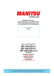
Manitou MT-X 1840
The pricing of the Manitou loader is comparable to that of other manufacturers’ versions. Many of the series’ machines are inexpensive and of great quality and dependability.
Manitou MLT 635
The manufacturer may be pleased with the new MLT 635 – 130 PS+, which features a revised cab and enhanced performance. This permits the effective handling of weights up to 3,5 tons and 6.08 meters in height.
The machine’s outstanding capabilities enable users to accomplish various tasks, including carrying animal feed, harvesting, and bulk loading and unloading. As a result, this equipment will appeal to dairy and livestock employees, cereal farmers, cooperatives, and agricultural contractors.
Every aspect has been meticulously crafted inside and out to meet the operator’s needs. For example, the PS models include a power-assisted transmission with additional gears and a high peak speed.
Manitou MLT 730-115V
This loader has been developed to efficiently manage loads weighing up to 3000 kg and measuring up to 6.95 meters in height. The cab is built for comfort, with simple entry, excellent visibility, and soundproofing, making it suitable for lengthy usage. It had a Deutz engine with 116 horsepower and a ground clearance of 39 centimeters.
The M-Variosift gearbox allows for adapting driving speeds up to 40 km/h and tractive effort to the driving conditions. The speed may be selected directly from the (+/-) buttons on the JSM. M-Variosift ensures precise control.
Manitou MLT 737-130 PS+
The loader is designed for productivity, efficiency, and comfort. It has a lifting height of 6.88 meters and a lifting capacity of 3.7 tons and is designed to treat agricultural commodities.
The cab’s design prioritizes comfort, accessibility, and visibility. The cab is appropriate for longer usage due to a JSM system (joystick and switch) set on a floating armrest, double switch buttons (DSB), and soundproofing.
The loader features a Deutz engine with 129 horsepower and a PowershiftPlus gearbox. Principal attributes:
- Limited slip differential;
- 41 cm ground clearance;
- The automated dust collection system for radiators is ideally suited for agricultural usage.
This model has an extensive selection of tires to improve performance in every working situation. In addition, new hydraulic features and a variable displacement piston pump with a flow rate of 150 l/min provide unmatched performance.
Manitou MLT 845-120H
With a maximum load capacity of 4,500 kilograms and a maximum speed of 33 kilometers per hour, the telehandler MLT 845-120 H is the ideal machine for tasks requiring a maximum load capacity of 4,500 kilograms and a maximum speed of 33 kilometers per hour.
Its remarkable features make it possible to complete all farm management tasks:
- Feeding animals;
- bulk loading and unloading;
- processing hay and straw, etc.
The MLT 845 is equipped with a Mercedes 4.2L, 121-horsepower, four-cylinder engine, which provides the necessary power and an optimal power-to-weight ratio. Therefore, this engine is suitable for any purpose. The hydrostatic transmission (MLT 845-120 H) has a two-speed manual transmission.
Manitou MLT 735
The performance of the Manitou 735 loader surpasses that of the MLT 634 and MLT 741 modules. The 735 model combines its predecessors’ characteristics with various innovative features. This includes a Tier 3 compliant engine and the new Evolution design.
Other benefits: better illumination, air conditioning, and joystick JSM.
As EPA rules require, the new Tier 3 engines use sophisticated technology such as CommonRail fuel injection systems and computer control to decrease particle emissions. Improved torque, quick throttle response, a quiet engine, enhanced fuel efficiency, and compatibility with B20 biodiesel are further advantages of sophisticated technology.
В настоящее время вы находитесь на странице с руководствами Manitou электропогрузчик. Выберите один из продуктов, чтобы сразу перейти к руководству по этому продукту. Не можете найти Manitou ? Тогда попробуйте вбить в поле поиска Manitou и модель, чтобы найти нужное руководство Manitou. На ManualsPDF.ru в настоящее время имеется 3 руководств Manitou . Самые популярные Manitou электропогрузчик:
- Manitou MT 1335 ST3B
- Manitou MT 1135 ST3B
- Manitou MT 835 ST3B
Последнее добавленное руководство Manitou было добавлено 2018-02-15, и это Manitou MT 1135 ST3B.
- Manuals
- Brands
- Manitou Manuals
- Front End Loaders
- A Series
- Manual
-
Contents
-
Table of Contents
-
Bookmarks
Quick Links
Related Manuals for Manitou A Series
Summary of Contents for Manitou A Series
-
Page 2
1st DATE OF ISSUE 05 / 01 / 2001 DATE OF ISSUE OBSERVATION 05 / 01 / 2001 ISSUE 09 / 03 / 2001 — UP DATING (2-5 to 2-8 ; 2-10 ; 2-12 ; 2-16 ; 2-20 ; 2-22 ; 2-24 ; 2-26 ; 2-30 ; 2-34 to 2-37 ;… -
Page 4: Table Of Contents
TABLE OF CONTENTS 1 — O 1 — 1 PERATING AND SAFETY INSTRUCTIONS – ORIGINAL REPLACEMENT PARTS AND ATTACHMENTS 1 — 3 – DRIVER’S OPERATING INSTRUCTIONS 1 — 4 • CAUTION 1 — 4 • GENERAL INSTRUCTIONS 1 — 6 •…
-
Page 6
O P E R A T I N G O P E R A T I N G A N D S A F E T Y A N D S A F E T Y I N S T R U C T I O N S I N S T R U C T I O N S 1 — 1… -
Page 7
1 — 2… -
Page 8: Original Replacement Parts And Attachments
— Only the manufacturer knows the details of the lift truck design and therefore has the best technological capability to carry out maintenance. ORIGINAL REPLACEMENT PARTS ARE DISTRIBUTED EXCLUSIVELY BY MANITOU AND ITS DEALER NETWORK. The dealer network list is available on MANITOU web site www.manitou.com…
-
Page 9: Driver’s Operating Instructions
DRIVER’S OPERATING INSTRUCTIONS AUTION WHENEVER YOU SEE THIS SYMBOL IT MEANS : WARNING ! BE CAREFUL ! YOUR SAFETY OR THE SAFETY OF THE LIFT TRUCK IS AT RISK. — Most accidents connected with the use, maintenance and repair of the lift truck are due to non application of the basic safety instructions.
-
Page 10
1 — 5… -
Page 11: General Instructions
ENERAL INSTRUCTIONS A — THE LIFT TRUCK’S SUITABILITY FOR THE JOB — The manufacturer has ensured that this lift truck is suitable for use under the standard operating conditions defined in this operator’s manual, with a static test coefficient of 1.33 and a dynamic test coefficient of 1, as specified in harmonised norm EN 1459 for variable range trucks.
-
Page 12
E — ENVIRONMENT — A lift truck operating in an area without fire extinguishing equipment must be equipped with an individual extinguisher. There are optional solutions, consult your dealer. — Take into account climatic and atmospheric conditions of the site of utilisation. . -
Page 13: Operating Instructions
PERATING INSTRUCTIONS A — DRIVER’S OPERATING INSTRUCTIONS — Wear clothes suited for driving the lift truck, avoid loose clothes. — Make sure you have the appropriate protective equipment for the job to be done. — Prolonged exposure to high sound levels may cause hearing problems. To protect your ears from uncomfortable sound levels, wear ear protectors.
-
Page 14
INSTRUCTIONS — Make sure that the forward/reverse lever is in neutral. — Turn the ignition key to the position I to activate the electrical system. — Check the level on the fuel level gauge. — Turn the ignition key to position II to preheat for 15 seconds. — Press the accelerator pedal and turn the ignition key fully : the I.C. -
Page 15
E — STOPPING THE LIFT TRUCK SAFETY NOTICE — Before stopping the lift truck after a long working period, leave the I.C. engine idling for a few moments, to allow the coolant liquid and oil to lower the temperature of the I.C. engine and transmission. Do not forget this precaution, in the event of frequent stops or warm stalling of the I.C. -
Page 16
INSTRUCTIONS — Ensure that the flashing light is in position and that it is working. — Check the good working order and cleanness of lights, indicators and windscreen wiper. — Switch off the working headlights if the lift truck is fitted with them. — Control the alignment of the wheels and select the steering mode HIGHWAY TRAFFIC. -
Page 17: Instructions For Moving The Lift Truck During Handling Operations
• or authorised exceptionally under certain conditions (see current regulations in the country where the lift truck is in use). — MANITOU supplies equipment specifically designed for lifting people. — Avoid travelling for a long distance in reverse. B — ATTACHMENTS — Ensure that the attachment is correctly fitted and locked to its frame.
-
Page 18
D — HANDLING — Always consider safety and only transport balanced and correctly secured loads to avoid any risk of tipping. — Fully engage forks under the load and move it in the transport position (The forks 300 mm from the ground, the jib retracted to the maximum and the carriage sloping backwards). -
Page 19: Instructions For Handling A Load
NSTRUCTIONS FOR HANDLING A LOAD A — WEIGHT OF LOAD AND CENTRE OF GRAVITY Carrying a load greater than the rated capacity for the lift truck or for the attachment 500 mm is prohibited. — Before taking up a load, you must know its weight and its centre of gravity. — The load chart relating to your lift truck is valid for a weight with its centre of gravity 500 mm from the heel of the forks (Fig.
-
Page 20
C — TAKING UP A HIGH LOAD ON TYRES Do not lift the jib under any circumstances if the lift truck is not laterally horizontal (See paragraph : G — LATERAL HORIZONTALITY OF THE LIFT TRUCK in the chapter : INSTRUCTIONS FOR HANDLING A LOAD). -
Page 21
D — LAYING A HIGH LOAD ON TYRES Do not lift the jib under any circumstances if the lift truck is not laterally horizontal (See paragraph : G — LATERAL HORIZONTALITY OF THE LIFT TRUCK in the chapter : INSTRUCTIONS FOR HANDLING A LOAD). — Approach the load in the transport position in front of the pile (Fig. -
Page 22
G — LATERAL HORIZONTALITY OF THE LIFT TRUCK — The lift truck’s lateral horizontality must be ascertained with the jib in low position. — Apart from the transverse slope of the ground, several parameters can upset the stability of the lift truck. •… -
Page 23: Maintenance Instructions Of The Lift Truck
MAINTENANCE INSTRUCTIONS OF THE LIFT TRUCK AINTENANCE INSTRUCTIONS A — GENERAL — Read the operator’s manual carefully and ensure you understand it. — Stop the I.C. engine and remove the ignition key, when an intervention is necessary. — Wear clothes suitable for the maintenance of the lift truck, avoid wearing jewellery and loose clothes. Tie and protect your hair, if necessary.
-
Page 24
D — WASHING — Clean the lift truck or at least the area concerned before any intervention. — Remember to close and lock all accesses to the lift truck (door, window, bonnet…). — During washing, avoid the articulations and electrical components and connections. If necessary, protect against penetration of water, steam or cleaning agents, components susceptible of being damaged, particularly electrical components and connections and the injection pump. -
Page 25: Before Starting Up A New Lift Truck
BEFORE STARTING UP A NEW LIFT TRUCK INTRODUCTION — Our lift trucks have been designed for easy handling by the operator and maximum ease of maintenance for the mechanic. — However, before commencing to operate the lift truck, the user should carefully read and understand the various chapters of this manual which has been provided to solve driving and maintenance problems.
-
Page 26
ELECTRICAL CIRCUIT — Check the level and the density of the electrolyte in the battery (See chapter : B — EVERY 50 HOURS SERVICE in paragraph : 3 — MAINTENANCE). — Check the components of the electrical system, the connections and fastening devices. IF NECESSARY, CONSULT YOUR DEALER. -
Page 27: If The Lift Truck Is Not To Be Used For A Long Time
The following recommendations are intended to prevent the lift truck from being damaged when it is withdrawn from service for an extended period. For these operations, we recommend the use of a MANITOU protective product, reference 603726. Instructions for using the product are given on the packaging.
-
Page 28
RINGING THE LIFT TRUCK BACK INTO SERVICE — Remove the waterproof adhesive tape from all the holes. — Refit the intake hose. — Refit and reconnect the battery. — Remove the protection from the steering cylinder rods. — Perform the daily service (See chapter : A — DAILY OR EVERY 10 HOURS SERVICE in paragraph : 3 — MAINTENANCE). — Put the handbrake on and remove the axle stands. -
Page 29
1 — 24… -
Page 30: Escription
2 — D E S C R I P T I O N 2 — D E S C R I P T I O N 2 — 1…
-
Page 31
2 — 2… -
Page 32
2 — 3… -
Page 33: Identification Of The Lift Truck
CHARACTERISTICS in paragraph : 2 — DESCRIPTION. Puissance ISO/TR14396 Effort de traction Pression des pneumatiques (Bar) Effort vertical max. (sur accrochage remorque) N°240130 I.C. . B) ENGINE — Engine Nr . C) RANSMISSION — Type — MANITOU reference — Serial Nr 2 — 4…
-
Page 34
. D) NGLE GEAR — Type — MANITOU reference — Serial Nr . E) RONT AXLE — Type — Serial Nr — MANITOU reference . F) EAR AXLE — Type — Serial Nr — MANITOU reference . G) — Type… -
Page 35: Mlt 730 Turbo Powershift Série A 2 — 8 And
. H) MLT 629/730 Série A + Turbo MLT 629/633/730 -120 LS Série A — MANITOU reference MLT 633/730 LS Turbo Série A — Date of manufacture MLT 633/730 -120 LS POWERSHIFT Série A MLT 730 Turbo POWERSHIFT Série A MT 732 Série A + Turbo…
-
Page 36
2 — 7… -
Page 37
CHARACTERISTICS NGINE — Type MLT 629/730 Série A PERKINS 1004.42 (AR 81026 or AR 81334) MLT 629/730 Turbo Série A PERKINS 1004.40T (AK 80920 or AK 81335) MLT 629/633/730 -120 LS Série A PERKINS 1004.40TW (AM 80922 or AM 81337) MLT 633/730 LS Turbo Série A PERKINS 1004.40T (AK 80920 or AK 81335) MLT 633/730 -120 LS POWERSHIFT Série A… -
Page 38
RANSMISSION MLT 633/730 -120 LS POWERSHIFT Série A MLT 730 Turbo POWERSHIFT Série A — Type TURNER POWERTRAIN SYSTEMS — Torque converter SACHS — Gear box . Gear shifting Electro-hydraulic . Number of forward speeds . Number of reverse speeds — Gear reverser Electro-hydraulic NGLE GEAR… -
Page 39
CHARACTERISTICS MLT 629 Série A RONT AND REAR TYRES DIMENSIONS PRESSURE TYRE LOAD PRESSURE ON THE CONTACT SURFACE AREA OF THE CONTACT SURFACE HARD GROUND LIGHT GROUND HARD GROUND LIGHT GROUND STANDARD 15,5/80-24 SGI TL 12PR 4 Bar Front unladen 1600 kg 7,6 kg/cm2 2,1 kg/cm2… -
Page 40
PECIFICATIONS — Level of sound pressure in the driver’s cab LpA 82,5 dB (According to standard prEN 12053 : 1995) — Level of sound power in the LwA environment 105 dB (According to directive 2000 / 14 CE guaranteed) — Travel speed of the lift truck (Except particular conditions) . -
Page 41
CHARACTERISTICS MLT 629 Turbo Série A RONT AND REAR TYRES DIMENSIONS PRESSURE TYRE LOAD PRESSURE ON THE CONTACT SURFACE AREA OF THE CONTACT SURFACE HARD GROUND LIGHT GROUND HARD GROUND LIGHT GROUND STANDARD 17,5LR24 XM27 TL 145A8 3,5 Bar Front unladen 1600 kg 1,6 kg/cm2 kg/cm2… -
Page 42
PECIFICATIONS — Level of sound pressure in the driver’s cab LpA 81 dB (According to standard prEN 12053 : 1995) — Level of sound power in the LwA environment 106 dB (According to directive 2000 / 14 CE guaranteed) — Travel speed of the lift truck (Except particular conditions) . -
Page 43
CHARACTERISTICS MLT 629 -120 LS Série A RONT AND REAR TYRES DIMENSIONS PRESSURE TYRE LOAD PRESSURE ON THE CONTACT SURFACE AREA OF THE CONTACT SURFACE HARD GROUND LIGHT GROUND HARD GROUND LIGHT GROUND STANDARD 17,5LR24 XM27 TL 145A8 3,5 Bar Front unladen 1600 kg 1,6 kg/cm2… -
Page 44
PECIFICATIONS — Level of sound pressure in the driver’s cab LpA 79,5 dB (According to standard prEN 12053 : 1995) — Level of sound power in the LwA environment 107 dB (According to directive 2000 / 14 CE guaranteed) — Travel speed of the lift truck (Except particular conditions) . -
Page 45
DIMENSIONS AND LOAD CHART MLT 629 Série A MLT 629 Turbo Série A MLT 629 -120 LS Série A MLT629 50° 60° 62.5° 40° 6,05 30° 20° 10° 0° -3.5° 0.5m 3,25 2,70 2,10 1,70 1,19 1,45 SUIVANT NORME EN 1459 annexe B. 2 — 16… -
Page 46
MLT 629 MLT 629 MLT 629 Série A Turbo Série A -120 LS Série A 1200 mm 1200 mm 1200 mm 2560 mm 2560 mm 2560 mm 1142 mm 1142 mm 1142 mm 1047 mm 1047 mm 1047 mm 4497 mm 4497 mm 4497 mm 4402 mm… -
Page 47
CHARACTERISTICS MLT 633 LS Turbo Série A MLT 633 -120 LS Série A MLT 633 -120 LS POWERSHIFT Série A RONT AND REAR TYRES DIMENSIONS PRESSURE TYRE LOAD PRESSURE ON THE CONTACT SURFACE AREA OF THE CONTACT SURFACE HARD GROUND LIGHT GROUND HARD GROUND LIGHT GROUND STANDARD 17,5LR24 XM27 TL 145A8 3,5 Bar… -
Page 48
YDRAULIC CIRCUIT — Type of pump Variable displacement piston pump . Capacity 60 cm3 — Lifting, tilting, telescoping, attachment circuit . Max. rating capacity unladen 144 L/min . Pressure 270 Bar — Steering circuit . Max. rating capacity unladen 144 L/min . -
Page 49
— Telescoping motions (Lifting jib) . Unladen extending 5,2 s 24,2 m/mn . Laden extending 6,2 s 20,3 m/mn . Unladen retracting 4,2 s 30 m/mn . Laden retracting 4,1 s 30,7 m/mn — Reverse tilt time unladen 2,9 s 49,5 °/s — Forward tilt time unladen 2,7 s… -
Page 50
2 — 21… -
Page 51
DIMENSIONS AND LOAD CHART MLT 633 LS Turbo Série A MLT 633 -120 LS Série A MLT 633 -120 LS POWERSHIFT Série A MLT 633 50° 60° 63.5° 6,05 40° 30° 20° 10° 0° -3.5° 0.5m 3,25 2,55 1,80 1,19 2,05 1,55 SUIVANT NORME EN 1459 annexe B. -
Page 52
MLT 633 MLT 633 MLT 633 -120 LS LS Turbo Série A -120 LS Série A POWERSHIFT Série A 1200 mm 1200 mm 1200 mm 2560 mm 2560 mm 2560 mm 1142 mm 1142 mm 1142 mm 1047 mm 1047 mm 1047 mm 4462 mm 4462 mm… -
Page 53
CHARACTERISTICS MLT 730 Série A RONT AND REAR TYRES DIMENSIONS PRESSURE TYRE LOAD PRESSURE ON THE CONTACT SURFACE AREA OF THE CONTACT SURFACE HARD GROUND LIGHT GROUND HARD GROUND LIGHT GROUND STANDARD 15,5/80-24 SGI TL 12PR 4 Bar Front unladen 1650 kg 7,9 kg/cm2 2,1 kg/cm2… -
Page 54
PECIFICATIONS — Level of sound pressure in the driver’s cab LpA 82,5 dB (According to standard prEN 12053 : 1995) — Level of sound power in the LwA environment 105 dB (According to directive 2000 / 14 CE guaranteed) — Travel speed of the lift truck (Except particular conditions) . -
Page 55
CHARACTERISTICS MLT 730 Turbo Série A RONT AND REAR TYRES DIMENSIONS PRESSURE TYRE LOAD PRESSURE ON THE CONTACT SURFACE AREA OF THE CONTACT SURFACE HARD GROUND LIGHT GROUND HARD GROUND LIGHT GROUND STANDARD 17,5LR24 XM27 TL 145A8 3,5 Bar Front unladen 1650 kg 1,6 kg/cm2 kg/cm2… -
Page 56
PECIFICATIONS — Level of sound pressure in the driver’s cab LpA 81 dB (According to standard prEN 12053 : 1995) — Level of sound power in the LwA environment 106 dB (According to directive 2000 / 14 CE guaranteed) — Travel speed of the lift truck (Except particular conditions) . -
Page 57
CHARACTERISTICS MLT 730 Turbo POWERSHIFT Série A RONT AND REAR TYRES DIMENSIONS PRESSURE TYRE LOAD PRESSURE ON THE CONTACT SURFACE AREA OF THE CONTACT SURFACE HARD GROUND LIGHT GROUND HARD GROUND LIGHT GROUND STANDARD 17,5LR24 XM27 TL 145A8 3,5 Bar Front unladen 1650 kg 1,6 kg/cm2… -
Page 58
PECIFICATIONS — Level of sound pressure in the driver’s cab LpA 81 dB (According to standard prEN 12053 : 1995) — Level of sound power in the LwA environment 106 dB (According to directive 2000 / 14 CE guaranteed) — Travel speed of the lift truck (Except particular conditions) . -
Page 59
CHARACTERISTICS MLT 730 LS Turbo Série A MLT 730 -120 LS Série A MLT 730 -120 LS POWERSHIFT Série A RONT AND REAR TYRES DIMENSIONS PRESSURE TYRE LOAD PRESSURE ON THE CONTACT SURFACE AREA OF THE CONTACT SURFACE HARD GROUND LIGHT GROUND HARD GROUND LIGHT GROUND STANDARD 17,5LR24 XM27 TL 145A8 3,5 Bar… -
Page 60
PECIFICATIONS — Level of sound pressure in the driver’s cab LpA (According to standard prEN 12053 : 1995) MLT 730 LS Turbo Série A 81 dB MLT 730 -120 LS Série A 79,5 dB MLT 730 -120 LS POWERSHIFT Série A 79,5 dB — Level of sound power in the LwA environment (According to directive 2000 / 14 CE guaranteed) -
Page 61
— Axle weight with attached equipment (Transport position) . Front unladen 3330 kg Rated load 8640 kg . Rear unladen 3810 kg Rated load 1500 kg — Tensible strain at coupling hook . Unladen MLT 730 LS Turbo Série A 5600 daN MLT 730 -120 LS Série A 5500 daN… -
Page 62
2 — 33… -
Page 63
DIMENSIONS AND LOAD CHART MLT 730 Série A MLT 730 LS Turbo Série A MLT 730 Turbo Série A MLT 730 -120 LS Série A MLT 730 Turbo POWERSHIFT Série A MLT 730 -120 LS POWERSHIFT Série A MLT730 50° 60°… -
Page 64
MLT 730 MLT 730 MLT 730 MLT 730 Turbo MLT 730 MLT 730 -120 LS Série A Turbo Série A LS Turbo Série A POWERSHIFT Série A -120 LS Série A POWERSHIFT Série A 1200 mm 1200 mm 1200 mm 1200 mm 1200 mm 1200 mm… -
Page 65
CHARACTERISTICS MT 732 Série A MT 732 Turbo Série A RONT AND REAR TYRES DIMENSIONS PRESSURE TYRE LOAD PRESSURE ON THE CONTACT SURFACE AREA OF THE CONTACT SURFACE HARD GROUND LIGHT GROUND HARD GROUND LIGHT GROUND STANDARD 14,9×24 T35 Stabilarge 18PR 3,4 Bar Front unladen 1550 kg… -
Page 66
PECIFICATIONS — Level of sound pressure in the driver’s cab LpA (According to standard prEN 12053 : 1995) MT 732 Série A 82,5 dB MT 732 Turbo Série A 81 dB — Level of sound power in the LwA environment (According to directive 2000 / 14 CE guaranteed) MT 732 Série A 105 dB… -
Page 67
DIMENSIONS AND LOAD CHART MT 732 Série A MT 732 Turbo Série A MT732 50° 60° 63° 40° 6,90 30° 20° 10° 0° -3° 0.5m 4,16 3,60 2,90 2,10 1,45 2,40 1,75 SUIVANT NORME EN 1459 annexe B. 2 — 38… -
Page 68
MT 732 MT 732 Série A Turbo Série A 1200 mm 1200 mm 2560 mm 2560 mm 1393 mm 1393 mm 1297 mm 1297 mm 4713 mm 4713 mm 4617 mm 4617 mm 3905 mm 3905 mm 5913 mm 5913 mm 1846 mm 1846 mm 1846 mm… -
Page 69: Mt 932 Série A
CHARACTERISTICS MT 932 Série A RONT AND REAR TYRES DIMENSIONS PRESSURE TYRE LOAD PRESSURE ON THE CONTACT SURFACE AREA OF THE CONTACT SURFACE HARD GROUND LIGHT GROUND HARD GROUND LIGHT GROUND STANDARD 14,9×24 T35 Stabilarge 18PR 3,4 Bar Front unladen 1650 kg 5,7 kg/cm2 2 kg/cm2…
-
Page 70
PECIFICATIONS — Level of sound pressure in the driver’s cab LpA 82,5 dB (According to standard prEN 12053 : 1995) — Level of sound power in the LwA environment 105 dB (According to directive 2000 / 14 CE guaranteed) — Travel speed of the lift truck (Except particular conditions) . -
Page 71
DIMENSIONS AND LOAD CHART MT 932 Série A MT932 50° 60° 61.5° 40° 30° 20° 10° 0° -5° 0.5m 6,10 4,75 3,60 2,40 1,44 6,58 5,40 4,20 2,95 1,90 SUIVANT NORME EN 1459 annexe B. 2 — 42… -
Page 72
MT 932 Série A 1200 mm 2560 mm 1393 mm 1297 mm 4713 mm 4617 mm 3905 mm 5913 mm 1846 mm 1846 mm 460 mm 440 mm 445 mm 760 mm 865 mm 1040 mm 45 mm 1690 mm 125 mm 47,5 °… -
Page 73: Instruments And Controls
INSTRUMENTS AND CONTROLS 2 — 44…
-
Page 74
ESCRIPTION 1 — DRIVER’S SEAT 2 — SAFETY BELT 3 — CONTROL AND SIGNAL LIGHTS PANEL 4 — LOAD STATUS INDICATOR 5 — SWITCH PANEL 6 — SWITCH AND LAMPS FOR ALIGNMENT OF THE WHEELS 7 — LIGHT SWITCH, HORN AND INDICATOR SWITCH 8 — IGNITION SWITCH 9 — BRAKING OIL TANK AND WINDSCREEN WASHER ACCESS PANEL 10 — BRAKING OIL TANK… -
Page 75
1 — D RIVER S SEAT OPTION MLT 629/730 Série A MLT 629/730 Turbo Série A MLT 629/633/730 -120 LS Série A MLT 633/730 LS Turbo Série A MLT 633/730 -120 LS POWERSHIFT Série A MLT 730 Turbo POWERSHIFT Série A STANDARD MT 732/932 Série A MT 732 Turbo Série A… -
Page 76
SEAT DEPTH ADJUSTMENT (FIG. D) The depth of the seat may be adjusted to suit the individual. — Press the right-hand button while raising or lowering the seat to find the desired position. EXTENDING THE HEAD-REST (FIG. E) — The height of the back-rest can be adjusted by pulling it upwards (The notches will click) up to the stop. -
Page 77
1 — P NEUMATIC DRIVER S SEAT PTION DESIGNED FOR MAXIMUM COMFORT, THIS SEAT CAN BE ADJUSTED AS FOLLOWS. WEIGHT AND SEAT HEIGHT ADJUSTMENT WEIGHT ADJUSTMENT (FIG. A) It is advised that you adjust the seat according to your weight when sitting. — Switch on lift truck ignition. -
Page 78
ADJUSTMENT OF THE ANGLE OF THE BACK-REST (FIG. G) — Support the back-rest, pull the lever and position the back-rest to find the desired position. If you do not support the back-rest when making adjustments, it swings completely forwards. HORIZONTAL SHOCK ABSORBER (FIG. H) In certain conditions (e.g. -
Page 79
3 — C ONTROL AND SIGNAL LIGHTS PANEL CONTROL INSTRUMENTS MLT . . . Série A B1 B2 B3 B4 A — HOURMETER AND REV COUNTER MLT 629/730 Série A MLT 629/730 Turbo Série A MLT 629/633/730 -120 LS Série A MLT 633/730 LS Turbo Série A MLT 633/730 -120 LS POWERSHIFT Série A MLT 730 Turbo POWERSHIFT Série A… -
Page 80
F — RED BRAKING OIL LEVEL LAMP If the lamp and the buzzer come on, when the lift truck is running, stop the I.C. engine immediately and check the braking oil level. In the event of an abnormal dropping of the level, consult your dealer. G — RED PARKING BRAKE LAMP This lamp comes on when the parking brake is applied. -
Page 81
C — TEST SWITCH (FIG. A) Press the switch to check at any time the correct functioning of the load status indicator. — Correct operation : All leds and the sound alarm function continuously. — Faulty operation : All leds and the sound alarm function intermittently (Stop the lift truck and consult your dealer, never attempt a repair yourself). -
Page 82
F — TRANSMISSION CUT-OFF The switch selects transmission cut-off to the service brake pedal or the hydraulic controls lever (See chapter : 37 — USE OF TRANSMISSION CUT-OFF in paragraph : 2 — DESCRIPTION). Position A : Indicator light on, transmission cut-off to service brake pedal effected. -
Page 83
6 — S WITCH AND LAMPS FOR ALIGNMENT OF THE WHEELS Before selecting one of the three possible steering positions, bring the 4 wheels into alignment, i.e., in the straight ahead position. A — GREEN LAMPS FOR ALIGNMENT OF THE WHEELS These lamps come on to indicate the alignment of the wheels, in relation to the axle of the lift truck. -
Page 84
10 — B RAKING OIL TANK See chapter : B — EVERY 50 HOURS SERVICE in paragraph : 3 — MAINTENANCE. 11 — W INDSCREEN WASHER TANK See chapter : B — EVERY 50 HOURS SERVICE in paragraph : 3 — MAINTENANCE. 12 — F USE AND RELAY ACCESS PANEL — Lift up the fuse and relay access panel 1. -
Page 85
F8 — (15A MAX.) — Gear reverser (15A). — Transmission cut-off (15A). — Reverse lights (15A). — Reverse buzzer alarm (15A). (g-h) — OPTION Reverse buzzer alarm (15A). (a-b-c-d-e-f) F9 — (10A MAX.) — Control instruments panel (5A). F10 — (15A MAX.) — Sound alarm (15A). — Stop switch (15A). -
Page 86
14 — R OOF LIGHT 15 — A CCELERATOR PEDAL 16 — S ERVICE BRAKE PEDAL AND TRANSMISSION CUT The pedal applies on the front and rear wheels by an hydraulic brake system, and allows the lift truck to be slowed down and stopped. -
Page 87
18 — F ORWARD REVERSE LEVER MLT 629/730 Série A MLT 629/730 Turbo Série A MLT 629/633/730 -120 LS Série A MLT 633/730 LS Turbo Série A MT 732/932 Série A MT 732 Turbo Série A When operating this control, the lift truck should be travelling at slow speed and not accelerating. -
Page 88
The choice of gear ratio should be made carefully according to the nature of the work being carried out. A poor choice may result in the extremely rapid elevation of the transmission oil temperature through excessive slipping of the converter, which could lead to serious damage to the transmission (it is essential to stop and change the working conditions if the transmission oil temperature indicator light comes on). -
Page 89
20 — S TEERING SELECTION LEVER CRAB HIGHWAY 4 WHEEL STEER TRAFFIC STEER Before selecting one of the three possible steering positions, bring the 4 wheels into alignment, i.e., in the straight ahead position. (See chapter : 6 — SWITCH AND LAMPS FOR ALIGNMENT OF THE WHEELS in paragraph : 2 — DESCRIPTION). -
Page 90
22 — L OAD CHARTS FILE This file includes the description of the hydraulic controls and the load charts of the attachments used on the lift truck. 23 — H EATER CONTROL A — HEATING FAN CONTROL This 3-speed control regulates warm or cold air through the heating ventilators. B — HEATING TEMPERATURE CONTROL Allows the temperature inside the cab to be adjusted. -
Page 91
CONDITIONED AIR MODE The controls must be adjusted in the following way : A — Control with signal light on. B — At the end of travel to the left. C — At the required temperature. D — At the required temperature 1, 2 or 3. DEMISTING MODE The controls must be adjusted in the following way : A — Control with signal light on. -
Page 92
32 — F RONT LIGHTS A — Left front indicator. B — Left front dipped headlight. C — Left front main beam. D — Left front sidelight. E — Right front indicator. F — Right front dipped headlight. G — Right front main beam. H — Right front sidelight. -
Page 93
36 — S TEERING WHEEL REGULATING HANDLE MLT 629/730 Série A MLT 629/730 Turbo Série A MLT 629/633/730 -120 LS Série A MLT 633/730 LS Turbo Série A MLT 633/730 -120 LS POWERSHIFT Série A MLT 730 Turbo POWERSHIFT Série A This handle enables the angle and height of the steering wheel to be adjusted. -
Page 94
2 — 65… -
Page 95: Towing Pin And Hook
TOWING PIN AND HOOK Located at the rear of the lift truck, this device is used to attach a trailer. Its capacity is limited for each lift truck by the Authorised Gross Vehicle Weight (A.G.V.W), tractive effort and maximum vertical force on the coupling point. This information is given on the manufacturer’s plate fixed to each lift truck (See chapter : IDENTIFICATION OF THE LIFT TRUCK in paragraph : 2 — DESCRIPTION).
-
Page 96
C — C ) (F . C) OUPLING LADDER PTION COUPLING AND UNCOUPLING THE TRAILER — To couple the trailer, position the lift truck as close as possible to the trailer ring. — Put the handbrake on and switch off the engine. ON THE FIXED PIN — Remove pin 1, remove rod 2 and raise latch 3. -
Page 97
G — H ) (F . G — H — I) YDRAULIC TRAILER HOOK PTION MLT 629/633/730 -120 LS Série A MLT 633/730 LS Turbo Série A MLT 633/730 -120 LS POWERSHIFT Série A NOTE : The rear-view mirror OPTION is mandatory with the hydraulic trailer tow hook. — Raise the hydraulic tow hook to release the hook lock 1 (Fig. -
Page 98
2 — 69… -
Page 99: Description And Use Of Electric And Hydraulic Options
DESCRIPTION AND USE OF ELECTRIC AND HYDRAULIC OPTIONS 1 — R EAR ELECTRIC SOCKET Enables power supply connection for a trailer (See chapter : TOWING PIN AND HOOK in paragraph : 2 — DESCRIPTION) or signalling bar. Left rear indicator Rear stoplight Left tail light Right tail light…
-
Page 100
7 — P REHEATING ROD Enables the motor unit to be kept warm during prolonged periods of stoppage and thus, ensures the improved start-up of the I.C. engine. SUPPLY CHARACTERISTICS OF PREHEATING SYSTEM : • Rated range of power : 220-240V ; 50-60Hz •… -
Page 101
10 — E XTERIOR DRAIN BACK Enables connection of an attachment for which drain-back is required. 11 — H YDRAULIC ATTACHMENT LOCKING Enables attachment locking to be controlled on the carriage and the use of a hydraulic attachment on the same hydraulic circuit (See chapter : PICKING UP THE ATTACHMENTS in paragraph : 4 — ADAPTABLE ATTACHMENTS IN OPTION ON THE RANGE). -
Page 102
FUNCTIONING MLT 629/730 Turbo Série A MLT 629/633/730 -120 LS Série A MLT 633/730 LS Turbo Série A MLT 633/730 -120 LS POWERSHIFT Série A MLT 730 Turbo POWERSHIFT Série A — Button 3 not engaged, buttons 4 and 5 control a hydraulic function. — Pressing button 3, buttons 4 and 5 control another hydraulic function. -
Page 103
15 — C » S » » A » O U T I M P L E G G R AVAT I N G H Y D R A U L I C MOVEMENTS Switch 1 enables or disables the «SIMPLE» or «AGGRAVATING» hydraulic movement cut out device. -
Page 104
17 — S I N G L E O R D U A L E F F E C T R E A R H Y D R A U L I C C O N T R O L PREDISPOSITION Enables the use of a hydraulic accessory at the rear of the lift truck (e.g. -
Page 105
19 — D UAL EFFECT REAR HYDRAULIC CONTROL PREDISPOSITION S I N G L E O R D U A L E F F E C T R E A R H Y D R A U L I C C O N T R O L PREDISPOSITION Switch 1 controls one or the other of the rear hydraulic predispositions. -
Page 106: Aintenance
3 — M A I N T E N A N C E 3 — M A I N T E N A N C E 3 — 1…
-
Page 107
3 — 2… -
Page 108: Filters Cartridges And Belts
FILTERS CARTRIDGES AND BELTS MLT 629/730 Série A MT 732/932 Série A MT 732 Turbo Série A DESIGNATION PART NUMBER CLEAN CHANGE 1 — Engine oil filter MLT 629/730 Série A 133755 500 H MT 732/932 Série A 133755 500 H MT 732 Turbo Série A 476954 500 H…
-
Page 109
MLT 629/730 Turbo Série A MLT 730 Turbo POWERSHIFT Série A DESIGNATION PART NUMBER CLEAN CHANGE 1 — Engine oil filter 476954 500 H 2 — Dry air filter cartridge 563416 50 H * 500 H * 3 — Safety dry air filter cartridge 563415 1000 H * 4 — Transmission oil filter… -
Page 110
MLT 629/633/730 -120 LS Série A MLT 633/730 LS Turbo Série A MLT 633/730 -120 LS POWERSHIFT Série A DESIGNATION PART NUMBER CLEAN CHANGE 1 — Engine oil filter 476954 500 H 2 — Dry air filter cartridge 563416 50 H * 500 H * 3 — Safety dry air filter cartridge 563415… -
Page 111: Lubricants And Fuel
LUBRICANTS AND FUEL I.C. ENGINE ORGANS TO BE LUBRICATED CAPACITY RECOMMENDATION PACKAGING PART NUMBER I.C. ENGINE MANITOU Oil 20 L. 582357 MLT 629/730 Série A 7,75 Liters API CG4 55 L. 582358 MLT 629/730 Turbo Série A 7,75 Liters 209 L.
-
Page 112
USE THE RECOMMENDED LUBRICANTS : — For topping up, oils do not necessarily have to be miscible. — For oil changes, MANITOU oils are perfectly suitable. DIAGNOSTIC ANALYSIS OF OIL In the event of a maintenance or service contract with the dealer you may be requested to provide a sample of a selected component’s oil, for diagnostic analysis. -
Page 113: Servicing Schedule
SERVICING SCHEDULE A = AJUST N = CLEAN After 1 year 1 year C = CHECK P = BLEED 2000 4000 first 50 hours hours 1000 hours hours D = DESCALE R = CHANGE hours hours hours hours G = GREASE V = DRAIN I.C.
-
Page 114
A = AJUST N = CLEAN After 1 year 1 year C = CHECK P = BLEED 2000 4000 first 50 hours hours 1000 hours hours D = DESCALE R = CHANGE hours hours hours hours G = GREASE V = DRAIN BRAKE Brake oil level . -
Page 115: A — Daily Or Every 10 Hours Service
A — DAILY OR EVERY 10 HOURS SERVICE A1 — I.C. ENGINE OIL LEVEL CHECK Place the lift truck on level ground with the I.C. engine stopped, and let the oil drain into the sump. — Open the I.C. engine bonnet. — Remove the dipstick 1 (Fig.
-
Page 116
A4 — C YCLONIC PREFILTER CLEAN The cleaning interval is given as a guide, however the prefilter must be emptied as soon as impurities reach the MAXI level on the tank. — Loosen nut 1 (Fig. A4), remove cover 2 (Fig. A4) and empty the tank. — Clean the prefilter unit with a clean dry cloth and reassemble the unit. -
Page 117
— Remove the surplus of grease. If the lift truck is used in an abrasive environment (Dust, sand, coal…) Use lubricating varnish (MANITOU Reference : 483 536). In this respect, consult your dealer. NOTE : MT 732/932 Série A MT 732 Turbo Série A MLT 730 . -
Page 118
3 — 13… -
Page 119: B — Every 50 Hours Service
The cartridge must not be blown anywhere near the air filter box. Never clean the cartridge by tapping it against a hard surface. Your eyes must be protected during this intervention. — Clean the cartridge seal surfaces with a damp, clean lint-free cloth and grease with a silicone lubricant (MANITOU Reference : 479 292).
-
Page 120
B4 — C ONDENSER CORE PTION AIR CONDITIONING B4/1 CLEAN — Open the engine bonnet. — Loosen the knurled screw 1 (Fig. B4/1) and swing round the filter and condenser unit. — Clean the core.with a blast of compressed air aimed from the inside towards the outside (Fig. -
Page 121
B5/2 B5/2 B5/3 MLT 629/633/730 ..MT 732/932 ..MLT 629/633/730 ..B5/3 B5/4 B5/4 MT 732/932 ..MLT 629/633 ..MLT 730 . -
Page 122
B6 — H YDRAULIC OIL LEVEL B6/1 CHECK Place the lift truck on level ground with the I.C. engine stopped, and the jib retracted and lowered as far as possible. — Refer to gauge 1 (Fig. B6/1). — The oil level is correct when it is at the level of the red point. — If necessary, add oil (See chapter : LUBRICANTS AND FUEL in paragraph : 3 — MAINTENANCE). -
Page 123
B8 — W INDSCREEN WASHER LIQUID LEVEL B8/1 CHECK — Loosen screw 1 (Fig. B8/1) and remove the access panel for braking oil tank and windscreen washer tank 2 (Fig. B8/1). — Check visually the level. — If necessary add windscreen washer liquid (See chapter : LUBRICANTS AND FUEL in paragraph : 3 — MAINTENANCE) by filler port 3 (Fig. -
Page 124
B11 — B ATTERY ELECTROLYTE LEVEL B11/1 CHECK Check the electrolyte level in each cell of the battery. If the lift truck is working in a high temperature environment, check the level more frequently than every 50 hours service. — Open the I.C. engine bonnet. — Open battery cowl 1 (Fig. -
Page 125
B14 — T RANSMISSION UNIVERSAL JOINT B14/1 GREASE Clean and lubricate the following points with grease (See chapter : LUBRICANTS AND FUEL in paragraph : 3 — MAINTENANCE) and remove the surplus of grease. 1 — Lubricators of the universal joint I.C. engine / Angle gear box (2 lubricators) (Fig. -
Page 126
3 — 21… -
Page 127: C — Every 250 Hours Service
C — EVERY 250 HOURS SERVICE Carry out the operations described previously as well as the following operations. C1 — F AN BELT TENSION C1/1 CHECK — ADJUST — Open the I.C. engine bonnet. — Check the belt for signs of wear and cracks and change if necessary (See chapter : FILTERS CARTRIDGES AND BELTS in paragraph : 3 — MAINTENANCE).
-
Page 128
C3 — C OMPRESSOR BELT TENSION PTION AIR CONDITIONING C3/1 CHECK — ADJUST — Open the engine bonnet. — Unscrew the fastening screws 1 (Fig. C3/1). — Lay down the protective guard 2 (Fig. C3/1). — Check the belt for signs of wear and cracks and change if necessary (See chapter : FILTERS CARTRIDGES AND BELTS in paragraph : 3 — MAINTENANCE). -
Page 129
C6 — C AB VENTILATION FILTER PTION AIR CONDITIONING CHANGE — Lift up protective casing 1 (Fig. C6). — Lift out cabin ventilation filter 2 (Fig. C6) and fit new replacement filter (See chapter : FILTERS CARTRIDGES AND BELTS in paragraph : 3 — MAINTENANCE). — Refit the protective casing. -
Page 130
3 — 25… -
Page 131: D — Every 500 Hours Service
D — EVERY 500 HOURS SERVICE Carry out the operations described previously as well as the following operations. D1 — I.C. ENGINE OIL D1/1 DRAIN D2 — I.C. ENGINE OIL FILTER CHANGE Place the lift truck on level ground, let the I.C. engine run at idle for a few minutes, then stop the I.C.
-
Page 132
D3 — D RY AIR FILTER CARTRIDGE D3/1 CHANGE In case of use in a heavily dust laden atmosphere, there are pre-filtration cartridges, see chapter : FILTERS CARTRIDGES AND BELTS in paragraph : 3 — MAINTENANCE. Also, the checking and cleaning periodicity of the cartridge must be reduced (up to 250 hours in a heavily laden dust atmosphere and with pre-filtration). -
Page 133
D5 — F UEL FEED PUMP D5/1 CLEAN — Open the bonnet. — Loosen connection 1 (Fig. D5/1), lift hose 2 (Fig. D5/1) and protect the aperture. — Remove connection 3 (Fig. D5/2) and lift strainer (Fig. D5/2). — Carefully clean the strainer and connection using a brush soaked in clean diesel fuel and dry them with a low pressure jet of compressed air. -
Page 134
D7 — H YDRAULIC RETURN OIL FILTER CARTRIDGE CHANGE Stop the I.C. engine and remove the pressure from the circuits by acting on the hydraulic controls. Thoroughly clean the outside of the filter and its surroundings before any intervention in order to prevent any risk of polluting the hydraulic circuit. — Place a container under hydraulic drain filter 1 (Fig. -
Page 135
D9 — P ARKING BRAKE MECHANISM GREASE — Clean and grease articulation axles 1 (Fig. D9) with grease (See chapter : LUBRICANTS AND FUEL in paragraph : 3 — MAINTENANCE). D10 — C AB VENTILATION FILTER CLEAN — Lift up protective casing 1 (Fig. D10). — Lift out cabin ventilation filter 2 (Fig. -
Page 136
D12 — F RONT AND REAR AXLE DIFFERENTIAL OIL DRAIN Place the lift truck on level ground with the engine stopped and the differential oil still warm. Dispose the drain oil in an ecological manner. — Place a container under drain plugs 1 (Fig. D12) and unscrew the plugs. — Remove level plug 2 (Fig. -
Page 137: E — Every 1000 Hours Service
E — EVERY 1000 HOURS SERVICE Carry out the operations described previously as well as the following operations. E1 — F UEL TANK E1/1 CLEAN While carrying out these operations, do not smoke or work near a flame. Place the lift truck on level ground with the I.C. engine stopped. — Inspect the parts susceptible to leaks in the fuel circuit and in the tank.
-
Page 138
E3 — T RANSMISSION OIL E3/1 DRAIN E4 — T RANSMISSION HOUSING STRAINER CLEAN MLT 629/730 Série A MLT 629/730 Turbo Série A MLT 629/633/730 -120 LS Série A MLT 633/730 LS Turbo Série A MT 732/932 Série A MT 732 Turbo Série A Place the lift truck on level ground with the I.C. -
Page 139
MLT 633/730 -120 LS POWERSHIFT Série A E3/5 MLT 730 Turbo POWERSHIFT Série A Place the lift truck on level ground with the I.C. engine stopped, the transmission oil still warm. DRAINING THE OIL — Place a container under drain plug 1 (Fig. E3/5) and under cover 2 (Fig. E3/6) and unscrew the drain plug. -
Page 140
E5 — A NGLE GEAR BOX OIL E5/1 DRAIN Place the lift truck on level ground with the I.C. engine stopped, the angle gear box oil still warm. — Place a container under drain plug 1 (Fig. E5/1) and unscrew the plug. — Remove dipstick 2 (Fig. -
Page 141
FILLING UP THE OIL E6/3 — Clean and refit drain plug 1 (Fig. E6/1) (Tightening torque 29 to 39 N.m). — Fill up with oil (See chapter : LUBRICANTS AND FUEL in paragraph : 3 — MAINTENANCE) by filler port 4 (Fig. E6/2). Use a clean container and funnel and clean the underside of the oil drum before filling. -
Page 142
E10 — F RONT AND REAR WHEELS REDUCERS OIL DRAIN Place the lift truck on level ground with the I.C. engine stopped and the reducers oil still warm. Dispose the drain oil in an ecological manner. — Drain and change each front wheel reducer. — Place drain plug 1 (Fig. -
Page 143: F — Every 2000 Hours Service
F — EVERY 2000 HOURS SERVICE Carry out the operations described previously as well as the following operations. F1 — C OOLING LIQUID F1/1 DRAIN These operations are to be carried out if necessary or every two years at the beginning of winter.
-
Page 144
F1/5 F1/6 3 — 39… -
Page 145: G — Occasional Maintenance
G — OCCASIONAL MAINTENANCE G1 — F UEL SYSTEM G1/1 BLEED These operations are to be carried out only in the following cases : — A component of the fuel system replaced or drained. — A drained tank. — Running out of fuel. Ensure that the level of fuel in the tank is sufficient, turn the ignition key to notch 1 to establish electrical contact and bleed in the following order : — Open the I.C.
-
Page 146
— Lift the wheel until it comes off the ground and put in place the safety support under the axle (Fig. G2/2). G2/2 For this operation, we advise you to use the hydraulic jack MANITOU Reference 505 507 and the safety support MANITOU Reference 554 772. — Completely unscrew the wheel nuts and remove them. -
Page 147
G3 — L IFT TRUCK Do not tow the lift truck at more than 25 km/h. — Put the forward/reverse lever and the gear shift in neutral (As model of lift truck). — Release the parking brake. — Put the warning lights on. — If the I.C. -
Page 148
G5 — L IFT TRUCK ON A PLATFORM G5/1 TRANSPORT Ensure that the safety instructions connected to the platform are respected before the loading of the lift truck and that the driver of the means of transport is informed about the dimensions and the weight of the lift truck (See chapter : CHARACTERISTICS in paragraph : 2 — DESCRIPTION). -
Page 149
G6 — F RONT HEADLAMPS ADJUST RECOMMENDED SETTING (As per standard ECE-76/756 76/761 ECE20) Set to — 2% of the dipped beam in relation to the horizontal line of the headlamp. ADJUSTING PROCEDURE — Place the lift truck unloaded and in the transport position and perpendicular to a white wall on flat, level ground (Fig. -
Page 150
3 — 45… -
Page 151: H — Every Two Years (Option Air Conditioning)
H — EVERY TWO YEARS (OPTION AIR CONDITIONING) WARNING : NEVER TRY TO REPAIR ANY ANOMALIES YOURSELF. TO RECHARGE A CIRCUIT, ALWAYS CONTACT YOUR DEALER WHO HAS THE APPROPRIATE SPARE PARTS, TECHNICAL TRAINING AND NECESSARY TOOLS. — Do not open the circuit under any circumstances as this would cause the coolant to be lost. — The cooling circuit contains a gas which can be dangerous under certain conditions.
-
Page 152
A D A P T A B L E A D A P T A B L E A T T A C H M E N T S A T T A C H M E N T S I N O P T I O N O N I N O P T I O N O N T H E R A N G E… -
Page 153
4 — 2… -
Page 154: Introduction
INTRODUCTION — A wide range of attachments studied and perfectly adapted to your lift truck is available and guaranteed by the manufacturer. — The attachments are delivered with a load chart concerning your lift truck. The operator’s manual and the load chart should be kept in the places provided in the lift truck.
-
Page 155: Picking Up The Attachments
PICKING UP THE ATTACHMENTS A — A TTACHMENT WITHOUT HYDRAULICS AND HAND LOCKING DEVICE B — A TTACHMENT WITHOUT HYDRAULICS AND HYDRAULIC LOCKING DEVICE PTION MLT 629/730 Série A MT 732/932 Série A MT 732 Turbo Série A C — A TTACHMENT WITHOUT HYDRAULICS AND HYDRAULIC LOCKING DEVICE PTION MLT 629/730 Turbo Série A…
-
Page 156
4 — 5… -
Page 157
A — A TTACHMENT WITHOUT HYDRAULICS AND HAND LOCKING DEVICE TAKING UP AN ATTACHMENT — Ensure that the attachment is in a position facilitating the locking to the carriage. If it is not correctly oriented, take the necessary precautions in order to move it safely. — Check that the locking pin and the clip are in position in the bracket (Fig. -
Page 158
B — A TTACHMENT WITHOUT HYDRAULICS AND HYDRAULIC LOCKING DEVICE PTION MLT 629/730 Série A MT 732/932 Série A MT 732 Turbo Série A TAKING UP AN ATTACHMENT — Ensure that the attachment is in a position facilitating the locking to the carriage. If it is not correctly oriented, take the necessary precautions in order to move it safely. -
Page 159
C — A TTACHMENT WITHOUT HYDRAULICS AND HYDRAULIC LOCKING DEVICE PTION MLT 629/730 Turbo Série A MLT 629/633/730 -120 LS Série A MLT 633/730 LS Turbo Série A MLT 633/730 -120 LS POWERSHIFT Série A MLT 730 Turbo POWERSHIFT Série A TAKING UP AN ATTACHMENT — Ensure that the attachment is in a position facilitating the locking to the carriage. -
Page 160
4 — 9… -
Page 161
D — H YDRAULIC ATTACHMENT AND HAND LOCKING DEVICE MLT 629/730 Série A MT 732/932 Série A MT 732 Turbo Série A TAKING UP AN ATTACHMENT — Ensure that the attachment is in a position facilitating the locking to the carriage. If it is not correctly oriented, take the necessary precautions in order to move it safely. -
Page 162
E — H YDRAULIC ATTACHMENT AND HAND LOCKING DEVICE MLT 629/730 Turbo Série A MLT 629/633/730 -120 LS Série A MLT 633/730 LS Turbo Série A MLT 633/730 -120 LS POWERSHIFT Série A MLT 730 Turbo POWERSHIFT Série A TAKING UP AN ATTACHMENT — Ensure that the attachment is in a position facilitating the locking to the carriage. -
Page 163
F — H Y D R A U L I C AT TA C H M E N T A N D H Y D R A U L I C L O C K I N G D E V I C E PTION MLT 629/730 Série A MT 732/932 Série A… -
Page 164
4 — 13… -
Page 165
G — H Y D R A U L I C AT TA C H M E N T A N D H Y D R A U L I C L O C K I N G D E V I C E PTION MLT 629/730 Turbo Série A MLT 629/633/730 -120 LS Série A… -
Page 166
4 — 15… -
Page 167: Technical Specifications Of Attachments
TECHNICAL SPECIFICATIONS OF ATTACHMENTS LOATING FORK CARRIAGE — TFF 29 MT-1040 — — TFF 29 MT-1300 — Reference : 570724 Reference : 570725 Nominal load capacity : 2900 Kg Nominal load capacity : 29000 Kg Width : 1040 mm Width : 1300 mm Weight : 285 Kg…
-
Page 168
TANDARDISED TILTING FORK CARRIAGE — PFB 35 N MT-1260 — — PFB 35 N MT-1470 — Reference : 570050 Reference : 570051 Nominal load capacity : 3500 Kg Nominal load capacity : 3500 Kg Width : 1260 mm Width : 1470 mm Weight : 103 Kg Weight… -
Page 169
UILDING BUCKET — CBC 700 L1950 — — CBC 800 L2250 — Reference : 570609 Reference : 570608 Nominal load capacity : 697 L Nominal load capacity : 814 L Width : 1950 mm Width : 2250 mm Weight : 326 Kg Weight : 364 Kg — CBC 900 L2450 -… -
Page 170
MULTIPURPOSE BUCKET — CB4X1-620 L1950 — — CB4X1-750 L2330 S2 — Reference : 555090 Reference : 469574 Nominal load capacity : 620 L Nominal load capacity : 750 L Width : 1950 mm Width : 2330 mm Weight : 542 Kg Weight : 615 Kg ULTIPURPOSE BUCKET… -
Page 171
UCKET WITH GRAB — CBG 1950 S4- — CBG 2300 S4 — Reference : 653002 Reference : 653005 Nominal load capacity : 1 m3 Nominal load capacity : 1,2 m3 Width : 1950 mm Width : 2300 mm Grab Grab Weight : 552 Kg Weight… -
Page 172
ONCRETE BUCKET — BB 500 S2 — — BBH 500 S2 — Reference : 469095 Reference : 469489 Nominal load capacity : 500 L / 1300 Kg Nominal load capacity : 500 L / 1300 Kg Width : 1100 mm Width : 1100 mm Weight… -
Page 173
ANURE FORK — FF 30 MT 2100 S4 — Reference : 556845 Nominal load capacity : 1700 Kg Width : 2100 mm Finger : 10 Weight : 380 Kg ANURE FORK WITH GRAB — FFGR 30 MT 2100 S5 — — FFGR 30 MT 2400 S5 — Reference : 556843… -
Page 174
EFUSE BALE CLAMP — PBD 30 MT S3 — Reference : 556374 Nominal load capacity : 1700 Kg Width : 2100 mm Weight : 755 Kg ILTING BALE CLAMP — PBB 30 MT S2 — Reference : 469818 Nominal load capacity : 3,8 m3 / 800 Kg Width : 1600 mm Finger… -
Page 175
RANE JIB — P 600 MT S3 — Reference : 653228 Nominal load capacity : 600 Kg Weight : 170 Kg RANE JIB — P 4000 MT S2 — Reference : 653226 Nominal load capacity : 4000 Kg / 1200 Kg Weight : 210 Kg RANE JIB WITH WINCH… -
Page 176: Attachment Shields
ATTACHMENT SHIELDS ORK PROTECTOR Reference : 227801 UCKET PROTECTOR NOTE : Always ensure that the width of the protector you choose is less than or equal to the width of the bucket. Reference : 206734 (1375 mm) Reference : 206726 (2000 mm) Reference : 206732 (1500 mm) Reference…
-
Page 177
4 — 26…
![]()
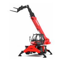
Manitou M30 40 50 Forklift Truck Wiring Diagrams
Manitou M30 40 50 Forklift Truck Wiring Diagrams
Manitou M30 40 50 Forklift Truck Wiring
Adobe Acrobat Document
408.6 KB
![]()
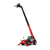
Manitou Forklift Service Manual
Manitou Fork Service Manual
Manitou Fork Service Manual.pdf
Adobe Acrobat Document
2.1 MB
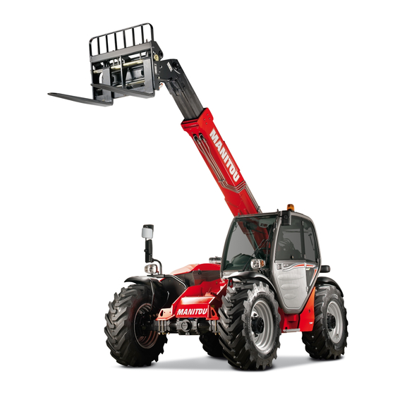
![]()
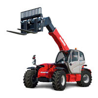
Manitou MLT735 Operator Manual
Manitou MLT735 Operator Manual
Manitou MLT735 Operator Manual.pdf
Adobe Acrobat Document
3.3 MB
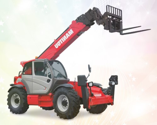
![]()
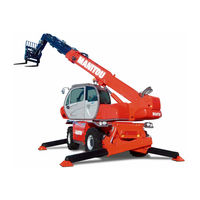
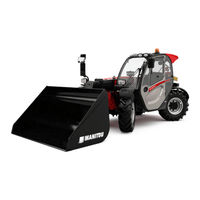
Manitou MTL845 945 Telehandler Operator’s Manual PDF
Manitou MTL845 945 Telehandler Operator’s Manual PDF
Manitou MTL845 945 Telehandler Operator’
Adobe Acrobat Document
3.8 MB
![]()
Manitou MLA628 Telehandler Operator’s Manual PDF
Manitou MLA628 Telehandler Operator’s Manual PDF
Manitou MLA628 Telehandler Operator’s Ma
Adobe Acrobat Document
3.3 MB
![]()
Manitou MLT625 Telehandler Operator’s Manual PDF
Manitou MLT625 Telehandler Operator’s Manual PDF
Manitou MLT625 Telehandler Operator’s Ma
Adobe Acrobat Document
4.9 MB
Some MANITOU Forklift Truck and Telehandler Service Manuals PDF, Wiring Diagrams & Error Codes DTC are above the page.
The history of Manitou began in 1958, it was then that the founder of the Manitou concern, Marcel BRO, used an engineering solution that was
quite extraordinary for that time, attaching a lifting mast to an agricultural tractor, and he created the first Manitou mast-lift with off-road capability.
Today, the Company produces more than 300 models of loading equipment, including exclusive models that have no analogues in the world.
Manitou is the world leader in the design and development of telescopic loaders, warehouse equipment and off-road loaders.
The Manitou technique is used in many sectors of the world economy.
Manitou offers unique solutions for the mining industry — the Manitou
Mining line. Manitou telescopic handlers help worldwide to quickly and efficiently repair mining equipment and to perform
mining operations more efficiently and safely.
Manitou Construction, Manitou loaders are designed for lifting, transporting various
types of cargo and personnel to great heights, in areas of construction objects that are difficult to reach for cargo delivery.
With its compact size and high maneuverability, complete with a telescopic boom, Manitou loaders deliver cargo not only vertically, to
certain heights, but also horizontally.
This technical capability of the telescopic boom developed and created by engineers of the Manitou concern can significantly reduce
labor costs associated with moving heavy loads and optimize the construction time of various objects.