- Manuals
- Brands
- Lowrance Manuals
- Fish Finder
- ELITE TI
- Installation manual
-
Contents
-
Table of Contents
-
Bookmarks
Quick Links
ELITE Ti
Installation Manual
ENGLISH
lowrance.com
Related Manuals for Lowrance ELITE TI
Summary of Contents for Lowrance ELITE TI
-
Page 1
ELITE Ti Installation Manual ENGLISH lowrance.com… -
Page 3
In case of any queries, refer to the brand website of your unit or system: lowrance.com. Regulatory statements This equipment is intended for use in international waters as well as coastal sea areas administered by the USA, and countries of the E.U. and E.E.A. Preface | ELITE Ti Installation Manual… -
Page 4
However, there is no guarantee that the interference will not occur in a particular installation. If this equipment does cause harmful interference to radio or television reception, which can be determined by turning the equipment off Preface | ELITE Ti Installation Manual… -
Page 5
LV — Latvia LI — Liechtenstein LT — Lithuania LU — Luxembourg MT — Malta NL — Netherlands NO — Norway PL — Poland PT — Portugal RO — Romania SK — Slovak Republic Preface | ELITE Ti Installation Manual… -
Page 6
This manual refers to the following Navico products: • Broadband Sounder™ (Broadband Sounder) • DownScan Overlay™ (Overlay) • GoFree™ (GoFree) • INSIGHT GENESIS® (Insight Genesis) • StructureMap™ (StructureMap) • StructureScan® (StructureScan) • StructureScan® HD (StructureScan HD) Preface | ELITE Ti Installation Manual… -
Page 7: About This Manual
About this manual This manual is a reference guide for installing the ELITE Ti. Important text that requires special attention from the reader is emphasized as follows: Note: Ú Used to draw the reader’s attention to a comment or some important information.
-
Page 8
Preface | ELITE Ti Installation Manual… -
Page 9: Table Of Contents
NMEA 2000 backbone NMEA 0183 device connection 31 Software Setup First time startup Time and Date Data source selection Device list Diagnostics Damping Sonar setup StructureScan Autopilot setup Fuel setup Wireless setup Bluetooth wireless technology Contents | ELITE Ti Installation Manual…
-
Page 10
Software updates and data backup 50 Accessories NMEA 2000 ELITE Ti accessories Sonar accessories 52 Supported data NMEA 2000 compliant PGN List NMEA 0183 supported sentences 58 Specifications 60 Dimensional drawings ELITE-5Ti Dimensional drawings ELITE-7Ti Dimensional drawings Contents | ELITE Ti Installation Manual… -
Page 11: Check The Contents
Fuse holder (ATC blade) Quick release mounting bracket Fuse (3 amp) Quick release mounting bracket screws (4 x #10 x 3/4 PN HD SS screws) Bracket locking bolt and knob. (ELITE-7Ti only) 10 Documentation pack Check the contents | ELITE Ti Installation Manual…
-
Page 12: Overview
The unit is intended for 12 V DC operation and will accept the moderate fluctuations commonly seen in DC systems. Front controls Touch screen Pages Zoom out / Zoom in (combined press = MOB) Overview | ELITE Ti Installation Manual…
-
Page 13: Rear Connections
Press and hold to turn the unit ON/OFF. Press once to display the System Controls dialog. Card reader (behind logo) Rear connections ELITE-5Ti rear connections Sonar — CHIRP, Broadband, DownScan and SideScan imaging Power (12 V supply input) and NMEA 0183 Overview | ELITE Ti Installation Manual…
-
Page 14: Card Reader
Used for attaching a microSD memory card. The memory card can be used for detailed chart data, software updates, transfer of user data, and system backup. The card reader door is opened by flipping back the logo and pulling the rubber cover open. Overview | ELITE Ti Installation Manual…
-
Page 15
The card reader door should always be securely shut immediately after inserting or removing a card, in order to prevent possible water ingress. Overview | ELITE Ti Installation Manual… -
Page 16: Installation
For overall width and height requirements, refer to «Dimensional drawings» on page 60. Choose a location that will not expose the unit to conditions that exceed the IP rating — refer to «Specifications» on page 58. Installation | ELITE Ti Installation Manual…
-
Page 17: Quick Release Bracket Mounting
If the material is too thin for self-tappers, reinforce it, or mount the bracket with machine screws and large washers. Use only 304 or 316 stainless steel fasteners. Screw down the bracket. Snap the unit to the bracket. Installation | ELITE Ti Installation Manual…
-
Page 18
Tilt the unit to the desired position angle. For ELITE-7Ti only, set the desired angle and then insert the locking bolt and knob. Tighten to stop angle movement Installation | ELITE Ti Installation Manual… -
Page 19: Panel Mount
Using a fingernail or small flat screwdriver, pry off the corner clips at the slotted points located at the top or bottom of each corner clip. Installation | ELITE Ti Installation Manual…
-
Page 20
Secure the unit with screws (not supplied). For recommended screw size and type, refer to the mounting template. Once screws are fully tightened, ensure there is complete contact with the mounting surface. Press the four corner clips back into position. Installation | ELITE Ti Installation Manual… -
Page 21
Installation | ELITE Ti Installation Manual… -
Page 22: Mounting The Transducer
Select a transducer location The primary aim is to stay clear of propeller and hull generated turbulence, while mounting the transducer as close to the center of the vessel as possible. Mounting the transducer | ELITE Ti Installation Manual…
-
Page 23
Note: Ú Trim tabs vary in the amount of turbulence they create as they are adjusted, stay clear of these. Mounting the transducer | ELITE Ti Installation Manual… -
Page 24: Attaching The Transducer
Attach transducer to transom, using supplied stainless steel fasteners. Drill a 25 mm (1”) hole above the waterline, large enough to pass the plug through. Mounting the transducer | ELITE Ti Installation Manual…
-
Page 25: Adjusting The Transducer
If performance does not improve with tilting, try adjusting the height of the transducer relative to the transom of the boat. If the transducer is too high it may be seeing cavitation caused by the trailing edge of the transom. Mounting the transducer | ELITE Ti Installation Manual…
-
Page 26: Wiring
24 V DC systems. Warning: The positive supply wire (red) should always be connected to (+) DC with the supplied fuse or a circuit breaker (closest available to fuse rating). Wiring | ELITE Ti Installation Manual…
-
Page 27: Power Connection
Vessel’s 12 V DC supply NMEA 0183 cable The unit can be powered on and off using the power button on the front of the unit. Transducer connection The unit has internal CHIRP, Broadband, and StructureScan sonar. Wiring | ELITE Ti Installation Manual…
-
Page 28: Nmea 2000 Backbone
T-connector or 4-way connector. Power the network The network requires its own 12 V DC power supply protected by a 3 amp fuse or breaker. Connect power at any location in the backbone for smaller systems. Wiring | ELITE Ti Installation Manual…
-
Page 29
The following drawing demonstrates a typical small network. The backbone is made up of directly interconnected T-connectors. 12 V DC NMEA 2000 device Connector to unit Drop-cable, should not exceed 6 m (20 ft) Terminators Backbone Power cable Wiring | ELITE Ti Installation Manual… -
Page 30: Nmea 0183 Device Connection
The output (TX) however may drive multiple receivers (Listeners). The number of receivers is finite, and depends on the receiving hardware. Typically three devices is possible. Wiring | ELITE Ti Installation Manual…
-
Page 31: Software Setup
You can perform further setup using the system settings option and later change settings made with the setup wizard. Time and Date Configure time settings to suit vessel location, along with time and date formats. Software Setup | ELITE Ti Installation Manual…
-
Page 32: Data Source Selection
Note: Ú Auto data source selection may already have been selected at first time startup, however it should be redone if any new devices have been added to the network since. Software Setup | ELITE Ti Installation Manual…
-
Page 33
Selecting Reset Local reverts all data source selections on the unit being used to the Global source settings available from other networked units. Software Setup | ELITE Ti Installation Manual… -
Page 34: Device List
Setting the instance number on a 3rd party product is typically not possible. Diagnostics Diagnostics are available on the ELITE-7Ti only. The NMEA 2000 tab on the diagnostics page can provide information useful for identifying an issue with the network. Software Setup | ELITE Ti Installation Manual…
-
Page 35
Rx/Tx Messages Shows actual traffic in and out of device. Bus Load A high value here indicates network is near full capacity. Some devices automatically adjust rate of transmission, if network traffic is heavy. Software Setup | ELITE Ti Installation Manual… -
Page 36: Damping
As a result, water depth readings do not account for the distance from the transducer to the lowest point of the boat (for example; bottom of the keel, rudder, or propeller) in the water or from the transducer to the water surface. Software Setup | ELITE Ti Installation Manual…
-
Page 37: Transducer Type
Transducer temperature sensors are one of two impedances — 5k or 10k. Where both options are Software Setup | ELITE Ti Installation Manual…
-
Page 38: Structurescan
Vessel setup is available on the ELITE-7Ti only. The Vessel setup dialog must be used to select the number of engines, the number of tanks and vessel’s total fuel capacity across all tanks. Software Setup | ELITE Ti Installation Manual…
-
Page 39
Calibrating fuel flow is available on the ELITE-7Ti only. Calibration may be required to accurately match measured flow with actual fuel flow. Access calibration from the Refuel dialog. Calibration is only possible on Navico’s Fuel Flow sensor. Software Setup | ELITE Ti Installation Manual… -
Page 40
The number of tanks must be set in Vessel Setup dialog, initiated from the Fuel setting options page, to allow discrete tank assignment of the Fluid Level devices. Software Setup | ELITE Ti Installation Manual… -
Page 41: Wireless Setup
Enter the eight character (or longer) Network Key in the tablet to connect to the network. Open the GoFree application — the unit should be automatically detected. The name displayed will be either the default, or that Software Setup | ELITE Ti Installation Manual…
-
Page 42
This menu also allows disconnection of devices that no longer require access. Wireless device This page shows the internal wireless module and its IP and channel number. Software Setup | ELITE Ti Installation Manual… -
Page 43
The application must be installed on and run from a tablet device. The ELITE Ti must be running Iperf server before initiating the test from the tablet. On exiting the page, Iperf automatically stops running. -
Page 44: Bluetooth Wireless Technology
DHCP servers on a network, dhcp_probe may be run from the ELITE Ti. Only one DHCP device may be operational on the same network at a time. If a second device is found, turn off its DHCP feature if possible.
-
Page 45: Nmea 0183 Setup
NMEA 0183 input and output. The input and output (Tx, Rx) use the same baud rate setting. Note: Ú AIS transponders typically operate at NMEA 0183-HS (high speed), and will require the baud rate to be set to 38,400. Software Setup | ELITE Ti Installation Manual…
-
Page 46: Touchscreen Calibration
Ensure the screen is clean and dry before doing the calibration. Do not touch the screen unless prompted to do In some cases it may be required to re-calibrate the touch screen. To re-calibrate your touchscreen, do the following: Software Setup | ELITE Ti Installation Manual…
-
Page 47: Software Updates And Data Backup
Updates can be found on the website: lowrance.com The unit may be used to apply software updates to itself, and to supported network devices, with files read off a memory card inserted in the card reader.
-
Page 48
User data file version 5: Use with current units (NSO evo2, NSS • evo2, NSS, NSO, NSE, Zeus, Zeus Touch, HDS Gen2, HDS Gen2 Touch, HDS Gen3, GO XSE units, Vulcan units, and ELITE Ti units). Offers most detail. User data file version 4: Use with current units (NSO evo2, NSS •… -
Page 49: Software Upgrades
If no device is shown, check that the device to be updated has power, and run any outstanding updates for the unit first. Select the device and initiate the upgrade. Do not interrupt the upgrade process. Software Setup | ELITE Ti Installation Manual…
-
Page 50: Accessories
000-10613-001 RC42 Rate compass ELITE Ti accessories Part number Description 000-10027-001 Quick release mounting bracket kit 000-0127-49 Power and NMEA 0183 Cable 000-12750-001 Sun cover for the ELITE-5Ti 000-12749-001 Sun cover for the ELITE-7Ti Accessories | ELITE Ti Installation Manual…
-
Page 51: Sonar Accessories
In-hull shoot-thru transducer, depth only* 000-0106-89 In-hull, shoot-thru transducer, depth and remote temperature* 000-12572-001 7-pin transducer to 9-pin adapter cable * Require the 000-12572-001 7-pin transducer to 9-pin adapter cable For additional transducer options, visit www.lowrance.com Accessories | ELITE Ti Installation Manual…
-
Page 52: Supported Data
126208 ISO Command Group Function 126992 System Time 126996 Product Info 127237 Heading/Track Control 127245 Rudder 127250 Vessel Heading 127251 Rate of Turn 127257 Attitude 127258 Magnetic Variation 127488 Engine Parameters, Rapid Update 127489 Engine Parameters, Dynamic Supported data| ELITE Ti Installation Manual…
-
Page 53
129283 Cross Track Error 129284 Navigation Data 129539 GNSS DOPs 129540 GNSS Sats in View 129794 AIS Class A Static and Voyage Related Data 129801 AIS Addressed Safety Related Message 129802 AIS Safety Related Broadcast Message Supported data| ELITE Ti Installation Manual… -
Page 54
130839 Pressure Insect Configuration 130840 Data User Group Config 130842 AIS and VHF Message Transport 130843 Sonar Status – Frequency and DSP Voltage 130845 Weather and Fish Prediction and Barometric Pressure History 130850 Evinrude Engine Warnings Supported data| ELITE Ti Installation Manual… -
Page 55
129283 Cross Track Error 129284 Navigation Data 129285 Route/Waypoint Data 129539 GNSS DOPs 129540 GNSS Sats in View 130074 Route and WP Service — WP List — WP Name & Position 130306 Wind Data Supported data| ELITE Ti Installation Manual… -
Page 56: Nmea 0183 Supported Sentences
130845 Weather and Fish Prediction and Barometric Pressure History 130850 Evinrude Engine Warnings 130851 Parameter (RC42 Compass and IS12 Wind Calibration and Configuration) NMEA 0183 supported sentences TX / RX — GPS Receive Transmit TX / RX — Navigation Receive Transmit Supported data| ELITE Ti Installation Manual…
-
Page 57
TX / RX — Compass Receive Transmit TX / RX — Wind Receive Transmit TX / RX — AIS / DSC Receive Note: Ú AIS sentences are not bridged to or from NMEA 2000. Supported data| ELITE Ti Installation Manual… -
Page 58: Specifications
Processor iMX61 single core Conformity CE, C-Tick Interfaces NMEA 2000 (compliant). 1 port — Micro-C male. ELITE-7Ti ELITE-7Ti only. only. NMEA 0183 (compliant) 1 port — Power 12 V DC and Data — NMEA 0183 Specifications| ELITE Ti Installation Manual…
-
Page 59
Sonar 1 port Card reader 1 x microSD Specifications| ELITE Ti Installation Manual… -
Page 60: Dimensional Drawings
33.5 mm (1.10”) (1.31”) 94.0 mm 94.0 mm (3.70”) (3.70”) 113.5 mm (4.46”) ELITE-7Ti Dimensional drawings 219.50 mm (8.70”) 28.0 mm 36.0 mm (1.10”) (1.42”) 94.0 mm 94.0 mm (3.70”) (3.70”) 117.0 mm (4.60”) Dimensional drawings| ELITE Ti Installation Manual…
-
Page 62
0980…
Прошивки и инструкции для эхолотов Lowrance/
-
#1
Предлагаю в этой теме выкладывать только инструкции, прошивки и прочие полезности. В идеале без обсуждений. Просто описание и собственно сам файл или ссылка на диск. (Если конечно это не возбраняется на данном форуме) Думаю многие новички скажут спасибо за ссылки. А старожилам не нужно будет отправлять новичков пользоваться поиском. Для начала выкладываю ссылку на Яндекс диск с прошивками которые у меня есть. https://yadi.sk/d/rDC6IQCqkurLxQ?w=1
Прошивки и инструкции для эхолотов Lowrance/
-
#2
Добавлю инструкцию на лайв. У кого то скачивал. Не прицепился большой файл.
Прошивки и инструкции для эхолотов Lowrance/
-
#3
Хотелось бы ещё инструкцию как правильно установить новую прошивку. Делать резет до или после, с сохранением точек и настроек, в общем с нуля для чайников.
Прошивки и инструкции для эхолотов Lowrance/
-
#4
Последнее редактирование:
Прошивки и инструкции для эхолотов Lowrance/
-
#5
Прошивки и инструкции для эхолотов Lowrance/
-
#6

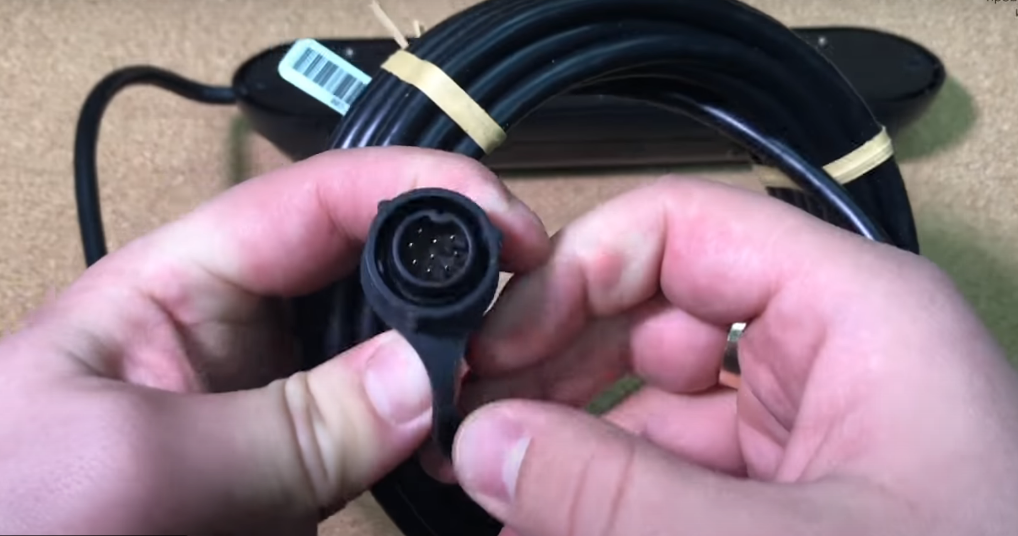
а зачем в этом разьеме плюс и минус? в ответной фишке на моторе только кан.
Прошивки и инструкции для эхолотов Lowrance/
-
#7
Я кстати в этом разьеме на пин 1 припаял экран витой пары .Думаю так надежнее.
Прошивки и инструкции для эхолотов Lowrance/
-
#8
только резистор не 120 а 60 ом
Прошивки и инструкции для эхолотов Lowrance/
-
#9
только резистор не 120 а 60 ом
это если сеть занята только мотором…
Прошивки и инструкции для эхолотов Lowrance/
-
#10
а зачем в этом разьеме плюс и минус? в ответной фишке на моторе только кан.
фото выкладывалось для понимания какой разьем искать. А подключение конечно только два провода надо, как на схеме. Скорее всего это провод для подключения в хаб. Точно утверждать не могу. И резисторы нужны если напрямую к эхолоту. А если в Т-коннектор сети, то там уже есть по краям они.
Прошивки и инструкции для эхолотов Lowrance/
-
#11
Инструкция к Elit TI 7-9 . Для ТИ-2 тоже подходит.Вдруг кому пригодится.
-
3.6 МБ
· Просмотры: 861
Elite7-9Ti_инструкция_ru.pdf
Прошивки и инструкции для эхолотов Lowrance/
-
#12
Еще интструкция для HOOK 2 на русском.Не много корявенький перевод но разобраться можно.
-
7.4 МБ
· Просмотры: 3 561
Hook2-Series-RUS.pdf
Прошивки и инструкции для эхолотов Lowrance/
-
#13
Предлагаю в этой теме выкладывать только инструкции, прошивки и прочие полезности. В идеале без обсуждений. Просто описание и собственно сам файл или ссылка на диск. (Если конечно это не возбраняется на данном форуме) Думаю многие новички скажут спасибо за ссылки. А старожилам не нужно будет отправлять новичков пользоваться поиском. Для начала выкладываю ссылку на Яндекс диск с прошивками которые у меня есть. https://yadi.sk/d/rDC6IQCqkurLxQ?w=1
Добавил прошивки на элиты и карбоны еще.
Прошивки и инструкции для эхолотов Lowrance/
-
#14
Вопрос — на карбон после прошивки 19.1 114 сразу была 153 или между ними еще прошивки были?
Прошивки и инструкции для эхолотов Lowrance/
-
#15
Вопрос — на карбон после прошивки 19.1 114 сразу была 153 или между ними еще прошивки были?
у меня больше нет. Владельцы карбонов дополнят надеюсь.
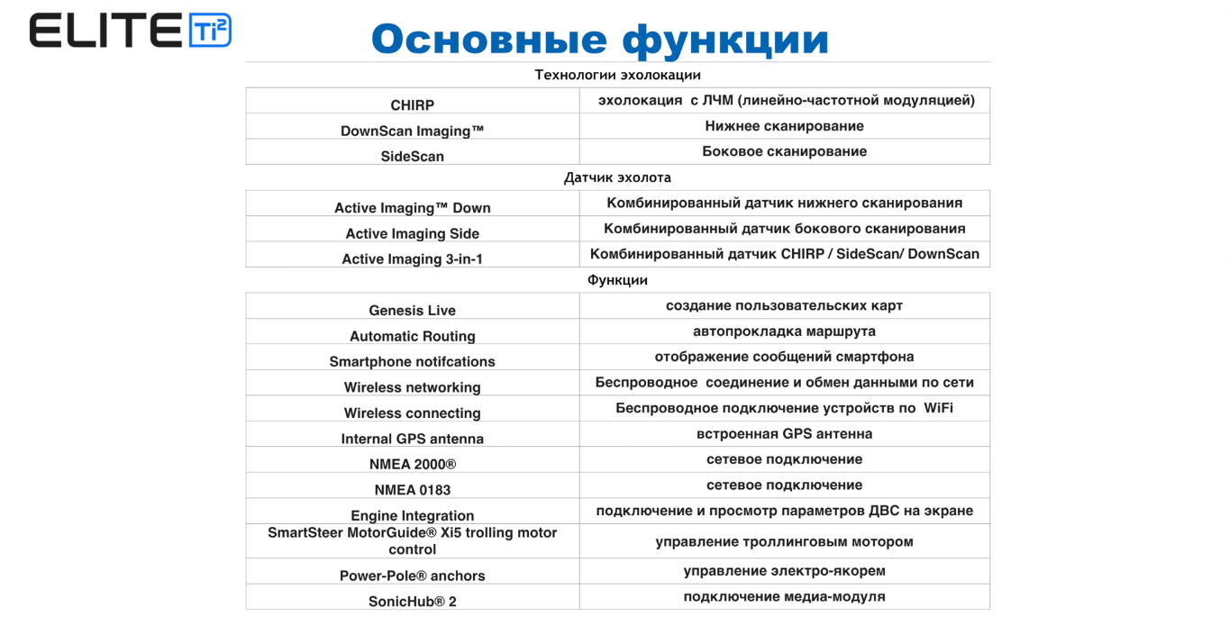
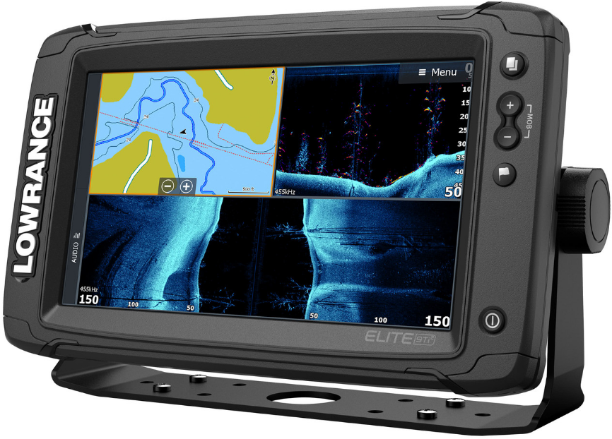
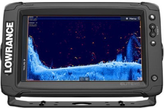
Эхолот-картплоттер Lowrance Elite 9 Ti2 — это доступное по цене устройство, которое оснащено теми функциями, которые обычно присутствуют в моделях премиум-класса.
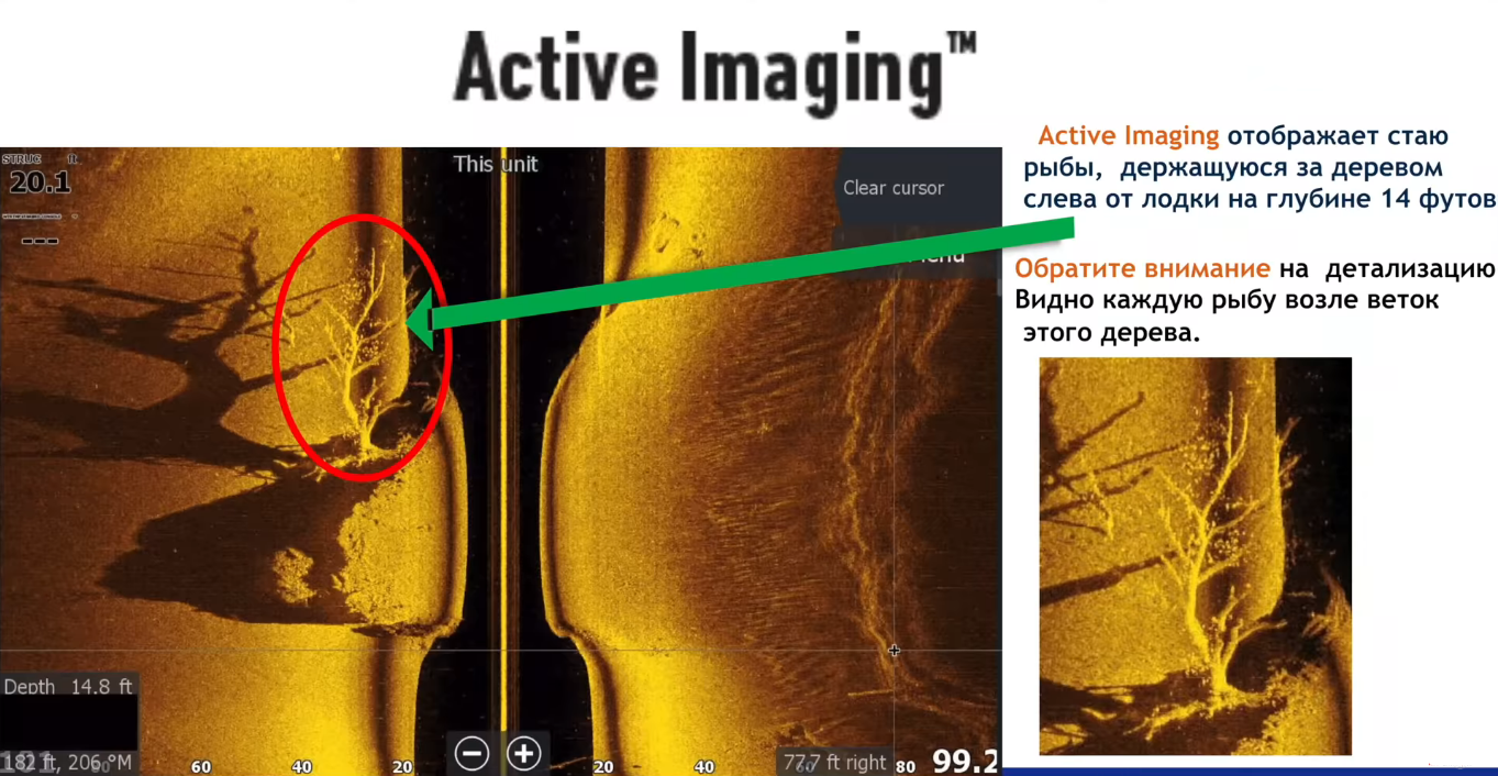
Так, у прибора есть технология Active Imaging 3в1 (сканирующая водоем и имеющая высокую детализацию изображения), функция обнаружения рыб, картография в реальном времени.
5%скидка
Для читателей нашего блога
скидка 5% на весь
ассортимент
Ваш промокод:BLOGСмотреть все эхолоты
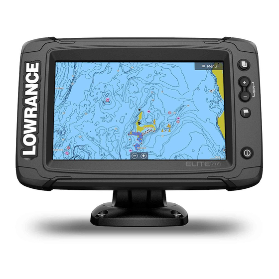
При этом эхолот имеет сенсорный дисплей с диагональю 9″, подсветкой и высоким разрешением 800х480 пикселей.
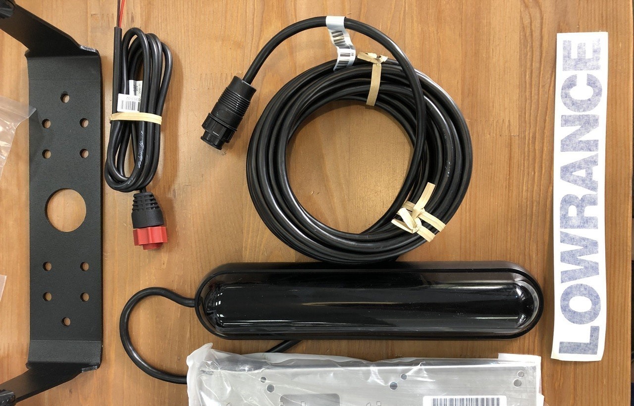
Комплектация
Приходит устройство в картонной коробке, на которой размещен логотип производителя и указаны краткие технические характеристики.
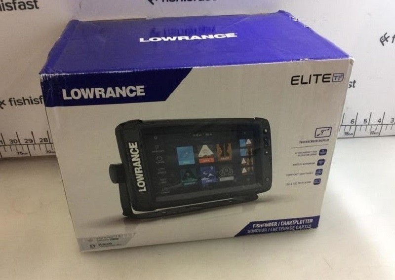
Внутри находятся:
- дисплей;
- защитная крышка;
- комплекты крепежа;
- многофункциональный датчик;
- крепление для датчика;
- подставка под дисплей (в форме буквы U);
- инструкции;
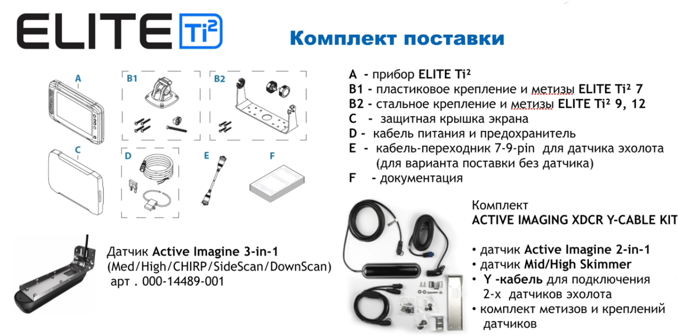
- кабель для зарядки;
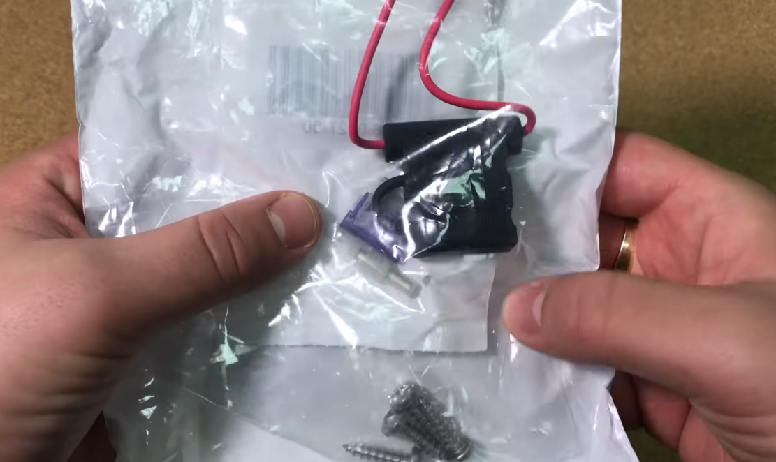
- предохранители от скачков мотора.
Дисплей надежно прикреплен к внутренней части коробки. Остальные составляющие сложены в полиэтилен.
Инструкция
Инструкция представлена в виде небольшой книжки. На русском языке текст не представлен. Производитель проводит работы по подготовке русскоязычной документации, однако они пока не завершены.

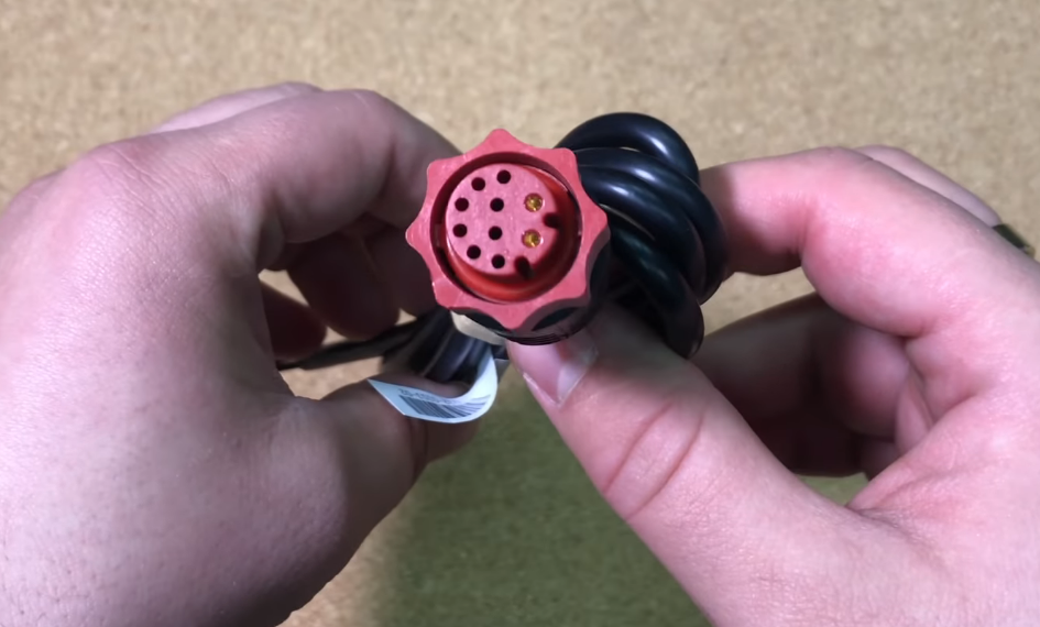
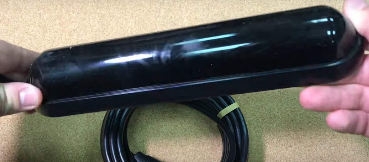
Кабель зарядки
Кабель, позволяющий зарядить устройство, имеет вид многожильного провода в водонепроницаемой и толстой оплетке. Как и остальные комплектующие, он упакован в отдельный полиэтиленовый пакет.
")
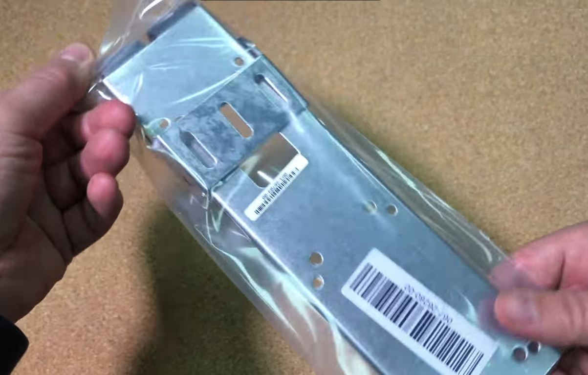
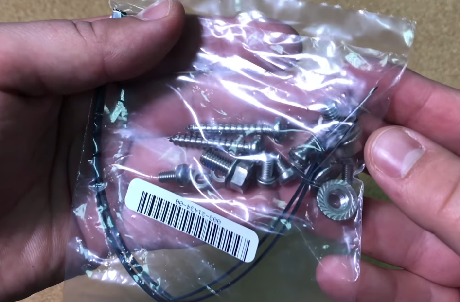
Комплект крепежа
В плотном пакете поставляются хомуты, саморезы, шайбы, барашки и болты — то есть все те элементы, которые необходимы для крепления частей эхолота. Болты с саморезами хромированы и имеют антикоррозийное покрытие.
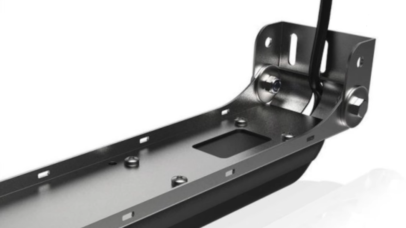
Также производитель добавил в общий комплект деталей специальную металлическую планку, к которой будет крепиться датчик устройства. Она более надежна, в сравнении с пластиковыми планками, которые компания изготавливала для ранних моделей эхолотов. А еще на ней лучше видны различные деформации, что позволяет вовремя определить неисправность.
Подставка для дисплея
Подставка сделана в U-образной форме. На нее устанавливается экран устройства, который закрепляется с помощью винтов-барашков.
Зафиксированный дисплей можно поворачивать под разными углами, но только вертикально. Если есть желание также изменять угол обзора и в горизонтальной плоскости, понадобится купить другой тип крепления.
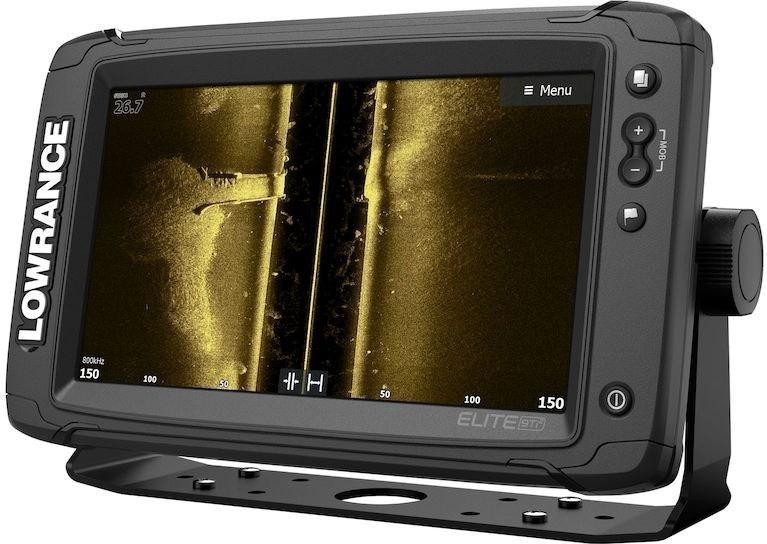
Многофункциональный датчик
Этот датчик носит название Active Imaging 3-in-1. Он в одной системе объединяет 3 совершенно разных функциональных элемента:
- Стандартный двулучевой эхолот.
- Датчик для нижнего сканирования.
- Датчик для бокового сканирования.
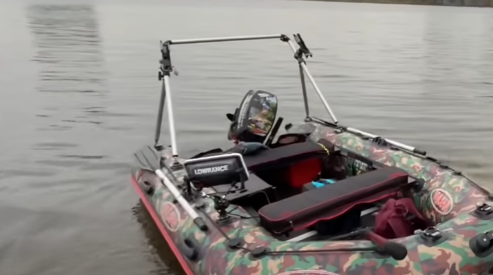
Следует заметить, что данный элемент имеет отнюдь не компактные размеры и иногда может выпирать за пределы лодки. В связи с этим устройство можно установить далеко не на каждое судно.
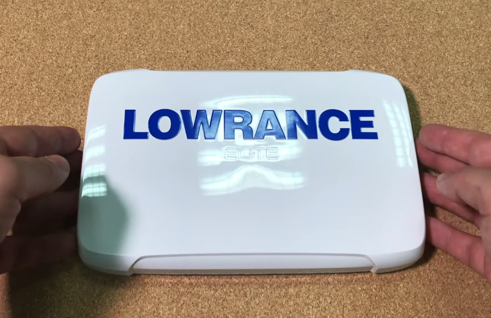
Дисплей и его крышка
Отдельно от экрана в полиэтилен упакована белая пластмассовая крышка, которая закрывает его и предотвращает вероятность повреждения.
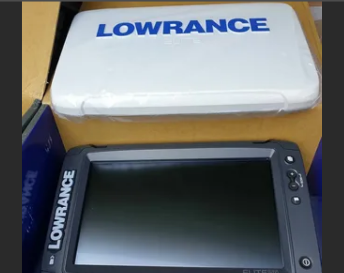
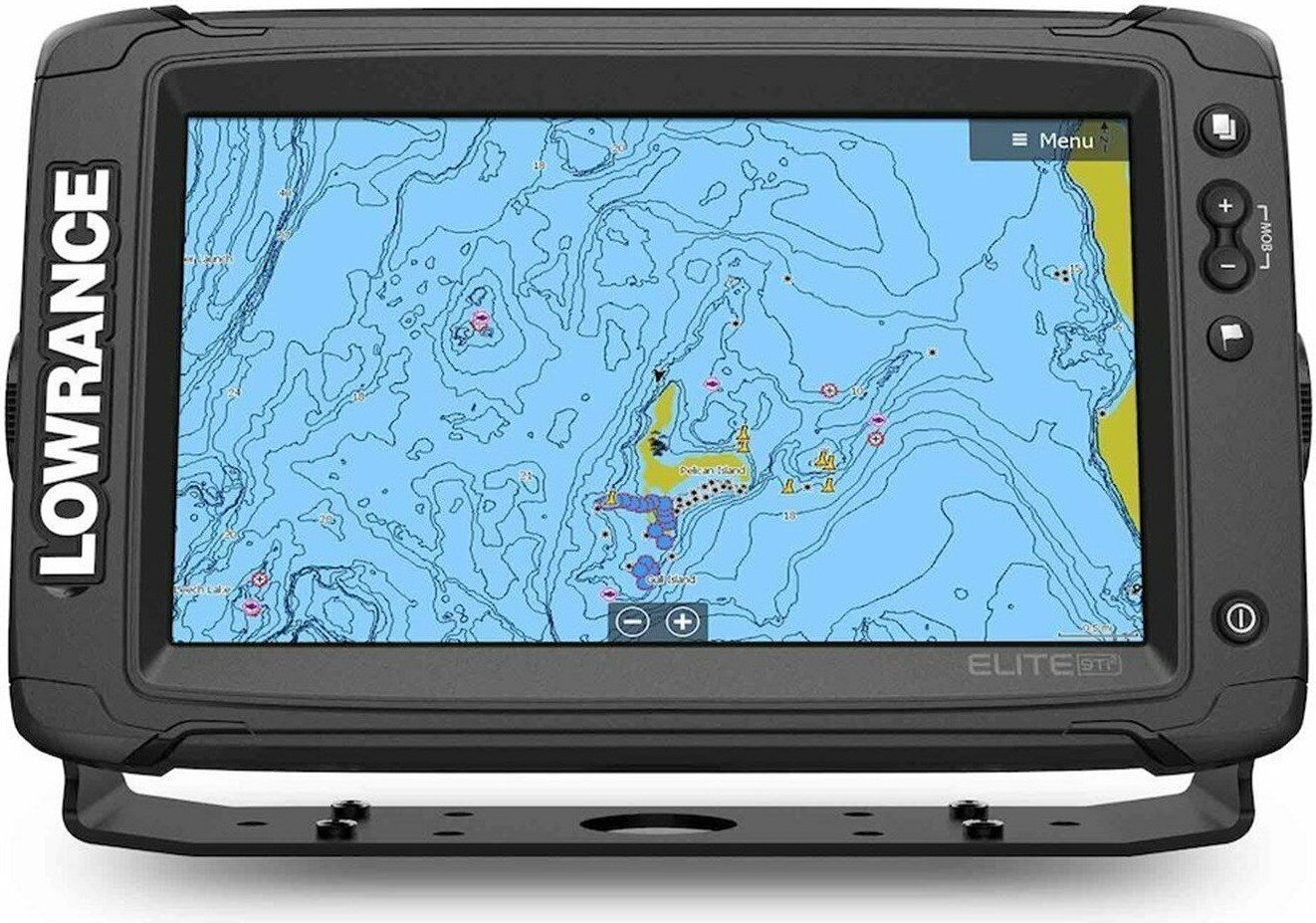
Сам сенсорный дисплей SolarMax довольно большой — по диагонали достигает почти 23 см. Основная часть управления осуществляется с его помощью, а некоторые функции включаются путем нажатия кнопок, расположенных рядом с экраном. В отличие от инструкции, меню сделано на русском языке.
Как отмечают пользователи, сенсор быстро реагирует на касания, работает без задержек.
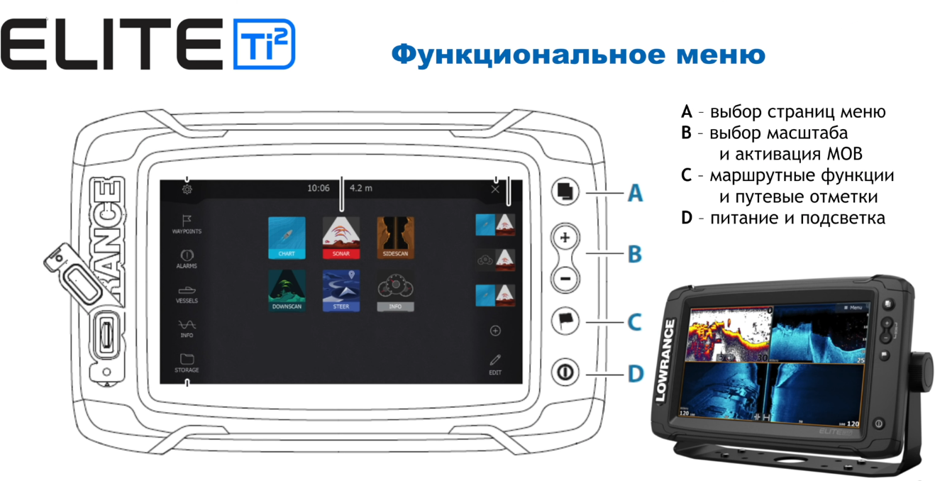
Экран яркий (1200 Нит), с хорошим контрастом и световосприятием. К тому же, на нем не появляется бликов от различных источников освещения (что удобно в солнечный день). У дисплея есть много различных режимов, которые позволяют выбрать подходящие настройки яркости, контраста и цвета.

Для удобства чтения информации в любое время суток имеется светодиодная подсветка. Сам дисплей водонепроницаемый (класса IPX7), разработан так, чтобы случайное попадание на него воды не повредило контакты и не привело к неисправности прибора.
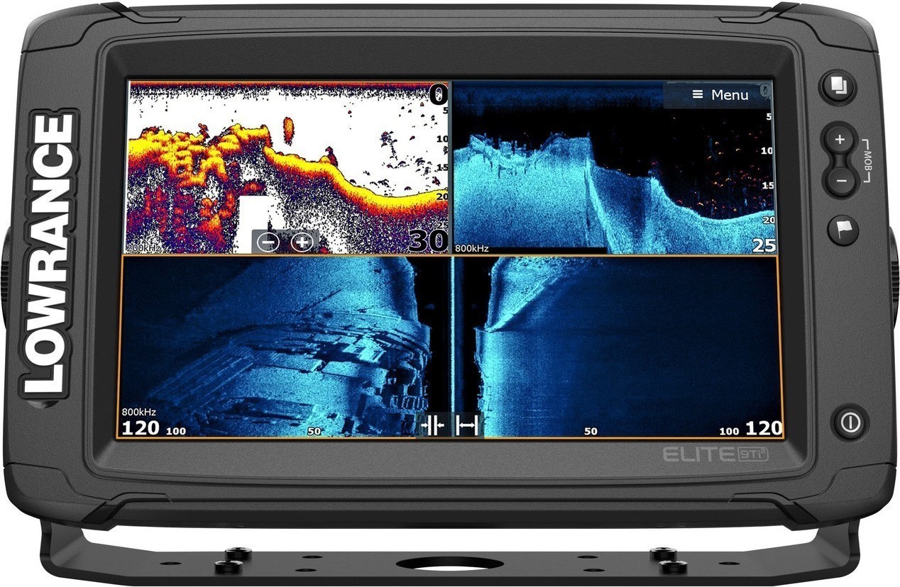
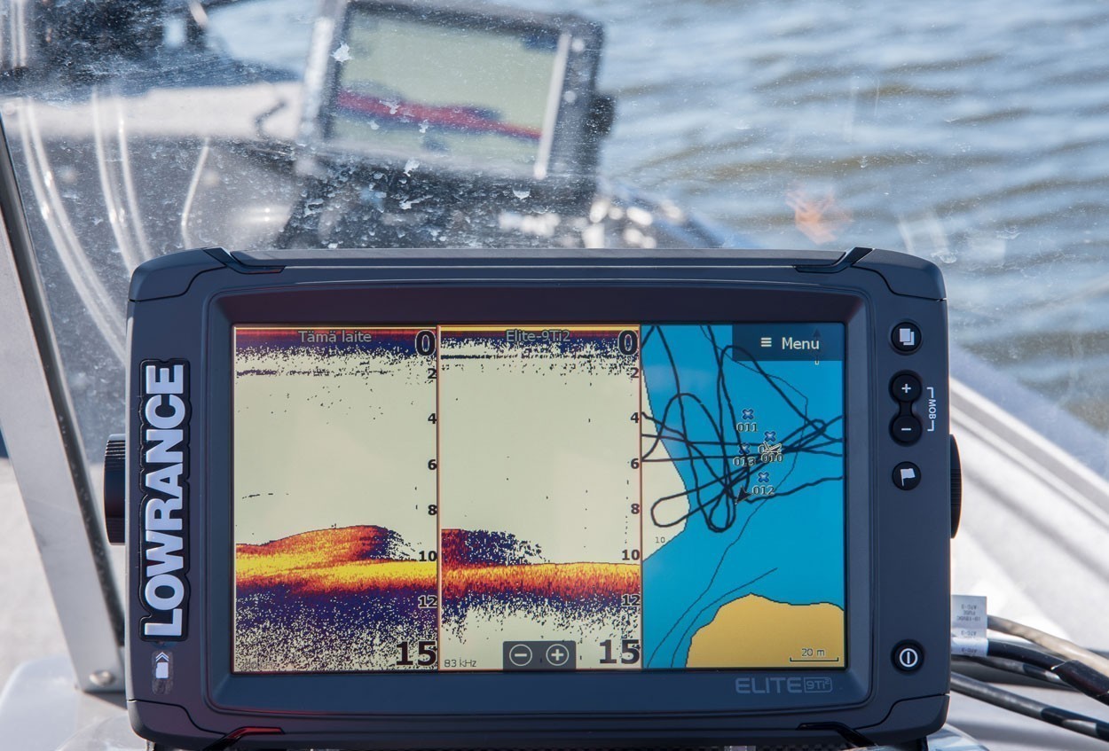
Экран можно разделить на несколько частей, а изображения — накладывать друг на друга. В целом, на нем хорошо отображаются перепады глубин и рыба, находящаяся поблизости, что очень важно в эхолоте.
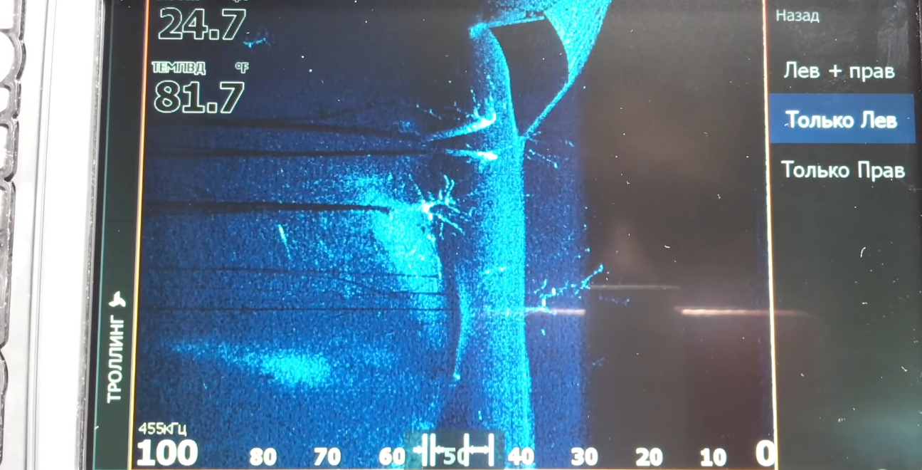
Функционал
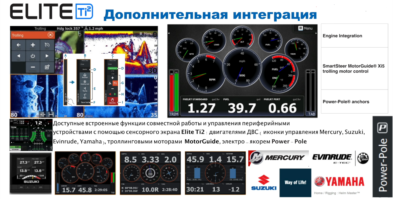
Главной функцией является сонар Active Imaging 3в1 (DownScan, SideScan, CHIRP) и 2в1 (DownScan, SideScan), поскольку все рыбопоисковые возможности с его помощью выходят на новый уровень. Он обеспечивает отличную детализацию и высокое разрешение изображения, а также (вне зависимости от диапазона сканирования) делает изображение четким и контрастным.
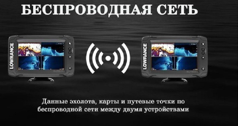
Эхолоты серии Elite Ti2 — первые, которые поддерживают беспроводное подключение. С их помощью можно обмениваться картами, точками, данными и маршрутами с другими устройствами этой серии без необходимости использовать кабель.
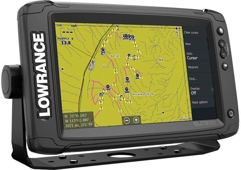
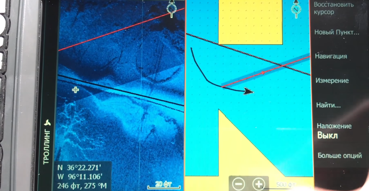
Помимо этого, данная модель прибора отличается мощными навигационными инструментами:
- загруженной базовой картой мира;
- поддержкой карт Navionics, C-MAP;
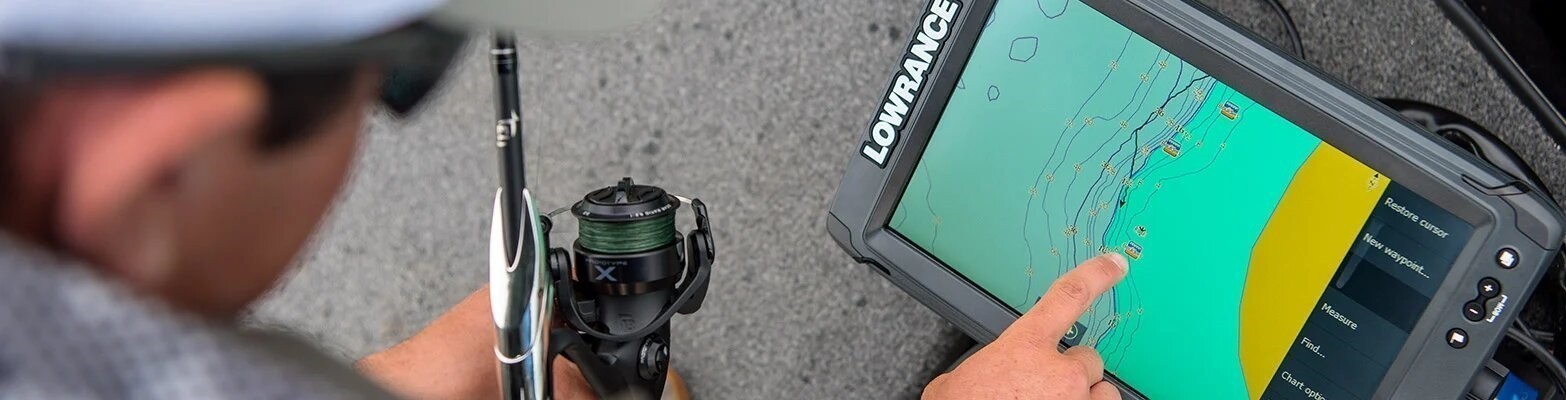
- созданием карт в реальном времени (Genesis Live).
С помощью последней функции можно самостоятельно создавать карты, которые будут отображать наиболее богатые рыбой места в реальном времени и подходящие, перспективные водоемы непосредственно на самом эхолоте. При этом точность прорисовки карт составляет до 15 см. В качестве дополнения прибор оснащен широкими возможностями настроек (к примеру, это изменение прозрачности контуров, цветовой палитры затемнения глубин, плотности контуров и др.).
Все карты, которые будут созданы, можно сохранить на внешний носитель памяти microSD.
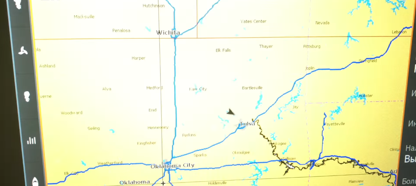
Возможность автоматического планирования маршрутов позволяет делать навигацию более легкой и быстрой. Активировать эту функцию можно через меню эхолота. В результате устройство автоматически проложит наиболее безопасный и короткий маршрут, обходящий возможные препятствия и мель в соответствии с данными о габаритах судна.
За счет того, что к прибору можно подключить свой телефон, на эхолот будут автоматически приходить уведомления — это не даст пропустить важное сообщение или срочный звонок в период нахождения на воде. Все оповещения отображаются на дисплее. Если же данная функция не нужна или даже мешает, то ее можно отключить в настройках.

Следующее, чем оснащена данная модель — это звуковая сигнализация. Это более надежный тип оповещения, чем графическая индикация, поскольку так пользователю не нужно постоянно смотреть на прибор. При этом он сможет по звуку вовремя узнать о критическом уменьшении глубины или выявлении рыбы, и тогда риск пропустить важное сообщение минимизируется.
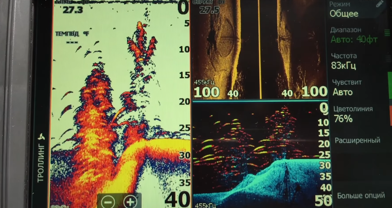
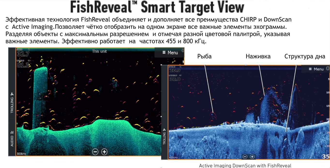
Также прибор осуществляет индикацию рыбы в реальном времени (FishReveal). Если предполагаемая добыча попадет под луч эхолота, сигналы будут отображаться на экране, а исчезнут, когда она уйдет.
Благодаря такой функции можно очень оперативно отслеживать перемещение водных обитателей и оценивать, насколько перспективна та или иная локация. Это существенное преимущество перед теми устройствами, которые не имеют индикации и отображают метки постоянно после обнаружения рыбы, что затрудняет оценку ее передвижения.
Также устройство способно и определить и глубину до живой цели.
Данная модель характеризуется быстрым обновлением экрана. От этого зависит, насколько равномерно на дисплее будет отображаться «видимый» прибором рельеф.
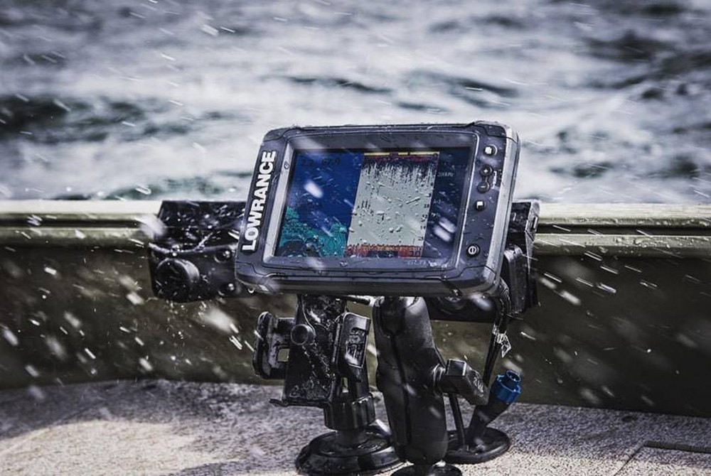
Такая способность эхолота особенно важна, когда движение осуществляется на большой скорости. Если экран медленно обновляется, то, вероятнее всего, будут появляться «ступеньки» с резкими перепадами, потому что устройство еще не успело обработать данные о пройденном участке дна и вывести их на дисплей.

Если же говорить о быстром обновлении, то в таком случае эхолот можно комфортно использовать даже на высокой скорости (не меньше 30–40 км/ч, которые развивают моторные лодки).
5%скидка
Для читателей нашего блога
скидка 5% на весь
ассортимент
Ваш промокод:BLOGСмотреть все эхолоты
Дополнительные функции
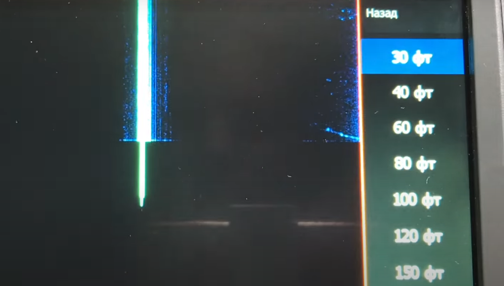
К вспомогательным функциям данной модели эхолота относятся:
- диапазон отображения глубины;
- индикация температуры воды;
- автоматическая смена масштаба глубины;
- отображение пройденного пути;
- определение плотности дна;
- индикация скорости;
- возможность загрузки новых навигационных карт;
- управление троллинговыми моторами MotorGuideXi5 и якорями Power-Pole.
Также в память эхолота можно загружать и сохранять до 3000 путевых точек, 100 треков и 100 маршрутов.
Беспроводные технологии
Модель эхолота Elite-9 Ti2 управляется с помощью сенсорного экрана и беспроводного либо Bluetooth-соединения. Благодаря беспроводной сети можно подключить свой прибор к интернету, чтобы получить доступ к базе данных GoFree для карт и обновлений программного обеспечения. А технология Bluetooth позволяет синхронизировать эхолот со смартфоном (для наблюдения) или планшетом (для дистанционного управления).
Технические характеристики
К основным техническим параметрам относятся:
- яркость экрана: 1200 Нит;
- разрешение дисплея: 800х480;
- GPS: 10 Гц GPS/MSAS/EGNOS/WAAS;
- напряжение питания: 12 В;
- вес: 1 кг;
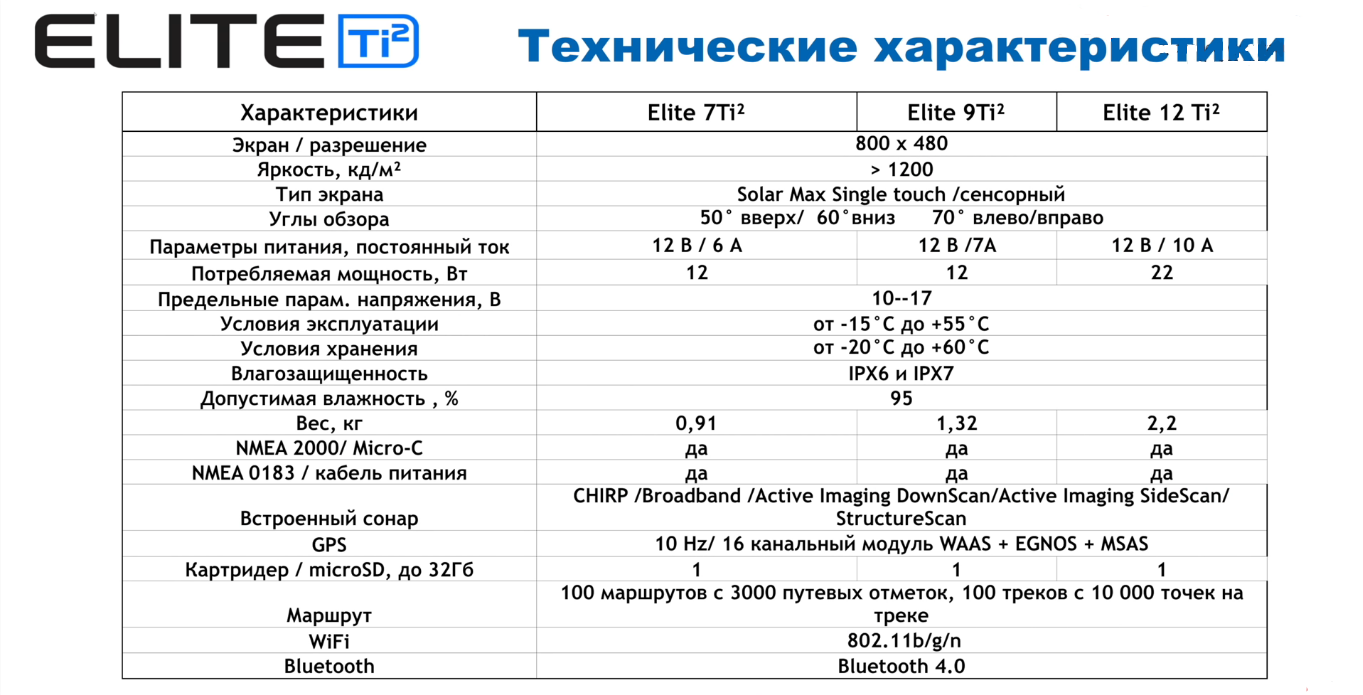
- SD-карта: 1 micro-карта до 32 Гб;
- внутренняя память: 8 Гб;
- температурный диапазон работы: от -20° до +60℃;
- канал приема GPS: 16;

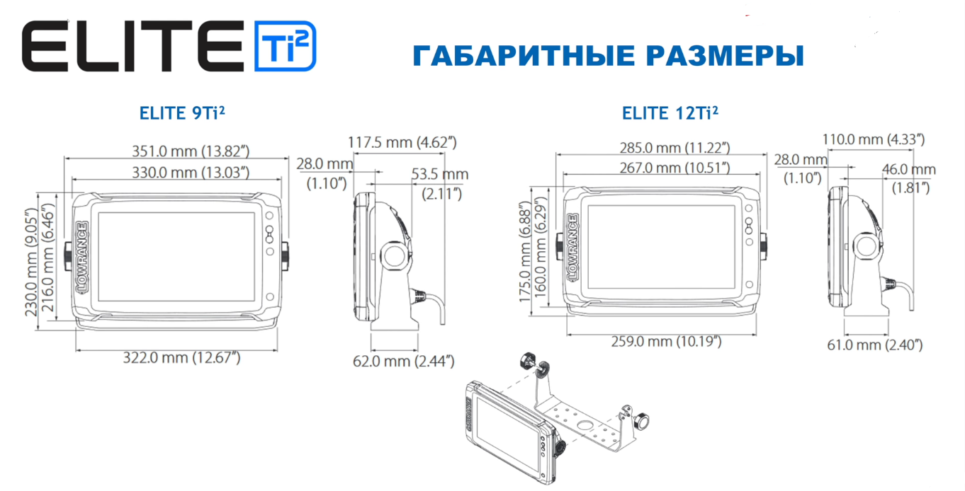
- размеры: 26,7×7,4×16 см;
- угол обзора: сверху/снизу — 80°, влево/вправо — 80°;
- тип монтажа: скоба крепления, встраивание в панель;
- Bluetooth: да (встроенный);
- водозащита: IPX7;
- количество лучей излучения: 2;
- Wi-Fi: да.
Рыбопоисковый эхолот-картплоттер Lowrance Elite-9 Ti2 — это современный прибор, позволяющий четко и быстро определить движение рыб, глубину и рельеф дна, построить собственные маршруты. Благодаря GPS-модулю и возможности устанавливать карту памяти пользователь может сохранять большое количество различных точек и треков. А большой, яркий и водонепроницаемый экран позволяет четко видеть изображения в любую погоду и легко управлять устройством.
Данный прибор отлично подойдет для пресноводной рыбалки, а также для рыбной ловли в море за счет эхолота с технологией CHIRP и хорошей рабочей глубины.
-
Page 1
ELITE Ti Installation Manual ENGLISH lowrance.com… -
Page 3
In case of any queries, refer to the brand website of your unit or system: lowrance.com. Regulatory statements This equipment is intended for use in international waters as well as coastal sea areas administered by the USA, and countries of the E.U. and E.E.A. Preface | ELITE Ti Installation Manual… -
Page 4
However, there is no guarantee that the interference will not occur in a particular installation. If this equipment does cause harmful interference to radio or television reception, which can be determined by turning the equipment off Preface | ELITE Ti Installation Manual… -
Page 5
LV — Latvia LI — Liechtenstein LT — Lithuania LU — Luxembourg MT — Malta NL — Netherlands NO — Norway PL — Poland PT — Portugal RO — Romania SK — Slovak Republic Preface | ELITE Ti Installation Manual… -
Page 6
This manual refers to the following Navico products: • Broadband Sounder™ (Broadband Sounder) • DownScan Overlay™ (Overlay) • GoFree™ (GoFree) • INSIGHT GENESIS® (Insight Genesis) • StructureMap™ (StructureMap) • StructureScan® (StructureScan) • StructureScan® HD (StructureScan HD) Preface | ELITE Ti Installation Manual… -
Page 7: About This Manual
About this manual This manual is a reference guide for installing the ELITE Ti. Important text that requires special attention from the reader is emphasized as follows: Note: Ú Used to draw the reader’s attention to a comment or some important information.
-
Page 8
Preface | ELITE Ti Installation Manual… -
Page 9: Table Of Contents
NMEA 2000 backbone NMEA 0183 device connection 31 Software Setup First time startup Time and Date Data source selection Device list Diagnostics Damping Sonar setup StructureScan Autopilot setup Fuel setup Wireless setup Bluetooth wireless technology Contents | ELITE Ti Installation Manual…
-
Page 10
Software updates and data backup 50 Accessories NMEA 2000 ELITE Ti accessories Sonar accessories 52 Supported data NMEA 2000 compliant PGN List NMEA 0183 supported sentences 58 Specifications 60 Dimensional drawings ELITE-5Ti Dimensional drawings ELITE-7Ti Dimensional drawings Contents | ELITE Ti Installation Manual… -
Page 11: Check The Contents
Fuse holder (ATC blade) Quick release mounting bracket Fuse (3 amp) Quick release mounting bracket screws (4 x #10 x 3/4 PN HD SS screws) Bracket locking bolt and knob. (ELITE-7Ti only) 10 Documentation pack Check the contents | ELITE Ti Installation Manual…
-
Page 12: Overview
The unit is intended for 12 V DC operation and will accept the moderate fluctuations commonly seen in DC systems. Front controls Touch screen Pages Zoom out / Zoom in (combined press = MOB) Overview | ELITE Ti Installation Manual…
-
Page 13: Rear Connections
Press and hold to turn the unit ON/OFF. Press once to display the System Controls dialog. Card reader (behind logo) Rear connections ELITE-5Ti rear connections Sonar — CHIRP, Broadband, DownScan and SideScan imaging Power (12 V supply input) and NMEA 0183 Overview | ELITE Ti Installation Manual…
-
Page 14: Card Reader
Used for attaching a microSD memory card. The memory card can be used for detailed chart data, software updates, transfer of user data, and system backup. The card reader door is opened by flipping back the logo and pulling the rubber cover open. Overview | ELITE Ti Installation Manual…
-
Page 15
The card reader door should always be securely shut immediately after inserting or removing a card, in order to prevent possible water ingress. Overview | ELITE Ti Installation Manual… -
Page 16: Installation
For overall width and height requirements, refer to «Dimensional drawings» on page 60. Choose a location that will not expose the unit to conditions that exceed the IP rating — refer to «Specifications» on page 58. Installation | ELITE Ti Installation Manual…
-
Page 17: Quick Release Bracket Mounting
If the material is too thin for self-tappers, reinforce it, or mount the bracket with machine screws and large washers. Use only 304 or 316 stainless steel fasteners. Screw down the bracket. Snap the unit to the bracket. Installation | ELITE Ti Installation Manual…
-
Page 18
Tilt the unit to the desired position angle. For ELITE-7Ti only, set the desired angle and then insert the locking bolt and knob. Tighten to stop angle movement Installation | ELITE Ti Installation Manual… -
Page 19: Panel Mount
Using a fingernail or small flat screwdriver, pry off the corner clips at the slotted points located at the top or bottom of each corner clip. Installation | ELITE Ti Installation Manual…
-
Page 20
Secure the unit with screws (not supplied). For recommended screw size and type, refer to the mounting template. Once screws are fully tightened, ensure there is complete contact with the mounting surface. Press the four corner clips back into position. Installation | ELITE Ti Installation Manual… -
Page 21
Installation | ELITE Ti Installation Manual… -
Page 22: Mounting The Transducer
Select a transducer location The primary aim is to stay clear of propeller and hull generated turbulence, while mounting the transducer as close to the center of the vessel as possible. Mounting the transducer | ELITE Ti Installation Manual…
-
Page 23
Note: Ú Trim tabs vary in the amount of turbulence they create as they are adjusted, stay clear of these. Mounting the transducer | ELITE Ti Installation Manual… -
Page 24: Attaching The Transducer
Attach transducer to transom, using supplied stainless steel fasteners. Drill a 25 mm (1”) hole above the waterline, large enough to pass the plug through. Mounting the transducer | ELITE Ti Installation Manual…
-
Page 25: Adjusting The Transducer
If performance does not improve with tilting, try adjusting the height of the transducer relative to the transom of the boat. If the transducer is too high it may be seeing cavitation caused by the trailing edge of the transom. Mounting the transducer | ELITE Ti Installation Manual…
-
Page 26: Wiring
24 V DC systems. Warning: The positive supply wire (red) should always be connected to (+) DC with the supplied fuse or a circuit breaker (closest available to fuse rating). Wiring | ELITE Ti Installation Manual…
-
Page 27: Power Connection
Vessel’s 12 V DC supply NMEA 0183 cable The unit can be powered on and off using the power button on the front of the unit. Transducer connection The unit has internal CHIRP, Broadband, and StructureScan sonar. Wiring | ELITE Ti Installation Manual…
-
Page 28: Nmea 2000 Backbone
T-connector or 4-way connector. Power the network The network requires its own 12 V DC power supply protected by a 3 amp fuse or breaker. Connect power at any location in the backbone for smaller systems. Wiring | ELITE Ti Installation Manual…
-
Page 29
The following drawing demonstrates a typical small network. The backbone is made up of directly interconnected T-connectors. 12 V DC NMEA 2000 device Connector to unit Drop-cable, should not exceed 6 m (20 ft) Terminators Backbone Power cable Wiring | ELITE Ti Installation Manual… -
Page 30: Nmea 0183 Device Connection
The output (TX) however may drive multiple receivers (Listeners). The number of receivers is finite, and depends on the receiving hardware. Typically three devices is possible. Wiring | ELITE Ti Installation Manual…
-
Page 31: Software Setup
You can perform further setup using the system settings option and later change settings made with the setup wizard. Time and Date Configure time settings to suit vessel location, along with time and date formats. Software Setup | ELITE Ti Installation Manual…
-
Page 32: Data Source Selection
Note: Ú Auto data source selection may already have been selected at first time startup, however it should be redone if any new devices have been added to the network since. Software Setup | ELITE Ti Installation Manual…
-
Page 33
Selecting Reset Local reverts all data source selections on the unit being used to the Global source settings available from other networked units. Software Setup | ELITE Ti Installation Manual… -
Page 34: Device List
Setting the instance number on a 3rd party product is typically not possible. Diagnostics Diagnostics are available on the ELITE-7Ti only. The NMEA 2000 tab on the diagnostics page can provide information useful for identifying an issue with the network. Software Setup | ELITE Ti Installation Manual…
-
Page 35
Rx/Tx Messages Shows actual traffic in and out of device. Bus Load A high value here indicates network is near full capacity. Some devices automatically adjust rate of transmission, if network traffic is heavy. Software Setup | ELITE Ti Installation Manual… -
Page 36: Damping
As a result, water depth readings do not account for the distance from the transducer to the lowest point of the boat (for example; bottom of the keel, rudder, or propeller) in the water or from the transducer to the water surface. Software Setup | ELITE Ti Installation Manual…
-
Page 37: Transducer Type
Transducer temperature sensors are one of two impedances — 5k or 10k. Where both options are Software Setup | ELITE Ti Installation Manual…
-
Page 38: Structurescan
Vessel setup is available on the ELITE-7Ti only. The Vessel setup dialog must be used to select the number of engines, the number of tanks and vessel’s total fuel capacity across all tanks. Software Setup | ELITE Ti Installation Manual…
-
Page 39
Calibrating fuel flow is available on the ELITE-7Ti only. Calibration may be required to accurately match measured flow with actual fuel flow. Access calibration from the Refuel dialog. Calibration is only possible on Navico’s Fuel Flow sensor. Software Setup | ELITE Ti Installation Manual… -
Page 40
The number of tanks must be set in Vessel Setup dialog, initiated from the Fuel setting options page, to allow discrete tank assignment of the Fluid Level devices. Software Setup | ELITE Ti Installation Manual… -
Page 41: Wireless Setup
Enter the eight character (or longer) Network Key in the tablet to connect to the network. Open the GoFree application — the unit should be automatically detected. The name displayed will be either the default, or that Software Setup | ELITE Ti Installation Manual…
-
Page 42
This menu also allows disconnection of devices that no longer require access. Wireless device This page shows the internal wireless module and its IP and channel number. Software Setup | ELITE Ti Installation Manual… -
Page 43
The application must be installed on and run from a tablet device. The ELITE Ti must be running Iperf server before initiating the test from the tablet. On exiting the page, Iperf automatically stops running. -
Page 44: Bluetooth Wireless Technology
DHCP servers on a network, dhcp_probe may be run from the ELITE Ti. Only one DHCP device may be operational on the same network at a time. If a second device is found, turn off its DHCP feature if possible.
-
Page 45: Nmea 0183 Setup
NMEA 0183 input and output. The input and output (Tx, Rx) use the same baud rate setting. Note: Ú AIS transponders typically operate at NMEA 0183-HS (high speed), and will require the baud rate to be set to 38,400. Software Setup | ELITE Ti Installation Manual…
-
Page 46: Touchscreen Calibration
Ensure the screen is clean and dry before doing the calibration. Do not touch the screen unless prompted to do In some cases it may be required to re-calibrate the touch screen. To re-calibrate your touchscreen, do the following: Software Setup | ELITE Ti Installation Manual…
-
Page 47: Software Updates And Data Backup
Updates can be found on the website: lowrance.com The unit may be used to apply software updates to itself, and to supported network devices, with files read off a memory card inserted in the card reader.
-
Page 48
User data file version 5: Use with current units (NSO evo2, NSS • evo2, NSS, NSO, NSE, Zeus, Zeus Touch, HDS Gen2, HDS Gen2 Touch, HDS Gen3, GO XSE units, Vulcan units, and ELITE Ti units). Offers most detail. User data file version 4: Use with current units (NSO evo2, NSS •… -
Page 49: Software Upgrades
If no device is shown, check that the device to be updated has power, and run any outstanding updates for the unit first. Select the device and initiate the upgrade. Do not interrupt the upgrade process. Software Setup | ELITE Ti Installation Manual…
-
Page 50: Accessories
000-10613-001 RC42 Rate compass ELITE Ti accessories Part number Description 000-10027-001 Quick release mounting bracket kit 000-0127-49 Power and NMEA 0183 Cable 000-12750-001 Sun cover for the ELITE-5Ti 000-12749-001 Sun cover for the ELITE-7Ti Accessories | ELITE Ti Installation Manual…
-
Page 51: Sonar Accessories
In-hull shoot-thru transducer, depth only* 000-0106-89 In-hull, shoot-thru transducer, depth and remote temperature* 000-12572-001 7-pin transducer to 9-pin adapter cable * Require the 000-12572-001 7-pin transducer to 9-pin adapter cable For additional transducer options, visit www.lowrance.com Accessories | ELITE Ti Installation Manual…
-
Page 52: Supported Data
126208 ISO Command Group Function 126992 System Time 126996 Product Info 127237 Heading/Track Control 127245 Rudder 127250 Vessel Heading 127251 Rate of Turn 127257 Attitude 127258 Magnetic Variation 127488 Engine Parameters, Rapid Update 127489 Engine Parameters, Dynamic Supported data| ELITE Ti Installation Manual…
-
Page 53
129283 Cross Track Error 129284 Navigation Data 129539 GNSS DOPs 129540 GNSS Sats in View 129794 AIS Class A Static and Voyage Related Data 129801 AIS Addressed Safety Related Message 129802 AIS Safety Related Broadcast Message Supported data| ELITE Ti Installation Manual… -
Page 54
130839 Pressure Insect Configuration 130840 Data User Group Config 130842 AIS and VHF Message Transport 130843 Sonar Status – Frequency and DSP Voltage 130845 Weather and Fish Prediction and Barometric Pressure History 130850 Evinrude Engine Warnings Supported data| ELITE Ti Installation Manual… -
Page 55
129283 Cross Track Error 129284 Navigation Data 129285 Route/Waypoint Data 129539 GNSS DOPs 129540 GNSS Sats in View 130074 Route and WP Service — WP List — WP Name & Position 130306 Wind Data Supported data| ELITE Ti Installation Manual… -
Page 56: Nmea 0183 Supported Sentences
130845 Weather and Fish Prediction and Barometric Pressure History 130850 Evinrude Engine Warnings 130851 Parameter (RC42 Compass and IS12 Wind Calibration and Configuration) NMEA 0183 supported sentences TX / RX — GPS Receive Transmit TX / RX — Navigation Receive Transmit Supported data| ELITE Ti Installation Manual…
-
Page 57
TX / RX — Compass Receive Transmit TX / RX — Wind Receive Transmit TX / RX — AIS / DSC Receive Note: Ú AIS sentences are not bridged to or from NMEA 2000. Supported data| ELITE Ti Installation Manual… -
Page 58: Specifications
Processor iMX61 single core Conformity CE, C-Tick Interfaces NMEA 2000 (compliant). 1 port — Micro-C male. ELITE-7Ti ELITE-7Ti only. only. NMEA 0183 (compliant) 1 port — Power 12 V DC and Data — NMEA 0183 Specifications| ELITE Ti Installation Manual…
-
Page 59
Sonar 1 port Card reader 1 x microSD Specifications| ELITE Ti Installation Manual… -
Page 60: Dimensional Drawings
33.5 mm (1.10”) (1.31”) 94.0 mm 94.0 mm (3.70”) (3.70”) 113.5 mm (4.46”) ELITE-7Ti Dimensional drawings 219.50 mm (8.70”) 28.0 mm 36.0 mm (1.10”) (1.42”) 94.0 mm 94.0 mm (3.70”) (3.70”) 117.0 mm (4.60”) Dimensional drawings| ELITE Ti Installation Manual…
-
Page 62
0980…
Ниже представлена таблица совместимости радаров с дисплеями Lowrance Широкополосный 3G Радар Широкополосный 4G Радар HALO 20 HALO 20+ HALO 24 HALO 3′, 4′ & 6 HD Серия Дисплеи Lowrance до 24 морских миль до 36 морских миль до 24 морских миль до 36 морских миль до 60 об/мин до 48 морских миль до 60 об/мин …
Как совместно использовать датчик эхолота с несколькими дисплеями? Данное руководство состоит из двух разделов: во-первых, первоначальная настройка устройств и сети, а во-вторых, как выбрать и использовать несколько источников эхолота. Начальные настройки Несколько дисплеев, подключенных через Ethernet, могут совместно использовать датчики эхолота, модули или другие устройства в этой сети. Эхолот нельзя использовать совместно в сети NMEA …
У устройств Lowrance с сенсорным дисплеем есть два доступных способа убрать меню с экрана с правой стороны дисплея. Первый способ — просто взять палец и нажать его на меню, затем быстро провести пальцем вправо. Это удалит список меню и даст вам небольшую кнопку «Меню» в правом верхнем углу. Вы можете просто нажать на нее, чтобы …
С какими устройствами совместимо приложение Lowrance Companion? В таблице ниже подробно описаны функции приложения Companion, которые поддерживаются картплоттерами / МФД Lowrance. HDS LIVE HDS LIVE HDS Carbon HDS Gen3 Elite FS Elite Ti2 Elite Ti Облачная синхронизация ⚫ ⚫ ⚫ ⚫ ⚫ ⚫ Программные обновления ⚫ ⚫ ⚫ ⚫ ⚫ Трансляция ⚫ ⚫ ⚫ ⚫ …
Я думаю о покупке эхолота/картплоттера в другой стране. Будет ли он работать в моей стране? Из-за различных правил сертификации, налогообложения и импорта/экспорта по всему миру, многофункциональные дисплеи Lowrance предназначены в первую очередь для использования в регионе, в котором они были приобретены. Устройства, купленные в Америке, не должны продаваться или экспортироваться за пределы региона. При использовании …
Что делать если в моем эхолоте / картплоттере нет русского языка? Многофункциональные дисплеи Lowrance продаются по всему миру с одним из пяти различных языковых пакетов. Языковой пакет устанавливается в зависимости от места приобретения продукта, поэтому, покупая у официального дилера на территории РФ, вы можете быть уверены, что данный прибор будет поддерживать русский язык. Покупка устройства …
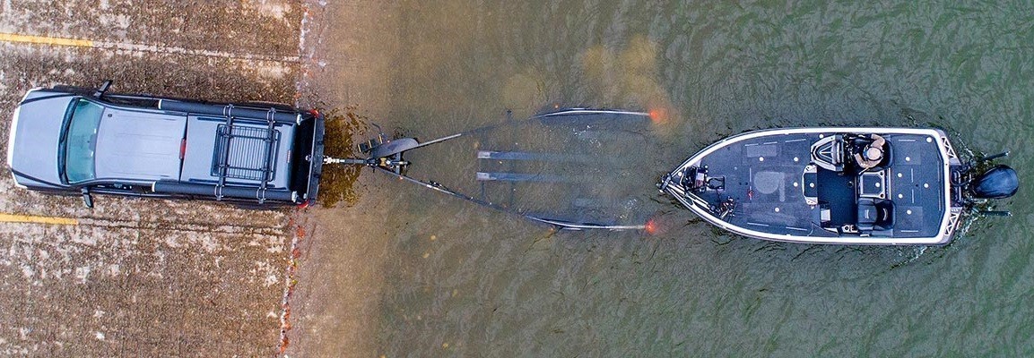
Комбинируйте основные рыболовные продукты Lowrance на вашей лодке, чтобы создать единую систему для эффективной рыбалки. Перемещайтесь, следите за своим местоположением, настраивайте режимы сонара, следуйте по маршруту, бросайте якорь или включайте музыку. С единой рыболовной системой Lowrance у вас есть полный обзор и контроль в любой ситуации на воде.
Перед началом монтажа обязательно отключите электропитание. Если во время установки включено питание, это может привести к пожару, поражению электрическим током или другим серьезным травмам. Убедитесь, что напряжение источника питания совместимо с устройством. Положительный провод питания всегда должен быть подключен к (+) постоянному току с помощью плавкого предохранителя или автоматического выключателя (ближайший доступный по номиналу плавкого …
Создание картографии в режиме реального времени Genesis Live позволяется создавать карты в режиме реального времени для максимальной ситуационной осведомленности. Используя цифровые значения глубины для создания наложения контуров на карту, можно сделать вывод, что Genesis Live невероятно прост в использовании. Вы имеете большие возможности по настройке отображения картографии. Настройте прозрачность изобат, их плотность, цветовую палитру затенения …
Сколько устройств можно связать в сети Wi-Fi? Два устройства Elite Ti2