- Manuals
- Brands
- Linhai Manuals
- Utility Vehicle
- T-Boss 550
- Service manual
-
Contents
-
Table of Contents
-
Troubleshooting
-
Bookmarks
Quick Links
SERVICE MANUAL
T-Boss 550
Related Manuals for Linhai T-Boss 550
Summary of Contents for Linhai T-Boss 550
-
Page 1
SERVICE MANUAL T-Boss 550… -
Page 2
NOTICE This manual was produced by the Linhai Group primarily for use by Linhai dealers and their qualified mechanics. It is not possible to include all the knowledge of a mechanic in one manual, so it is assumed that anyone who uses this book to perform maintenance and repairs on Linhai vehicle has a basic understanding of the mechanical ideas and the procedures of vehicle repair. -
Page 3
CONTENTS CHAPTER1 ……………………………………………………….General Information CHAPTER2 ………………………………………….……………………Maintenance CHAPTER3…………………………………….……….….…………………….Engine CHAPTER4…………………………………………..…………………………Chassis CHAPTER5………………………………………………….……………….Final Drive CHAPTER6………………………………………………………………………Brakes CHAPTER7………………………………………………….….……………..Electrical… -
Page 4
Never run an engine in an enclosed area. Carbon monoxide exhaust gas is poisonous and can cause severe injury or death. Always start engines outdoors. Gasoline is extremely flammable and explosive under certain conditions. Battery electrolyte is poisonous. It contains sulfuric acid. Serious burns can result from contact with skin, eyes or clothing. -
Page 5
CHAPTER 1 GENERALINFORMATION T-Boss550 SERVICE MANUAL 20.0 CHAPTER 1 GENERAL INFORMATION The parts of different types/ variants/ versions maybe un-interchangeable, even some parts have almost same appearance. Always refer to Parts Manual of each UTV model for spare parts information and service. 1.1 IMPORTANT INFORMATION 1.2 V.I.N AND ENG INE SERIAL NUMB ER 1.3 VEHICLE DIMENSIONS… -
Page 6
CHAPTER 1 GENERALINFORMATION T-Boss550 SERVICE MANUAL 20.0 1.1 IMPORTANT INFORMATION PREPARATION FOR REMOVAL PROCEDURES 1. Remove all dirt, mud, dust and foreign material before removal and disassembly. 2. Use proper tools and cleaning equipment. 3. When disassembling the machine, always keep mated parts together. This includes gears, cylinders, pistons and other parts that have been ”mated ”through normal wear. -
Page 7
CHAPTER 1 GENERALINFORMATION T-Boss550 SERVICE MANUAL 20.0 CIRCLIPS 1. Check circlips carefully before reassembly. Always replace piston pin clips after one use. Replace distorted circlips. When installing a circlip ① , make sure that the sharp-edged corner ② is positioned opposite the thrust ③ it receives. -
Page 8
CHAPTER 1 GENERALINFORMATION T-Boss550 SERVICE MANUAL 20.0 Never run an engine in an enclosed area. Carbon monoxide exhaust gas is poisonous and can cause severe injury or death. Always start engines outdoors. Gasoline is extremely flammable and explosive under certain conditions. Battery electrolyte is poisonous. -
Page 9
CHAPTER 1 GENERALINFORMATION T-Boss550 SERVICE MANUAL 20.0 V.I.N AND ENGINE SERIAL NUMBER The vehicle identification number ○ stamped into the rear right of the frame tube. The engine serial number ② is stamped into left side of engine crankcase. CHAPTER 1 GENERAL PAGE. -
Page 10
CHAPTER 1 GENERALINFORMATION T-Boss550 SERVICE MANUAL 20.0 VEHICLE DIMENSIONS CHAPTER 1 GENERAL PAGE. 1-… -
Page 11
CHAPTER 1 GENERALINFORMATION T-Boss550 SERVICE MANUAL 20.0 NOTES CHAPTER 1 GENERAL PAGE. 1-… -
Page 12
CHAPTER 2 MAINTENANCE T-Boss550 SERVICE MANUAL 20.0 CHAPTER 2 MAINTENANCE The parts of different types/ variants/ versions maybe un-interchangeable, even some parts have almost same appearance. Always refer to Parts Manual of each UTV model for spare parts information and service. 2.1 PERIODIC MAI NTE NANCE 2.2 THROTTLE PEDAL INSPECTION 2.3 CHOKE ADJUS TMETN… -
Page 13
CHAPTER 2 MAINTENANCE T-Boss550 SERVICE MANUAL 20.0 2.1 PERIODIC MAINTENANCE GENARAL CAUTION Mark on the following chart DL :Due to the nature of the adjustments marked with a DL on the following chart, it is recommended that service be performed by an authorized dealer. ▲:… -
Page 14
CHAPTER 2 MAINTENANCE T-Boss550 SERVICE MANUAL 20.0 Headlamp Inspection Daily apply dielectric grease to connector when replaced Tail lamp inspection Daily apply dielectric grease to socket when replaced ▲ Air Filter-Main Element Weekly Replace if necessary ▲ Transmission Oil Level Monthly change annually Battery Terminals… -
Page 15
CHAPTER 2 MAINTENANCE T-Boss550 SERVICE MANUAL 20.0 ▲ Steering 6 months T if necessary ▲ Front Suspension 6 months T if necessary ▲ Rear Suspension 6 months T if necessary Spark Plug 12 months R if necessary Ignition Timing 12 months Adjust as needed Check for leaks at tank, cap, lines, fuel Fuel System… -
Page 16
CHAPTER 2 MAINTENANCE T-Boss550 SERVICE MANUAL 20.0 are replaced Headlight Aim As Required Adjust if necessary ▲ I, (for damage, wear, and play) Ball joint (A arm- strut) monthly R. Replace if necessary LUBRICANT AND FLUID Item Lube Rec Method Frequency SAE15W/40 Add to proper level on… -
Page 17
CHAPTER 2 MAINTENANCE T-Boss550 SERVICE MANUAL 20.0 Grease, inspect 12.Throttle Monthly Grease M and replace it if Cable hours necessary Accelerator Monthly pedal brake Grease Grease, inspect hours pedal LUBRICATION RECOMMENDATIONS NOTE: 1.More often under severe use, such as wet or dusty conditions. 2.Grease: Light weight lithium-soap grease. -
Page 18
CHAPTER 2 MAINTENANCE T-Boss550 SERVICE MANUAL 20.0 2.2 THROTTLE PEDAL INSPECTION THROTTLE FREEPLAY If the throttle pedal has excessive play due to cable stretch or cable misadjustment, it will cause a delay in throttle speed. Also, the throttle may not open fully. If the throttle pedal has no play, the throttle may be hard to control, and the idle speed may be erratic. -
Page 19
CHAPTER 2 MAINTENANCE T-Boss550 SERVICE MANUAL 20.0 2.4 FUEL SYSTEM Always stop the engine and refuel outdoors or in a well venltilated area. Do not smoke or allow open flames or sparks in or near the area where refueling is performed or where gasoline is stored. -
Page 20
CHAPTER 2 MAINTENANCE T-Boss550 SERVICE MANUAL 20.0 upwards. 2.5 TOE ALIGNMENT METHOD: STRAIGHTEDGE OR STRING Be sure the steering wheel in a straight ahead position. NOTE: String should just touch side surface of rear tire on each side of the UTV. Measure from string to rim at front and rear of rim. -
Page 21
CHAPTER 2 MAINTENANCE T-Boss550 SERVICE MANUAL 20.0 BRAKE PAD INSPECTION Pads should be changed when friction material is worn to 3/64″ (1mm). HOSE/FITTING INSPECTION Check braking system hoses and fittings for cracks, deterioration, abrasion, and leaks. Tighten any loose fittings and replace any worn or damaged parts. ADJUSTING THE BRAKE PEDAL Check the brake pedal free play. -
Page 22
CHAPTER 2 MAINTENANCE T-Boss550 SERVICE MANUAL 20.0 dragging. 6. Turn the adjustor (the one on the lever) and apply the lever. While adjusting, it is important you apply the lever back and forth for operation, free play and the locking of the parking position. 7. -
Page 23
CHAPTER 2 MAINTENANCE T-Boss550 SERVICE MANUAL 20.0 Always adjust both shock absorber spring preload to the same setting. Uneven adjustment can cause poor handling and loss of stability. Turn the adjuster ○ to increase or decrease the spring preload. Standard position: 3 Minimum (Soft) position: 1 Maximum (Hard) position: 5 2.8 WHEELS… -
Page 24
CHAPTER 2 MAINTENANCE T-Boss550 SERVICE MANUAL 20.0 2.9 TIRE PRESSURE TIRE INSPECTION CAUTION: Maintain proper tire pressure. Refer to the warning tire pressure decal applied to the Tire Pressure Inspection vehicle. Improper tire inflation affect Front Rear maneuverability. see detail on the see detail on the … -
Page 25
CHAPTER 2 MAINTENANCE T-Boss550 SERVICE MANUAL 20.0 NOTES CHAPTER 2 MAINTENANCE PAGE. 2- 14… -
Page 26
CHAPTER 3 ENGINE T-Boss550 SERVICE MANUAL20.0 CHAPTER 3 ENGINE 500 cc 3.1 Removal and Installation of Engine 3.2 Engine Overhaul Information Checks & Adjustment Engine Removal, Inspection & Installation FUEL INJECTION SYSTEM Cooling and Lubrication System Troubleshooting CHAPTER 3 ENGINE PAGE. -
Page 27
CHAPTER 3 ENGINE T-Boss550 SERVICE MANUAL20.0 3.1. Removal and Installation of Engine Overhaul Info…..……………………………..3.1.1 Engine Removal and Installation……………3.1.2 3.1.1 Overhaul info Operation cautions ●Securely support the UTV with bracket when removing or installing engine. Take care not to damage frame, engine body, bolts and cables. ●Wrap the frame to avoid any possible damage when removing or installing the engine. -
Page 28
CHAPTER 3 ENGINE T-Boss550 SERVICE MANUAL20.0 ●Engine Removal Remove: —Plastic —Cushion Support Component —Air Filter —Throttle Body —Clamp —Water Inlet Hose Remove cable shifter Remove bolt Remove shifting anchor plate Remove connector of water temperature transducer Remove clamp Remove water outlet hose Remove connectors of magneto, enriching device lead, pickup, water temperature transducer, gear sensor as illustrated on the right. -
Page 29
CHAPTER 3 ENGINE T-Boss550 SERVICE MANUAL20.0 Remove spark plug cap from cylinder. Remove protection sleeve of starter relay. Remove Nut. Disconnect positive wire of starter relay. Remove Bolt. Remove negative wire of starter relay. Remove the Bolt and Nut of upper engine hanger. CHAPTER 3 ENGINE PAGE. -
Page 30
CHAPTER 3 ENGINE T-Boss550 SERVICE MANUAL20.0 Remove 2 Bolts and Nuts of lower engine hanger Remove 4 Bolts of lower engine hanger. Remove 4 Bolts of front steering kunckle connected with the engine Remove 4 Bolts of rear steering kunckle connected with the engine CHAPTER 3 ENGINE PAGE. -
Page 31
CHAPTER 3 ENGINE T-Boss550 SERVICE MANUAL20.0 3.1.2 Engine Installation Put engine onto the frame,install the two lower mounting bolts and nuts. Then install the upper and lower engine hangers. Tightening torque: Engine upper hanger bolt:50~60N•m Engine lower hanger bolt:50~60N•m Install: —Water outlet and inlet hoses to engine with proper clamps. -
Page 32
CHAPTER 3 ENGINE T-Boss550 SERVICE MANUAL20.0 3.2.Engine Overhaul Information Conversion Table ………………………………………………………………… ……… 3.2.1 General Precautions …………………………………………..………………… ………. 3.2.2 Fuel, Oil and Coolant ……………………………………………………………… …… 3.2.3 Brake-in Procedures …………………………………………………………………… …3.2.4 Engine Exterior and Engine No ………………………………………………………… 3.2.5 Engine Specification …………………………………………………………..……………3.2.6 Overhaul Data………………………………………………………………………………. -
Page 33
CHAPTER 3 ENGINE T-Boss550 SERVICE MANUAL20.0 3.2.1 COVNERSION TABLE Item Conversion Press 1mmHg=133.322Pa=0.133322KPa 1kgf/cm =98.0665KPa 1KPa=1000Pa Torque 1kgf.m=9.80665N.m Volume 1ml=1cm =1cc 1l=1000 cm Force 1kgf=9.80665N Warning/Caution/Note Please read this manual and follow is instructions carefully. To emphasize special information, the symbol and the words WARNING,CAUTION and NOTE have special meanings. -
Page 34
Do not dispose used oil, coolant or defective parts optionally for environmental purpose. CAUTION: Use genuine LINHAI parts or their equivalent. Place and store the disassembled parts separately in order for correct assemble. Use special tools according to service manual. -
Page 35
CHAPTER 3 ENGINE T-Boss550 SERVICE MANUAL20.0 Use a premium quality 4-stroke motor oil to ensure longer service life of your vehicle. Use only oils that meet API service classifications SG and that have a viscosity rating of SAE15W/40. If oil with a rating of SAE 15W/40 is not available, select an alternative according to the chart. -
Page 36
CHAPTER 3 ENGINE T-Boss550 SERVICE MANUAL20.0 3.2.5 Engine Exterior and Engine No CHAPTER 3 ENGINE PAGE. 3- 11… -
Page 37
CHAPTER 3 ENGINE T-Boss550 SERVICE MANUAL20.0 3.2.6 Engine Specification REF. ITEM Type/SPECIFICATION Single Cylinder, 4-Storke, Liquid-cooled, Type 4 Valve, SOHC Bore and stroke 87.5mm×82.0mm Displacement 493ml Compression ratio 10.2: 1 Lowest continuous idle speed with load 1400r/min±100r/min Starting type Electrical starting Ignition / ECU Magneto ignition/BTDC10°… -
Page 38
CHAPTER 3 ENGINE T-Boss550 SERVICE MANUAL20.0 3.2.7 Overhaul Data Item Standard Service Limit Remark Valve Head Diameter 30.6 ———— 27.0 0.05-0.10 Valve Clearance ———— 0.010-0.037 Clearance Between Valve 0.010-0.037 ———— Guide and Valve Stem 0.030-0.057 Inner Diameter of Valve IN & EX 5.000-5.012 ————- Guide… -
Page 39
CHAPTER 3 ENGINE T-Boss550 SERVICE MANUAL20.0 Cylinder + Piston + Piston Ring + Connecting Rod Item Standard Service Limit Remark Cylinder Pressure 1000KPa ———— Cylinder-Piston Clearance 0.030-0.051 0.15 Piston Skirt Diameter 87.460-87.480 87.380 (10mm form skirt end) Inner Diameter of Cylinder 87.500-87.522 ———— Cylinder Joint Face Distortion… -
Page 40
CHAPTER 3 ENGINE T-Boss550 SERVICE MANUAL20.0 Clutch + Transfer Item Standard Service Limit Remark Clutch Plate Inner diameter 140.00-140.15 140.50 Clutch Engagement Speed 1800-2400r/min ——— Clutch Lock Speed 3300-3900r/min ——— Drive Belt Width 35.2 33.5 Free length of Secondary Sheave Spring Shift Fork to Groove 0.10-0.40 0.50… -
Page 41
CHAPTER 3 ENGINE T-Boss550 SERVICE MANUAL20.0 Electrical System Item Standard Remark Spark Plug Type NGK;DPR7EA-9 0.8-0.9 Spark Character >8mm 0.1Ω-0.5Ω Ignition coil Primary Resistance 12Ω-22Ω Secondary 150Ω-300Ω Magneto Coil Pick-up Resistance Magneto Voltage (Without load) >100V(AC),5000r/min Max. Magneto Output Power 300W, 5000r/min Regulated Voltage 13.5V-15.0V, 5000r/min… -
Page 42
CHAPTER 3 ENGINE T-Boss550 SERVICE MANUAL20.0 3.2.8 Tightening Torques Item Quantities Thread Size (mm) Tightening Torque Remark (N.m) Reverse Gear Sensor M10×1.25 Spark Plug M12×1.25 Water-temperature M12×1.5 Apply Thread Locker Sensor Adjusting Nut, Valve Clearance Nut, Primary Sheave M20×1.5 Nut, Secondary M20×1.5 Sheave… -
Page 43
CHAPTER 3 ENGINE T-Boss550 SERVICE MANUAL20.0 Tightening Torques Item Quantiti Thread Size Tightening Torque Remark (mm) (N.m) Bolt, Crankcase Bolt, Driven Sector Gear Bolt, Oil Filter M20×1.5 Bolt, Oil Starter Motor Bolt, Cylinder Head Bolt, Cylinder Head Bolt, Cylinder (Upper & Lower) Bolt, Cylinder Head Cover… -
Page 44
CHAPTER 3 ENGINE T-Boss550 SERVICE MANUAL20.0 3.2.9 Maintenance Tools Measurement Tools Description Specification Purpose Vernier Caliper 0-150mm For measuring the length and thickness Micrometer 0-25mm For measuring outer diameters of rocker arm, valve stem and camshaft Micrometer 25-50mm For measuring the max. lift of camshaft Micrometer 75-100mm For measuring piston skirt… -
Page 45
CHAPTER 3 ENGINE T-Boss550 SERVICE MANUAL20.0 Special Tools Description Specifications Purpose Spark Plug Wrench Removal and installation of spark plug Clutch Holder For removing/installing clutch carrier nuts Oil Filter Wrench Removal and installation of oil filter cartridge Piston Pin Puller For removal of piston pin Flywheel Puller For removal of magneto rotor… -
Page 46
CHAPTER 3 ENGINE T-Boss550 SERVICE MANUAL20.0 3.2.10Materials for Operation and Fixing Materials for engine operation engine oil, grease and coolant. Fixing materials include sealant, thread locker, etc. Description Type Application Area Remark capacity 10W-50 SN Cylinder bore 1900ml Crankcase (for changing oil) Lubricating Refer to Engine Lubrication 2000ml… -
Page 47
CHAPTER 3 ENGINE T-Boss550 SERVICE MANUAL20.0 3.3. Checks & Adjustment Periodic Maintenance table ……………………………………………………….3.3.1 Procedures of Maintenance and Adjustment…………….……………………..3.3.2 Valve Clearance…………………………………………………………… 3.3.2.1 Engine Idle Speed…………………………………………….…….…….. 3.3.2.2 Spark Plug…………………………………………………………………. 3.3.2.3 Filter…………………………………………………………………………..3.3.2.4 Fuel Hose…………………………………………………………………….3.3.2.5 Drive Belt……………………………………………………………………. 3.3.2.6 Inspection of Lubrication System………………………………………..…….. 3.3.3 Inspection of Cooling System………………………………………………….. -
Page 48
CHAPTER 3 ENGINE T-Boss550 SERVICE MANUAL20.0 3.3.1 Periodic Maintenance Table The table below lists the recommended intervals for all the required periodic maintenance work necessary to keep the vehicle at its best performance and economy. Maintenance intervals are expressed in terms of kilometer, miles and hours, whichever occurs first. -
Page 49
CHAPTER 3 ENGINE T-Boss550 SERVICE MANUAL20.0 3.3.2 Procedures of Maintenance & Adjustment This section describes the maintenance procedures for each item mentioned in the Periodic Maintenance Chart. 3.3.2.1 VALVE CLEARANCE Inspect initially at 20-hour break-in and every 40 hours or every 1000km thereafter. Inspect the clearance after removing cylinder head. -
Page 50
CHAPTER 3 ENGINE T-Boss550 SERVICE MANUAL20.0 Take out the feeler gauge, measure the clearance. If the clearance is incorrect, repeat the above steps until the proper clearance is obtained. Locknut: 10 N•m Caution: Securely tighten the locknut after completing adjustment Install: 2 valve adjusting cover;… -
Page 51
CHAPTER 3 ENGINE T-Boss550 SERVICE MANUAL20.0 In case of carbon deposit, clean with a proper tool. SPARK PLUG GAP Measure the spark plug gap with a feeler gauge. Out of specification: → Adjust Spark plug gap: 0.8-0.9mm Caution: Check the thread size and reach when replacing the spark plug. -
Page 52
CHAPTER 3 ENGINE T-Boss550 SERVICE MANUAL20.0 A—Non-flammable cleaning solvent B—Engine oil SAE#30 or SAE10W/40. Warning: Never use with gasoline or low flash point solvents to clean the filter element Inspect the filter element for tears. torn element must be replaced. Note: If driving under dusty conditions, clean the air filter element more frequently. -
Page 53
CHAPTER 3 ENGINE T-Boss550 SERVICE MANUAL20.0 Inspection: Inspect drive belt for wear and damage. If any cracks or damages are found, replace drive belt with a new one. Inspect drive belt for width, if width is out of service limit, replace drive belt with a new one. -
Page 54
CHAPTER 3 ENGINE T-Boss550 SERVICE MANUAL20.0 3.3.3Inspection of Lubrication System Replace engine oil and oil filter initially at 20 hours or 200km and every 80 hours or 2000km thereafter. Check Engine Oil Level Keep the engine in a plan position. Remove oil dip rod 1 Clean oil dip rod, insert oil dip rod but do not tighten Take out oil dip rod and check if oil is between upper… -
Page 55
CHAPTER 3 ENGINE T-Boss550 SERVICE MANUAL20.0 Install oil dip rod, start the engine and allow it to run for several minutes at idling speed. Turn off the engine and wait for about 3 minutes, and then check the oil level on the dipstick. Caution: The engine oil should be changed when the engine is warm. -
Page 56
CHAPTER 3 ENGINE T-Boss550 SERVICE MANUAL20.0 3.3.4 Inspection of Cooling System Check initially at 40 hours or 1000km, replace coolant every 2 years. Check radiator, reservoir tank and water hoses. Leakage or Damage: → Replace Check coolant level by observing the upper and the lower limit on the reservoir tank. -
Page 57
CHAPTER 3 ENGINE T-Boss550 SERVICE MANUAL20.0 Fill coolant into the reservoir tank till between upper and lower limit. Install reservoir tank cap. Warning: Never mix with other brand Inspection of Radiator Hose Perform inspection every 40 hours Check radiator hose and clamp. Leakage or Damage: →Replace 3.3.5 Inspection of cylinder pressure Check cylinder pressure is necessary. -
Page 58
CHAPTER 3 ENGINE T-Boss550 SERVICE MANUAL20.0 3.3.6 Inspection of Oil Pressure Oil Pressure: 130~170kpa at 3000r/min Lower or higher oil pressure may be caused by: Ⅰ Oil pressure is too low Clogged oil filter; Leakage from oil passage; Damaged O-ring; Oil pump failure;… -
Page 59
CHAPTER 3 ENGINE T-Boss550 SERVICE MANUAL20.0 3.3.7 Inspection of Clutch Engagement and Lock-up Engine is equipped with a centrifugal type automatic clutch. Before checking the initial engagement and clutch lock-up two inspection checks must be performed to thoroughly check the operation of the drive train. I Initial Engagement Inspection Connect tachometer to ignition coil Start engine… -
Page 60
CHAPTER 3 ENGINE T-Boss550 SERVICE MANUAL20.0 Ⅰ 3.4. Engine Removal, Inspection & Installation Engine Removal Δ Preparation before engine removal Prepare a proper tray used for load of components Prepare necessary removal and assembly tools Drain up engine oil Drain up coolant △… -
Page 61
CHAPTER 3 ENGINE T-Boss550 SERVICE MANUAL20.0 Cylinder Head Cover Remove valve adjusting cover Remove12 bolts of cylinder head cover Remove cylinder head cover Timing Chain Tensioner Remove screw plug①, insert a flat screwdriver into slot of timing chain tensioner adjuster , turn it clockwise to lock tensioner spring;… -
Page 62
CHAPTER 3 ENGINE T-Boss550 SERVICE MANUAL20.0 Remove C-ring① Remove timing sprocket from camshaft, remove camshaft Note: Take care not to drop spacer, bolt, bolt lock and C-ring into crankcase. Remove tensioner plate Cylinder Head Remove cylinder head bolt Remove cylinder head bolts diagonally; Remove cylinder head Note: Take care not to drop dowel pin into crankcase… -
Page 63
CHAPTER 3 ENGINE T-Boss550 SERVICE MANUAL20.0 Remove cylinder bolt Remove cylinder Note:Take care not to drop dowel pin into crankcase Remove dowel pin and cylinder gasket Note:When performing above removal process, be sure to hook up timing chain to prevent it from falling into crankcase Piston Remove piston pin circlip①… -
Page 64
CHAPTER 3 ENGINE T-Boss550 SERVICE MANUAL20.0 Oil Filter emove oil filter with special tools Tool: Oil filter Remover Sector Gear Remove bolt of sector gear housing cover Remove wire clip and sector gear housing cover Remove dowel pin and gasket Remove drive sector gear 1 Remove bolt 2 of driven sector gear Remove washer3 and driven sector 4… -
Page 65
CHAPTER 3 ENGINE T-Boss550 SERVICE MANUAL20.0 Water Pump Screw out bolt of water pump Remove water pump Remove left crankcase cover 1. Remove nut. Install special tool to rotor thread; Remove rotor and woodruff key Tool: Rotor Remover CHAPTER 3 ENGINE PAGE. -
Page 66
CHAPTER 3 ENGINE T-Boss550 SERVICE MANUAL20.0 Starting Motor Gear Remove driven gear ① and needle bearing Remove spacer ② · Remove dual gear and shaft ③ · Remove idle gear and shaft ④ Oil Pump Sprocket and Chain Remove drive sprocket nut ⑤ Remove C-ring ⑥… -
Page 67
CHAPTER 3 ENGINE T-Boss550 SERVICE MANUAL20.0 Δ Engine Right Side CVT Cover Remove bolt of CVT cover Remove CVT cover Remove gasket and dowel pin CVT(Continuously Variable Transmission) Remove primary sheave nut Remove primary sliding sheave Remove secondary sheave nut Remove secondary sheave Remove drive belt Remove primary fixed sheave ①… -
Page 68
CHAPTER 3 ENGINE T-Boss550 SERVICE MANUAL20.0 CVT Case Remove bolt 1 of CVT case Remove bolt 2 of CVT case Remove outer clutch face and CVT case Remove dowel pin, front and rear gasket Clutch Remove one-way clutch Remove clutch shoe fixing nut Remove clutch shoe. -
Page 69
CHAPTER 3 ENGINE T-Boss550 SERVICE MANUAL20.0 Engine Center Gear position bolt Remove gear position bolt 1 Remove spring and steel ball Right Crankcase Remove left crankcase bolts Remove right crankcase bolts Separate right crankcase with special tool Caution The Crankcase separator plate should be parallel with the end face of crankcase Crankshaft should remain in the left… -
Page 70
CHAPTER 3 ENGINE T-Boss550 SERVICE MANUAL20.0 Remove Oil seal①, Bearing limit nut② Remove Bearing③, Front Output Shaft ④ Shift Cam, Fork/Shaft Remove Shift Cam⑤, Fork /Shaft⑥ Drive Bevel Gear Remove left crankcase from driven bevel gear Drive Shaft, Drive Shaft Remove drive shaft⑦… -
Page 71
CHAPTER 3 ENGINE T-Boss550 SERVICE MANUAL20.0 Crankshaft Separate crankshaft from left crankcase with special tool Tool: Crankshaft Separator Oil bump, Relief Valve Remove oil bump and relief valve CHAPTER 3 ENGINE PAGE. 3- 46… -
Page 72
CHAPTER 3 ENGINE T-Boss550 SERVICE MANUAL20.0 Engine Components Inspection Cylinder Head Cover Disassembly Caution: Each removed part should be identified to its location, and the pars should be laid out in groups designated as “Exhaust”, “Intake”, so that each will be restored to the original location during assembly. -
Page 73
CHAPTER 3 ENGINE T-Boss550 SERVICE MANUAL20.0 Rocker Arm When checking the rocker arm, check the inner diameter of the valve rocker arm and wear of the camshaft contact surface. Rocker Arm I.D. : .000~12.018mm Tool: Dial Calipers Assembly Note: Intake rocker arm shaft A has oil holes. Apply engine oil to rocker arms and shafts;… -
Page 74
CHAPTER 3 ENGINE T-Boss550 SERVICE MANUAL20.0 Remove thermostat Compress the valve spring and remove valve cotter with tweezers. Tools: Valve Spring Compressor Tweezers Remove valve spring upper seat and valve spring Remove valve from the other side. Remove valve stem seal ring and valve lower seat. CHAPTER 3 ENGINE PAGE. -
Page 75
CHAPTER 3 ENGINE T-Boss550 SERVICE MANUAL20.0 Cylinder Head Distortion Clean off carbon deposit from combustion chamber; Check the gasket surface of the cylinder head for distortion with a straightedge and thickness gauge. Take clearance readings from several places. If any clearance reading is out of the service limit, replace with a new cylinder head. -
Page 76
CHAPTER 3 ENGINE T-Boss550 SERVICE MANUAL20.0 Valve Stem O.D Measure valve stem O.D with a micrometer Service Limit IN: 4.975-4.990mm EX: 4.955-4.970mm Tool: Micrometer (0-25mm) Valve Stem Run-out Support valve stem with V block as illustrated on the right. Check the run-out with a dial gauge. Service Limit: 0.05mm Tool: Magnetism Stand Dial Gauge (1/100) -
Page 77
CHAPTER 3 ENGINE T-Boss550 SERVICE MANUAL20.0 Valve Spring Valve Spring keeps valve and valve seat tight. Weakened spring results in reduced engine power output and chattering noise from valve mechanism. Measure the spring free length. Spring free length out of range: →Replace Service Limit: 38.8mm Tool: Vernier Caliper. -
Page 78
CHAPTER 3 ENGINE T-Boss550 SERVICE MANUAL20.0 Install valve spring with small-pitch end “b” facing cylinder head. Big-pitch end “a” is marked. Put on the valve spring retainer. Use the valve spring compressor to press down the spring. Fit the two cotter halves to the stem end and release compressor to allow the cotter ①… -
Page 79
CHAPTER 3 ENGINE T-Boss550 SERVICE MANUAL20.0 Install thermostat Install thermostat cover Install water temperature sensor, apply thread locker to the thread part, tighten it to the specified torque. Water temperature sensor Tightening torque: 10 N· m Install intake pipe, apply lubricant to 0-ring. Camshaft Check camshaft for wear and run-out of cams and journals if the engines produces abnormal noise or… -
Page 80
CHAPTER 3 ENGINE T-Boss550 SERVICE MANUAL20.0 Automatic Decompression Move the automatic decompression weight with hand and check if it is operating smoothly. If it is not working smoothly, replace with a new camshaft/automatic decompression assembly. Cam Wear Worn cams can often cause mistimed valve operation resulting in reduced power output. -
Page 81
CHAPTER 3 ENGINE T-Boss550 SERVICE MANUAL20.0 Camshaft Journal O.D. Measure camshaft journal O.D. with a micrometer. If the O.D. is out of range, replace camshaft with a new one. Camshaft journal O.D. service limit: Sprocket end: 22.959 mm—21.980mm Other end: 17.466mm—17.484mm Tool: micrometer (0-25mm) Camshaft Run-out… -
Page 82
CHAPTER 3 ENGINE T-Boss550 SERVICE MANUAL20.0 Chain Tensioner Inspection Check tensioner for any damage or poor function. Damage, poor function: →Replace Insert screw driver into the slotted end of adjusting screw, turn it clockwise to loosen the tension and release the screwdriver. Check the push rod movement. -
Page 83
CHAPTER 3 ENGINE T-Boss550 SERVICE MANUAL20.0 Piston Piston Diameter Use a micrometer to measure the diameter at the point 10mm above the piston end, as illustrated on the right. If the measurement is less that the limit, replace the piston Standard: 87.460-87.480mm Limit: 87.380mm Tool: Micrometer (75-100mm) -
Page 84
CHAPTER 3 ENGINE T-Boss550 SERVICE MANUAL20.0 Piston Ring Free End Gap and End Gap Before installing piston rings, use vernier caliper to measure the free end gap of each ring, and then fit ring into the cylinder. Use thickness gauge to measure each ring end gap, if any ring has an excess end gap, replace the piston ring. -
Page 85
CHAPTER 3 ENGINE T-Boss550 SERVICE MANUAL20.0 Connecting Rod/Crankshaft Connecting rod small end I.D. Use a dial gauge to measure the I.D. of connecting rod small end. If the measurement exceeds the limit, replace the connecting rod. Connecting rod small end I.D. : 23.040mm Tool: Dial Gauge (18-35mm) Connecting Rod Deflection Check the movement of the small end of the rod and… -
Page 86
CHAPTER 3 ENGINE T-Boss550 SERVICE MANUAL20.0 Clutch Clutch Shoes Check clutch for chipping, scrape, uneven wear or heat discoloration. At the same time check depth of the grooves of clutch shoes. If any of the clutch shoes has no groove, replace the clutch. Note: clutch should be replaced as a set. -
Page 87
CHAPTER 3 ENGINE T-Boss550 SERVICE MANUAL20.0 Primary and Secondary Sheave CHAPTER 3 ENGINE PAGE. 3- 62… -
Page 88
CHAPTER 3 ENGINE T-Boss550 SERVICE MANUAL20.0 Primary Sliding Sheave Disassembly Remove spacer Remove Cam ①and Roller② Roller Check each roller and sliding face for wear and damage. Wear and damage: →Replace Note: rollers should be replaced as a set. Oil Seal Check oil seal lip for wear and damage. -
Page 89
CHAPTER 3 ENGINE T-Boss550 SERVICE MANUAL20.0 Primary Sliding Sheave and Fixed Sheave Check the drive face for any abnormal conditions such as damage or stepped wearing. Damage or wearing: → Replace Install oil seal with special tool. Tool: Bearing install set Assembly Reverse the removal procedure of primary sliding and fixed sheave for installation. -
Page 90
CHAPTER 3 ENGINE T-Boss550 SERVICE MANUAL20.0 Install spacer Secondary Sheave Disassembly Use special tool and holder to hold the secondary sheave. Remove secondary sheave nut with special tool. Caution: Do not remove the ring nut before attaching the clutch spring compressor. Tool: Nut Wrench Sheave Holder Attach special tool to the secondary sliding sheave… -
Page 91
CHAPTER 3 ENGINE T-Boss550 SERVICE MANUAL20.0 Remove spring ① Remove spring seat ②. Remove guide pin and spacer. ③ Remove secondary sliding sheave O-ring and Oil Seal Check the O-ring and oil seal for wear and damage. Wear and Damage: → Replace Remove Oil Seal CHAPTER 3 ENGINE PAGE. -
Page 92
CHAPTER 3 ENGINE T-Boss550 SERVICE MANUAL20.0 Install oil seal with special tool. Tool: Bearing install set Secondary Sheave Spring Use vernier caliper to check the spring free length. If the length is shorter than the service limit, replace with a new one. Service Limit: 145.4mm Secondary Sliding and Fixed Sheave Check drive face for any abnormal condition such… -
Page 93
CHAPTER 3 ENGINE T-Boss550 SERVICE MANUAL20.0 Install guide pin and spacer ① Note: To avoid damage to the oil seal lip during assembly, slide the lip with a 0.1mm steel sheet as guide. Install spring seat. Align hole A with hole B. Install spring and spring plate. -
Page 94
CHAPTER 3 ENGINE T-Boss550 SERVICE MANUAL20.0 Tighten the ring nut with special tool to the specified torque. Ring Nut Tightening Torque: 100N· m Tool: Ring nut wrench Sheave Holder Drive belt Check belt for any greasy substance. Check contact surface of belt for any cracks and damage. -
Page 95
CHAPTER 3 ENGINE T-Boss550 SERVICE MANUAL20.0 Transmission Description Description Qty. MAIN SHAFT. GEARSHIFT DRIVEN GEAR, HIGH RANGE SHIFT CAM DRIVEN GEAR, LOW RANGE RIGHT CRANKCASE SPRING, SHIFT FORK LEFT CRANKCASE RIGHT SHIFT FORK DRIVEN SECTOR GEAR GUIDE BAR SPROCKET, REVERSE GEAR DRIVEN SHAFT CHAIN, REVERSE GEAR SPRING, SHIFT FORK… -
Page 96
CHAPTER 3 ENGINE T-Boss550 SERVICE MANUAL20.0 Inspection Check main shaft gear and sprocket surface for any damage or over wear. Damage or over wear: → Replace Check reverse gear chain for any damage or over wear. Damage or over wear: → Replace Disassemble driven shaft as illustrated. -
Page 97
CHAPTER 3 ENGINE T-Boss550 SERVICE MANUAL20.0 Check the shift fork clearance with a thickness gauge in the groove of its gear. Clearance exceeds the limit: → Replace Shift fork to Groove clearance Standard clearance :0.10-0.30mm Service Limit :0. 50mm Measure shift fork groove width with vernier caliper Standard shift fork groove width: 6.05-6.15mm Measure shift fork thickness with vernier calipers;… -
Page 98
CHAPTER 3 ENGINE T-Boss550 SERVICE MANUAL20.0 Put the guide bar on a flat plate and roll it. In case of any bend, replace with a new one. NOTE:DON NOT attempt to correct a bent guide bar. Check shift fork spring for breakage, damage Broken or damaged: →… -
Page 99
CHAPTER 3 ENGINE T-Boss550 SERVICE MANUAL20.0 When assembling the guide bar, take care not to assemble the two shift forks and springs in the opposite direction. 1. Guide bar 2. Retainer 3. Left shift fork 4. Shift fork Spring (small) 5. -
Page 100
CHAPTER 3 ENGINE T-Boss550 SERVICE MANUAL20.0 Oil strainer Check oil strainer ① and O-ring ② for damage Damaged oil strainer: → Replace Clean the surface of oil strainer with engine oil Relief Valve Check the valve body ① 、valve ② and spring ③O ring④… -
Page 101
CHAPTER 3 ENGINE T-Boss550 SERVICE MANUAL20.0 Front Output Shaft Check bearing 7 for smooth turning and abnormal wear. Check oil seal 5 for damage. Wear or damage: → Replace Apply lubrication oil to bearing 7 and oil seal 5 lip before assembly. -
Page 102
CHAPTER 3 ENGINE T-Boss550 SERVICE MANUAL20.0 Bevel Gear Note: Proper bevel gear engagement depends on that the gear backlash and tooth contact are within the proper range. Bevel Gear Backlash Install drive and driven gears to the crankcase. Wrap a (—) screwdriver ③with a rag ②… -
Page 103
CHAPTER 3 ENGINE T-Boss550 SERVICE MANUAL20.0 Tooth Contact After adjusting the backlash, check the tooth contact according to the following procedures: Remove drive and driven bevel gear shafts from crankcase; Clean and degrease every tooh of drive and driven bevel gear; Coat the driven bevel gear with machinist’s layout dye or paste;… -
Page 104
CHAPTER 3 ENGINE T-Boss550 SERVICE MANUAL20.0 Balancer Shaft Remove the parts as illustrated on the right. Check each part for abnormal wear or damage. Wear or damage: → Replace ① Balancer shaft gear ② Woodruff key ③ Balancer shaft ④ Balancer shaft sprocket ⑤… -
Page 105
CHAPTER 3 ENGINE T-Boss550 SERVICE MANUAL20.0 Check starter clutch roller and holder for abnormal wear or damage. Wear or damage: → Replace Install the starter clutch in the correct direction. Note: When install the starter clutch to the magneto rotor, make sure side “A”… -
Page 106
CHAPTER 3 ENGINE T-Boss550 SERVICE MANUAL20.0 Electric Starter Gear Check the gear surface for scrap or damage. Scrape or Damage: → Replace LEFT CRANKCASE COVER(MODEL2) Check magneto stator coil 2, pickup coil 3 for damage, burn or short circuit, if any , replace with new one; LEFT SIDE COVER Disassembly 1—… -
Page 107
CHAPTER 3 ENGINE T-Boss550 SERVICE MANUAL20.0 CVT Cover Remove screw 5, oil seal limitator 4. Remove oil seal 3 with special tool; Check bearing 2 for free turning. In case of any abnormal, remove with special tool and replace with a new bearing;… -
Page 108
CHAPTER 3 ENGINE T-Boss550 SERVICE MANUAL20.0 Crankcase 1.Right Crankcase 11.Gear Sensor 21.Bearing 2.Bearing 12.Bolt 22.Bearing 3.Seal 13.Left Crankcase 23.Oil Dip Rod 4.Bearing 14.Oil Pipe 1 24.O-ring 5.Bearing 15.Oil Pipe 2 25.Bolt 6.Bearing 16.Link Bolt 26.Speed Sensor 7.Oil Seal 17.Washer 27.O-ring 8.Washer,Reverse Gear Sensor 18.Bearing 28.Washer… -
Page 109
CHAPTER 3 ENGINE T-Boss550 SERVICE MANUAL20.0 Clean and grease the bearings, turn the inner race of bearing and check the play, noise and smooth turning. In case of any abnormal, remove bearing with special tool and replace; Check all the oil seals for over wear or damage. In case of any over wear or damage, remove with special tool and replace with a new oil seal;… -
Page 110
CHAPTER 3 ENGINE T-Boss550 SERVICE MANUAL20.0 Connecting Rod Install connecting rod to left crankcase with special tool; Note: Do not hammer the conrod into crankcase with plastic mallet; Use special tool to avoid affect of conrod precision Tool: Conrod Installer Balancer Shaft Install balancer shaft Caution: Balancer shaft driven gear should be aligned to… -
Page 111
CHAPTER 3 ENGINE T-Boss550 SERVICE MANUAL20.0 Shift Cam, Shift For Install shift can① and shift fork② Check each part for smooth turning Install low range driven gear to counter shaft③ Spray adequate engine oil to each part. Drive Bevel Gear Install drive bevel gear and tighten to the specified torque. -
Page 112
CHAPTER 3 ENGINE T-Boss550 SERVICE MANUAL20.0 Apply sealant ①to the mating face of right crankcase. Note: Apply sealant evenly in an uninterrupted thin line. Install 5 dowel pins② Assemble crankcase and tap slightly with a rubber hammer so that the crankcase is properly fitted. Install bolt and tighten to the specified torque. -
Page 113
CHAPTER 3 ENGINE T-Boss550 SERVICE MANUAL20.0 Install new o-ring⑥ in spacer⑧ Install spacer onto the clutch housing shaft, then install into CVT case Note: align oil nick on spacer with oil hole on the shaft CVT Case Install dowel pin ④, gasket ② and gasket⑤ to the right crankcase. -
Page 114
CHAPTER 3 ENGINE T-Boss550 SERVICE MANUAL20.0 Install secondary sheave; Install primary sliding sheave Tighten primary sheave nut to the specified torque; Primary sheave nut tightening torque: 115 N· m Tighten secondary sheave nut to the specified torque; Secondary sheave tightening torque: 115 N·… -
Page 115
CHAPTER 3 ENGINE T-Boss550 SERVICE MANUAL20.0 Install CVT case cover bolts and tighten diagonally in several steps. Engine Left Oil Pump Sprocket and Chain Install oil pump drive sprocket; Install oil pump driven sprocket; Install oil pump drive chain; Install oil pump sprocket bolt; Install sprocket retainer with a long nose pliers Tool: Long Nose Pliers Dual Gear, Idle Gear… -
Page 116
CHAPTER 3 ENGINE T-Boss550 SERVICE MANUAL20.0 Install starting driven gear; Magneto Rotor Install Magneto Rotor (1) Install Nut Nut tightening torque: 160N•m Install left crankcase cover ( Install end cap (2) CHAPTER 3 ENGINE PAGE. 3- 91… -
Page 117
CHAPTER 3 ENGINE T-Boss550 SERVICE MANUAL20.0 Water Pump Install water pump; Install water pump fixing bolts; Note: Before tightening the bolts, be sure to insert oil pump shaft into groove of water pump shaft. Sector Gear Install the parts as illustrated on the right. 1- sector gear cover and gasket 2-dowel pin 3-drive sector gear… -
Page 118
CHAPTER 3 ENGINE T-Boss550 SERVICE MANUAL20.0 Oil Filter Install oil filter bolt and tighten to the specified torque; Oil filter bolt tightening torque: 36 N· m Apply engine oil to O-ring; Install oil filter, turn it by hand until the filter gasket contacts the mating surface. -
Page 119
CHAPTER 3 ENGINE T-Boss550 SERVICE MANUAL20.0 1st and 2nd rings have letter “R” marked on the side. Be sure to bring the marked side to the top when fitting them to the piston. Position the gaps of the three rings as illustrated on the right. -
Page 120
CHAPTER 3 ENGINE T-Boss550 SERVICE MANUAL20.0 Cylinder Apply engine oil to piston skirt and cylinder wall; Hold each piston ring with proper position, insert piston into the cylinder; Tighten the cylinder base bolts temporarily; Note: When installing the cylinder and cylinder head, pull the cam chain upward, or the chain will be caught between sprocket and crankcase. -
Page 121
CHAPTER 3 ENGINE T-Boss550 SERVICE MANUAL20.0 Install chain tensioner; Camshaft Align mark “A” on magneto rotor with mark “B” on crankcase; Note: while rotating crankshaft, pull the cam chain upward, or the chain will be caught between sprocket and crankcase. Align the mark “A”… -
Page 122
CHAPTER 3 ENGINE T-Boss550 SERVICE MANUAL20.0 Install crankshaft C-ring ① Install lock washer so that it covers the locating pin; Apply thread locker to the bolts before installing, and tighten them to the specified torque; Sprocket bolt tightening torque: 15 N· m Bend up the lock washer to lock the bolts. -
Page 123
CHAPTER 3 ENGINE T-Boss550 SERVICE MANUAL20.0 Gasket Sealant Applying Place Chain Tensioner Insert (—) screwdriver into slotted end of chain tension adjuster, turn it clockwise to lock the tensioner spring; Install the chain tensioner and the new washer (1); Install the bolt (2), tighten it to the specified torque; Chain tensioner bolt tightening torque: 10 N·… -
Page 124
CHAPTER 3 ENGINE T-Boss550 SERVICE MANUAL20.0 Install the new gasket (3); Install chain tensioner screw, tighten it to the specifiedTorque Chain tensioner screw tightening torque: 8 N· m Valve Adjuster Cover Use new rubber gasket and apply grease; Install Valve Inspection Cap Install valve inspection cap bolt;… -
Page 125
CHAPTER 3 ENGINE T-Boss550 SERVICE MANUAL20.0 Water Pipe and Hose Install water hose (5) Install bolt (4) Install water hose (3) Install clamp (1) and (2) CHAPTER 3 ENGINE PAGE. 3- 100… -
Page 126
CHAPTER 3 ENGINE T-Boss550 SERVICE MANUAL20.0 FUEL INJECTION SYSTEM 3.5. 3.5.1 3.5.1.1 Description & Working Principle 3.5.1.2 Appearance 3.5.1.3 Handling – Don’ts & Do’s 3.5.1.4 Installation requirements 3.5.1.5 Power Requirements 3.5.1.6 Temperature Requirements 3.5.1.7 Maintenance service and Repair 3.5.2 INJECTOR 3.5.2.1 Appearance 3.5.2.2 Temperature Requirements : 3.5.2.3 Fuel Contamination… -
Page 127
CHAPTER 3 ENGINE T-Boss550 SERVICE MANUAL20.0 3.5.8 Fuel Pump Module 3.5.8.1 Description and Working Principle 3.5.8.2 Appearance 3.5.8.3 Operating Conditions 3.5.8.4 Service Procedure 3.5.8.5 Fuel Module Removal: 3.5.8.6 Fuel Module Installation: 3.5.8.7 Fuel Pressure Relief Procedure: 3.5.8.8 Fuel Leakage Check Procedure: 3.5.9 Motor Scanner ( for MT05 EMS) 3.5.9.1 Precautions… -
Page 128
CHAPTER 3 ENGINE T-Boss550 SERVICE MANUAL20.0 3.5.1 ECU 3.5.1.1 Description & Working Principle The ECU continuously monitors the operating conditions of the engine through the system sensors. It also provides the necessary computation, adaptability, and output control in order to minimize the tailpipe emissions and fuel consumption, while optimizing vehicle drivability for all operating conditions. -
Page 129
CHAPTER 3 ENGINE T-Boss550 SERVICE MANUAL20.0 3.5.1.5 Power Requirements ● Operating Range: All planned functions are executed in this range. Battery and/or Ignition voltage: 9.0 to 16V DC. However, when the battery voltage is lower than 13.6 volts, the engine’s start speed may be low. -
Page 130
CHAPTER 3 ENGINE T-Boss550 SERVICE MANUAL20.0 tank. 3.5.2.4 Injector Installation Follow these guidelines to prevent damage to the injector and its electrical interface during the replacement or re-installation process. ● Lubrication: Apply a light coating of lubricant to the lower injector seal ring. ISO 10 light mineral oil or equivalent is recommended. -
Page 131
CHAPTER 3 ENGINE T-Boss550 SERVICE MANUAL20.0 3.5.2.5 Replacement Techniques The following procedure outlines standard the Injector removal and replacement. Warning: The injector and all associated hardware may be extremely hot. ● Shut off ignition. ● Disconnect negative battery cable to avoid possible fuel discharge if an accidental attempt is made to start the engine. -
Page 132
CHAPTER 3 ENGINE T-Boss550 SERVICE MANUAL20.0 ● Injector cleaner with the specific ratio of the cleaner and gasoline to be mixed in the Injector cleaning tank. ● Connect the injector-cleaning tank to injector in the vehicle. ● Pressurize the injector-cleaning tank to system pressure. ●… -
Page 133
CHAPTER 3 ENGINE T-Boss550 SERVICE MANUAL20.0 3.5.3.4 Cleaning Procedure If there is cover on the bottom, it may be removed and cleaned using carburetor cleaner (3M make recommended). Once the throttle body cover is removed, spray the throttle-body cleaner inside the shipping air passage, and use the brushes to gently dislodge the dirt, gum and varnish that are present. -
Page 134
CHAPTER 3 ENGINE T-Boss550 SERVICE MANUAL20.0 is the intake manifold air pressure; it provides a voltage varies as the intake air pressure. This Throttle Body Assembly. sensor is installed on the 3.5.5.2 Appearance 3.5.5.3 Operating Environment This device is intended for use in inlet manifold for sensing air temperature and pressure which shall withstand such an under hood environment. -
Page 135
CHAPTER 3 ENGINE T-Boss550 SERVICE MANUAL20.0 3.5.6.4 Fuel Quality Requirements ● Pb≤0.005g/L ● P≤0.0002g/L ● S≤0.04% (weight proportion)x ● MMT≤0.0085g/L ● Si≤4ppm 3.5.7 Ignition Coil 3.5.7.1 Description and Working Principle This coil provides energy to the spark plug in the combustion chamber. The coil itself doesn’t have a driver. -
Page 136
CHAPTER 3 ENGINE T-Boss550 SERVICE MANUAL20.0 DO NOT: Strike any part of the ignition system with a This can lead to physical damage which can cause a tool or other object. system malfunction or failure. Insulating type sprays can create a high resistance DO NOT: Permit paint or other sprayed materials to or open connection. -
Page 137
CHAPTER 3 ENGINE T-Boss550 SERVICE MANUAL20.0 the engine. performance degradation or failure. DO: Connection of the module back plate to vehicle This greatly reduce potential ground loops and acts ground is desirable whenever possible. as a heat transfer source from the module. DO: The ignition system ground wire should be kept as short as possible. -
Page 138
CHAPTER 3 ENGINE T-Boss550 SERVICE MANUAL20.0 specified by the engine manufacturer to keep the misfire(higher required ignition voltage). best fuel economy and proper engine performance: — Too narrow of a gap could affect idle stability. — Use round wire-type gauge for an accurate — A flat gauge can’t accurately measure the spark measure of gap on all used spark plugs. -
Page 139
CHAPTER 3 ENGINE T-Boss550 SERVICE MANUAL20.0 3.5.8.3 Operating Conditions ● Fuel Pump Module needs to be mounted on Fuel Tank Top according to the installation instructions. ● Fuel Pump Module is intended to use with gasoline. However if the fuel contains ethanol, please contact vehicle manufacture to check whether the fuel pump module itself can survive or not. -
Page 140
CHAPTER 3 ENGINE T-Boss550 SERVICE MANUAL20.0 Fuel Module Diagnosis: Step Action Switch on Ignition key. Fuel Pump primes for 3 seconds when the ignition If fuel pump running noise If fuel pump running noise key is ON. can not be heard, go to step can be heard, go to step 4. -
Page 141
CHAPTER 3 ENGINE T-Boss550 SERVICE MANUAL20.0 ● Place the bolts on module cover and tighten the bolts gradually in star pattern sequence to apply equal compression on gasket. It is shown as below: Bolt Tightening Torque: 10 Nm. Fuel module is installed with the M6×10 bolts. Use designated bolts only. -
Page 142
CHAPTER 3 ENGINE T-Boss550 SERVICE MANUAL20.0 ● Never test electrical signals that exceed the limit of specifications. ● Test cannot be performed by the person who is driving the car. ● This unit should be used and stored in the following conditions: Ambient temperature: 0~50℃… -
Page 143
CHAPTER 3 ENGINE T-Boss550 SERVICE MANUAL20.0 Seconds later, the unit will display: 3.5.9.4 Functions Delphi Motor-Scanner can be used to diagnose Delphi Engine Management System with functions: Read DTC, Clear DTC, Data Stream, Status Stream, and Record Data. Operations When the unit is powered up, the screen will display the interface as below. Here, we take diagnostic function for demonstration. -
Page 144
CHAPTER 3 ENGINE T-Boss550 SERVICE MANUAL20.0 Select ‘English’ and press key, it will display information about the diagnostic software version, press to continue, the interface will display as below: Diagnostic Function Here, we take ‘diagnostic function’ for demonstration. Select ‘diagnostic function’ and press , the screen will display an interface to indicate ‘Delphi-3’… -
Page 145
CHAPTER 3 ENGINE T-Boss550 SERVICE MANUAL20.0 , with ‘accessing system’ fleeting on the screen, then, it will display as below: Press Available functions are as follows: ● Read DTC ● Clear DTC ● Data Stream ● Status Stream ● Record Data Press key to select function you needed. -
Page 146
CHAPTER 3 ENGINE T-Boss550 SERVICE MANUAL20.0 2. Clear DTC Select ‘Clear DTC’ and press , it will display as below: 3. Data Stream Select ‘Data Stream’ and press , it will display as below: Press key for page up/down to view more. Press key to exit. -
Page 147
CHAPTER 3 ENGINE T-Boss550 SERVICE MANUAL20.0 3.5.9.5 MT05 ECU Malf Code Malf code Description P0107 MAP Circuit Low Voltage or Open P0108 MAP Circuit High Voltage P0112 IAT Circuit Low Voltage P0113 IAT Circuit High Voltage or Open P0117 Coolant/Oil Temperature Sensor Circuit Low Voltage P0118 Coolant/Oil Temperature Sensor Circuit High Voltage or Open P0122… -
Page 148
CHAPTER 3 ENGINE T-Boss550 SERVICE MANUAL20.0 3.6. Cooling and Lubrication System Engine Coolant………………………………………………………3.6.1 Inspection of Cooling Circuit……………………….………………3.6.2 Inspection and Cleaning of Radiator and Water Hoses…………3.6.3 Inspection of Fan Motor……………………………………….……3.6.4 Inspection of Water Temperature Sensor…………………………3.6.5 Inspection of Thermostat……………………………………………3.6.6 Water Pump……………………………………………………….…3.6.7 Water Pump Removal and Disassembly……………………3.6.7.1 Inspection………………………………………………………3.6.7.2 Water Pump Assembly and Installation………..……………3.6.7.3 Lubrication System Illustration………………………………..……3..6.8… -
Page 149
CHAPTER 3 ENGINE T-Boss550 SERVICE MANUAL20.0 3.6.1 Engine Coolant The coolant used in cooling system is a 100% ethylene glycol antifreeze. Warning ! DO NOT open radiator cap when the engine is still hot. Or you may be injured by scalding fluid or steam;… -
Page 150
CHAPTER 3 ENGINE T-Boss550 SERVICE MANUAL20.0 3.6.3 Inspection and Cleaning of Radiator and Water Hoses Radiator Cap Remove radiator cap① Install radiator cap to cap tester② Slowly increase pressure to 110-140 kPa and check if the cap can hold the pressure for at least 10 seconds. -
Page 151
CHAPTER 3 ENGINE T-Boss550 SERVICE MANUAL20.0 3.6.4 Inspection of Fan Motor Remove fan motor from radiator Turn the vanes and check if they can turn smoothly; Check fan motor: Make sure that the battery applies 12 volts to the motor and the motor will run at full speed while the ammeter shall indicate the ampere not more than 5A. -
Page 152
CHAPTER 3 ENGINE T-Boss550 SERVICE MANUAL20.0 3.6.5 Inspection of Water Temperature Sensor Place a rag under water temperature sensor① and remove it from cylinder head. Check the resistance of water temperature sensor as illustrated on the right. Connect the temperature sensor②… -
Page 153
CHAPTER 3 ENGINE T-Boss550 SERVICE MANUAL20.0 Check thermostat pellet for cracks Test the thermostat in the following steps: Pass a string between thermostat flange as illustrated on the right; Immerse the thermostat in a beaker with water. Make sure that the thermostat is in the suspended position without contact to the vessel. -
Page 154
CHAPTER 3 ENGINE T-Boss550 SERVICE MANUAL20.0 Remove clamps and water hoses Release bolts and remove water pump Remove O-ring Note: Do not reuse the O-ring. Remove the overflow tube Release water pump cover screws, water pump cover and gasket Remove E-ring and impeller Remove seal ring ①and rubber seal②… -
Page 155
CHAPTER 3 ENGINE T-Boss550 SERVICE MANUAL20.0 Remove mechanical seal with special tool Note: The mechanical seal does not need to be removed if there is no abnormal condition. Note: Do not reuse a removed mechanical seal Put a rag on the water pump body Remove oil seal. -
Page 156
CHAPTER 3 ENGINE T-Boss550 SERVICE MANUAL20.0 Oil Seal Check oil seal for damage. Pay special attention to the oil seal lip; In case of damage or leakage, replace the oil seal; Water Pump Body Check the mating mace of water pump body with bearing and mechanical seal. -
Page 157
CHAPTER 3 ENGINE T-Boss550 SERVICE MANUAL20.0 Install mechanical seal with a suitable socket wrench Note: Apply sealant to side “A” of mechanical seal Install bearing with special tool Tool: Bearing Installer Note: The stamped mark on the bearing faces outside. Install seal ring to impeller Clean off the oil and grease from mechanical seal and install it into the impeller. -
Page 158
CHAPTER 3 ENGINE T-Boss550 SERVICE MANUAL20.0 Install E-ring to water pump shaft; Install new gasket to water pump body; Install water pump cover and tighten the bolts and bleed bolt. Water Pump Cover Bolts Tightening Torque: 6N•m Check impeller for smooth turning. Install the new O-ring Note: Use the new O-ring to prevent oil leakage;… -
Page 159
CHAPTER 3 ENGINE T-Boss550 SERVICE MANUAL20.0 Install water pump and tighten the bolts to the specified torque; Water pump bolts tightening torque: 10N•m Note: Set the water pump shaft slot end “B” to oil pump shaft flat side “A”. Connect water hoses Add coolant CHAPTER 3 ENGINE PAGE. -
Page 160
CHAPTER 3 ENGINE T-Boss550 SERVICE MANUAL20.0 3.6.7.8 Lubrication System Illustration CHAPTER 3 ENGINE PAGE. 3- 135… -
Page 161
CHAPTER 3 ENGINE T-Boss550 SERVICE MANUAL20.0 3.7 TROUBLESHOOTING Electrical system 1. Battery GENERAL INFORMATION • Discharged battery • TIP ______________ Faulty battery The following glide for troubleshooting does not 2 Fuse(s) • Blown, damaged a incorrect fuse overall the possible causes of trouble. It should be helpful, however, as a guide to basic trouble- •… -
Page 162
CHAPTER 3 ENGINE T-Boss550 SERVICE MANUAL20.0 • Faulty battery • Broken generator rotor woodruff key 2. Sparkplug • Incorrect spark plug gap POOR MEDIUM-AND-HIGH-SPEED • Incorrect spark plug heat range PERFORMANCE Refer to ‘STARTING FAILURES» on Previous page. • Fouled spark plug •… -
Page 163
CHAPTER 3 ENGINE T-Boss550 SERVICE MANUAL20.0 TIP ____________________________________________________________ Areas A, B, and C above may be extremely difficult to diagnose. The symptoms are quite subtle and difficult to distinguish from normal vehicle operating noise. If there is reason to believe these components are damaged, remove the components and check them. -
Page 164
CHAPTER 3 ENGINE T-Boss550 SERVICE MANUAL20.0 FAULTY CLUTCH OVERHEATING Engine operates but vehicle will not move Engine 1. V-belt 1. Clogged coolant passages • Bent, damaged or worn V-belt 2 Cylinder head and piston • Heavy carbon buildup • Slipping V-belt 3. -
Page 165
CHAPTER 3 ENGINE T-Boss550 SERVICE MANUAL20.0 OVERCOOUNG 6. Frame • Bent frame • Damaged frame Cooling system 1. Thermostat • Thermostat stays open FAULTY LIGHTING OR SIGNAUNG SYSTEM POOR BRAKING PERFORMANCE Headlight does not come on • Worn brake pad •… -
Page 166
CHAPTER 3 ENGINE T-Boss550 SERVICE MANUAL20.0 NOTES CHAPTER 3 ENGINE PAGE. 3- 141… -
Page 167
CHAPTER 4 CHASSIS T-Boss550 SERVICE MANUAL20.0 CHAPTER 4 CHASSIS WARNING The parts of different types/ variants/ versions maybe un-interchangeable, even some parts have almost same appearance. Always refer to Parts Manual of each CUV model for spare parts information and service. 4.1 FRONT A-ARM REPL ACEMENT 4.2 REAR A-ARM REPLACEMENT 4.3 REAR STABILIZER BAR REMOVA L/INSTALLATION… -
Page 168
CHAPTER 4 CHASSIS T-Boss550 SERVICE MANUAL20.0 4.1 FRONT A-ARM REPLACEMENT 1. Carrier Bearing,Front,Lh; 2. Bearing; 3. Circlip 55 4. Nut M12×1.25; 5. Pin 3.2×22; 6. Arm Upper Frt Lh 7. Ball Joint,Upper; 8. Circlip 32; 9. Scr Hxfl,Frt Arm 10. Nut M10; 11. -
Page 169
CHAPTER 4 CHASSIS T-Boss550 SERVICE MANUAL20.0 4.Remove the spindle nut, and washer. Remove the hub assy by sliding it off of the shaft. 5.Remove cotter pin from ball joint stud at wheel end of A- arm and loosen nut until it is flush with end of stud. -
Page 170
CHAPTER 4 CHASSIS T-Boss550 SERVICE MANUAL20.0 4.2 REAR A-ARM REPLACEMENT 1. Carrier Bearing Wheel Rear Lh;2. Grease Fitting M6; 3. Bearing 4. Circlip 63; 5. Shaft Pivot ,Lwr; 6. Scr Hxfl,Rear Arm,Lwr 7. Shaft Pivot ,Upper; 8. Bolt M10X1.25X90; 9.Nut M10 10. -
Page 171
CHAPTER 4 CHASSIS T-Boss550 SERVICE MANUAL20.0 3. Remove the brake caliper. Suspend the brake caliper from the frame with a wire. NOTE: Do not let the brake caliper hand from the brake line or damage may occur. 4. Remove the spindle nut, and washer. Remove the hub assy by sliding it off of the shaft. -
Page 172
CHAPTER 4 CHASSIS T-Boss550 SERVICE MANUAL20.0 8. Examine the A-arm bushing and A-arm shaft. Replace if worn. Discard hardware. 9. Remove the bottom stabilizer bar nut. 10. Loosen two bolts that secure the A –arm bushing to frame by alternating each about 1/3 of the way until the A-arm can be removed. -
Page 173
CHAPTER 4 CHASSIS T-Boss550 SERVICE MANUAL20.0 4.3 REAR STABILIZER BAR REMOVAL/INSTALLATION 1. Elevate and safely support vehicle with weight removed from the rear wheel(s). 2. Remove the rear wheel to gain access to the stabilizer bar, each side. 3. Remove the stabilizer bar nut from the lower A-arm, each side. -
Page 174
CHAPTER 4 CHASSIS T-Boss550 SERVICE MANUAL20.0 4.4 BOX REMOVAL/INSTALLATION Box Removal 1. Disconnect taillight transition line at lower right of the Box from the wiring harness. 2. Lift the box into the dump position. 3. Remove the box shock pin from the frame. 4. -
Page 175
CHAPTER 4 CHASSIS T-Boss550 SERVICE MANUAL20.0 4.5 STEERING ASSEMBLY REMOVAL/INSTALLATION 1. Pin 2.5×25; 2.Nut M10X1.25; 3. Steering Tie-Rod,Rh 4. Steering Tie-Rod,Rh; 5. Steering Motor; 6. Bolt M8X90 7. Bolt M8X90; 8. Bolt M8X20; 9. Nut M8 10. Steering Tie-Rod,Lh; 11. Steering Tie-Rod,Lh; 12. -
Page 176
CHAPTER 4 CHASSIS T-Boss550 SERVICE MANUAL20.0 NOTES CHAPTER 4 CHASSIS PAGE. 4- 10… -
Page 177
CHAPTER 5 FINAL DRIVE T-Boss550 SERVICE MANUAL 20.0 CHAPTER 5 FINAL DRIVE WARNING The parts of different types/ variants/ versions maybe un-interchangeable, even some parts have almost same appearance. Always refer to Parts Manual of each CUV model for spare parts information and service. -
Page 178
CHAPTER 5 FINAL DRIVE T-Boss550 SERVICE MANUAL 20.0 5.1 WH E E L , H U B , AND SPINDLE TORQUE TABLE Item Specification Front heel Nuts 55 Ft.Lbs 75 Nm Rear heel Nuts 55 Ft.Lbs 75 Nm Front Hub Nut on Spindle/ outer CV joint 103 Ft.Lbs 140 Nm Rear Hub Retaining Nut 103Ft.Lbs 140 Nm… -
Page 179
CHAPTER 5 FINAL DRIVE T-Boss550 SERVICE MANUAL 20.0 3. Grasp the top and bottom of the tire. The tire should rotate smoothly without binding or rough spots. 4. Remove wheel nuts and wheel. 5. Remove the two brake caliper mounting bolts. CAUTION: Do not hang the caliper by the brake line. -
Page 180
CHAPTER 5 FINAL DRIVE T-Boss550 SERVICE MANUAL 20.0 5.5 FRONT HUB BEARING REPLACEMENT 1. Remove outer snap ring. 2. From the back side, tap on the outer bearing race with a drift punch in the reliefs as shown. 3. Drive bearing out evenly by tapping on outer race only. -
Page 181
CHAPTER 5 FINAL DRIVE T-Boss550 SERVICE MANUAL 20.0 NOTE: The outer CV joint cannot be disassembled or repaired, if damage or faulty the drive axle assembly must be replace. 1. Drive Axle/Outer CV Joint Assembly. 2. Boot Band “A”. 3. Outer Board Boot. 4. -
Page 182
CHAPTER 5 FINAL DRIVE T-Boss550 SERVICE MANUAL 20.0 chapter. 2. Move each end of the drive shaft in a circular motion (and also a reciprocate for inner one) and check the drive shaft joints for excessive wear or play. 3. This inner CV joint (inboard pivot joint) can be serviced if there is wear or play. -
Page 183
CHAPTER 5 FINAL DRIVE T-Boss550 SERVICE MANUAL 20.0 Discard the boot band, it cannot be reused. 2. Carefully slide the boot (A) onto the drive axle and off the inboard joint. 3. Wipe out all of the molybdenum disulfide grease within the inboard joint cavity. -
Page 184
CHAPTER 5 FINAL DRIVE T-Boss550 SERVICE MANUAL 20.0 9. Inspect the splines on the inner CV joint for wear or damage. 10. Check the stopper ring in the end of the inboard joint. Make sure it seats in the groove correctly, if damage the ring must be replaced. -
Page 185
CHAPTER 5 FINAL DRIVE T-Boss550 SERVICE MANUAL 20.0 clips and tap them with a plastic hammer. Make sure they are locked in place. 5. If the bearing assembly was disassembled, assemble the bearing as follows: a. Position the bearing race and install the race into the bearing case. -
Page 186
CHAPTER 5 FINAL DRIVE T-Boss550 SERVICE MANUAL 20.0 CAUTION: It is critical to avoid undue stress on the rubber boots after the drive axle is installed and the vehicle is run. Don’t twist the boot, and always set the both ends in designed position. 16. -
Page 187
CHAPTER 5 FINAL DRIVE T-Boss550 SERVICE MANUAL 20.0 4. Remove the two brake caliper attaching bolts. CAUTION: Do not hang the caliper by the brake line. Use wire to hang the caliper to prevent possible damage to the brake line. 5. -
Page 188
CHAPTER 5 FINAL DRIVE T-Boss550 SERVICE MANUAL 20.0 5.13 RE AR DRIVE SHAFT REMOVAL 1. Repeat of the steps in the “REAR HUB AND KNUCKLE REMOVAL” section. 2. Slide the rear drive axle out of the knuckle by pulling the hub and knuckle assembly outward and down. -
Page 189
CHAPTER 5 FINAL DRIVE T-Boss550 SERVICE MANUAL 20.0 3. Slide the rear drive axle into the knuckle. 4. Lift knuckle into place and install bolt to upper and lower control arm. Torque bolt to 45 ft.lbs (60 Nm). 5. Install the washer and the new spindle nut. 6. -
Page 190
CHAPTER 5 FINAL DRIVE T-Boss550 SERVICE MANUAL 20.0 5.15 RE AR GE ARCASE EXPLODED VIEW REAR GEARCASE EXPLODED VIEW CHAPTER 5 FINAL DRIVE. 5- 14… -
Page 191
CHAPTER 5 FINAL DRIVE T-Boss550 SERVICE MANUAL 20.0 Nut, Rear Output Shaft Clutch Gear Washer, Rear Output Shaft Nut Bearing 6210 Coupler, Rear Axle Bevel Gear -Driven Bolt M8×50 Diff Case Mount Bracket-Parking Braking Hexagon Flange Bolt M10×1.25×16 Oil Seal 35×61×9 Bearing 110 Bearing 30205 O-Ring 151×3… -
Page 192
CHAPTER 5 FINAL DRIVE T-Boss550 SERVICE MANUAL 20.0 Important: Before staring any operation On the gearbox, make sure that never clean the gearbox with a high pressure water jet. The pinion gear assembly (A) is NOT intended to be disassembled from the case, as it requires special tooling in order to properly reassemble. -
Page 193
CHAPTER 5 FINAL DRIVE T-Boss550 SERVICE MANUAL 20.0 Fig 5 7.Remove the shims from the differential assembly. Be sure to keep the shims together for reassembly. →Fig 6 Fig 3 5.Remove Bolts M8×25 (NO.34) that secure the housing. →Fig 4 Fig 6 8.Inspect the bevel gear for chipped, worn, or broken teeth. -
Page 194
CHAPTER 5 FINAL DRIVE T-Boss550 SERVICE MANUAL 20.0 proceed to “Rear Gearcase Assembly.” →Fig 9 Fig 9 11.Loosen the lock shift pin (NO.46). →Fig 10 Fig 7 NOTE: The PINION GEAR ASSY (A) AND THE DIFFERERNTIAL ASSEMBLY ( B) MUST BE REPLACED SIMULTANEOUSLY,NOT SEPARATELY. -
Page 195
CHAPTER 5 FINAL DRIVE T-Boss550 SERVICE MANUAL 20.0 intend to be disassembled from the case, 13.Carefully remove the shift yoke assembly as it requires special tooling in order to from the gearcase cover. →Fig 12 properly reassemble. If there is any damage to the pinion gear, bearings or case, the assembly must be replace. -
Page 196
CHAPTER 5 FINAL DRIVE T-Boss550 SERVICE MANUAL 20.0 Fig 18 Fig 16 10.Install the pinion gear assembly. Torque 8.Install the differential assembly into the the bolts in a criss cross pattern to 25-30Nm. carrier housing. →Fig 17 →Fig 19 Fig 17 9.Install the original shims(NO.32) and the Fig 19 new O-ring(NO.31) onto the Rear Axle Box… -
Page 197
CHAPTER 5 FINAL DRIVE T-Boss550 SERVICE MANUAL 20.0 Fig20 12.Mount the oil drain bolt (NO.23) and 250 ± 25mL washer (NO.24). oil(85W/90GL-4). Fig 21 Fig21 13.Assamble the breath airbag(NO.48). →Fig 22 Fig22 CHAPTER 5 FINAL DRIVE. 5- 21… -
Page 198
CHAPTER 5 FINAL DRIVE T-Boss550 SERVICE MANUAL 20.0 5.18 FRONT GEARCASE EXPLODED VIEW FRONT GEARCASE EXPLODED VIEW CHAPTER 5 FINAL DRIVE. 5- 22… -
Page 199
CHAPTER 5 FINAL DRIVE T-Boss550 SERVICE MANUAL 20.0 Nut, Front Output Shaft Bearing 16007 Washer, Front Output Shaft O-Ring 141×2.4 O-Ring Gear Case, Front Axle Coupler, Front Axle Bolt M8×25 Oil Seal 48×65×9 Screw M8×8 Bearing Retainer Washer 8 Bearing 6007 Vent Nozzle Bevel Gear -Driving Clip… -
Page 200
CHAPTER 5 FINAL DRIVE T-Boss550 SERVICE MANUAL 20.0 5.19 FRONT GEARCASE DISASSEMBLY Important: Before staring any operation On the gearbox make sure GEAR MOTOR (NO.36) is protected (if mounted). Never clean the gearbox with a high pressure water jet. →Fig 0. Fig 2 3. -
Page 201
CHAPTER 5 FINAL DRIVE T-Boss550 SERVICE MANUAL 20.0 5. Remove the OIL SEAL (NO.5) and repalce with a new seal. →Fig 5. Fig 5 6. Remove the four SCREW (NO.37). Fig 7 →Fig 6. 8. Remove the six bolts M8 X L28 (NO.29). →Fig 8. -
Page 202
CHAPTER 5 FINAL DRIVE T-Boss550 SERVICE MANUAL 20.0 Fig 9 Fig 11 10. Remove the DIFFERENTIAL GEAR ASSY 12. Remove the shims from the differential assembly. Be sure to keep the shims A from the housing. →Fig 10 together for reassembly. →Fig 12. -
Page 203
CHAPTER 5 FINAL DRIVE T-Boss550 SERVICE MANUAL 20.0 13. Remove the PIN SHAFT (NO.38), SHIFT FORK (NO.39). →Fig 14 Fig 16 16.Remove the DRIVE CLUTCH COVER Fig 14 (NO.24). →Fig 17. 14.Remove the DRIVE CLUTCH (NO.23). →Fig 15. Fig 17 Fig 15 15.Inspect the bearing (NO.26). -
Page 204
CHAPTER 5 FINAL DRIVE T-Boss550 SERVICE MANUAL 20.0 Fig 18 19. Remove the BEARING RETAINER (NO.6) Fig 20 with special tool. NOTE: The DIFFERENTIAL GEAR ASSY (A) →Fig 19. AND THE DRIVE PINION GEAR B MUST BE REPLACED SIMULTANEOUSLY,NOT SEPARAT 5.20 FRONT GEARCASE ASSEMBLY Note:Grease all seals and O-rings with all season Grease upon assembly… -
Page 205
CHAPTER 5 FINAL DRIVE T-Boss550 SERVICE MANUAL 20.0 2. Mount the retainer 62 (NO.25) . →Fig 2. Fig 4 5.Install the screw (NO.30) and washer (NO.29), then mount the screw (NO.30) . →Fig 5. Fig 2 3. Mount the drive clutch (NO.23). →Fig3. -
Page 206
CHAPTER 5 FINAL DRIVE T-Boss550 SERVICE MANUAL 20.0 Fig 8 9.Install a new OIL SEAL (NO.5) Fig 6 .→Fig 9 7.Install the DIFFERENTIAL GEAR ASSY A into the carrier housing. →Fig 7 Fig 9 10.Mount the adjust shim (NO.16). →Fig 10 Fig 7 8.Install the DRIVE PINION GEAR B and install the BEARING RETAINER (NO.6) with… -
Page 207
CHAPTER 5 FINAL DRIVE T-Boss550 SERVICE MANUAL 20.0 Fig 10 11.Assemble the gearcase halves and install the bolts (NO.29) that secure the cover to the housing. Torque the bolts in a criss cross pattern to 20~25Nm. →Fig 11 Fig 12 13. -
Page 208
CHAPTER 5 FINAL DRIVE T-Boss550 SERVICE MANUAL 20.0 14. Mount the coupler (NO.4) . →Fig 14 Fig 16 17.Add 200-250mL oil(85W/90GL-4). Fig 14 15. Mount the O-ring(NO.3). →Fig 15 Fig 15 16. Apply some Loctite 263 thread locker on screw thread, mount the nut(NO.3), tighten it to a torque of 50~60Nm. -
Page 209
CHAPTER 5 FINAL DRIVE T-Boss550 SERVICE MANUAL18.0 NOTES CHAPTER 5 FINAL DRIVE. 5- 33… -
Page 210
CHAPTER 6 BRAKES T-Boss 550 SERVICE MANUAL20.0 CHAPTER 6 BRAKES WARNING The parts of different types/ variants/ versions maybe un-interchangeable, even some parts have almost same appearance. Always refer to Parts Manual of eachUTV model for spare parts information and service. -
Page 211
CHAPTER 6 BRAKES T-Boss 550 SERVICE MANUAL20.0 6.1 SPECIFICATIONS Front Brake Caliper Item Standard Service Limit Brake Pad Friction material 0.157″/ 5.5mm 0.04″/ 1mm Thickness Brake Disc Thickness 0.150- 0.164″/3.810- 4.166mm 0.140″/ 3.556mm Brake Disc Thickness Variance 0.002 «/ .051m m… -
Page 212
CHAPTER 6 BRAKES T-Boss 550 SERVICE MANUAL20.0 Check and adjust master cylinder reservoir fluid level after pad service. Make sure atmospheric vent on reservoir is unobstructed. Adjust foot brake after pad service. Test for brake drag after any brake system service and investigate cause if brake drag is evident. -
Page 213
CHAPTER 6 BRAKES T-Boss 550 SERVICE MANUAL20.0 This procedure should be used to change fluid or bleed brakes during regular maintenance. 1. Clean reservoir cover thoroughly. 2. Remove cover from reservoir. 3. If changing fluid, remove old fluid from reservoir with a brake fluid pump or similar tool. -
Page 214
CHAPTER 6 BRAKES T-Boss 550 SERVICE MANUAL20.0 calipers. 11. Add brake fluid to MAX level inside reservoir. Master Cylinder Fluid Level Between the MIN line and the MAX line of reservoir. 12. Install master cylinder reservoir cover. 13. Field test machine at low speed before putting into service. -
Page 215
CHAPTER 6 BRAKES T-Boss 550 SERVICE MANUAL20.0 2. Inspect the parking brake cable at the parking brake lever assembly on the brake caliper. 3. Inspect the brake lines and brake line connections for possible leaks or loose lines. 6.7 PARKING BRAKE ADJUSTMENT Parking Brake Inspection 1. -
Page 216
CHAPTER 6 BRAKES T-Boss 550 SERVICE MANUAL20.0 6.8 PARKING BRAKE REAR CALIPER REMOVAL / INSTALL Park Brake Caliper Disassembly / Pad Inspection NOTE: Do not get oil, grease, or fluid on the park brake pads. Damage to the pads may cause the pads to function improperly. -
Page 217
CHAPTER 6 BRAKES T-Boss 550 SERVICE MANUAL20.0 CAUTION: Use care when supporting vehicle so that it does not tip or fall. Severe injury may occur if machine tips or falls. 2. Remove the front wheel. 3. Remove the two caliper bolts and caliper from mounting bracket. -
Page 218
CHAPTER 6 BRAKES T-Boss 550 SERVICE MANUAL20.0 INSTALLATION 1. Lubricate mounting bracket pins with a light film of All Season Grease, and install rubber dust boots. 2. Compress mounting bracket and make sure dust boots are fully seated. Install pads with friction material facing each other. -
Page 219
CHAPTER 6 BRAKES T-Boss 550 SERVICE MANUAL20.0 Brake Disc Thickness Variance Service Limit 0.002 » (0.051 mm) difference between measurements 3. Mount dial indicator as shown to measure disc runout on the dial indicator. Replace the disc if runout exceeds specifications. -
Page 220
CHAPTER 6 BRAKES T-Boss 550 SERVICE MANUAL20.0 INSPECTION Inspect caliper body for nicks, scratches or worn. Replace caliper as an assembly if any problem exists. INSTALLATION 1. Install caliper on hub strut, Apply Loctite™ 243 to screw threads and Install new bolts. -
Page 221
CHAPTER 6 BRAKES T-Boss 550 SERVICE MANUAL20.0 Remove excess fluid from reservoir as required. 5. Remove the brake pads. 6. Clean the caliper with brake cleaner or alcohol. INSPECTION Measure the thickness of the pad friction material. Replace pads if worn beyond the service limit. -
Page 222
CHAPTER 6 BRAKES T-Boss 550 SERVICE MANUAL20.0 lines. 3. After the fluid has drained into the container, remove the caliper mounting bolts and remove caliper. 4. Remove brake pad as described above. 5. Inspect surface of caliper for nicks, scratches or damage and replace if necessary. -
Page 223
CHAPTER 6 BRAKES T-Boss 550 SERVICE MANUAL20.0 difference between measurements 3. Mount dial indicator as shown to measure disc runout on the dial indicator. Replace the disc if runout exceeds specifications. Brake Disc Runout Service Limit 0.005″ (0.127 mm) REMOVAL/ REPLACEMENT 1. -
Page 224
CHAPTER 6 BRAKES T-Boss 550 SERVICE MANUAL20.0 NOTES CHAPTER 7 BRAKES PAGE. 7- 15… -
Page 225
CHAPTER 7 ELECTRICAL T-Boss550 SERVICE MANUAL 20.0 CHAPTER 7 ELECTRICAL PARTS INSPECTION AND SERVICE BATTERY IGNITION SYSTEM CHARGING SYSTEM ELECTRICS STARTING SYSTEM COOLING SYSTEM LIGHTING SYSTEM GEAR SHIFT SWITCH TEST SPEEDOMETER SYSTEM 7.10 SWITCHES 7.11 FUEL GAUGE/ FUEL LEVEL SENSOR 7.12 THE OPERATION PRINCIPLE OF THE ELECTRIC 4WD SHIFT 7.13 WIRING DIAGRAM CHAPTER 7 ELECTRICAL PAGE.7-… -
Page 226
CHAPTER 7 ELECTRICAL T-Boss550 SERVICE MANUAL 20.0 7.1 PARTS INSPECTION AND SERVICE HEADLIGHT LAMP REPLACEMENT 1. Disassemble the lamp from the Head Light Cover. 2. Pull the cable plug off the conducting strip in the socket, remove the clip ① before dismounting the bulb. -
Page 227
CHAPTER 7 ELECTRICAL T-Boss550 SERVICE MANUAL 20.0 7.2 BATTERY Battery electrolyte is poisonous. It contains sulfuric acid. Serious burns can result from contact with skin, eyes or clothing Antidote: External: Flush with water. lnternal: Drink large quantities of water or milk. Follow with milk of magnesia, beaten egg, or vegetable oil. -
Page 228
CHAPTER 7 ELECTRICAL T-Boss550 SERVICE MANUAL 20.0 Load test CAUTION: Remove spark plug high tension leads and connect securely to engine ground before proceeding. NOTE: This test can only be performed on machines with electric starters. This test cannot be performed with an engine or starting system that is not working properly. -
Page 229
CHAPTER 7 ELECTRICAL T-Boss550 SERVICE MANUAL 20.0 7.3 IGNITION SYSTEM IGNITION SYSTEM TROUBLESHOOTING No Spark, Weak or Intermittent Spark Spark plug gap incorrect Fouled spark plug Faulty spark plug cap or poor connection to high tension lead … -
Page 230
CHAPTER 7 ELECTRICAL T-Boss550 SERVICE MANUAL 20.0 IF THE IGNITION SYSTEM FAILS TO OPERATE Procedure Check: 1. Fuse (Main) 6. Ignition coil 2. Battery 7.Pickup coil resistance 3. Spark plug 8.Main switch 4. lgnition spark gap 9.Wiring connection 5. Spark plug cap resistance (entire ignition system) 1.Fuse CONTINUITY… -
Page 231
CHAPTER 7 ELECTRICAL T-Boss550 SERVICE MANUAL 20.0 4.lgnition spark gap Disconnect the spark plug cap from the spark plug Connect the ignition tester 1 as shown. 2 Spark plug Turn the main switch to «ON». Check the ignition spark gap . Check the spark by pushing the MEETS SPECIFICATION starter switch, and increase the spark… -
Page 232
CHAPTER 7 ELECTRICAL T-Boss550 SERVICE MANUAL 20.0 Tester (+) lead B/Y Terminal Tester ( -) lead Green 6. Ignition coil resistance Terminal Disconnect the ignition coil connector from the wire harness. Connect the pocket tester (1) to the ignition coil. … -
Page 233
CHAPTER 7 ELECTRICAL T-Boss550 SERVICE MANUAL 20.0 7. Pickup coil resistance Disconnect the pickup coil coupler from the wire harness. Connect the pocket tester (Ω 100) to the pickup coil coupler. Tester (+) lead → BI/Y Terminal Tester (- ) lead→ B/R Terminal … -
Page 234
CHAPTER 7 ELECTRICAL T-Boss550 SERVICE MANUAL 18.0 7.4 CHARGING SYSTEM CHARGING SYSTEM CIRCUIT DIAGRAM CURRENT DRAW KEY OFF CAUTION: Do not connect or disconnect the battery cable or ammeter with the engine running. Damage will occur to light bulbs and speed limiter. Connect an ammeter in series with the negative battery cable. -
Page 235
CHAPTER 7 ELECTRICAL T-Boss550 SERVICE MANUAL 18.0 CHARGING SYSTEM Procedure Check: 1. Fuse (Main) 4.Stator coil resistance 2. Battery 5.Wiring system (entire charging system) 3.Charging voltage 1. fuse NO CONTINUITY Replace the fuse 2. Battery Check the battery condition. INCORRECT Refer to «BATTERY INSPECTION»… -
Page 236
CHAPTER 7 ELECTRICAL T-Boss550 SERVICE MANUAL 18.0 4. Starter coil resistance Remove the A.C. magneto coupler from wire harness Connect the pocket tester (ΩX1) the stator coil Tester (+) lead –yellow terminal Tester (-) lead –yellow terminal OUT OF SPECITICATION Measure the stator coil resistance Stator coil resistance 0.5-0.8Ω(20℃)… -
Page 237
CHAPTER 7 ELECTRICAL T-Boss550 SERVICE MANUAL 20.0 7.5 ELECTRICS STARTING SYSTEM D I A G R A M TROUBLESHOOTING THE STARTER MOTOR OPERATES WHEN THE BRAKE SWITCH IS ON IF THE STARTER MOTOR FAILS TO OPERATE CHAPTER 7 ELECTRICAL CTRICAL PAGE 7- 13… -
Page 238
CHAPTER 7 ELECTRICAL T-Boss550 SERVICE MANUAL 20.0 Procedure Check: 5. main switch 1. Fuse (Main) 6. brake switch 2. Battery 7. starter switch 3. starter motor 8. wiring connection (entire starting system) 4. starter relay 1. fuse refer “CHECKING SWITCHES” NO CONTINUITY section Replace the fuse… -
Page 239
CHAPTER 7 ELECTRICAL T-Boss550 SERVICE MANUAL 20.0 Check the starter relay for continuity. Test (+) lead → terminal Test (-) lead → terminal CONTINUITY Replace the starter replay 4. Main switch CHECK SWITCHES NO CONTINUITY Replace the main switch 1. -
Page 240
CHAPTER 7 ELECTRICAL T-Boss550 SERVICE MANUAL 20.0 7.6 COOLING SYSTEM IF THE FAN MOTOR FAILS TO TURN Procedure Check: 1. Fuse (Main, Fan) 4. Fan motor (inspection) 2. Battery 5. Thermo switch 3. Main switch 6. Relay 7.Wiring connection (entire cooling system) 1.Fuse… -
Page 241
CHAPTER 7 ELECTRICAL T-Boss550 SERVICE MANUAL 20.0 Check the battery condition. INCORRECT Refer to «BATTERY INSPECTION» section Clean battery terminals Recharge or replace the battery 3 Main switch CHECK SWITCHES NO CONTINUITY Replace the main switch 4.1 Fan motor(inspection 1) Connect the battery to the fan motor. -
Page 242
CHAPTER 7 ELECTRICAL T-Boss550 SERVICE MANUAL 20.0 5. Thermo switch Remove the thermo switch from the radiator. Connect the pocket tester (ΩX1) to the thermo switch. Immerse the thermo switch in the water Check the thermo switch for continuity. NOTE: Measure temperatures… -
Page 243
CHAPTER 7 ELECTRICAL T-Boss550 SERVICE MANUAL 20.0 7.Wring connection UPPER CONNECTION Check the connection of the entire cooling system. Refer to “CIRCUIT DIAGRAM” Correct IF THE HEAT ALARM UNIT WORKING When the main switch is turned on, the temperature of the engine begins to go up. As it comes to 88±3℃… -
Page 244
CHAPTER 7 ELECTRICAL T-Boss550 SERVICE MANUAL 20.0 Handle the thermo unit with 4.Thermo unit special care. Drain the coolant and remove the Never subject it to strong thermo unit from the cylinder head. shocks or allow it to be Immerse the thermo unit in the dropped. -
Page 245
CHAPTER 7 ELECTRICAL T-Boss550 SERVICE MANUAL 20.0 LIGHTING SYSTEM CHAPTER 7 ELECTRICAL CTRICAL PAGE 7- 21… -
Page 246
CHAPTER 7 ELECTRICAL T-Boss550 SERVICE MANUAL 20.0 TROUBLESHOOTING Procedure Check: 1. Fuse (Main) 4.High/low beam switch and turn switch 2. Battery 5.Flasher relay and relay 3. Main switch 6. Wiring connection (entire lighting system) 1.fuse refer “CHECKING SWITCHES” NO CONTINUITY section Replace the fuse 2. -
Page 247
CHAPTER 7 ELECTRICAL T-Boss550 SERVICE MANUAL 20.0 1. Wiring connection POOR CONNECTIONS Check the connection of the entire lighting system correct 2. check the condition of each of the lighting system’s circuits Refer to “LIGHTING SYSTEM CHECK” LIGHT SYSTEM CHECK 1. -
Page 248
CHAPTER 7 ELECTRICAL T-Boss550 SERVICE MANUAL 20.0 Front/rear turn left light(LED) Tester (+) lead →Orange lead Tester negative (-) lead →Green lead Check for voltage (12V) on the lead at bulb socket connectors This circuit is not faulty Replace the bulb. If the light is LED,replace the light directly 2. -
Page 249
CHAPTER 7 ELECTRICAL T-Boss550 SERVICE MANUAL 20.0 7.8 GEAR SHIFT SWITCH TEST D I A G R A M CHAPTER 7 ELECTRICAL CTRICAL PAGE 7- 25… -
Page 250
CHAPTER 7 ELECTRICAL T-Boss550 SERVICE MANUAL 20.0 Switch table CHAPTER 7 ELECTRICAL CTRICAL PAGE 7- 26… -
Page 251
CHAPTER 7 ELECTRICAL T-Boss550 SERVICE MANUAL 20.0 SPEEDMETER SYSTEM OPERATION OF SPPED SENSOR Speed Sensor is on the gearbox This sensor is used to detect the rotating speed of the engine output shaft and provide the signal for ECU and speedometer to determine the vehicle speed. It belongs to Hall effect sensor,that varies its output voltage in response to a magnetic f ield. -
Page 252
CHAPTER 7 ELECTRICAL T-Boss550 SERVICE MANUAL 20.0 Speed Sensor Test: Ground pin 1and connect pin 3 with +12V power; Fix a gear 2.5mm away from a speed sensor as the right figure illustrates; Turn multimeter to DCV range; … -
Page 253
CHAPTER 7 ELECTRICAL T-Boss550 SERVICE MANUAL 20.0 1. Turn Left Indicator Light 10. Dome Lamp Indicator 2. Position Lamp Indicator 11. Coolant Temperature Meter 3. High Beam Indicator Light 12. 2WD/4WD/DIFF Lock Indicator 4. Parking Brake Indicate Lamp 13. Gear Position Indicator 5. -
Page 254
CHAPTER 7 ELECTRICAL T-Boss550 SERVICE MANUAL 20.0 7.10 SWITCHES Optional CHAPTER 7 ELECTRICAL CTRICAL PAGE 7- 30… -
Page 255
CHAPTER 7 ELECTRICAL T-Boss550 SERVICE MANUAL 20.0 7.11 FUEL GAUGE/ FUEL LEVEL SENSOR Remove seat, and then remove fuel sensor attached to fuel tank Hold fuel sensor in an upright position after removing it. It is normal if indicator shows “ E ” , otherwise, circuitry connection, fuel sensor or instrument should be inspected Turn fuel sensor upside down. -
Page 256
CHAPTER 7 ELECTRICAL T-Boss550 SERVICE MANUAL 20.0 RESISTANCE(20℃/ FLOAT POSITION 68°F) <16Ω TOP(FULL) Fuel sensor resistance range >100Ω BOTTOM(RESERVE) CHAPTER 7 ELECTRICAL CTRICAL PAGE 7- 32… -
Page 257
CHAPTER 7 ELECTRICAL T-Boss550 SERVICE MANUAL 20.0 7.12 THE OPERATION PRINCIPLE OF THE ELECTRIC 4WD SHIFT 1, The rider shifts 2WD to 4WD by the Switch on panel. 2. When shift 2WD/ 4WD or Diff Lock, the mechanics in the front gear box maybe still engaged/ disengaged, the mechanics would finally disengaged/ engaged when rides on a hard surface or rides in reverse. -
Page 258
CHAPTER 7 ELECTRICAL T-Boss550 SERVICE MANUAL 20.0 7.13 WIRING DIAGR CHAPTER 7 ELECTRICAL CTRICAL PAGE 7- 34…
(Ocr-Read Summary of Contents of some pages of the Linhai T-Boss 550 Document (Main Content), UPD: 11 September 2023)
-
172, CHAPTER 4 CHASSIS T-Boss550 SERVICE MANUAL20.0 CHAPTER 4 CHASSIS PAGE. 4- 6 8. Examine the A-arm bushing and A-arm shaft. Replace if worn. Discard hardware. 9. Remove the bottom stabilizer bar nut. 10. Loosen two bolts that secure the A –arm bushing to frame by alternating each about 1…
-
58, CHAPTER 3 ENGINE T-Boss550 SERVICE MANUAL20.0 CHAPTER 3 ENGINE PAGE. 3- 33 3.3.6 Inspection of Oil Pressure Oil Pressure: 130~170kpa at 3000r/min Lower or higher oil pressure may be caused by: Ⅰ Oil pressure is too low Clogged oil filter; Leakage from oil passage; Damaged O-ring; Oil pump failure; Combination of above items; Ⅱ Oil pressure is too high Oil viscosity is too high; Clogged oil…
-
77, Linhai T-Boss 550 CHAPTER 3 ENGINE T-Boss550 SERVICE MANUAL20.0 CHAPTER 3 ENGINE PAGE. 3- 52 Valve Spring Valve Spring keeps valve and valve seat tight. Weakened spring results in reduced engine power output and chattering noise from valve mechanism. Measure the spring free length. Spring free length out of range: →Replace Service Limit: 38.8mm Tool: Vernier Caliper. Measure the …
-
62, CHAPTER 3 ENGINE T-Boss550 SERVICE MANUAL20.0 CHAPTER 3 ENGINE PAGE. 3- 37 Remove C-ring① Remove timing sprocket from camshaft, remove camshaft Note: Take care not to drop spacer, bolt, bolt lock and C-ring into crankcase. Remove tensioner plate Cylinder Head Remove cylinder head bolt Remove cylinder head bolts diagonally; Remove c…
-
92, CHAPTER 3 ENGINE T-Boss550 SERVICE MANUAL20.0 CHAPTER 3 ENGINE PAGE. 3- 67 Install oil seal with special tool. Tool: Bearing install set Secondary Sheave Spring Use vernier caliper to check the spring free length. If the length is shorter than the service limit, replace with a new one. Service Limit: 145.4…
-
27, CHAPTER 3 ENGINE T-Boss550 SERVICE MANUAL20.0 CHAPTER 3 ENGINE PAGE. 3- 2 3.1. Removal and Installation of Engine Overhaul Info…..……………………………..3.1.1 Engine Removal and Installation……………3.1.2 3.1.1 Overhaul info Operation cautions ●Securely support the UTV with bracket when removing or installing engine. Take care not to damage frame, engine body, bolts and…
-
83, CHAPTER 3 ENGINE T-Boss550 SERVICE MANUAL20.0 CHAPTER 3 ENGINE PAGE. 3- 58 Piston Piston Diameter Use a micrometer to measure the diameter at the point 10mm above the piston end, as illustrated on the right. If the measurement is less that the limit, replace the piston Standard: 87.460-87.480mm Limit: 87.380mm Tool: Micrometer (75-100mm) Calculate the piston to cylinder clearance accordin…
-
114, Linhai T-Boss 550 CHAPTER 3 ENGINE T-Boss550 SERVICE MANUAL20.0 CHAPTER 3 ENGINE PAGE. 3- 89 Install secondary sheave; Install primary sliding sheave Tighten primary sheave nut to the specified torque; Primary sheave nut tightening torque: 115 N·m Tighten secondary sheave nut to the specified torque; Secondary sheave tightening torque: …
-
94, CHAPTER 3 ENGINE T-Boss550 SERVICE MANUAL20.0 CHAPTER 3 ENGINE PAGE. 3- 69 Tighten the ring nut with special tool to the specified torque. Ring Nut Tightening Torque: 100N·m Tool: Ring nut wrench Sheave Holder Drive belt Check belt for any greasy substance. Check contact surface of belt for any cracks and damage…
-
251, CHAPTER 7 ELECTRICAL T-Boss550 SERVICE MANUAL 20.0 CHAPTER 7 ELECTRICAL CTRICAL PAGE 7- 27 7.9 SPEEDMETER SYSTEM OPERATION OF SPPED SENSOR Speed Sensor is on the gearbox This sensor is used to detect the rotating speed of the engine output shaft and provide the signal for ECU and speedometer to determine the vehicle speed. It belongs to Hall effect sensor,that varies i…
-
171, Linhai T-Boss 550 CHAPTER 4 CHASSIS T-Boss550 SERVICE MANUAL20.0 CHAPTER 4 CHASSIS PAGE. 4- 5 3. Remove the brake caliper. Suspend the brake caliper from the frame with a wire. NOTE: Do not let the brake caliper hand from the brake line or damage may occur. 4. Remove the spindle nut, and washer. Remove the hub assy by sliding it off of the shaft. …
-
204, CHAPTER 5 FINAL DRIVE T-Boss550 SERVICE MANUAL 20.0 CHAPTER 5 FINAL DRIVE. 5- 28 Fig 18 19.Remove the BEARING RETAINER (NO.6) with special tool. →Fig 19. Fig 19 20. Remove the DRIVE PINION GEAR B. →Fig 20. Fig 20 NOTE: The DIFFERENTIAL GEA…
-
74, CHAPTER 3 ENGINE T-Boss550 SERVICE MANUAL20.0 CHAPTER 3 ENGINE PAGE. 3- 49 Remove thermostat Compress the valve spring and remove valve cotter with tweezers. Tools: Valve Spring Compressor Tweezers Remove valve spring upper seat and valve spring Rem…
-
125, Linhai T-Boss 550 CHAPTER 3 ENGINE T-Boss550 SERVICE MANUAL20.0 CHAPTER 3 ENGINE PAGE. 3- 100 Water Pipe and Hose Install water hose (5) Install bolt (4) Install water hose (3) Install clamp (1) and (2) …
-
142, CHAPTER 3 ENGINE T-Boss550 SERVICE MANUAL20.0 CHAPTER 3 ENGINE PAGE. 3- 117 ● Never test electrical signals that exceed the limit of specifications. ● Test cannot be performed by the person who is driving the car. ● This unit should be used and stored in the following conditions: Ambient temperature: 0~50℃ Relative humidity: <90% 3.5.9.2 Configurations Delphi Motor scanner co…
-
19, CHAPTER 2 MAINTENANCE T-Boss550 SERVICE MANUAL 20.0 CHAPTER 2 MAINTENANCE PAGE. 2- 8 2.4 FUEL SYSTEM EFI Always stop the engine and refuel outdoors or in a well venltilated area. Do not smoke or allow open flames or sparks in or near the area where refueling is performed or where gasoline is stored. Do not ove…
-
194, CHAPTER 5 FINAL DRIVE T-Boss550 SERVICE MANUAL 20.0 CHAPTER 5 FINAL DRIVE. 5- 18 Fig 7 NOTE: The PINION GEAR ASSY (A) AND THE DIFFERERNTIAL ASSEMBLY ( B) MUST BE REPLACED SIMULTANEOUSLY,NOT SEPARATELY. 9.Remove the clutch gear (NO.25) from the gearcase cover. →Fig 8 Fig 8 10.Inspect the shift lever …
-
85, CHAPTER 3 ENGINE T-Boss550 SERVICE MANUAL20.0 CHAPTER 3 ENGINE PAGE. 3- 60 Connecting Rod/Crankshaft Connecting rod small end I.D. Use a dial gauge to measure the I.D. of connecting rod small end. If the measurement exceeds the limit, replace the connecting rod. Connecting rod small end I.D. : 23.040mm Tool: Dial Gauge (18-35mm) Connecting Rod Deflection Check the movement of the small…
-
52, CHAPTER 3 ENGINE T-Boss550 SERVICE MANUAL20.0 CHAPTER 3 ENGINE PAGE. 3- 27 A—Non-flammable cleaning solvent B—Engine oil SAE#30 or SAE10W/40. Warning: Never use with gasoline or low flash point solvents to clean the filter element Inspect the filter element for tears. torn element must be replaced. Note: If driving under dusty condition…
|
Title |
File Size |
Download Links |
|
Linhai 260 cc / SI 300 cc Part Book.pdf |
6.9Mb |
Download |
|
Linhai 260 Workshop Manual.pdf |
9.7Mb |
Download |
|
Linhai 550 Efi v Twin 4×4 Parts Manual.xls |
10.2Mb |
Download |
|
Linhai ATV 150CE Parts Catalogue.pdf |
2.8Mb |
Download |
|
Linhai ATV 260 Service Manual 2004.pdf |
— |
Download |
|
Linhai ATV 50/ 80/ 100/ 150 Service Manual.pdf |
26.6Mb |
Download |
|
Linhai ATV Service Manual 2007.pdf |
24.6Mb |
Download |
|
Linhai ATV300 Manual.pdf |
2.8Mb |
Download |
|
Linhai B-Type ATV 150/ 200 Service Manual.pdf |
24.6Mb |
Download |
|
Linhai B-Type ATV 260/ 300 Service Manual.pdf |
24.6Mb |
Download |
|
Linhai Landboss LH800U-2D Owner’s/ operator’s Manual.pdf |
4.2Mb |
Download |
|
Linhai LH 300 Parts Catalogue.pdf |
2.3Mb |
Download |
|
Linhai LH400CUV-2 Service Manual.pdf |
14.1Mb |
Download |
|
Linhai LH500ATV-D Owner’s/ operator’s Manual.pdf |
3.6Mb |
Download |
|
Linhai Scooter’s & ATVs Service Manual.rar |
19.8Mb |
Download |
Linhai ATVs are a joint project of two eastern giants: the Japanese YAMAHA Motor Co and the Chinese Jiangsu
Linhai Power Machinery Group Corporation. The transfer of part of the production to China allowed the use of cheaper labor and significant cost reductions while maintaining the Japanese level of
quality. YAMAHA technology and Linhai manufacturing capabilities together create a unique product that combines high quality and affordable price.
Linhai is a leader in the production of affordable high-quality motorcycle products. Linhai started with the production of power plants, gradually accumulating professional skills since 1956.
Mototechnics, in particular Linhai ATVs, is developed by the Jiangsu Linhai Group (LINHAI-YAMAHA Motor Co., Ltd), which was established in 1956 and has been developing and manufacturing engines
and equipment for more than 50 years.
Linhai’s acquired skills in engine and equipment manufacturing led to the launch of their first ATV in 2001. Designed for the North American market, the ATV is a 300cc liquid-cooled model that
was the forerunner of the current 300SE.
The high quality of the Linhai engine has gained worldwide recognition, “quality” and “reliability” have become synonymous with their name. Many Asian competing manufacturers tried to push LINHAI
to sell their engines. However, Linhai flatly disagrees with the sale of engines. They know that this can lead to a weakening of the LINHAI brand. The engine is the heart of every Linhai ATV, and
to build a trustworthy brand, you need to have a great engine.
Due to the high technological and financial potential, LINHAI have been able to create many successful companies, including Jiangsu LINHAI-YAMAHA Motor Co., Ltd .. This has expanded the influence
of Linhai Corporation by improving technology and product quality.
Linhai is committed to investing in advanced, sustainable technology. This commitment is reflected in their new 550EFI ATV. This ATV has Delphi electronic fuel injection technology. This
efficient system maximizes productivity and minimizes the environmental impact of this ATV. Expect to see Delphi EFI systems on many future LINHAI products.
Further development of the LINHAI product takes place in four main areas: Expansion of the ATV line (including models with a large engine displacement), Motorcycles (as well as scooters up to 400
cubic centimeters EFI), Electrical equipment (a full range of yard care products, including lawn mowers ), and products powered by electricity (including non-waste scooters, non-waste equipment
for yard maintenance etc.).

Может кому полезно будет услышать про масла, у нас в редуктора линхая залито gl-4, про вязкость здесь речи не веду, вычитал что gl-5 в таком случае может оказаться губительным для узла, но до того как прочитать, в задний редуктор успел залить gl-5, спустя минут 10 катаний, открутил заливной болт глянуть уровень, а там оно вспенилось и с пузырьками воздуха (как хим. реакция) полезло под давлением наружу, в итоге купил лукой gl-4, полусинтетику 80w-90, 4 литра за 700 руб, залил в перед и зад, прокатился минут 15, потом слил и залил заново. Вот так промыл типа. Надеюсь 100 м. ч. теперь вспоминать про эти узлы не буду. В двигло так же залил лукойл полусинтетику 10w-40, в данном случае желающим промыть двигатель после старого масла, хотя при смене минералки на полусинтетику это делать не обязательно, рекомендую запастись ещё одним фильтром и таким же маслом на которое производим замену, смысл ненадолго после слива старого масла залить новое, покататься в течении дня, а затем опять заменить масло и фильт. Промывка химическим пятиминутками и т. Д. это совсем другая история, не актуальная для новых движков, т. К. в них уклон на раскоксовку и т. Д.
Успехов.
|
Title |
File Size |
Download Links |
|
Linhai 260 cc / SI 300 cc Part Book.pdf |
6.9Mb |
Download |
|
Linhai 260 Workshop Manual.pdf |
9.7Mb |
Download |
|
Linhai 550 Efi v Twin 4×4 Parts Manual.xls |
10.2Mb |
Download |
|
Linhai ATV 150CE Parts Catalogue.pdf |
2.8Mb |
Download |
|
Linhai ATV 260 Service Manual 2004.pdf |
— |
Download |
|
Linhai ATV 50/ 80/ 100/ 150 Service Manual.pdf |
26.6Mb |
Download |
|
Linhai ATV Service Manual 2007.pdf |
24.6Mb |
Download |
|
Linhai ATV300 Manual.pdf |
2.8Mb |
Download |
|
Linhai B-Type ATV 150/ 200 Service Manual.pdf |
24.6Mb |
Download |
|
Linhai B-Type ATV 260/ 300 Service Manual.pdf |
24.6Mb |
Download |
|
Linhai Landboss LH800U-2D Owner’s/ operator’s Manual.pdf |
4.2Mb |
Download |
|
Linhai LH 300 Parts Catalogue.pdf |
2.3Mb |
Download |
|
Linhai LH400CUV-2 Service Manual.pdf |
14.1Mb |
Download |
|
Linhai LH500ATV-D Owner’s/ operator’s Manual.pdf |
3.6Mb |
Download |
|
Linhai Scooter’s & ATVs Service Manual.rar |
19.8Mb |
Download |
Linhai ATVs are a joint project of two eastern giants: the Japanese YAMAHA Motor Co and the Chinese Jiangsu
Linhai Power Machinery Group Corporation. The transfer of part of the production to China allowed the use of cheaper labor and significant cost reductions while maintaining the Japanese level of
quality. YAMAHA technology and Linhai manufacturing capabilities together create a unique product that combines high quality and affordable price.
Linhai is a leader in the production of affordable high-quality motorcycle products. Linhai started with the production of power plants, gradually accumulating professional skills since 1956.
Mototechnics, in particular Linhai ATVs, is developed by the Jiangsu Linhai Group (LINHAI-YAMAHA Motor Co., Ltd), which was established in 1956 and has been developing and manufacturing engines
and equipment for more than 50 years.
Linhai’s acquired skills in engine and equipment manufacturing led to the launch of their first ATV in 2001. Designed for the North American market, the ATV is a 300cc liquid-cooled model that
was the forerunner of the current 300SE.
The high quality of the Linhai engine has gained worldwide recognition, “quality” and “reliability” have become synonymous with their name. Many Asian competing manufacturers tried to push LINHAI
to sell their engines. However, Linhai flatly disagrees with the sale of engines. They know that this can lead to a weakening of the LINHAI brand. The engine is the heart of every Linhai ATV, and
to build a trustworthy brand, you need to have a great engine.
Due to the high technological and financial potential, LINHAI have been able to create many successful companies, including Jiangsu LINHAI-YAMAHA Motor Co., Ltd .. This has expanded the influence
of Linhai Corporation by improving technology and product quality.
Linhai is committed to investing in advanced, sustainable technology. This commitment is reflected in their new 550EFI ATV. This ATV has Delphi electronic fuel injection technology. This
efficient system maximizes productivity and minimizes the environmental impact of this ATV. Expect to see Delphi EFI systems on many future LINHAI products.
Further development of the LINHAI product takes place in four main areas: Expansion of the ATV line (including models with a large engine displacement), Motorcycles (as well as scooters up to 400
cubic centimeters EFI), Electrical equipment (a full range of yard care products, including lawn mowers ), and products powered by electricity (including non-waste scooters, non-waste equipment
for yard maintenance etc.).
Всем привет!
И так квадр собран, но перед началом его эксплуатации нужно все болтовые соединения капитально протянуть, а также заменить все тех.жижи. Для этого были закуплены: антифриз TOTACHI 2 литра, трансмиссионное масло mannol 75w90 2 литра и масло для двигателя motul atv utv expert 4t 10w40 также 2 литра.
С заменой масел в редукторах и раздатке ни каких проблем, тупо откручиваются сливные и заливные пробки. В редуктора влезло примерно по 250 грамм масла, а вот в раздатку чуть больше литра.
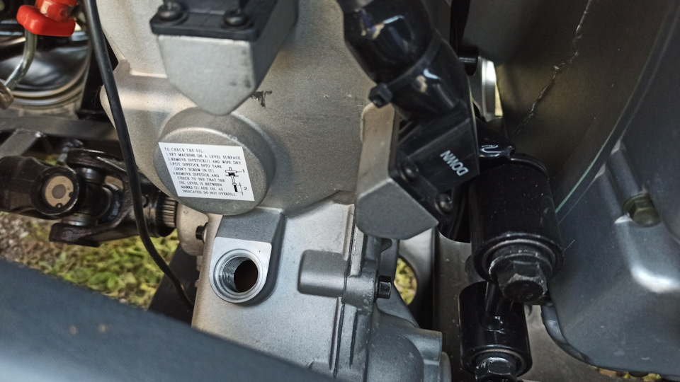
Полный размер
Место установки щупа раздатки
В раздатку заливается через щуп.
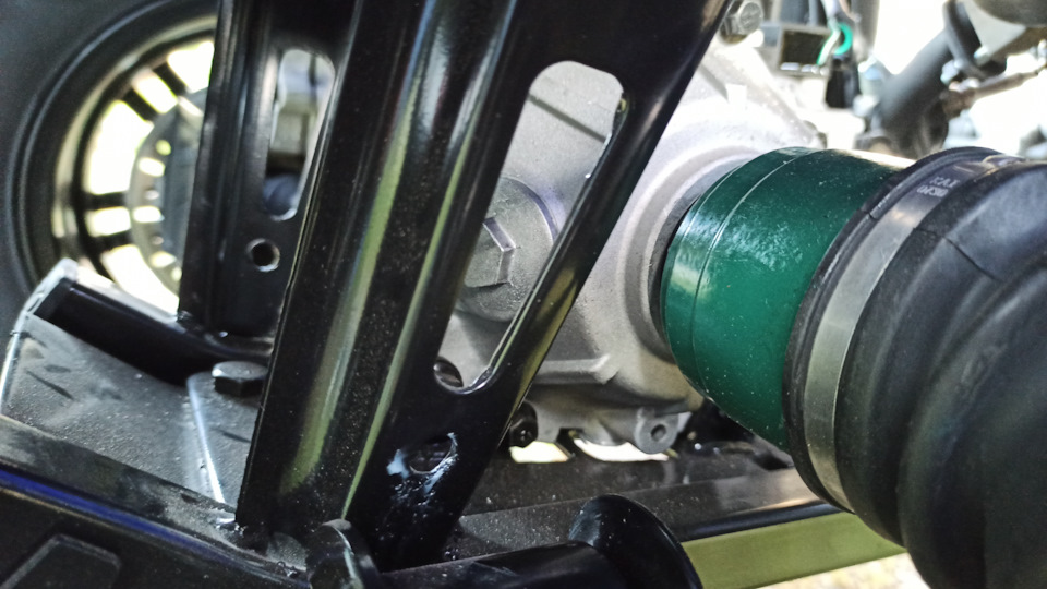
Полный размер
Заливная пробка переднего редуктора
С заменой масла в двигателе также ни каких проблем. Снизу откручивается сливная пробка, под которой прячется фильтр-сеточка, а заливается также через щуп. Кстати, полноценного масляного фильтра у этого двигателя нет, по этой причине интервал замены масла в двигателе гораздо меньше, чем у двигателей, где установлен масляный фильтр. Этот момент нужно учитывать. Мануал говорит, что масло в двигателе меняется через 30 моточасов.
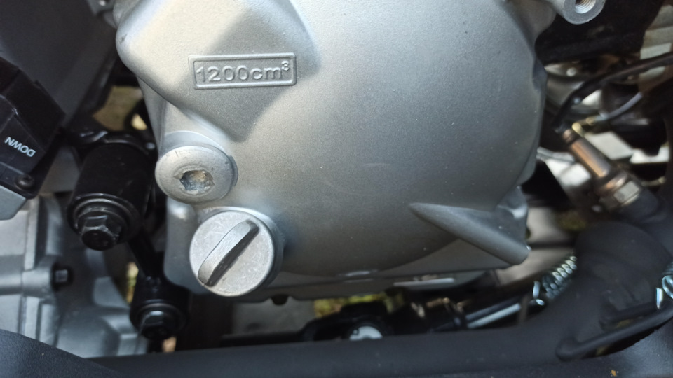
Полный размер
Масляный щуп двигателя и надпись, какой необходим объем масла
Антифриза в системе тоже что-то в районе 2-х литров. Сливал его тупо сняв патрубок с блока двигателя, ибо сливных кранов не предусмотрено.
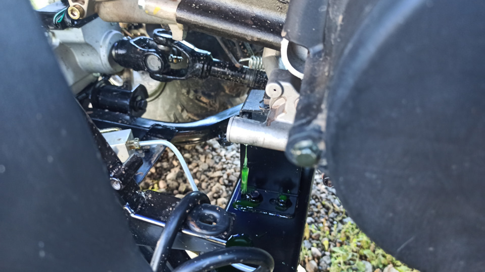
Полный размер
Процесс сливания антифриза
А вот с заливкой есть небольшие трудности. Заливная горловина радиатора находится под пластиковым кожухом-капотом, который так просто не снимается, но все возможно поменять и без снятия, главное сноровка.
Полный размер
Заливная горловина радиатора
Рукой можно подлезти и снять крышку радиатора, а через технологическую щель пластикового кожуха при помощи воронки антифриз спокойно заливается в систему.
Полный размер
Процесс заправки охлаждающей системы.
Также были прошприцованы все крестовины карданов (всего их 3 штуки, два на переднем и одна на заднем). Также шприцуются шаровые на передних стойках, это огромный плюс, может походят подольше.
И так, квадрик обслужен, теперь же настала очередь его эксплуатации, а вернее обкатки двигателя…
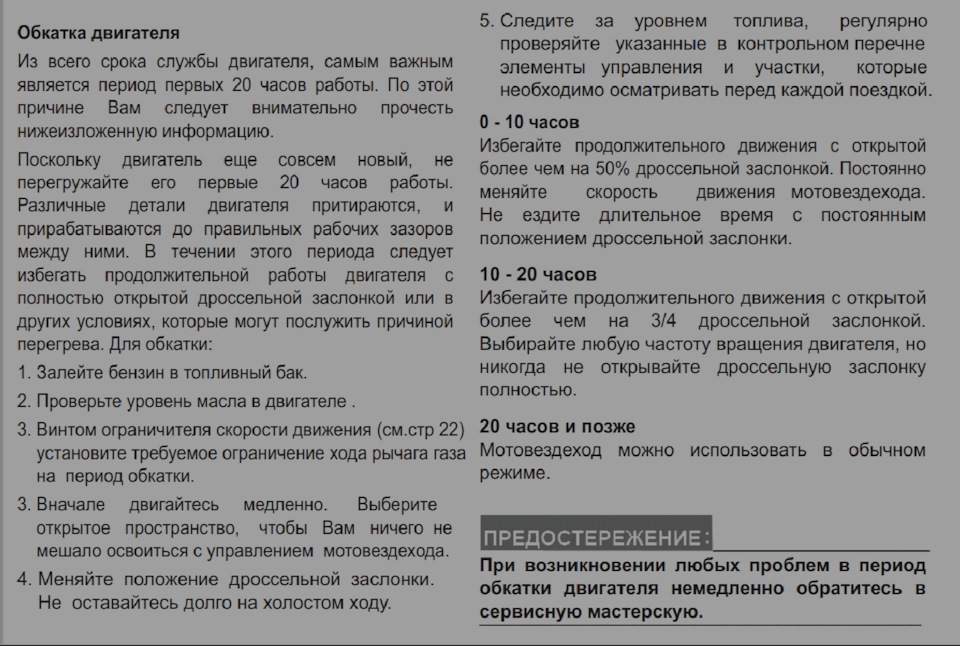
Полный размер
Из мануала как правильно обкатывать квадроцикл
Квадроцикл LINHAI M550L — универсальный внедорожник, который показывает безупречные результаты как во время досуга, так и при проведении хозяйственных работ.
Квадроцикл имеет одноцилиндровый четырехтактный двигатель с жидкостным охлаждением, мощностью 42 л.с.
Транспортное средство обладает блестящими характеристиками, качественной сборкой и комфортной комплектацией. LINHAI M550L способен покорить самые труднодоступные места. Квадроцикл оснащён АКПП, имеет возможность обратного хода, что придаёт лёгкости в управлении.
В интернет-магазине LINHAI вы сможете приобрести квадроцикл ЛИНХАЙ ЯМАХА M550L по самой низкой цене. Приобретая квадроцикл именно у нас, Вы получаете бесплатную доставку и гарантию от производителя по всей России. Мы сотрудничаем с LINHAI YAMAHA и являемся официальным дилером компании. В нашем шоу-руме Вы сможете пройти тест-драйв понравившегося квадроцикла.
Может кому полезно будет услышать про масла, у нас в редуктора линхая залито gl-4, про вязкость здесь речи не веду, вычитал что gl-5 в таком случае может оказаться губительным для узла, но до того как прочитать, в задний редуктор успел залить gl-5, спустя минут 10 катаний, открутил заливной болт глянуть уровень, а там оно вспенилось и с пузырьками воздуха (как хим. реакция) полезло под давлением наружу, в итоге купил лукой gl-4, полусинтетику 80w-90, 4 литра за 700 руб, залил в перед и зад, прокатился минут 15, потом слил и залил заново. Вот так промыл типа. Надеюсь 100 м. ч. теперь вспоминать про эти узлы не буду. В двигло так же залил лукойл полусинтетику 10w-40, в данном случае желающим промыть двигатель после старого масла, хотя при смене минералки на полусинтетику это делать не обязательно, рекомендую запастись ещё одним фильтром и таким же маслом на которое производим замену, смысл ненадолго после слива старого масла залить новое, покататься в течении дня, а затем опять заменить масло и фильт. Промывка химическим пятиминутками и т. Д. это совсем другая история, не актуальная для новых движков, т. К. в них уклон на раскоксовку и т. Д.
Успехов.