Особенности:
Пропускная способность 170 Мбит/с
Поддержка диапазона 2.402 — 2.492 ГГц
80,000 пакетов в секунду
Высокая выходная мощность радиомодуля— 28 дБм
Встроенная направленная панельная антенна с усилением 9 дБи
Мощная ОС
Интеллектуальный проприетарный поллинговый протокол iPoll 2
Интуитивно понятный пользовательский интерфейс, основанный на технологии HTML5
Монтаж на стену или мачту
LigoDLB 2-9
| Имя | Размер | Тип | |
|---|---|---|---|
|
Документация |
112KB | DLB | Загрузить |
|
Документация |
12.26MB | DLB | Загрузить |
|
Документация |
2.39MB | DLB | Загрузить |
|
Документация |
2.31MB | DLB | Загрузить |
|
Документация |
212KB | DLB | Загрузить |
|
Документация |
323KB | DLB | Загрузить |
Рекомендуемая дистанция:
Точка-Точка
Точка-Многоточка
Новая аппаратная платформа
Мощный процессор нового поколения обеспечивает более высокую производительность, предоставляя до 170 Мбит/с пропускной способности для пользовательских данных и увеличенную почти в два раза пакетную производительность — до 80000 пакетов в секунду. Поддержка узких каналов (ширина канала 5 и 10 МГц) обеспечивает устойчивую работу в условиях зашумлённого эфира. Увеличенный объём ОЗУ повышает производительность при большом количестве клиентов, а больший объём ПЗУ позволяет хранить запасной дополнительный образ прошивки для автоматического восстановления.
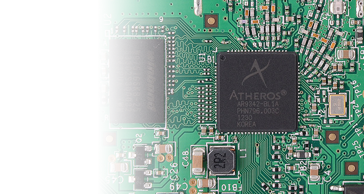
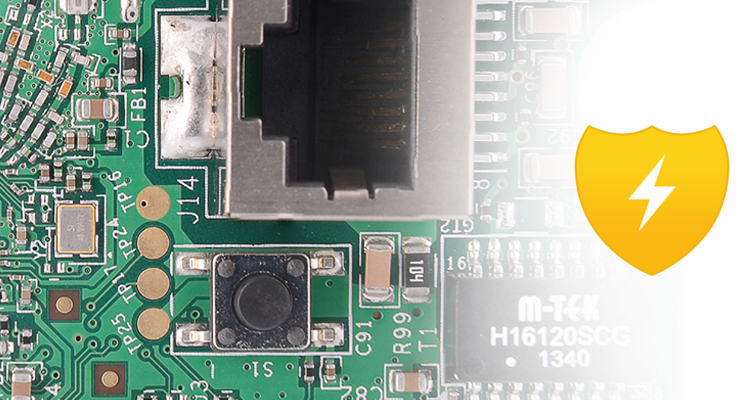
Встроенная защита от скачков напряжения
Защита 3 кВ линия-земля и 1 кВ линия-линия позволяет устройству работать в суровых погодных условиях и электрически нестабильных инсталляциях.
Новая ОС
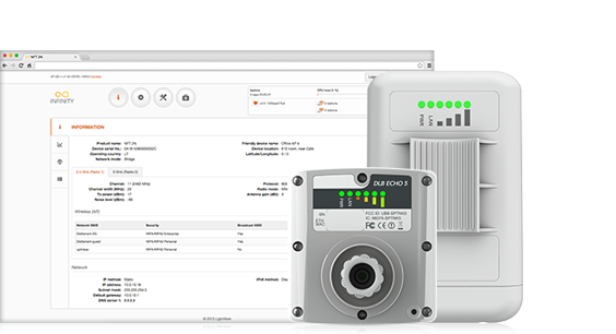
Новая операционная система включает в себя все функции, необходимые для построения сетей точка-многоточка. Отзывчивый пользовательский интерфейс построен на основе технологии HTML 5. Среди новых функций стоит отметить поддержку IPv6 в режимах bridge и router, протоколов обнаружения SSDP и Bonjour, гибкую систему ограничения пропускной способности и клиент SSTP. Новое поколение устройств — линейка LigoDLB – обладает обратной совместимостью с устройствами линейки APC фирмы Deliberant, в том числе в части использования проприетарного протокола iPoll — для работы просто обновите прошивку на устройствах (до версии 7.0 и выше).
iPoll 3 – улучшенный производительный протокол
Оптимизированный проприетарный протокол от LigoWave — это инновационное решение для устранения задержек передачи и взаимных помех в беспроводных сетях Точка-Многоточка.
Узнать больше
Поддержка сценария хотспот
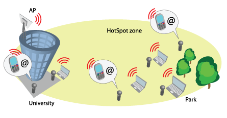
Начиная с версии 7.52 появилась возможность установить прошивку линейки Infinity на устройствах LigoDLB для использования их в качестве уличных хотспотов и подобных задач обеспечения доступа для потребительской электроники. После обновления прошивки, устройство DLB преобразуется в точку доступа для уличных хоспот-сетей и теряет и теряет функционал для провайдерских каналов точка-точка и сетей точка-многоточка.
Посмотреть инструкции
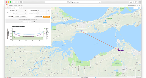
LinkCalc
LinkCalc — это свободный для использования калькулятор, который позволяет рассчитывать пропускную способность и планировать беспроводные уличные соединения. Пользователь может настраивать PtP- и PtMP-сети при помощи виртуальной карты, не проводя при этом полевых испытаний и не пользуясь специальными инструментами. Данные, которые предоставляет LinkCalc, можно также использовать для подсчёта количества потенциальных клиентов.
Войти Сейчас!
Универсальное, стабильное и эффективное устройство (с высокой выходной мощностью до 28 дБм) работает на частоте 2.4 ГГц, а также поддерживает стандарт 802.11n и технологию MIMO 2×2. Надёжный, качественный и небольшой по форм-фактору корпус в сочетании с направленной панельной антенной (9 дБи) — то, что нужно для работы на коротких и дальних расстояниях. (Про выбор радиоустройств линеек LigoDLB и LigoDLB ac по дальности связи читайте в нашей статье.)
Встроенная поддержка фирменного протокола iPoll 3 обеспечивает надёжную связь даже в густонаселённых районах (до 64-х устройств, подключённых к базовой станции).
Фирменная технология хранения резервного образа прошивки позволяет безопасно обновлять программное обеспечение устройства, не боясь отключения электроэнергии при этом процессе. В случае неудачного обновления прошивки устройство будет автоматически перезагружено с использованием резервной копии прошивки.
Корпус изготовлен из поликарбонатного пластика с УФ-ингибитором, что гарантирует долгосрочность наружного использования устройства под воздействием прямых солнечных лучей без риска поломки. LigoDLB 2-9 был протестирован на вибрацию, температуру, перепады, соль, туман и соответствием стандартам электрического перенапряжения, чтобы гарантировать высокий уровень надёжности устройства. Оснащён заземляющим наконечником и заземлённым PoE 24 В для профессионального монтажа и устойчивости к электрическим разрядам.
Особенности
- Поддержка диапазона 2.402–2.492 ГГц
- Высокая выходная мощность: 28 дБм
- Встроенная направленная панельная антенна с усилением 9 дБи
- Мощная операционная система
- Возможность крепления на мачту
Новая аппаратная платформа
Высокопроизводительный мощный процессор нового поколения обеспечивает скорость передачи данных до 170 Мбит/с, а обработки пакетов — до 80 000 пак/с. Поддержка узких каналов (ширина канала 5 и 10 МГц) гарантирует устойчивую работу в условиях зашумлённого эфира. Увеличенный объём ОЗУ повышает производительность при немалом количестве клиентов, а больший объём ПЗУ позволяет хранить запасной дополнительный образ прошивки для автоматического восстановления.
Встроенная защита от перенапряжения
Защита от электростатического разряда (3 кВ линия-земля и 1 кВ линия-линия) позволяет устройству работать в суровых погодных условиях и нестабильных электрических инсталляциях.
Новая ОС
Новая операционная система включает в себя все функции, необходимые для построения сетей точка-многоточка. Отзывчивый пользовательский интерфейс, построенный на основе технологии HTML 5. Среди новых функций стоит отметить поддержку IPv6 в режимах bridge и router, протоколов обнаружения SSDP и Bonjour, гибкую систему ограничения скорости трафика и клиент SSTP. Новое поколение устройств (линейка LigoDLB) обладает обратной совместимостью с устройствами линейки APC фирмы Deliberant, в том числе в части использования проприетарного протокола iPoll — для работы просто обновите прошивку на устройствах (до версии 7.0 и выше).
iPoll 3 — улучшенный производительный протокол
Собственный протокол — это инновационное решение для устранения задержек и помех при передаче данных в беспроводных PtMP-установках.
Поддержка сценария hotspot
Начиная с версии 7.52 появилась возможность установить прошивку линейки Infinity на устройствах LigoDLB для использования их в качестве уличных хотспотов и других связанных с ними приложений. После обновления микропрограммы устройство DLB преобразуется в точку доступа для уличных хоспот-сетей и теряет функционал для PtP- и PtMP-соединений.
Операционная система
Операционная система LigoDLB 2-9 обладает высокой функциональностью и проста в использовании. Это мощная и гибкая ОС, которая обеспечивает всем устройствам LigoDLB безупречную работу и облегчает развёртывание сетей.
- Интеллектуальный поллинговый протокол передачи данных (iPoll3)
- Двойной образ прошивки (в случае неудачного обновления прошивки устройство автоматически восстановит нормальную работу с использованием резервной копии прошивки)
- Новый интуитивно понятный веб-интерфейс, основанный на технологии HTML5
- 170 Мбит/с
- 80,000 пак/с
- Поддержка IPv6
-
Совместимость с WNMS
WNMS
WNMS — это бесплатно распространяемая система управления беспроводной сетью. Она упрощает большое количество задач, связанных с управлением и мониторингом сети. Комплексная система поддерживает несколько тысяч узлов в сети. Несколько сетей могут быть объединены в одну логическую и управляться с одного сервера. Большой набор функций позволяет быстро диагностировать проблемные участки, наглядно отображать сеть на карте, автоматически выполнять регулярные обновления прошивки, отслеживать состояния устройств, получать оповещения о проблемных узлах, просматривать статистику и т.д. WNMS поддерживает создание аккаунта для каждого пользователя. Несколько администраторов могут управлять различными сегментами сети на одном сервере, при этом не имея доступа к устройствам друг друга. WNMS доступна для операционной системы Windows и Linux как облачная система и в качестве мобильного приложения для устройств Android.
Рекомендации производителя по дальности применения
Технические характеристики
| Рекомендуемая максимальная дальность | В режиме PTMP — 3 км В режиме PTP — 5 км При максимальной скорости в режиме PTP — 2 км |
| Беспроводной стандарт | IEEE 802.11b/g/n, iPoll (проприетарный) |
| Защита от перенапряжения | 3 кВ линия-земля, 1 кВ линия-линия |
| Поддержка MIMO | Да, 2×2 |
| Диапазон частот | 2.402–2.492 ГГц |
| Мощность передатчика | До 20 дБм для РФ (до 28 дБм для других стран) |
| Чуствительность приёмника | От -95 до -76 дБм в зависимости от модуляции |
| Ширина канала | 5, 10, 20, 40 МГц |
| Схемы модуляции | 802.11 g/n: OFDM (64-QAM, 16-QAM, QPSK, BPSK) 802.11 b: DSS (CCK, DQPSK, DBPSK) |
| Скорости передачи данных | 802.11 n: 300, 270, 240, 180, 120, 90, 60, 30 Mbps 802.11 g: 54, 48, 36, 24, 18, 12, 9, 6 Mbps 802.11 b: 11, 5.5, 2, 1 Mbps |
| Коррекция ошибок | FEC, Selective ARQ |
| Схема дуплексирования | Time division duplex |
| Тип антенны | Встроенная панельная направленная |
| Усиление антенны | 9 дБи |
| Поляризация | Двойная линейная |
| Диаграммы направленности |
(изображение кликабельно) |
| Угол излучения в горизонтальной плоскости при горизонтальной поляризации | 60° |
| Угол излучения в горизонтальной плоскости при вертикальной поляризации | 60° |
| Угол излучения в вертикальной плоскости | 60° |
| КСВН | |
| Кросс-поляризационная развязка | 23 дБи |
| Проводной интерфейс | 1х 10/100 Base-T, RJ45 |
| Режимы работы | Точка доступа (Auto WDS), точка доступа iPoll 3, клиент (WDS, iPoll3), клиент (APR NAT) |
| Расширенная беспроводная функциональность | ATPC (автоматический контроль мощности передатчика), автоканал, автомодуляция, опрос клиентов по интеллектуальному методу |
| Беспроводная безопасность | WPA / WPA2 Personal, WPA / WPA2 Enterprise, WACL, изоляция пользователей |
| Беспроводной QoS | Приоритизация с 4 очередями |
| Сетевые режимы | Bridge, router iPv4, router IPv6 |
| Сетевые функции | Маршрутизация с и без NAT, VLAN, Firewall* |
| WAN | Static IP, DHCP client, PPPoE client |
| Сервисы | DHCP server, SNMP server, NTP client, RADVD, Ping Watchdog |
| Управление | HTTP(S) веб-интерфейс, SSH, чтение SNMP, WNMS, Telnet |
| Инструменты | Радиообследование объекта, тест канала, выравнивание антенны |
| Размеры | 140 х 90 х 35 мм |
| Вес | 122 г |
| Диаметр мачты | 35–60 мм (диаметры мачт для крепления устройств LigoWave) |
| Питание | 12–24 В DC, Passive PoE (100–240 В AC 18 В DC адаптер в комплекте) |
| Максимальная потребляемая энергия | 6 Вт |
| Температура окружающей среды рабочая | -40.. +65 °С |
| Влажность окружающей среды рабочая | 0.. 90% без конденсации |
| Мониторинг системы | SNMP v1/2c/3 server, Syslogs, системные оповещения на e-mail и SNMP trap |
* Настройка Firewall возможна только через командную строку (подключение по SSH) посредством iptables.
Характеристики радиочасти
| Выходная мощность (дБм) | |||||
| 802.11g | 802.11n/iPoll (20/40 МГц) | ||||
| 6 Мбит/c | 28 | 15 Мбит/c | 28 | 30 Мбит/c | 28 |
| 9 Мбит/c | 28 | 30 Мбит/c | 28 | 60 Мбит/c | 28 |
| 12 Мбит/c | 28 | 45 Мбит/c | 28 | 90 Мбит/c | 28 |
| 18 Мбит/c | 28 | 60 Мбит/c | 28 | 120 Мбит/c | 28 |
| 24 Мбит/c | 28 | 90 Мбит/c | 28 | 180 Мбит/c | 28 |
| 36 Мбит/c | 27 | 120 Мбит/c | 27 | 240 Мбит/c | 26 |
| 48 Мбит/c | 26 | 135 Мбит/c | 25 | 270 Мбит/c | 24 |
| 54 Мбит/c | 25 | 150 Мбит/c | 24 | 300 Мбит/c | 23 |
| Чувствительность приёмника (дБм) | |||||
| 802.11g | 802.11n/iPoll (20/40 МГц) | ||||
| 6 Мбит/c | -95 | 15 Мбит/c | -91 | 30 Мбит/c | -91 |
| 9 Мбит/c | -94 | 30 Мбит/c | -91 | 60 Мбит/c | -91 |
| 12 Мбит/c | -93 | 45 Мбит/c | -89 | 90 Мбит/c | -89 |
| 18 Мбит/c | -90 | 60 Мбит/c | -88 | 120 Мбит/c | -88 |
| 24 Мбит/c | -88 | 90 Мбит/c | -86 | 180 Мбит/c | -86 |
| 36 Мбит/c | -86 | 120 Мбит/c | -82 | 240 Мбит/c | -82 |
| 48 Мбит/c | -82 | 135 Мбит/c | -78 | 270 Мбит/c | -78 |
| 54 Мбит/c | -81 | 150 Мбит/c | -76 | 300 Мбит/c | -76 |
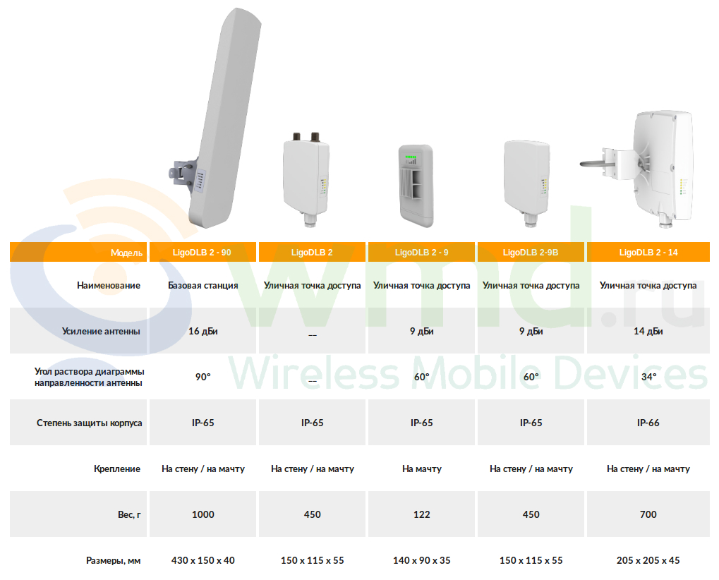
Сравнительная таблица
.png) |
.png) |
.png) |
|
| NanoStation M2 | NanoStation Loco M2 | LigoDLB 2-9 | |
| Усиление антенны | 11 дБи | 8.5 дБи | 9 дБи |
| Толщина | 60 мм | 60 мм | 40 мм |
Комплект поставки
| Точка доступа | 1 шт. |
| Кабель питания | 1 шт. |
| Пластмассовая стяжка | 2 шт. |
| PoE-адаптер питания (24 В 0.5 А) | 1 шт. |
Сравнительная таблица моделей диапазона 2.4 ГГц
На чтение 32 мин. Просмотров 1.9k.
Содержание
- Настройка Ligowave APC в режиме Point-to-Point (точка-точка)
- Настройка Ligowave APC в режиме Point-to-MultiPoint (точка-многоточка)
- Настройка Ligowave APC в режиме HotSpot
- Настройка Ligowave APC с разделением SSID по VLAN
- Настройка Ligowave APC в режиме беспроводного повторителя (репитера)
- Настройка Ligowave APC ограничение скорости трафика
- Настройка Ligowave APC в режиме роутера
- Настройка Ligowave APC проброс DHCP-сервера (DHCP relay)
- Настройка Ligowave APC PPPoE-клиент
- Настройка Ligowave DLB в режиме моста точка-точка
- Настройка Ligowave DLB в режиме моста точка-многоточка
- Настройка Ligowave DLB с ограничением подключаемых клиентов по MAC-адресу
- Настройка Ligowave DLB с управлением в отдельном VLAN
- Management and Data VLAN configuration
- Настройка Ligowave DLB в режиме роутера
- Setup CPE as a Router
- Router IPv4 Mode
- Router IPv6 Mode
- Parameters explanation
- Настройка Ligowave DLB в режиме PPPoE-клиента
- How to configure PPPoE client
- Parameters explanation
- Настройка Ligowave DLB в режиме HotSpot или беспроводного повторителя
- Настройка в режиме повторителя
Настройка Ligowave APC в режиме Point-to-Point (точка-точка)
It is recommended to use iPoll protocol for simple Point to Point network configuration.
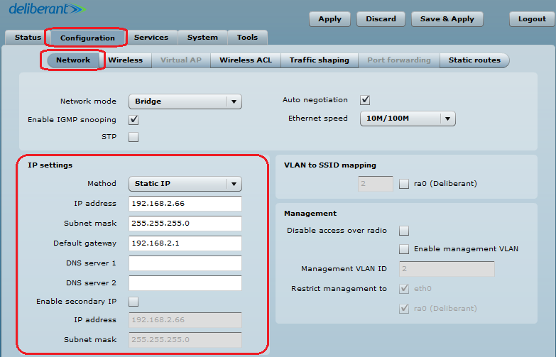
Follow the steps to create a simple Point to Point link between Access Point iPoll and Station (iPoll):
Step 1. Access Point iPoll configuration: change device’s default IP address (can be static or dynamic), enable IP alias if necessary:
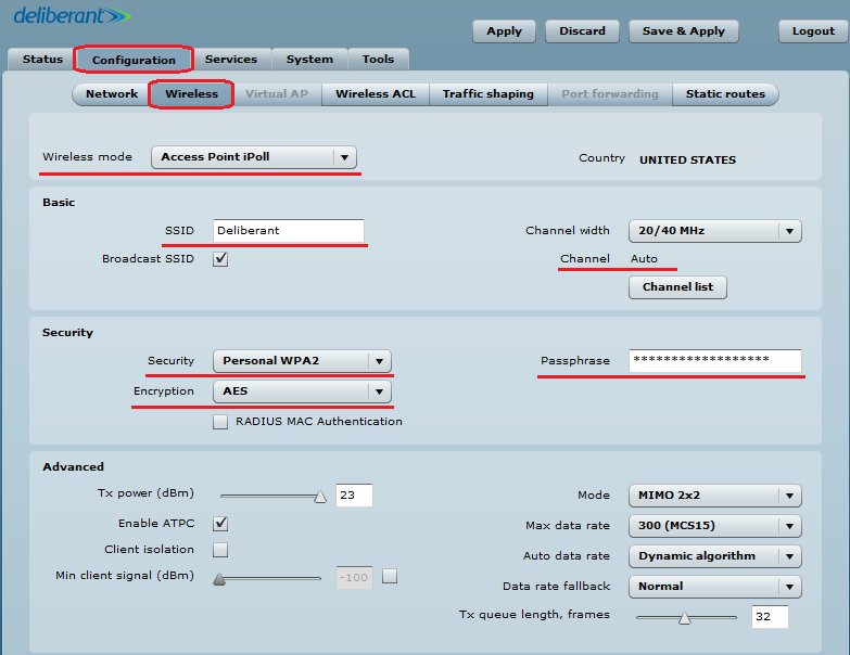
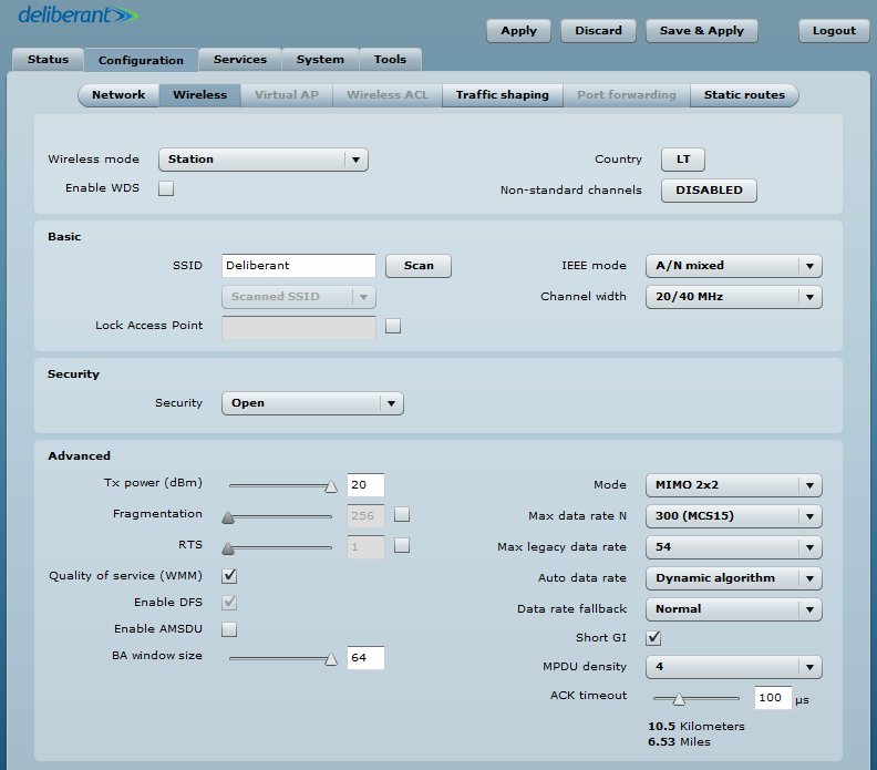
Step 2. Configure wireless settings for Access Point iPoll:– Select wireless mode: Access Point iPoll– Define SSID– Set channel: Auto– Enable Security for secure traffic on linkall other settings should be left default:
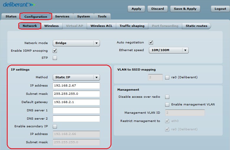
Step 3. Station iPoll configuration: change device’s default IP address (can be static or dynamic), enable IP alias if necessary:
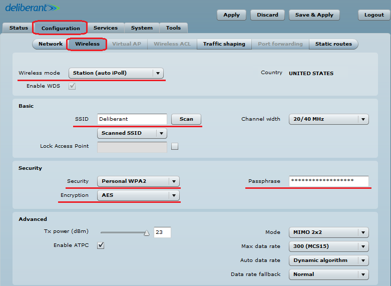
Step 4. Configure wireless settings for Station iPoll:– Select wireless mode: Station (auto iPoll)– Define SSID, or use “Scan” button to find iPoll Access Points automatically– Enable Security for secure traffic on linkall other settings should be left default: Note that Station iPoll security settings must conform the settings configured on the Access Point iPoll that station is associated with.
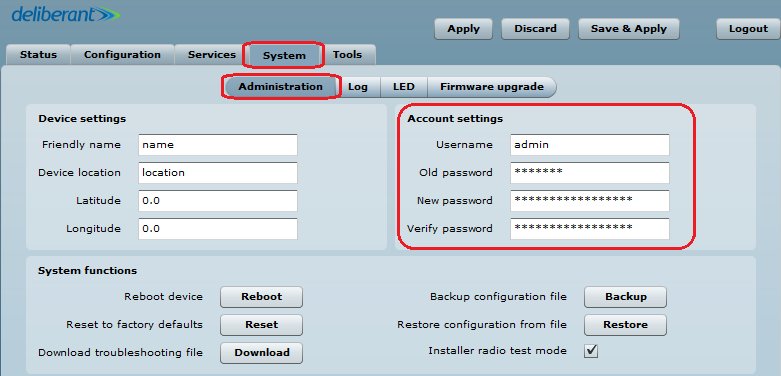
Step 5. It is highly recommended to change default administrator’s password for each unit:
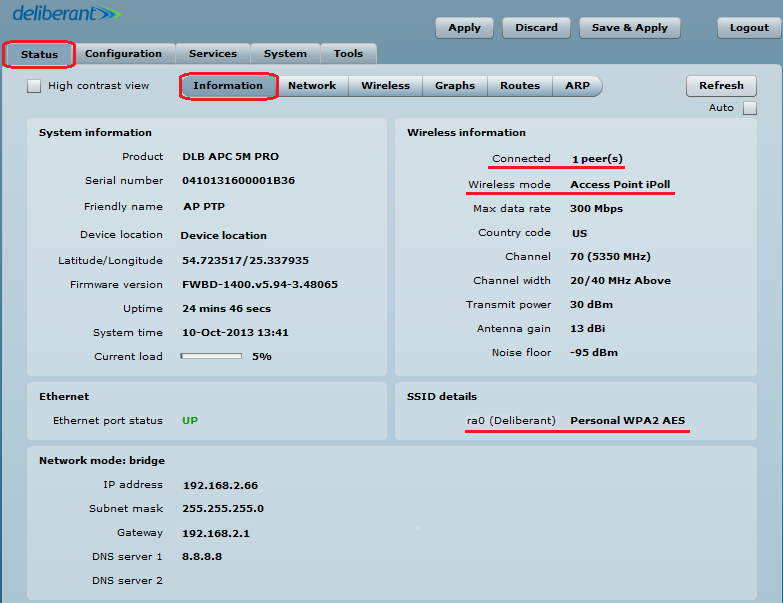
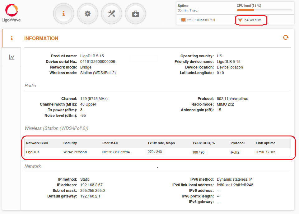
Step 6. Verify the PTP link connection. Navigate to the Status | Information page. The Information page will display wireless information of the link.
The status page of the Access Point iPoll must indicate that one peer (Station iPoll) is connected and information about connection must be displayed as follows:
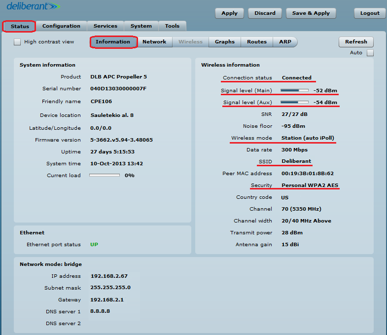
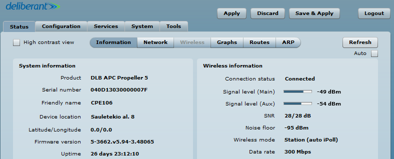
The status of the Station iPoll must be displayed as Connected and progress bars indicating the quality of the connection must be displayed:
Настройка Ligowave APC в режиме Point-to-MultiPoint (точка-многоточка)
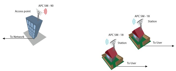
Point to Multipoint bridged network configuration
In a bridged (layer 2) network could be used in WDS or ipoll modes. Ipoll mode should be used when AP and all stations are Deliberant products otherwise select WDS mode. Recommended maximum stations per AP can be from 60 to 70.
Configuration
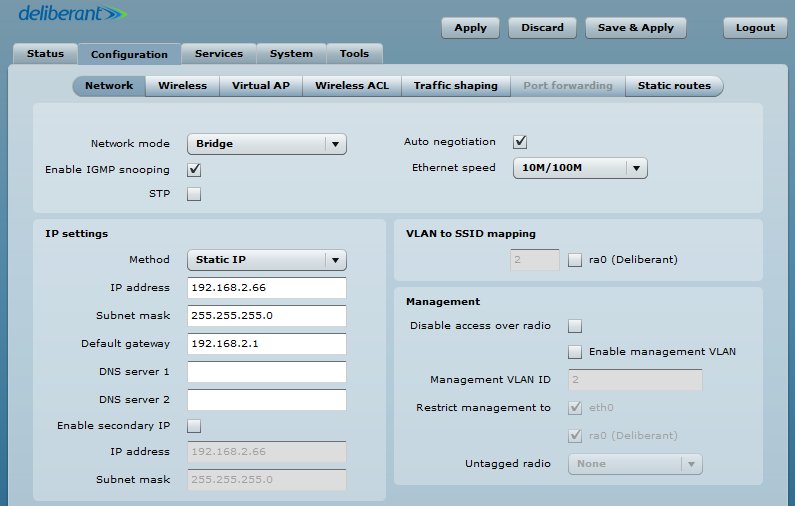
Change device’s IP address (can be static or dynamic), enable IP alias if necessary. Default ip address could be left because it is used for device management.
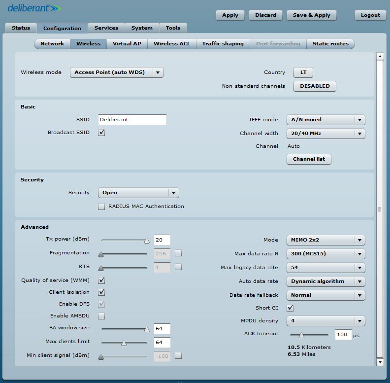
Access Point Wirelles section configuration steps:
- Select country code
- Select wireless mode: Access point WDS
- Define SSID
- Choose IEEE mode:
- N if you use 802.11n capable radios
- A/N mixed or B/G/N mixed if you also use legacy radios in your network
- Set channel to “Auto”
- Set Max data rate with Auto data rate “Dynamic algorithm”
- Enable Security if necessary
- Set ACK timeout based on the maximum distance from the station
- Leave all other settings as default
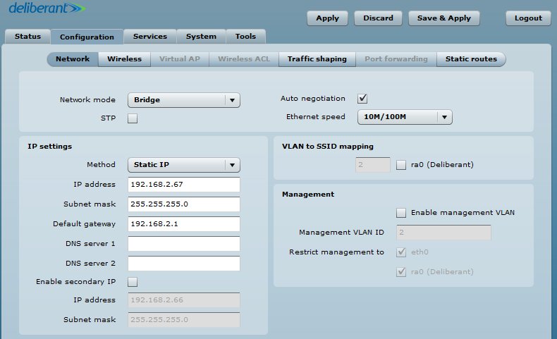
Configuration of the stations:Change device’s IP address (can be static or dynamic). Enable IP alias if necessary. All stations ip addresses should be in the same subnet as AP is.
Station Wirelles section configuration steps:-Select country code-Select wireless mode: Station WDS
According to access point:-Define SSID-Choose IEEE mode-Set Max data rate N to “Auto”-Enable Security if necessary-Set ACK timeout based on max distance from the station-Leave all other settings as default
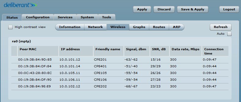
Observe signal levels at Access point and at Station. Recommended signal level range is from -35 to -60 dBm.If the device is MIMO, there are two signal streams. One of them is called as “Main” (Antenna 1), another is “Aux”
Main stream is mandatory. If main signal is very weak, the link will not be stable or will not work at all. It is necessary, to align the antennas for the best main signal. If Aux stream is weak, the link will work at lower data rate. Check if SNR is good on AP and Station and it is over 20/20.AP Point:
Station:
Настройка Ligowave APC в режиме HotSpot
The HotSpot scenario is popular in the various public places like an airport, shop, bar or stadium. The APC allows user authentication through external or internal Web portal. This authentication method is called UAM. User provides login credentials and then Web portal attempts to authenticate and authorize the client using the provided information. Client will not send any authentication requests directly to the APC, the Web portal will do this. On success, APC will allow access to the Internet; otherwise Web portal will display failure notice.
Follow the steps to configure a Hotspot UAM authentication through external Web portal, for wireless clients.
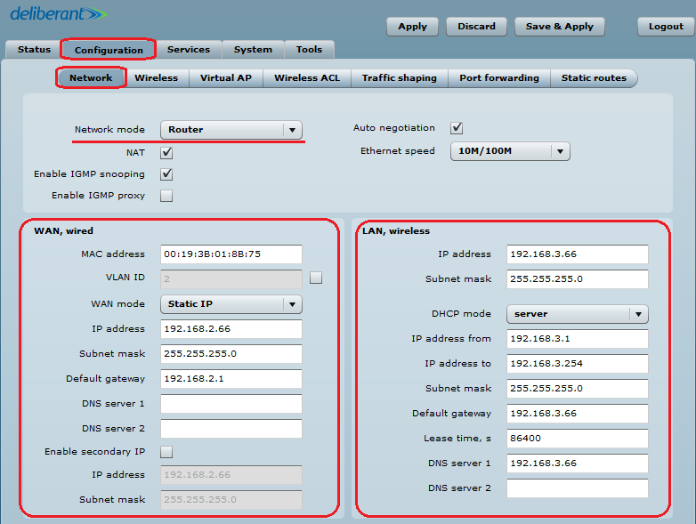
Step 1. Configure network settings: the HotSpot with UAM authentication is available only if APC operates as Router.
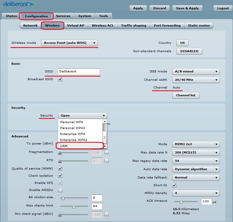
Step 2. Setup wireless settings for HotSpot:– Select wireless mode: Access Point (auto WDS)– Define SSID– Set channel: Auto– Choose wireless security: UAM
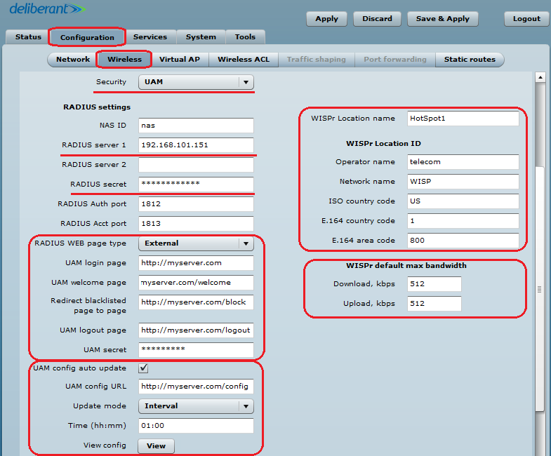
Step 3. Setup UAM authentication with External web/login page (hosted on separate web server):-Add at least one RADIUS server settings: IP addres, RADIUS secret, authentication and accounting ports
-Setup the External UAM fields: login page URL, welcome page URL, blacklist URL and logout URL
-UAM configuration can be automatically updated from the server at scheduled time
-UAM supports Hotspot description according to WISPr 1.0 recommendation: WISPr location name, operator name, network name, ISO country code, E.164 country code, E.164 area code
-UAM supports traffic limitation and has fields for default bandwidth definition. These parameters/attributes can be overridden per user from the RADIUS.
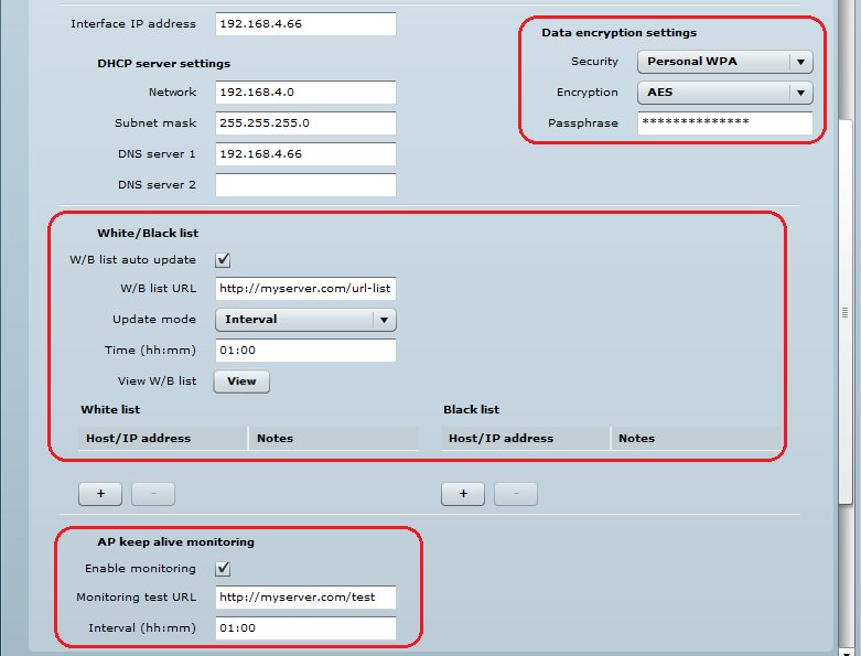
Step 4. Additionally the following settings can be configured for the UAM autrhentication:-WPA-PSK encryption can be used on UAM for a stronger security-UAM supports white/black list which can be configured statically on the device or can be updated automatically from the server-UAM has an option for AP monitoring through HTTP URL
Step 5. After the UAM authentication is successfully configured on the APC, all wireless clients will be redirected to the External Web portal for authentication.
Настройка Ligowave APC с разделением SSID по VLAN
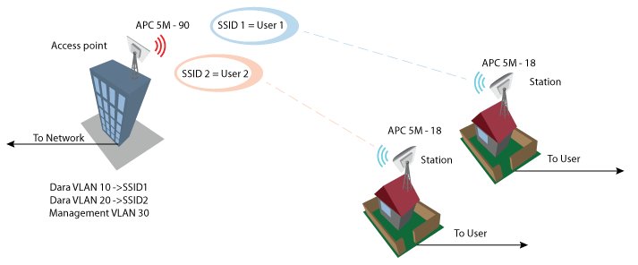
Virtual AP
Virtual AP functionality is available only in Access Point (auto WDS) wireless mode.
Use the Configuration | Virtual AP page to configure to create up to 7 additional Virtual AP interfaces. The Virtual AP defines a logical wireless network, and the APC can be configured to provide additional 7 wireless networks on each device radio. All the VAPs may be active at the same time meaning that client devices can associate to the APC using any of the VAP SSID.
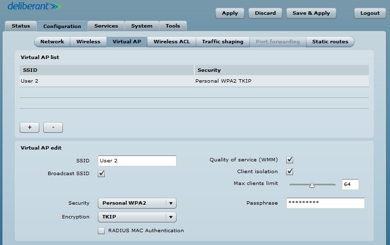
The Virtual AP table displays a summary of all virtual radio interfaces running on the APC:
To create a new Virtual AP, click on + button to add new entry on the VAP table, then select this entry and specify required parameters:
SSID – specify the unique name for the VAP [string].
Broadcast SSID – when this option is selected the particular SSID is visible during network scans on a wireless station. When unselected, the VAP SSID is not visible and not broadcasted to wireless stations.
Quality of service (WMM) – enable to support quality of service for prioritizing traffic.
Client isolation – enable the user Layer 2 isolation. The Layer 2 isolation blocks the wireless clients from communicating with each other.
Max clients limit – specify the maximum number of associated wireless clients per VAP.
Each VAP security is configured by default as an “open system”, which broadcasts a beacon signal including the configured SSID. For more secure network choose one of the security mechanisms for each VAP interface.
Security – choose the wireless security and encryption method from the drop-down list.Wireless clients must be able to respond with a specific security configuration
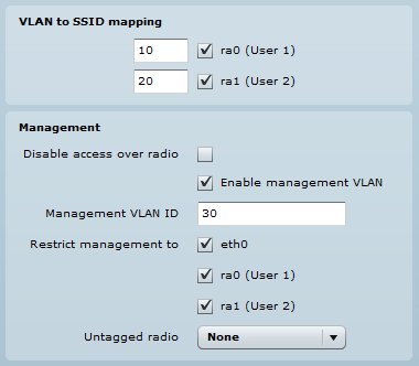
VLAN to SSID mapping
Virtual Local Area Networks (VLANs) are logical groupings of network resources.
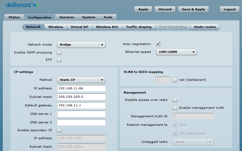
VLAN to SSID mapping – specify the VLAN ID for traffic tagging on required radio interface [2-4095]. The Station devices that associate using the particular SSID will be grouped into this VLAN. Configuration window is in Configuration/Network section. When device interfaces are configured with a specific VLAN ID value in Management section, only management frames that matching configured VLAN ID will be accepted by device. Restrict management is used when stations have to be management via VLAN too.
Network management is available only on Bridge network modeFor IP eth0 is mandatory because it is interface to the networkWhen you specify a new management VLAN, your HTTP connection to the device will be lost. For this reason, you should have a connection between your management station and a port in the new management VLAN or connect to the new management VLAN through a multi-VLAN router
Настройка Ligowave APC в режиме беспроводного повторителя (репитера)
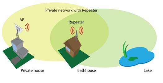
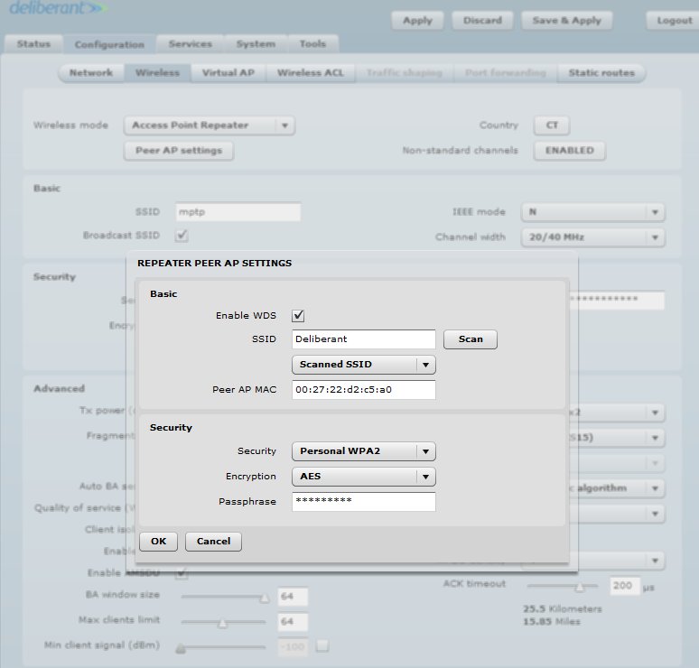
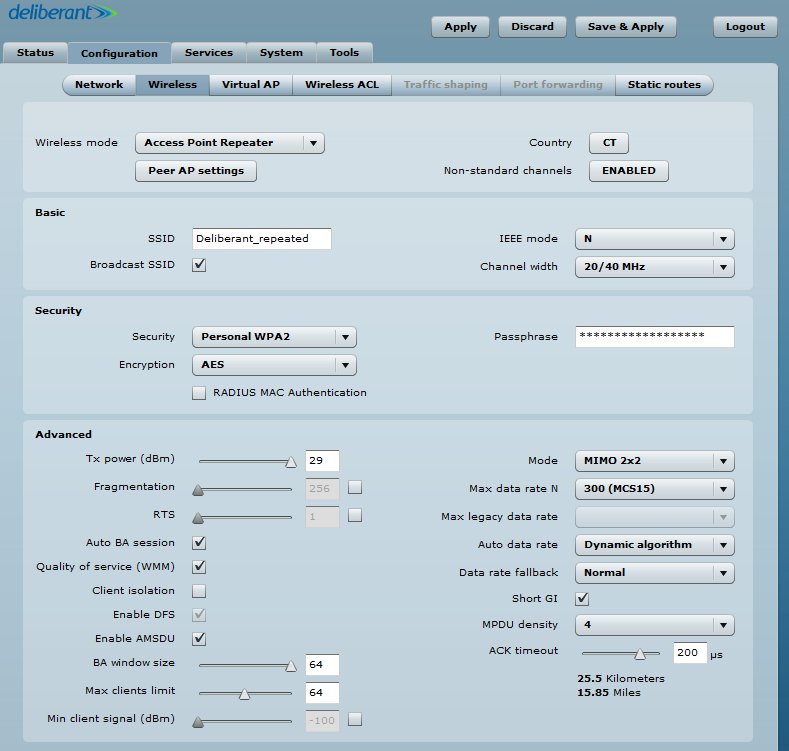
Use Access Point Repeater mode in order to extend the range of the existing network infrastructure. The Access Point repeater’s wireless settings has possibility to scan SSID of the surrounding APs and choose the required one. Enable WDS when the main AP is working in WDS mode too. Do not forget to add security information which is needed to connect to main AP. Also country code should be the same on all devices.
Repeater Basic Wireless Settings
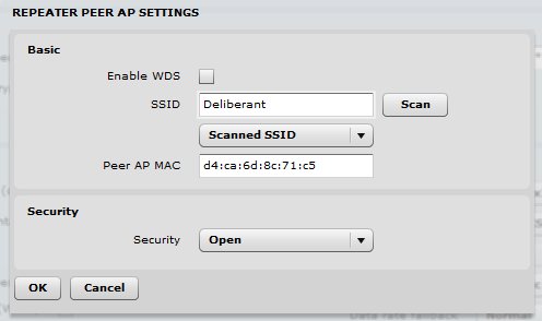
SSID – specify the SSID of the remote access point.
Enable/Disable WDS – specifies Access Point Repeater mode WDS or non WDS
Scan – click this button to scan for surrounding wireless networks. Found network SSID’s will be available in drop down menu.
Peer Access Point MAC address – enter the MAC address of the remote access point.
Broadcast SSID – enable or disable the broadcasting of the SSID.
IEEE mode – specify the operating wireless mode.
Channel width – The default channel bandwidth for 802.11 radio is 20MHz. The 802.11n allow channel bonding in such way the total channel width becomes 40MHz.
1. Set wireless mode to Access Point Repeater and go into Peer AP settings
2. Scan and choose AP SSID which is going to be repeated.
Both sides (AP and Repeater Peer) of the link must have the same security settings.
3. In Basic and Security sections there could be added the same as main AP SSID and Security information or created new one.
WDS mode should be disabled when main AP is working in regular non WDS mode. Commonly used when trying to repeat simple wireless router.
Настройка Ligowave APC ограничение скорости трафика
Traffic Limiting
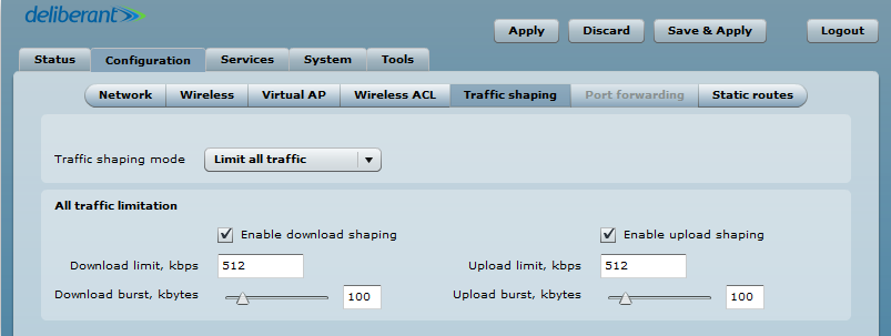
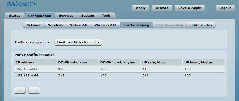
Use Traffic Shaping to control download or upload bandwidth in order to optimize or guarantee performance. There are two methods to control network traffic:
Limit all traffic – limits overall APC upload and download traffic.
Limit per IP traffic – limits upload and download traffic for a specified IP addresses.
Limit all traffic
Enable download shaping – select to enable limitation of the download traffic.
Download limit, kbps – specify the maximum download bandwidth value in Kbps.
Download burst, kbytes – specify the download burst size in kbytes.
Enable upload shaping – select to enable limitation of the upload traffic.
Upload limit, kbps – specify the maximum upload bandwidth value in Kbps.
Upload burst, kbytes – specify the upload burst size in kbytes
Limit per IP traffic
Use + button to create new traffic limitation rules:
IP address – specify IP address for which the traffic will be limited.
Down rate, kbps – specify the maximum download bandwidth value in Kbps.
Down burst, kbytes – specify the download burst size in kbytes.
UP rate, kbps – specify the maximum upload bandwidth value in Kbps.
UP burst, kbytes – specify the download burst size in kbytes
Настройка Ligowave APC в режиме роутера
Setup CPE as a Router
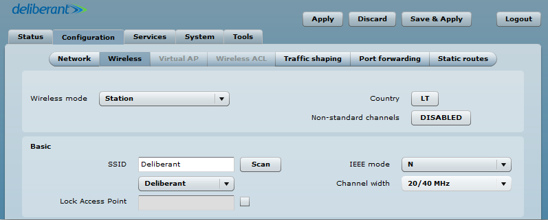
Step 1. Navigate to the Configuration | Wireless tab, choose Station wireless mode, click Scan button near the SSID entry field to choose the SSID of the AP where the station will be associated to. Specify the Security parameters for the AP, check IEEE mode (these settings must conform with AP wireless settings) and click Save&Apply:
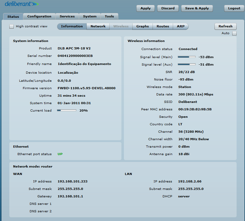
Step 2. Verify connection. Navigate to the Status | Information page. The Information page will display wireless information of the link with access point. The connection status must be displayed as Connected and progress bars indicating the quality of the connection must be displayed:
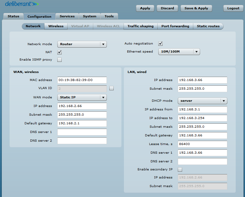
Step 3. Router Mode. This section allows customizing parameters of the Router to suit the needs of network, including ability to use the built-in DHCP server. When device is configured to operate as Router, the following sections should be specified: WAN network settings, LAN network settings and LAN DHCP settings.
Step 4. WAN Settings WAN network settings include settings related to the WAN interface. In this scenario WAN interface is from wireless side. The access type of the WAN interface can be configured as: Static IP, Dynamic IP, PPPoE client. WAN mode – choose Static IP to specify IP settings for device WAN interface:Set static IP from the same subnet as is AP device. Then you could reach station from your netwrok
Step 4. DHCP mode – choose server to enable DHCP server on LAN interface.In IP address field set address with which you could reach device via wired LAN
IP address from – specify the starting IP address of the DHCP address pool.
IP address to – specify the ending IP address of DHCP address pool.
Subnet mask – specify the subnet mask.
Default gateway – specify DHCP gateway IP address.
Lease time – specify the expiration time in seconds for the IP address assigned by the DHCP server.
DNS server – specify the DNS server IP address.
Настройка Ligowave APC проброс DHCP-сервера (DHCP relay)
DHCP Relay configuration example
What is DHCP relay mode? The DHCP relay forwards DHCP messages between subnets with different sublayer broadcast domains.
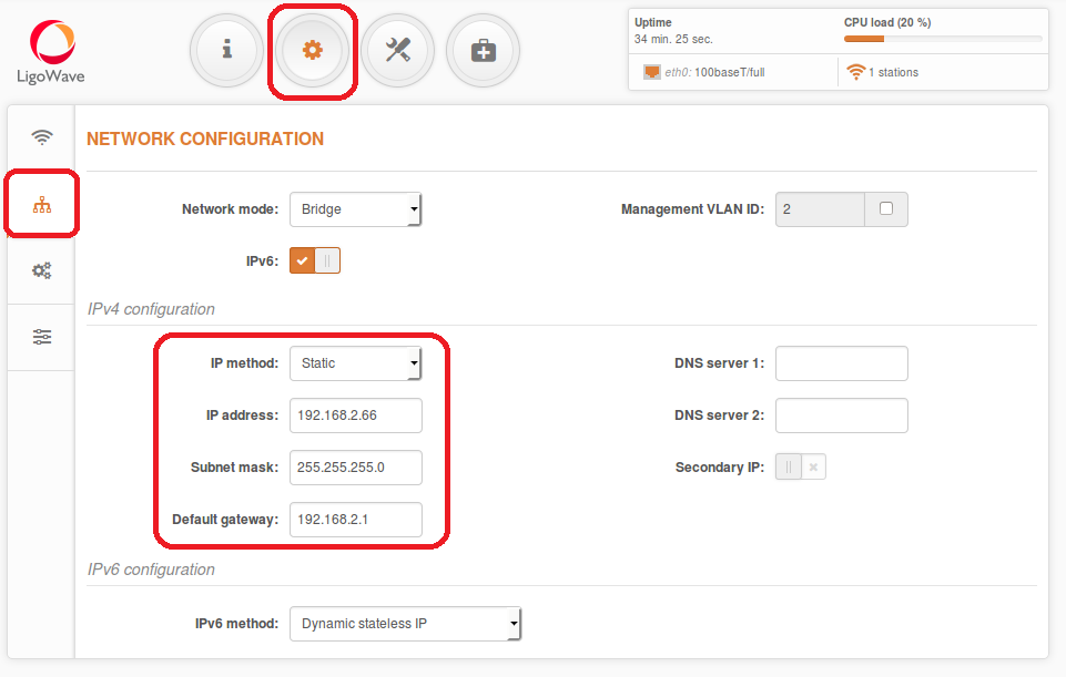
Step 1. Configure AP as bridge with IP 192.168.11.66 netmask 24, GW 192.168.11.1
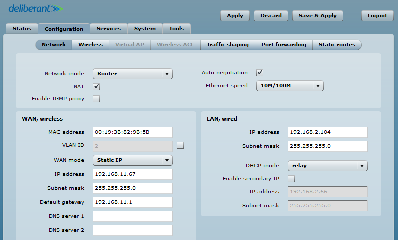
Step 2. Configure CPE as a Router and connect It to AP. Setup DHCP mode as relay. Static WAN, wireless IP address is from the same subnet as AP which lets to reach device via wireless. LAN, wired IP address is used to reach device from LAN side and should be from the DHCP server subnet.
How to test on Linux
DHCP relay link configuration could be tested in various ways what is needed are DHCP server, router
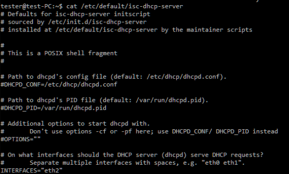
Step 1. Install DHCP server on your linux pc:
sudo apt-get install isc-dhcp-server
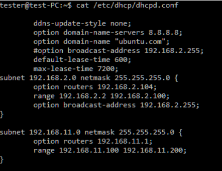
Step 2. Configure DHCP server as following:
Step 3. Step four: configured DHCP server with IP on eth2 interface. IP on eth2: 192.168.11.1 netmask 24, GW 192.168.11.1
Step 4. Step six. Add static route on DHCP server in order to reach x.2.0 LAN with “sudo route add –net 192.168.2.0 netmask 255.255.255.0 gw 192.168.11.1
Step 5. Test the configuration.
Настройка Ligowave APC PPPoE-клиент
How to configure PPPoE client
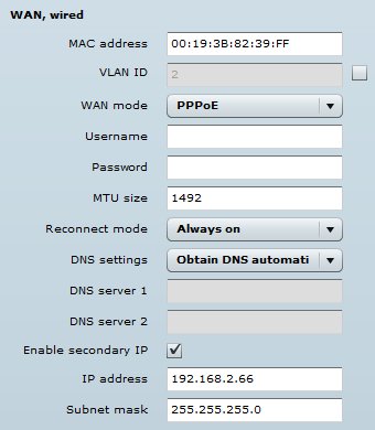
In router mode the DLB APC will receive internet through WAN port and will share it to the LAN ports that will be separated with a different IP range. The type of connection to the WAN interface can be made by Static IP, DHCP client or PPPoE.
WAN mode – choose PPPoE to configure WAN interface to connect to an ISP via a PPPoE. In main configuration should be added Username, Password all other settings should be left by default:
Parameters explanaition:
MAC address – specify the clone MAC address if required. The ISPs registers the MAC address of the router, and allows only that MAC address to connect to their network. In such case if there is need to change hardware (router), you need to notify your ISP about MAC address change, or simply set the router’s MAC address to the MAC address of the previously router/computer.
VLAN ID – specify the VLAN ID for traffic tagging on required radio interface [2-4095]. The Station devices that associate using the particular SSID will be grouped into this VLAN.
User name – specify the user name for PPPoE.
Password – specify the password for PPPoE.
MTU – specify the MTU (Maximum Transmission Unit). The default value is 1500 bytes.
Reconnect mode – specify PPPoE reconnection mode:
- Always on – PPPoE connection automatically starts without timeout. The router will keep trying to bring up the connection if it is disconnected for some reason.
- On demand – the PPPoE connection automatically starts when there is outbound traffic to the Internet, and it automatically terminates if the connection is idle based on the value specified in the Idle time [1-65535] setting.
DNS settings – allows selecting if automatically assigned or alternative DNS servers should be used.
Enable IP alias – specify the alternative IP address and the netmask for APC unit management.
Настройка Ligowave DLB в режиме моста точка-точка
It is recommended to use iPoll 2 protocol for simple Point to Point network configuration.
Follow the steps to create a simple Point to Point link between Access Point iPoll2 and Station (WDS/iPoll2):
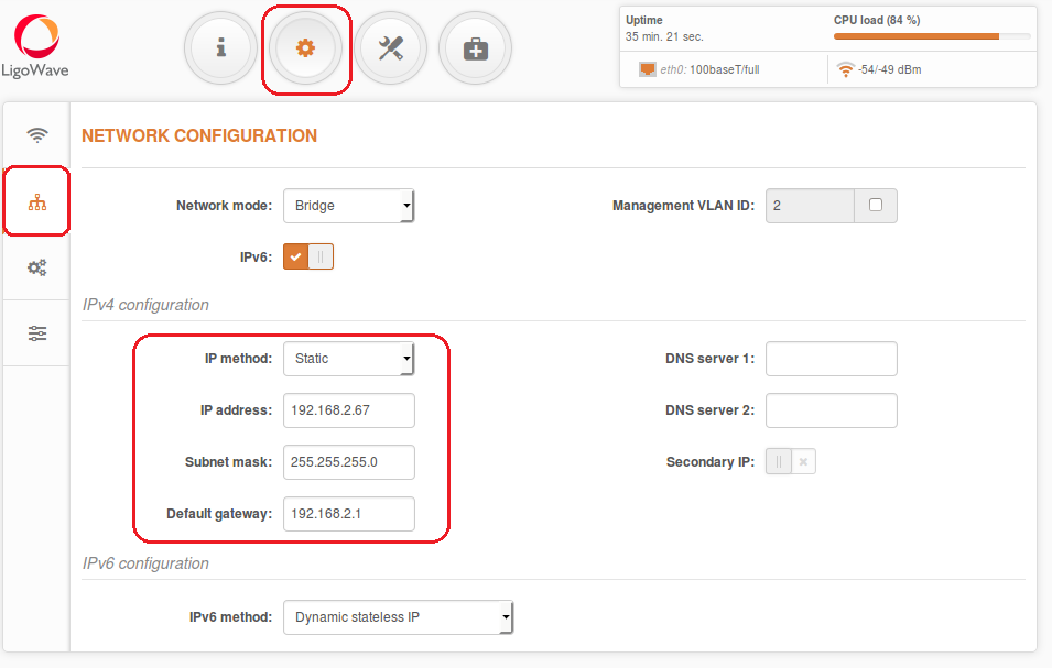
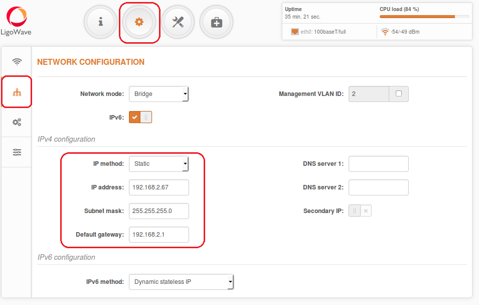
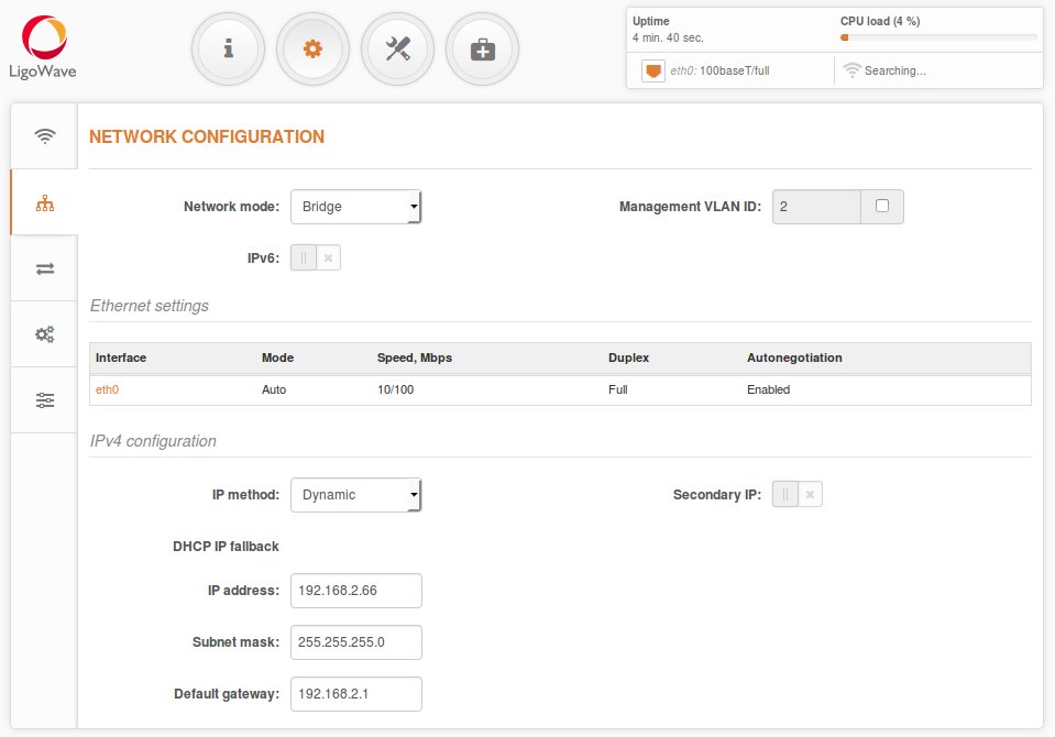
Step 1. Access Point iPoll 2 configuration: change device’s default IP address (can be static or dynamic), enable IP alias (Secondary IP) if necessary:
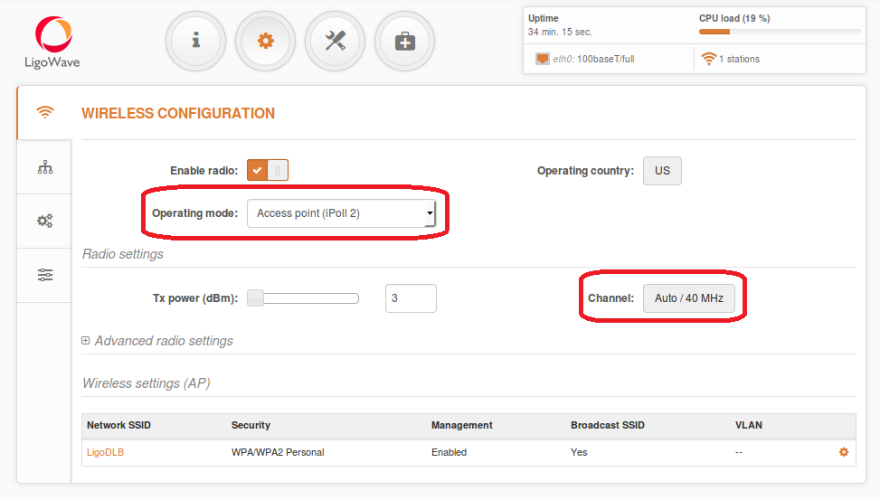
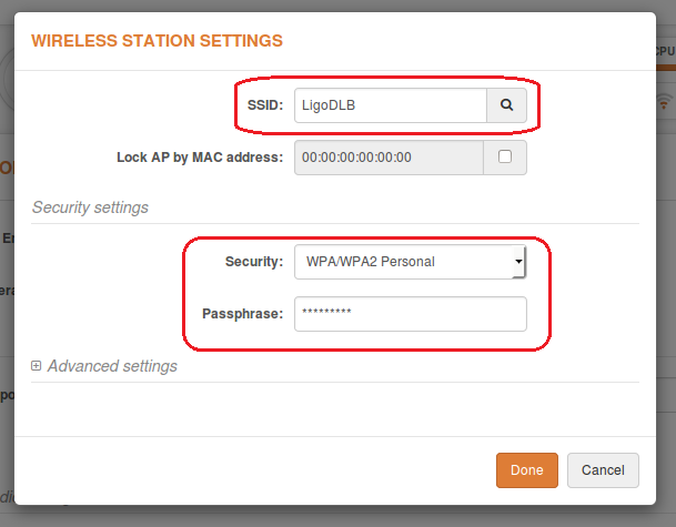
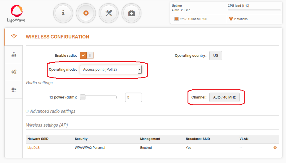
Step 2. Configure wireless settings for Access Point iPoll 2:– Select wireless mode: Access Point iPoll– Set channel: Autoall other settings should be left default:
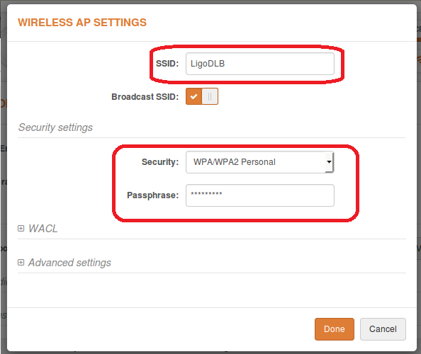
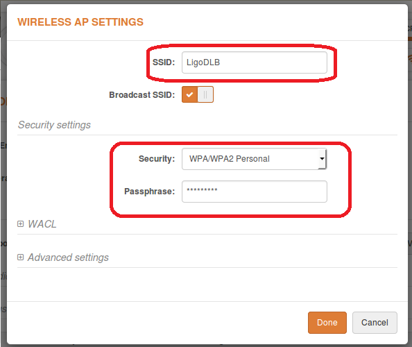
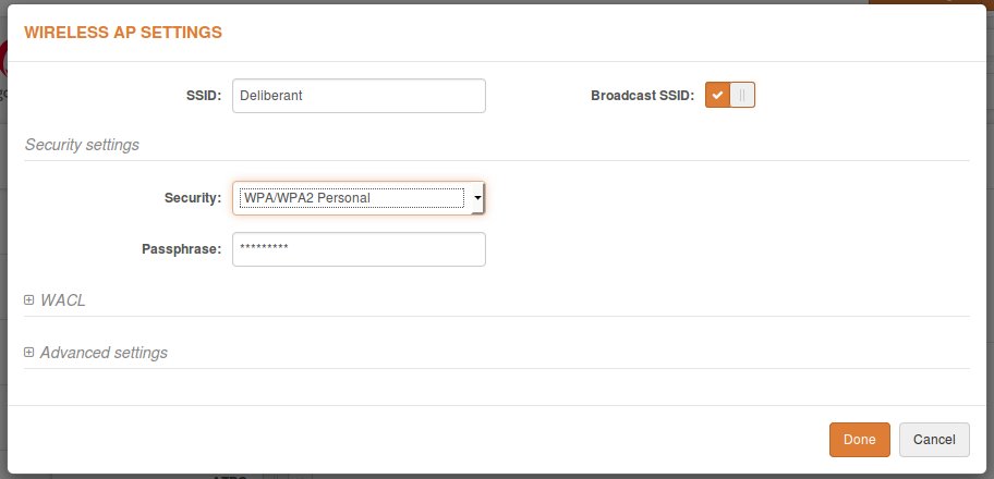
Enter the following button in Wireless settings (AP) section to change SSID and Encryption configuration
– Define SSID– Enable Security for secure traffic on link all other settings should be left default:
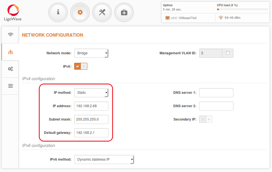
Step 3.Station iPoll 2 configuration: change device’s default IP address (can be static or dynamic), enable IP alias (Secondary IP) if necessary:
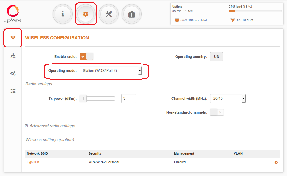
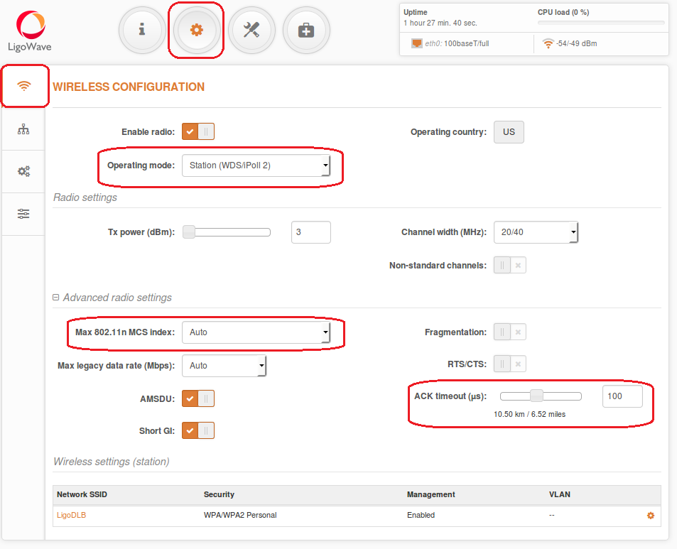
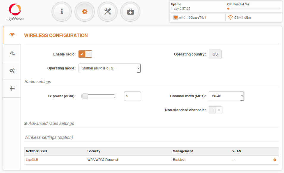
Step 4. Configure wireless settings for Station iPoll 2:– Select wireless mode: Station (WDS/iPoll 2)all other settings should be left default:
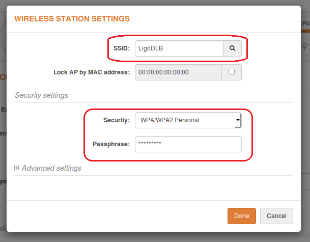
Enter the following button in Wireless settings (station) section to change SSID and Encryption configuration
– Define SSID, or use “Scan” button to find iPoll 2 Access Points automatically– Enable Security for secure traffic on link all other settings should be left default:
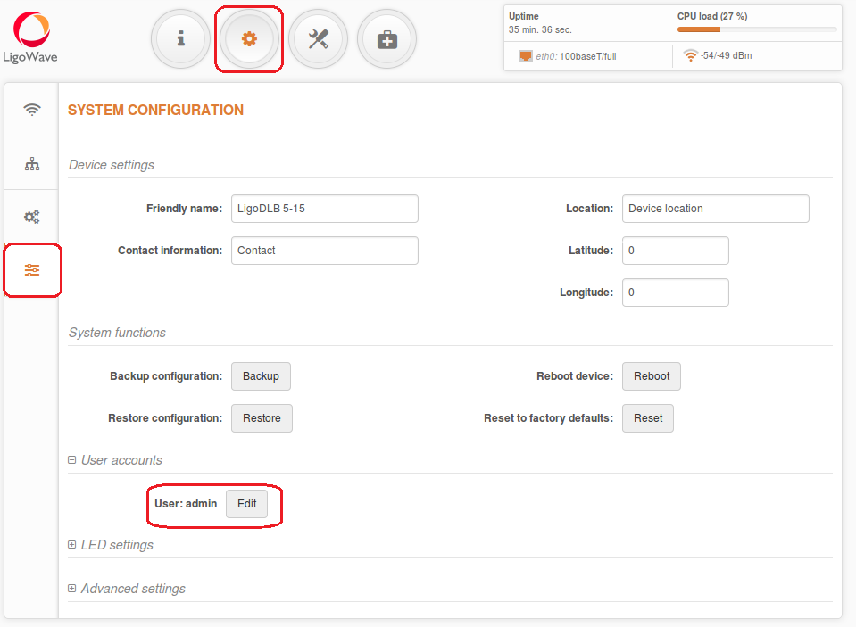
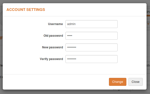
Note that Station iPoll 2 security settings must conform the settings configured on the Access Point iPoll 2 that station is associated with. Step 5. It is highly recommended to change default administrator’s password for each unit:
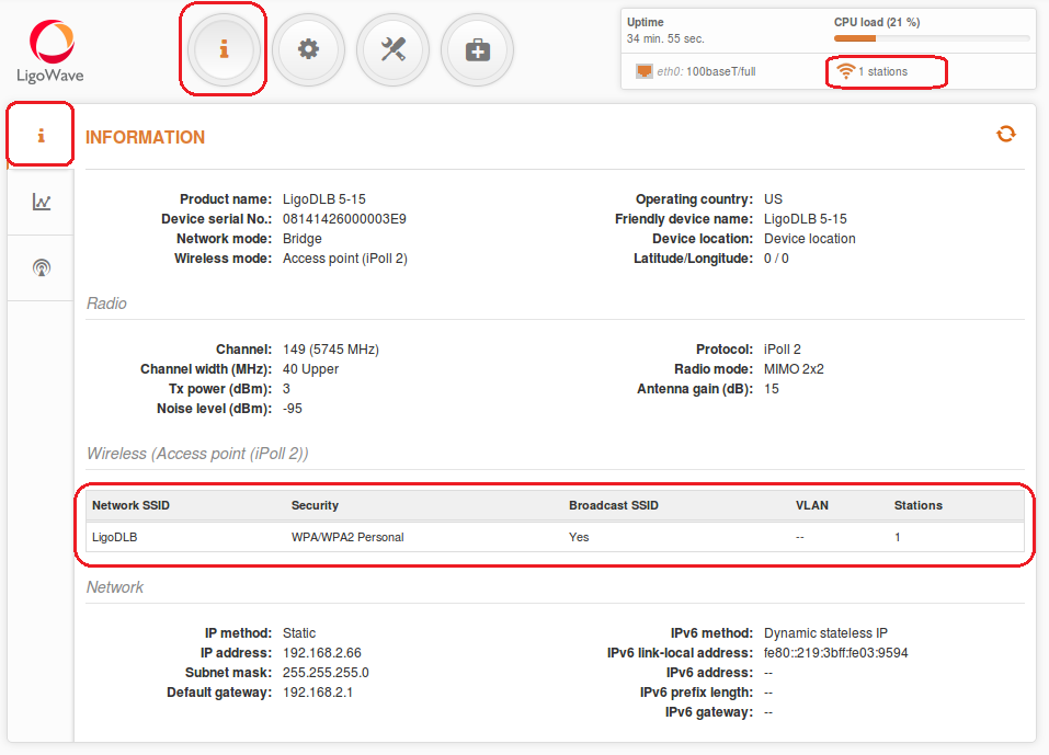
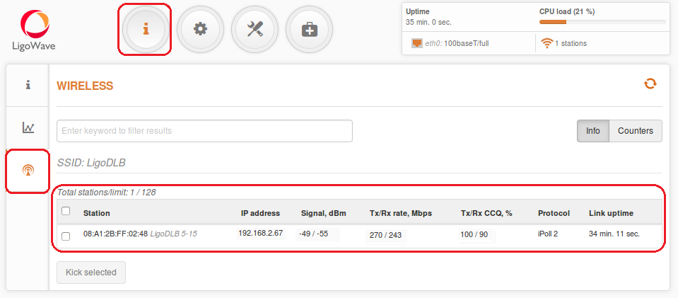
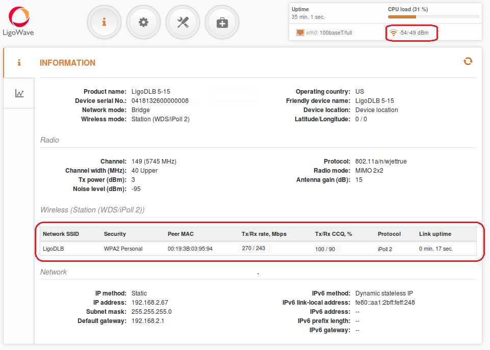
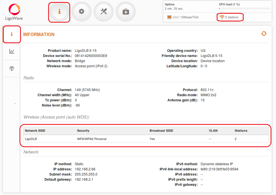
Step 6. Verify the PTP link connection. Navigate to the Status | Information page. The Information page will display wireless information of the link.
The status page of the Access Point iPoll 2 must indicate that one peer (Station iPoll 2) is connected and information about connection must be displayed as follows:
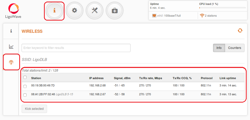
Detailed information about connected peers stays at Status | Wireless page.
The status of the Station iPoll 2 must be displayed as Connected and progress bars indicating the quality of the connection must be displayed:
Настройка Ligowave DLB в режиме моста точка-многоточка
Point to Multipoint bridged network configuration
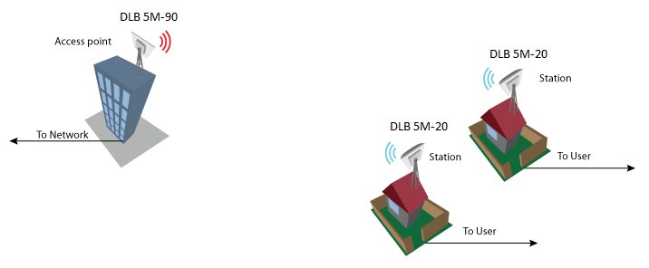
In a bridged (layer 2) network could be used in WDS or ipoll 2 modes. Ipoll 2 mode should be used when AP and all stations are Deliberant products otherwise select WDS mode. Recommended maximum stations per AP can be from 60 to 70.
WDS mode Configuration
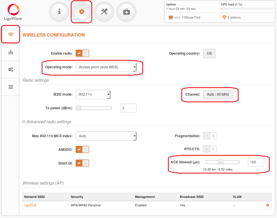
Change device’s IP address (can be static or dynamic), enable IP alias (Secondary IP) if necessary. Default ip address could be left because it is used for device management. Configure wireless settings for 11N AP:– Select wireless mode: Access point (auto WDS)
– Choose IEEE mode:
N if you use 802.11n capable radios
A/N mixed or B/G/N mixed if you also use legacy radios in your network
– Set channel to “Auto”
– Set ACK timeout based on the maximum distance from the station, using the slide:
– Define SSID
– Enable Security if necessary
iPoll 2 mode Configuration
Configure wireless settings for iPoll 2 master:– Select wireless mode: Access Point iPoll– Define SSID– Set channel to “Auto”– Enable Security if necessaryall other settings should be kept default:
Configuration of the stations:Change device’s IP address (can be static or dynamic). Enable IP alias (Secondary IP) if necessary. All stations ip addresses should be in the same subnet as AP is.
Change second device’s IP address (can be static or dynamic). Enable IP alias (Secondary IP) if necessary.
Station- Wireless section configuration steps:
According to access point:
-Select country code
-Select wireless mode: Station (WDS/iPoll 2)-Set Max data rate N to “Auto”-Set ACK timeout based on max distance from the station-Leave all other settings as default
-Enable Security if necessary-Define SSID
Observe with indicator at Access point that all Stations are connected.
Observe signal levels at Access point and at Station. Recommended signal level range is from -35 to -60 dBm.
If the device is MIMO, there are two signal streams. One of them is called as “Main” (Antenna 1), another is “Aux”Main stream is mandatory. If main signal is very weak, the link will not be stable or will not work at all. It is necessary, to align the antennas for the best main signal. If Aux stream is weak, the link will work at lower data rate. Check if CCQ is good on AP and Station and it is approaching to 100/100.
Step 6. For the best performance, optimize the channel size. Before changing auto channel to some particular channel it is recommended to do the scan on AP and on Station (Tools|Site survey). Try to find the clearest frequency for device operation.
Настройка Ligowave DLB с ограничением подключаемых клиентов по MAC-адресу
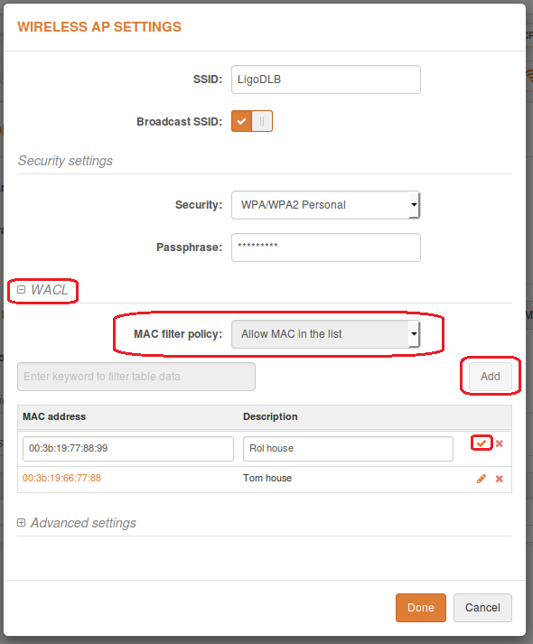
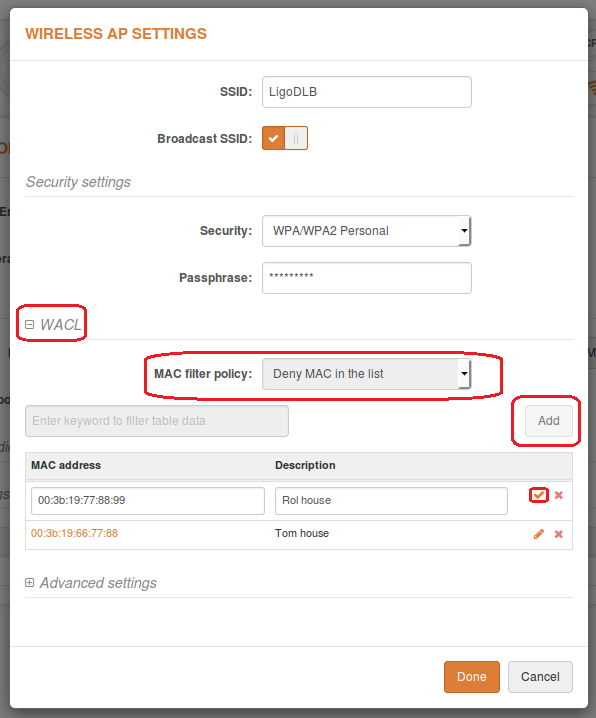
Wireless Access Control List is access control by MAC address (only in AP and iPoll 2 AP wireless modes). Access Control provides the ability to limit associations wirelessly based on MAC address to an AP by creating an Access Control List (ACL).
Wireless Access Control List is based in Wireless AP settings section:
To add new rule press the “Add” button.Open – no rules applied
Enable Allow MAC filter policy – select Allow MAC in the list to enable connect only devices in the list. (White list)
Enable Deny MAC filter policy – select Deny MAC in the list to prohibit connection for devices in the list. (Black list)
Do not forget to click tick to save MAC in list after editing
Настройка Ligowave DLB с управлением в отдельном VLAN
Management and Data VLAN configuration
Virtual Local Area Networks (VLANs) are logical groupings of network resources.
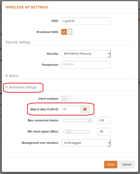
Enable management VLAN – enable a VLAN tagging for management traffic. Access to the AP for management purposes can further be limited using VLAN tagging. By defining Management VLAN, the device will only accept management frames that have the appropriate Management VLAN ID. All other frames using any management protocol will be rejected.
Management VLAN ID – specify the VLAN ID [2-4095]. When device interfaces are configured with a specific VLAN ID value, only management frames that matching configured VLAN ID will be accepted by device.
When you specify a new management VLAN, your HTTP connection to the device will be lost. For this reason, you should have a connection between your management station and a port in the new management VLAN or connect to the new management VLAN through a multi-VLAN routerNetwork management is available only on Bridge network mode
Map to data VLAN ID – specify the VLAN ID for traffic tagging on particular radio interface. The Station devices that associate using the particular SSID will be grouped into this VLAN.
Management over wireless – controls the wireless administrative access. For security reasons, it is recommended disable wireless access and instead requires a physical network connection using an Ethernet cable for administrative access to APC. Depending from management VLAN enabled or not Management over wireless would be according
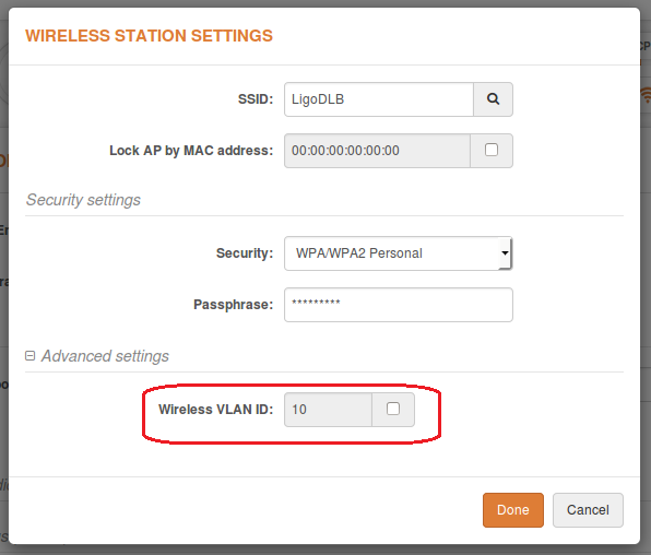
Enable Wireless VLAN ID on the Station to enable data VLAN:
Настройка Ligowave DLB в режиме роутера
Setup CPE as a Router
Step 1. Navigate to the Configuration | Wireless tab, choose Station wireless mode, click Scan button near the SSID entry field to choose the SSID of the AP where the station will be associated to. Specify the Security parameters for the AP, check IEEE mode (these settings must conform with AP wireless settings) and click Save&Apply:
Step 2. Verify connection. Navigate to the Status | Information page. The Information page will display wireless information of the link with access point. The connection status must be displayed as Connected and progress bars indicating the quality of the connection must be displayed:
Router IPv4 Mode
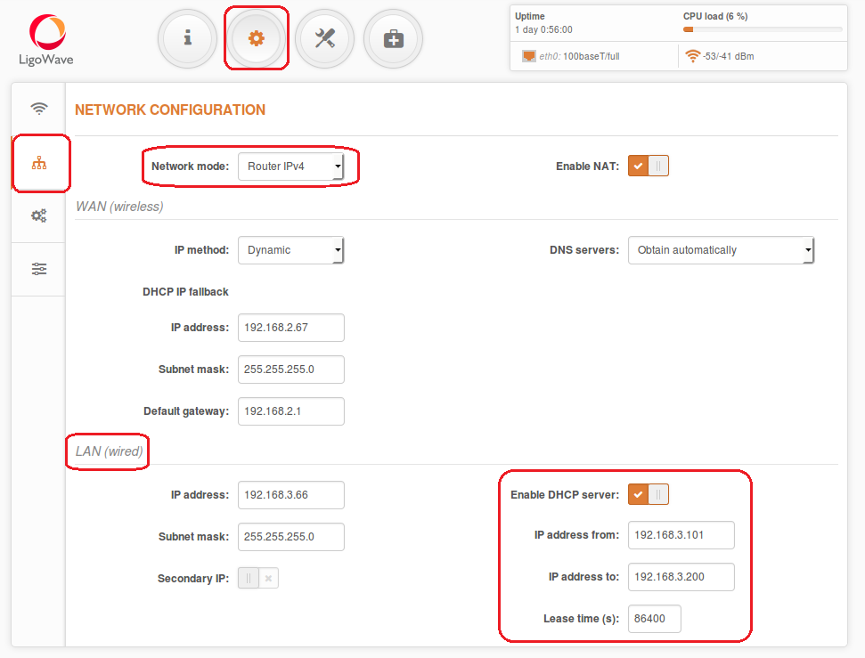
Step 1. This section allows customizing parameters of the Router to suit the needs of network, including ability to use the built-in DHCP server. When device is configured to operate as Router, the following sections should be specified: WAN network settings, LAN network settings and LAN DHCP settings.
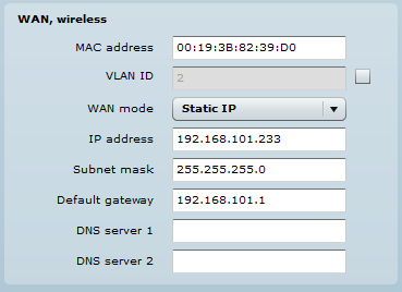
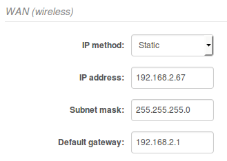
Step 2. WAN Settings WAN network settings include settings related to the WAN interface. In this scenario WAN interface is from wireless side. The access type of the WAN interface can be configured as: Static IP, Dynamic IP. WAN mode – choose Static IP to specify IP settings for device WAN interface:
Set static IP from the same subnet as is AP device. Then you could reach station from your network
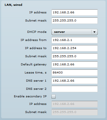
Step 3. DHCP mode – choose server to enable DHCP server on LAN interface.
In IP address field set address with which you could reach device via wired LAN
IP address from – specify the starting IP address of the DHCP address pool.
IP address to – specify the ending IP address of DHCP address pool.
Subnet mask – specify the subnet mask.
Default gateway – specify DHCP gateway IP address.
Lease time – specify the expiration time in seconds for the IP address assigned by the DHCP server.
DNS server – specify the DNS server IP address on the WAN side.
Router IPv6 Mode
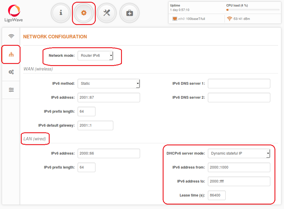
Step 1. To setup IPv6 router, select the Network mode as Router IPv6 and specify the required WAN and LAN settings.
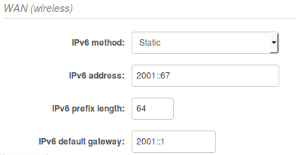
Step 2. WAN Settings WAN network settings include settings related to the WAN interface. In this scenario WAN interface is from wireless side. The access type of the WAN interface can be configured as: Dynamic stateless IPv6, Dynamic stateful IPv6 and Static IPv6. WAN mode – choose Static IPv6 to specify IPv6 settings for device WAN interface:
IPv6 WAN (wired) settings: Static
With this IPv6 method selected, settings must be specified manually
IPv6 WAN (wired) settings: Dynamic Stateless
With Dynamic stateless IPv6, device generates its own IP address by using a combination of locally available information and router advertisements, but receives DNS server information from a DHCPv6 server. The IP address is a dynamic address.
IPv6 WAN (wired) settings: Dynamic Stateful
With Dynamic stateful IP, device obtains an interface address, configuration information such as DNS server information, and other parameters from a DHCPv6 server. The IP address is a dynamic address.
IPv6 address – specify the IPv6 address for the interface Deliberant
IPv6 prefix length– enter the prefix length for the address (default is 64).
IPv6 default gateway – specify IPv6 address for default gateway.
IPv6 DNS server – specify the Domain Naming Server IPv6 addresses.Set static IPv6 from the same subnet as is AP device. Then you could reach station from your network
Step 3. DHCPv6 mode – choose server to enable DHCPv6 server on LAN interface.
In IP address field set address with which you could reach device via wired LAN
Parameters explanation
IPv6 prefix length – specify the IPv6 prefix length, or keep the default prefix length (64).
DHCPv6 server mode – select from the drop-down required DHCPv6 mode:
Disabled – select to disable DHCPv6 server. No IPv6 addresses will be assigned for clients.
Dynamic stateless IP – select for automatic IPv6 address configuration.
Dynamic stateful IP – select to configure stateful DHCPv6 server for the LAN by specifying local DHCP IPv6 address pools so the DHCPv6 server can control the allocation of IPv6 addresses inthe LAN:
IPv6 address from – enter the start IP address. This address specifies the first of the contiguous addresses in the IP address pool.
IPv6 address to – enter the end IP address. This address specifies the last of the contiguous addresses in the IP address pool.
Lease time – specify the expiration time in seconds for the IP address assigned by the DHCPv6 server.
Настройка Ligowave DLB в режиме PPPoE-клиента
How to configure PPPoE client
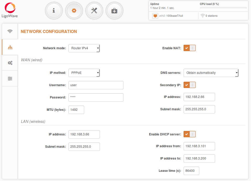
In router mode the DLB APC will receive internet through WAN port and will share it to the LAN ports that will be separated with a different IP range. The type of connection to the WAN interface can be made by Static IP, DHCP client or PPPoE.
WAN mode – choose PPPoE to configure WAN interface to connect to an ISP via a PPPoE.In Access Point mode WAN will be Ethernet side in the Station mode WAN will be Radio interface.
In main configuration should be added Username, Password all other settings should be left by default:
Parameters explanation
PPPoE settings on WAN interface:
User name – specify the user name for PPPoE.
Password – specify the password for PPPoE.
MTU – specify the MTU (Maximum Transmission Unit) in bytes.
Enable secondary IP – specify the alternative IP address and the netmask for LigoDLB unit management.
DNS settings – allows selecting if automatically assigned or alternative DNS servers should be used.
LAN Network Settings:
IP address – specify the IP address of the device LAN interface.
Subnet mask – specify the subnet mask of the device LAN interface.
Enable DHCP server – select to enable DHCP server on LAN interface.
IP address from – specify the starting IP address of the DHCP address pool.
IP address to – specify the ending IP address of DHCP address pool.
Lease time – specify the expiration time in seconds for the IP address assigned by the DHCP
server.
Настройка Ligowave DLB в режиме HotSpot или беспроводного повторителя
By default LigoDLB series do not have hotspot features in the firmware.
To enable UAM or Repeater features, follow these instructions:
1. Download the zip file from LigoWave page either for LigoDLB 2/5 or LigoDLB PRO 2/5 series – which ever you are using now:
- LigoDLB 2 series firmware
- LigoDLB 5 series firmware
- LigoDLB PRO 2 series firmware
- LigoDLB PRO 5 series firmware
2. The zip file contains three files:
- Main firmware
- Default configuration firmware
- ReadME file with upgrade instructions
3. First upgrade the LigoDLB unit with main firmware.
4. Then upgrade the LigoDLB unit with default configuration firmware.
5. Do a reset to defaults.
6. Then follow the instructions for NFT on how to configure hotspot scenarios: How to configure repeater
7. Once configured, do the firmware upgrade second time with main image in order to set the backup image for dual-boot.NFT firmware has only two wireless modes: Access Point and RepeaterHow to revert device from NFT firmware to LigoDLB: Revert device from NFT firmware
Настройка в режиме повторителя
How to configure Repeater
By default LigoDLB series devices do not have Repeater functionality in the firmware.
To enable Repeater, follow these instructions:
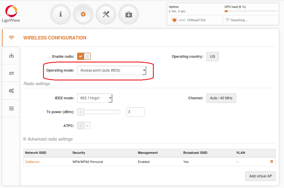
Firstly access point has to be configured as a standard Access point (Auto WDS):
Configure the SSID and Security:
Click on Save and apply to save the settings.
To configure the access point to automatically receive the network settings, set the IP method to Dynamic:
Click on Save and apply to save the settings.
Keep the Access point powered on and either plug the LAN connection to a live network (modem, router, switch) or just unplug from the configuration compute.
Configure Repeater (station settings)
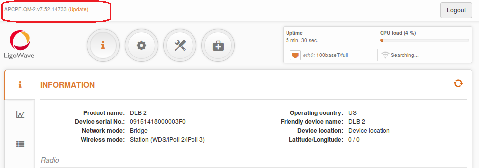
Power on the repeater device and click on the update firmware link on the top left side of the screen
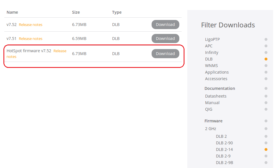
Download and unzip the HotSpot firmware from https://www.ligowave.com/downloads
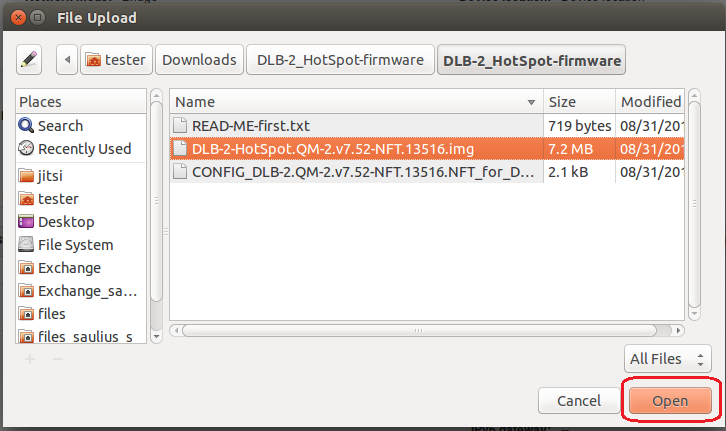
Unzip the LigoDLB HotSpot-firmware. There are two files in this folder. DLB-2/5-HotSpot.QM-2/5.vXX.NFT.img and CONFIG_DLB-2/5.QM-2/5.vXX.NFT. NFT_for_DLB-2/5.OEM.img
Browse to the location of the unzipped DLB-2/5_HotSpot-firmware folder. Select DLB-2/5-HotSpot.QM-2/5.vXX-NFT.img and click Open:
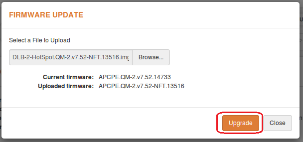
Click on Upload and Upgrade:
Do not interrupt the firmware update.
Click on the update firmware link on the top left side of the screen:
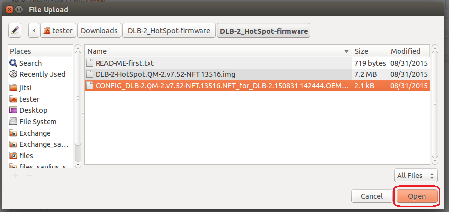
Browse to the location of the unzipped DLB-2/5_HotSpot-firmware folder.
Select CONFIG_DLB-2/5.QM-2/5.vXX-NFT.NFT_for_DLB-2/5.OEM.img and click open:
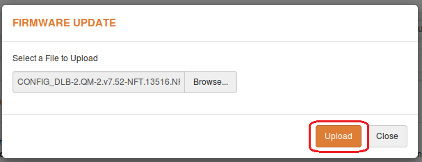
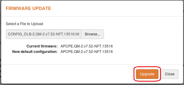
Click on upload:
Click on upgrade:
Once the update is complete, click reset to factory defaults under system settings:
Repeater Configuration
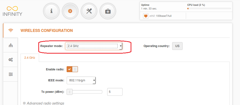
Login and enable repeater mode
Make sure that the access point is powered up.
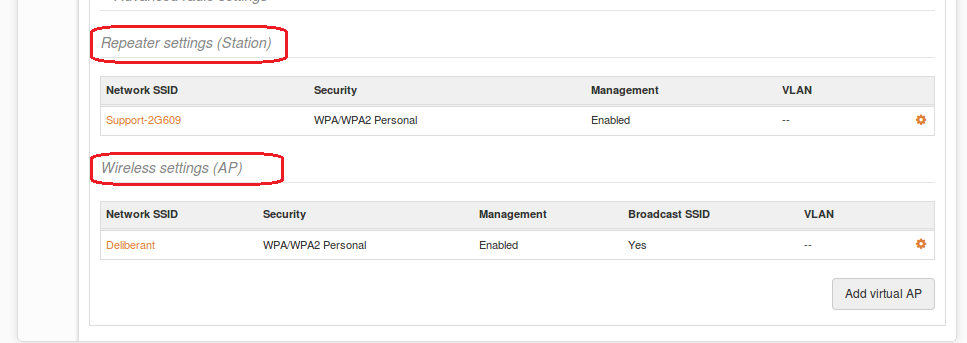
Click on the configuration gear under the Repeater settings (Station):
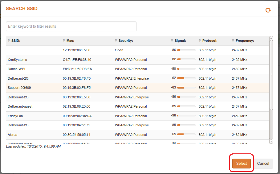
Click on the magnifying glass to search for the access point:
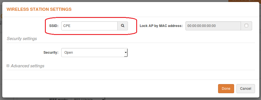
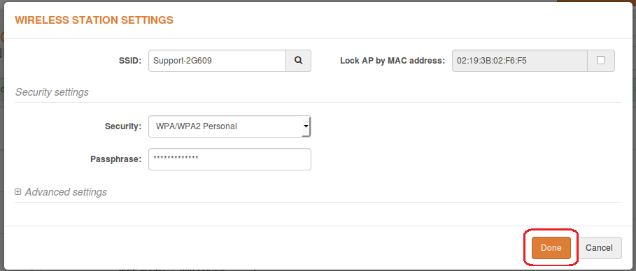
Choose the Access point from the list and select the same security settings as the access point:
When configuration will be finished click done:
Check if Repeater (Station) and Access Point repeater configured correctly:
Remember to always click on Save and apply to make all changes permanent.
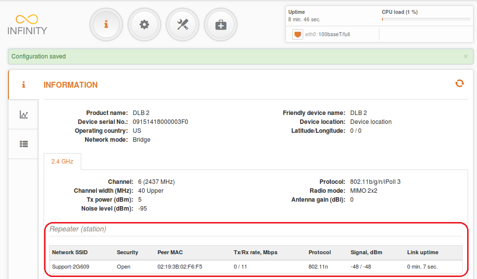
Verify from the access point that the repeater is connected by going to the information/wireless settings:
- Verify devices connected to the repeated SSID by going to information/wireless on the repeater
- The access point and repeater devices are now ready to install
На чтение 32 мин. Просмотров 2.1k.
Содержание
- Настройка Ligowave APC в режиме Point-to-Point (точка-точка)
- Настройка Ligowave APC в режиме Point-to-MultiPoint (точка-многоточка)
- Настройка Ligowave APC в режиме HotSpot
- Настройка Ligowave APC с разделением SSID по VLAN
- Настройка Ligowave APC в режиме беспроводного повторителя (репитера)
- Настройка Ligowave APC ограничение скорости трафика
- Настройка Ligowave APC в режиме роутера
- Настройка Ligowave APC проброс DHCP-сервера (DHCP relay)
- Настройка Ligowave APC PPPoE-клиент
- Настройка Ligowave DLB в режиме моста точка-точка
- Настройка Ligowave DLB в режиме моста точка-многоточка
- Настройка Ligowave DLB с ограничением подключаемых клиентов по MAC-адресу
- Настройка Ligowave DLB с управлением в отдельном VLAN
- Management and Data VLAN configuration
- Настройка Ligowave DLB в режиме роутера
- Setup CPE as a Router
- Router IPv4 Mode
- Router IPv6 Mode
- Parameters explanation
- Настройка Ligowave DLB в режиме PPPoE-клиента
- How to configure PPPoE client
- Parameters explanation
- Настройка Ligowave DLB в режиме HotSpot или беспроводного повторителя
- Настройка в режиме повторителя
Настройка Ligowave APC в режиме Point-to-Point (точка-точка)
It is recommended to use iPoll protocol for simple Point to Point network configuration.
Follow the steps to create a simple Point to Point link between Access Point iPoll and Station (iPoll):
Step 1. Access Point iPoll configuration: change device’s default IP address (can be static or dynamic), enable IP alias if necessary:
Step 2. Configure wireless settings for Access Point iPoll:– Select wireless mode: Access Point iPoll– Define SSID– Set channel: Auto– Enable Security for secure traffic on linkall other settings should be left default:
Step 3. Station iPoll configuration: change device’s default IP address (can be static or dynamic), enable IP alias if necessary:
Step 4. Configure wireless settings for Station iPoll:– Select wireless mode: Station (auto iPoll)– Define SSID, or use “Scan” button to find iPoll Access Points automatically– Enable Security for secure traffic on linkall other settings should be left default: Note that Station iPoll security settings must conform the settings configured on the Access Point iPoll that station is associated with.
Step 5. It is highly recommended to change default administrator’s password for each unit:
Step 6. Verify the PTP link connection. Navigate to the Status | Information page. The Information page will display wireless information of the link.
The status page of the Access Point iPoll must indicate that one peer (Station iPoll) is connected and information about connection must be displayed as follows:
The status of the Station iPoll must be displayed as Connected and progress bars indicating the quality of the connection must be displayed:
Настройка Ligowave APC в режиме Point-to-MultiPoint (точка-многоточка)
Point to Multipoint bridged network configuration
In a bridged (layer 2) network could be used in WDS or ipoll modes. Ipoll mode should be used when AP and all stations are Deliberant products otherwise select WDS mode. Recommended maximum stations per AP can be from 60 to 70.
Configuration
Change device’s IP address (can be static or dynamic), enable IP alias if necessary. Default ip address could be left because it is used for device management.
Access Point Wirelles section configuration steps:
- Select country code
- Select wireless mode: Access point WDS
- Define SSID
- Choose IEEE mode:
- N if you use 802.11n capable radios
- A/N mixed or B/G/N mixed if you also use legacy radios in your network
- Set channel to “Auto”
- Set Max data rate with Auto data rate “Dynamic algorithm”
- Enable Security if necessary
- Set ACK timeout based on the maximum distance from the station
- Leave all other settings as default
Configuration of the stations:Change device’s IP address (can be static or dynamic). Enable IP alias if necessary. All stations ip addresses should be in the same subnet as AP is.
Station Wirelles section configuration steps:-Select country code-Select wireless mode: Station WDS
According to access point:-Define SSID-Choose IEEE mode-Set Max data rate N to “Auto”-Enable Security if necessary-Set ACK timeout based on max distance from the station-Leave all other settings as default
Observe signal levels at Access point and at Station. Recommended signal level range is from -35 to -60 dBm.If the device is MIMO, there are two signal streams. One of them is called as “Main” (Antenna 1), another is “Aux”
Main stream is mandatory. If main signal is very weak, the link will not be stable or will not work at all. It is necessary, to align the antennas for the best main signal. If Aux stream is weak, the link will work at lower data rate. Check if SNR is good on AP and Station and it is over 20/20.AP Point:
Station:
Настройка Ligowave APC в режиме HotSpot
The HotSpot scenario is popular in the various public places like an airport, shop, bar or stadium. The APC allows user authentication through external or internal Web portal. This authentication method is called UAM. User provides login credentials and then Web portal attempts to authenticate and authorize the client using the provided information. Client will not send any authentication requests directly to the APC, the Web portal will do this. On success, APC will allow access to the Internet; otherwise Web portal will display failure notice.
Follow the steps to configure a Hotspot UAM authentication through external Web portal, for wireless clients.
Step 1. Configure network settings: the HotSpot with UAM authentication is available only if APC operates as Router.
Step 2. Setup wireless settings for HotSpot:– Select wireless mode: Access Point (auto WDS)– Define SSID– Set channel: Auto– Choose wireless security: UAM
Step 3. Setup UAM authentication with External web/login page (hosted on separate web server):-Add at least one RADIUS server settings: IP addres, RADIUS secret, authentication and accounting ports
-Setup the External UAM fields: login page URL, welcome page URL, blacklist URL and logout URL
-UAM configuration can be automatically updated from the server at scheduled time
-UAM supports Hotspot description according to WISPr 1.0 recommendation: WISPr location name, operator name, network name, ISO country code, E.164 country code, E.164 area code
-UAM supports traffic limitation and has fields for default bandwidth definition. These parameters/attributes can be overridden per user from the RADIUS.
Step 4. Additionally the following settings can be configured for the UAM autrhentication:-WPA-PSK encryption can be used on UAM for a stronger security-UAM supports white/black list which can be configured statically on the device or can be updated automatically from the server-UAM has an option for AP monitoring through HTTP URL
Step 5. After the UAM authentication is successfully configured on the APC, all wireless clients will be redirected to the External Web portal for authentication.
Настройка Ligowave APC с разделением SSID по VLAN
Virtual AP
Virtual AP functionality is available only in Access Point (auto WDS) wireless mode.
Use the Configuration | Virtual AP page to configure to create up to 7 additional Virtual AP interfaces. The Virtual AP defines a logical wireless network, and the APC can be configured to provide additional 7 wireless networks on each device radio. All the VAPs may be active at the same time meaning that client devices can associate to the APC using any of the VAP SSID.
The Virtual AP table displays a summary of all virtual radio interfaces running on the APC:
To create a new Virtual AP, click on + button to add new entry on the VAP table, then select this entry and specify required parameters:
SSID – specify the unique name for the VAP [string].
Broadcast SSID – when this option is selected the particular SSID is visible during network scans on a wireless station. When unselected, the VAP SSID is not visible and not broadcasted to wireless stations.
Quality of service (WMM) – enable to support quality of service for prioritizing traffic.
Client isolation – enable the user Layer 2 isolation. The Layer 2 isolation blocks the wireless clients from communicating with each other.
Max clients limit – specify the maximum number of associated wireless clients per VAP.
Each VAP security is configured by default as an “open system”, which broadcasts a beacon signal including the configured SSID. For more secure network choose one of the security mechanisms for each VAP interface.
Security – choose the wireless security and encryption method from the drop-down list.Wireless clients must be able to respond with a specific security configuration
VLAN to SSID mapping
Virtual Local Area Networks (VLANs) are logical groupings of network resources.
VLAN to SSID mapping – specify the VLAN ID for traffic tagging on required radio interface [2-4095]. The Station devices that associate using the particular SSID will be grouped into this VLAN. Configuration window is in Configuration/Network section. When device interfaces are configured with a specific VLAN ID value in Management section, only management frames that matching configured VLAN ID will be accepted by device. Restrict management is used when stations have to be management via VLAN too.
Network management is available only on Bridge network modeFor IP eth0 is mandatory because it is interface to the networkWhen you specify a new management VLAN, your HTTP connection to the device will be lost. For this reason, you should have a connection between your management station and a port in the new management VLAN or connect to the new management VLAN through a multi-VLAN router
Настройка Ligowave APC в режиме беспроводного повторителя (репитера)
Use Access Point Repeater mode in order to extend the range of the existing network infrastructure. The Access Point repeater’s wireless settings has possibility to scan SSID of the surrounding APs and choose the required one. Enable WDS when the main AP is working in WDS mode too. Do not forget to add security information which is needed to connect to main AP. Also country code should be the same on all devices.
Repeater Basic Wireless Settings
SSID – specify the SSID of the remote access point.
Enable/Disable WDS – specifies Access Point Repeater mode WDS or non WDS
Scan – click this button to scan for surrounding wireless networks. Found network SSID’s will be available in drop down menu.
Peer Access Point MAC address – enter the MAC address of the remote access point.
Broadcast SSID – enable or disable the broadcasting of the SSID.
IEEE mode – specify the operating wireless mode.
Channel width – The default channel bandwidth for 802.11 radio is 20MHz. The 802.11n allow channel bonding in such way the total channel width becomes 40MHz.
1. Set wireless mode to Access Point Repeater and go into Peer AP settings
2. Scan and choose AP SSID which is going to be repeated.
Both sides (AP and Repeater Peer) of the link must have the same security settings.
3. In Basic and Security sections there could be added the same as main AP SSID and Security information or created new one.
WDS mode should be disabled when main AP is working in regular non WDS mode. Commonly used when trying to repeat simple wireless router.
Настройка Ligowave APC ограничение скорости трафика
Traffic Limiting
Use Traffic Shaping to control download or upload bandwidth in order to optimize or guarantee performance. There are two methods to control network traffic:
Limit all traffic – limits overall APC upload and download traffic.
Limit per IP traffic – limits upload and download traffic for a specified IP addresses.
Limit all traffic
Enable download shaping – select to enable limitation of the download traffic.
Download limit, kbps – specify the maximum download bandwidth value in Kbps.
Download burst, kbytes – specify the download burst size in kbytes.
Enable upload shaping – select to enable limitation of the upload traffic.
Upload limit, kbps – specify the maximum upload bandwidth value in Kbps.
Upload burst, kbytes – specify the upload burst size in kbytes
Limit per IP traffic
Use + button to create new traffic limitation rules:
IP address – specify IP address for which the traffic will be limited.
Down rate, kbps – specify the maximum download bandwidth value in Kbps.
Down burst, kbytes – specify the download burst size in kbytes.
UP rate, kbps – specify the maximum upload bandwidth value in Kbps.
UP burst, kbytes – specify the download burst size in kbytes
Настройка Ligowave APC в режиме роутера
Setup CPE as a Router
Step 1. Navigate to the Configuration | Wireless tab, choose Station wireless mode, click Scan button near the SSID entry field to choose the SSID of the AP where the station will be associated to. Specify the Security parameters for the AP, check IEEE mode (these settings must conform with AP wireless settings) and click Save&Apply:
Step 2. Verify connection. Navigate to the Status | Information page. The Information page will display wireless information of the link with access point. The connection status must be displayed as Connected and progress bars indicating the quality of the connection must be displayed:
Step 3. Router Mode. This section allows customizing parameters of the Router to suit the needs of network, including ability to use the built-in DHCP server. When device is configured to operate as Router, the following sections should be specified: WAN network settings, LAN network settings and LAN DHCP settings.
Step 4. WAN Settings WAN network settings include settings related to the WAN interface. In this scenario WAN interface is from wireless side. The access type of the WAN interface can be configured as: Static IP, Dynamic IP, PPPoE client. WAN mode – choose Static IP to specify IP settings for device WAN interface:Set static IP from the same subnet as is AP device. Then you could reach station from your netwrok
Step 4. DHCP mode – choose server to enable DHCP server on LAN interface.In IP address field set address with which you could reach device via wired LAN
IP address from – specify the starting IP address of the DHCP address pool.
IP address to – specify the ending IP address of DHCP address pool.
Subnet mask – specify the subnet mask.
Default gateway – specify DHCP gateway IP address.
Lease time – specify the expiration time in seconds for the IP address assigned by the DHCP server.
DNS server – specify the DNS server IP address.
Настройка Ligowave APC проброс DHCP-сервера (DHCP relay)
DHCP Relay configuration example
What is DHCP relay mode? The DHCP relay forwards DHCP messages between subnets with different sublayer broadcast domains.
Step 1. Configure AP as bridge with IP 192.168.11.66 netmask 24, GW 192.168.11.1
Step 2. Configure CPE as a Router and connect It to AP. Setup DHCP mode as relay. Static WAN, wireless IP address is from the same subnet as AP which lets to reach device via wireless. LAN, wired IP address is used to reach device from LAN side and should be from the DHCP server subnet.
How to test on Linux
DHCP relay link configuration could be tested in various ways what is needed are DHCP server, router
Step 1. Install DHCP server on your linux pc:
sudo apt-get install isc-dhcp-server
Step 2. Configure DHCP server as following:
Step 3. Step four: configured DHCP server with IP on eth2 interface. IP on eth2: 192.168.11.1 netmask 24, GW 192.168.11.1
Step 4. Step six. Add static route on DHCP server in order to reach x.2.0 LAN with “sudo route add –net 192.168.2.0 netmask 255.255.255.0 gw 192.168.11.1
Step 5. Test the configuration.
Настройка Ligowave APC PPPoE-клиент
How to configure PPPoE client
In router mode the DLB APC will receive internet through WAN port and will share it to the LAN ports that will be separated with a different IP range. The type of connection to the WAN interface can be made by Static IP, DHCP client or PPPoE.
WAN mode – choose PPPoE to configure WAN interface to connect to an ISP via a PPPoE. In main configuration should be added Username, Password all other settings should be left by default:
Parameters explanaition:
MAC address – specify the clone MAC address if required. The ISPs registers the MAC address of the router, and allows only that MAC address to connect to their network. In such case if there is need to change hardware (router), you need to notify your ISP about MAC address change, or simply set the router’s MAC address to the MAC address of the previously router/computer.
VLAN ID – specify the VLAN ID for traffic tagging on required radio interface [2-4095]. The Station devices that associate using the particular SSID will be grouped into this VLAN.
User name – specify the user name for PPPoE.
Password – specify the password for PPPoE.
MTU – specify the MTU (Maximum Transmission Unit). The default value is 1500 bytes.
Reconnect mode – specify PPPoE reconnection mode:
- Always on – PPPoE connection automatically starts without timeout. The router will keep trying to bring up the connection if it is disconnected for some reason.
- On demand – the PPPoE connection automatically starts when there is outbound traffic to the Internet, and it automatically terminates if the connection is idle based on the value specified in the Idle time [1-65535] setting.
DNS settings – allows selecting if automatically assigned or alternative DNS servers should be used.
Enable IP alias – specify the alternative IP address and the netmask for APC unit management.
Настройка Ligowave DLB в режиме моста точка-точка
It is recommended to use iPoll 2 protocol for simple Point to Point network configuration.
Follow the steps to create a simple Point to Point link between Access Point iPoll2 and Station (WDS/iPoll2):
Step 1. Access Point iPoll 2 configuration: change device’s default IP address (can be static or dynamic), enable IP alias (Secondary IP) if necessary:
Step 2. Configure wireless settings for Access Point iPoll 2:– Select wireless mode: Access Point iPoll– Set channel: Autoall other settings should be left default:
Enter the following button in Wireless settings (AP) section to change SSID and Encryption configuration
– Define SSID– Enable Security for secure traffic on link all other settings should be left default:
Step 3.Station iPoll 2 configuration: change device’s default IP address (can be static or dynamic), enable IP alias (Secondary IP) if necessary:
Step 4. Configure wireless settings for Station iPoll 2:– Select wireless mode: Station (WDS/iPoll 2)all other settings should be left default:
Enter the following button in Wireless settings (station) section to change SSID and Encryption configuration
– Define SSID, or use “Scan” button to find iPoll 2 Access Points automatically– Enable Security for secure traffic on link all other settings should be left default:
Note that Station iPoll 2 security settings must conform the settings configured on the Access Point iPoll 2 that station is associated with. Step 5. It is highly recommended to change default administrator’s password for each unit:
Step 6. Verify the PTP link connection. Navigate to the Status | Information page. The Information page will display wireless information of the link.
The status page of the Access Point iPoll 2 must indicate that one peer (Station iPoll 2) is connected and information about connection must be displayed as follows:
Detailed information about connected peers stays at Status | Wireless page.
The status of the Station iPoll 2 must be displayed as Connected and progress bars indicating the quality of the connection must be displayed:
Настройка Ligowave DLB в режиме моста точка-многоточка
Point to Multipoint bridged network configuration
In a bridged (layer 2) network could be used in WDS or ipoll 2 modes. Ipoll 2 mode should be used when AP and all stations are Deliberant products otherwise select WDS mode. Recommended maximum stations per AP can be from 60 to 70.
WDS mode Configuration
Change device’s IP address (can be static or dynamic), enable IP alias (Secondary IP) if necessary. Default ip address could be left because it is used for device management. Configure wireless settings for 11N AP:– Select wireless mode: Access point (auto WDS)
– Choose IEEE mode:
N if you use 802.11n capable radios
A/N mixed or B/G/N mixed if you also use legacy radios in your network
– Set channel to “Auto”
– Set ACK timeout based on the maximum distance from the station, using the slide:
– Define SSID
– Enable Security if necessary
iPoll 2 mode Configuration
Configure wireless settings for iPoll 2 master:– Select wireless mode: Access Point iPoll– Define SSID– Set channel to “Auto”– Enable Security if necessaryall other settings should be kept default:
Configuration of the stations:Change device’s IP address (can be static or dynamic). Enable IP alias (Secondary IP) if necessary. All stations ip addresses should be in the same subnet as AP is.
Change second device’s IP address (can be static or dynamic). Enable IP alias (Secondary IP) if necessary.
Station- Wireless section configuration steps:
According to access point:
-Select country code
-Select wireless mode: Station (WDS/iPoll 2)-Set Max data rate N to “Auto”-Set ACK timeout based on max distance from the station-Leave all other settings as default
-Enable Security if necessary-Define SSID
Observe with indicator at Access point that all Stations are connected.
Observe signal levels at Access point and at Station. Recommended signal level range is from -35 to -60 dBm.
If the device is MIMO, there are two signal streams. One of them is called as “Main” (Antenna 1), another is “Aux”Main stream is mandatory. If main signal is very weak, the link will not be stable or will not work at all. It is necessary, to align the antennas for the best main signal. If Aux stream is weak, the link will work at lower data rate. Check if CCQ is good on AP and Station and it is approaching to 100/100.
Step 6. For the best performance, optimize the channel size. Before changing auto channel to some particular channel it is recommended to do the scan on AP and on Station (Tools|Site survey). Try to find the clearest frequency for device operation.
Настройка Ligowave DLB с ограничением подключаемых клиентов по MAC-адресу
Wireless Access Control List is access control by MAC address (only in AP and iPoll 2 AP wireless modes). Access Control provides the ability to limit associations wirelessly based on MAC address to an AP by creating an Access Control List (ACL).
Wireless Access Control List is based in Wireless AP settings section:
To add new rule press the “Add” button.Open – no rules applied
Enable Allow MAC filter policy – select Allow MAC in the list to enable connect only devices in the list. (White list)
Enable Deny MAC filter policy – select Deny MAC in the list to prohibit connection for devices in the list. (Black list)
Do not forget to click tick to save MAC in list after editing
Настройка Ligowave DLB с управлением в отдельном VLAN
Management and Data VLAN configuration
Virtual Local Area Networks (VLANs) are logical groupings of network resources.
Enable management VLAN – enable a VLAN tagging for management traffic. Access to the AP for management purposes can further be limited using VLAN tagging. By defining Management VLAN, the device will only accept management frames that have the appropriate Management VLAN ID. All other frames using any management protocol will be rejected.
Management VLAN ID – specify the VLAN ID [2-4095]. When device interfaces are configured with a specific VLAN ID value, only management frames that matching configured VLAN ID will be accepted by device.
When you specify a new management VLAN, your HTTP connection to the device will be lost. For this reason, you should have a connection between your management station and a port in the new management VLAN or connect to the new management VLAN through a multi-VLAN routerNetwork management is available only on Bridge network mode
Map to data VLAN ID – specify the VLAN ID for traffic tagging on particular radio interface. The Station devices that associate using the particular SSID will be grouped into this VLAN.
Management over wireless – controls the wireless administrative access. For security reasons, it is recommended disable wireless access and instead requires a physical network connection using an Ethernet cable for administrative access to APC. Depending from management VLAN enabled or not Management over wireless would be according
Enable Wireless VLAN ID on the Station to enable data VLAN:
Настройка Ligowave DLB в режиме роутера
Setup CPE as a Router
Step 1. Navigate to the Configuration | Wireless tab, choose Station wireless mode, click Scan button near the SSID entry field to choose the SSID of the AP where the station will be associated to. Specify the Security parameters for the AP, check IEEE mode (these settings must conform with AP wireless settings) and click Save&Apply:
Step 2. Verify connection. Navigate to the Status | Information page. The Information page will display wireless information of the link with access point. The connection status must be displayed as Connected and progress bars indicating the quality of the connection must be displayed:
Router IPv4 Mode
Step 1. This section allows customizing parameters of the Router to suit the needs of network, including ability to use the built-in DHCP server. When device is configured to operate as Router, the following sections should be specified: WAN network settings, LAN network settings and LAN DHCP settings.
Step 2. WAN Settings WAN network settings include settings related to the WAN interface. In this scenario WAN interface is from wireless side. The access type of the WAN interface can be configured as: Static IP, Dynamic IP. WAN mode – choose Static IP to specify IP settings for device WAN interface:
Set static IP from the same subnet as is AP device. Then you could reach station from your network
Step 3. DHCP mode – choose server to enable DHCP server on LAN interface.
In IP address field set address with which you could reach device via wired LAN
IP address from – specify the starting IP address of the DHCP address pool.
IP address to – specify the ending IP address of DHCP address pool.
Subnet mask – specify the subnet mask.
Default gateway – specify DHCP gateway IP address.
Lease time – specify the expiration time in seconds for the IP address assigned by the DHCP server.
DNS server – specify the DNS server IP address on the WAN side.
Router IPv6 Mode
Step 1. To setup IPv6 router, select the Network mode as Router IPv6 and specify the required WAN and LAN settings.
Step 2. WAN Settings WAN network settings include settings related to the WAN interface. In this scenario WAN interface is from wireless side. The access type of the WAN interface can be configured as: Dynamic stateless IPv6, Dynamic stateful IPv6 and Static IPv6. WAN mode – choose Static IPv6 to specify IPv6 settings for device WAN interface:
IPv6 WAN (wired) settings: Static
With this IPv6 method selected, settings must be specified manually
IPv6 WAN (wired) settings: Dynamic Stateless
With Dynamic stateless IPv6, device generates its own IP address by using a combination of locally available information and router advertisements, but receives DNS server information from a DHCPv6 server. The IP address is a dynamic address.
IPv6 WAN (wired) settings: Dynamic Stateful
With Dynamic stateful IP, device obtains an interface address, configuration information such as DNS server information, and other parameters from a DHCPv6 server. The IP address is a dynamic address.
IPv6 address – specify the IPv6 address for the interface Deliberant
IPv6 prefix length– enter the prefix length for the address (default is 64).
IPv6 default gateway – specify IPv6 address for default gateway.
IPv6 DNS server – specify the Domain Naming Server IPv6 addresses.Set static IPv6 from the same subnet as is AP device. Then you could reach station from your network
Step 3. DHCPv6 mode – choose server to enable DHCPv6 server on LAN interface.
In IP address field set address with which you could reach device via wired LAN
Parameters explanation
IPv6 prefix length – specify the IPv6 prefix length, or keep the default prefix length (64).
DHCPv6 server mode – select from the drop-down required DHCPv6 mode:
Disabled – select to disable DHCPv6 server. No IPv6 addresses will be assigned for clients.
Dynamic stateless IP – select for automatic IPv6 address configuration.
Dynamic stateful IP – select to configure stateful DHCPv6 server for the LAN by specifying local DHCP IPv6 address pools so the DHCPv6 server can control the allocation of IPv6 addresses inthe LAN:
IPv6 address from – enter the start IP address. This address specifies the first of the contiguous addresses in the IP address pool.
IPv6 address to – enter the end IP address. This address specifies the last of the contiguous addresses in the IP address pool.
Lease time – specify the expiration time in seconds for the IP address assigned by the DHCPv6 server.
Настройка Ligowave DLB в режиме PPPoE-клиента
How to configure PPPoE client
In router mode the DLB APC will receive internet through WAN port and will share it to the LAN ports that will be separated with a different IP range. The type of connection to the WAN interface can be made by Static IP, DHCP client or PPPoE.
WAN mode – choose PPPoE to configure WAN interface to connect to an ISP via a PPPoE.In Access Point mode WAN will be Ethernet side in the Station mode WAN will be Radio interface.
In main configuration should be added Username, Password all other settings should be left by default:
Parameters explanation
PPPoE settings on WAN interface:
User name – specify the user name for PPPoE.
Password – specify the password for PPPoE.
MTU – specify the MTU (Maximum Transmission Unit) in bytes.
Enable secondary IP – specify the alternative IP address and the netmask for LigoDLB unit management.
DNS settings – allows selecting if automatically assigned or alternative DNS servers should be used.
LAN Network Settings:
IP address – specify the IP address of the device LAN interface.
Subnet mask – specify the subnet mask of the device LAN interface.
Enable DHCP server – select to enable DHCP server on LAN interface.
IP address from – specify the starting IP address of the DHCP address pool.
IP address to – specify the ending IP address of DHCP address pool.
Lease time – specify the expiration time in seconds for the IP address assigned by the DHCP
server.
Настройка Ligowave DLB в режиме HotSpot или беспроводного повторителя
By default LigoDLB series do not have hotspot features in the firmware.
To enable UAM or Repeater features, follow these instructions:
1. Download the zip file from LigoWave page either for LigoDLB 2/5 or LigoDLB PRO 2/5 series – which ever you are using now:
- LigoDLB 2 series firmware
- LigoDLB 5 series firmware
- LigoDLB PRO 2 series firmware
- LigoDLB PRO 5 series firmware
2. The zip file contains three files:
- Main firmware
- Default configuration firmware
- ReadME file with upgrade instructions
3. First upgrade the LigoDLB unit with main firmware.
4. Then upgrade the LigoDLB unit with default configuration firmware.
5. Do a reset to defaults.
6. Then follow the instructions for NFT on how to configure hotspot scenarios: How to configure repeater
7. Once configured, do the firmware upgrade second time with main image in order to set the backup image for dual-boot.NFT firmware has only two wireless modes: Access Point and RepeaterHow to revert device from NFT firmware to LigoDLB: Revert device from NFT firmware
Настройка в режиме повторителя
How to configure Repeater
By default LigoDLB series devices do not have Repeater functionality in the firmware.
To enable Repeater, follow these instructions:
Firstly access point has to be configured as a standard Access point (Auto WDS):
Configure the SSID and Security:
Click on Save and apply to save the settings.
To configure the access point to automatically receive the network settings, set the IP method to Dynamic:
Click on Save and apply to save the settings.
Keep the Access point powered on and either plug the LAN connection to a live network (modem, router, switch) or just unplug from the configuration compute.
Configure Repeater (station settings)
Power on the repeater device and click on the update firmware link on the top left side of the screen
Download and unzip the HotSpot firmware from https://www.ligowave.com/downloads
Unzip the LigoDLB HotSpot-firmware. There are two files in this folder. DLB-2/5-HotSpot.QM-2/5.vXX.NFT.img and CONFIG_DLB-2/5.QM-2/5.vXX.NFT. NFT_for_DLB-2/5.OEM.img
Browse to the location of the unzipped DLB-2/5_HotSpot-firmware folder. Select DLB-2/5-HotSpot.QM-2/5.vXX-NFT.img and click Open:
Click on Upload and Upgrade:
Do not interrupt the firmware update.
Click on the update firmware link on the top left side of the screen:
Browse to the location of the unzipped DLB-2/5_HotSpot-firmware folder.
Select CONFIG_DLB-2/5.QM-2/5.vXX-NFT.NFT_for_DLB-2/5.OEM.img and click open:
Click on upload:
Click on upgrade:
Once the update is complete, click reset to factory defaults under system settings:
Repeater Configuration
Login and enable repeater mode
Make sure that the access point is powered up.
Click on the configuration gear under the Repeater settings (Station):
Click on the magnifying glass to search for the access point:
Choose the Access point from the list and select the same security settings as the access point:
When configuration will be finished click done:
Check if Repeater (Station) and Access Point repeater configured correctly:
Remember to always click on Save and apply to make all changes permanent.
Verify from the access point that the repeater is connected by going to the information/wireless settings:
- Verify devices connected to the repeated SSID by going to information/wireless on the repeater
- The access point and repeater devices are now ready to install
Описание LigoWave LigoDLB 2-9 (DLB-2-9)
LigoWave LigoDLB 2-9 (DLB-2-9) Универсальное, стабильное и эффективное устройство (с высокой выходной мощностью до 28 дБм) работает на частоте 2.4 ГГц, а также поддерживает стандарт 802.11n и технологию MIMO 2×2. Надёжный, качественный и небольшой по форм-фактору корпус в сочетании с направленной панельной антенной (9 дБи) — то, что нужно для работы на коротких и дальних расстояниях.
Встроенная поддержка фирменного протокола iPoll 3 обеспечивает надёжную связь даже в густонаселённых районах (до 64-х устройств, подключённых к базовой станции).
Фирменная технология хранения резервного образа прошивки позволяет безопасно обновлять программное обеспечение устройства, не боясь отключения электроэнергии при этом процессе. В случае неудачного обновления прошивки устройство будет автоматически перезагружено с использованием резервной копии прошивки.
Корпус изготовлен из поликарбонатного пластика с УФ-ингибитором, что гарантирует долгосрочность наружного использования устройства под воздействием прямых солнечных лучей без риска поломки. LigoDLB 2-9 был протестирован на вибрацию, температуру, перепады, соль, туман и соответствием стандартам электрического перенапряжения, чтобы гарантировать высокий уровень надёжности устройства. Оснащён заземляющим наконечником и заземлённым PoE 24 В для профессионального монтажа и устойчивости к электрическим разрядам.
Новая аппаратная платформа
Высокопроизводительный мощный процессор нового поколения обеспечивает скорость передачи данных до 170 Мбит/с, а обработки пакетов — до 80 000 пак/с. Поддержка узких каналов (ширина канала 5 и 10 МГц) гарантирует устойчивую работу в условиях зашумлённого эфира. Увеличенный объём ОЗУ повышает производительность при немалом количестве клиентов, а больший объём ПЗУ позволяет хранить запасной дополнительный образ прошивки для автоматического восстановления.
Встроенная защита от перенапряжения
Защита от электростатического разряда (3 кВ линия-земля и 1 кВ линия-линия) позволяет устройству работать в суровых погодных условиях и нестабильных электрических инсталляциях.
Новая ОС
Новая операционная система включает в себя все функции, необходимые для построения сетей точка-многоточка. Отзывчивый пользовательский интерфейс, построенный на основе технологии HTML 5. Среди новых функций стоит отметить поддержку IPv6 в режимах bridge и router, протоколов обнаружения SSDP и Bonjour, гибкую систему ограничения скорости трафика и клиент SSTP. Новое поколение устройств (линейка LigoDLB) обладает обратной совместимостью с устройствами линейки APC фирмы Deliberant, в том числе в части использования проприетарного протокола iPoll — для работы просто обновите прошивку на устройствах (до версии 7.0 и выше).
iPoll 3 — улучшенный производительный протокол
Собственный протокол — это инновационное решение для устранения задержек и помех при передаче данных в беспроводных PtMP-установках.
Особенности LigoWave LigoDLB 2-9 (DLB-2-9)
- Поддержка диапазона 2.402–2.492 ГГц
- Высокая выходная мощность: 28 дБм
- Встроенная направленная панельная антенна с усилением 9 дБи
- Мощная операционная система
- Возможность крепления на мачту
Характеристики радиочасти
| Выходная мощность (дБм) | |||||
| 802.11g | 802.11n/iPoll (20/40 МГц) | ||||
| 6 Мбит/c | 28 | 15 Мбит/c | 28 | 30 Мбит/c | 28 |
| 9 Мбит/c | 28 | 30 Мбит/c | 28 | 60 Мбит/c | 28 |
| 12 Мбит/c | 28 | 45 Мбит/c | 28 | 90 Мбит/c | 28 |
| 18 Мбит/c | 28 | 60 Мбит/c | 28 | 120 Мбит/c | 28 |
| 24 Мбит/c | 28 | 90 Мбит/c | 28 | 180 Мбит/c | 28 |
| 36 Мбит/c | 27 | 120 Мбит/c | 27 | 240 Мбит/c | 26 |
| 48 Мбит/c | 26 | 135 Мбит/c | 25 | 270 Мбит/c | 24 |
| 54 Мбит/c | 25 | 150 Мбит/c | 24 | 300 Мбит/c | 23 |
| Чувствительность приёмника (дБм) | |||||
| 802.11g | 802.11n/iPoll (20/40 МГц) | ||||
| 6 Мбит/c | -95 | 15 Мбит/c | -91 | 30 Мбит/c | -91 |
| 9 Мбит/c | -94 | 30 Мбит/c | -91 | 60 Мбит/c | -91 |
| 12 Мбит/c | -93 | 45 Мбит/c | -89 | 90 Мбит/c | -89 |
| 18 Мбит/c | -90 | 60 Мбит/c | -88 | 120 Мбит/c | -88 |
| 24 Мбит/c | -88 | 90 Мбит/c | -86 | 180 Мбит/c | -86 |
| 36 Мбит/c | -86 | 120 Мбит/c | -82 | 240 Мбит/c | -82 |
| 48 Мбит/c | -82 | 135 Мбит/c | -78 | 270 Мбит/c | -78 |
| 54 Мбит/c | -81 | 150 Мбит/c | -76 | 300 Мбит/c | -76 |
Технические характеристики
| ОСНОВНЫЕ ХАРАКТЕРИСТИКИ | |
| Рекомендуемая максимальная дальность | В режиме PTMP — 3 кмВ режиме PTP — 5 кмПри максимальной скорости в режиме PTP — 2 км |
| Беспроводной стандарт | IEEE 802.11b/g/n, iPoll (проприетарный) |
| Защита от перенапряжения | 3 кВ линия-земля, 1 кВ линия-линия |
| Поддержка MIMO | Да, 2×2 |
| Диапазон частот | 2.402–2.492 ГГц |
| Мощность передатчика | До 20 дБм для РФ (до 28 дБм для других стран) |
| Чуствительность приёмника | От -95 до -76 дБм в зависимости от модуляции |
| Ширина канала | 5, 10, 20, 40 МГц |
| Схемы модуляции | 802.11 g/n: OFDM (64-QAM, 16-QAM, QPSK, BPSK)802.11 b: DSS (CCK, DQPSK, DBPSK) |
| Скорости передачи данных | 802.11 n: 300, 270, 240, 180, 120, 90, 60, 30 Mbps802.11 g: 54, 48, 36, 24, 18, 12, 9, 6 Mbps802.11 b: 11, 5.5, 2, 1 Mbps |
| Коррекция ошибок | FEC, Selective ARQ |
| Схема дуплексирования | Time division duplex |
| Тип антенны | Встроенная панельная направленная |
| Усиление антенны | 9 дБи |
| Поляризация | Двойная линейная |
| Угол излучения в горизонтальной плоскости при горизонтальной поляризации | 60° |
| Угол излучения в горизонтальной плоскости при вертикальной поляризации | 60° |
| Угол излучения в вертикальной плоскости | 60° |
| КСВН | |
| Кросс-поляризационная развязка | 23 дБи |
| Проводной интерфейс | 1х 10/100 Base-T, RJ45 |
| Режимы работы | Точка доступа (Auto WDS), точка доступа iPoll 3, клиент (WDS, iPoll3), клиент (APR NAT) |
| Расширенная беспроводная функциональность | ATPC (автоматический контроль мощности передатчика), автоканал, автомодуляция, опрос клиентов по интеллектуальному методу |
| Беспроводная безопасность | WPA / WPA2 Personal, WPA / WPA2 Enterprise, WACL, изоляция пользователей |
| Беспроводной QoS | Приоритизация с 4 очередями |
| Сетевые режимы | Bridge, router iPv4, router IPv6 |
| Сетевые функции | Маршрутизация с и без NAT, VLAN, Firewall* |
| WAN | Static IP, DHCP client, PPPoE client |
| Сервисы | DHCP server, SNMP server, NTP client, RADVD, Ping Watchdog |
| Управление | HTTP(S) веб-интерфейс, SSH, чтение SNMP, WNMS, Telnet |
| Инструменты | Радиообследование объекта, тест канала, выравнивание антенны |
| Диаметр мачты | 35–60 мм (диаметры мачт для крепления устройств LigoWave) |
| Питание | 12–24 В DC, Passive PoE (100–240 В AC 18 В DC адаптер в комплекте) |
| Максимальная потребляемая энергия | 6 Вт |
| Температура окружающей среды рабочая | -40.. +65 °С |
| Влажность окружающей среды рабочая | 0.. 90% без конденсации |
| Мониторинг системы | SNMP v1/2c/3 server, Syslogs, системные оповещения на e-mail и SNMP trap |
| Размеры | 140 х 90 х 35 мм |
| Вес | 122 г |
| Гарантия | 24 мес. |
Комплект поставки
| Точка доступа | 1 шт. |
| Кабель питания | 1 шт. |
| Пластмассовая стяжка | 2 шт. |
| PoE-адаптер питания (24 В 0.5 А) | 1 шт. |
-
Производитель:
LigoWave -
Под заказ:
да


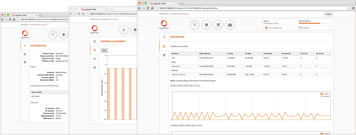

.png)
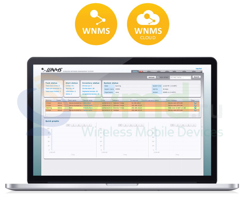
.png)
.png)
