-
Contents
-
Table of Contents
-
Troubleshooting
-
Bookmarks
Quick Links
Show/Hide Bookmarks
EDB8200UE
00398283
Operating Instructions
Global Drive
Frequency inverters
8200 series
K35.0110-3
Related Manuals for Lenze 8201
Summary of Contents for Lenze 8201
-
Page 1
Show/Hide Bookmarks EDB8200UE 00398283 Operating Instructions K35.0110-3 Global Drive Frequency inverters 8200 series… -
Page 2
Show/Hide Bookmarks These Operating Instructions are valid for the 82XX controllers of the versions: 33.820X- (8201 — 8204) 33.8202- -V002 reduced assembly depth (8202) Type Design: B = Module C = Cold Plate E = Enclosure IP20 Hardware level and index… -
Page 3: Table Of Contents
….3.2.1 Types 8201 to 8204 ……
-
Page 4
Show/Hide Bookmarks Contents 5 Commissioning ……… 5- 1 5.1 Before you switch on . -
Page 5: Preface And General Information
1.1.1 Terminology used Term In the following text used for 82XX Any frequency inverter of the series 8200, 8210, 8220, 8240 Controller 82XX frequency inverter Drive system Drive systems with 82XX frequency inverters and other Lenze drive components 820XBA1097…
-
Page 6: What Is New
1 82XX frequency inverter After receipt of the delivery, check immediately whether the scope of supply matches with the accompanying 1 Operating Instructions papers. Lenze does not accept any liability for deficiencies 1 accessory kit (components for claimed subsequently. the mechanical and electric…
-
Page 7: Legal Regulations
1.3 Legal regulations Labelling Labelling Nameplate CE mark Manufacturer Conforms to the EC Low Voltage Lenze GmbH & Co KG Directive Postfach 101352 D-31763 Hameln Application 82XX frequency inverter as directed must only be operated under the conditions prescribed in these Instructions.
-
Page 8
Operating Instructions. The specifications, processes, and circuitry described in these Operating Instructions are for guidance only and must be adapted to your own specific application. Lenze does not take responsibility for the suitability of the process and circuit proposals. -
Page 9: Safety Information
Show/Hide Bookmarks Safety information 2 Safety information 2.1 General safety information Safety and application notes for controllers (to: Low-Voltage Directive 73/23/EEC) 1. General to the regulations of the EC Directive 89/392/EEC (Machinery Directive); EN 60204 must be observed. During operation, drive controllers may have, according Commissioning (i.e.
-
Page 10
Show/Hide Bookmarks Safety information inappropriate handling. Electrical components must not 6. Operation be damaged or destroyed mechanically (health risks are Systems where drive controllers are installed must be possible!). equipped, if necessary, with additional monitoring and protective devices according to the valid safety regulations, e.g. -
Page 11: Layout Of The Safety Information
Show/Hide Bookmarks Safety information 2.2 Layout of the safety information All safety notes have a uniform layout: — The icon characterizes the type of danger. — The signal word characterizes the severity of danger. — The note describes the danger and suggests how to avoid the danger.
-
Page 12: Residual Hazards
Show/Hide Bookmarks Safety information 2.3 Residual hazards Operator’s safety After mains disconnections, the power terminals U, V, W and + U , -U remain live for at least three minutes. Before working on the controller, check that no voltage is applied to the power terminals. Protection of Cyclic connection and disconnection of the controller supply voltage at L1, L2, L3 or + U devices…
-
Page 13: Technical Data
Show/Hide Bookmarks Technical Data 3 Technical data 3.1 General data/application conditions Field Values Vibration resistance Germanischer Lloyd, general conditions Humidity class Humidity class F without condensation (average relative humidity 85 %) ˜ ¤ ˜ Permissible Permissible during transport of the controller: + 70 temperature ranges temperature ranges…
-
Page 14: Rated Data (Operation With 150 % Overload)
Show/Hide Bookmarks Technical Data 3.2 Rated data (Operation with 150 % overload) 3.2.1 Types 8201 to 8204 150 % overload Type 8201 8202 8203 8204 Order no. EVF8201-E EVF8202-E EVF8203-E EVF8204-E Variant ”reduced assembly Variant ”reduced assembly Type 8202-V002 depth”…
-
Page 15
Show/Hide Bookmarks Technical Data 150 % overload Type 8201 8202 8203 8204 Order no. EVF8201-E EVF8202-E EVF8203-E EVF8204-E Variant ”reduced assembly Variant ”reduced assembly Type 8202-V002 depth” depth” Order no. EVF8202-E- V002 ˜ ˜ Power derating [%/K] C < T <… -
Page 16: Fuses And Cable Cross-Sections
Operation without mains filter/mains choke Operation with mains filter/mains choke Fuse E.l.c.b. Cable Fuse E.l.c.b. Cable F1, F2, F3 cross-section F1, F2, F3 cross-section 8201 M 10A C 10A M 10A C 10A 8202 M 15A C 16A M 15A C 16A [1.5] [15]…
-
Page 17: Installation
Show/Hide Bookmarks Installation 4 Installation 4.1 Mechanical installation 4.1.1 Important notes Use the controllers only as built-in devices! If the cooling air contains pollutants (dust, fluff, grease, aggressive gases): — take suitable preventive measures , e.g. separate air duct, installation of filters, regular cleaning, etc. Observe free space! — You can install several controllers next to each other without free space in a control cabinet.
-
Page 18
Show/Hide Bookmarks Installation Possible mounting positions In vertical position at the back of the control cabinet, terminals point to the front: — With attached fixing rails. — With special fixing unit on one or two DIN rails. ˜ Turned by 90 (flat assembly on the backside of the control cabinet): — Insert the attached fixing rail into the guides at the heat… -
Page 19: Standard Assembly With Fixing Rails Or Fixing Angles
P o st fac h10 135 2 , 3 17 63 H AM EL N K35.0074 FIG 4-1 Dimensions 8201 — 8204: Standard assembly Fixing rail for side assembly Observe the free space required for the connection cables With attachable fieldbus or I/O module:…
-
Page 20: Type 8202-V002 (Reduced Assembly Depth)
Show/Hide Bookmarks Installation 4.1.2.2 Type 8202-V002 (reduced assembly depth) This variant is equipped with a heat sink with a smaller surface. Observe the following points to comply with the technical data: Assembly on an unpainted, metallic assembly board. Area > 0.15 m Sheet thickness at least 2 mm.
-
Page 21: Din-Rail Assembly
FIG 4-2 Dimensions 8201 — 8204: DIN-rail assembly 8201/8202: Assembly on a DIN rail (middle) or on two DIN rails (top and bottom) possible 8203 — 8204: Assembly on two DIN rails Observe the free space required for the connection cables…
-
Page 22: Electrical Installation
With isolated neutral Operation with recommended Mains filter will be destroyed if (IT mains) mains filters is not possible ”earth fault” occurs. Contact Lenze. With grounded phase Operation only possible with one Contact Lenze variant DC supply via + U…
-
Page 23: Power Connections
— Tightening torques Terminals L1, L2, L3, + UG, -UG PE connection Type 8201 — 8204 0.5 … 0.6 Nm (4.4 … 5.3 lbin) 3.4 Nm (30 lbin) 4.2.2.2 Motor connection Because of the EMC safety we recommend the use of screened motor cables only.
-
Page 24
No. of motor cables — When using unscreened motor cables, the data indicated in FIG 4-3 are valid for the double motor-cable length. — Please contact Lenze when the absolute or resulting motor-cable lengths are > 200 m. Type Permissible control mode C014… -
Page 25: Connection Diagram
Show/Hide Bookmarks Installation 4.2.2.3 Connection diagram Fuse F2* Fuse only for supply with 2AC / PE / 190-260V K10 Mains contactor K10* Mains contactor only for supply with 2AC / PE / 190-260V Mains filter/mains choke, see Accessories ϑ Motor filter/sine filter, see Accessories Brake chopper/brake module, see Accessories…
-
Page 26: Control Connections
Show/Hide Bookmarks Installation 4.2.3 Control connections 4.2.3.1 Control cables We recommend the unilateral screening of all cables for analog signals to avoid signal distortion. Connect the screens of the control cables as follows: — 820X: On the front FAST-ON connector. If the control cables are interrupted (terminal strips, relays), the screens must be reconnected over the shortest possible distance.
-
Page 27
Show/Hide Bookmarks Installation Terminal Level Data (Factory setting is printed in bold) Analog GND 1 inputs inputs Setpoint input, 5 — 6 0 to 20 mA Resolution: 9 bit reference: ™ 5 — 6 4 to 20 mA Linearity fault: 0.5 % Terminal 7 3 — 4… -
Page 28: Connection Diagrams
Show/Hide Bookmarks Installation 4.2.3.3 Connection diagrams ≥ K35.0077-3 FIG 4-6 Control connections: Supply with internal control voltage ≥ K35.0077-4 FIG 4-7 Control connections: External voltage supply (+12 V … +30 V) GND1 Reference for internal voltages GND2 Reference for external voltages GND1 and GND2 have a potential isolation inside the unit.
-
Page 29: Installation Of A Ce-Typical Drive System
Show/Hide Bookmarks Installation 4.3 Installation of a CE-typical drive system General The user is responsible for the compliance of his application with the EC directives. notes — If you observe the following measure you can be sure that the drive system will not cause any EMC problems, i.e.
-
Page 30
Show/Hide Bookmarks Installation Screening Connect the screen of the motor cable with the controller — to the screen connection of the controller. — additionally to the mounting plate with a surface as large as possible. — Recommendation: For the connection, use ground clamps on bare metal mounting surfaces. If contactors, motor-protecting switches or terminals are located in the motor cable: — Connect the screens of the connected cables also to the mounting plate, with a surface as large as possible. -
Page 31
Show/Hide Bookmarks Installation K35.0082 FIG 4-8 Example for an installation in accordance with the EMC regulations: Fuse Mains contactor Mains filter ”A” or ”B”, see Accessories Motor filter/sine filter, see Accessories Brake module/brake chopper, see Accessories Terminal strip in control cabinet Brake resistor HF screen because of a PE connection with a surface as large as possible (see ”Screening”… -
Page 32
Show/Hide Bookmarks Installation 4-16 820XBA1097… -
Page 33: Commissioning
230/400V , 50Hz. Further settings are not necessary. Only a few settings via the 8201 BB operating module or a fieldbus module are necessary to adapt your drive to your application. The steps required are summarized in chapter 5.3 and in chapter 5.4.
-
Page 34: Short Set-Up (Factory Setting)
Show/Hide Bookmarks Commissioning In case of condensation connect the controller to mains voltage only after the visible humidity has evaporated. The plug-in power terminals of the 820X controller must only be connected or disconnected when no voltage is applied. Maintain the switch-on sequence! 5.2 Short set-up (Factory setting) 5.2.1 Switch-on sequence…
-
Page 35: Factory Setting Of The Most Important Drive Parameters
Show/Hide Bookmarks Commissioning 5.2.2 Factory setting of the most important drive parameters Setting Code Factory setting Adaption to application Operating mode C001 Setpoint selection via terminal 8 See code table, Control via terminals chapter 7.2 Parameter setting via 8201BB Terminal configuration C007 See code table,…
-
Page 36: Adapt Machine Data
Show/Hide Bookmarks Commissioning 5.3 Adapt machine data 5.3.1 Determine speed range (f dmin, dmax) Code Name Possible settings IMPORTANT Lenze Selection Info C010 Minimum field {0.1Hz} 480.0 frequency C011 Maximum field 50.0 30.0 {0.1Hz} 480.0 frequency Function The speed range required for the application can be selected here by determing the…
-
Page 37
Show/Hide Bookmarks Commissioning Important With the setting of f > f the field frequency is limited to f dmin dmax dmax When selecting the setpoint by means of JOG values, f acts as limitation. dmax is an internal standardization variable: dmax — Use the LECOM interface only for important modifications, when the controller is inhibited. -
Page 38: Adjustment Of Acceleration And Deceleration Times (Tir , T If)
Show/Hide Bookmarks Commissioning 5.3.2 Adjustment of acceleration and deceleration times (T Code Name Possible settings IMPORTANT Lenze Selection Info C012 Acceleration time {0.1s} 999.0 T C013 Deceleration time {0.1s} 999.0 T Function The accleration and deceleration times determine the time required by the drive to follow a setpoint change.
-
Page 39: Setting Of The Current Limit (Imax)
Show/Hide Bookmarks Commissioning 5.3.3 Setting of the current limit (I Code Name Possible settings IMPORTANT Lenze Selection Info C022 I limit {1 %} motor mode C023 I limit {1 %} generator mode Function The controllers are equipped with a current-limit control which determines the dynamic response under load.
-
Page 40: Optimisation Of The Operating Characteristic Of The Drive
In chapter 5.4.1 you will find some more information to help you with the selection. 5.4.1 Select the control mode Code Name Possible settings IMPORTANT Lenze Selection Info § C014 Operating mode Linear characteristic V with Control auto boost…
-
Page 41
Show/Hide Bookmarks Commissioning C014 = -0- C014 = -1- Linear characteristic Square-law characteristic (e. g. for pumps, fans) V o u t V o u t 1 0 0 % 1 0 0 % A u t o b o o s t V m i n A u t o b o o s t… -
Page 42
Show/Hide Bookmarks Commissioning Help for decision Motor cable screened > 25 m screened 25 m unscreened > 50 m unscreened 50 m C014 recommended alternatively recommended alternatively Single drives With constant load With changing loads With heavy start conditions High dynamic posotioning and feed drives Lifts and hoists Pumps and fan drives Three-phase reluctance motors… -
Page 43: Optimisation Of V/F-Characteristic Control With Auto Boost
Show/Hide Bookmarks Commissioning 5.4.1.1 Optimisation of V/f-characteristic control with auto boost Codes required Code Name Possible settings IMPORTANT Lenze Selection Info C015 V/f-rated 50.0 30.0 {0.1Hz} 960.0 frequency C016 V setting {1 %} * type dependent C021 Slip {1 %}…
-
Page 44
Show/Hide Bookmarks Commissioning 3. Set the Vmin boost Load-dependentboost of the motor voltage in the field-frequency range below the (C016). V/f-rated frequency. C016 acts as gain factor of the auto-boost function. Adjustment In general, an adjustment is not necessary. An optimisation can be advantageous: For drives with very high starting torques: A Operate the motor under load. -
Page 45: Optimisation Of V/F-Characteristic Control
Show/Hide Bookmarks Commissioning 5.4.1.2 Optimisation of V/f-characteristic control Codes required Code Name Possible settings IMPORTANT Lenze Selection Info C015 V/f-rated 50.0 30.0 {0.1Hz} 960.0 frequency C016 V setting {1 %} * type dependent C021 Slip {1 %} compensation Setting sequence 1.
-
Page 46
Show/Hide Bookmarks Commissioning 3. Set the Vmin boost Load-independentboost of the motor voltage for field frequencies below the (C016). U/f-rated frequency. You can thus optimize the torque performance of the inverter drive. It is absolutely necessary to adapt the asynchronous motor used, since otherwise, the motor can be destroyed by overtemperatue: Adjustment Please note the thermal characteristic of the connected motor under small field… -
Page 47: During Operation
Show/Hide Bookmarks During operation 6 During operation Replace defective fuses with the prescribed type only when no voltage is applied. There are no fuses in the controller. Cyclic mains switching: — Do not switch on the controller more than every 3 minutes, otherwise the internal initial-current limitation can be overloaded.
-
Page 48
Show/Hide Bookmarks During operation If you use the function CW/CCW (selection of the direction of rotation) with the configuration C007 = -0- to -13-: — The drive can reverse the direction of rotation in the event of a control-voltage failure or a cable break. If you use the function ”Flying-restart circuit”… -
Page 49: Configuration
Show/Hide Bookmarks Configuration 7 Configuration 7.1 Basics The configuration of the controller is used to adapt the drive to your applications. For this, you have the following functions available: — Operating functions — Control function — Display functions — Monitoring functions The possible function settings are organized in codes: — Codes are numerically sorted, starting from the code with the smallest number to the one with the highest number.
-
Page 50: Code Table
Name Name of the code. 820X Unit-specific setting possibilites (here for 820X). Without unit designation the code is valid for all unit types. Lenze Factory setting of the code The column ”Important” contains further information Selection {1 %} 99 Minimum value…
-
Page 51
Show/Hide Bookmarks Configuration Code Name Possible settings IMPORTANT Code Name IMPORTANT Lenze Selection Info C001 Operating mode Setpoint selection via term. 8 § Control via terminals Parameter setting via 8201BB Setpoint selection via 8201BB or via LECOM Control via terminals Parameter setting via 8201BB Setpoint selection via term. -
Page 52
Show/Hide Bookmarks Configuration Code Code Name Name Possible settings IMPORTANT IMPORTANT Lenze Selection Info [C007 Terminal CW = CW configuration rotation CW/CCWDC brake JOG1/2/3 CCW = CW/CCWPAR JOG1/2/3 CW/CCWQSP JOG1/2/3 rotation CW/CCWPAR DC brake JOG1 DC brake = CW/CCWQSP JOG1… -
Page 53
Show/Hide Bookmarks Configuration Code Code Name Name Possible settings IMPORTANT IMPORTANT Lenze Selection Info C009* Device address Only for LECOM applications C010 Minimum field {0.1Hz} 480.0 frequency C011 Maximum field frequency 820X 50.0 30.0 {0.1Hz} 480.0 821X 50.0 {0.1Hz} 480.0 (Software 2x) 30.0… -
Page 54
Show/Hide Bookmarks Configuration Code Code Name Name Possible settings IMPORTANT IMPORTANT Lenze Selection Info C016 V C016 setting 820X {1 %} * depends on the unit 821X/822X {1 %} / 824X C017 Threshold Q {0.1Hz} 480.0 C018 Chopper § §… -
Page 55
Show/Hide Bookmarks Configuration Code Code Name Name Possible settings IMPORTANT IMPORTANT Lenze Selection Info C038 JOG value 2 {1Hz} C039 JOG value 3 {1Hz} C050* Output Only display frequency C052* Motor voltage Only display C054* Motor current Only display C056* Controller load… -
Page 56
Show/Hide Bookmarks Configuration Code Code Name Name Possible settings IMPORTANT IMPORTANT Lenze Selection Info C099* Software version Only display 820X 82 1x (Software 1x) 821X 82 2x (Software 2x) 82 1x (Software 1x) 822X/824X 82 1x (Software 1x) C105 Deceleration time quick stop 5.00… -
Page 57
Show/Hide Bookmarks Configuration Code Code Name Name Possible settings IMPORTANT IMPORTANT Lenze Selection Info C117 Function relay § Ready for operation 822X/824X TRIP fault message Motor is running Motor is running / CW rotation Motor is running / CCW rotation… -
Page 58
{1s} Auto-TRIP-Reset C178* Operating time Only display C179* Mains switch-on Only display time C377 Gain Zk-voltage Should only detection be changed by the Lenze 822X/824X Service! C500* Display factor application datum numerator 821X/822X/824 2000 1 25000 C501* Display factor for process… -
Page 59: Troubleshooting And Fault Elimination
Show/Hide Bookmarks Troubleshooting and fault elimination 8 Troubleshooting and fault elimination Faults are immediately indicated via the display or status information (chapter 8.1). The fault can be analysed by using the history buffer (chapter 8.2) and the list in chapter 8.3. The list helps you with the elimination of faults.
-
Page 60: Maloperation Of The Drive
Show/Hide Bookmarks Troubleshooting and fault elimination 8.1.3 Maloperation of the drive Maloperation Possible causes Motor does not rotate DC-bus voltage too low (red LED is blinking every 0.4 s; message LU is displayed) Controller inhibited (green LED is blinking, display of the operating module: OFF, STOP or AS_LC) Setpoint = 0 DC braking active…
-
Page 61: Fault Indications
No fault External fault (TRIP-Set) A digital input assigned to the Check external encoder TRIP-Set function has been activated Internal fault Contact Lenze Undervoltage DC-bus voltage too low Check mains voltage Check supply module Short circuit Short circuit Find out cause of short circuit; check…
-
Page 62
Show/Hide Bookmarks Troubleshooting and fault elimination Display Fault Cause Remedy Heat sink temperature is Ambient temperature Allow controller to cool and ensure higher than the value set ˜ ˜ > + 40 C or + 50 ventilation in the controller Check the ambient temperature in the control cabinet Heat sink very dirty… -
Page 63: Reset Of Fault Indications
TRIP. Note! If the TRIP source is still active, the TRIP cannot be reset. Code Name Possible settings IMPORTANT Lenze Selection Info § C170 TRIP-reset TRIP-reset by pressing the STP selection key or a LOW signal at ctrl.
-
Page 64
Show/Hide Bookmarks Troubleshooting and fault elimination Function You can select whether the active fault is to be reset automatically or manually. Auto-Trip reset does not reset all faults automatically. Activation C170 = -0-: Manual TRIP-reset STP key LOW signal at terminal 28 C170 = -1-: Auto-Trip reset resets the following fault messages after the time set under C171: — OC3 (overload during acceleration) -
Page 65: Accessories (Overview)
Show/Hide Bookmarks Accessories 9 Accessories (Overview) 9.1 Accessories for all types Name Order number 8201BB operating module EMZ8201BB Diagnosis terminal (2.5 m cable) EMZ8272BB-V001 Diagnosis terminal (5.0 m cable) EMZ8272BB-V002 Diagnosis terminal (10 m cable) EMZ8272BB-V003 Digital display EPD203 Setpoint potentiometer ERPD0001k0001W Rotary button for potentiometer ERZ0001…
-
Page 66: Software
Show/Hide Bookmarks Accessories 9.2 Software Name Order number PC program for Global Drive controllers ESP-GDC 1 9.3 Type-specific accessories Name Order number 8201 8202 8203 8204 E.l.c.b. EFA1C10A EFA1C16A EFA1C20A EFA1C20A Fuse EFSM-0100ASB EFSM-0150ASB EFSM-0200ASC EFSM-0200ASC Fuse holder EFH30001 EFH30001…
-
Page 67: Index
Show/Hide Bookmarks Index Index Connection Control, Connection diagram, 4-12 Acceleration times, 5-6 Control cables, 4-10 Adapt the motor, 5-8 Mains, 4-7 Motor, 4-7 Application, as directed, 1-3 Power, Circuit diagram, 4-9 Application conditions, 2-1 Connection diagram Applications as directed, 1-3 Control connections, 4-12 Approvals, 2-1 Power connection, 4-9…
-
Page 68
Show/Hide Bookmarks Index Fault analysis, 8-2 Fault messages, 8-3 Deceleration times, 5-6 Reset, 8-5 Definitions of terminology used, 1-1 Field frequency Maximum, 5-4 Degree of pollution, 2-1 Minimum, 5-4 Dimensions Frequency inverter. Siehe Controller 8202-V002 reduced assembly depth, 4-4 Fuses, Single drives, 3-4 820X with fixing rail, 4-3 150 % overload, 3-4 Controller, 3-4… -
Page 69
Labelling, Controller, 1-3 LED, 8-1 Packaging, 2-1 Legal regulations, 1-3 Power connections, 4-7 Liability, 1-4 Rated data, Types 8201-8204, 150 % Mains connection, 4-7 overload, 3-2 Mains-voltage compensation, 5-11, 5-13 Relay output, 4-11 Maloperation of the drive, 8-2 Reset, Fault message, 8-5… -
Page 70
Show/Hide Bookmarks Index Technical data, 2-1 Unit protection, 2-4 General data/application conditions, 2-1 Temperature ranges, 2-1 Transport, storage, 2-1 Variant, V002, 4-4 TRIP, 8-5 Vibration resistance, 2-1 Troubleshooting, 8-1 Display at the operating module , 8-1 Vmin setting, Drives with special motors, Fault analysis using the history buffer , 8-2 5-12 Fault indication, 8-3…
-
Page 1
Show/Hide Bookmarks EDB8200UE 00398283 Operating Instructions K35.0110-3 Global Drive Frequency inverters 8200 series… -
Page 2
Show/Hide Bookmarks These Operating Instructions are valid for the 82XX controllers of the versions: 33.820X- (8201 — 8204) 33.8202- -V002 reduced assembly depth (8202) Type Design: B = Module C = Cold Plate E = Enclosure IP20 Hardware level and index… -
Page 3: Table Of Contents
….3.2.1 Types 8201 to 8204 ……
-
Page 4
Show/Hide Bookmarks Contents 5 Commissioning ……… 5- 1 5.1 Before you switch on . -
Page 5: Preface And General Information
1.1.1 Terminology used Term In the following text used for 82XX Any frequency inverter of the series 8200, 8210, 8220, 8240 Controller 82XX frequency inverter Drive system Drive systems with 82XX frequency inverters and other Lenze drive components 820XBA1097…
-
Page 6: What Is New
1 82XX frequency inverter After receipt of the delivery, check immediately whether the scope of supply matches with the accompanying 1 Operating Instructions papers. Lenze does not accept any liability for deficiencies 1 accessory kit (components for claimed subsequently. the mechanical and electric…
-
Page 7: Legal Regulations
1.3 Legal regulations Labelling Labelling Nameplate CE mark Manufacturer Conforms to the EC Low Voltage Lenze GmbH & Co KG Directive Postfach 101352 D-31763 Hameln Application 82XX frequency inverter as directed must only be operated under the conditions prescribed in these Instructions.
-
Page 8
Operating Instructions. The specifications, processes, and circuitry described in these Operating Instructions are for guidance only and must be adapted to your own specific application. Lenze does not take responsibility for the suitability of the process and circuit proposals. -
Page 9: Safety Information
Show/Hide Bookmarks Safety information 2 Safety information 2.1 General safety information Safety and application notes for controllers (to: Low-Voltage Directive 73/23/EEC) 1. General to the regulations of the EC Directive 89/392/EEC (Machinery Directive); EN 60204 must be observed. During operation, drive controllers may have, according Commissioning (i.e.
-
Page 10
Show/Hide Bookmarks Safety information inappropriate handling. Electrical components must not 6. Operation be damaged or destroyed mechanically (health risks are Systems where drive controllers are installed must be possible!). equipped, if necessary, with additional monitoring and protective devices according to the valid safety regulations, e.g. -
Page 11: Layout Of The Safety Information
Show/Hide Bookmarks Safety information 2.2 Layout of the safety information All safety notes have a uniform layout: — The icon characterizes the type of danger. — The signal word characterizes the severity of danger. — The note describes the danger and suggests how to avoid the danger.
-
Page 12: Residual Hazards
Show/Hide Bookmarks Safety information 2.3 Residual hazards Operator’s safety After mains disconnections, the power terminals U, V, W and + U , -U remain live for at least three minutes. Before working on the controller, check that no voltage is applied to the power terminals. Protection of Cyclic connection and disconnection of the controller supply voltage at L1, L2, L3 or + U devices…
-
Page 13: Technical Data
Show/Hide Bookmarks Technical Data 3 Technical data 3.1 General data/application conditions Field Values Vibration resistance Germanischer Lloyd, general conditions Humidity class Humidity class F without condensation (average relative humidity 85 %) ˜ ¤ ˜ Permissible Permissible during transport of the controller: + 70 temperature ranges temperature ranges…
-
Page 14: Rated Data (Operation With 150 % Overload)
Show/Hide Bookmarks Technical Data 3.2 Rated data (Operation with 150 % overload) 3.2.1 Types 8201 to 8204 150 % overload Type 8201 8202 8203 8204 Order no. EVF8201-E EVF8202-E EVF8203-E EVF8204-E Variant ”reduced assembly Variant ”reduced assembly Type 8202-V002 depth”…
-
Page 15
Show/Hide Bookmarks Technical Data 150 % overload Type 8201 8202 8203 8204 Order no. EVF8201-E EVF8202-E EVF8203-E EVF8204-E Variant ”reduced assembly Variant ”reduced assembly Type 8202-V002 depth” depth” Order no. EVF8202-E- V002 ˜ ˜ Power derating [%/K] C < T <… -
Page 16: Fuses And Cable Cross-Sections
Operation without mains filter/mains choke Operation with mains filter/mains choke Fuse E.l.c.b. Cable Fuse E.l.c.b. Cable F1, F2, F3 cross-section F1, F2, F3 cross-section 8201 M 10A C 10A M 10A C 10A 8202 M 15A C 16A M 15A C 16A [1.5] [15]…
-
Page 17: Installation
Show/Hide Bookmarks Installation 4 Installation 4.1 Mechanical installation 4.1.1 Important notes Use the controllers only as built-in devices! If the cooling air contains pollutants (dust, fluff, grease, aggressive gases): — take suitable preventive measures , e.g. separate air duct, installation of filters, regular cleaning, etc. Observe free space! — You can install several controllers next to each other without free space in a control cabinet.
-
Page 18
Show/Hide Bookmarks Installation Possible mounting positions In vertical position at the back of the control cabinet, terminals point to the front: — With attached fixing rails. — With special fixing unit on one or two DIN rails. ˜ Turned by 90 (flat assembly on the backside of the control cabinet): — Insert the attached fixing rail into the guides at the heat… -
Page 19: Standard Assembly With Fixing Rails Or Fixing Angles
P o st fac h10 135 2 , 3 17 63 H AM EL N K35.0074 FIG 4-1 Dimensions 8201 — 8204: Standard assembly Fixing rail for side assembly Observe the free space required for the connection cables With attachable fieldbus or I/O module:…
-
Page 20: Type 8202-V002 (Reduced Assembly Depth)
Show/Hide Bookmarks Installation 4.1.2.2 Type 8202-V002 (reduced assembly depth) This variant is equipped with a heat sink with a smaller surface. Observe the following points to comply with the technical data: Assembly on an unpainted, metallic assembly board. Area > 0.15 m Sheet thickness at least 2 mm.
-
Page 21: Din-Rail Assembly
FIG 4-2 Dimensions 8201 — 8204: DIN-rail assembly 8201/8202: Assembly on a DIN rail (middle) or on two DIN rails (top and bottom) possible 8203 — 8204: Assembly on two DIN rails Observe the free space required for the connection cables…
-
Page 22: Electrical Installation
With isolated neutral Operation with recommended Mains filter will be destroyed if (IT mains) mains filters is not possible ”earth fault” occurs. Contact Lenze. With grounded phase Operation only possible with one Contact Lenze variant DC supply via + U…
-
Page 23: Power Connections
— Tightening torques Terminals L1, L2, L3, + UG, -UG PE connection Type 8201 — 8204 0.5 … 0.6 Nm (4.4 … 5.3 lbin) 3.4 Nm (30 lbin) 4.2.2.2 Motor connection Because of the EMC safety we recommend the use of screened motor cables only.
-
Page 24
No. of motor cables — When using unscreened motor cables, the data indicated in FIG 4-3 are valid for the double motor-cable length. — Please contact Lenze when the absolute or resulting motor-cable lengths are > 200 m. Type Permissible control mode C014… -
Page 25: Connection Diagram
Show/Hide Bookmarks Installation 4.2.2.3 Connection diagram Fuse F2* Fuse only for supply with 2AC / PE / 190-260V K10 Mains contactor K10* Mains contactor only for supply with 2AC / PE / 190-260V Mains filter/mains choke, see Accessories ϑ Motor filter/sine filter, see Accessories Brake chopper/brake module, see Accessories…
-
Page 26: Control Connections
Show/Hide Bookmarks Installation 4.2.3 Control connections 4.2.3.1 Control cables We recommend the unilateral screening of all cables for analog signals to avoid signal distortion. Connect the screens of the control cables as follows: — 820X: On the front FAST-ON connector. If the control cables are interrupted (terminal strips, relays), the screens must be reconnected over the shortest possible distance.
-
Page 27
Show/Hide Bookmarks Installation Terminal Level Data (Factory setting is printed in bold) Analog GND 1 inputs inputs Setpoint input, 5 — 6 0 to 20 mA Resolution: 9 bit reference: ™ 5 — 6 4 to 20 mA Linearity fault: 0.5 % Terminal 7 3 — 4… -
Page 28: Connection Diagrams
Show/Hide Bookmarks Installation 4.2.3.3 Connection diagrams ≥ K35.0077-3 FIG 4-6 Control connections: Supply with internal control voltage ≥ K35.0077-4 FIG 4-7 Control connections: External voltage supply (+12 V … +30 V) GND1 Reference for internal voltages GND2 Reference for external voltages GND1 and GND2 have a potential isolation inside the unit.
-
Page 29: Installation Of A Ce-Typical Drive System
Show/Hide Bookmarks Installation 4.3 Installation of a CE-typical drive system General The user is responsible for the compliance of his application with the EC directives. notes — If you observe the following measure you can be sure that the drive system will not cause any EMC problems, i.e.
-
Page 30
Show/Hide Bookmarks Installation Screening Connect the screen of the motor cable with the controller — to the screen connection of the controller. — additionally to the mounting plate with a surface as large as possible. — Recommendation: For the connection, use ground clamps on bare metal mounting surfaces. If contactors, motor-protecting switches or terminals are located in the motor cable: — Connect the screens of the connected cables also to the mounting plate, with a surface as large as possible. -
Page 31
Show/Hide Bookmarks Installation K35.0082 FIG 4-8 Example for an installation in accordance with the EMC regulations: Fuse Mains contactor Mains filter ”A” or ”B”, see Accessories Motor filter/sine filter, see Accessories Brake module/brake chopper, see Accessories Terminal strip in control cabinet Brake resistor HF screen because of a PE connection with a surface as large as possible (see ”Screening”… -
Page 32
Show/Hide Bookmarks Installation 4-16 820XBA1097… -
Page 33: Commissioning
230/400V , 50Hz. Further settings are not necessary. Only a few settings via the 8201 BB operating module or a fieldbus module are necessary to adapt your drive to your application. The steps required are summarized in chapter 5.3 and in chapter 5.4.
-
Page 34: Short Set-Up (Factory Setting)
Show/Hide Bookmarks Commissioning In case of condensation connect the controller to mains voltage only after the visible humidity has evaporated. The plug-in power terminals of the 820X controller must only be connected or disconnected when no voltage is applied. Maintain the switch-on sequence! 5.2 Short set-up (Factory setting) 5.2.1 Switch-on sequence…
-
Page 35: Factory Setting Of The Most Important Drive Parameters
Show/Hide Bookmarks Commissioning 5.2.2 Factory setting of the most important drive parameters Setting Code Factory setting Adaption to application Operating mode C001 Setpoint selection via terminal 8 See code table, Control via terminals chapter 7.2 Parameter setting via 8201BB Terminal configuration C007 See code table,…
-
Page 36: Adapt Machine Data
Show/Hide Bookmarks Commissioning 5.3 Adapt machine data 5.3.1 Determine speed range (f dmin, dmax) Code Name Possible settings IMPORTANT Lenze Selection Info C010 Minimum field {0.1Hz} 480.0 frequency C011 Maximum field 50.0 30.0 {0.1Hz} 480.0 frequency Function The speed range required for the application can be selected here by determing the…
-
Page 37
Show/Hide Bookmarks Commissioning Important With the setting of f > f the field frequency is limited to f dmin dmax dmax When selecting the setpoint by means of JOG values, f acts as limitation. dmax is an internal standardization variable: dmax — Use the LECOM interface only for important modifications, when the controller is inhibited. -
Page 38: Adjustment Of Acceleration And Deceleration Times (Tir , T If)
Show/Hide Bookmarks Commissioning 5.3.2 Adjustment of acceleration and deceleration times (T Code Name Possible settings IMPORTANT Lenze Selection Info C012 Acceleration time {0.1s} 999.0 T C013 Deceleration time {0.1s} 999.0 T Function The accleration and deceleration times determine the time required by the drive to follow a setpoint change.
-
Page 39: Setting Of The Current Limit (Imax)
Show/Hide Bookmarks Commissioning 5.3.3 Setting of the current limit (I Code Name Possible settings IMPORTANT Lenze Selection Info C022 I limit {1 %} motor mode C023 I limit {1 %} generator mode Function The controllers are equipped with a current-limit control which determines the dynamic response under load.
-
Page 40: Optimisation Of The Operating Characteristic Of The Drive
In chapter 5.4.1 you will find some more information to help you with the selection. 5.4.1 Select the control mode Code Name Possible settings IMPORTANT Lenze Selection Info § C014 Operating mode Linear characteristic V with Control auto boost…
-
Page 41
Show/Hide Bookmarks Commissioning C014 = -0- C014 = -1- Linear characteristic Square-law characteristic (e. g. for pumps, fans) V o u t V o u t 1 0 0 % 1 0 0 % A u t o b o o s t V m i n A u t o b o o s t… -
Page 42
Show/Hide Bookmarks Commissioning Help for decision Motor cable screened > 25 m screened 25 m unscreened > 50 m unscreened 50 m C014 recommended alternatively recommended alternatively Single drives With constant load With changing loads With heavy start conditions High dynamic posotioning and feed drives Lifts and hoists Pumps and fan drives Three-phase reluctance motors… -
Page 43: Optimisation Of V/F-Characteristic Control With Auto Boost
Show/Hide Bookmarks Commissioning 5.4.1.1 Optimisation of V/f-characteristic control with auto boost Codes required Code Name Possible settings IMPORTANT Lenze Selection Info C015 V/f-rated 50.0 30.0 {0.1Hz} 960.0 frequency C016 V setting {1 %} * type dependent C021 Slip {1 %}…
-
Page 44
Show/Hide Bookmarks Commissioning 3. Set the Vmin boost Load-dependentboost of the motor voltage in the field-frequency range below the (C016). V/f-rated frequency. C016 acts as gain factor of the auto-boost function. Adjustment In general, an adjustment is not necessary. An optimisation can be advantageous: For drives with very high starting torques: A Operate the motor under load. -
Page 45: Optimisation Of V/F-Characteristic Control
Show/Hide Bookmarks Commissioning 5.4.1.2 Optimisation of V/f-characteristic control Codes required Code Name Possible settings IMPORTANT Lenze Selection Info C015 V/f-rated 50.0 30.0 {0.1Hz} 960.0 frequency C016 V setting {1 %} * type dependent C021 Slip {1 %} compensation Setting sequence 1.
-
Page 46
Show/Hide Bookmarks Commissioning 3. Set the Vmin boost Load-independentboost of the motor voltage for field frequencies below the (C016). U/f-rated frequency. You can thus optimize the torque performance of the inverter drive. It is absolutely necessary to adapt the asynchronous motor used, since otherwise, the motor can be destroyed by overtemperatue: Adjustment Please note the thermal characteristic of the connected motor under small field… -
Page 47: During Operation
Show/Hide Bookmarks During operation 6 During operation Replace defective fuses with the prescribed type only when no voltage is applied. There are no fuses in the controller. Cyclic mains switching: — Do not switch on the controller more than every 3 minutes, otherwise the internal initial-current limitation can be overloaded.
-
Page 48
Show/Hide Bookmarks During operation If you use the function CW/CCW (selection of the direction of rotation) with the configuration C007 = -0- to -13-: — The drive can reverse the direction of rotation in the event of a control-voltage failure or a cable break. If you use the function ”Flying-restart circuit”… -
Page 49: Configuration
Show/Hide Bookmarks Configuration 7 Configuration 7.1 Basics The configuration of the controller is used to adapt the drive to your applications. For this, you have the following functions available: — Operating functions — Control function — Display functions — Monitoring functions The possible function settings are organized in codes: — Codes are numerically sorted, starting from the code with the smallest number to the one with the highest number.
-
Page 50: Code Table
Name Name of the code. 820X Unit-specific setting possibilites (here for 820X). Without unit designation the code is valid for all unit types. Lenze Factory setting of the code The column ”Important” contains further information Selection {1 %} 99 Minimum value…
-
Page 51
Show/Hide Bookmarks Configuration Code Name Possible settings IMPORTANT Code Name IMPORTANT Lenze Selection Info C001 Operating mode Setpoint selection via term. 8 § Control via terminals Parameter setting via 8201BB Setpoint selection via 8201BB or via LECOM Control via terminals Parameter setting via 8201BB Setpoint selection via term. -
Page 52
Show/Hide Bookmarks Configuration Code Code Name Name Possible settings IMPORTANT IMPORTANT Lenze Selection Info [C007 Terminal CW = CW configuration rotation CW/CCWDC brake JOG1/2/3 CCW = CW/CCWPAR JOG1/2/3 CW/CCWQSP JOG1/2/3 rotation CW/CCWPAR DC brake JOG1 DC brake = CW/CCWQSP JOG1… -
Page 53
Show/Hide Bookmarks Configuration Code Code Name Name Possible settings IMPORTANT IMPORTANT Lenze Selection Info C009* Device address Only for LECOM applications C010 Minimum field {0.1Hz} 480.0 frequency C011 Maximum field frequency 820X 50.0 30.0 {0.1Hz} 480.0 821X 50.0 {0.1Hz} 480.0 (Software 2x) 30.0… -
Page 54
Show/Hide Bookmarks Configuration Code Code Name Name Possible settings IMPORTANT IMPORTANT Lenze Selection Info C016 V C016 setting 820X {1 %} * depends on the unit 821X/822X {1 %} / 824X C017 Threshold Q {0.1Hz} 480.0 C018 Chopper § §… -
Page 55
Show/Hide Bookmarks Configuration Code Code Name Name Possible settings IMPORTANT IMPORTANT Lenze Selection Info C038 JOG value 2 {1Hz} C039 JOG value 3 {1Hz} C050* Output Only display frequency C052* Motor voltage Only display C054* Motor current Only display C056* Controller load… -
Page 56
Show/Hide Bookmarks Configuration Code Code Name Name Possible settings IMPORTANT IMPORTANT Lenze Selection Info C099* Software version Only display 820X 82 1x (Software 1x) 821X 82 2x (Software 2x) 82 1x (Software 1x) 822X/824X 82 1x (Software 1x) C105 Deceleration time quick stop 5.00… -
Page 57
Show/Hide Bookmarks Configuration Code Code Name Name Possible settings IMPORTANT IMPORTANT Lenze Selection Info C117 Function relay § Ready for operation 822X/824X TRIP fault message Motor is running Motor is running / CW rotation Motor is running / CCW rotation… -
Page 58
{1s} Auto-TRIP-Reset C178* Operating time Only display C179* Mains switch-on Only display time C377 Gain Zk-voltage Should only detection be changed by the Lenze 822X/824X Service! C500* Display factor application datum numerator 821X/822X/824 2000 1 25000 C501* Display factor for process… -
Page 59: Troubleshooting And Fault Elimination
Show/Hide Bookmarks Troubleshooting and fault elimination 8 Troubleshooting and fault elimination Faults are immediately indicated via the display or status information (chapter 8.1). The fault can be analysed by using the history buffer (chapter 8.2) and the list in chapter 8.3. The list helps you with the elimination of faults.
-
Page 60: Maloperation Of The Drive
Show/Hide Bookmarks Troubleshooting and fault elimination 8.1.3 Maloperation of the drive Maloperation Possible causes Motor does not rotate DC-bus voltage too low (red LED is blinking every 0.4 s; message LU is displayed) Controller inhibited (green LED is blinking, display of the operating module: OFF, STOP or AS_LC) Setpoint = 0 DC braking active…
-
Page 61: Fault Indications
No fault External fault (TRIP-Set) A digital input assigned to the Check external encoder TRIP-Set function has been activated Internal fault Contact Lenze Undervoltage DC-bus voltage too low Check mains voltage Check supply module Short circuit Short circuit Find out cause of short circuit; check…
-
Page 62
Show/Hide Bookmarks Troubleshooting and fault elimination Display Fault Cause Remedy Heat sink temperature is Ambient temperature Allow controller to cool and ensure higher than the value set ˜ ˜ > + 40 C or + 50 ventilation in the controller Check the ambient temperature in the control cabinet Heat sink very dirty… -
Page 63: Reset Of Fault Indications
TRIP. Note! If the TRIP source is still active, the TRIP cannot be reset. Code Name Possible settings IMPORTANT Lenze Selection Info § C170 TRIP-reset TRIP-reset by pressing the STP selection key or a LOW signal at ctrl.
-
Page 64
Show/Hide Bookmarks Troubleshooting and fault elimination Function You can select whether the active fault is to be reset automatically or manually. Auto-Trip reset does not reset all faults automatically. Activation C170 = -0-: Manual TRIP-reset STP key LOW signal at terminal 28 C170 = -1-: Auto-Trip reset resets the following fault messages after the time set under C171: — OC3 (overload during acceleration) -
Page 65: Accessories (Overview)
Show/Hide Bookmarks Accessories 9 Accessories (Overview) 9.1 Accessories for all types Name Order number 8201BB operating module EMZ8201BB Diagnosis terminal (2.5 m cable) EMZ8272BB-V001 Diagnosis terminal (5.0 m cable) EMZ8272BB-V002 Diagnosis terminal (10 m cable) EMZ8272BB-V003 Digital display EPD203 Setpoint potentiometer ERPD0001k0001W Rotary button for potentiometer ERZ0001…
-
Page 66: Software
Show/Hide Bookmarks Accessories 9.2 Software Name Order number PC program for Global Drive controllers ESP-GDC 1 9.3 Type-specific accessories Name Order number 8201 8202 8203 8204 E.l.c.b. EFA1C10A EFA1C16A EFA1C20A EFA1C20A Fuse EFSM-0100ASB EFSM-0150ASB EFSM-0200ASC EFSM-0200ASC Fuse holder EFH30001 EFH30001…
-
Page 67: Index
Show/Hide Bookmarks Index Index Connection Control, Connection diagram, 4-12 Acceleration times, 5-6 Control cables, 4-10 Adapt the motor, 5-8 Mains, 4-7 Motor, 4-7 Application, as directed, 1-3 Power, Circuit diagram, 4-9 Application conditions, 2-1 Connection diagram Applications as directed, 1-3 Control connections, 4-12 Approvals, 2-1 Power connection, 4-9…
-
Page 68
Show/Hide Bookmarks Index Fault analysis, 8-2 Fault messages, 8-3 Deceleration times, 5-6 Reset, 8-5 Definitions of terminology used, 1-1 Field frequency Maximum, 5-4 Degree of pollution, 2-1 Minimum, 5-4 Dimensions Frequency inverter. Siehe Controller 8202-V002 reduced assembly depth, 4-4 Fuses, Single drives, 3-4 820X with fixing rail, 4-3 150 % overload, 3-4 Controller, 3-4… -
Page 69
Labelling, Controller, 1-3 LED, 8-1 Packaging, 2-1 Legal regulations, 1-3 Power connections, 4-7 Liability, 1-4 Rated data, Types 8201-8204, 150 % Mains connection, 4-7 overload, 3-2 Mains-voltage compensation, 5-11, 5-13 Relay output, 4-11 Maloperation of the drive, 8-2 Reset, Fault message, 8-5… -
Page 70
Show/Hide Bookmarks Index Technical data, 2-1 Unit protection, 2-4 General data/application conditions, 2-1 Temperature ranges, 2-1 Transport, storage, 2-1 Variant, V002, 4-4 TRIP, 8-5 Vibration resistance, 2-1 Troubleshooting, 8-1 Display at the operating module , 8-1 Vmin setting, Drives with special motors, Fault analysis using the history buffer , 8-2 5-12 Fault indication, 8-3…
Lenze руководства, инструкции, брошюры
Инструкции

LENZE 4800 4900 Инструкция
Размер файла: 1.72 мб
Руководство по эксплуатации LENZE 4800 4900
Скачать
Lenze 4800 4900 руководство
Размер файла: 426.50 кб
Руководство по монтажу LENZE 4800 4900
Скачать
lENZE 8200 smd ИНСТРУКЦИЯ
Размер файла: 571.64 кб
Руководство по эксплуатации LENZE 8200 smd
Скачать
LENZE smvector ИНСТРУКЦИЯ
Размер файла: 2.84 мб
Руководство пользователя Lenze smvector
Скачать
lenze 8200 vector инструкция
Размер файла: 2.41 мб
Руководство по эксплуатации Lenze 8200 vector
Скачать
Lenze 8400 инструкция
Размер файла: 4.01 мб
Руководство пользователя lenze 8400
Скачать
lenze 9300 vector инструкция
Размер файла: 657.32 кб
Руководство пользователя Lenze 9300 vector
Скачать
Lenze 9400 инструкция
Размер файла: 7.36 мб
Руководство пользователя lenze 9400 англ.
Скачать
lenze 8200 tmd инструкция
Размер файла: 539.01 кб
Руководство пользователя Lenze 8200 tmd
Скачать

Предложите, как улучшить StudyLib
(Для жалоб на нарушения авторских прав, используйте
другую форму
)
Ваш е-мэйл
Заполните, если хотите получить ответ
Оцените наш проект
1
2
3
4
5

- Назад
- 1
- 2
- 3
- 4
- 5
- 6
- Далее
- Страница 1 из 7
Рекомендуемые сообщения
-
#1
Здравствуйте . Прошу помощи по частотнику Lenze в сети докментов на него не нашёл , достался без ничего . Кто в курсе как его подключить? Что к какой клеме .Заранее благодарен.

Поделиться сообщением
Ссылка на сообщение
-
#2
К нему нужна панель управления. Иначе не влезешь в сервисное меню.(Не известно -какие там настройки)
Изменено пользователем tifr
Поделиться сообщением
Ссылка на сообщение
-
#3
Поделиться сообщением
Ссылка на сообщение
-
#4
Судя по буковкам и циферькам на клемниках -стандартное подключение однофазного ПЧ.А вот панель управления будет нужна ,хотя бы для первого включения.
Поделиться сообщением
Ссылка на сообщение
-
#5
К нему нужна панель управления.
Увы не такая. У этого вот такая.
Они не взаимозаменяемые к сожалению. Имел с ними дело.
Изменено пользователем AnSm
Поделиться сообщением
Ссылка на сообщение
Гость kpss64

-
#6
Понимаешь разобрпться сч любым пч можеет любой высоко квалифицировный электрик И если Вы украли девацйс
то и по зовитте тогокто ено ставил. там нет ничё сложного
Поделиться сообщением
Ссылка на сообщение
-
#7
У меня такой же лежит. и два в виде плат . Не могу настроить . какие там параметры ставить? подскажите пожалуйста!
Поделиться сообщением
Ссылка на сообщение
-
#8
Но все программируется с панельки. С кондачка вряд ли получится. Особенно если приводы стояли в как либо системе. Что там запрограммировано, неизвестно
Если нет ПУ либо её покупаешь, либо сажаешь частотник на контроллер. Но думаю контроллер выйдет дороже.
Поделиться сообщением
Ссылка на сообщение
-
#9
Я покупал новую панель управления на Lenze. Обошлась, по-моему 450 укр. грн.
Поделиться сообщением
Ссылка на сообщение
-
#10
Почему сразу украл ? Панель есть .
Поделиться сообщением
Ссылка на сообщение
-
#11
длинная колодка 1- фаза 2 — ноль и крание 3 контакта на двигатель.ИМХО
Поделиться сообщением
Ссылка на сообщение
-
#12
Вот так всегда бывает с техникой украденной с оборудования.
если Вы украли девацйс
то и по зовитте
«на воре и шапка горит». Что за троллинг ТС?
Изменено пользователем EugenySG
Поделиться сообщением
Ссылка на сообщение
-
#13
На счёт украл , меняли оборудование , шеф зная мои увлечения мне предложил , хочешь забери . Или расписку предоставить? Я же помоему спросил как подключить? Спасибо хоть ,,igor.b70,, что то конкретное ответил.
Поделиться сообщением
Ссылка на сообщение
-
#14
Перечитайте пожалуйста мое сообщение — я именно это и имел ввиду, что человек спросил как подключить, а его тролить начали.
А по поводу «на воре и шапка горит» — старая отечественная поговорка, означающая в том чиле то, что кто громче всех кричит «украли, украли», зачастую сам вором и является.
Изменено пользователем EugenySG
Поделиться сообщением
Ссылка на сообщение
-
#15
А никто и не тролит. Подключить — это малая толика. Чтоб работать — нужно как минимум сбросить девайс до заводских настроек. Вот вы завели автомобиль а руля у вас нет — и куда вы поедите?
Поделиться сообщением
Ссылка на сообщение
-
#16
82-20-28 вкл. выкл.(28 общая)
Е1,Е2,Е-Е4 назначенные скорости. К — реле
По умолчанию.
Поделиться сообщением
Ссылка на сообщение
-
#17
Wagner_POMA
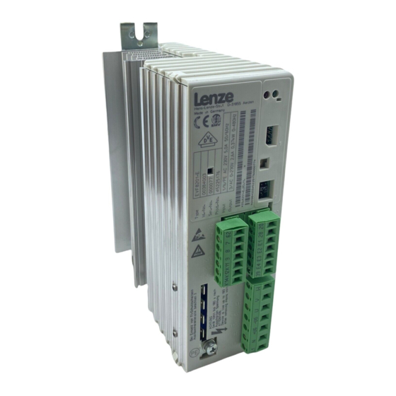
Я так понял, что панель управления у Вас есть?! Инструкция в инете есть, — правда за нее просят ввести номер телефона … Наберите в поисковике Lenze EVF8201-E и будет Вам «щасье». А подключение «силовой» части на всех «частотниках» стандартизировано — VUW к двигателю. L1-N к 220V, L1-L2-L3 к 380V. Вот управление отличается.
Поделиться сообщением
Ссылка на сообщение
-
#18
правда за нее просят ввести номер телефона
Вот ну их нафик таких дельцов — документация 100% есть на сайте lenze, либо на lenze-usa.
Бегло глянул, это не оно:
http://src.lenze.com…-0_DE_EN_FR.pdf
http://src.lenze.com…201-8204_EN.pdf
А никто и не тролит. сбросить девайс до заводских настроек. Вот вы завели автомобиль а руля у вас нет — и куда вы поедите
Я поеду на рынок за рулем, вот только мне никто не будет там кричать, что я украл автомобиль без руля.
Изменено пользователем EugenySG
Поделиться сообщением
Ссылка на сообщение
-
#19
Да, 2-я ссылка, — что дохтур прописал.
стр. 4-9 п.4.2.2.3
стр.4-12 п.4.2.3.3 fig4-6
Получается у Lenze стандарт существует(У меня серия 8200 — те-же обозначения клемм и схема подключения).
Но панель управления(руль  ) все же нужна.
Удачи в подключении!
Поделиться сообщением
Ссылка на сообщение
-
#20
Спасибо всем откликнувшимся
Поделиться сообщением
Ссылка на сообщение
-
#21
Здравствуйте . Вернулся опять к старой теме . Как ни пытался запустить частотник никак не хотит включаться. Параметры в меню выставил все по книжечке а включаться не хотит . Мигает зелёная лампочка , в мануале говорится надо снять блокировку , так как описано ничего не выходит . Может кто подскажет что делать ? Какие вообще клеммы надо замкнуть чтобы он пустился ? Заранее благодарен.
Здравствуйте . Вернулся опять к старой теме . Как ни пытался запустить частотник никак не хотит включаться. Параметры в меню выставил все по книжечке а включаться не хотит . Мигает зелёная лампочка , в мануале говорится надо снять блокировку , так как описано ничего не выходит . Может кто подскажет что делать ? Какие вообще клеммы надо замкнуть чтобы он пустился ? Заранее благодарен.
Поделиться сообщением
Ссылка на сообщение
-
#22
Если есть порт связи с компьютером, то можно и без самого пульта настроить.
Поделиться сообщением
Ссылка на сообщение
-
#23
Wagner_POMA, Роман. Вы запустили частотник? Я долго мучился. Получилось только когда соединил клеммы вот таким образом. (подсмотрел на работе) И он заработал. Правда только на той частоте которую запрограммировал.
Забыл добавить. клеммы 20-28 включение. Когда они замкнуты, привод вращается, соединяем 20-е1,е2,е3 то будут включаться фиксированные скорости
Изменено пользователем бризовец
Поделиться сообщением
Ссылка на сообщение
-
#24
Роман. Вы запустили частотник? Я долго мучился.
И чего мучатся? Пост #17 смотрели?
Поделиться сообщением
Ссылка на сообщение
-
#25
Попробуйте соеденить как в посту 17.
Поделиться сообщением
Ссылка на сообщение
- Назад
- 1
- 2
- 3
- 4
- 5
- 6
- Далее
- Страница 1 из 7
Для публикации сообщений создайте учётную запись или авторизуйтесь
Вы должны быть пользователем, чтобы оставить комментарий
Войти
Уже есть аккаунт? Войти в систему.
Войти
-
Последние посетители
0 пользователей онлайн
Ни одного зарегистрированного пользователя не просматривает данную страницу