- Manuals
- Brands
- ATEN Manuals
- Extender
- CE250a
- User manual
-
Contents
-
Table of Contents
-
Troubleshooting
-
Bookmarks
Quick Links
KVM Extender
CE250
A
User Manual
www.aten.com
Related Manuals for ATEN CE250a
Summary of Contents for ATEN CE250a
-
Page 1
KVM Extender CE250 User Manual www.aten.com… -
Page 2: Fcc Information
CE250 User Manual FCC Information This is an FCC Class A product. In a domestic environment this product may cause radio interference in which case the user may be required to take adequate measures. This equipment has been tested and found to comply with the limits for a Class A digital device, pursuant to Part 15 of the FCC Rules.
-
Page 3: User Information
CE250 User Manual User Information Online Registration Be sure to register your product at our online support center: International http://support.aten.com North America ATEN TECH http://www.aten-usa.com/product_registration ATEN NJ http://support.aten.com Telephone Support For telephone support, call this number: International 886-2-8692-6959 North America…
-
Page 4: Package Contents
© Copyright 2007 ATEN® International Co., Ltd. Manual Part No. PAPE-0222-1ATG Printing Date: 12/2007 ATEN and the ATEN logo are registered trademarks of ATEN International Co., Ltd. All rights reserved. All other brand names and trademarks are the registered property of their respective owners.
-
Page 5: Table Of Contents
CE250 User Manual Contents FCC Information ……….ii RoHS.
-
Page 6
CE250 User Manual Appendix Safety Instructions ……… . 17 General . -
Page 7: About This Manual
CE250 User Manual About this Manual This User Manual is provided to help you get the most from your system. It covers all aspects of installation, configuration and operation. An overview of the information found in the manual is provided below. Chapter 1, Introduction, introduces you to the CE250 system.
-
Page 8: Conventions
For information about all ATEN products and how they can help you connect without limits, visit ATEN on the Web or contact an ATEN Authorized Reseller. Visit ATEN on the Web for a list of locations and telephone numbers: International http://www.aten.com…
-
Page 9: Introduction
Chapter 1 Introduction Overview The CE250 KVM Extender allows access to a computer system from a remote console (keyboard, monitor, and mouse). It is perfect for factory and construction sites, or any type of installation where the console needs to be in a conveniently accessible location, but you want the system equipment to reside in a safe place –…
-
Page 10: Features
CE250 User Manual Features Cat 5 (or higher) cable to connect the Local and Remote Units – up to 150 m apart Dual console operation – control your system from both the local and remote PS/2 keyboard, mouse and monitor consoles Pushbutton selection of the active console High resolution video –…
-
Page 11: Requirements
Chapter 1. Introduction Requirements Console A VGA, SVGA, or Multisync monitor capable of the highest resolution that you will be using on any computer in the installation A PS/2 keyboard A PS/2 mouse Note: 1. If you connect a DDC type monitor to the Local Unit, the monitor that connects to the Remote Unit must be able to support the highest video resolution that the DDC monitor can provide.
-
Page 12: Operating Systems
CE250 User Manual Operating Systems Supported operating systems are shown in the table, below: Version Windows 2000 and higher Linux RedHat 7.1 and higher SuSE 9.0 and higher Mandriva (Mandrake) 9.0 and higher UNIX 4.3, 5L (5.2, 5.3) FreeBSD 4.2, 4.5 Novell Netware 6.0 and higher…
-
Page 13: Components
Chapter 1. Introduction Components CE250 (Local Unit) Front View Description Function Grounding The grounding wire (used to ground the unit) attaches here. Terminal KVM Port The KVM cable that links the CE250 to your computer plugs in here. Only KVM cables designed to work with this switch can be used.* Remote LED The Local Unit has two LEDs to indicate the operating status…
-
Page 14: Ce250Ar (Remote Unit) Front View
CE250 User Manual CE250 (Remote Unit) Front View Description Function Grounding The grounding wire (used to ground the unit) attaches here. Terminal On Line LED These LEDs indicate the operating status of the Local and Remote units. See CE250 (Remote Unit),page 16, for Power LED details.
-
Page 15: Ce250Al / Ce250Ar Rear View
Chapter 1. Introduction CE250 / CE250 Rear View Description Function Power Jack The cable from the DC Power Adapter plugs into this jack.* Mouse Port The console mice plug into these ports. Keyboard Port The console keyboards plugs into these ports. Link Port The Cat 5 cable that connects the Remote and Local units plugs into this connector.
-
Page 16
CE250 User Manual This Page Intentionally Left Blank… -
Page 17: Hardware Setup
Chapter 2 Hardware Setup 1. Important safety information regarding the placement of this device is provided on page 17. Please review it before proceeding. 2. Make sure that power to all the devices you will be installing has been turned off. You must unplug the power cords of any computers that have the Keyboard Power On function.
-
Page 18
CE250 User Manual 2. Use the screws you just removed to attach the mounting bracket that came with your package to the unit: 3. Screw the bracket into any convenient location on the rack. -
Page 19: Installation
Chapter 2. Hardware Setup Installation Grounding To prevent damage to your installation it is important that all devices are properly grounded. 1. Use the two grounding wires supplied with this package to ground both units by connecting one end of the wire to the grounding terminal, and the other end of the wire to a suitable grounded object.
-
Page 20
CE250 User Manual (Continued from previous page.) 4. For increased grounding protection, use STP (shielded twisted pair) cable to connect the local and remote units. There are two methods that can be used: a) In addition to the eight paired wires, STP cable also contains a grounding wire. -
Page 21: Connecting Up
Chapter 2. Hardware Setup Connecting Up Refer to the installation diagram on the following page (the numbers in the diagram correspond to the numbers of the steps), as you perform these steps: 1. Plug the cables from the local console devices (keyboard, monitor, mouse), into their ports on the rear panel of the Local Unit (CE250 2.
-
Page 22
CE250 User Manual CE-250AL CE-250AL CE-250AR… -
Page 23: Operation
Chapter 3 Operation Operating Modes The CE250 KVM Extender has two operating modes: Local and Remote, as described in the table below: Mode Description Local Only the local console has KVM (keyboard, video, mouse) access. The remote console’s monitor is blank, and the remote console’s keyboard and mouse input is disabled.
-
Page 24: Led Display
CE250 User Manual LED Display The CE250 Local and Remote Units have front panel LEDs to indicate their operating status, as shown in the tables, below: CE250 (Local Unit) Operating Mode Local Auto Local Lights to indicate Lights when the local console is active (the Remote that the local LED is out).
-
Page 25: Appendix
Appendix Safety Instructions General Read all of these instructions. Save them for future reference. Follow all warnings and instructions marked on the device. Do not place the device on any unstable surface (cart, stand, table, etc.). If the device falls, serious damage will result. Do not use the device near water.
-
Page 26
CE250 User Manual extension cord ampere rating. Make sure that the total of all products plugged into the wall outlet does not exceed 15 amperes. To help protect your system from sudden, transient increases and decreases in electrical power, use a surge suppressor, line conditioner, or un-interruptible power supply (UPS). -
Page 27: Technical Support
Online Technical Support http://support.aten.com Support Troubleshooting http://www.aten.com Documentation Software Updates Telephone Support 886-2-8692-6959 North America Email Support ATEN TECH support@aten-usa.com ATEN NJ sales@aten.com Online Technical Support ATEN TECH http://www.aten-usa.com/support Support ATEN NJ http://support.aten.com Troubleshooting ATEN TECH http://www.aten-usa.com Documentation ATEN NJ http://www.aten.com…
-
Page 28: Specifications
CE250 User Manual Specifications Function CE250 CE250 Console Selection 1 x Pushbutton Connectors Console Ports 1 x 6-pin Mini-DIN F (Purple) Video 1 x HDB-15 F Mouse 1 x 6-pin Mini-DIN F (Green) KVM Ports 1 x SPHD-15 F Power 1 x DC Jack Unit to Unit 1 x RJ-45…
-
Page 29: Tp Wiring Diagram And Pin Assignments
Appendix TP Wiring Diagram and Pin Assignments PAIR 3 Assignment /V OUT B PAIR 2 PAIR 1 PAIR 4 V OUT B /V OUT G 1 2 3 4 5 6 /V OUT R W-O O W-G Bl W-Bl G W-Br Br V OUT R JACK POSITIONS V OUT G…
-
Page 30: Limited Warranty
CE250 User Manual Limited Warranty IN NO EVENT SHALL THE DIRECT VENDOR’S LIABILITY EXCEED THE PRICE PAID FOR THE PRODUCT FROM THE DIRECT, INDIRECT, SPECIAL, INCIDENTAL OR CONSEQUENTIAL DAMAGES RESULTING FROM THE USE OF THE PRODUCT, DISK OR ITS DOCUMENTATION. The direct vendor makes no warranty or representation, expressed, implied, or statutory with respect to the contents or use of this documentation, and specially disclaims its quality, performance, merchantability, or fitness for any particular purpose.
-
Page 31
Index Registration, iii Operating Modes, 15 CE250AL Front View, 5 Rear View, 7 Rack mounting, 9 CE250AR Rear View, 7 Front View, 6 Requirements Rear View, 7 Cables, 3 Components, 5 Operating Systems, 4 CE250AL Front View, 5 OS Support, 4 CE250AR Front View, 6 RoHS, ii Rear View, 7…
![]()
- Кабель Cat 5e для соединения локального и удаленного устройств — на расстоянии до 150 м
- Работа с двух консолей – управление системой осуществляется с использованием локальной и удаленной консолей KVM, оснащенных PS/2-клавиатурой, мышью и монитором
- Видео высокого разрешения – до 1280 x 1024, 60 Гц
- Автоматическое управление усилением сигнала – автоматическая регулировка силы сигнала для компенсации расстояния
Удлинитель KVM CE250A идеально подойдет для заводов и строительных площадок или любого типа сооружений, где консоль необходимо расположить в удобном для доступа месте, но при этом вы желаете, чтобы системное оборудование оставалось в безопасном месте, и не подвергалось воздействию пыли, грязи и влиянию суровой среды.
Ключевой особенностью модели CE250A является встроенная защита от статического напряжения 8 кВ и защита от перенапряжения на 2 кВ. Кроме того, в устройстве применяется специальная микросхема ASIC, что гарантирует превосходную надежность и совместимость. Она определяет расстояние до компьютера и автоматически регулирует коэффициент усиления.
Удлинитель KVM CE250A является оптимальным средством доступа к удаленному компьютеру, так как использует компактный и недорогой кабель Cat 5e, обеспечивающий более точное, удобное и надежное информационное соединение.
Комплектация
- 1x Удлинитель KVM CE250AL (локальное устройство)
- 1x Удлинитель KVM CE250AR (удаленное устройство)
- 1x специальный KVM-кабель (1,8 м)
- 1x адаптер питания
- 1x комплект для монтажа
- 1x руководство пользователя
- 1x информационная карточка по заземлению
- Кабель Cat 5e для соединения локального и удаленного устройств — на расстоянии до 150 м
- Работа с двух консолей – управление системой осуществляется с использованием локальной и удаленной консолей KVM, оснащенных PS/2-клавиатурой, мышью и монитором
- Активная консоль выбирается с помощью кнопки
- Видео высокого разрешения – до 1280 x 1024, 60 Гц
- Поддержка широкоформатных экранов *
- Поддержка мониторов VGA, SVGA и Multisync – локальный монитор поддерживает DDC; DDC2; DDC2B
- Поддержка мышей Microsoft Intellimouse и колесика на большинстве мышей
- Автоматическое управление усилением сигнала – автоматическая регулировка силы сигнала для компенсации расстояния
- Встроенная защита от статического напряжения 8 кВ и защита от перенапряжения на 2 кВ
- Локальное устройство питается от компьютера — внешнее питание требуется только если для системы KVM не хватается питания локального компьютера/компьютеров
- Возможность монтажа в системную стойку
- Поддержка различных платформ: Поддержка ОС: Windows 2000/XP/Vista и Linux.
* Данные EDID (EDID data) для широкоэкранных мониторов передаются через локальный порт для вывода видео. Для работы с широкоэкранными режимами и мониторами, подсоедините монитор к локальному порту для вывода видео или воспользуйтесь ATEN EDID эмулятором.
| Function | CE250AL | CE250AR |
| Выбор консоли | Нажимная кнопка — 1 шт. | Нажимная кнопка — 1 шт. |
| Разъемы | ||
| Порты консоли | 6-контактное гнездо Mini-DIN (сиреневого цвета) — 1 шт. Гнездо HDB-15 (синего цвета) — 1 шт. 6-контактное гнездо Mini-DIN (зеленого цвета) — 1 шт. |
6-контактное гнездо Mini-DIN (сиреневого цвета) — 1 шт. Гнездо HDB-15 (синего цвета) — 1 шт. 6-контактное гнездо Mini-DIN (зеленого цвета) — 1 шт. |
| KVM порты | Гнездо SPHD-15 — 1 шт. | Нет |
| Питание | Разъем для подключения источника постоянного тока — 1 шт. | Разъем для подключения источника постоянного тока — 1 шт. |
| От устройства к устройству | Гнездо RJ45 (черного цвета) — 1 шт. | Гнездо RJ45 (черного цвета) — 1 шт. |
| Светодиодные индикаторы | ||
| Локальный | 1 (Зеленого цвета) | Нет |
| Дистанционный | 1 (Зеленого цвета) | Нет |
| Питание | Нет | 1 (Зеленого цвета) |
| В сети | Нет | 1 (Зеленого цвета) |
| Эмуляция | ||
| Клавиатура/ Мышь | PS/2 | PS/2 |
| Видео | 1280 x 1024 при 60 Гц (150 м) DDC; DDC2; DDC2B |
1280 x 1024 при 60 Гц (150 м) DDC; DDC2; DDC2B |
| Энергопотребление | DC5V:0.62W:7BTU | DC5V:1.21W:10BTU |
| Температура и влажность | ||
| Рабочая температура | 0~50˚C | 0~50˚C |
| Температура хранения | -20~60˚C | -20~60˚C |
| Влажность | 0~80% рт. ст. | 0~80% рт. ст. |
| Физические свойства | ||
| Корпус | Металлический | Металлический |
| Масса | 0.33 kg ( 0.73 lb ) | 0.32 kg ( 0.7 lb ) |
| Размеры (Д х Ш х В) | 12.70 x 8.66 x 2.63 cm (5 x 3.41 x 1.04 in.) |
12.70 x 8.15 x 2.63 cm (5 x 3.21 x 1.04 in.) |
| Примечание | Обратите внимание, что для некоторых изделий монтируемых стойку, физические размеры (ШxГxВ) выражаются в формате (ДxШxВ). |
Практические примеры применения

CE250A
PS/2, VGA, КВМ-удлинитель по кабелю Cat 5 (1280×1024@150м)
Quick Start Guide
KVM Extender
© Copyright 2012 ATEN
®
International Co., Ltd.
ATEN and the ATEN logo are trademarks of ATEN International Co., Ltd. All rights reserved. All other
trademarks are the property of their respective owners.
This product is ROHS compliant.
Part No. PAPE-1223-204G
Printing Date: 09/2012
CE250
A
KVM Extender Quick Start Guide
Guide de mise en route du système CE250
A
KVM Extender
CE250
A
KVM-Verlängerung Kurzanleitung
Sistema de extensión KVM CE250
A
Guía rápida
CE250
AL
(Local Unit)
CE250
A
Front View
A
CE250
AL
(Local Unit)
1.
Grounding Terminal
2.
KVM Port
3.
Remote LED
4.
Local LED
5.
Operating Mode Selection Switch
CE250
AR
(Remote Unit)
1.
Grounding Terminal
2.
On line LED
3.
Power LED
Rear View
B
CE250
AL
/CE250
AR
1.
Power Jack
2.
Mouse Port
3.
Keyboard Port
4.
Link Port
5.
Video Port
System Requirements:
Console
• A VGA, SVGA, or Multisync monitor capable of the highest resolution that you will be using
on any computer in the installation
• A PS/2 style keyboard
• A PS/2 style mouse
Computers
The following equipment must be installed on each computer that is to be connected to the
system:
• A VGA, SVGA, or Multisync card
• A 6-pin mini-DIN mouse port
• A 6-pin mini-DIN Keyboard port
Operating Systems
• Windows 2000 and higher
• Redhat 7.1 and higher; Mandrake/Mandriva 9.0 and higher
• SuSE 9.0 and higher
• AIX 4.3, 5L (5.2, 5.3) and higher
• FreeBSD 4.2, 4.5 and higher
• Netware 6.0 and higher
• OS/2 Warp and higher
Hardware Installation
Grounding
To prevent damage to your installation it is important that all devices are properly grounded.
Refer to the user manual for grounding procedures.
Connecting Up
C
Refer to the installation diagram (the numbers in the diagram correspond to the numbers of
the steps) as you perform these steps:
1. Plug the cables from the local console devices, into their ports on the rear panel of the
Local Unit (CE250
AL
).
2. Plug the SPHD end of the KVM cable supplied with this unit into the KVM port on the front
panel of the CE250
AL
.
Note:
The shape and function of the connectors on the cable and KVM switch have been
modified so that only KVM cables designed to work with this switch can be used.
3. Plug the connectors on the other end of the cable into the appropriate ports on the
computer (or Console section of the KVM switch — if you are using one). Each connector is
marked with an appropriate icon to indicate itself.
4. Plug one end of a Cat 5 cable into the CE250
AL
‘s Remote I/O port. Plug the other end of
the cable into the CE250
AR
’s Remote I/O port.
Note:
Cat 5 cable is not supplied with this package. It requires a separate purchase. The
cable length can be up to 150 m (500′).
5. Plug the cables from the remote console devices (keyboard, monitor, and mouse), into
their ports on the Console side of the CE250
AR
.
6. Plug the power adapter (supplied with this package) into an AC source; plug the adapter’s
power cable into the CE250
AR
‘s (Remote Unit) Power Jack.
7. If you choose to use a power adapter with the CE250
AL
, plug the power adapter into an AC
source; plug the adapter’s power cable into the CE250
AL
‘s Power Jack.
Note:
Use of a power adapter with the CE250
AL
is optional. The Local unit (CE250
AL
) can
get its power from the computer – external power is only required when the power
from the local computer/computers in the KVM installation is insufficient.
Operation
Operating Modes
The CE250
A
KVM Extender has two operating modes:Local, and Remote, as described in the
table below:
Mode Selection
The Operating Mode Selection Switch, located on the CE250
AL
’s front panel, controls the
operating mode of the CE250
A
KVM Extender system. Pressing the switch toggles the
CE250
A
between Local and Remote operating modes.
Mode
Description
Local
Only the local console has access. The remote console’s monitor
is blank, and the remote console’s keyboard and mouse input is
disabled.
Local / Remote
Both the local and remote consoles can have KVM access.
However, they cannot both have access at the same time. The
console without access has to wait until the console with access
stops inputting data before it can gain access.
CE250
AR
(Remote Unit)
Vue avant
A
CE250
AL
(unité locale)
1.
Borne de terre
2.
Port KVM
3.
Voyant de connexion distante (Remote)
4.
Voyant de connexion locale (Local)
5.
Bouton de sélection du mode de fonctionnement
CE250
AR
(unité distante)
1.
Borne de terre
2.
Voyant de connexion en ligne (On Line)
3.
Voyant d’alimentation (Power)
Vue arrière
B
CE250
AL
/CE250
AR
1.
Prise d’alimentation
2.
Port souris
3.
Port clavier
4.
Port de liaison
5.
Port vidéo
Configuration système
Console
• Un moniteur VGA, SVGA ou Multisync prenant en charge la plus haute résolution à utiliser
sur les ordinateurs à installer
• Un clavier PS/2
• Une souris PS/2
Ordinateurs
Les composants suivants doivent être installés sur chaque ordinateur à connecter au système :
• Une carte VGA, SVGA ou Multisync
• Un port souris mini-DIN à 6 broches
• Un port clavier mini-DIN à 6 broches
Systèmes d’exploitation
• Windows 2000 ou supérieur
• Redhat 7.1 ou supérieur ; Mandrake/Mandriva 9.0 ou supérieur
• SuSE 9.0 ou supérieur
• AIX 4.3, 5L (5.2, 5.3)
• FreeBSD 4.2, 4.5
• Netware 6.0 ou supérieur
• OS/2 Warp ou supérieur
Installation du matériel
Borne
Afin d’éviter d’endommager votre installation, vérifiez que tous les périphériques sont
correctement reliés à la terre. Pour plus d’informations sur les procédures de mise à la terre,
consultez le manuel d’utilisation.
Installation
C
Reportez-vous au schéma de connexion (les numéros du schéma correspondent aux
numéros des étapes ci-dessous) en procédant comme suit :
1. Branchez les câbles des périphériques de console locaux sur les ports respectifs situés à
l’arrière de l’unité locale CE250
AL
.
2. Branchez l’extrémité SPHD du câble KVM fourni avec cette unité sur le port KVM situé à
l’avant de l’unité locale CE250
AL
.
Remarque :
la forme et la fonction des connecteurs du câble et du commutateur KVM
ont été modifiées de façon à ce que seuls les câbles KVM conçus pour
fonctionner avec ce commutateur puissent être utilisés.
3. Branchez les connecteurs de l’autre extrémité du câble sur les ports respectifs de
l’ordinateur (ou de la partie console du commutateur KVM, si vous en utilisez un). Chaque
connecteur est associé à une icône spécifique permettant de le distinguer facilement.
4. Branchez une extrémité du câble de catégorie 5 sur le port Remote I/O (E/S distantes)
de l’unité locale CE250
AL
. Branchez l’autre extrémité du câble sur le port Remote I/O de
l’unité distante CE250
AR
.
Remarque :
le câble de catégorie 5 n’est pas fourni avec ce produit. Il doit être acheté
séparément et ne doit pas mesurer plus de 150 m.
5. Branchez les câbles des périphériques de console distants (clavier, moniteur et souris) sur
les ports respectifs de la partie console de l’unité distante CE250
AR
.
6. Connectez une extrémité du câble de l’adaptateur secteur fourni à une prise de courant, et
l’autre extrémité à la prise d’alimentation de l’unité distante CE250
AR
(unité distante).
7. Si vous souhaitez utiliser un adaptateur secteur avec l’unité locale CE250
AL
, connectez
une extrémité du câble de l’adaptateur à une prise de courant, et l’autre extrémité à la
prise d’alimentation de l’unité locale CE250
AL
.
Remarque :
l’utilisation d’un adaptateur secteur avec l’unité locale CE250
AL
est
facultative. L’unité locale (CE250
AL
) peut être alimentée par l’ordinateur. Une
alimentation externe est uniquement nécessaire si l’alimentation fournie par
le ou les ordinateurs locaux de l’installation KVM est insuffisante.
Utilisation
Modes de fonctionnement
Mis à part le mode le système CE250
A
KVM Extender offre deux modes de fonctionnement :
Local (connexion locale) et Remote (connexion distante), décrits dans le tableau ci-dessous :
Sélection du mode
Le bouton de sélection du mode de fonctionnement, situé à l’avant de l’unité locale CE250
AL
,
contrôle le mode de fonctionnement du système CE250
A
KVM Extender. Appuyez sur ce
bouton pour basculer entre les modes de fonctionnement Local et Remote du système
CE250
A
.
Mode
Description
Local
Seule la console locale y a accès. Rien ne s’affiche sur l’écran de
la console distante, et l’entrée de son clavier et de sa souris est
désactivée.
Local /Remote
La console locale comme la console distante peuvent avoir le
contrôle KVM. Elles ne peuvent toutefois pas l’avoir en même temps.
Avant d’y avoir accès, la console n’ayant pas le contrôle doit patienter
jusqu’à ce que celle ayant le contrôle cesse d’entrer des données.
Vorderseitige Ansicht
A
CE250
AL
(lokales Gerät)
1.
Erdungsanschluss
2.
KVM-Port
3.
Remote-LED
4.
Local-LED
5.
Betriebsmodus-Auswahlschalter
CE250
AR
(Gerät für Gegenstelle)
1.
Erdungsanschluss
2.
Online-LED
3.
LED-Betriebsanzeige
Rückseitige Ansicht
B
CE250
AL
/CE250
AR
1.
Stromeingangsbuchse
2.
Mausanschluss
3.
Tastaturanschluss
4.
Verbindungs-Port
5.
Grafikeingang
Systemvoraussetzungen
Konsole
• Ein VGA-, SVGA- oder Multisync-Monitor, der in der Lage ist, die höchste Auflösung
darzustellen, die Sie auf einem der zu installierenden Computer verwenden möchten
• Eine PS/2-Tastatur
• Eine PS/2-Maus
Computer
Auf den Computern, die mit dem System verbunden werden sollen, muss mindestens
Folgendes installiert sein:
• Eine VGA-, SVGA- oder Multisync-Grafikkarte
• Ein 6-poliger Mini-DIN-Mausport
• Ein 6-poliger Mini-DIN-Tastaturport
Betriebssysteme
• Windows 2000 oder höher
• Redhat 7.1 oder höher; Mandrake/Mandriva 9.0 oder höher
• SuSE 9.0 oder höher
• AIX 4.3, 5L (5.2, 5.3)
• FreeBSD 4.2, 4.5
• Netware 6.0 oder höher
• OS/2 Warp oder höher
Hardware installieren
Um eine Beschädigung Ihrer Geräte zu vermeiden, müssen alle Geräte ordnungsgemäß
geerdet sein. Für weitere Details zur Erdung, siehe das Benutzerhandbuch.
installieren
C
Siehe das Installationsdiagramm (die Zahlen im Diagramm entsprechen der Reihenfolge),
und gehen Sie folgendermaßen vor:
1. Verbinden Sie die Kabel der lokalen Konsolgeräte mit den entsprechenden Buchsen auf
der Rückseite des lokalen Gerätes (CE250
AL
).
2. Verbinden Sie den SPHD-Stecker des mitgelieferten KVM-Kabels mit dem KVM-Port auf
der Vorderseite des CE250
AL
.
Hinweis:
Form und Belegung der Stifte dieses Steckers und KVM-Switches wurden so
hergestellt, dass nur KVM-Kabel angeschlossen werden können, die für diesen
Switch geeignet sind.
3. Verbinden Sie die Stecker am anderen Kabelende mit den betreffenden Anschlüssen
am Computer (oder des Konsolabschnitts des KVM-Switches, wenn Sie einen
solchen verwenden möchten). Jeder Anschluss ist durch ein entsprechendes Symbol
gekennzeichnet.
4. Verbinden Sie ein Ende des Kat. 5-Kabels mit dem Anschluss Remote I/O des CE250
AL
.
Verbinden Sie das andere Ende des Kabels mit dem Anschluss Remote I/O des CE250
AR
.
Hinweis:
Das Kat. 5-Kabel ist nicht im Lieferumfang enthalten. Sie müssen es separat
erwerben. Die Kabellänge darf maximal 150 m betragen.
5. Verbinden Sie die Kabel der Konsolgeräte der Gegenstelle (Maus, Tastatur, Monitor) mit
den entsprechenden Buchsen im Konsolabschnitt des CE250
AR
.
6. Verbinden Sie das mitgelieferte Netzteil mit einer Steckdose und sein Netzkabel mit der
Stromeingangsbuchse des CE250
AR
(Gerät für Gegenstelle).
7. Wenn Sie ein Netzteil für den CE250
AL
verwenden möchten, verbinden Sie dieses mit
einer stromführenden Steckdose, und verbinden Sie das Kabel des Netzteils mit der
Stromeingangsbuchse des CE250
AL
.
Hinweis:
Die Speisung des CE250
AL
über ein Netzteil ist optional. Das lokale Gerät
(CE250
AL
) kann direkt über den Computer gespeist werden – eine externe
Stromversorgung ist nur erforderlich, wenn der lokale Computer bzw. die
Computer aus der KVM-Installation nicht ausreichend Strom zur Verfügung
stellen.
Bedienung
Betriebsmodi
Die CE250
A
KVM-Verlängerung unterstützt zwei Betriebsarten: Lokal und Gegenstelle, siehe
folgende Tabelle:
Betriebsart auswählen
Die Betriebsart-Auswahltaste auf der Vorderseite des CE250
AL
steuert die Betriebsart des
gesamten CE250
A
KVM-Systems. Drücken Sie die Taste, um die Steuerung zwischen den
beiden CE250
A
-Einheiten umzuschalten (lokal und Gegenstelle).
Betriebsart
Beschreibung
Lokal
Nur die lokale Konsole hat Zugriff. Der Monitor der Konsole der
Gegenstelle bleibt dunkel, und Tastatur und Maus der Gegenstelle
sind deaktiviert.
Lokal /
Gegenstelle
Sowohl die lokale als auch die Konsole der Gegenstelle können die
KVM-Steuerung übernehmen. Allerdings können nicht beide Konsolen
gleichzeitig eingesetzt werden. Bevor sie Zugriff erhält, muss die
Konsole ohne Zugriff warten, bis die Konsole mit aktuellem Zugriff die
Dateneingabe stoppt.
Vista frontal
A
CE250
AL
(unidad local)
1.
Terminal de tierra
2.
Puerto KVM
3.
Indicador de conexión remota (Remote)
4.
Indicador de conexión local (Local)
5.
Conmutador del modo operativo
CE250
AR
(unidad remota)
1.
Terminal de tierra
2.
Indicador de conexión en línea (On Line)
3.
Indicador de alimentación (Power)
Vista posterior
B
CE250
AL
/CE250
AR
1.
Entrada de alimentación
2.
Puerto de ratón
3.
Puerto de teclado
4.
Puerto de enlace
5.
Puerto gráfico
Requisitos del sistema
Consola
• Un monitor VGA, SVGA o Multisync capaz de representar la resolución más elevada que
vaya a usar con cualquiera de los ordenadores a instalar
• Un teclado PS/2
• Un ratón PS/2
Ordenadores
En cada ordenador que vaya a conectar al sistema se tienen que instalar los siguientes
componentes:
• Una tarjeta gráfica VGA, SVGA o Multisync
• Un puerto mini-DIN para ratón de 6 patillas
• Un puerto mini-DIN para teclado de 6 patillas
Sistemas operativos
• Windows 2000 o superior
• Redhat 7.1 o superior; Mandrake/Mandriva 9.0 o superior
• SuSE 9.0 o superior
• AIX 4.3, 5L (5.2, 5.3)
• FreeBSD 4.2, 4.5
• Netware 6.0 o superior
• OS/2 Warp o superior
Instalación del hardware
Conexión a tierra
Para evitar daños en los dispositivos, verifique que todos ellos estén conectados a tierra
correctamente. Consulte el manual de usuario para más información sobre la conexión a
tierra.
Instalación
C
Véase el diagrama de instalación (los números en el diagrama equivalen a los números de
los pasos a seguir) y proceda como se indica a continuación:
1. Conecte los cables de los dispositivos de la consola local a los puertos respectivos
situados en el panel posterior de la unidad local CE250
AL
.
2. Conecte el extremo SPHD del cable KVM que viene con esta unidad al puerto KVM
situado en el panel frontal de la unidad local CE250
AL
.
Nota:
la forma y la función de los conectores del cable y del conmutador KVM han sido
modificadas de manera que sólo se puedan utilizar los cables KVM diseñados para
funcionar con este conmutador.
3. Enchufe los conectores del otro extremo del cable a los puertos respectivos del ordenador
(o a la sección de consola del concentrador KVM en caso de que desee utilizar una).
Cada conector viene marcado con un icono correspondiente.
4. Conecte un extremo del cable de Cat. 5 al puerto Remote I/O de la unidad local CE250
AL
.
Conecte el otro extremo del cable al puerto Remote I/O de la unidad remota CE250
AR
.
Nota:
el cable de Cat. 5 no está incluido en el paquete. Deberá adquirirlo por separado.
Su longitud máxima puede ser de 150 m.
5. Conecte los cables de los dispositivos de la consola remota (teclado, monitor y ratón) a
los puertos de consola respectivos de la unidad remota CE250
AR
.
6. Conecte un extremo del cable del adaptador de alimentación incluido a una toma eléctrica
y el otro extremo a la entrada de alimentación de la unidad remota CE250
AR
(unidad
remota).
7. Si desea utilizar un adaptador de alimentación con la unidad local CE250
AL
, conecte un
extremo del cable de adaptador a una toma eléctrica y el otro extremo a la entrada de
alimentación de la unidad local CE250
AL
.
Nota:
el uso de un adaptador de alimentación con la unidad local CE250
AL
es opcional.
Se puede alimentar la unidad local (CE250
AL
) mediante el ordenador. Una
alimentación externa sólo es necesaria si la alimentación suministrada por el o los
ordenadores locales de la instalación KVM es insuficiente.
Funcionamiento
Modos operativos
Aparte del modo el sistema de extensión KVM CE250
A
ofrece dos modos operativos: Local
(conexión local) y Remote (conexión remota), que se describen en la siguiente tabla:
Selección de modo
El conmutador del modo operativo, situado en el panel frontal de la unidad local CE250
AL
,
controla el modo operativo del sistema de extensión KVM CE250
A
. Pulse este botón para
alternar entre los modos operativos Local y Remota del sistema CE250
A
.
Modo
Descripción
Local
Sólo la consola local tiene acceso. No aparece nada en el monitor de
la consola remota, y su teclado y ratón están desactivados.
Local /Remote
Tanto la consola local como la remota pueden tener el control KVM.
Sin embargo, no lo pueden tener al mismo tiempo. Antes de conseguir
el acceso, la consola que no tiene el control KVM debe esperar hasta
que la consola que lo tiene deje de entrar datos.
www.aten.com
www.aten.com
www.aten.com
www.aten.com
Important Notice
Considering environmental protection, ATEN does not
provide a fully printed user manual for this product. If
the information contained in the Quick Start Guide is not
enough for you to configure and operate your product,
please visit our website www.aten.com, and download the
full user manual.
Online Registration
http://eservice.aten.com
Technical Phone Support
International:
886-2-86926959
North America:
1-888-999-ATEN Ext: 4988
United Kingdom:
44-8-4481-58923
Package Contents
1 CE250AL KVM Extender (Local Unit)
1 CE250AR KVM Extender (Remote Unit)
1 Custom KVM Cable (1.8 m)
1 Power Adapter
1 Mounting Kit
1 User Instructions
Rear View
(CE250
AL
/ CE250
AR
)
B
1
2
3
4
5
C
CE250
AR
CE250
AL
4
1
7
4
6
1
1
5
5
5
(Optional)
CE250
AL
2
3
All information, documentation, and specifications
contained in this media are subject to change without
prior notification by the manufacturer. Please visit our
website to find the most up to date version.
A
Front View
2
3
4
5
1
2
3
1
-
Инструкции по эксплуатации
1

Aten CE250A инструкция по эксплуатации
(30 страниц)
- Языки:Английский
-
Тип:
PDF -
Размер:
971.07 KB
Просмотр
На NoDevice можно скачать инструкцию по эксплуатации для Aten CE250A. Руководство пользователя необходимо для ознакомления с правилами установки и эксплуатации Aten CE250A. Инструкции по использованию помогут правильно настроить Aten CE250A, исправить ошибки и выявить неполадки.
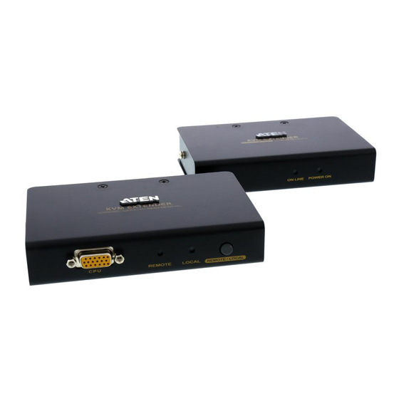
ATEN CE250A — PS/2, VGA, KVM Удлинитель, 150м., по витой паре, Cat 5e
CE250A-A7-G – KVM
Удлинитель ATEN CE250A , обеспечивающий пользователям доступ к компьютеру (или KVM-переключателю)
с консоли (клавиатура, монитор и мышь), удаленной на 150м. Модель состоит из удаленного и локального модулей,
соединяемых кабелем витая пара категории 5 (или более высокой).
Удлинитель CE250A является оптимальным
средством доступа к удаленному компьютеру, так как использует компактный и недорогой кабель «витая пара» Cat 5e,
обеспечивающий простое и надежное соединение.
Удлинитель KVM CE250A идеально подойдет для заводов и
строительных площадок или любого типа сооружений, где консоль необходимо расположить в удобном для доступа месте, но при
этом вы желаете, чтобы системное оборудование оставалось в безопасном месте, и не подвергалось воздействию пыли, грязи и
влиянию суровой среды.
Ключевой особенностью модели CE250A является встроенная защита от статического
напряжения 8 кВ и защита от перенапряжения на 2 кВ. Кроме того, в устройстве применяется специальная микросхема ASIC,
что гарантирует превосходную надежность и совместимость. Она определяет расстояние до компьютера и автоматически
регулирует коэффициент усиления.
Характеристики ATEN CE250A:
- Кабель Cat 5e для соединения локального и удаленного устройств — на расстоянии до 150 м
- Работа с двух консолей – управление системой осуществляется с использованием локальной и удаленной консолей
KVM, оснащенных PS/2-клавиатурой, мышью и монитором - Активная консоль выбирается с помощью кнопки
- Видео высокого разрешения – до 1280 x 1024, 60 Гц
- Поддержка широкоформатных экранов *
- Поддержка мониторов VGA, SVGA и Multisync – локальный монитор поддерживает DDC; DDC2; DDC2B
- Поддержка мышей Microsoft Intellimouse и колесика на большинстве мышей
- Автоматическое управление усилением сигнала – автоматическая регулировка силы сигнала для компенсации
расстояния - Встроенная защита от статического напряжения 8 кВ и защита от перенапряжения на 2 кВ
- Локальное устройство питается от компьютера — внешнее питание требуется только если для системы KVM не
хватается питания локального компьютера/компьютеров - Возможность монтажа в системную стойку
- Поддержка различных платформ: Поддержка ОС: Windows 2000/XP/Vista и Linux.
* Данные EDID (EDID data) для широкоэкранных мониторов передаются через локальный порт для вывода видео. Для
работы с широкоэкранными режимами и мониторами, подсоедините монитор к локальному порту для вывода видео или
воспользуйтесь ATEN EDID эмулятором.
Спецификация ATEN CE250A-A7-G
| Function | CE250AL | CE250AR |
| Выбор консоли | Нажимная кнопка — 1 шт. | Нажимная кнопка — 1 шт. |
| Разъемы | ||
| Порты консоли | 6-контактное гнездо Mini-DIN (сиреневого цвета) — 1 шт. Гнездо HDB-15 (синего цвета) — 1 шт. 6-контактное гнездо Mini-DIN (зеленого цвета) — 1 шт. |
6-контактное гнездо Mini-DIN (сиреневого цвета) — 1 шт. Гнездо HDB-15 (синего цвета) — 1 шт. 6-контактное гнездо Mini-DIN (зеленого цвета) — 1 шт. |
| KVM порты | Гнездо SPHD-15 — 1 шт. | Нет |
| Питание | Разъем для подключения источника постоянного тока — 1 шт. | Разъем для подключения источника постоянного тока — 1 шт. |
| От устройства к устройству | Гнездо RJ45 (черного цвета) — 1 шт. | Гнездо RJ45 (черного цвета) — 1 шт. |
| Светодиодные индикаторы | ||
| Локальный | 1 (Зеленого цвета) | Нет |
| Дистанционный | 1 (Зеленого цвета) | Нет |
| Питание | Нет | 1 (Зеленого цвета) |
| В сети | Нет | 1 (Зеленого цвета) |
| Эмуляция | ||
| Клавиатура/ Мышь | PS/2 | PS/2 |
| Видео | 1280 x 1024 при 60 Гц (150 м) DDC; DDC2; DDC2B |
1280 x 1024 при 60 Гц (150 м) DDC; DDC2; DDC2B |
| Энергопотребление | DC5V:0.62W:7BTU | DC5V:1.21W:10BTU |
| Температура и влажность | ||
| Рабочая температура | 0~50˚C | 0~50˚C |
| Температура хранения | -20~60˚C | -20~60˚C |
| Влажность | 0~80% рт. ст. | 0~80% рт. ст. |
| Физические свойства | ||
| Корпус | Металлический | Металлический |
| Масса | 0.33 kg ( 0.73 lb ) | 0.32 kg ( 0.7 lb ) |
| Размеры (Д х Ш х В) | 12.70 x 8.66 x 2.63 cm (5 x 3.41 x 1.04 in.) |
12.70 x 8.15 x 2.63 cm (5 x 3.21 x 1.04 in.) |
| Примечание | Обратите внимание, что для некоторых изделий монтируемых стойку, физические размеры (ШxГxВ) выражаются в формате (ДxШxВ). |
Комплектация
1x Удлинитель KVM CE250AL (локальное устройство)
1x Удлинитель KVM CE250AR
(удаленное устройство)
1x специальный KVM-кабель (1,8 м)
1x адаптер питания
1x комплект для монтажа
1x
руководство пользователя
1x информационная карточка по заземлению
Задать вопрос
Вы можете задать любой интересующий вас вопрос по товару или работе магазина.
Наши квалифицированные специалисты обязательно вам помогут.
Оформить заказ на нашем сайте легко. Просто добавьте выбранные товары в корзину, а затем перейдите на страницу Корзина, проверьте правильность заказанных позиций и нажмите кнопку «Оформить заказ».
Этапы на странице оформления заказа:
❶ Выбор типа покупателя (физическое или юр. лицо)
❷ Выбор местоположения (определяется автоматически, можно изменить)
❸ Выбор способа доставки (курьерские службы, самовывоз)
❹ Выбор способа оплаты (онлайн картой на сайте или счет для юр. лиц)
❺ Данные покупателя (ФИО, адрес доставки, телефон, e-mail)
❻ Подтверждение заказа (проверка данных и оформление покупки)
Оплата заказа юридическими лицами.
При оформлении заказа необходимо указать полные реквизиты компании. После обработки заказа менеджером Вам будет выставлен счет на оплату. Компания оплачивает счет стандартно, банковским переводом.
Оплата заказа физическими лицами.
Оплату банковской картой возможно произвести сразу после оформления заказа, либо из личного кабинета со страницы с вашим заказом.
Оплата происходит моментально и без комиссии. Оплата производится через сервис Яндекс.Касса.
Вся платёжная информация (номер заказа, имя, телефон, эл.почта) защищена и зашифрована сертификатом SSL (протокол https).
Курьерская доставка по Москве
Варианты доставки:
— бесплатно при заказе от 10 000 руб. Доставка осуществляется в пределах МКАД;
— 300 руб. при заказе до 10 000 руб. собственным курьером по указанному адресу в пределах МКАД.
Вы можете заказать доставку товара с помощью курьера. Товар из наличия доставляется на следующий рабочий день с 9.30 до 18.30. Курьерская служба свяжется с вами и предложит выбрать удобное время доставки, уточнит адрес.
Для оформления доставки требуется указать:
- точный адрес доставки;
- ФИО человека, ответственного за прием заказа;
- контактные телефоны;
- наличие и стоимость платного въезда.
Доставки автомобилем осуществляются только до подъезда. Все погрузочно-разгрузочные работы производит покупатель.
Время ожидания до разгрузки не должно превышать 20 минут. Если за это время разгрузка не началась, либо груз не может быть принят по каким либо не зависящим от нас причинам, водитель имеет право уехать с грузом. Услуга по доставке при этом считается выполненной.
На вокзалы, аэропорты, станции метрополитена, в парки, строящиеся объекты, парковки или иные места, которые не имеют точного адреса либо условий для передачи товаров, доставки не совершаются.
Негабаритные грузы и грузы, превышающие по массе 500 кг., доставляются транспортными компаниями. Стоимость такой доставки определяется в зависимости от тарифов выбранной ТК и сложности доставки.
Доставка в регионы России
Варианты доставки:
— По тарифам в ваш регион: СДЭК (курьер, самовывоз), DPD (курьер, самовывоз), Деловые Линии (самовывоз, либо до терминала в Москве). Стоимость доставки рассчитывается автоматически и указывается на странице оформления заказа.
Вы можете заказать доставку в любой регион России:
- до терминала транспортной компании в Вашем или ближайшем к Вам городе;
- до пункта самовывоза;
- до указанного адреса (доставка до двери).
Самовывоз со склада
Вы можете забрать товар с нашего склада после согласования с менеджером. Самовывоз осуществляется по адресу: г. Москва, 2-ой Нагатинский проезд д.2 стр.8, с понедельника по четверг с 10:00 до 18:00, пятница с 10:00 до 17:00. За 10-15 минут до приезда НЕОБХОДИМО предупредить менеджера.
Официальный магазин ATEN предлагает купить Удлинитель ATEN CE250A из раздела «KVM удлинители» каталога «KVM Оборудование» по выгодной цене.
Обращаем ваше внимание, что вся информация, опубликованная на сайте www.atenpro.ru, в том числе стоимость товаров, описание, характеристики и комплектация не является публичной офертой, носит справочный характер и не может расцениваться как коммерческое предложение. Во избежание недоразумений просим уточнять стоимость товара у менеджера.
Список совместимых продуктов и КВМ аксессуаров можно посмотреть ниже в карточке товара в нашем интернет магазине.
При покупке в компании ATENPRO только аксессуаров для KVM переключателей (KVM-кабели, KVM-адаптеры) будьте готовы уточнить модель и серийный номер КВМ оборудования, для которого осуществляется закупка данных аксессуаров.
В случае несовместимости аксессуара с указанным Покупателем КВМ оборудованием, а также при нежелании или невозможности указания модели и серийного номера КВМ, компания ATENPRO оставляет за собой право отказать в продаже аксессуаров.
Производитель оставляет за собой право изменить комплектацию и характеристики продукции без уведомления покупателя.