- Manuals
- Brands
- Kubota Manuals
- Engine
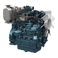
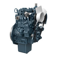
- D1102-B
- Workshop manual
-
Contents
-
Table of Contents
-
Troubleshooting
-
Bookmarks
Quick Links
WORKSHOP MANUAL
DIESEL ENGINES
KiSC issued 09, 2007 A
Related Manuals for Kubota D1102-B
Summary of Contents for Kubota D1102-B
-
Page 1
WORKSHOP MANUAL DIESEL ENGINES D1102-B,D1302-B,D1402-B, V1502-B,V1702-B,V1902-B KiSC issued 09, 2007 A … -
Page 2
• Section V «Service Directions» covers all reference values and allowable limits required for servicing. 0078 P001 KUBOTA Corporation reserves the right to change the specifications without notice. No part of this manual may be reproduced without permission of KUBOTA Corporation. -
Page 3
CONT ENTS SPECIFICATIONS AND PERFORMANCE CURVES ……… 3 Section GENER AL DESCRIPTION …………….13 Section II 1. Engine 2. Lubrication System 3. Cooling System 4. Fuel System 5. Electrical System ENGINE ………………….27 Section 1. Troubleshooting 2. Disassembly and Reassembly 3. -
Page 4
Section SPECIFICATIONS AND PERFORMANCE CURVES » « ;;/. » «‘ • D1102-B ……………………4 • D1302-B ……………………5 ……………………. 6 • D1402-B • V1502-B ……………………7 ……………………. 8 • V1702-B • V1902-B ……………………9 • DIMENSIONS ……………………10 KiSC issued 09, 2007 A… -
Page 5
Section SPECIFICATIONS AND PERFORMANCE CURVES • D1102-B Specifications Model D1102-B Maximum Bare Speed 3000 min· (rpm) Vertical, water-cooled, Minimum Bare Idling Speed 800 min (rpm) Type 4-cycle diesel engine Combustion Chamber Spherical Type Number of Cylinders Fuel Injection Pump Bosch K Type mini pump… -
Page 6
• 01302-B Specifications Model D1302-B Maximum Bare Speed 3000 min- (rpm) Vertical, water-cooled, Minimum Bare Idling Speed 800 min- (rpm) Type 4-cycle diesel engine Combustion Chamber Spherical Type Number of Cylinders Fuel Injection Pump Bosch K Type mini pump Bore x Stroke mm (inch) 82 x 82 L ( 3.23 x 3.23 L) -
Page 7
• 01402-e Specifications Model D1402-B Maximum Bare Speed 3000 min- (rpm) Vertical, water-cooled, Minimum Bare Idling Speed 800 min- (rpm) Type 4-cycle diesel engine Combustion Chamber Spherical Type Number of Cylinders Fuel Injection Pump Bosch K Type mini pump Bore x Stroke mm (inch) 82 L ( 3.25… -
Page 8
• v1so2-e Specifications 3000 min·1(rpm) Model V1502 B Maximum Bare Speed Vertical, water-cooled, Minimum Bare Idling Speed 800 min-1(rpm) Type 4-cycle diesel engine Combustion Chamber Spherical Type Number of Cylinders Fuel Injection Pump Bosch K Type mini pump 2.99 3.23 Bore Stroke mm (inch}… -
Page 9
• V1702-B Specifications Model V1702-B Maximum Bare Speed 3000 min- (rpm) Vertical, water-cooled, Minimum Bare Idling Speed 800 min- (rpm) Type 4-cycle diesel engine Spherical Type Combustion Chamber Number of Cylinders Fuel Injection Pump Bosch K Type mini pump 82 L ( 3.23 3.23 L) Bore x Stroke… -
Page 10
• v1so2-e Specifications Model V1902-B Maximum Bare Speed 3000 min- (rpm) Vertical, water-cooled, Minimum Bare Idling Speed 800 min- (rpm) Type 4-cycle diesel engine Combustion Chamber Spherical Type Number of Cylinders Fuel Injection Pump Bosch K Type mini pump Bore x Stroke mm (inch) q;… -
Page 11
• DIMENSIONS (01101-B, 01302-B, 01402-B) — —- ———- —— —— —— i— — — — 512 mm (20. 16″)- — — — — ….i 257mm (10.12″) — — 580mm (22,83″)-01102-B, 01302-B ——————- i 568mm (22.36″)-01402-B 10mm (0.39″) 240mm (9.45″) i— — — — -544mm (21.42″)1- …… -
Page 12
(V1502-B, V1702-B, V1902-B) 512mm (20.16″) 662mm (26.06″)-V1502-B 257mm 652mm (25.67″)-V1702-B, V1902-B (1012″) 2-08.2 0073F014 KiSC issued 09, 2007 A … -
Page 13
KiSC issued 09, 2007 A … -
Page 14
Section GENEIIAt. DEIGRIPf:101 · · ti> «‘ «: «»‘ » ,,,» .,., FEATURE …………. 14 4. FUEL SYSTEM 1. ENGINE 4.1 Fuel Filter (Optional Part) ……19 1.1 Cylinder Block ….16 4.2 Fuel Pump . -
Page 15
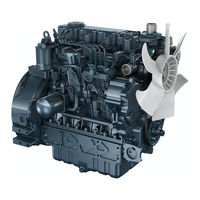
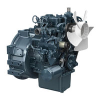
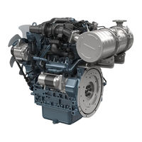
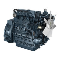
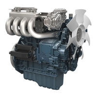
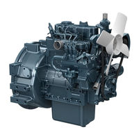
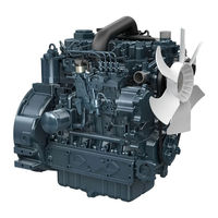
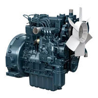
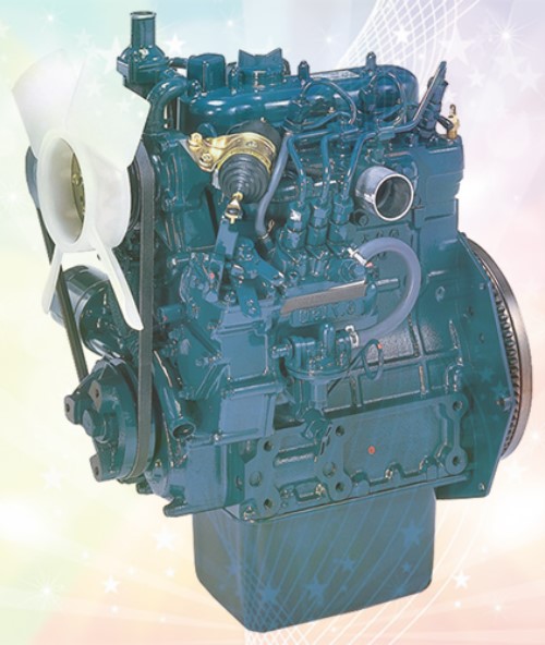
The D 1102-8, 01302-B, D 1402-B, V1502-B, V1702-B, V1902-B are water-cooled, 4-cycle diesel engines, they concentrate Kubota’s foremost technologies. With Kubota’s designed spherical combustion chamber, well-known Bosch K type injection pump, well-balance designs, they feature greater power, low fuel consumption, little vibration limited noise. -
Page 16
KiSC issued 09, 2007 A … -
Page 17
1-1 CYLINDER BLOCK (A) Tunnel Cylinder Block The engi ne f eatu res a h igh d u ra bi l ity tu nnel-ty pe cyl i nder bl ock. F urthermore, d ry-type cyl i nder l i ners a re pressure- fitted i nto cyl i nders a l low ef fective cool i ng, l ess d istort ion, h igher wear-resista nce q ua l ity a nd each cyl i nder has its own cha mber hel ps to m i n i m i ze noise. -
Page 18
and Piston Rings 1-3 PISTON AND PISTON RINGS A piston of special el l i ptic shape is designed i n consideration of explosion heat. Fu rther more, to enha nce piston’s strength , a rib is prov ided between the piston a nd the piston boss. Th ree piston ri ngs a re provided;… -
Page 19
(A) Lubrication System The l u brication system consists of a trochoide rotor-type driven oil pu mp, oil filter cartridge, oil pressure regulati ng valve, oil switch a nd oi l filter. Oil is sucked by the oil pu mp (b) from the oi l pa n (o) through the oil f ilter (a) , a nd the oi l is kept at 294 to 441 kPa (3.0 to 4.5 kgf/cm 42 to 64 psi) by a n oil pressure regulati ng va lve… -
Page 20
(A) Fuel System In operation, fuel from the fuel tank (a) enters the filter (b), (f ) where it is cleaned and absorb- ed by the suction of fuel pump (c). ( V1502-B, V1702-B, V1902-B are available) The pump then pushes it to the injection pump (d), where it is pressurized under high pressure and through the injection pipe… -
Page 21
Discharge Stroke (A) Inlet Stroke 4-2 FUEL PUMP The f uel pu m p sucks the f i ltered f uel a nd, forces it u nder pressu re to the i njection pum p. Suck i ng a nd d ischa rgi ng are done by the vertica l movement of the d ia phragm ( b) , wh ich is operated by a cam of the f uel ca mshaf t (a) . -
Page 22
(A) Pressurization of Fuel How it works: 1 ) When the pl u nger is at the bottom of its stroke, f uel from the f uel cha mber enters the del ivery chamber through the f eed hole ( F ig. As the ca mshaf t rotates, pl u nger moves u pward, the stroke of f uel pressu ri zation begi ns. -
Page 23
(a) Control rack Feed hole Control groove (d) Effective Stroke Fig. 3 (el Effective Stroke maximum 0011F045 KiSC issued 09, 2007 A… -
Page 24
(Al Injection Nozzle 4-4 INJECTION NOZZLE The nozzle is a throttl e-type one, it f eatures l ow f uel con- sum ption a nd works wel l with K u bota’s spherica l combus- tion chamber. The nozzle valve open i ng pressu re is abou t 13.7 to 14.7 MPa (140 to 150 kgf /cm 1990 to 2130 psi) , the pressu re over- comes the cou nterforce of nozzl e val ve spri ng ( b) , and push… -
Page 25
Electrical System 0073F021 (A) N-30 Construction 5-1 CRANK ING SYSTEM The cran ki ng system consists of a battery of 12V, magnet sta rter, glow pl ugs a nd a oi l switch. Starter The magnet-switch ty pe starter is composed of two mai n section. -
Page 26
(A) Starter Circuit 0011F173 (A) When Key Switch is On: How it works: • W hen Key Switch is On: Wh en the key sw itch is tu rned on, a cur rent flows from the battery th rough the pu l l-i n coil i n the magnet sw itch section to the hold i ng coi l , energizi ng the pl u nger to pu l l it i n. -
Page 27
Alternator 5-2 CHARGING SYSTEM The chargi ng system consists of an (f ) (g) (h) AC a l ternator a regu l ator (option). The alternator generates … -
Page 28
KiSC issued 09, 2007 A… -
Page 29
Section 1. TROUBLESHOOTING ….28 3. SERVICING Cylinder Head ….• . . 49 2. -
Page 30
1.TROUBLESHOOTI NG Crankshaft does not turn. No or small fuel injection sounds. Crankshaft turns. Fuel injection sounds. KiSC issued 09, 2007 A … -
Page 31
Reference .—- Cran kshaft and cam shaft have seized u p . 59,63 Piston a nd cy l i nder l i ner have seized u p. Fricti onal resistance of movi ng 62,68 ..,.. parts is too m uch. Bea ri ngs a re oil-stuck. -
Page 32
Revolution is not smooth at high speeds. Revel ution irregular. Idling not smooth. , : ;, < s;,-· ·1 «» ffl l i cnNf; OTelJT Slow engine revolutions. ;:::rNSUF F IClENT. : · «‘ · .? , . . ‘ , , , , . . : ·:,<… -
Page 33
Reference r— Fuel filter clogged. L…- Fuel pipes broken or loose. Air in pump. —..Pump capacity not constant..Injection pump wrong. —,… Tappet roller and pin worn. —— Delivery valve not completely oil-tight. Injection nozzle faulty. i,…,.. -
Page 34
Wh ite or bl ue exhaust f umes. Black or dark gray exhaust f umes. EXCESSIVE LUBRICANT CONSUMPTION. LUBRICANT INCREAsu, 1G. KiSC issued 09, 2007 A … -
Page 35
Reference Piston ri n g stuck. Piston ri ng worn. ——— Lu bricant rises th rough piston gap. Excessive gap between cyl i nder I i ner and piston. 62,69 ——- Too much oi l. I n jecti on misti med. I njection too early. -
Page 36
DISASSEMBLY CHART INJECTION PUMP COV ER CYLINDER INJECTION HEAD COVER PUMP GOVER NOR V ALV E ROCKER AR M SPR ING CY LINDER INJECTION STA RT HEAD PIPE SPR ING NOZZLE STAR T INLET ® TAPPET CONTR OL PLATE MANIFOLD HOLDER… -
Page 37
KiSC issued 09, 2007 A … -
Page 38
2.DISASSEMBLY AND REASSEMBLY • ATTENTION: When reassembling, replace all the 0-ring and gaskets by new ones. Removing Cylinder Head Cover 1) Remove cap nuts from the cylinder head cover. 2) Remove the cyl inder head cover and the gasket from the cyl inder head. -
Page 39
• Do not forget to ref it the 0-ring. Tightening Torque Remarks Model Serial Number D1102-B «‘ 25273 01302-B — 22541 Bolt and 78.5 to 83.4 N• m (A) Cylinder head tightening steps ,..15906… -
Page 40
Removing Starter 1) Remove the starter. Removing Nozzle Holder, Injection Pipe, Inlet Manifold 1) Disconnect the injection pipe. 2) Remove the nozzle holder and the copper gasket. 3) Detach the inlet manifold. ( Note for reassembling) • Take care against the entry of carbon, waste and dirt. •… -
Page 41
Removing Injection Pump Cover 1) Remove the injection pump cover. Removing Injection Pump 1) Line up the control rack pin to the slot on the crank case. Remove the injection pump. 2) Remove the injection pump shims. Take down the number of the shims for reference. -
Page 42
Detaching Governor Spring 1) Detach the governor spring 1 and 2 from the governor fork lever 2. (A) How to remove governor spring (b) Gear case governor spring (a) Detach on the side of fork — (cl Fork lever 2 C019 F002 Removing Speed Control Plate 1) Remove the speed control plate and governor spring. -
Page 43
Detachi ng Start Spring 1) Remove the sta rt spri ng from the gear case. (A) How to remove start spring (a) Detach start spring on the side of gear case (b) Gear case C019 FO 03 Removing Fan Drive Pu lley 1) Remove the fan d ri ve pu l ley. -
Page 44
(b) 0-ring Removing Crankshaft Collar and Oil Slinger 1) Remove the crankshaft collar, the 0-ring, oil slinger and the crank gear collar (D1102-B, D1302·B, D1402·B only) in that order. ( Note for reassem bling) • Apply oil to the 0-ring. Do not conf use assem bl ing order. -
Page 45
Removing Idle Gear and Camshaft 1) Remove the external ci rcl i p and detach the collar 2, the idle gear and the col lar 1 i n that order. 2) Remove the camshaf t stopper bolt. 3) Detach the camshaft. ( I mportant) •… -
Page 46
Removing Crank Gear ) Detach the cran k gear wi th a pu l ler. • Removing Oil Pump 1) Detach the pu m p d rive gear. 2) Detach the oi l pu m p. Removing Thermostat 1) R emove the thermostat cover. 2) R emove the t hermostat. -
Page 47
Removing Water Pump 1) Detach th e water pu m p from the gear case. Disassembling the Water Pump ( 1) Removing Fan Pulley 1) Straig hten the l ock washer. R emove the fa n pu lley. (2) Removing Water Pump Shaft and Bearing Assembly 1) Remove th e snap pin. -
Page 48
(3) Removing Seal Set 1) Remove the seal set. (1) Slinger (2) Seal set Removing Oil Pan, Oil Filter 1 1) Detach the oil pan. 2) Remove the oil filter 1. Be careful of the 0-ring. Removing Connecting Rod 1) Detach the connecting rod bolt. -
Page 49
Removing Piston 1) Drive out the piston to the cylinder head side with a hammer grip. 2) After driving the piston out, attach a tag to each piston to indicate its number. (A) Markings on the piston head [V1902-B] (01402-BJ A069F002 Removing Piston Ring… -
Page 50
• Line u p the hole on the bearing case with that on the crankcase, then tighten bearing case bolts 2. Model Serial Number Tightening Torque Remarks D1102-B «» 38579 D1302-B «» 33413 63.7 to 68.6 N,m 01402-B ,…, 43733 Bolt and 6.5 to 7.0 kgf ,m… -
Page 51
·1i? ) • Be sure to install the side metal with its oil groove (2) facing outward. Model Serial Number Tightening Torque Remarks D1102-B -38538 D1302-B -33385 29.4 to 34.3 N m Bolt and D1402-B -43007 3.0 to 3.5 kgf·m… -
Page 52
3.SERVICING Checking Compression Pressure 1) ) Warm u p the engine. 2) R emove the ai r cleaner a nd th e m uffler. Remove the nozzl e hol ders from al l the cy l i nd ers. Attach compression tester to the cyl i nder to be measu r- 5) R u n the engine wi th the starter at 200 to 300 mi n-1{rpm) -
Page 53
Checking Distortion of Cylinder Head Surface 1 ) ) Clea n the su rface of the cyl i nder head. 2 ) Pu t a straigh t edge on the fou r sides and d iagonal l i nes of the cy l i nder head to check the straigh tness of the su r- face, as shown at the left. -
Page 54
Checking and Refining Valve Seat Width 1) Clean the val ve seat su rface. 2) Measu re the width of the seat usi ng a set of vern ier cal i pers. 3) Appl y red lead on the val ve to check if the seat is scratch- ed or not. -
Page 55
Checking Free Length of Valve Spring 1) Measu re the spring with a set of vern ier cal i pers. 2) I f the measu rement exceeds the allowa ble l i m i t, replace the val ve spring. 41.7 to 42.2 mm 1.6417 to 1.6614 ..—… -
Page 56
Cli) -m Checking Oil Clearance between Rocker Arm Shaft and Bushing 1) Measure the inside diameter of the rocker arm bushing. 2) Measure the rocker arm shaft diameter. Calculate the clearance value. 3) If the clearance exceeds the allowable limit, replace. C 019 F023 Cli)-(11) Checking Oil Clearance between Rocker… -
Page 57
KiSC issued 09, 2007 A … -
Page 58
Adjusting Valve Clearance 1) Remove the cylinder head cover. 2) Turn the flywheel and align the 1TC or 1- 4TC mark with the projection in the window on the flywheel housing to position the 1st cylinder at the top dead center during comPfession. -
Page 59
,30psi). 2) How to clean by using solution: (0.03 Add 15 g lb.) Kubota genuine element detergent to (0.26 1 liter gal.) water. Let the element soak in the solution for 15 minutes and then wash it well in the solution. -
Page 60
Checking Fuel·Tightness of Nozzle Valve Seat ) Appl y pressu re 980.6 k Pa. {10 kgf /cm 142.2 l b./sq.i n.) lower than the open i ng pressu re. Af ter keepi ng the nozzle u nder the specif ied pressu re for 10 seconds, check to see that f uel does not lea k from the nozzle val ve seat. -
Page 61
Checking Fuel-Tightness of Fuel Injection Pump Plunger 1) ) Attach a pressu re ga uge to the pu mp. Rotate th e f l ywheel to i ncrease the pressu re to 58.8 MPa. (600 kgf /cm 8532 l b./sq.i n.) . Al ign the pl u nger wi th the top dead center. -
Page 62
Checking and Adjusting Injection Timing 1) Remove the injection pipes. 2) Set the speed control lever to maximum fuel discharge position. Turn the flywheel couterclockwise (facing flywheel) until the fuel fills up to the hole of delivery valve holder for 1st cylinder. Turn the flywheel further and stop turning when the fuel begin to flow over, to get the present injection timing. -
Page 63
Checking Oil Clearance of Camshaft 1 ) Measure the camshaft bearing in the crankcase with a inside micrometer. 2) Measure the camshaft journal with a outside micrometer. Calculate the clearance. 3) If the measurement exceeds the allowable limit, replace the camshaft. -
Page 64
Checking Gear Backlash ) I nstall a lever-type i ndicator between gear teeth. Clamp one gea r, rotate the other, and measu re the back- lash . Replace if the measu rement exceeds the al l owable l i m i t. Testing Oil Pressure 1) Detach the oi l swi tch and attach a pressu re gauge. -
Page 65
(2) Checking Radial Clearance between Oil Pump Outer Rotor and Body 1) I nsert a feeler gauge i nto the gap between the body and the ou ter rotor. I f the measu rement exceeds the al l owa ble l im i t, replace. Ol 9 F049 (3) Checking End Clearance between Rotor and Cover… -
Page 66
Checking Inside Diameter of Piston Bosses 1) Measure the piston pin hole with an inside micrometer. 2) If the measurement exceeds the allowable limit, replace it. 23.053 mm 0.9076 in. C01 9 F052 Checking Clearance between Piston Pin and Rod Small-End Bushing 1) Measure the piston pin with an outside micrometer. -
Page 67
Checking Side Clearance of R ing in Groove 1) Remove the piston ri ng from the piston. Place the ri ng i n its groove as is shown at lef t, and measu re the cleara nce. I f the measu rement is not wi th i n the reference val ue, replace the ri ng. -
Page 68
Check ing Oil Clearance between Crankshaf t Journal and Crankshaf t Beari ng 1 1) Measure the crankshaft journal (on the side of the crank- shaft bearing with an outside micrometer. Measure the crankshaft bearing with an inside micro- meter. -
Page 69
Check ing Oil Clearance between Crankshaf t Journals and Crankshaf t Beari ng 2 1) ) Paste a press gau ge wi th grease on the cran kshaft bea ri n g 2. Tigh ten the beari ng case onto the cran k jou rnal to the specif ied torq ue N- m., kgf — m.,… -
Page 70
Check ing Oi l Clearance between Crank Pi ns and Crank Pin Bearings 1) Paste a press gauge with grease on the c rank pin bearing. Tighten the connecting rod onto the crank pin to the (36.3 41.2 specified torque N-m., kgf,m., 26.8 to 30.4 lb.ft.) -
Page 71
Checking End Play of Crankshaft 1) Move the crankshaft to the crank gear side. 2) Set a dial gauge on the crankshaft. 3) Push the crankshaft toward the flywheel and measure the clearance. 4) If the measurement exceeds the allowable limit, replace the side metal with oversize one. -
Page 72
Crankshaft Sleeve Wear ( ,) 1) ) Measu re the wear of the cra n ksh af t sl eeve usi ng a su rface rough ness tester. I f the m easu remen t exceeds the al l owabl e l i m i t, repl ace the cra n kshaf t sl eeve. -
Page 73
(A) Measuring points of cylinder liner hone it. ( B) 2) Middle 3) Bottom (Skirt) Reference value Allowable limit Model 76.000 to 76.019 mm D1102-B V1502-B 2.9921 to 2.9929 in. D1302-B 82.000 to 82.022 mm +0.15 mm V1702-B 3.2283 to 3.2292 in. +0.0059 in. -
Page 74
Testing Water Tightness of Radiator 1 ) ) Pou r the specified am ou n t of water i nto the radi ator. Start engi ne wa rm-u p. Attach a radiator tester. I ncrease water pressu re to the specified pressu re 88.3 kPa. -
Page 75
Section N 1. TROUBLESHOOTING …………………. 72 2. ALTERNATOR AND REGULATOR Checks ……………………….76 Disassembl y and Reassembly ………………..80 ……………………..81 Servici ng 3. STARTER AND GLOW PLUG Checks ……………………..85 Diassembly and Reassembly ………………..88 Servicing ……………………92 KiSC issued 09, 2007 A … -
Page 76
1. TROUBLESHOOTI NG Charge warni ng lam p does not go off . —1-.-c )1- — —— Charge warning lam p di m. Al ternator r u ns normal l y. ( t’ge warning lam p goes) .— — — — — — — (Slow speed. -
Page 77
)1——- KiSC issued 09, 2007 A… -
Page 78
Fa ulty alternator. Fa ul ty regulator. Chargi ng current too low. Fa ul ty battery. Cha rgi ng current normal. Al ternator speed too sl ow. Extra el ectrica l loads (such as l amp) i nstal led. KiSC issued 09, 2007 A … -
Page 79
SI ow engine speed. Not mesh ing sound from pi nion and n ng gea r )1 — — ——————- repeatedl y ( Pinion shifts al l. Does not tu rn )1— ( Turns red quickl y… -
Page 80
KiSC issued 09, 2007 A … -
Page 81
Reference Over-running clutch slips. Poor contact of contact plate. 85,86 Faulty starter. 92, 94 Poor contact between brush and commutator. 85,86 Armature and field coil shorted. 93. 94 95,96 Bearing worn. Main switch faulty. 85.86 Faulty magnet switch. Pinion does not pop out by the attraction force of magnet switch. -
Page 82
2.ALTERNATOR AND REGULATOR Checking Sequence If the charging system is malfunctioning, check as follows to find the cause. ( B) Coupler voltage check (2) ==1- (C) No load testing of alternator Rotor coil, slip ring and brush (3) — { D) (A) Output current check (1) { E) Cut-in voltage check (5) check (4) -
Page 83
No- Load Testing of Alternator 1) Remove the al ternator’s coupl er, connect the al ternator’s term i nal to B termi n al, and grou nd E termi nal to the body. 2) Con nect a vol tmeter across B termi n al a nd the grou nd. 3) Start the engine and speed u p the alternator to the specif i- ed rate 1300 Next, tu rn the mai n switch off ,… -
Page 84
Checking No-Load Regulating Voltage 1) ) Con nect a vol tmeter across the alternator’s B termi nal and the ground. 2) Start the engi ne, speed u p to a rate (a pprox. 1300 min- where the alternator is self-excited, a nd d iscon nect (rpm)) the battery’s negative cable. -
Page 85
Checking Test Terminals L-E/N-E/B-E/B-L 1) Test the termi n als L-E, N-E, 8-E a nd 8-L with the same method as above. • R esista nces of regu lator The nomi na l resista nces between term i nals of t he reg u lator a re given below for reference. -
Page 86
Removing Pulley 1) Clamp the shaft with a hexagonal wrench and remove the nut.· 2) Remove the pulley. 3) Remove the fan. Removing Drive Side End Frame 1) Remove the three through bolts. 2) Remove the drive end frame. ( Note for reassembli ng) •… -
Page 87
Removing Rectifier 1) Remove the n uts. Remove the end cover. Remove the rectif ier. (Note for reassembling) • Make su re the i nsu l ation washe r on the posi tive d i ode holder. Insulation washer Positive diode holder Checking and Refining Slip R ing 1) ) Check to see if the sl i p ri ng is flawed. -
Page 88
Checking Rotor Coil Resistance 1) ) Measu re the resistance across the sl i p ri ngs. 2) I f the measu rement is above or u nder the reference val ue, repl ace. Grounding of Rotor Coil 1) Check conduction across the sl i p ri ng and core. 2) I f cond uctin g, repl ace. -
Page 89
Checking Startor Coil Breakage 1) Check conduction across each leads of the stator coil. 2) If not conducting, replace. • Stator coil C022F045 Grounding of Stator Coil 1) Check conduction across the stator coil’s terminal and core. 2) If conducting, replace. Should not be cor1du1ctEtd Checking Positive Diodes 1) Check the conduction across each M6 screw and coi I… -
Page 90
Checking Negative Diodes Check the conduction across each M5 screw and coil connecting terminal (outside). 2) If any diode is faulty, replace its whole negative diode assembly. (Important) sensi- • When reassembling, remember that diodes are very tive to heat. Reference value If the ohmmeter indicates a specified value when the positive probe is applied to the coil connecting terminal and the nega-… -
Page 91
J.S TARTER AND GLOW PLUG Checking Sequence If the starter system malf u nct ions, do the following checks to l ocate the cause: — -( B) Battery term i nal check (A) Check the circu it —— ‘——(C) Wi ri ng check Motor test ( 2). -
Page 92
Motor Test 1) Remove the connecti ng leads from the starter’s C terminal and connect them directly to the battery’s posi tive termi nal. Then con nect the battery’s negati ve term inal to the starter body. 2) If the starter ru ns n ormall y, the magnet switch is defec- tive;… -
Page 93
(2) Holding Coil (Retention Test) 1) Appl y 1/2 the rated vol tage (approx. 6V) across the S term i nal and the body, push the pl u nger i n by hand, and then release it. 2) If the pl u nger stays attracted, the holdi ng coil is good; if not, it is defecti ve. -
Page 94
• MAGNET SWITCH TYPE STARTER Removing Magnet Switch 1) Remove the connecti ng lead . 2) Remove the set screws. 3) Detach the magnet switch l ifti ng i t u p wh i l e taki ng care th at it d oes not contact the d ri ve lever. Removing Armature Brake 1) Remove the end frame cap. -
Page 95
Removing Voke 1) ) Draw out the yoke from the d rive end frame. (Note for reassembling) • Take care for yoke knock pin. Removing Armature 1) Rem ove the set bol t from the d ri ve lever. 2) Draw out the a rmatu re from the d ri ve end frame. -
Page 96
• REDUCTION TYPE STARTER Removing Motor 1) Discon nect the connecti ng l ead . 2) Remove the th rough bol ts. 3) Remove the motor un it. Removing Brush Holder 1) ) Release the spri n g and d raw the brush out from the holder. Remove the brush holder. -
Page 97
Removing Drive End Frame 1) Remove the drive end frame. 2) Remove the gears (drive pinion, idler gear) and clutch. Removing Plunger 1) Remove the end cover from the magnet switch. 2) Draw the plunger out. 3) Remove steel balls. KiSC issued 09, 2007 A … -
Page 98
3) If the com m utator diameter m ust be grou nd to below the al lowable l im i t, replace it. Commutator diameter Model Reference value Allowable limit 32.7 32.5 D1102-B D1302-B 1.2874 1.2795 D1402-B V1502-B 30.0 29.0 V1702-B 1.1811… -
Page 99
Grounding of Armature Coil 1 ) Check conduction across com mutator a rmatu re shaft. I f cond ucti n g, repl ace. Checking Armature Flexure 1) Measu re the amoun t of flexu re; i f the measu remen t exceeds the reference val ue, replace. -
Page 100
I f wear exceeds the al l owable l i mi t, repl ace. • Starter brush dimensions ,;»» Thickness Model Length Width C022F059 7 mm 19 mm 12 mm D1102-B 0.7480 in. 0.4724 in. 0.2756 in. D1302-B D1402-B 8 mm V1502-B 19 mm 25 mm V1702-B 0.7480 in. -
Page 101
Grounding of Brush Holder 1) Check the insulation of the positive brush holder. 2) If the insulation is defective, replace. Checking Clutch 1) Check to see if the clutch gear is worn or damaged. 2) Check to see if the gear locks in the driving direction and rotates smoothly in reverse. -
Page 102
I f the ga p exceeds the allowa ble l i mi t, use an u ndersi ze bush. D1102-B, D1302-B • Dia s of 12.5mm, 0.4921 in. Drive shaft dia. -
Page 103
Section SERVICE DIRECTIONS Service Di rections ……………………… 98 Bolt Torques …………………….. 102 KiSC issued 09, 2007 A … -
Page 104
D1402-B V1502-B V1702-B V1902-B D1102-B D1302-B CYLINDER HEAD Distortion of cylinder head surface 0.05 mm (0.0020 in.) 1.30 to 1.60 mm (0.0512 to 0.0630 in.) Thickness of gasket 0.2 mm (0.0079 in.) Thickness of gasket shims 0.7 to 0.9 mm (0.0276 to 0.0354 in.) Top clearance … -
Page 105
D1102-B D1302-B D1402-B V1502-B V1702-B V1902-B CAMSHAFT O.D. of camshaft bearing journal 39.934 to 39.950 mm ( 1.5722 to 1.5728 in.) I.D. of camshaft bearing 40.000 to 40.025 mm ( 1.5748 to 1.5758 in.) ( R.V.) 0.050 to 0.091 mm (0.0020 to 0.0036 in.) -
Page 106
D1102-B D1302-B D1402-B V1502-B V1702-B V1902-B CRANKSHAFT R.V.: Reference Value A.L.: Allowable Limit ( R.V.) 0.02 mm (0.0008 in.) Crankshaft alignment ( A.L.) 0.08 mm (0.0031 in.) 0.D. of crankshaft journals 51.921 to 51.940 mm (2.0441 to 2.0449 in.) -
Page 107
V1902-B V1702-B D1302-B D1402-B V1502-B D1102-B RADI ATOR Opening pressure of cap 88.3 kPa. (0.9 kgf/cm 12.8 lb./sq. in.) Test pressure 88.3 kPa. (0.9 kgf/cm 12.8 lb./sq. in.) THERMOSTAT (beginning) 80.5°C to 83.5°C (176.9°F to 182.3°F) Opening temperature … -
Page 108
Bolt Torques Material Grade Standard Bolt Special Bolt Special Bolt Nominal Dia. SS41, S20C S43C, S48C (Refined) SCR3, SCM3 (Refined) 1—- 9.3 N·m 9.8 — 11.3 N-m 12.3 14.2 N·m 0.95 kgf,m 0.80 1.00 1.15 kgf-m 1.25 1.45 kgf.m 5.8 — 6.9 lb.ft. -
Page 109
EDITOR : KUBOTA FARM & INDUSTRIAL MACHINERY SERVICE, LTD. 64, ISHIZU-KITAMACHI, SAKAI-KU, SAKAI-CITY, OSAKA, 590-0823, JAPAN PHONE : ( 81 ) 72-241-1129 : ( 81 ) 72-245-2484 E-mail : ksos-pub@kubota.co.jp Printed in Japan 2007. 09, S, T, EI, e Code No.9Y011-02600…
- Manuals
- Brands
- Kubota Manuals
- Engine
ManualsLib has more than 261 Kubota Engine manuals
Click on an alphabet below to see the full list of models starting with that letter:
0
1
9
B
D
E
F
G
R
S
V
W
Z
Popular manuals
330 pages
V3800-CR-TE4 Diagnosis Manual
143 pages
Z482-E2B Workshop Manual

203 pages
V3600-E3 Shop Manual
69 pages
Z402-EB-ONAN-1 Workshop Manual

278 pages
05 series Workshop Manual
125 pages
05 Series Workshop Manual
140 pages
V3300-E2B Workshop Manual
38 pages
Z482-E Operator’s Manual
309 pages
D1803-CR-E4 Workshop Manual
124 pages
D1503-M-DI Workshop Manual
110 pages
D1102-B Workshop Manual
242 pages
WG1605-E3 Diagnostic Manual
113 pages
V2003-T-B Workshop Manual

74 pages
Z482-E3 Operator’s Manual

182 pages
D1503-M Workshop Manual
41 pages
D1005-E3BG Operator’s Manual
106 pages
WSM OC60-E2 Workshop Manual
42 pages
D722-E4 Operator’s Manual
44 pages
V3600-E3 Operator’s Manual
28 pages
D905-EBG Operator’s Manual
Models
Document Type
0
03 Series

Workshop Manual
05 Series
Workshop Manual • Workshop Manual • Workshop Manual • Workshop Manual • Workshop Manual
05-E3B Series
Workshop Manual
05-E3BG Series
Workshop Manual
0662-E
Operator’s Manual
0722-E
Operator’s Manual
0782-E
Operator’s Manual
0902-E
Operator’s Manual
1
125 mm Stroke Series
Workshop Manual
9
92.4 mm Stroke Series
Workshop Manual • Workshop Manual
B
BG Series
Workshop Manual
D
D1005-B
Workshop Manual • Workshop Manual • Workshop Manual
D1005-BE
Workshop Manual
D1005-E3
Operator’s Manual • Operator’s Manual
D1005-E3BG
Operator’s Manual • Operator’s Manual
D1005-E4
Operator’s Manual
D1005-EBG
Operator’s Manual
D1102-B
Workshop Manual
D1105-B
Workshop Manual • Workshop Manual • Workshop Manual
D1105-BE
Workshop Manual
D1105-E3
Operator’s Manual • Operator’s Manual
D1105-E3BG
Operator’s Manual • Operator’s Manual
D1105-E4
Operator’s Manual
D1105-EBG
Operator’s Manual
D1105-T-B
Workshop Manual • Workshop Manual • Workshop Manual
D1105-T-BE
Workshop Manual
D1105-TE3
Operator’s Manual • Operator’s Manual
D1302-B
Workshop Manual
D1305-E3
Operator’s Manual • Operator’s Manual
D1305-E3BG
Operator’s Manual
D1305-E4
Operator’s Manual
D1402-B
Workshop Manual
D1403-B
Workshop Manual • Workshop Manual
D1403-BE
Workshop Manual
D1503-M
Workshop Manual
D1503-M-DI
Workshop Manual
D1503-M-DI-T
Workshop Manual
D1503-M-E
Operator’s Manual • Operator’s Manual
D1503-M-E3
Operator’s Manual • Operator’s Manual • Operator’s Manual
D1703-B
Workshop Manual • Workshop Manual
D1703-BE
Workshop Manual
D1703-M
Workshop Manual
D1703-M-BG
Workshop Manual
D1703-M-DI
Workshop Manual
D1703-M-E
Operator’s Manual • Operator’s Manual
D1703-M-E3
Operator’s Manual • Operator’s Manual • Operator’s Manual
D1703-M-E3BG
Operator’s Manual
D1803-CR-E4
Workshop Manual • Workshop Manual
D1803-CR-E5
Operator’s Manual
D1803-CR-TE4
Workshop Manual • Workshop Manual
D1803-CR-TE5
Operator’s Manual
D1803-CR-TIE4
Operator’s Manual • Workshop Manual • Operator’s Manual
D1803-CR-TIE4B-KEA-1
Installation Instructions Manual
D1803-CR-TIE4B-KEA-2
Installation Instructions Manual
D1803-CR-TIE4BG-KEA-1
Installation Instructions Manual
D1803-CR-TIE5
Operator’s Manual
D1803-M
Workshop Manual
D1803-M-DI
Workshop Manual • Workshop Manual
D1803-M-DI-E3
Operator’s Manual
D1803-M-E
Operator’s Manual • Operator’s Manual
D1803-M-E3
Operator’s Manual • Operator’s Manual • Operator’s Manual
D3502-B
Workshop Manual
D662-B
Workshop Manual

(German) Workshop Manual
D662-E
Workshop Manual • Operator’s Manual
(German) Workshop Manual
D662-E2B
Workshop Manual
D722-B
Workshop Manual
(German) Workshop Manual
D722-E
Workshop Manual • Operator’s Manual
(German) Workshop Manual
D722-E2B
Workshop Manual
D722-E3
Operator’s Manual
D722-E3B
Workshop Manual
D722-E4
Operator’s Manual • Operator’s Manual
D782-E
Operator’s Manual
D782-E2B
Workshop Manual
D782-E3
Operator’s Manual • Operator’s Manual
D782-E3B
Workshop Manual
D782-E4
Operator’s Manual • Operator’s Manual
D902-E
Operator’s Manual
D902-E2B
Workshop Manual
D902-E3
Operator’s Manual • Operator’s Manual
D902-E3B
Workshop Manual
D902-E4
Operator’s Manual • Operator’s Manual
D902-T-E4
Operator’s Manual
D905-B
Workshop Manual • Workshop Manual • Workshop Manual
D905-BE
Workshop Manual
D905-EBG
Operator’s Manual
DF972-E2
Workshop Manual
DG972 E2
Applications Manual
E
EA300-E2-NB1
Workshop Manual
EA300-E2-NB1-APU
Workshop Manual
EA330-E4 Series
Workshop Manual
EA330-E4-NB1
Workshop Manual
EA330-E4-NB1-APU-1
Workshop Manual
EA330-E4-NB1-SCS-1
Workshop Manual
EL300-E2-AR
Workshop Manual
EL300-E2-AR-KCL
Workshop Manual
F
F2503-T-B
Workshop Manual • Workshop Manual • Workshop Manual
F2803-B
Workshop Manual • Workshop Manual
F2803-BE
Workshop Manual
G
GR1600EU
Workshop Manual
GR1600F
Workshop Manual
GR1600ID
Workshop Manual
R
RK 70-T SERIES
Operator’s Manual
RK 80-1T SERIES
Operator’s Manual
RK 95-1T SERIES
Operator’s Manual
S
SM-E3B Series
Workshop Manual
SM-E4B Series
Workshop Manual
V
V1205-B
Workshop Manual • Workshop Manual
V1205-BE
Workshop Manual
V1205-T-B
Workshop Manual • Workshop Manual
V1205-T-BE
Workshop Manual
V1305-B
Workshop Manual • Workshop Manual
V1305-BE
Workshop Manual
V1305-E3
Operator’s Manual
V1305-EBG
Operator’s Manual
V1502-B
Workshop Manual
V1505-B
Workshop Manual • Workshop Manual
V1505-BE
Workshop Manual
V1505-CR-TE5
Operator’s Manual
V1505-E3
Operator’s Manual • Operator’s Manual
V1505-E3BG
Operator’s Manual • Operator’s Manual
V1505-E4
Operator’s Manual
V1505-EBG
Operator’s Manual
V1505-T-B
Workshop Manual • Workshop Manual • Workshop Manual
V1505-T-BE
Workshop Manual
V1505-TE3
Operator’s Manual • Operator’s Manual
V1702-B
Workshop Manual
V1902-B
Workshop Manual
V1903-B
Workshop Manual
V1903-BE
Workshop Manual
V2003-M
Workshop Manual
V2003-M-BG
Workshop Manual
V2003-M-E
Operator’s Manual • Operator’s Manual
V2003-M-E3
Operator’s Manual • Operator’s Manual • Operator’s Manual
V2003-M-E3BG
Operator’s Manual
V2003-M-T-BG
Workshop Manual
V2003-M-T-E
Operator’s Manual • Operator’s Manual
V2003-M-T-E3BG
Operator’s Manual
V2003-T-B
Workshop Manual • Workshop Manual • Workshop Manual
V2203-B
Workshop Manual • Workshop Manual
V2203-M
Safety & Operation Manual • Workshop Manual
V2203-M-BG
Workshop Manual
V2203-M-DI
Workshop Manual
V2203-M-E
Operator’s Manual • Operator’s Manual
V2203-M-E3
Operator’s Manual • Operator’s Manual • Operator’s Manual
V2203-M-E3BG
Operator’s Manual
V2203BE
Workshop Manual
V2403-CR-E4
Workshop Manual • Workshop Manual
V2403-CR-E5
Operator’s Manual
V2403-CR-TE4
Workshop Manual • Workshop Manual
V2403-CR-TE4BG
Workshop Manual • Operator’s Manual
V2403-CR-TE5
Operator’s Manual
V2403-CR-TE5-BG
Operator’s Manual
V2403-CR-TIE4
Operator’s Manual • Workshop Manual • Operator’s Manual
V2403-CR-TIE4-BG
Operator’s Manual
V2403-CR-TIE4B-KEA-1
Installation Instructions Manual
V2403-CR-TIE4B-KEA-2
Installation Instructions Manual
V2403-CR-TIE4BG-KEA-1
Installation Instructions Manual
V2403-CR-TIE5
Operator’s Manual
V2403-M
Workshop Manual
V2403-M-BG
Workshop Manual
V2403-M-DI
Workshop Manual • Workshop Manual
V2403-M-DI-E3
Operator’s Manual
V2403-M-DI-T
Workshop Manual
V2403-M-E
Operator’s Manual • Operator’s Manual
V2403-M-E3
Operator’s Manual • Operator’s Manual • Operator’s Manual
V2403-M-E3BG
Operator’s Manual
V2403-M-T
Workshop Manual
V2403-M-T-E3
Operator’s Manual • Operator’s Manual • Operator’s Manual
V2607-CR-E4
Workshop Manual
V2607-CR-E5
Operator’s Manual
V2607-CR-TE4
Workshop Manual
V2607-CR-TE5
Operator’s Manual
V2607-CR-TIE4
Operator’s Manual • Operator’s Manual
V2607-CR-TIE5
Operator’s Manual
V3300
Workshop Manual
V3300-B
Workshop Manual
V3300-DI-E
Operator’s Manual
V3300-DI-TE
Operator’s Manual
V3300-E
Operator’s Manual
V3300-E2B
Workshop Manual
V3300-E3BG
Shop Manual • Operator’s Manual • Operator’s Manual
V3300-EBG
Operator’s Manual
V3300-T-B
Workshop Manual
V3300-T-E2B
Workshop Manual
V3300-T-EBG
Operator’s Manual
V3300-TE
Operator’s Manual
V3307-CR-TE4
Workshop Manual
V3307-CR-TE5
Operator’s Manual
V3307-CR-TIE4
Operator’s Manual • Operator’s Manual
V3307-CR-TIE5
Operator’s Manual
V3307-DI-TE
Operator’s Manual
V3307-TIE4A
Operator’s Manual
V3600-E3
Shop Manual • Operator’s Manual • Operator’s Manual
V3600-T-E3
Shop Manual • Operator’s Manual • Operator’s Manual
V3600-T-E3BG
Shop Manual • Operator’s Manual • Operator’s Manual
V3800-CR-TE4
Workshop Manual • Diagnosis Manual
V3800-CR-TE4C
Workshop Manual
V3800-CR-TE5
Operator’s Manual
V3800-CR-TE5-BG
Operator’s Manual
V3800-CR-TIE4
Workshop Manual • Operator’s Manual • Diagnosis Manual
V3800-CR-TIE4C
Workshop Manual
V3800-DI-E
Operator’s Manual
V3800-DI-T-E3
Shop Manual • Operator’s Manual
V3800-DI-T-E3BG
Operator’s Manual
V3800-DI-TE
Operator’s Manual
V3800-TIE4
Operator’s Manual • Operator’s Manual
V4702-B
Workshop Manual
VI 205-B
Workshop Manual
VI 205-T-B
Workshop Manual
VI 305-B
Workshop Manual
VI 505-B
Workshop Manual
VI 903-B
Workshop Manual
W
WG1605
Service Training
WG1605-E3
Diagnostic Manual
WG1605-G-E3
Workshop Manual • Workshop Manual • Operator’s Manual • Operator’s Manual • Operator’s Manual
WG1605-GL-E3
Workshop Manual • Workshop Manual • Operator’s Manual • Operator’s Manual • Operator’s Manual
WG1605-GLN-E3
Workshop Manual
WG1605-L-E3
Workshop Manual • Workshop Manual • Operator’s Manual • Operator’s Manual • Operator’s Manual
WG1605-LN-E3
Workshop Manual • Operator’s Manual • Operator’s Manual
WG1605-N-E3
Workshop Manual • Operator’s Manual • Operator’s Manual
WG1903-G-E3
Operator’s Manual • Operator’s Manual
WG1903-GL-E3
Operator’s Manual • Operator’s Manual
WG1903-L-E3
Operator’s Manual • Operator’s Manual
WG1903-LN-E3
Operator’s Manual • Operator’s Manual
WG1903-N-E3
Operator’s Manual • Operator’s Manual
WG2503-G-E3
Operator’s Manual • Operator’s Manual
WG2503-GL-E3
Operator’s Manual • Operator’s Manual
WG2503-L-E3
Operator’s Manual • Operator’s Manual
WG2503-LN-E3
Operator’s Manual • Operator’s Manual
WG2503-N-E3
Operator’s Manual • Operator’s Manual
WG3800-E5C
Diagnostic Manual
WG3800-G-E3
Operator’s Manual • Operator’s Manual
WG3800-GL-E3
Operator’s Manual • Operator’s Manual
WG3800-L-E3
Operator’s Manual • Operator’s Manual
WG3800-L-E5
Operator’s Manual
WG3800-LN-E3
Operator’s Manual • Operator’s Manual
WG3800-N-E3
Operator’s Manual • Operator’s Manual
WG3800-N-E5
Operator’s Manual
WG752 E3
Applications Manual
WG972 E3
Applications Manual
WG972-E2
Workshop Manual
WG972-E4
Operator’s Manual
WG972-G-E3
Operator’s Manual
WG972-GL-E3
Operator’s Manual
WSM OC60-E2
Workshop Manual
WSM OC95-E2
Workshop Manual
Z
Z402-EB-ONAN-1
Workshop Manual
Z442-B
Workshop Manual
(German) Workshop Manual
Z442-E
Workshop Manual
(German) Workshop Manual
Z482-B
Workshop Manual
(German) Workshop Manual
Z482-E
Workshop Manual • Operator’s Manual • Operator’s Manual
(German) Workshop Manual
Z482-E2B
Workshop Manual
Z482-E3
Operator’s Manual • Operator’s Manual
Z482-E3B
Workshop Manual
Z482-E4
Operator’s Manual • Operator’s Manual
Z602-E
Operator’s Manual • Operator’s Manual
Z602-E2B
Workshop Manual
Z602-E3
Operator’s Manual
Z602-E3B
Workshop Manual
Z602-E3D722-E3
Operator’s Manual
Z602-E4
Operator’s Manual • Operator’s Manual
 Руководство по техническому обслуживанию 05-серии D905, D1005, D1105, D1305, V1205, V1305, V1505
Технические характеристики Kubota 05-серии D905, D1005, D1105, D1305, V1205, V1305, V1505
объём масла (поддон 125мм) — D905, D1005, D1105 — 5.1л
объём масла (поддон 125мм) — V1305, V1505 — 6.0л
объём масла (поддон 101мм) — D905, D1005, D1105 — 4.0л
объём масла (поддон 101мм) — V1305, V1505 — 4.7л
поверхность головки блока — все модели — 0,05мм
компрессия — все модели — от 29.0 до 33.0 kgf/cm2 — минимальное значение — 23.0 kgf/cm2
зазоры клапанов (на холодную) — 0.145 to 0.185 mm / 0.00571 to 0.00728 in.
Более подробную и детальную техническую информацию вы найдёте в инструкции по ремонту и эксплуатации двигателей Kubota 05-ой серии
ИНСТРУКЦИЯ ПО РЕМОНТУ KUBOTA 05-серии (скачать)
Kubota tractors/ excavators/ lawn mower: workshop manuals, operators manuals, wiring diagrams, service manuals and parts catalogs — free download.
|
Title |
File Size |
Download link |
|
Kubota 7001B Service Manual.pdf |
6.4Mb |
Download |
|
Kubota B1200/ B1400/ B1500/ B1600/ B1702/ B1902 Service Repair Manuals + Wiring Diagrams.pdf |
3.3Mb |
Download |
|
Kubota B1550/ B1750 Tractor Operators Manual.pdf |
4.4Mb |
Download |
|
Kubota B1550-B1550HST/ B1750-B1750HST/ B2150-B2150HST Workshop Manual.pdf |
18.8Mb |
Download |
|
Kubota B1550HST/ B1750HST Operators manual.pdf |
6Mb |
Download |
|
Kubota B1700/ B2100/ B2400 Tractor Workshop Manual.pdf |
14.4Mb |
Download |
|
Kubota B1700, B2100, B2400 WSM — Electrical Wiring Diagrams.pdf |
991.6kb |
Download |
|
Kubota B1700, B2100, B2400 WSM Part 2 — Brake assembly.pdf |
15Mb |
Download |
|
Kubota B1820/ B2230/ B2530/ B3030 Tractor Workshop Manual.pdf |
26.9Mb |
Download |
|
Kubota B2050/ B2350/ B2650/ B3150/ WSM Tractor Workshop Manual.pdf |
36.4Mb |
Download |
|
Kubota B2301/ B2601 Tractor Operators Manual.pdf |
2.6Mb |
Download |
|
Kubota B2301, B2601 Tractor Workshop Manual.pdf |
8.1Mb |
Download |
|
Kubota B2320/ B2620/ B2920/ B2320 Narrow — Tractor Operators Manual.pdf |
6.1Mb |
Download |
|
Kubota B2410/ B2710/ B2910 Tractor Workshop Manual.pdf |
18.2Mb |
Download |
|
Kubota B2630/ B3030/ B3000 Tractor Operators Manual.pdf |
2.9Mb |
Download |
|
Kubota B2650/ B3350/ B3350SU Tractor Operators Manual.pdf |
7.5Mb |
Download |
|
Kubota B26TL Tractor Operators Manual.pdf |
4.1Mb |
Download |
|
Kubota B2710/ B2910/ B7800 Tractor Operators Manual.pdf |
6.7Mb |
Download |
|
Kubota B5100/ B6100/ B7100 Shop and Service Manual.pdf |
7.1Mb |
Download |
|
Kubota B5100/ B7100 service manual Parts 2.pdf |
5.5Mb |
Download |
|
Kubota B5100/ B7100 service manual.pdf |
4.7Mb |
Download |
|
Kubota B5100D-E/ B6100D-E/ B7100D Tractor Operators Manual.pdf |
7.8Mb |
Download |
|
Kubota B6000 Tractor Operators Manual.pdf |
10.5Mb |
Download |
|
Kubota B6000 Tractor Service Manual.pdf |
8.5Mb |
Download |
|
Kubota B6100HST-B7100HST Tractor Operators Manual.pdf |
3.4Mb |
Download |
|
Kubota B6200-7200 Tractor Operators Manual.pdf |
6.3Mb |
Download |
|
Kubota B8200 Tractor Operators Manual.pdf |
2.3Mb |
Download |
|
Kubota B9200 Tractor Operators Manual.pdf |
6.1Mb |
Download |
|
Kubota Bx1800 Bx2200 Tractor Workshop Service Manual.pdf |
43.9Mb |
Download |
|
Kubota BX1860, BX2360, BX2660, RCK48-18BX, RCK54-23BX, RCK60B-23BX, RCK48P-18BX, RCK54P-23BX, LA203, LA243 (Tractor, Rotary Mower, Front loader) Workshop Manual.pdf |
16.1Mb |
Download |
|
Kubota BX1870, BX2370, BX2670, RCK48-18BX, RCK54-23BX, RCK60B-23BX, RCK48P-18BX, RCK54P-23BX, LA203, LA243 (Tractor, Rotary Mower, Front loader) Workshop Manual.pdf |
7.5Mb |
Download |
|
Kubota BX1880/ BX2380/ BX2680 Tractor Operators Manual.pdf |
8.1Mb |
Download |
|
Kubota BX2200 Operators Manual.pdf |
4.6Mb |
Download |
|
Kubota BX23S/ LA340/ BT603 Tractor Operators Manual.pdf |
13.2Mb |
Download |
|
Kubota BX23S/ LA340/ BT603/ RCK54D/ RCK60D/ RCK54/ RCK60B (Tractor, Front Loader, Backhoe, Rotary Mower) Workshop Manual.pdf |
11Mb |
Download |
|
Kubota BX25, RCK54(P)-23BX, RCK60B-23BX, LA240, BT601 Workshop Manual.pdf |
19.3Mb |
Download |
|
Kubota F2000 front mower Operators Manual.pdf |
4.1Mb |
Download |
|
Kubota F2690E, F2690, F3990 Front Mower Operators Manual.pdf |
6.4Mb |
Download |

|
Kubota GF1800-R-2 MODELES/ GF1800E-R-2 Front Mount Tractor Operators Manual.pdf |
5.7Mb |
Download |
|
Kubota GR2020G/ GR2120/ GR2120AU Lawn and Garden Tractor Operators Manual.pdf |
5.9Mb |
Download |
|
Kubota L235-L275 Operator’s Manual.pdf |
6.9Mb |
Download |
|
Kubota L2501 Tractor Operators Manual.pdf |
3.4Mb |
Download |
|
Kubota L2501 Tractor Workshop Manual.pdf |
12.9Mb |
Download |
|
Kubota L2900, L3300, L3600, L4200 Tractor Operators Manual.pdf |
4.1Mb |
Download |
|
Kubota L3301/ L3901 Tractor Operators Manual.pdf |
8.6Mb |
Download |
|
Kubota L3560/ L4060/ L4760/ L5060/ L5460/ L6060 Tractor Operators Manual.pdf |
2.4Mb |
Download |
|
Kubota L4701 Tractor Operators Manual.pdf |
8.9Mb |
Download |
|
Kubota L47TL/ M62TL Tractor Operators Manual.pdf |
10.8Mb |
Download |
|
Kubota M5-091/ M5-111 Tractor Operators Manual.pdf |
9.5Mb |
Download |
|
Kubota M5660/ M7060 Tractor Operators Manual.pdf |
8.3Mb |
Download |
|
Kubota M5660SUH/ M5660SUHD Tractor Operators Manual.pdf |
7.9Mb |
Download |
|
Kubota M5L-111 Tractor Operators Manual.pdf |
11Mb |
Download |
|
Kubota M5N-091/ M5N-111/ M4N-071 Tractor Operators Manual.pdf |
12.1Mb |
Download |
|
Kubota M6-101·M6-111/ M6-131·M6-141 Tractor Operators Manual.pdf |
13.9Mb |
Download |
|
Kubota M7-131/ M7-151/ M7-171 Tractor Operators Manual.pdf |
31.6Mb |
Download |
|
Kubota MX4800/ MX5200/ MX5800 Tractor Operators Manual.pdf |
5.1Mb |
Download |
|
Kubota Z122E/ Z121S/ Z125E/ Z125S Lawn and Garden Tractor Operators Manual.pdf |
5.3Mb |
Download |
|
Kubota Z724X/ Z726X Zero Turn Mower Operators Manual.pdf |
5.2Mb |
Download |
|
Kubota ZD1011/ ZD1021 Zero Turn Mower Operators Manual.pdf |
5.8Mb |
Download |
|
Kubota ZD1211/ ZD1211R/ ZD1211L/ ZD1211RL Zero Turn Mower Operators Manual.pdf |
6.3Mb |
Download |
|
Kubota Zd221 Service Repair Manual.pdf |
10Mb |
Download |
|
Kubota ZG222A/ ZG227A Zero Turn Mower Operators Manual.pdf |
5.1Mb |
Download |
|
Title |
File Size |
Download link |
|
Kubota RTV-X1100C Utility Vehicle Operators Manual.pdf |
9Mb |
Download |
|
Kubota RTV-X1140 Utility Vehicle Operators Manual.pdf |
8.5Mb |
Download |
|
Kubota RTV-X900/ RTV-X1120D Utility Vehicle Operators Manual.pdf |
8.4Mb |
Download |
|
Kubota RTV400 Utility Vehicle Operators Manual.pdf |
5.3Mb |
Download |
|
Kubota RTV500 Utility Vehicle Operators Manual.pdf |
5.6Mb |
Download |
|
Title |
File Size |
Download link |
|
Kubota 03-M-E3B SERIES/ 03-M-DI-E3B SERIES/ 03-M-E3BG SERIES Diesel Engine Workshop Manual.pdf |
2.9Mb |
Download |
|
Kubota 05-E2B/ G Series Diesel Engine Workshop Manual.pdf |
3.6Mb |
Download |
|
Kubota 05-Series Diesel Engine Workshop Manual.pdf |
6.8Mb |
Download |
|
Kubota D1005-E3BG/ D1305-E3BG/ D1105-E3BG/ V1505-E3BG Diesel Engine Opertors Manual.pdf |
959.2kb |
Download |
|
Kubota Dl-105-BG2-SAE-1/ 2 Diesel Engine Workshop Manual.pdf |
2.5Mb |
Download |
|
Kubota Engine Model Identification.pdf |
78kb |
Download |
|
Kubota KND2800/ 3200 Diesel Engine Workshop Manual.pdf |
14.1Mb |
Download |
|
Kubota V2607-DI-T-E3-B/ V3307-DI-T-E3-B Diesel Engine Operator Manual.pdf |
1.8Mb |
Download |
|
Kubota V3300-E2B,V3300-T-E2B Diesel Engine Workshop Manual.pdf |
4Mb |
Download |
|
Kubota V3600-E3, V3600-T-E3, V3800-DI-T-E3, V3300-E3BG, V3600-T-E3BG Diesel Engine Operator Manual.pdf |
6.9Mb |
Download |
|
Kubota Z482 Diesel Engine Workshop Manual.pdf |
10.2Mb |
Download |
|
Kubota Z482E, Z602E, D662E, D722E, D782E, D902E Diesel Engine Workshop Manual.pdf |
6.2Mb |
Download |
|
Title |
File Size |
Download link |
|
Kubota U17 Excavator Operators Manual.pdf |
4.8Mb |
Download |
Kubota Diesel Engines: owner’s, service and maintenance manuals, error codes list, spare parts manuals & catalogues, wiring diagrams, schematics free download PDF
| Title | File Size | Download Links |
| Kubota 03-M-E3B SERIES / 03-M-DI-E3B SERIES / 03-M-E3BG SERIES Diesel Engine Workshop Manual [PDF] | 2.9Mb | Download |
| Kubota 05-E2B / G Series Diesel Engine Workshop Manual [PDF] | 3.6Mb | Download |
| Kubota 05-Series Diesel Engine Workshop Manual [PDF] | 6.9Mb | Download |
| Kubota D1005-E3BG / D1305-E3BG / D1105-E3BG / V1505-E3BG Diesel Engine Operator’s Manual [PDF] | 946.5kb | Download |
| Kubota D1703-M-BG [PDF] | 146.1kb | Download |
| Kubota Dl-105-BG2-SAE-1 / 2 Diesel Engine Workshop Manual [PDF] | 2.5Mb | Download |
| Kubota Engine Model Identification [PDF] | 66.3kb | Download |
| Kubota Engine Parts Manual [PDF] | 2.8Mb | Download |
| Kubota KND2800 / 3200 Diesel Engine Workshop Manual [PDF] | 13.9Mb | Download |
| Kubota V2607-DI-T-E3-B / V3307-DI-T-E3-B Diesel Engine Operator Manual [PDF] | 1.8Mb | Download |
| Kubota V3300-E2B,V3300-T-E2B Diesel Engine Workshop Manual [PDF] | 4Mb | Download |
| Kubota V3600-E3, V3600-T-E3, V3800-DI-T-E3, V3300-E3BG, V3600-T-E3BG Diesel Engine Operator Manual [PDF] | 6.8Mb | Download |
| Kubota Z402-B Aixam-1 Diesel Engine Parts Manual [PDF] | 1.7Mb | Download |
| Kubota Z482 Diesel Engine Workshop Manual [PDF] | 9.6Mb | Download |
| Kubota Z482E, Z602E, D662E, D722E, D782E, D902E Diesel Engine Workshop Manual [PDF] | 6.2Mb | Download |
In 1923, Kubota introduced engines to its extensive product line when it investigated and created its first 3-horsepower Type A industrial engine.
The original Kubota high-performance, small, and lightweight engines have gained a high degree of confidence in the worldwide market, despite the company’s continued expansion of its line of engines. Currently, demand is highest for compact Kubota diesel engines with a maximum output of 86.4 kW. In addition, they are small, able to function in challenging environments, and highly maintainable. Due to these qualities, Kubota sells its engines to various factories that manufacture various types of machinery and diesel power plants.
Three plants in Japan, the Sakai Rinkai Plant, Sakai Plant, and Tsukuba Plant, have had ISO 9002 quality management system certification since 1994 and are where Kubota engines are made. KUBOTA Corporation employs the most cutting-edge technology solutions and automated systems to create its goods, including robotic product assembly and quality control, which fully removes the impact of the human component.
KUBOTA SUPER MINI
For small enterprises, Kubota Super MINI diesel engines are the best option.
Kubota. The features of Kubota Super MINI diesel engines are wonderful craftsmanship and build quality, remarkable power, and amazing longevity. For many years, experts in Japan have been creating and enhancing diesel engines, and they have had incredible commercial success. As a result, products from Kubota are well-liked and in high demand worldwide.
Compact liquid-cooled engines are available in the trim line. So the maker could keep the device’s tiny dimensions and incredibly lightweight while combining unmatched quality and power in these variants, adequate for light industrial use.
Diesel Kubota Super MINI engines come with 2 or 3 cylinders depending on the model. They are competent to do the responsibilities and completely satisfy the demands of a bit of power. Moreover, diesel engines are quite simple to maintain and fix.
Kubota D902 diesel engine
The dependable Kubota D902 diesel engine is appealing due to its small size, low fuel consumption, and low emissions. In addition, high-quality components guarantee the motors’ reliability, and the straightforward design reduces the cost of maintenance.
Kubota D722 diesel engine
The Kubota D722 small diesel engine meets the Tier 4 environmental criteria with a vortex combustion chamber. The engine stands out for its high level of dependability, lightweight, and alluring large resource. The engine requires less maintenance and uses little gasoline.
Kubota D722
Kubota Z602 diesel engine
Among the Japanese manufacturer’s 2-cylinder small engines, the practical diesel engine Kubota Z602 is the most potent. By expanding the piston diameter, it was feasible to enhance the practical qualities. It provides excellent thermal load protection and less hazardous emissions.
Kubota Z482 diesel engine
Trustworthy diesel engine The Kubota Z482’s combustion chamber is tuned. The motors differ between profitability, compact construction, and extended operational life. The engine is utilized in the creation of small equipment and functions well in mototops and electric generators.
KUBOTA SUPER 03-M
Diesel engines of Kubota Super 03-M are essential for the machinery to operate well.
The diversity of these engines is astounding. These units’ primary function is to outfit renowned brands’ generators, power plants, and specialized industrial equipment.
The top producer of small, medium and high-power diesel engines is Kubota. The manufacturer’s goods outperform analogs and competing models because of their unmatched quality, astounding compactness, and extended lifespan.
What constitutes the cause of success? It all comes down to having a deep affection for the enterprise you work so hard to build over many years into the ideal engine. Diesel engines like the Kubota Super 03-M are extremely near to this ideal.
Depending on the level of completion, the engines in this series have 3 or 4 cylinders. A 44 kW power output from the displacement engine is enough for big technological facilities, including industrial generators.
These powerful diesel engines are surprisingly light—less than 200 kg. They are quite straightforward and simple to maintain, and independent repairs are possible in the case of failure.
Kubota D1503-M diesel engine
The Kubota D-1503 M is a small diesel engine with good performance, efficiency, and few hazardous emissions. Modern wear-resistant materials were used to make all the key parts, which increased the unit’s resources. Throughout the duration of its service life, the engine operates steadily.
Kubota D1703-M diesel engine
The Kubota D-1703 M diesel engine is very effective, has a small footprint, and is ecologically friendly. The level of hazardous emissions has decreased because of the redesigned vortex chamber. The engine successfully resists large heat loads while operating with minimal noise and vibration levels.
Kubota D1803-M diesel engine
The Kubota D-1803 M diesel engine is a dependable and useful engine with a small size and lightweight. It is distinguished by an operational stability and the capacity to sustain heavy loads for an extended period of time. The engine works with minimal noise and vibration uses little fuel, and is ecologically beneficial.
Kubota V2203-M diesel engine
The contemporary Kubota V-2203 M diesel engine is small in size and operates quietly. A high-performance motor that complies with all environmental regulations. An efficient cooling system ensures work stability, and direct infusion ensures efficiency.
Kubota V2403-M diesel engine
The Kubota V-2403 M is a strong diesel engine with a small size. Installed on expert power generators and used as a drive for industrial machinery. The motor has minimal amounts of hazardous pollutants, operates quietly, and is inexpensive.
Kubota V2403-M-T diesel engine (Turbo)
The most productive engine in the model range is the strong Kubota V-2403 M-T turbocharged diesel engine. The motor is very dependable and uses little gasoline. The engine conforms fully with the strictest environmental criteria for power units and operates quietly with little vibration.
KUBOTA SUPER 05
Diesel Kubota Super 05 engines are a crucial component of industrial machinery.
The Kubota Super 05 diesel engines are well-designed and have a long service life in addition to high power, good quality, small size, and lightweight.
Low noise and vibration levels, as well as the most effective fuel combustion, set apart this model line. Depending on the level of completion, the four-stroke engine has 3 or 4 cylinders. It has a low fuel consumption rate, and the engine’s three-vortex combustion chamber assures practically full diesel combustion.
Industrial machinery can be powered by Kubota Super 05 diesel engines, as well as generators and stations from different suppliers. Considering their tiny size, they operate with incredible efficiency. The devices that are being shown can produce power up to 33 kW while weighing up to 140 kg. Moreover, the motors’ straightforward and sensible design makes it easy to do self-maintenance and, if required, repairs.
Kubota D1005 diesel engine
Electric generators and motor pumps are intended for the small Kubota D1005 diesel engine. The motor has the lowest emissions for its class, low noise and vibration levels, and efficiency. In addition, the engine is lightweight, has a straightforward design, and is appealing due to its dependability.
Kubota D1105 diesel engine
The practical Kubota D1105 diesel engine features a small, light construction that makes installation much easier. The three-vortex chamber ensures complete fuel combustion, which is a warranty for efficiency and low emissions. The engine produces low amounts of vibration and noise.
Kubota D1105-T diesel engine (Turbo)
Due to its small size, the Kubota D1105-T’s strong turbocharged diesel engine is the ideal option for industrial pumps and generators. The motor satisfies the strictest international environmental requirements while using minimal gasoline.
Kubota D1305 diesel engine
The dependable Kubota D1305 diesel engine’s longer piston stroke improved power substantially without enlarging or adding weight to the engine. Under heavy loads, the cooling circuit guarantees reliable functioning. The low level of noise and vibration and profitability of the motor is different.
Kubota V1505-T (Turbo) Engine
The Kubota V1505-T turbocharged diesel engine is notable for its great power, efficiency, and usefulness. It is small, quiet, and vibration-free. Tier 4 environmental criteria, among others, are complied with thanks to the sophisticated swirl chamber.
KUBOTA SUPER 07
The Kubota 07 series engine is a completely new approach to engine design that has been created to satisfy the various demands of engines used in a range of industrial applications.
Utilizing Kubota’s innovative foundry technology, the distinctive cylinder block design produced a greater displacement while preserving the 2.4L engine’s overall proportions.
The engine is protected from thermal stress by a sophisticated liquid cooling system with a main channel and inter-cylinder ducts, assuring great power density, longevity, and dependability of Kubota 07 series engines.
Kubota V3307 DI-T diesel engine
One of the Japanese manufacturer’s most powerful engines in the model lineup is the practical diesel engine Kubota V3307 DI-T. Its small size, low cost, and environmental friendliness make it the most widely applicable. In addition, low maintenance expenses are guaranteed by the engine’s straightforward design.
Kubota V2607 DI-T diesel engine
The powerful and portable Kubota V2607 DI-T diesel engine includes an injection system with higher pressure. As a result, the motor is more efficient and powerful, and the improved swirl chamber guarantees minimal levels of hazardous pollutants. In addition, low amounts of vibration and noise are produced by the engine.
KUBOTA V3 3300
Diesel engines from the Kubota Series V3 3300 are a helpful helper in industrial settings.
Equipment that is robust is needed for industrial applications. The pinnacle of dependability, high performance, and steady operation for the course of their service lives are Kubota Series V3 3300 diesel engines.
Diesel engines with a combined volume of around 3300 cubic meters are combined in the series that is being shown. They stand out for having tremendous power ranging from 35 to 60 horsepower while still being reasonably light at 260 kg. Kubota’s corporate brand excellently combines performance and compactness.
Kubota Series V3 3300 diesel engines are made to power specialized and small-profile production machinery as well as expansive industrial operations. Moreover, Kubota engines are really simple to maintain and simple to fix because of the validated and exact equipment.
Kubota V3300T (Turbo) Diesel engine
The Kubota V3 3300T (turbo) tiny diesel engine includes an improved swirl chamber and a direct injection system. Efficiency, low levels of toxic pollutants, and a long lifespan make the motor appealing. In addition, the thermal load protection mechanism on the engine is efficient.
Kubota V3300 diesel engine
The Kubota V3 3300 tiny diesel engine has an improved swirl chamber and direct injection. Efficiency, low levels of toxic pollutants, and a long lifespan make the motor appealing. In addition, the thermal load protection mechanism on the engine is efficient.
KUBOTA V3 3600
Diesel engines from the Kubota Series V3 3600 are a useful addition to industrial enterprises.
Equipment that is robust and strong is needed for industrial applications. The pinnacle of dependability, high performance, and stable operation for the course of their service lives are Kubota Series V3 3600 diesel engines.
Diesel engines with a combined volume of around 3600 cubic meters are combined in the series that is being shown. They stand out for having considerable power ranging from 66 to 85 hp and a comparatively light weight of up to 250 kg. Kubota’s corporate brand combines performance and compactness in an excellent way.
Diesel engines from the Kubota Series V3 3600 are intended for use in specialized and narrow-profile manufacturing machinery as well as in big industrial facilities. Kubota engines are really simple to maintain and simple to fix because of the validated and exact equipment.
Kubota V3600-T diesel engine (Turbo)
A turbocharger is included with the potent Kubota V3 3600-T diesel engine’s V-shaped design. A direct injection system lowers fuel consumption, and a tailored combustion chamber lowers the number of hazardous pollutants. The engine is lightweight, highly efficient, and has a compact construction.
Kubota V3600 diesel engine
The Kubota V3 3600 tiny diesel engine has an improved swirl chamber and direct injection. Efficiency, low levels of toxic pollutants, and a long lifespan make the motor appealing. In addition, the thermal load protection mechanism on the engine is efficient.
KUBOTA V3 3800
The diesel engines in the series on display have a capacity of around 3800 cubic meters. They stand out for having high power ranging from 81.5 to 97.6 hp and a reasonably lightweight of no more than 267 kg. Kubota’s corporate brand excellently combines performance and compactness.
Through the end of 2011, Kubota V3800 turbocharged direct injection engines in North America and Europe will meet EPA Interim Tier 3 and EU Stage 3A exhaust pollution regulations.
Nitrogen oxide (NOx) emissions are only reduced mechanically, such as the compact cooled exhaust gas recirculation (EGR) system, and compliance with environmental regulations is achieved with the least amount of extra devices necessary.
Kubota V3800 DI-T diesel engine (Turbo)
The turbocharger is part of the Kubota V3800 DI-strong T’s and small diesel engine. High performance and widespread usage of the motor as a drive for industrial machinery. The engine is affordable, quiet and vibration-free, ecologically beneficial, and modest.