- Manuals
- Brands
- KTM Manuals
- Motorcycle
- 200 Duke 2017
- Owner’s manual
-
Contents
-
Table of Contents
-
Troubleshooting
-
Bookmarks
Quick Links
OWNER’S MANUAL
2017
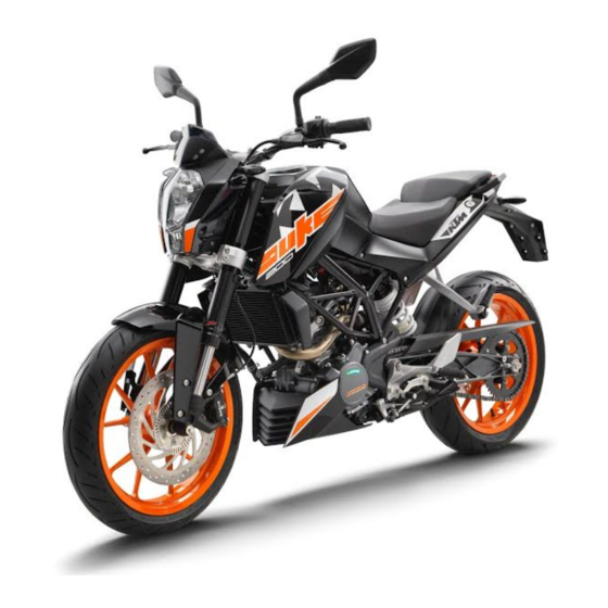
200 Duke
Art. no. 3213562en
Related Manuals for KTM 200 Duke 2017
Summary of Contents for KTM 200 Duke 2017
-
Page 1
OWNER’S MANUAL 2017 200 Duke Art. no. 3213562en… -
Page 3
KTM accepts no liability for delivery options, devi- ations from illustrations and descriptions, misprints, and other errors. -
Page 4
Reproduction, even in part, as well as copying of all kinds, is permitted only with the express written permission of the copyright owner. ISO 9001(12 100 6061) According to the international quality management standard ISO 9001, KTM uses quality assurance processes that lead to the maximum possible quality of the products. -
Page 5: Table Of Contents
TABLE OF CONTENTS CONTROLS…………..22 TABLE OF CONTENTS MEANS OF REPRESENTATION ……..7 Clutch lever…………22 Symbols used …………7 Hand brake lever……….22 Formats used…………8 Throttle grip …………23 SAFETY ADVICE………….. 9 Horn button…………23 Use definition…………9 Light switch …………
-
Page 6
TABLE OF CONTENTS 6.13.14 Average fuel consumption 2/service menu ..42 Applying the brakes……….65 6.13.15 Service/range menu……..43 Stopping, parking……….67 6.13.16 Range/riding time menu ……… 44 Transport …………68 6.13.17 Total distance menu ODO ……. 45 Refueling …………69 6.13.18 Distance menu 1 TRIP 1 …….. -
Page 7
TABLE OF CONTENTS 11.15 Fitting front spoiler ……….93 14.8 Adjusting the headlight range……129 12 BRAKE SYSTEM …………94 15 COOLING SYSTEM …………132 12.1 Checking the brake discs ……..94 15.1 Cooling system ……….132 12.2 Checking the brake fluid level of the front brake … 95 15.2 Checking the antifreeze and coolant level … -
Page 8
TABLE OF CONTENTS 21.3 Capacities …………162 21.3.1 Engine oil ……….. 162 21.3.2 Coolant …………163 21.3.3 Fuel …………163 21.4 Chassis …………163 21.5 Electrical system……….164 21.6 Tires …………… 165 21.7 Fork…………..165 21.8 Shock absorber ……….166 21.9 Chassis tightening torques …….. -
Page 9: Means Of Representation
All work marked with this symbol requires specialist knowledge and technical understanding. In the interest of your own safety, have these jobs performed by an authorized KTM workshop. There, your motorcycle will be optimally cared for by specially trained experts using the specialist tools required.
-
Page 10: Formats Used
MEANS OF REPRESENTATION Formats used The typographical formats used in this document are explained below. Specific name Identifies a proprietary name. Name ® Identifies a protected name. Brand™ Identifies a brand available on the open market. Underlined terms Refer to technical details of the vehicle or indicate technical terms that are explained in the glossary.
-
Page 11: Safety Advice
SAFETY ADVICE Use definition KTM sport motorcycles are designed and constructed to meet the normal demands of regular road operation but not for use on race courses or offroad. Info The motorcycle is authorized for public road traffic in the homologous version only.
-
Page 12: Degrees Of Risk And Symbols
SAFETY ADVICE Degrees of risk and symbols Danger Indicates a danger that will immediately and invariably lead to fatal or serious permanent injury if the appropriate measures are not taken. Warning Indicates a danger that is likely to lead to fatal or serious injury if the appropriate measures are not taken. Caution Indicates a danger that may lead to minor injuries if the appropriate measures are not taken.
-
Page 13: Safe Operation
Only operate the vehicle when it is in perfect technical condition, in accordance with its intended use, and in a safe and environmentally compatible manner. An appropriate driver’s license is needed to ride the vehicle on public roads. Have malfunctions that impair safety promptly eliminated by an authorized KTM workshop. Adhere to the information and warning labels on the vehicle.
-
Page 14: Protective Clothing
– Always wear protective clothing that is in good condition and meets the legal regulations. In the interest of your own safety, KTM recommends that you only operate the vehicle while wearing protective clothing. Work rules Special tools are necessary for certain tasks. The tools are not contained in the vehicle but can be ordered under the number in parenthe- ses.
-
Page 15: Owner’s Manual
Keep the Owner’s Manual in an accessible place to enable you to refer to it as needed. If you would like to know more about the vehicle or have questions on the material you read, please contact an authorized KTM dealer.
-
Page 16: Important Notes
Manufacturer and implied warranty The work specified in the service schedule may only be performed in an authorized KTM workshop and must be recorded in both the Service & Warranty Booklet and in KTM Dealer.net, otherwise any warranty coverage will become void. Damage or secondary damage caused by tampering with and/or conversions on the vehicle are not covered by the warranty.
-
Page 17: Service
Please follow the instructions in the text. Customer service Your authorized KTM dealer will be happy to answer any questions you may have on your vehicle and KTM. A list of authorized KTM dealers can be found on the KTM website.
-
Page 18: View Of Vehicle
VIEW OF VEHICLE View of vehicle, front left (example) S00654-10…
-
Page 19
VIEW OF VEHICLE Combination instrument Rear mirror Clutch lever ( p. 22) Seat Passenger seat Seat lock ( p. 52) Grab handles ( p. 53) Engine number ( p. 21) Side stand ( p. 55) Shift lever ( p. 54) -
Page 20: View Of Vehicle, Rear Right (Example)
VIEW OF VEHICLE View of vehicle, rear right (example) S00655-10…
-
Page 21
VIEW OF VEHICLE Tool set ( p. 52) Light switch ( p. 24) High beam flasher button ( p. 24) Turn signal switch ( p. 25) Horn button ( p. 23) Filler cap Electric starter button ( p. 26) Emergency OFF switch ( p. -
Page 22: Serial Numbers
SERIAL NUMBERS Chassis number The chassis number is stamped on the right side of the steering head. 0 0 1 402408-10 Type label The type label is on the right of the frame behind the steering head. 0 0 1 402174-10…
-
Page 23: Engine Number
SERIAL NUMBERS Engine number The engine number is stamped on the left side of the engine under the engine sprocket. 402486-10 Key number The key number can be found on the KEYCODECARD. Info You need the key number to order a spare key. Keep the KEYCODECARD in a safe place.
-
Page 24: Controls
CONTROLS Clutch lever The clutch lever is fitted on the left side of the handlebar. S00656-10 Hand brake lever The hand brake lever is fitted on the right side of the handlebar. The front brake is engaged using the hand brake lever. S00663-10…
-
Page 25: Throttle Grip
CONTROLS Throttle grip The throttle grip is fitted on the right side of the handlebar. S00664-10 Horn button The horn button is fitted on the left side of the handlebar. Possible states • Horn button in neutral position pressed – The horn is operated in this position. •…
-
Page 26: Light Switch
CONTROLS Light switch The light switch is fitted on the left side of the handlebar. Possible states Low beam on – The light switch is turned downward. In this position, the low beam and the tail light are switched on. High beam on –…
-
Page 27: Turn Signal Switch
CONTROLS Turn signal switch The turn signal switch is fitted on the left side of the handlebar. Possible states Turn signal off Turn signal, left, on – Turn signal switch pressed to the left. The turn signal switch returns automatically to the central position after use. Turn signal, right, on –…
-
Page 28: Electric Starter Button
CONTROLS Electric starter button The electric starter button is fitted on the right side of the handlebar. Possible states • Electric starter button in basic position pressed – In this position, the electric starter is actuated. • Electric starter button S00662-10 6.10 Ignition/steering lock…
-
Page 29: Locking The Steering
CONTROLS 6.11 Locking the steering Note Danger of damage The parked vehicle can roll away or fall over. – Park the vehicle on a firm and level surface. – Park the vehicle. – Turn the handlebar all the way to the left. –…
-
Page 30: Combination Instrument
CONTROLS 6.13 Combination instrument 6.13.1 Overview Display ( p. 35) Function buttons ( p. 33) Info display ( p. 39) Indicator lamps ( p. 34) 401685-10…
-
Page 31: Activation And Test
CONTROLS 6.13.2 Activation and test Activation The combination instrument is activated when the ignition is switched on. Test The segments of the tachometer and the gear display light up and switch off in sequence. The speed display counts from 0 to 199 and back. The remaining display segments outside the info display light up briefly.
-
Page 32: Warning Notes
CONTROLS 6.13.3 Warning notes Low Oil Pressure appears on the info display if the oil pressure is too low. 401309-01 Low Fuel Level appears on the info display if the fuel level reaches the reserve mark. 401310-01…
-
Page 33
CONTROLS High Coolant Temperature appears on the info display if the coolant temperature rises above the specified value. Coolant temperature 110 °C (230 °F) 401311-01 Side Stand Down appears on the info display if the side stand is folded down. 401312-01 Low Battery appears on the info display if the battery voltage falls below the specified value. -
Page 34
CONTROLS Service Not Reset appears on the info display for 10 seconds when the ignition is switched on and the distance interval between service appointments has been exceeded or the service interval display was not reset during a service appointment. 401461-01… -
Page 35: Function Buttons
CONTROLS 6.13.4 Function buttons You can change the display mode with the MODE button Possible display modes are total distance traveled (TRIP 1), distance 1 (ODO) and distance 2 (TRIP 2). Pressing and holding the SET button resets the distance 1 (TRIP 1) and distance 2 (TRIP 2) functions to 0.0 and briefly pressing the SET button changes the info display to the next display mode.
-
Page 36: Indicator Lamps
CONTROLS 6.13.5 Indicator lamps Possible states The turn signal indicator lamp flashes green simultaneously with the turn signal – The turn signal is switched on. Engine diagnosis warning lamp (MIL) lights up yellow – The OBD (on-board diagnosis) has detected an emission- or safety-critical error. The shift warning lights up/flashes red –…
-
Page 37: Display
CONTROLS 6.13.6 Display The speed is shown in kilometers per hour km/h or in miles per hour mph. The tachometer shows the engine speed in revolutions per minute. The gear display shows the engaged gear. The coolant temperature appears in segment The time appears in segment The filling level in the fuel tank is displaced in segment The info display…
-
Page 38: Filling Level Display Of The Fuel Tank
CONTROLS 6.13.7 Filling level display of the fuel tank The filling level display consists of 9 bars. The more bars are lit, the more fuel is in the fuel tank. 401292-01…
-
Page 39: Trip F Display
CONTROLS 6.13.8 TRIP F display If the fuel level drops to the reserve mark, the display mode automatically changes to TRIP F and starts to count from 0.0, regardless of the previous display mode. Info At the same time as the display mode TRIP F, the general warning lamp lights up and the warning note Low Fuel Level appears on the info display.
-
Page 40: Coolant Temperature Indicator
CONTROLS 6.13.9 Coolant temperature indicator The temperature display consists of 13 bars. The more bars that light up, the hotter the coolant. When all bars light up, the following warning note appears on the info display: High Coolant Temperature. Possible states Engine cold –…
-
Page 41: Info Display
CONTROLS 6.13.10 Info display Various warning notes appear on info display If the general warning lamp lights up, the corresponding warning note is shown on the info display. 401291-10…
-
Page 42: 6.13.11 Riding Time/Average Speed Menu
CONTROLS 6.13.11 Riding time/average speed menu Condition Alternative 1 • The ignition is on. • The motorcycle is stationary. Alternative 2 • The ignition is on. • The motorcycle is moving. – Press the SET button briefly and repeatedly until the desired info display appears. The riding time and average speed are displayed in this menu.
-
Page 43: 6.13.13 Average Fuel Consumption 1/Average Fuel Consumption 2 Menu
CONTROLS Info The average fuel consumption 1 is displayed after several 100 meters of travel after the ignition is switched on. If the ignition was switched off for over 60 minutes, the display of the average speed and average fuel consumption 1 is reset to 0. Press the SET button Next display mode on the info display briefly.
-
Page 44: 6.13.14 Average Fuel Consumption 2/Service Menu
CONTROLS 6.13.14 Average fuel consumption 2/service menu Condition Alternative 1 • The ignition is on. • The motorcycle is stationary. Alternative 2 • The ignition is on. • The motorcycle is moving. – Press the SET button briefly and repeatedly until the desired info display appears. The average fuel consumption 2 in km/L (or miles/L) and the distance to the next service 401467-01 are displayed in this menu.
-
Page 45: 6.13.15 Service/Range Menu
CONTROLS 6.13.15 Service/range menu Condition Alternative 1 • The ignition is on. • The motorcycle is stationary. Alternative 2 • The ignition is on. • The motorcycle is moving. – Press the SET button briefly and repeatedly until the desired info display appears. This menu shows the distance to the next service and the range.
-
Page 46: 6.13.16 Range/Riding Time Menu
CONTROLS 6.13.16 Range/riding time menu Condition Alternative 1 • The ignition is on. • The motorcycle is stationary. Alternative 2 • The ignition is on. • The motorcycle is moving. – Press the SET button briefly and repeatedly until the desired info display appears. The range and the riding time are displayed in this menu.
-
Page 47: 6.13.17 Total Distance Menu Odo
CONTROLS 6.13.17 Total distance menu ODO Condition Alternative 1 • The ignition is on. • The motorcycle is stationary. Alternative 2 • The ignition is on. • The motorcycle is moving. – Press the MODE button briefly and repeatedly until ODO appears on the display. ODO shows the total distance covered.
-
Page 48: Distance Menu 1 Trip 1
CONTROLS 6.13.18 Distance menu 1 TRIP 1 Condition Alternative 1 • The ignition is on. • The motorcycle is stationary. Alternative 2 • The ignition is on. • The motorcycle is moving. – Press the MODE button briefly and repeatedly until TRIP 1 appears on the display. TRIP 1shows the distance since the last reset, such as between two refueling stops.
-
Page 49: 6.13.20 Setting Kilometers Or Miles
CONTROLS Press the SET button Display of TRIP 2 is reset for 5 — 10 seconds. Press the MODE but- Next display mode on the display ton. 6.13.20 Setting kilometers or miles Info Make the country-specific setting. Condition The ignition is on. The motorcycle is stationary.
-
Page 50: Adjusting The Shift Speed Rpm 1
CONTROLS – Press the MODE button briefly and repeatedly until ODO appears on the display. – Press the MODE and SET buttons for 5 — 10 seconds. The time display begins to flash. – Set the hours display using the MODE button. –…
-
Page 51: Adjusting The Shift Speed Rpm 2
CONTROLS The display RPM 1 goes out and the set speed is stored. 6.13.23 Adjusting the shift speed RPM 2 Condition The ignition is on. The motorcycle is stationary. – Press the MODE button briefly and repeatedly until TRIP 2 appears on the display. –…
-
Page 52: Opening The Filler Cap
CONTROLS 6.14 Opening the filler cap Danger Fire hazard Fuel is highly flammable. The fuel in the fuel tank expands when warm and can escape if overfilled. – Do not refuel the vehicle in the vicinity of open flames or lit cigarettes. –…
-
Page 53: Closing The Filler Cap
CONTROLS – Lift the cover of the filler cap and insert the ignition key in the lock. Note Danger of damage The ignition key may break if overloaded. Damaged ignition keys must be replaced. – Push down on the filler cap to take pressure off the ignition key. –…
-
Page 54: Seat Lock
CONTROLS 6.16 Seat lock The seat lock is located to the left of the seat. The seat lock can be unlocked using the ignition key. B00712-01 6.17 Tool set The tool set is located under the passenger seat. B00758-10…
-
Page 55: Grab Handles
CONTROLS 6.18 Grab handles The grab handles are used for moving the motorcycle around. If you carry a passenger, the passenger can hold onto the grab handles during the trip. B00717-10 6.19 Passenger footrests The passenger footrests can be folded in and out. Possible states Passenger footrests folded up –…
-
Page 56: Shift Lever
CONTROLS 6.20 Shift lever Shift lever is mounted on the left side of the engine. 401950-10 The gear positions can be seen in the photograph. The neutral or idle position is between the first and second gears. 401950-11…
-
Page 57: Foot Brake Lever
CONTROLS 6.21 Foot brake lever Foot brake lever is located in front of the right footrest. The foot brake lever is used to activate the rear brake. 402177-10 6.22 Side stand The side stand is on the left side of the vehicle. The side stand is used to park the motorcycle.
-
Page 58: Preparing For Use
Warning Danger of accidents Non-approved or non-recommended tires and wheels impact the handling characteristic. – Only use tires/wheels approved by KTM with the corresponding speed index. Warning Danger of accidents New tires have reduced road grip. The contact surface on new tires is not yet roughened.
-
Page 59: Running In The Engine
When using your vehicle, remember that others may feel disturbed by excessive noise. – Make sure that the pre-delivery inspection work has been carried out by an authorized KTM workshop. You receive a delivery certificate and the Service and Warranty Booklet at vehicle handover.
-
Page 60: Loading The Vehicle
PREPARING FOR USE Loading the vehicle Warning Danger of accidents Total weight and axle loads influence the handling characteristic. The overall weight consists of: motorcycle ready for operation and with a full tank, driver and passenger with protective clothing and helmet, and luggage. –…
-
Page 61
PREPARING FOR USE – If you carry any baggage, make sure it is fixed firmly as close as possible to the center of the vehicle and ensure even weight distribu- tion between the front and rear wheels. – Do not exceed the overall maximum permitted weight and the axle loads. Guideline Maximum permissible overall weight 335 kg (739 lb.) -
Page 62: Riding Instructions
RIDING INSTRUCTIONS Checks and maintenance when preparing for use Info Before every trip, check the condition of the vehicle and ensure that it is roadworthy. The vehicle must be in perfect technical condition when used. – Check the engine oil level. ( p.
-
Page 63: Starting
RIDING INSTRUCTIONS Starting Danger Danger of poisoning Exhaust gases are toxic and inhaling them may result in unconsciousness and death. – Always make sure there is sufficient ventilation when running the engine. – Use an effective exhaust extraction system when starting or running the engine in an enclosed space. Caution Danger of accidents Electronic components and safety devices will be damaged if the battery is discharged or missing.
-
Page 64: Starting Off
RIDING INSTRUCTIONS – Unlock the steering. ( p. 27) – Sit on the vehicle, take the weight off of the side stand, and move up all the way. – Turn the emergency OFF switch to the position – Switch on the ignition by turning the ignition key to the position After you switch on the ignition, you can hear the fuel pump working for about two seconds.
-
Page 65: Shifting, Riding
RIDING INSTRUCTIONS If the engine dies while starting off, only pull the clutch lever and press the electric starter button. You do not need to shift into neutral. Shifting, riding Warning Danger of accidents Abrupt load alterations can cause the vehicle to get out of control. –…
-
Page 66
RIDING INSTRUCTIONS Warning Danger of accidents A risky riding style constitutes a major risk. – Comply with traffic regulations and ride defensively and with foresight to detect sources of danger as early as possible. Warning Danger of accidents Cold tires have reduced road grip. –… -
Page 67: Applying The Brakes
RIDING INSTRUCTIONS Info If you hear unusual noises while riding, stop immediately, switch off the engine and contact an authorized KTM workshop. – When conditions allow (incline, road situation, etc.), you can shift into a higher gear. – Release the throttle while simultaneously pulling the clutch lever, shift into the next gear, release the clutch and open the throttle.
-
Page 68
Danger of accidents A spongy pressure point on the front or rear brake reduces braking efficiency. – Check the brake system and do not continue riding until the problem is eliminated. (Your authorized KTM workshop will be glad to help.) Warning Danger of accidents The brake system fails in the event of overheating. -
Page 69: Stopping, Parking
RIDING INSTRUCTIONS Stopping, parking Warning Risk of injury People who act without authorization endanger themselves and others. – Do not leave the vehicle unattended if the engine is running. – Protect the vehicle against access by unauthorized persons. – Lock the steering and remove the ignition key if you leave the vehicle unattended. Warning Danger of burns Some vehicle components become very hot when the vehicle is operated.
-
Page 70: Transport
RIDING INSTRUCTIONS – Shift gear to neutral. – Switch off the ignition by turning the ignition key to the position Info If the engine is switched off with the emergency OFF switch and the ignition remains switched on at the ignition lock, power continues to flow to most power consumers and the battery will discharge.
-
Page 71: Refueling
RIDING INSTRUCTIONS – Switch off the engine and remove the ignition key. – Use tension belts or other suitable devices to secure the motorcycle against accidents or falling over. 401448-01 Refueling Danger Fire hazard Fuel is highly flammable. The fuel in the fuel tank expands when warm and can escape if overfilled. –…
-
Page 72
In some countries and regions, the available fuel quality and cleanliness may not be sufficient. This will result in problems with the fuel system. – Refuel only with clean fuel that meets the specified standards. (Your authorized KTM workshop will be glad to help.) Warning Environmental hazard Improper handling of fuel is a danger to the environment. -
Page 73
RIDING INSTRUCTIONS – Switch off the engine. – Open the filler cap. ( p. 50) – Fill the fuel tank with fuel up to the lower edge of the fuel filler. Total fuel tank 11 l (2.9 US gal) Super unleaded (ROZ 95/RON capacity, approx. -
Page 74: Service Schedule
15,000 km (9,300 mi) every 7,500 km (4,650 mi) after 1,000 km (620 mi) ○ ● ● ● ● Read out the fault memory using the KTM diagnostics tool. ○ ● ● ● ● Check that the electrical system is functioning properly. ○…
-
Page 75
Read out the error memory after the test ride using the KTM diagnostics tool. ○ ● ● Reset the service interval display. ○ ● ● ● ● Make the service entry in the KTM Dealer.net and in the Service and Warranty Booklet. ○ One-time interval ● Periodic interval… -
Page 76: Recommended Work
SERVICE SCHEDULE Recommended work Every four years Every year every 30,000 km (18,600 mi) every 7,500 km (4,650 mi) after 1,000 km (620 mi) ● Check the frame. ● Check the swingarm. ● ● Check the swingarm bearing. ● ● Check the wheel bearing for play.
-
Page 77: Tuning The Chassis
TUNING THE CHASSIS 10.1 Adjusting the spring preload of the shock absorber Warning Danger of accidents Modifications to the suspension settings can seriously alter the vehicle’s ride behavior. – Following modifications, ride slowly at first to get the feel of the new ride behavior. Info The spring preload defines the initial situation of the spring process on the shock absorber.
-
Page 78: Adjusting The Shift Lever
TUNING THE CHASSIS 10.2 Adjusting the shift lever Info The adjustment range of the shift lever is limited. – Loosen nuts – Adjust the shift lever by turning shift rod Guideline 110… 122 mm (4.33… 4.8 in) Shift rod adjustment range Info Make the same adjustments on both sides.
-
Page 79: Service Work On The Chassis
SERVICE WORK ON THE CHASSIS 11.1 Raising the motorcycle with the rear lifting gear Note Danger of damage The parked vehicle can roll away or fall over. – Park the vehicle on a firm and level surface. – Mount the supports of the lifting gear. –…
-
Page 80: Lifting The Motorcycle With The Front Lifting Gear
SERVICE WORK ON THE CHASSIS – Secure the motorcycle against falling over. – Remove the rear lifting gear and lean the vehicle on side stand – Remove bushings kit. 402029-10 11.3 Lifting the motorcycle with the front lifting gear Note Danger of damage The parked vehicle can roll away or fall over.
-
Page 81: Taking The Motorcycle Off Of The Front Wheel Stand
SERVICE WORK ON THE CHASSIS – Move the handlebar to the straight-ahead position. Position the lifting gear. Mounting pin (69329965030) Lifting gear, front (69329965000) Info Always raise the motorcycle at the rear first. – Raise the motorcycle at the front. C00197-01 11.4 Taking the motorcycle off of the front wheel stand…
-
Page 82: Removing The Passenger Seat
SERVICE WORK ON THE CHASSIS – Mount protection cap M00005-10 Finishing work – Remove the rear of the motorcycle from the lifting gear. ( p. 77) 11.5 Removing the passenger seat – Insert the ignition key in seat lock and turn it clockwise. –…
-
Page 83: Mounting The Passenger Seat
SERVICE WORK ON THE CHASSIS 11.6 Mounting the passenger seat – Attach hooks on the passenger seat to brackets on the subframe, and lower it at the rear while pushing forward. – Press down the passenger seat until it clicks into place. Warning Danger of accidents The passenger seat can come loose from the anchoring if it is not mounted correctly.
-
Page 84: Mounting The Seat
SERVICE WORK ON THE CHASSIS 11.8 Mounting the seat Main work – Attach seat recesses at screws and lower at the rear. – Mount and tighten screws Guideline Screw, seat 10 Nm (7.4 lbf ft) B00727-10 Finishing work – Mount the passenger seat. ( p.
-
Page 85: Checking For Chain Dirt Accumulation
SERVICE WORK ON THE CHASSIS 11.9 Checking for chain dirt accumulation – Check the chain for coarse dirt accumulation. » If the chain is very dirty: – Clean the chain. ( p. 83) 400678-01 11.10 Cleaning the chain Warning Danger of accidents Oil or grease on the tires reduces the road grip. –…
-
Page 86: Checking The Chain Tension
SERVICE WORK ON THE CHASSIS Info The service life of the chain depends largely on its maintenance. Preparatory work – Raise the motorcycle with the rear lifting gear. ( p. 77) Main work – Clean the chain regularly. – Rinse off loose dirt with a soft jet of water. –…
-
Page 87
SERVICE WORK ON THE CHASSIS Preparatory work – Raise the motorcycle with the rear lifting gear. ( p. 77) Main work – Shift gear to neutral. – In the area of the chain sliding guard, press the chain upward toward the swingarm and determine chain tension Info Upper chain section… -
Page 88: Adjusting The Chain Tension
SERVICE WORK ON THE CHASSIS 11.12 Adjusting the chain tension Warning Danger of accidents Incorrect chain tension damages components and results in accidents. If the chain is tensioned too much, the chain, engine sprocket, rear sprocket, transmission and rear wheel bearings wear more quickly.
-
Page 89
SERVICE WORK ON THE CHASSIS Main work – Loosen nut – Loosen nuts – Adjust the chain tension by turning adjusting screws left and right. Guideline Chain tension 5… 7 mm (0.2… 0.28 in) Turn the adjusting screws on the left and right so that the markings on the left and right chain adjusters are in the same position relative to the reference marks… -
Page 90: Checking The Chain, Rear Sprocket, And Engine Sprocket
SERVICE WORK ON THE CHASSIS 11.13 Checking the chain, rear sprocket, and engine sprocket Preparatory work – Raise the motorcycle with the rear lifting gear. ( p. 77) Main work – Check the rear sprocket and engine sprocket for wear. »…
-
Page 91
SERVICE WORK ON THE CHASSIS – Shift gear to neutral. – Pull the lower chain section with specified weight Guideline Weight, chain wear measurement 15 kg (33 lb.) – Measure distance of 20 chain rollers in the lower chain section. Info 0 0 A Chain wear is not always even, so you should repeat this measurement at differ-… -
Page 92
SERVICE WORK ON THE CHASSIS – Remove screws . Push the chain guard aside. S00670-10 – Check the chain sliding guard for wear. » If the chain sliding guard has lost material due to wear to the extent that, in area , drilled hole is visible from above:… -
Page 93
SERVICE WORK ON THE CHASSIS – Position the chain guard and tighten screw Guideline Screw, chain guard EJOT PT ® 4 Nm (3 lbf ft) – Tighten screw Guideline Screw, chain guard EJOT PT ® 4 Nm (3 lbf ft) –… -
Page 94: Removing The Front Spoiler
SERVICE WORK ON THE CHASSIS 11.14 Removing the front spoiler – Remove screws B00770-10 – Remove screws – Take off the front spoiler. B00771-10…
-
Page 95: Fitting Front Spoiler
SERVICE WORK ON THE CHASSIS 11.15 Fitting front spoiler – Position the front spoiler. Mount screws but do not tighten yet. B00770-10 – Mount and tighten screws Guideline Screw, front spoiler 9 Nm (6.6 lbf ft) – Tighten screw Guideline Screw, front spoiler 9 Nm (6.6 lbf ft) B00771-10…
-
Page 96: Brake System
Danger of accidents Worn-out brake discs reduce the braking effect. – Make sure that worn-out brake discs are replaced immediately. (Your authorized KTM workshop will be glad to help.) – Check the thickness of the front and rear brake discs at multiple points on each brake…
-
Page 97: Checking The Brake Fluid Level Of The Front Brake
If the brake fluid level drops below the MIN marking, the brake system is leaking or the brake linings are worn down. – Check the brake system and do not continue riding until the problem is eliminated. (Your authorized KTM workshop will be glad to help.) Warning Danger of accidents Old brake fluid reduces the braking effect.
-
Page 98: Adding Front Brake Fluid
If the brake fluid level drops below the MIN marking, the brake system is leaking or the brake linings are worn down. – Check the brake system and do not continue riding until the problem is eliminated. (Your authorized KTM workshop will be glad to help.) Warning Skin irritation Brake fluid causes skin irritation.
-
Page 99: Adding Front Brake Fluid
Clean up overflowed or spilt brake fluid immediately with water. 12.4 Checking the front brake linings Warning Danger of accidents Worn-out brake linings reduce the braking effect. – Ensure that worn-out brake linings are replaced immediately. (Your authorized KTM workshop will be glad to help.)
-
Page 100: Checking The Free Travel Of Foot Brake Lever
BRAKE SYSTEM Warning Danger of accidents Damaged brake discs reduce the braking effect. If the brake linings are not changed in time, the brake lining carriers grind against the brake disc. As a consequence, the braking effect is greatly reduced and the brake discs are destroyed. –…
-
Page 101: Adjusting The Free Travel Of The Foot Brake Lever
BRAKE SYSTEM – Disconnect spring – Move the foot brake lever back and forth between the end stop and the contact to the foot brake cylinder piston and check free travel Guideline Free travel at foot brake lever 3… 5 mm (0.12… 0.2 in) »…
-
Page 102: Checking The Rear Brake Fluid Level
If the brake fluid level drops below the MIN marking, the brake system is leaking or the brake linings are worn down. – Check the brake system and do not continue riding until the problem is eliminated. (Your authorized KTM workshop will be glad to help.)
-
Page 103: Adding Rear Brake Fluid
If the brake fluid level drops below the MIN marking, the brake system is leaking or the brake linings are worn down. – Check the brake system and do not continue riding until the problem is eliminated. (Your authorized KTM workshop will be glad to help.)
-
Page 104
Danger of accidents Old brake fluid reduces the braking effect. – Make sure that brake fluid for the front and rear brake is changed in accordance with the service schedule. (Your authorized KTM workshop will be glad to help.) Warning Environmental hazard Hazardous substances cause environmental damage. -
Page 105
BRAKE SYSTEM Main work Condition The screw cap is locked. – Remove screw and take off the screw cap lock. H01142-10 – Stand the vehicle upright. – Remove screw cap with membrane – Add brake fluid to level Brake fluid DOT 4 / DOT 5.1 ( p. -
Page 106: Adding Rear Brake Fluid
Warning Danger of accidents Worn-out brake linings reduce the braking effect. – Ensure that worn-out brake linings are replaced immediately. (Your authorized KTM workshop will be glad to help.) Warning Danger of accidents Damaged brake discs reduce the braking effect. If the brake linings are not changed in time, the brake lining carriers grind against the brake disc. As a consequence, the braking effect is greatly reduced and the brake discs are destroyed.
-
Page 107: Wheels, Tires
WHEELS, TIRES 13.1 Removing the front wheel Preparatory work – Raise the motorcycle with the rear lifting gear. ( p. 77) – Lift the motorcycle with the front lifting gear. ( p. 78) Main work – Loosen screw by several rotations. –…
-
Page 108
WHEELS, TIRES Main work – Check the wheel bearing for damage and wear. » If the wheel bearing is damaged or worn: – Change the wheel bearing. – Clean and grease the shaft seal rings and mating surfaces of the spacers. Long-life grease ( p. -
Page 109: Removing The Rear Wheel
WHEELS, TIRES 13.3 Removing the rear wheel Preparatory work – Raise the motorcycle with the rear lifting gear. ( p. 77) Main work – Remove nut and washer. – Remove chain adjuster – Hold rear wheel and wheel spindle pull out with washer and chain adjuster –…
-
Page 110: Installing The Rear Wheel
WHEELS, TIRES 13.4 Installing the rear wheel Warning Danger of accidents Oil or grease on the brake discs reduces the braking effect. – Always keep the brake discs free of oil and grease. – Clean the brake discs with brake cleaner when necessary. Warning Danger of accidents There is no braking effect to start with at the rear brake after installing the rear wheel.
-
Page 111: Checking The Rear Hub Rubber Dampers
WHEELS, TIRES – Pull the rear wheel back and mount wheel spindle with the washer and chain adjuster Guideline Mount the left and right chain adjusters in the same position. – Mount nut and washer. – Push the rear wheel forward so that the chain adjusters are on the screws, and tighten Guideline In order for the rear wheel to be correctly aligned, the markings on the left and right chain adjusters must be in the same position relative to the reference marks…
-
Page 112
WHEELS, TIRES Preparatory work – Raise the motorcycle with the rear lifting gear. ( p. 77) – Remove the rear wheel. p. 107) Main work – Check bearing » If the bearing is damaged or worn: – Change the bearing. –… -
Page 113: Installing The Rear Wheel
Danger of accidents If a tire bursts while riding, the vehicle becomes uncontrollable. – Ensure that damaged or worn tires are replaced immediately. (Your authorized KTM workshop will be glad to help.) Warning Danger of crashing Different tire tread patterns on the front and rear wheel impair the handling characteristic.
-
Page 114: Checking The Tire Air Pressure
DOT number. The first two digits indicate the week of manufacture and the last two digits the year of manufacture. KTM recommends that the tires be changed after 5 years at the latest, regard- less of the actual state of wear.
-
Page 115
WHEELS, TIRES – Remove the dust cap. – Check tire air pressure when the tires are cold. Tire air pressure, solo Front 2.0 bar (29 psi) Rear 2.0 bar (29 psi) Tire air pressure with passenger/full payload Front 2.0 bar (29 psi) 400695-01 Rear 2.2 bar (32 psi) -
Page 116: Electrical System
ELECTRICAL SYSTEM 14.1 Removing the battery Warning Risk of injury Battery acid and battery gases cause serious chemical burns. – Keep batteries out of the reach of children. – Wear suitable protective clothing and safety glasses. – Avoid contact with battery acid and battery gases. –…
-
Page 117: Installing The Battery
ELECTRICAL SYSTEM – Pull back the positive terminal cover – Disconnect positive cable from the battery. – Detach rubber band – Pull the battery up and out of the battery holder. Info Never operate the motorcycle with a discharged battery or without a battery. In both cases, electrical components and safety devices can be damaged.
-
Page 118: Recharging The Battery
ELECTRICAL SYSTEM – Position the negative cable and mount and tighten the screw. – Position the negative terminal cover B00750-11 Finishing work – Mount the seat. ( p. 82) – Mount the passenger seat. ( p. 81) – Set the clock. ( p.
-
Page 119
ELECTRICAL SYSTEM Warning Environmental hazard Batteries contain environmentally-hazardous materials. – Do not dispose of batteries as household waste. – Dispose of batteries at a collection point for used batteries. Info Even when there is no load on the battery, it discharges steadily. The charging level and the method of charging are very important for the service life of the battery. -
Page 120
ELECTRICAL SYSTEM Main work – Connect the battery charger to the battery. Switch on the battery charger. Battery charger (58429074000) You can also use the battery charger to test rest potential and start potential of the bat- tery, and to test the alternator. With this device, you cannot overcharge the battery. Info Never remove lid Charge the battery with a maximum of 10% of the capacity specified on battery… -
Page 121: Changing The Fuses Of Individual Power Consumers
ELECTRICAL SYSTEM 14.4 Changing the fuses of individual power consumers Info The fuse box with the main fuse and the fuses of the individual power consumers is located under the passenger seat. Preparatory work – Switch off all power consumers and switch off the engine. –…
-
Page 122
ELECTRICAL SYSTEM Info A defective fuse is indicated by a burned-out fuse wire Warning Fire hazard Incorrect fuses overload the electrical system. – Only use fuses with the required ampere value. – Do not bypass or repair fuses. – Use spare fuses with the correct rating only. Fuse (75011088010) ( p. -
Page 123: Changing The Headlight Bulb
ELECTRICAL SYSTEM 14.5 Changing the headlight bulb Note Damage to reflector Grease on the reflector reduces the brightness. Grease on the bulb will evaporate due to the heat and be deposited on the reflector. – Clean and degrease the bulbs before mounting. –…
-
Page 124
ELECTRICAL SYSTEM – Remove screws – Lift the headlight mask slightly and swing forward. 601914-10 – Remove protection cap – Unplug connector B00760-10 – Detach retaining clamp – Remove headlight bulb – Position the new headlight bulb in the headlight housing. Guideline Insert the headlight bulb so that the catches latch into the recesses. -
Page 125
ELECTRICAL SYSTEM – Plug in connector – Mount protection cap B00760-10 – Fold the headlight mask up. – Mount and tighten screws Guideline Screw, headlight mask 11 Nm Loctite ® 243™ (8.1 lbf ft) 601914-10 – Mount expanding rivets on both sides. –… -
Page 126: Changing The Parking Light Bulb
ELECTRICAL SYSTEM 14.6 Changing the parking light bulb Note Damage to reflector Grease on the reflector reduces the brightness. Grease on the bulb will evaporate due to the heat and be deposited on the reflector. – Clean and degrease the bulbs before mounting. –…
-
Page 127
ELECTRICAL SYSTEM – Remove screws – Lift the headlight mask slightly and swing forward. 307324-10 – Remove screws – Remove cover B00762-10… -
Page 128
ELECTRICAL SYSTEM – Pull the socket with bulb out of the housing. – Remove the bulb. – Position a new light bulb in the socket. Parking light (W5W/socket W2.1×9.5d) ( p. 165) – Position the socket with bulb in the housing. B00763-10 –… -
Page 129
ELECTRICAL SYSTEM – Fold the headlight mask up. – Mount and tighten screws Guideline Screw, headlight mask 11 Nm Loctite ® 243™ (8.1 lbf ft) 307324-10 – Mount expanding rivets on both sides. – Check that the lighting is functioning properly. 601915-10… -
Page 130: Checking The Headlight Setting
ELECTRICAL SYSTEM 14.7 Checking the headlight setting – Position the vehicle upright on a horizontal surface in front of a light wall and make a 0 0 A mark at the height of the center of the low beam headlight. –…
-
Page 131: Adjusting The Headlight Range
ELECTRICAL SYSTEM 14.8 Adjusting the headlight range Main work – Remove expanding rivets 601915-10 – Remove screws – Lift the headlight mask slightly and swing forward. 601914-10…
-
Page 132
ELECTRICAL SYSTEM – Adjust the beam distance of the headlight by turning screw Guideline For a motorcycle with rider, and with luggage and a passenger if applicable, the light/dark boundary must be exactly on the lower mark (applied in: Checking headlight adjustment). -
Page 133
ELECTRICAL SYSTEM Finishing work – Check the headlight setting. ( p. 128) -
Page 134: Cooling System
COOLING SYSTEM 15.1 Cooling system Water pump in the engine ensures forced circulation of the coolant. The pressure resulting from the warming of the cooling system is regulated by a valve in the radiator cap . Heat expansion causes excess coolant to flow into compensating tank When the temperature falls, this surplus coolant is sucked back into the cooling system.
-
Page 135
COOLING SYSTEM The coolant is cooled by the air stream and a radiator fan , which is controlled by a ther- moswitch. The lower the speed, the less the cooling effect. Dirty cooling fins also reduce the cooling effect. 401768-10… -
Page 136: Checking The Antifreeze And Coolant Level
COOLING SYSTEM 15.2 Checking the antifreeze and coolant level Warning Danger of scalding During motorcycle operation, the coolant gets very hot and is under pressure. – Do not open the radiator, the radiator hoses or other cooling system components if the engine or the cooling system are at oper- ating temperature.
-
Page 137
COOLING SYSTEM – Stand the motorcycle upright on a horizontal surface. – Remove the cap of the compensating tank – Check the coolant antifreeze. −25… −45 °C (−13… −49 °F) » If the antifreeze in the coolant does not match the specified value: –… -
Page 138: Checking The Coolant Level
COOLING SYSTEM » If you had to add more coolant than the specified amount: > 0.20 l (> 0.21 qt.) – Fill/bleed the cooling system. p. 139) – Mount the radiator cap. 15.3 Checking the coolant level Warning Danger of scalding During motorcycle operation, the coolant gets very hot and is under pressure. –…
-
Page 139
COOLING SYSTEM – Stand the motorcycle upright on a horizontal surface. – Check the coolant level in the compensating tank The coolant level must be between MIN and MAX. » If the coolant level does not match the specified value: –… -
Page 140: Draining The Coolant
COOLING SYSTEM 15.4 Draining the coolant Warning Danger of scalding During motorcycle operation, the coolant gets very hot and is under pressure. – Do not open the radiator, the radiator hoses or other cooling system components if the engine or the cooling system are at oper- ating temperature.
-
Page 141: Filling/Bleeding The Cooling System
COOLING SYSTEM Main work – Position the motorcycle upright. – Place a suitable container under the engine. – Remove screw – Remove the radiator cap. – Completely drain the coolant. – Mount and tighten screw with a new seal ring. Guideline B00768-10 Screw plug, water pump drain hole…
-
Page 142
COOLING SYSTEM Main work – Remove radiator cap B01552-11 – Loosen bleeder screw Guideline 3 turns – Tilt the vehicle slightly to the right. – Pour in coolant until it emerges without bubbles at the bleeder screw, and then mount and tighten the bleeder screw immediately. -
Page 143
COOLING SYSTEM – Start the engine and let it warm up. – Stop the engine and allow it to cool down. – When the engine is cool, check the coolant level in the radiator and, if necessary, add coolant. – Remove the cover of compensating tank and top up the coolant level up to the MAXmarking. -
Page 144: Tuning The Engine
TUNING THE ENGINE 16.1 Checking the play in the throttle cable – Check the throttle grip for smooth operation. – Move the handlebar to the straight-ahead position. Turn the throttle grip back and forth slightly and determine the play in throttle cable 3……
-
Page 145: Adjusting The Play In The Throttle Cable
TUNING THE ENGINE 16.2 Adjusting the play in the throttle cable – Move the handlebar to the straight-ahead position. – Push back sleeve – Loosen lock nut – Adjust the play in the throttle cable by turning adjusting screw Guideline Throttle cable play 3……
-
Page 146: Adjusting Play In The Clutch Lever
TUNING THE ENGINE The clutch lever play must not change. » If the clutch lever play changes: – Check the routing of the clutch cable. 16.4 Adjusting play in the clutch lever – Move the handlebar to the straight-ahead position. –…
-
Page 147: Service Work On The Engine
SERVICE WORK ON THE ENGINE 17.1 Checking the engine oil level Condition The engine is at operating temperature. Preparatory work – Stand the motorcycle upright on a horizontal surface. Main work – Check the engine oil level. Info After switching off the engine, wait one minute before checking the level. The engine oil must be between the markings »…
-
Page 148
SERVICE WORK ON THE ENGINE Warning Environmental hazard Hazardous substances cause environmental damage. – Dispose of oils, grease, filters, fuel, cleaning agents, brake fluid, etc., correctly and in compliance with the applicable regula- tions. Info Drain the engine oil only when the engine is warm. Preparatory work –… -
Page 149
SERVICE WORK ON THE ENGINE – Remove screws . Remove oil filter cover with the O-ring. – Pull oil filter out of the oil filter housing. Circlip pliers reverse (51012011000) – Completely drain the engine oil. – Thoroughly clean the parts and sealing surface. B00775-10 –… -
Page 150: Adding Engine Oil
SERVICE WORK ON THE ENGINE – Remove filler plug and the O-ring from the clutch cover, and fill up with engine oil. Engine oil 1.5 l (1.6 qt.) External temper- Engine oil ature: 0… 50 °C (SAE 15W/50) (32… 122 °F) p.
-
Page 151
SERVICE WORK ON THE ENGINE Main work – Remove the oil filler plug with the O-ring from the clutch cover and fill up with engine oil. Engine oil (SAE 15W/50) ( p. 172) Engine oil (SAE 10W/40) ( p. 172) Info For optimal performance of the engine oil, do not mix different types of engine oil. -
Page 152: Cleaning, Care
CLEANING, CARE 18.1 Cleaning the motorcycle Note Material damage Components become damaged or destroyed if a pressure cleaner is used incorrectly. The high pressure forces water into the electrical components, connectors, throttle cables, and bearings, etc. Pressure which is too high causes malfunctions and destroys components. –…
-
Page 153
CLEANING, CARE – Seal the exhaust system to keep water out. – First remove coarse dirt particles with a gentle spray of water. – Spray very dirty areas with a normal motorcycle cleaner and then clean with a paint- brush. Motorcycle cleaner ( p. -
Page 154: Checks And Maintenance Steps For Winter Operation
CLEANING, CARE – Clean the chain. ( p. 83) – Treat bare metal parts (except for brake discs and exhaust system) with anti-corrosion materials. Preserving materials for paints, metal and rubber ( p. 176) – Treat all painted parts with a mild paint polish. Perfect Finish and high gloss polish for paints ( p.
-
Page 155
CLEANING, CARE – Clean the motorcycle. ( p. 150) – Clean the brakes. Info After EVERY trip on salted roads, thoroughly wash the brake calipers and brake linings with cold water and dry carefully. This should be done after the parts are cooled down and while they are installed. -
Page 156: Storage
0… 35 °C (32… 95 °F) direct sunlight – Store the vehicle in a dry location that is not subject to large fluctuations in tempera- ture. Info KTM recommends jacking up the motorcycle. – Raise the motorcycle with the rear lifting gear. ( p. 77)
-
Page 157: Preparing For Use After Storage
STORAGE – Lift the motorcycle with the front lifting gear. ( p. 78) – Cover the motorcycle with a tarp or similar cover that is permeable to air. Info Do not use non-porous materials since they prevent humidity from escaping, thus causing corrosion.
-
Page 158: Troubleshooting
Operating error Go through the steps of starting the engine. p. 61) – Fault in fuel injection system Read out the fault memory using the KTM diag- nostics tool. – Engine has too little power Air filter is very dirty Change the air filter.
-
Page 159
Defect in radiator fan system Check the radiator fan system. – The engine diagnosis warning Fault in fuel injection system Read out the fault memory using the KTM diag- lamp (MIL) lights up red nostics tool. – Engine dies during the trip Lack of fuel Refuel. -
Page 160
TROUBLESHOOTING Faults Possible cause Action – Speedometer in combination instru- Speedometer wiring harness is dam- Check the wiring harness and plug-in connector. ment not functioning aged or plug-in connector is oxidized… -
Page 161: Technical Data
TECHNICAL DATA 21.1 Engine Design 1-cylinder 4-stroke engine, water-cooled Displacement 200 cm³ (12.2 cu in) Stroke 49 mm (1.93 in) Bore 72 mm (2.83 in) Compression ratio 11,5:1 Control DOHC, 4 valves controlled via cam lever, chain drive Valve diameter, intake 28.5 mm (1.122 in) Valve diameter, exhaust 24 mm (0.94 in)
-
Page 162: Engine Tightening Torques
TECHNICAL DATA 4th gear 21:26 5th gear 22:23 6th gear 24:22 Mixture preparation Electronically controlled fuel injection Ignition Contactless controlled fully electronic ignition with digital ignition adjustment Alternator 12 V, 230 W Spark plug BOSCH Super R6 VR 5 NE Spark plug electrode gap 0.8 mm (0.031 in) Spark plug…
-
Page 163
TECHNICAL DATA Nut, water pump impeller 10 Nm (7.4 lbf ft) Loctite ® 243™ – Screw plug, water pump drain hole 10 Nm (7.4 lbf ft) – Screw, alternator cover 12 Nm (8.9 lbf ft) Loctite ® 243™ Screw, bearing retainer 12 Nm (8.9 lbf ft) –… -
Page 164: Capacities
TECHNICAL DATA – Nut, manifold on cylinder head 8 Nm (5.9 lbf ft) Screw, balancer shaft gear 40 Nm (29.5 lbf ft) Loctite ® 243™ Screw, camshaft drive sprocket 32 Nm (23.6 lbf ft) Loctite ® 243™ Loctite ® 243™ Screw, return spring, quick shifter 20 Nm (14.8 lbf ft) –…
-
Page 165: Coolant
TECHNICAL DATA 21.3.2 Coolant Coolant 1 l (1 qt.) Coolant ( p. 171) 21.3.3 Fuel Total fuel tank capacity, approx. 11 l (2.9 US gal) Super unleaded (ROZ 95/RON 95/PON 91) ( p. 173) (200 Duke EU/AR/MY/PH) Gasohol 95 E20 (RON 95) ( p.
-
Page 166: Electrical System
TECHNICAL DATA Brake discs — wear limit Front 3.6 mm (0.142 in) Rear 3.6 mm (0.142 in) Tire air pressure, solo Front 2.0 bar (29 psi) Rear 2.0 bar (29 psi) Tire air pressure with passenger/full payload Front 2.0 bar (29 psi) Rear 2.2 bar (32 psi) Secondary ratio…
-
Page 167: Tires
110/70 R 17 M/C 54S TL 150/60 R 17 M/C 66S TL MRF revz FC MRF revz C The tires specified represent one of the possible series production tires. Additional information is available in the Service section under: http://www.ktm.com 21.7 Fork Fork part number 90601000044…
-
Page 168: Shock Absorber
TECHNICAL DATA 21.8 Shock absorber Shock absorber part number 90604010000 Shock absorber WP Suspension Spring preload Standard 3 clicks Full payload 6 clicks Static sag 15 mm (0.59 in) Riding sag 45… 50 mm (1.77… 1.97 in) Fitted length 300 mm (11.81 in) 21.9 Chassis tightening torques –…
-
Page 169
TECHNICAL DATA – Screw, fuel tank closure flange 5 Nm (3.7 lbf ft) – Screw, fuel tank cover 4 Nm (3 lbf ft) – Screw, fuel tank trim 5 Nm (3.7 lbf ft) – Screw, license plate holder 11 Nm (8.1 lbf ft) Screw, rollover sensor 6 Nm (4.4 lbf ft) Loctite… -
Page 170
TECHNICAL DATA – Screw, front seat fixing 6 Nm (4.4 lbf ft) – Screw, front spoiler 9 Nm (6.6 lbf ft) – Screw, fuel tank 13 Nm (9.6 lbf ft) – Screw, headlight holder 11 Nm (8.1 lbf ft) Screw, headlight mask 11 Nm (8.1 lbf ft) Loctite ®… -
Page 171
TECHNICAL DATA – Screw, engine bearer on frame 26 Nm (19.2 lbf ft) Screw, foot brake lever 16 Nm (11.8 lbf ft) Loctite ® 243™ – Screw, fork stub 15 Nm (11.1 lbf ft) Loctite ® 243™ Screw, front brake disc 30 Nm (22.1 lbf ft) –… -
Page 172
TECHNICAL DATA – Screw, front footrest bracket / engine M10x1.25 47 Nm (34.7 lbf ft) bearer Loctite 243™ Screw, side stand bracket M10x1.25 25 Nm (18.4 lbf ft) ® Loctite ® 243™ Screw, top shock absorber M10x1.25 51 Nm (37.6 lbf ft) –… -
Page 173: Substances
SUBSTANCES Brake fluid DOT 4 / DOT 5.1 Standard/classification – Guideline – Use only brake fluid that complies with the specified standard (see specifications on the container) and that exhibits the corresponding properties. Recommended supplier Castrol – REACT PERFORMANCE DOT 4 Motorex ®…
-
Page 174
SUBSTANCES Observe the coolant manufacturer specifications for antifreeze protection, dilution and miscibility (compatibility) with other coolants. Recommended supplier Motorex ® – COOLANT M3.0 Engine oil (SAE 15W/50) Standard/classification – JASO T903 MA ( p. 177) – SAE ( p. 177) (SAE 15W/50) Guideline –… -
Page 175
SUBSTANCES Recommended supplier Motorex ® – Formula 4T Fork oil (SAE 4) (48601166S1) Standard/classification – SAE ( p. 177) (SAE 4) Guideline – Use only oils that comply with the specified standards (see specifications on the container) and that exhibit the corresponding proper- ties. -
Page 176
SUBSTANCES – Fuel with an ethanol content of up to 10 % (E10 fuel) is safe to use. Info Do not use fuel containing methanol (e. g. M15, M85, M100) or more than 10 % ethanol (e. g. E15, E25, E85, E100). Super unleaded, type C (ROZ 95/RON 95/PON 91) Standard/classification –… -
Page 177: Auxiliary Substances
AUXILIARY SUBSTANCES Chain cleaner Recommended supplier Motorex ® – Chain Clean Chain lube for road use Guideline Recommended supplier Motorex ® – Chainlube Road Fuel additive Recommended supplier Motorex ® – Fuel Stabilizer Long-life grease Recommended supplier Motorex ® – Bike Grease 2000 Motorcycle cleaner Recommended supplier…
-
Page 178
AUXILIARY SUBSTANCES Perfect Finish and high gloss polish for paints Recommended supplier Motorex ® – Moto Polish & Shine Preserving materials for paints, metal and rubber Recommended supplier Motorex ® – Moto Protect Special cleaner for glossy and matte paint finishes, metal and plastic surfaces Recommended supplier Motorex ®… -
Page 179: Standards
STANDARDS JASO T903 MA Different technical development directions required a separate specification for 4-stroke motorcycles – the JASO T903 MA standard. Earlier, engine oils from the automobile industry were used for 4-stroke motorcycles because there was no separate motorcycle specifica- tion.
-
Page 180: List Of Abbreviations
LIST OF ABBREVIATIONS Art. no. Article number circa compare e.g. for example etc. et cetera i.a. inter alia number poss. possibly…
-
Page 181: List Of Symbols
LIST OF SYMBOLS 26.1 Red symbols Red symbols indicate an error condition that requires immediate intervention. The immobilizer indicator lamp lights up or flashes red – Status or error message for immobilizer/alarm system (optional). 26.2 Yellow and orange symbols Yellow and orange symbols indicate an error condition that requires prompt intervention. Active driving aids are also represented by yellow or orange symbols.
-
Page 182: Index
INDEX INDEX Capacity Accessories ……..14 coolant .
-
Page 183
INDEX filling level display of the fuel tank ….36 Engine oil level function buttons ……33 checking . -
Page 184
INDEX removing the rear from the lifting gear ….77 taking off of the front wheel stand ….79 Hand brake lever . -
Page 185
INDEX Protective clothing ……. 12 Shifting ……..63 Shock absorber spring preload, adjusting . -
Page 186
INDEX Time adjusting ……..47 Tire air pressure checking . -
Page 187
*3213562en* 3213562en 01/2017 KTM Sportmotorcycle GmbH Photo: Mitterbauer/KTM 5230 Mattighofen/Austria http://www.ktm.com…
Информация, представленная на Сайте, носит информационный характер и ни при каких условиях не является публичной
офертой, определяемой положениями статьи 437 Гражданского кодекса Российской Федерации. Все содержащиеся на
Сайте сведения носят исключительно информационный характер и не являются исчерпывающими. Все условия
приобретения мототехники, цены, спецпредложения и комлектации мототехники указаны с целью ознакомления.
Комплектации и цены действительны на момент публикации и могут быть изменены без предварительного оповещения.
Представленная на Сайте мототехника может быть укомплектована дополнительным оборудованием, не входящим в
стандартную версию, но доступным за дополнительную плату. Сведения о продукции, касающиеся объёмов поставки,
внешнего вида, характеристик, габаритов и веса, эксплуатационных затрат и т.д. не являются обязательными,
рассматриваются как приблизительные и указаны с условием того, что могут возникнуть ошибки при печати, настройке
и/или наборе текста. Такая информация может быть изменена без предварительного уведомления. Чтобы получить
полную информацию о продукции, услугах, дополнительном оборудовании и спецпредложениях, интересных для Вас,
обращайтесь к менеджерам Дилерского центра
- Все подряд
- Горячие
- Популярные
- Без ответа
- Задать вопрос
Всем добрый день!
Купил КТМ 200 Duke, в тюменском мотосалоне, руководство даже на ироглифах, а на русском нет,
поиск в нете результата не дал. поговаривают есть на дисках, может кто поможет.
-
КТМ 200 Duke,
-
помощь,
-
руководство на русском
 Belss68
- Игорь
- 8 апреля 2013 в 11:07
-
оценка: 0
![]()
- de_laerra
- 8 апреля 2013 в 12:20
- ↓
Валентин Hagor писал, что в русском мануале есть ошибки и лучше читать на языке оригинала. Напишите ему в личку, возможно у него есть электронная версия.
Мануал на английском — тыц
- комментировать
![]()
- Zeeck
- 8 апреля 2013 в 12:30
- ↑
- ↓
К слову одна из причин, по которой стоит предпочитать оригинал, заместо кривого рузке перевода.
- комментировать
![]()
- Deeen
- 24 апреля 2013 в 10:55
- ↓
- комментировать
Только зарегистрированные пользователи могут оставлять ответы и комментировать их.
Войдите, пожалуйста, или зарегистрируйтесь.
- Ответы и обсуждения
Похожие вопросы
- Скажите,дешевле будет купить мотоцикл в Украине или привезти его из-за границы?
- Выбор первого чоппера
- Уход за цепью.
- Про черепахи
- Мотоцикл глохет на ходу, в чем проблема?
- Переключение передач без сцепления
- Шлем Shoei проблема
- Боязнь перестроения на дороге
- помогите новичку)
- Инструктор
При перепечатке материалов, видео или картинок гиперссылка на «bikepost.ru» обязательна
- Мотоциклы
- Ktm
-
Duke 200
:
:
: Как установить время на KTM Duke 200?
Модель: Ktm Duke 200
Часть: Комбинация приборов
Как установить время на KTM Duke 200?
В этом новом руководстве, посвященном владельцам KTM Duke 200, мы расскажем вам, как вручную изменить отображаемое время на приборной панели. Сначала вставьте ключ и запустите приборную панель вашего мотоцикла. Затем одновременно удерживайте кнопки «Set» и «Mode», расположенные на левой стороне дисплея, и отпустите их, когда время начнет мигать. Затем нажимайте кнопку «Set» несколько раз, чтобы изменить часы. Нажмите «Mode», чтобы перейти к минутам, и, наконец, снова удерживайте обе кнопки, чтобы сохранить только что внесенные изменения.
Опубликовано 30 Апрель 2023 by ScegliAuto