- Manuals
- Brands
- Merivaara Manuals
- Medical Equipment
- FUTURA PLUS
- User and maintenance manual
-
Bookmarks
Quick Links
USER AND MAINTENANCE MANUAL
FUTURA PLUS
Related Manuals for Merivaara FUTURA PLUS
Summary of Contents for Merivaara FUTURA PLUS
-
Page 1
USER AND MAINTENANCE MANUAL FUTURA PLUS… -
Page 2
GENERAL TECHNICAL SPECIFICATIONS 2.1 Identification plate 2.1.1 Illustration designations 2.2 Properties and materials 2.2.1 Conditions 2.2.2 Classification data 2.2.3 Dimensions 2.2.4 Adjustment ranges 2.2.5 Surface materials PRODUCT USE 3.1 Implementation 3.1.1 Special instructions 3.2 Structure and adjustments 3.2.1 Central braking system and directional castor 3.2.2 Height adjustment 3.2.3 Leg section adjustment 3.2.4 Trendelenburg and anti-Trendelenburg adjustment… -
Page 3
CLEANING 4.1 Bed cleaning and disinfecting 4.1.1 Bed 4.1.1.1 Cleaning 4.1.1.2 Disinfecting 4.1.1.3 Drying 4.1.2 Mattress 4.1.2.1 Cleaning mattress cover 4.1.2.2 Disinfecting mattress cover MAINTENANCE AND REPAIR 5.1 Preventative maintenance 5.1.1 Daily maintenance 5.1.2 Annual maintenance 5.2 Troubleshooting 5.3 Central braking system and castors 5.3.1 Central brake 5.3.2 Brake adjustment 5.4 Hydraulics… -
Page 4
SPARE PARTS 6.1 Height-adjustable lower frame and lift levers 6.2 Fixed-height lower frame and central braking system 6.2.1 Height adjuster hydraulic pump 6.2.2 Height adjuster and motor 6.3 Gas spring adjusters 6.3.1 Leg section adjustment gas spring 6.3.2 Trendelenburg adjustment gas spring 6.3.3 Back section adjustment gas spring 6.3.4 Back section adjustment with foot pedal 6.4 Electric motor adjusters… -
Page 5
The bed is a Class I product in accordance with directive 93/42/EEC (MDD), and bears a CE marking based on this classification. Intended use The Merivaara patient bed is intended for use in ICU and long-term treatment wards as well as for specialised applications in emergency and observation wards. Your Specialist for integrated Medical Furniture and Equipment Systems. -
Page 6
2. TECHNICAL SPECIFICATIONS 2.1 Identification plate The identification plate is located underneath the back section. FI-15150 LAHTI MADE IN FINLAND INSTRUMENTARIUM CORP. Model number MODEL 12345/6789 Serial number SERIAL NO 1234-5678910 Periodic use/ max. 1 min./ 10 min. 230 V ~ 50 Hz 250 VA ED 10% =180 kg IP 54… -
Page 7
2.2.2 Classification data Electric shock protection class I equipment Degree of electric shock protection B-type equipment Watertight protection watertight equipment (IPX4) Cleaning and disinfecting in section 4.1 on page 13 Combustible anaesthetic gas protection cannot be used together with combustible gases Function type periodic use 2.2.3 Dimensions… -
Page 8
5° (height adjustment range 440 … 830) Leg section adjuster 48° (height adjustment range 765 … 830) 2.2.5 Surface materials Surface materials FUTURA PLUS Epoxy-powder coat, frame parts Paint, base plates Chroming, pedal bar, frame parts ABS (acrylonitrile/butadiene/styrene), storage boxes… -
Page 9
3. PRODUCT USE 3.1 Implementation The patient bed is packaged pre-assembled. Check for damages that may have been caused during transport. If the bed has been in cold temperatures, allow to warm up to room temperature before connecting power. Cardboard packing materials should be recycled. Wood and plastic are energy waste. 3.1.1 Special instructions WARNING! Ensure that the power lead is not trapped between the moving parts of the bed, as this may expose or… -
Page 10
Leg section handle Central brake pedal Height adjuster pedal Pictured: Futura Plus 8380 3.2.1 Central braking system and directional castor When the pedal is up, the directional castor is locked in its steering position. When the pedal is in the middle position, all castors will turn. -
Page 11
5. Lock the adjuster bar by turning it one half turn. The adjuster bar should be FULLY lowered, whenever using the bed. WARNING!The patient must not lean on the back section when adjusting. Leg section Back section Leg section trolley end trolley end Back section 4-5. Back section handle Pictured: Futura Plus 8280 Adjuster bar… -
Page 12
RTG cassette holder Hand-held control unit Back section quick-release Pictured: Futura Plus 8491 3.2.8 Hand-held control unit operation Back section adjustment Adjustments are made electrically by pressing the buttons on the hand-held control unit. Press the button of the function you desire. The selected… -
Page 13
4. CLEANING 4.1 Bed cleaning and disinfecting 4.1.1 Bed 4.1.1.1 Cleaning Remove all accessories. Clean by wiping down with a lightly alkaline detergent (pH 7-8). 4.1.1.2 Disinfecting Wipe using, for example, a 3% chloramine-based disinfectant (Klorilli) or similar cleaning agent. 4.1.1.3 Drying Dry thoroughly by wiping down immediately after cleaning or disinfecting. -
Page 14
5. MAINTENANCE AND REPAIR 5.1 Preventative maintenance Mark the date taken into use next to the type badge on the patient bed back section. The date will provide a reference for annual servicing. Remember to mark the patient bed with the date when performing the annual servicing, so that the following service date will not require a separate reminder. -
Page 15
5.2 Troubleshooting Problem Cause Repair Mattress base will not rise. • Oil level low. Bleed pump. • Air in the hydraulic system. Mattress base will not lower • Air in the hydraulic system. Bleed pump. properly Mattress base not • Faulty valve. -
Page 16
5.3 Central braking system and castors 5.3.1 Central brake • Put brake pedal into free position (1) (pedal centred). • Remove screw (2). • Pull pedal bar (1) out from lever (3). • Remove end plug (4). • Loosen retaining screw (5) with a 3 mm Allen key. •… -
Page 17
5.4 Hydraulics 5.4.1 Pump removal • Bring mattress base into its upright position. • Remove circlip (1). • Remove tap pivot pin (2) and plastic bushings (3). • Loosen nuts (4) and remove screws (5) from both sides. • Remove limiters (6). •… -
Page 18
5.5 Gas springs Leg section gas spring Trendelenburg gas springs (2 pcs) Back section gas spring 5.5.1 Removal of back section gas spring Put gas spring adjuster handle into centre position. Bring back section into upright position and support with, for example, a nightstand. •… -
Page 19
5.5.3 Removal of Trendelenburg and leg section adjustment gas springs Bring bed into Trendelenburg position and support with, for example, a nightstand. • Remove circlip (1). • Using a mandrel, tap out tap pivot pin (2). • Remove plastic bushings (3). •… -
Page 20
5.6 Replacement of motors and control unit 5.6.1 Control unit • Bring mattress base into its upright position and remove the power lead from the wall outlet. • Loosen the screw (1) using a TORX wrench (T20). • Pull the control unit (2) toward the motor arm. -
Page 21
5.7 Connection schematic NOTE! In order to avoid accidents, always remember to disconnect the power lead before servicing! Power lead Hand-held Back section adjuster motor control unit 4 3 2 1 Control unit Leg section adjuster motor Height adjuster motor… -
Page 22
6. SPARE PARTS 6.1 Height-adjustable lower frame and lift levers Number of parts in assembly Part Code Part name Additional information Height adjustment See section 6.2.2 on page 25. 709851 Bushing A4540000 Bearing retainer 70645 Allen screw SFS 2219-M10x25 Central braking system See section 6.2 on page 23. -
Page 23
6.2 Fixed-height lower frame and central braking system Number of parts in assembly Part Code Part name Additional information A2400100 Pedal 710219 Side rail plug Grey Castor See section 6.6 on page 35. 70530 Screw SFS 2759-4.2×1.3 A4724500 Axle A4724700 Fixing lever 7107069 Protective housing… -
Page 24
6.2.1 Height adjuster hydraulic pump Number of parts in assembly Part Code Part name Additional information A2334500 Mounting case 70409 Limiter 707410 Nyloc DIN 985-M5 70777 Washer DIN 125-A5.5 70452 Screw SFS 2976-M5x12 70814 Spring pin DIN 1481-8×32 A2404301 Pedal bar Bed width 845 mm A2413300 Pedal bar… -
Page 25
6.2.2 Height adjuster and motor Number of parts in assembly Part Code Part name Additional information A2474400 Mounting case 71336063 Control unit for 2 motors CB09LO-2T-24, IP 54, 230 V 71336066 Control unit for 3 motors CB09LO-3T-24, IP 54, 230 V 71336067 Control unit for 2-3 motors CB09LO-3BT-24, IP 66, 230 V… -
Page 26
6.3 Gas spring adjusters See section 6.3.1 on page 27. ** See section 6.3.2 on page 28. *** See section 6.3.3 on page 29. Number of parts in assembly Part Code Part name Additional information 70743 Nyloc DIN 985-M8 70772 Star washer DIN 6978-J8.2 70634… -
Page 27
6.3.1 Leg section adjustment gas spring Number of parts in assembly Part Code Part name Additional information A4375600 Slide bearing 70792 Retaining ring DIN 471-10×1 A4541500 Pivot pin 70623 Allen screw SFS 2219-M6x16 78006 Washer sleeve 70742 Nyloc DIN 985-M6 A3490600 Cross bar A45429B00… -
Page 28
6.3.2 Trendelenburg adjustment gas spring Number of parts in assembly Part Code Part name Additional information A34012A00 Support bar A202000 Adjuster bar A3357500 Ram mount A3357400 Mounting bracket M10x1 A2474501 Stopper bushing 712583 Gas spring 180 mm/420N A33573 Protective sleeve Request colour. -
Page 29
6.3.3 Back section adjustment gas spring Number of parts in assembly Part Code Part name Additional information A3357500 Ram mount A3357400 Mounting bracket M10x1 71260 Gas spring 180 mm/720N A33573 Protective sleeve Request colour. A33573A Protective sleeve Request colour. Only with foot release. 709781 Bearing retainer 706912… -
Page 30
6.3.4 Back section adjustment with foot pedal Number of parts in assembly Part Code Part name Additional information 709772 Pedal pad 709772 Plug 70810 Spring pin DIN 1481-6×40 A4980400 Pedal bar 70992 Cover plug 70742 DIN 985-M6 706374 Screw ISO 7380-M6x32 A4980300 Pedal bar Left side… -
Page 31
6.4 Electric motor adjusters See section 6.4.1 on page 32. Number of parts in assembly Part Code Part name Additional information 70792 Retaining ring DIN 471-10×1 A4381800 Pivot pin 71335455 Leg section motor LA31.2M-200-24-301, IP 54 71335451 Leg section motor LA31.2M-200-24-301, IP 66 70634 Allen screw… -
Page 32
6.4.1 Back section adjustment motor and quick-release Number of parts in assembly Part Code Part name Additional information 71335455 Back section motor LA31.2M-200-24-301, IP 54 71335451 Back section motor LA31.2M-200-24-301, IP 66 71335449 Back section motor LA31.2Q1M-150-24-005, IP 66 70792 Retaining ring DIN 471-10×1 A4381800… -
Page 33
6.5 Mattress bases NOTE! the position of the spring pins Number of parts in assembly Part Code Part name Additional information 70962 Pivot plug half-piece A4331700 Pivot bar 70815 Spring pin DIN 1481-10×32 709782 Rail mounting bracket 709752 Bumper reel A24008 Mattress base Request colour. -
Page 34
Mattress bases NOTE! the position of the spring pins Number of parts in assembly Part Code Part name Additional information 70962 Pivot plug half-piece A4331700 Pivot bar 70815 Spring pin DIN 1481-10×32 709782 Rail mounting bracket 709752 Bumper reel 715121 Handle 70530 Screw… -
Page 35
6.6 Braking and directional castors Part Code Part name Additional information 712405 Brake castor Ø 125 712406 Directional castor Ø 125 7123232 Brake castor Ø 150 7123233 Directional castor Ø 150 7123211 Brake castor Ø 125 7123111 Directional castor Ø 125 712479 Brake castor Ø… -
Page 36
7. RECYCLING 7.1 Metals and plastics When disposing of a patient bed or replacing any of its parts, check the recyclability of each item. A majority of the metal used on the patient bed is steel. There are also zinc and aluminium castings and brass bushings. -
Page 37
NOTES… -
Page 40
Delivery address: Invoicing address: Mark / reference: Mark / reference: Orderer: Telephone: Order date: Transport mode: Pcs. Part Code Part name Information: Merivaara Corp. Telephone: +358 3 3394 6152 Puustellintie 2 Fax: +358 3 3394 6249 FIN — 15150 LAHTI, FINLAND…
- About
- Blog
- Projects
- Help
-
Donate
Donate icon
An illustration of a heart shape - Contact
- Jobs
- Volunteer
- People
Bookreader Item Preview
texts
Merivaara Futura Plus User and Maintenance Manual
Merivaara Futura Plus User and Maintenance Manual
- Addeddate
- 2020-05-19 19:10:42
- Classification
- Medical Furniture;Hospital Beds and Mattresses;Merivaara Bed;Merivaara Futura Plus
- Identifier
- manual_Merivaara_Futura_Plus_User_and_Maintenance_Manual
- Identifier-ark
- ark:/13960/t14n7zg5s
- Ocr
- ABBYY FineReader 11.0 (Extended OCR)
- Page_number_confidence
- 97.44
- Ppi
- 300
- Scanner
- Internet Archive Python library 1.9.0
comment
Reviews
There are no reviews yet. Be the first one to
write a review.
SIMILAR ITEMS (based on metadata)
Популярная и классическая модель
Главные характеристики:
1. Возможность выбора кровати с электрической или гидравлической регулировкой высоты
2. Эргономичное регулирование спинной секции
2. Новая улучшенная конструкция рамы
3. Удобная и надежная базовая больничная функциональная кровать
Общая информация
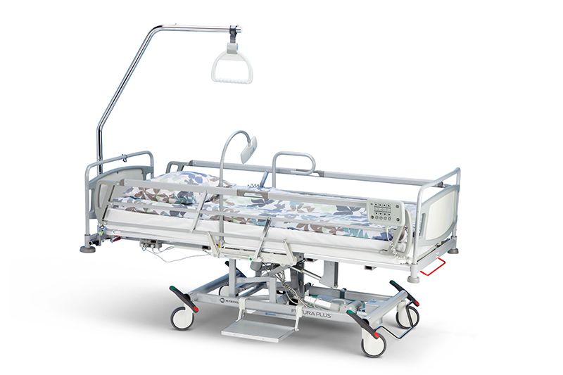
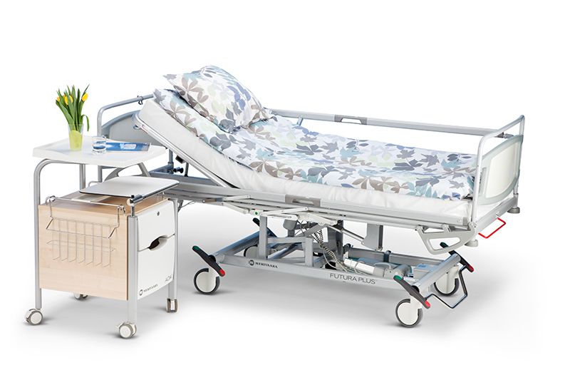
Бестселлер Merivaara, классическая кровать Futura Plus усовершенствована для обеспечения еще большего комфорта и надежности, чем раньше. Новая Futura Plus также соответствует новым стандартам для медицинских кроватей IEC 60601-2-52. Разработанная и изготовленная в Финляндии, это долговечная, выгодная по стоимости больничная кровать.
Кровать доступна в версиях — с 2 или 3 секциями, с электрической или гидравлической регулировкой высоты.
В двухсекционных кроватях регулируются высота и спинная секция, в трехсекционных кроватях регулирются высоты, спинная и ножная секции
Технические характеристики:
- Пульт управления (электрическая модель)
- Основание матраса из ABS-пластика (вентилируемое и съемное)
- Бамперы
- Крепление для фиксации ремней безопасности
- При изменении положения спинной секции кровать и принадлежности не двигаются
- Одновременное перемещение различных частей (например, высоты и спинной секции)
ТЕХНИЧЕСКИЕ ДАННЫЕ
| Модель | Futura Plus, электрическая модель | Futura Plus, гидравлическая модель |
| Свойства | ||
| Длина общая | 2225 мм | 2225 мм |
| Длина ложа | 2001 мм | 2001 мм |
| Ширина общая | 912 мм | 912 мм |
| Ширина ложа | 812 мм | 812 мм |
| Регулировка высоты | 450 — 840 мм | 450 — 840 мм |
| Макс. вес пациента | 170 кг | 170 кг |
| Безопасная рабочая нарузка | 230 кг | 230 кг |
| Тренделенбург | 13 ° | 26 °/12° |
| Антитренделенбург | 6 ° | 12 °/ 6° |
| Регулировка спинной секции | 0 …+ 70 ° | 0 …+ 70 ° |
| Регулировка ножной секции | 0 …- 51 ° (для трехсекционной модели) | 0 …- 38 ° (для трехсекционной модели) |
| Диаметр колес | 150 мм | 150 мм |
| Матрацное основание (секции) | 2 — 3 | 2 — 3 |
| Маркировка СЕ | Да | Да |
| Страна производства | Финляндия | Финляндия |
СПРОСИТЬ ОБ ЭТОМ ПРОДУКТЕ
Другие продукты в этой категории
USER AND MAINTENANCE MANUAL
FUTURA PLUS
o1027a.eps

1GENERAL 5
2 TECHNICAL SPECIFI CATIONS 6
2.1 Identification plate 6
2.1.1 Illustratio n designations 6
2.2 Properties and materials 6
2.2.1 Conditions 6
2.2.2 Classification da t a 7
2.2.3 Dimensions 7
2.2.4 Adjustment rang es 8
2.2.5 S urface material s 8
3PRODUCT USE 9
3.1 Implementation 9
3.1.1 S pecial instructions 9
3.2 Structure and adjustments 10
3.2.1 Central braking sy stem and direct ional castor 10
3.2.2 Height adjustment 10
3.2.3 Leg section adjus tment 10
3.2.4 Trendelenburg a n d anti-Trendelenburg adjustment 10
3.2.5 Back section adjustment. 11
3.2.6 Back section adjustment with foot ped al 11
3.2.7 Po wer adjustment of bac k section adjustment 11
3.2.8 Hand-held control unit operation 12
3.2.9 Back section quick -release 12
3.2.10RTG cassette hold er 12
Compiled by: Mika Similä Type:
Approved by: Päivikki Mikkonen-Kutti Document:
User and maintenance manual Complete: 6.6.2001
2
DO1027.en Version: 00 — 6.6.2001

4CLEANING 13
4.1 Bed cleaning and disinfecting 13
4.1.1 Bed 13
4.1.1.1 Cleaning 13
4.1.1.2 Disinfecting 13
4.1.1.3 Drying 13
4.1.2 Mattress 13
4.1.2.1 Cleaning mattress cover 13
4.1.2.2 Disinfecting mattress cover 13
5 MAINTENANCE AND REPAIR 14
5.1 Preventative maintenance 14
5.1.1 Daily maintenance 14
5.1.2 Annual maintenance 14
5.2 Troubleshooting 15
5.3 Central braking system and castors 16
5.3.1 Central brake 16
5.3.2 Brake adjustment 16
5.4 Hydraulics 17
5.4.1 P ump removal 17
5.4.2 Pedal removal 17
5.4.3 Pedal pad removal 17
5.4.4 Hydraulic pump bleeding 17
5.5 Gas springs 18
5.5.1 Removal of back section gas spring 18
5.5.2 Re moval of gas spring from protector sleeve 18
5.5.3 Removal of Trendelenburg and leg section adjustment gas springs 19
5.6 Replacement of motors and control unit 20
5.6.1 Control unit 20
5.6.2 Removal of back and leg section adjustme nt motors 20
5.7 Connection schematic 21
3

6 SPARE PARTS 22
6.1 Height-adjustable lower frame and lift levers 22
6.2 Fixed-height lower frame and central braking system 23
6.2.1 Height adjuster hy d ra uli c pu mp 24
6.2.2 Height adjust er an d moto r 25
6.3 Gas spring adjusters 26
6.3.1 Le g section adjustment gas spring 27
6.3.2 Tr endelenburg adjustment gas spr ing 28
6.3.3 Back sect ion adjustment gas sprin g 29
6.3.4 Back section adjustment with foot ped al 30
6.4 Electric motor adjusters 31
6.4.1 Back sect ion adjustment motor and quick-release 32
6.5 Mattress bases 33
6.6 Braking and directional castors 35
7RECYCLING 36
7.1 Metals and plastics 36
7.1.1 Gas springs 36
4
1. GENERAL
Dear patient bed owner. The safe and fault-free use and maintenance of the equipment requires careful
adherence to these instructions . When mounting accessories to the eq uipment, the instructions provided
with them must be followed closely. Always keep the instructions for accessories together with this manual.
Warnings and obser vations in this instruction manual are indicated as follows:
WARNING! Please observe in order to ensure patient safety.
NOTE! Please observe in order to avoid causing damage to the equipment or its pa rts.
Must be lubricated during mainten a nce and when replacing parts.
• Warnings and Notes are given on page 9, 11, 12, 15, 16, 21 and 36.
The Futura Plus patient bed meets IEC 601-2-38, IEC 601-1-2 (EMC) and SFS-EN 60601-1 standards.
The bed is a Class I pro duct in accordance with directive 93/42 /E EC ( MD D ), and bears a CE marking based
on this classification.
Intended use
The Merivaara p atien t bed is inten ded for u se in I CU and l ong-t erm t reatmen t wards as wel l as fo r speci alised
applications in emergency and observation wards.
Your Specialist for integrated Medical
Furniture and Equipment Systems.
Merivaara products form an integrated furnishing system
for clinical, hospital and nursing home enviroments. The
comprehensive range of Merivaara products includes
high-quality tools and equipment needed in a variety of
medical procedures.
Merivaara products feature flexible design, turn easily into
ideal working positions and offer high patient comfort.
Daily nursing procedures are readily accommodated by
the safe and easy operation of all Merivaara products.
The comprehensive selection of (available) accessories
make our products ideal for several speciality procedures.
You can get more information on Merivaara products,
from our Sales Office. For matters related to equipment
servicing, please contact the Merivaara After Sales
Department .
5
2. TECHNICAL SPECIFICATIONS
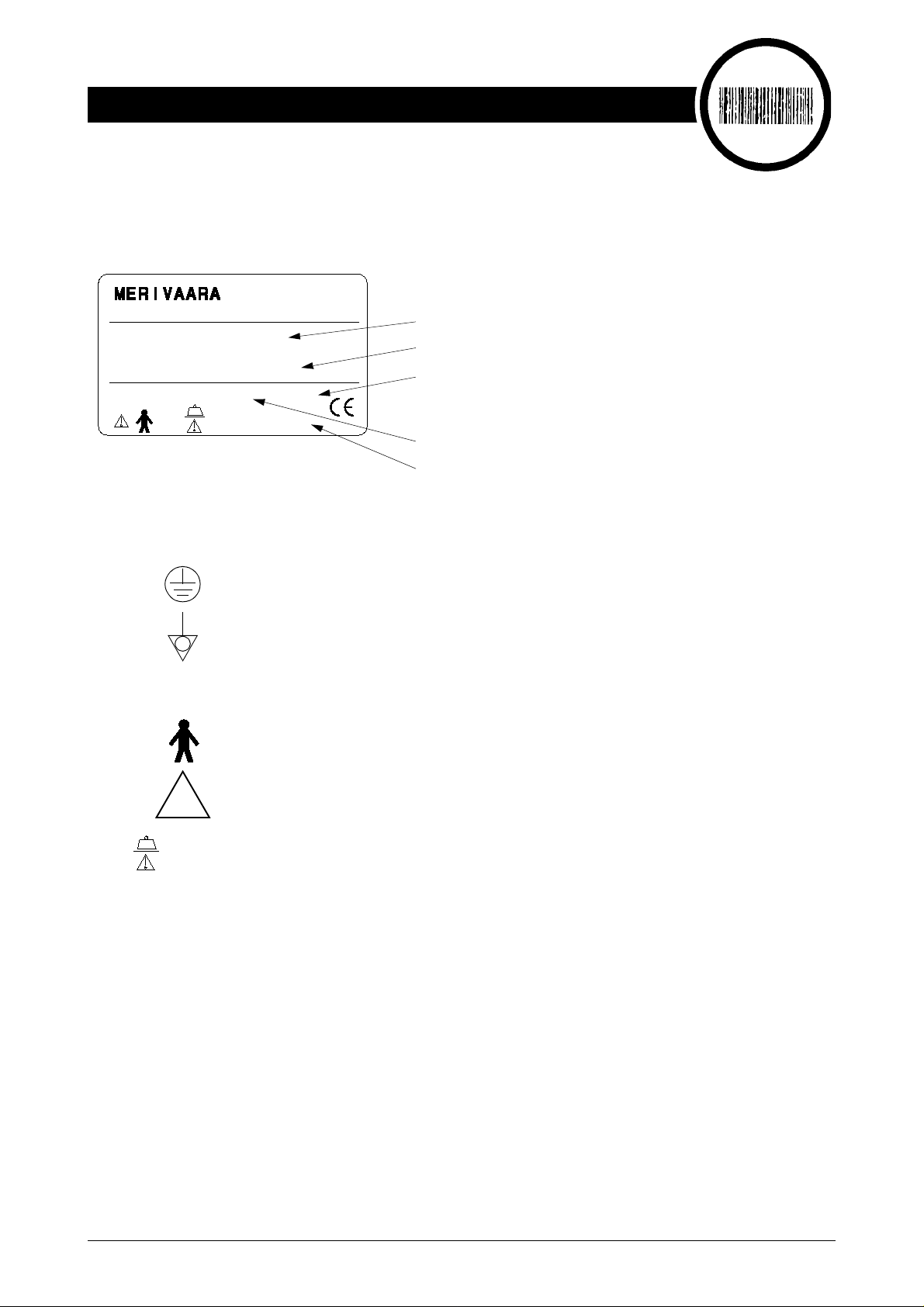
2.1 Identification plate
The identification plate is located underneath the back section.
INSTRUMENTARIUM CORP.
FI-15150 LAHTI
MADE IN FINLAND
MODEL 12345/6789
SERIAL NO 1234-5678910
230 V ~ 50 Hz 250 VA
=180 kg
2.1.1 Illustration designations
ED 10%
IP 54
Protective grounding
Equipotential bonding
AC
B-type connector
Model number
Serial number
Periodic use/ max. 1 min. / 10 min.
Nominal voltage, frequency and input power
Enclosure class
o1027e.eps
o1002h.eps
!
Read instructions
=180 kg
2.2 Properties and materials
2.2.1 Conditions
Ambient temperature +10 … +40 °C
Ambient pressure 700 … 1060 mbar
Relative humidity 30% … 75 %
Transport temperature -10 … +40 °C
Storage temperature +10 … +40 °C
Safe working load
(incl. patient, mattress and accessories) 180 kg
Safe working load (incl. patient, mattress and accessories)
o1027f.eps
6
2.2.2 Classification data
Electric shock protection class I equipment
Degree of electric shock protection B-type equipment
Watertight protec tion watertight eq uipment (IPX4)
Cleaning and disinfecting in section 4.1 on page 13
Combustible an aesthetic gas protection cannot be used together with combustible gases
Function type periodic use
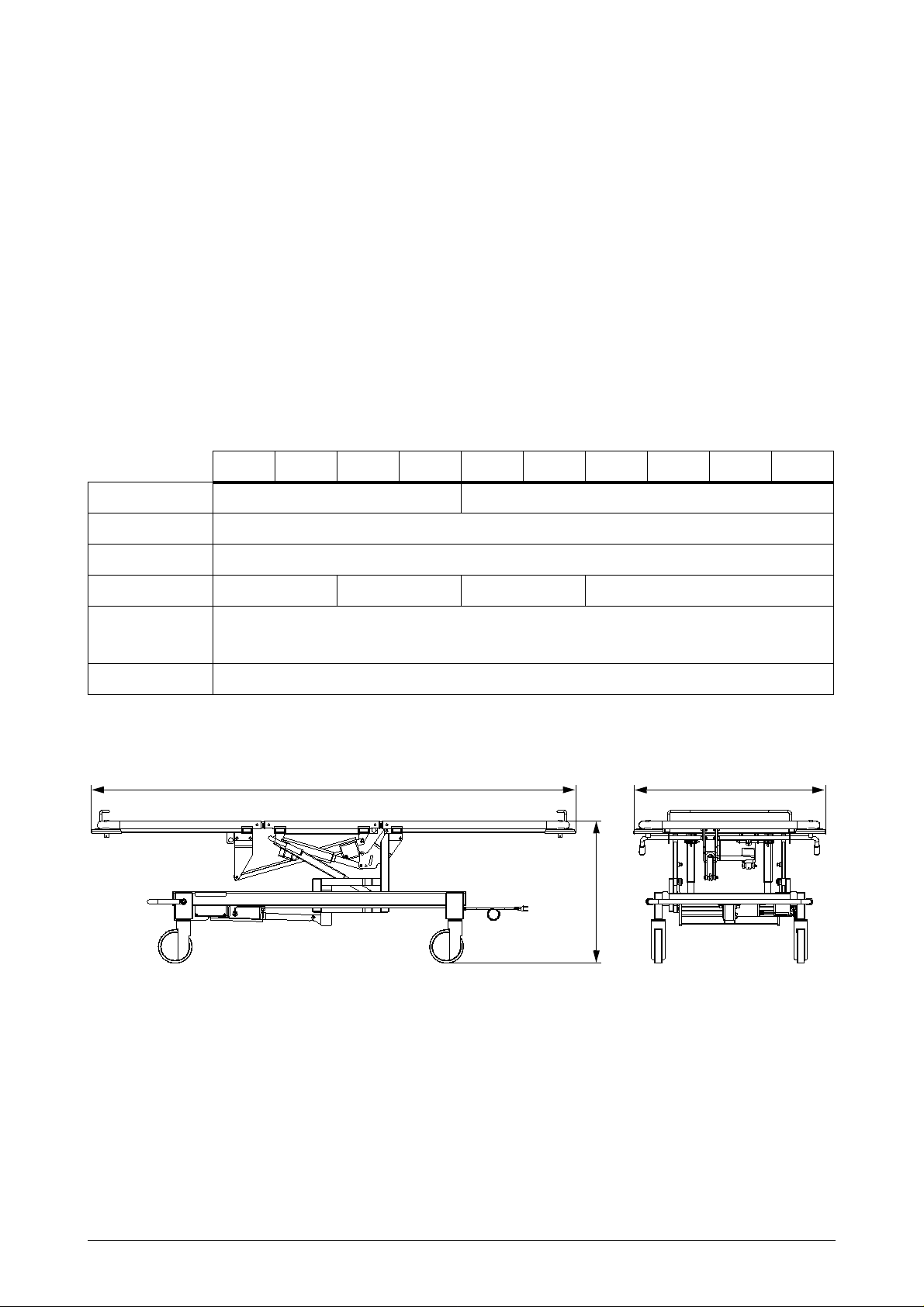
2.2.3 Dimensions
8280 8281 8290 8291 8380 8381 8390 8391 8490 8491
Mattress bases 2-piece 3-piece
Weight kg Depending on the number of bed accessories included: approx. 7 9-91 kg
Length (A) 2135 mm
Width (B) 845 mm 945 mm 845 mm 945 mm
Height (C) Without adjusters: 600 mm, with hydraulic adjuster: 415-810 mm
and with electric adjuster: 440-830 mm
Castors 125 mm
Table 1. Dimensions
A
B
C
o1027b.eps
7
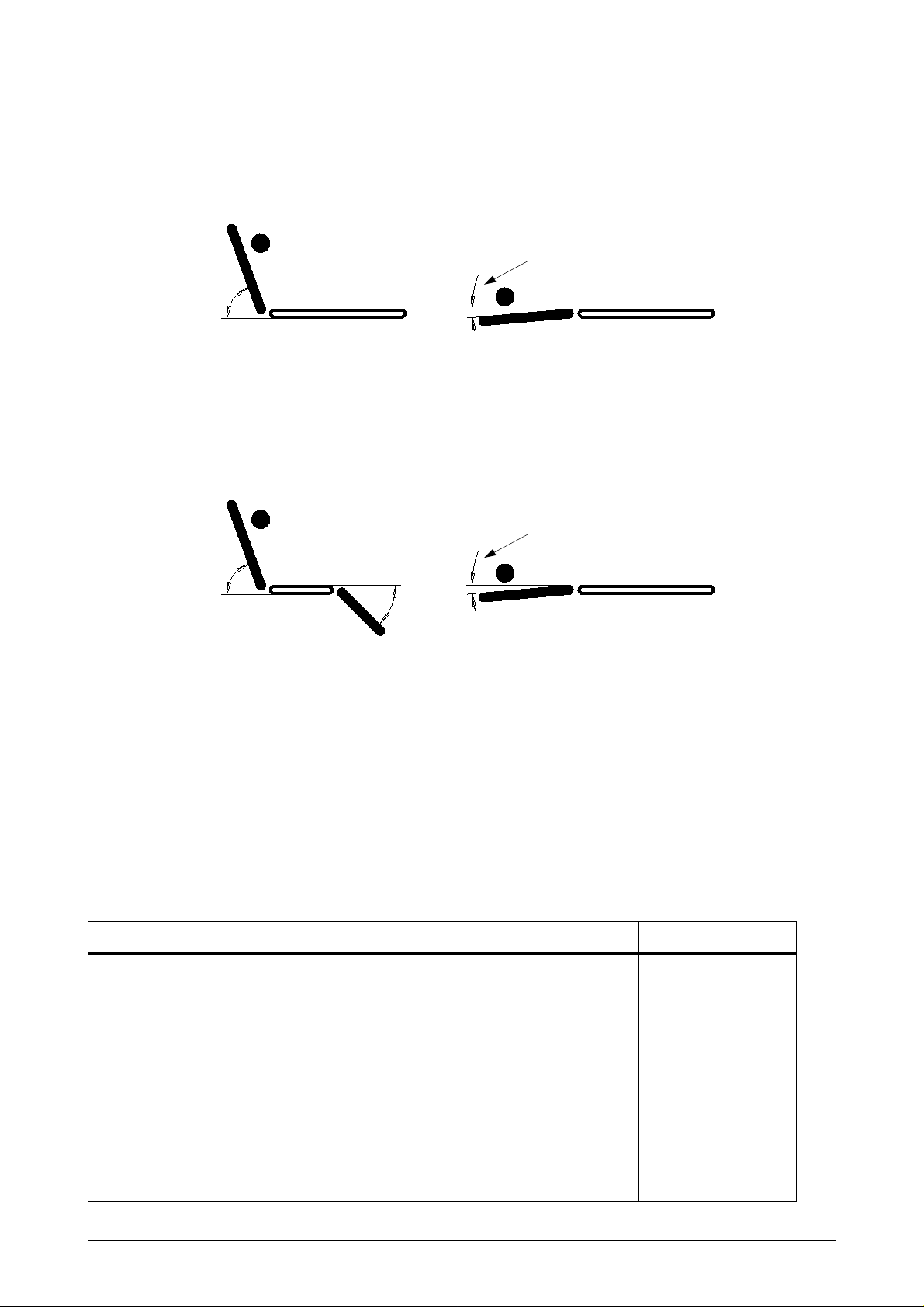
2.2.4 Adjustment ranges
8280 and 8290
Only with gas spring adjuster
65°
Trendelenburg adjustment 26° (height adjustment range 525 … 810)
Anti-Trendelenburg adjustment 12° (height adjustment range 575 … 810)
8281 and 8291
Trendelenburg adjustment 26° (height adjustment range 525 … 830)
Anti-Trendelenburg adjustment 5° (height adjustment range 440 … 830)
8380, 8390 and 8490
65°
5°
Only with gas spring adjuster
5°
45°
Trendelenburg ad juster 26° (height adjustment range 525 … 810)
Anti-Trendelenburg adjuster 12° (height adjustment range 575 … 810)
Leg section adjuster 45° (height adjustment range 755 … 810)
o1027g.epso1027h.eps
8381, 8391 and 8491
Trendelenburg ad juster 26° (height adjustment range 525 … 830)
Anti-Trendelenburg adjuster 5° (height adjustment range 440 … 830)
Leg section adjuster 48° (height adjustment range 765 … 830)
2.2.5 Surface materials
Surface materials FUTURA PLUS
Epoxy-powder coat, frame parts X
Paint, base plates X
Chroming, pedal bar, fram e parts X
ABS (acrylonitrile/butadiene/styrene), storage boxes X
PP (polypropylene) bumper rollers, rail mounting brackets X
PA 6 (polyamide) mattress base joint, handles, motors X
TPE (thermoplastic elastomer) pedal pad X
PPE/HIPS (modified polyphenylene ether/polystyrene) hand-held control unit X
8

3. PRODUCT US E
3.1 Implementation
The patient bed is packaged pre-assembled. Check for damages that may have been caused during
transport. If the bed has been in cold temperatures, allow to warm up to room temperature before connecting
power. Cardboard packing materials should be recycled. Wood and plastic are energy waste.
3.1.1 Special instructions
WARNING!
Ensure that the power lead is not trapped between
cut the lead. When adjusting the mattress base into the Trendelenburg or anti-Trendelenburg position,
ensure that the lead is not caught between the mattress base and base frame. Damaged power leads can
result in electric shock!
The maximum load capacity of the bed is 180 kg. Only one person may be on the bed when useing
electrically controlled adjustments.
Before moving the bed, put the mattress base into the mid-position.
Always move the bed over thresholds (or similar obstacles) with the leg sec tion in front
the castors and other mec hanical parts to a minimum.
Keep the mattress base of unattended
Whenever adjusting the bed
caught between the bed and accessories or between the moving parts of the bed.
, ensure that the patient’s fingers, hands or other parts of the body are not
beds in the lower position. (IEC 60601-2-38)
the moving parts of the bed, as this may expose or
, to keep impacts on
NOTE!
Do not operate the motors for more than one minute at a time (max. 1 min.). Continuous repetition of
movements may overload and damage the motor.
Ensure that the hand-held contro l unit wire does not get caught between moving parts of the bed, as their
movement may expose or cut the wire. An exposed or cut hand-held control unit wire is not life-threatening,
as it operates on a 24 V safety voltage. When adjusting the mattress base into the Trendelenburg or antiTrendelenburg position, ensure that the wire is not caught between the ma ttress base and base frame.
Use potential equalization set (asseccory 128005102) with patient monitoring equipment.
9
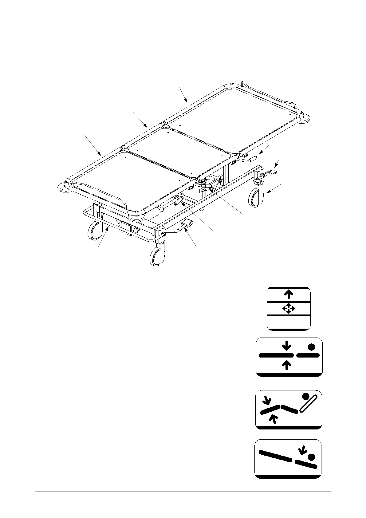
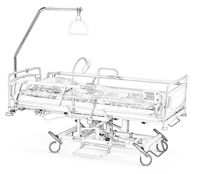
3.2 Structure and adjustments
Seat section
Leg section
Back section
Back section handle
Spare brake
pedal (both sides)
Directional castor
Trendelenburg and
Anti-Trendelenburg ha ndle
Leg section handle
Central brake pedal
Height adjuster pedal
Pictured: Futura Plus 8380
3.2.1 Central braking system and directional castor
When the pedal is up, the directio nal castor is locked in its steering position.
When the peda l i s in the middle position, all castors wi ll turn.
When the pedal is down, all wheels will lock.
3.2.2 Height adjustment
Pressing the height adjuster pedal down will raise the mattress base.
Lifting the ped a l will lower the mattress base.
The adjustment rang e is 370 mm.
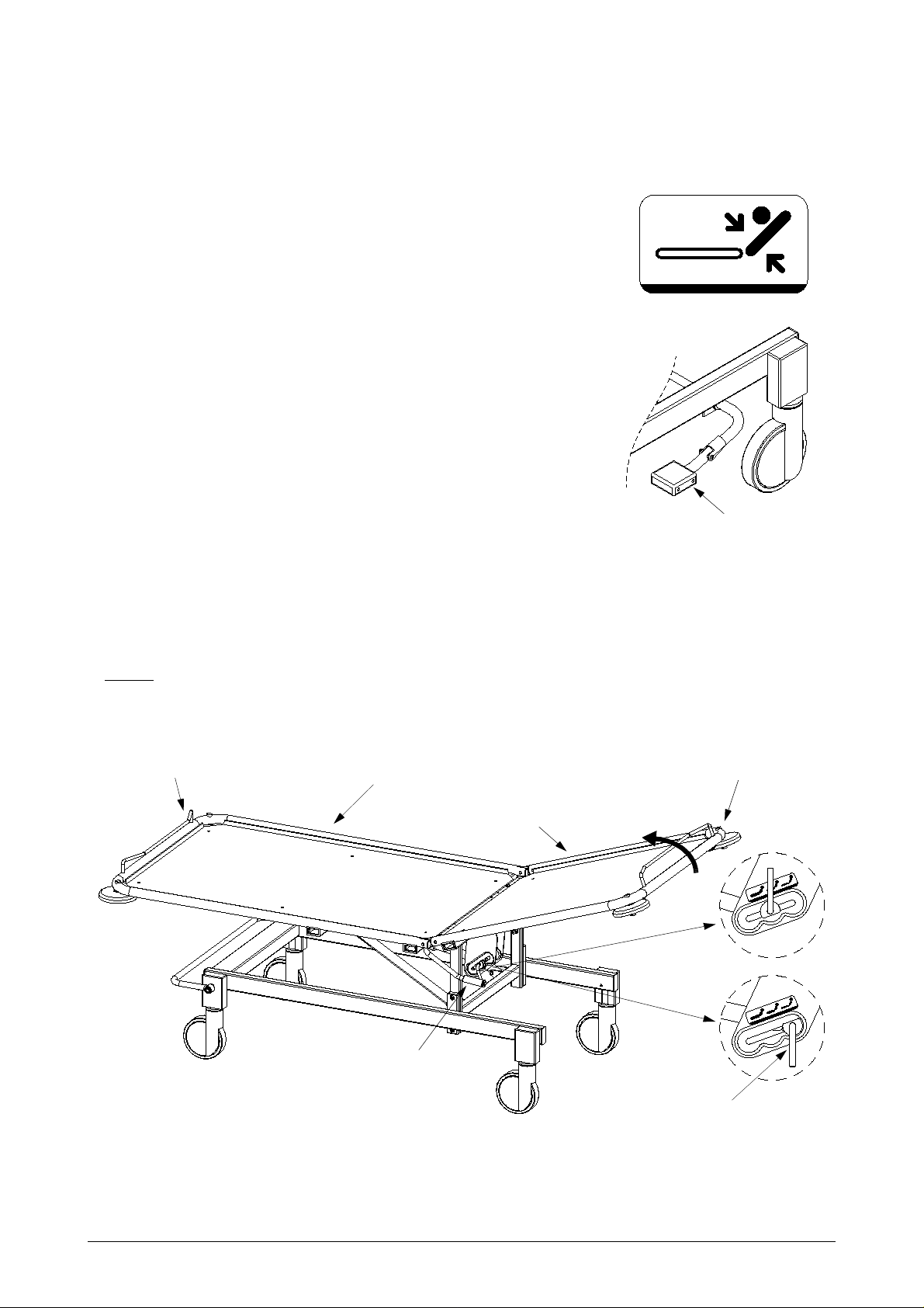
3.2.3 Leg section adjustment
Turn the adjuster bar and support the leg section end tubing
with your other hand.
STOP
o1027c.eps
p4-9288.eps
p4-9286v.eps
3.2.4 Trendelenburg and anti-Trendelenburg adjustment
Turn the adjuster bar and a djust the leg section t rolley end tubing
with your other hand.
10
p4-9285v.eps
p4-9281v.eps
3.2.5 Back section adjustment.
Turn the back section adju ster bar and support the back section end
with your other hand
Check the power of the back section adjustment in sectio n 3.2.7 on page 11
as shown.
3.2.6 Back section adjustment with foot pedal
Depress pedal and support the back or leg section end
with your free hand.
Check the power of the back section
adjustment in section 3.2.7 on page 11 as shown.
p4-9284o.eps
3.2.7 Power adjustment of back section adjustment
Adjuster pedal
1. Bring the back section to a semi-sitting position.
2. Manually support the back section at the mattress ba se end.
3. Turn the adjuster bar one half turn.
4. Support the back section with your other hand and move the adjuster bar into the desired position.
5. Lock the adjuster bar by turning it one half turn. The adjuster bar should be
FULLY
lowered, whenever using the bed.
WARNING!The patient must not lean on the back section when adjusting.
Leg section
trolley end
Leg section
Back section
trolley end
1.
Back section
3.
o1027i.eps
Pictured: Futura Plus 8280
Back section
handle
11
4-5.
Adjuster bar
o1027d.eps
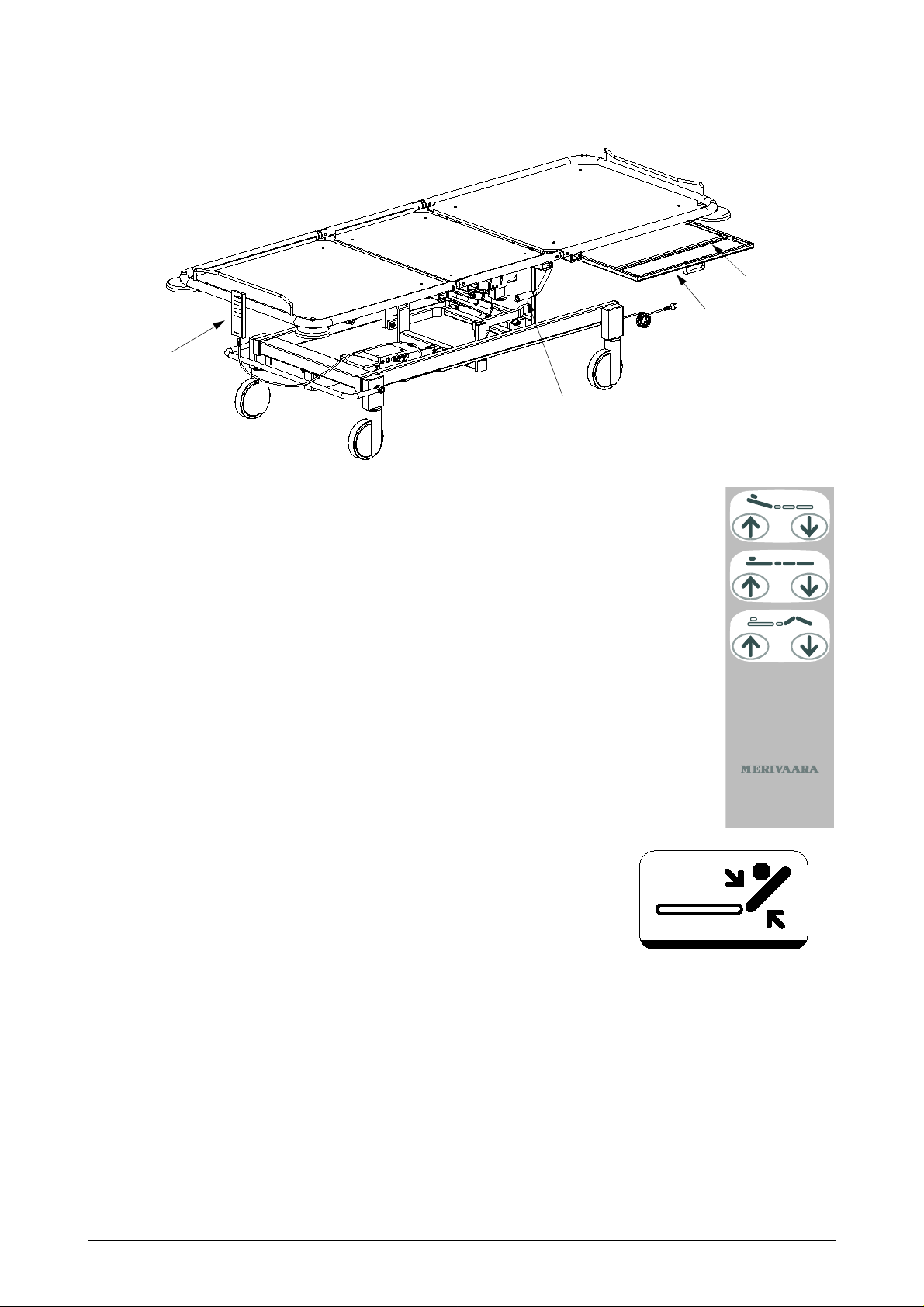
Hand-held
control unit
Adjuster bar
RTG cassette
holder
Back section quick-release
Pictured: Futura Plus 8491
3.2.8 Hand -held control unit operation
Adjustments are made electrically by pressing the buttons on the hand-held
control unit. Press the button of the function you desire . The selected
function will continue until you release the button or the outermost position is
reached. If desired, you can operate several functions at the same time. If the
function is interrupted when do ing so, the overload protector has been
tripped. Release all buttons and perform each function one at a t ime.
NOTE! Do not operate the motors for more than one minute at a time.
Continuous repetition of movements may overload and
damage the motor.
3.2.9 Back section quick-release
• Hold the back section with your r ight hand and
the red quick-release lever with your left.
o1027j.eps
Back section
adjustment
Height
adjustment
Leg section
adjustment
o1011f.wmf
• Push the quick-release lever down until the back section can
move freely.
WARNING! When using the quick-release lever, you must hold the back section
so that it does not drop too quickly.
3.2.10RTG cassette holder
• Move the cassette rack to the side.
• Mount the RTG cassette on the ca ssette rack and lock i t with the adjuster bar.
The bed frame tubing, cassette rack and adjuster bars all have measuring scales aligned with each other,
which can be used to correctly place the cassette rack.
12
p4-9284o.eps
 Loading…
- Manuals
- Brands
- Merivaara Manuals
- Medical Equipment
- FUTURA PLUS
- User and maintenance manual
-
Bookmarks
Quick Links
USER AND MAINTENANCE MANUAL
FUTURA PLUS
Related Manuals for Merivaara FUTURA PLUS
Summary of Contents for Merivaara FUTURA PLUS
-
Page 1
USER AND MAINTENANCE MANUAL FUTURA PLUS… -
Page 2
GENERAL TECHNICAL SPECIFICATIONS 2.1 Identification plate 2.1.1 Illustration designations 2.2 Properties and materials 2.2.1 Conditions 2.2.2 Classification data 2.2.3 Dimensions 2.2.4 Adjustment ranges 2.2.5 Surface materials PRODUCT USE 3.1 Implementation 3.1.1 Special instructions 3.2 Structure and adjustments 3.2.1 Central braking system and directional castor 3.2.2 Height adjustment 3.2.3 Leg section adjustment 3.2.4 Trendelenburg and anti-Trendelenburg adjustment… -
Page 3
CLEANING 4.1 Bed cleaning and disinfecting 4.1.1 Bed 4.1.1.1 Cleaning 4.1.1.2 Disinfecting 4.1.1.3 Drying 4.1.2 Mattress 4.1.2.1 Cleaning mattress cover 4.1.2.2 Disinfecting mattress cover MAINTENANCE AND REPAIR 5.1 Preventative maintenance 5.1.1 Daily maintenance 5.1.2 Annual maintenance 5.2 Troubleshooting 5.3 Central braking system and castors 5.3.1 Central brake 5.3.2 Brake adjustment 5.4 Hydraulics… -
Page 4
SPARE PARTS 6.1 Height-adjustable lower frame and lift levers 6.2 Fixed-height lower frame and central braking system 6.2.1 Height adjuster hydraulic pump 6.2.2 Height adjuster and motor 6.3 Gas spring adjusters 6.3.1 Leg section adjustment gas spring 6.3.2 Trendelenburg adjustment gas spring 6.3.3 Back section adjustment gas spring 6.3.4 Back section adjustment with foot pedal 6.4 Electric motor adjusters… -
Page 5
The bed is a Class I product in accordance with directive 93/42/EEC (MDD), and bears a CE marking based on this classification. Intended use The Merivaara patient bed is intended for use in ICU and long-term treatment wards as well as for specialised applications in emergency and observation wards. Your Specialist for integrated Medical Furniture and Equipment Systems. -
Page 6
2. TECHNICAL SPECIFICATIONS 2.1 Identification plate The identification plate is located underneath the back section. FI-15150 LAHTI MADE IN FINLAND INSTRUMENTARIUM CORP. Model number MODEL 12345/6789 Serial number SERIAL NO 1234-5678910 Periodic use/ max. 1 min./ 10 min. 230 V ~ 50 Hz 250 VA ED 10% =180 kg IP 54… -
Page 7
2.2.2 Classification data Electric shock protection class I equipment Degree of electric shock protection B-type equipment Watertight protection watertight equipment (IPX4) Cleaning and disinfecting in section 4.1 on page 13 Combustible anaesthetic gas protection cannot be used together with combustible gases Function type periodic use 2.2.3 Dimensions… -
Page 8
5° (height adjustment range 440 … 830) Leg section adjuster 48° (height adjustment range 765 … 830) 2.2.5 Surface materials Surface materials FUTURA PLUS Epoxy-powder coat, frame parts Paint, base plates Chroming, pedal bar, frame parts ABS (acrylonitrile/butadiene/styrene), storage boxes… -
Page 9
3. PRODUCT USE 3.1 Implementation The patient bed is packaged pre-assembled. Check for damages that may have been caused during transport. If the bed has been in cold temperatures, allow to warm up to room temperature before connecting power. Cardboard packing materials should be recycled. Wood and plastic are energy waste. 3.1.1 Special instructions WARNING! Ensure that the power lead is not trapped between the moving parts of the bed, as this may expose or… -
Page 10
Leg section handle Central brake pedal Height adjuster pedal Pictured: Futura Plus 8380 3.2.1 Central braking system and directional castor When the pedal is up, the directional castor is locked in its steering position. When the pedal is in the middle position, all castors will turn. -
Page 11
5. Lock the adjuster bar by turning it one half turn. The adjuster bar should be FULLY lowered, whenever using the bed. WARNING!The patient must not lean on the back section when adjusting. Leg section Back section Leg section trolley end trolley end Back section 4-5. Back section handle Pictured: Futura Plus 8280 Adjuster bar… -
Page 12
RTG cassette holder Hand-held control unit Back section quick-release Pictured: Futura Plus 8491 3.2.8 Hand-held control unit operation Back section adjustment Adjustments are made electrically by pressing the buttons on the hand-held control unit. Press the button of the function you desire. The selected… -
Page 13
4. CLEANING 4.1 Bed cleaning and disinfecting 4.1.1 Bed 4.1.1.1 Cleaning Remove all accessories. Clean by wiping down with a lightly alkaline detergent (pH 7-8). 4.1.1.2 Disinfecting Wipe using, for example, a 3% chloramine-based disinfectant (Klorilli) or similar cleaning agent. 4.1.1.3 Drying Dry thoroughly by wiping down immediately after cleaning or disinfecting. -
Page 14
5. MAINTENANCE AND REPAIR 5.1 Preventative maintenance Mark the date taken into use next to the type badge on the patient bed back section. The date will provide a reference for annual servicing. Remember to mark the patient bed with the date when performing the annual servicing, so that the following service date will not require a separate reminder. -
Page 15
5.2 Troubleshooting Problem Cause Repair Mattress base will not rise. • Oil level low. Bleed pump. • Air in the hydraulic system. Mattress base will not lower • Air in the hydraulic system. Bleed pump. properly Mattress base not • Faulty valve. -
Page 16
5.3 Central braking system and castors 5.3.1 Central brake • Put brake pedal into free position (1) (pedal centred). • Remove screw (2). • Pull pedal bar (1) out from lever (3). • Remove end plug (4). • Loosen retaining screw (5) with a 3 mm Allen key. •… -
Page 17
5.4 Hydraulics 5.4.1 Pump removal • Bring mattress base into its upright position. • Remove circlip (1). • Remove tap pivot pin (2) and plastic bushings (3). • Loosen nuts (4) and remove screws (5) from both sides. • Remove limiters (6). •… -
Page 18
5.5 Gas springs Leg section gas spring Trendelenburg gas springs (2 pcs) Back section gas spring 5.5.1 Removal of back section gas spring Put gas spring adjuster handle into centre position. Bring back section into upright position and support with, for example, a nightstand. •… -
Page 19
5.5.3 Removal of Trendelenburg and leg section adjustment gas springs Bring bed into Trendelenburg position and support with, for example, a nightstand. • Remove circlip (1). • Using a mandrel, tap out tap pivot pin (2). • Remove plastic bushings (3). •… -
Page 20
5.6 Replacement of motors and control unit 5.6.1 Control unit • Bring mattress base into its upright position and remove the power lead from the wall outlet. • Loosen the screw (1) using a TORX wrench (T20). • Pull the control unit (2) toward the motor arm. -
Page 21
5.7 Connection schematic NOTE! In order to avoid accidents, always remember to disconnect the power lead before servicing! Power lead Hand-held Back section adjuster motor control unit 4 3 2 1 Control unit Leg section adjuster motor Height adjuster motor… -
Page 22
6. SPARE PARTS 6.1 Height-adjustable lower frame and lift levers Number of parts in assembly Part Code Part name Additional information Height adjustment See section 6.2.2 on page 25. 709851 Bushing A4540000 Bearing retainer 70645 Allen screw SFS 2219-M10x25 Central braking system See section 6.2 on page 23. -
Page 23
6.2 Fixed-height lower frame and central braking system Number of parts in assembly Part Code Part name Additional information A2400100 Pedal 710219 Side rail plug Grey Castor See section 6.6 on page 35. 70530 Screw SFS 2759-4.2×1.3 A4724500 Axle A4724700 Fixing lever 7107069 Protective housing… -
Page 24
6.2.1 Height adjuster hydraulic pump Number of parts in assembly Part Code Part name Additional information A2334500 Mounting case 70409 Limiter 707410 Nyloc DIN 985-M5 70777 Washer DIN 125-A5.5 70452 Screw SFS 2976-M5x12 70814 Spring pin DIN 1481-8×32 A2404301 Pedal bar Bed width 845 mm A2413300 Pedal bar… -
Page 25
6.2.2 Height adjuster and motor Number of parts in assembly Part Code Part name Additional information A2474400 Mounting case 71336063 Control unit for 2 motors CB09LO-2T-24, IP 54, 230 V 71336066 Control unit for 3 motors CB09LO-3T-24, IP 54, 230 V 71336067 Control unit for 2-3 motors CB09LO-3BT-24, IP 66, 230 V… -
Page 26
6.3 Gas spring adjusters See section 6.3.1 on page 27. ** See section 6.3.2 on page 28. *** See section 6.3.3 on page 29. Number of parts in assembly Part Code Part name Additional information 70743 Nyloc DIN 985-M8 70772 Star washer DIN 6978-J8.2 70634… -
Page 27
6.3.1 Leg section adjustment gas spring Number of parts in assembly Part Code Part name Additional information A4375600 Slide bearing 70792 Retaining ring DIN 471-10×1 A4541500 Pivot pin 70623 Allen screw SFS 2219-M6x16 78006 Washer sleeve 70742 Nyloc DIN 985-M6 A3490600 Cross bar A45429B00… -
Page 28
6.3.2 Trendelenburg adjustment gas spring Number of parts in assembly Part Code Part name Additional information A34012A00 Support bar A202000 Adjuster bar A3357500 Ram mount A3357400 Mounting bracket M10x1 A2474501 Stopper bushing 712583 Gas spring 180 mm/420N A33573 Protective sleeve Request colour. -
Page 29
6.3.3 Back section adjustment gas spring Number of parts in assembly Part Code Part name Additional information A3357500 Ram mount A3357400 Mounting bracket M10x1 71260 Gas spring 180 mm/720N A33573 Protective sleeve Request colour. A33573A Protective sleeve Request colour. Only with foot release. 709781 Bearing retainer 706912… -
Page 30
6.3.4 Back section adjustment with foot pedal Number of parts in assembly Part Code Part name Additional information 709772 Pedal pad 709772 Plug 70810 Spring pin DIN 1481-6×40 A4980400 Pedal bar 70992 Cover plug 70742 DIN 985-M6 706374 Screw ISO 7380-M6x32 A4980300 Pedal bar Left side… -
Page 31
6.4 Electric motor adjusters See section 6.4.1 on page 32. Number of parts in assembly Part Code Part name Additional information 70792 Retaining ring DIN 471-10×1 A4381800 Pivot pin 71335455 Leg section motor LA31.2M-200-24-301, IP 54 71335451 Leg section motor LA31.2M-200-24-301, IP 66 70634 Allen screw… -
Page 32
6.4.1 Back section adjustment motor and quick-release Number of parts in assembly Part Code Part name Additional information 71335455 Back section motor LA31.2M-200-24-301, IP 54 71335451 Back section motor LA31.2M-200-24-301, IP 66 71335449 Back section motor LA31.2Q1M-150-24-005, IP 66 70792 Retaining ring DIN 471-10×1 A4381800… -
Page 33
6.5 Mattress bases NOTE! the position of the spring pins Number of parts in assembly Part Code Part name Additional information 70962 Pivot plug half-piece A4331700 Pivot bar 70815 Spring pin DIN 1481-10×32 709782 Rail mounting bracket 709752 Bumper reel A24008 Mattress base Request colour. -
Page 34
Mattress bases NOTE! the position of the spring pins Number of parts in assembly Part Code Part name Additional information 70962 Pivot plug half-piece A4331700 Pivot bar 70815 Spring pin DIN 1481-10×32 709782 Rail mounting bracket 709752 Bumper reel 715121 Handle 70530 Screw… -
Page 35
6.6 Braking and directional castors Part Code Part name Additional information 712405 Brake castor Ø 125 712406 Directional castor Ø 125 7123232 Brake castor Ø 150 7123233 Directional castor Ø 150 7123211 Brake castor Ø 125 7123111 Directional castor Ø 125 712479 Brake castor Ø… -
Page 36
7. RECYCLING 7.1 Metals and plastics When disposing of a patient bed or replacing any of its parts, check the recyclability of each item. A majority of the metal used on the patient bed is steel. There are also zinc and aluminium castings and brass bushings. -
Page 37
NOTES… -
Page 40
Delivery address: Invoicing address: Mark / reference: Mark / reference: Orderer: Telephone: Order date: Transport mode: Pcs. Part Code Part name Information: Merivaara Corp. Telephone: +358 3 3394 6152 Puustellintie 2 Fax: +358 3 3394 6249 FIN — 15150 LAHTI, FINLAND…
Популярная и классическая модель
Главные характеристики:
1. Возможность выбора кровати с электрической или гидравлической регулировкой высоты
2. Эргономичное регулирование спинной секции
2. Новая улучшенная конструкция рамы
3. Удобная и надежная базовая больничная функциональная кровать
Общая информация
Бестселлер Merivaara, классическая кровать Futura Plus усовершенствована для обеспечения еще большего комфорта и надежности, чем раньше. Новая Futura Plus также соответствует новым стандартам для медицинских кроватей IEC 60601-2-52. Разработанная и изготовленная в Финляндии, это долговечная, выгодная по стоимости больничная кровать.
Кровать доступна в версиях — с 2 или 3 секциями, с электрической или гидравлической регулировкой высоты.
В двухсекционных кроватях регулируются высота и спинная секция, в трехсекционных кроватях регулирются высоты, спинная и ножная секции
Технические характеристики:
- Пульт управления (электрическая модель)
- Основание матраса из ABS-пластика (вентилируемое и съемное)
- Бамперы
- Крепление для фиксации ремней безопасности
- При изменении положения спинной секции кровать и принадлежности не двигаются
- Одновременное перемещение различных частей (например, высоты и спинной секции)
ТЕХНИЧЕСКИЕ ДАННЫЕ
| Модель | Futura Plus, электрическая модель | Futura Plus, гидравлическая модель |
| Свойства | ||
| Длина общая | 2225 мм | 2225 мм |
| Длина ложа | 2001 мм | 2001 мм |
| Ширина общая | 912 мм | 912 мм |
| Ширина ложа | 812 мм | 812 мм |
| Регулировка высоты | 450 — 840 мм | 450 — 840 мм |
| Макс. вес пациента | 170 кг | 170 кг |
| Безопасная рабочая нарузка | 230 кг | 230 кг |
| Тренделенбург | 13 ° | 26 °/12° |
| Антитренделенбург | 6 ° | 12 °/ 6° |
| Регулировка спинной секции | 0 …+ 70 ° | 0 …+ 70 ° |
| Регулировка ножной секции | 0 …- 51 ° (для трехсекционной модели) | 0 …- 38 ° (для трехсекционной модели) |
| Диаметр колес | 150 мм | 150 мм |
| Матрацное основание (секции) | 2 — 3 | 2 — 3 |
| Маркировка СЕ | Да | Да |
| Страна производства | Финляндия | Финляндия |
СПРОСИТЬ ОБ ЭТОМ ПРОДУКТЕ
Другие продукты в этой категории
Loading…
USER AND MAINTENANCE MANUAL
FUTURA PLUS
o1027a.eps
1GENERAL 5
2 TECHNICAL SPECIFI CATIONS 6
2.1 Identification plate 6
2.1.1 Illustratio n designations 6
2.2 Properties and materials 6
2.2.1 Conditions 6
2.2.2 Classification da t a 7
2.2.3 Dimensions 7
2.2.4 Adjustment rang es 8
2.2.5 S urface material s 8
3PRODUCT USE 9
3.1 Implementation 9
3.1.1 S pecial instructions 9
3.2 Structure and adjustments 10
3.2.1 Central braking sy stem and direct ional castor 10
3.2.2 Height adjustment 10
3.2.3 Leg section adjus tment 10
3.2.4 Trendelenburg a n d anti-Trendelenburg adjustment 10
3.2.5 Back section adjustment. 11
3.2.6 Back section adjustment with foot ped al 11
3.2.7 Po wer adjustment of bac k section adjustment 11
3.2.8 Hand-held control unit operation 12
3.2.9 Back section quick -release 12
3.2.10RTG cassette hold er 12
Compiled by: Mika Similä Type:
Approved by: Päivikki Mikkonen-Kutti Document:
User and maintenance manual Complete: 6.6.2001
2
DO1027.en Version: 00 — 6.6.2001
4CLEANING 13
4.1 Bed cleaning and disinfecting 13
4.1.1 Bed 13
4.1.1.1 Cleaning 13
4.1.1.2 Disinfecting 13
4.1.1.3 Drying 13
4.1.2 Mattress 13
4.1.2.1 Cleaning mattress cover 13
4.1.2.2 Disinfecting mattress cover 13
5 MAINTENANCE AND REPAIR 14
5.1 Preventative maintenance 14
5.1.1 Daily maintenance 14
5.1.2 Annual maintenance 14
5.2 Troubleshooting 15
5.3 Central braking system and castors 16
5.3.1 Central brake 16
5.3.2 Brake adjustment 16
5.4 Hydraulics 17
5.4.1 P ump removal 17
5.4.2 Pedal removal 17
5.4.3 Pedal pad removal 17
5.4.4 Hydraulic pump bleeding 17
5.5 Gas springs 18
5.5.1 Removal of back section gas spring 18
5.5.2 Re moval of gas spring from protector sleeve 18
5.5.3 Removal of Trendelenburg and leg section adjustment gas springs 19
5.6 Replacement of motors and control unit 20
5.6.1 Control unit 20
5.6.2 Removal of back and leg section adjustme nt motors 20
5.7 Connection schematic 21
3
6 SPARE PARTS 22
6.1 Height-adjustable lower frame and lift levers 22
6.2 Fixed-height lower frame and central braking system 23
6.2.1 Height adjuster hy d ra uli c pu mp 24
6.2.2 Height adjust er an d moto r 25
6.3 Gas spring adjusters 26
6.3.1 Le g section adjustment gas spring 27
6.3.2 Tr endelenburg adjustment gas spr ing 28
6.3.3 Back sect ion adjustment gas sprin g 29
6.3.4 Back section adjustment with foot ped al 30
6.4 Electric motor adjusters 31
6.4.1 Back sect ion adjustment motor and quick-release 32
6.5 Mattress bases 33
6.6 Braking and directional castors 35
7RECYCLING 36
7.1 Metals and plastics 36
7.1.1 Gas springs 36
4
1. GENERAL
Dear patient bed owner. The safe and fault-free use and maintenance of the equipment requires careful
adherence to these instructions . When mounting accessories to the eq uipment, the instructions provided
with them must be followed closely. Always keep the instructions for accessories together with this manual.
Warnings and obser vations in this instruction manual are indicated as follows:
WARNING! Please observe in order to ensure patient safety.
NOTE! Please observe in order to avoid causing damage to the equipment or its pa rts.
Must be lubricated during mainten a nce and when replacing parts.
• Warnings and Notes are given on page 9, 11, 12, 15, 16, 21 and 36.
The Futura Plus patient bed meets IEC 601-2-38, IEC 601-1-2 (EMC) and SFS-EN 60601-1 standards.
The bed is a Class I pro duct in accordance with directive 93/42 /E EC ( MD D ), and bears a CE marking based
on this classification.
Intended use
The Merivaara p atien t bed is inten ded for u se in I CU and l ong-t erm t reatmen t wards as wel l as fo r speci alised
applications in emergency and observation wards.
Your Specialist for integrated Medical
Furniture and Equipment Systems.
Merivaara products form an integrated furnishing system
for clinical, hospital and nursing home enviroments. The
comprehensive range of Merivaara products includes
high-quality tools and equipment needed in a variety of
medical procedures.
Merivaara products feature flexible design, turn easily into
ideal working positions and offer high patient comfort.
Daily nursing procedures are readily accommodated by
the safe and easy operation of all Merivaara products.
The comprehensive selection of (available) accessories
make our products ideal for several speciality procedures.
You can get more information on Merivaara products,
from our Sales Office. For matters related to equipment
servicing, please contact the Merivaara After Sales
Department .
5
2. TECHNICAL SPECIFICATIONS
2.1 Identification plate
The identification plate is located underneath the back section.
INSTRUMENTARIUM CORP.
FI-15150 LAHTI
MADE IN FINLAND
MODEL 12345/6789
SERIAL NO 1234-5678910
230 V ~ 50 Hz 250 VA
=180 kg
2.1.1 Illustration designations
ED 10%
IP 54
Protective grounding
Equipotential bonding
AC
B-type connector
Model number
Serial number
Periodic use/ max. 1 min. / 10 min.
Nominal voltage, frequency and input power
Enclosure class
o1027e.eps
o1002h.eps
!
Read instructions
=180 kg
2.2 Properties and materials
2.2.1 Conditions
Ambient temperature +10 … +40 °C
Ambient pressure 700 … 1060 mbar
Relative humidity 30% … 75 %
Transport temperature -10 … +40 °C
Storage temperature +10 … +40 °C
Safe working load
(incl. patient, mattress and accessories) 180 kg
Safe working load (incl. patient, mattress and accessories)
o1027f.eps
6
2.2.2 Classification data
Electric shock protection class I equipment
Degree of electric shock protection B-type equipment
Watertight protec tion watertight eq uipment (IPX4)
Cleaning and disinfecting in section 4.1 on page 13
Combustible an aesthetic gas protection cannot be used together with combustible gases
Function type periodic use
2.2.3 Dimensions
8280 8281 8290 8291 8380 8381 8390 8391 8490 8491
Mattress bases 2-piece 3-piece
Weight kg Depending on the number of bed accessories included: approx. 7 9-91 kg
Length (A) 2135 mm
Width (B) 845 mm 945 mm 845 mm 945 mm
Height (C) Without adjusters: 600 mm, with hydraulic adjuster: 415-810 mm
and with electric adjuster: 440-830 mm
Castors 125 mm
Table 1. Dimensions
A
B
C
o1027b.eps
7
2.2.4 Adjustment ranges
8280 and 8290
Only with gas spring adjuster
65°
Trendelenburg adjustment 26° (height adjustment range 525 … 810)
Anti-Trendelenburg adjustment 12° (height adjustment range 575 … 810)
8281 and 8291
Trendelenburg adjustment 26° (height adjustment range 525 … 830)
Anti-Trendelenburg adjustment 5° (height adjustment range 440 … 830)
8380, 8390 and 8490
65°
5°
Only with gas spring adjuster
5°
45°
Trendelenburg ad juster 26° (height adjustment range 525 … 810)
Anti-Trendelenburg adjuster 12° (height adjustment range 575 … 810)
Leg section adjuster 45° (height adjustment range 755 … 810)
o1027g.epso1027h.eps
8381, 8391 and 8491
Trendelenburg ad juster 26° (height adjustment range 525 … 830)
Anti-Trendelenburg adjuster 5° (height adjustment range 440 … 830)
Leg section adjuster 48° (height adjustment range 765 … 830)
2.2.5 Surface materials
Surface materials FUTURA PLUS
Epoxy-powder coat, frame parts X
Paint, base plates X
Chroming, pedal bar, fram e parts X
ABS (acrylonitrile/butadiene/styrene), storage boxes X
PP (polypropylene) bumper rollers, rail mounting brackets X
PA 6 (polyamide) mattress base joint, handles, motors X
TPE (thermoplastic elastomer) pedal pad X
PPE/HIPS (modified polyphenylene ether/polystyrene) hand-held control unit X
8
3. PRODUCT US E
3.1 Implementation
The patient bed is packaged pre-assembled. Check for damages that may have been caused during
transport. If the bed has been in cold temperatures, allow to warm up to room temperature before connecting
power. Cardboard packing materials should be recycled. Wood and plastic are energy waste.
3.1.1 Special instructions
WARNING!
Ensure that the power lead is not trapped between
cut the lead. When adjusting the mattress base into the Trendelenburg or anti-Trendelenburg position,
ensure that the lead is not caught between the mattress base and base frame. Damaged power leads can
result in electric shock!
The maximum load capacity of the bed is 180 kg. Only one person may be on the bed when useing
electrically controlled adjustments.
Before moving the bed, put the mattress base into the mid-position.
Always move the bed over thresholds (or similar obstacles) with the leg sec tion in front
the castors and other mec hanical parts to a minimum.
Keep the mattress base of unattended
Whenever adjusting the bed
caught between the bed and accessories or between the moving parts of the bed.
, ensure that the patient’s fingers, hands or other parts of the body are not
beds in the lower position. (IEC 60601-2-38)
the moving parts of the bed, as this may expose or
, to keep impacts on
NOTE!
Do not operate the motors for more than one minute at a time (max. 1 min.). Continuous repetition of
movements may overload and damage the motor.
Ensure that the hand-held contro l unit wire does not get caught between moving parts of the bed, as their
movement may expose or cut the wire. An exposed or cut hand-held control unit wire is not life-threatening,
as it operates on a 24 V safety voltage. When adjusting the mattress base into the Trendelenburg or antiTrendelenburg position, ensure that the wire is not caught between the ma ttress base and base frame.
Use potential equalization set (asseccory 128005102) with patient monitoring equipment.
9
3.2 Structure and adjustments
Seat section
Leg section
Back section
Back section handle
Spare brake
pedal (both sides)
Directional castor
Trendelenburg and
Anti-Trendelenburg ha ndle
Leg section handle
Central brake pedal
Height adjuster pedal
Pictured: Futura Plus 8380
3.2.1 Central braking system and directional castor
When the pedal is up, the directio nal castor is locked in its steering position.
When the peda l i s in the middle position, all castors wi ll turn.
When the pedal is down, all wheels will lock.
3.2.2 Height adjustment
Pressing the height adjuster pedal down will raise the mattress base.
Lifting the ped a l will lower the mattress base.
The adjustment rang e is 370 mm.
3.2.3 Leg section adjustment
Turn the adjuster bar and support the leg section end tubing
with your other hand.
STOP
o1027c.eps
p4-9288.eps
p4-9286v.eps
3.2.4 Trendelenburg and anti-Trendelenburg adjustment
Turn the adjuster bar and a djust the leg section t rolley end tubing
with your other hand.
10
p4-9285v.eps
p4-9281v.eps
3.2.5 Back section adjustment.
Turn the back section adju ster bar and support the back section end
with your other hand
Check the power of the back section adjustment in sectio n 3.2.7 on page 11
as shown.
3.2.6 Back section adjustment with foot pedal
Depress pedal and support the back or leg section end
with your free hand.
Check the power of the back section
adjustment in section 3.2.7 on page 11 as shown.
p4-9284o.eps
3.2.7 Power adjustment of back section adjustment
Adjuster pedal
1. Bring the back section to a semi-sitting position.
2. Manually support the back section at the mattress ba se end.
3. Turn the adjuster bar one half turn.
4. Support the back section with your other hand and move the adjuster bar into the desired position.
5. Lock the adjuster bar by turning it one half turn. The adjuster bar should be
FULLY
lowered, whenever using the bed.
WARNING!The patient must not lean on the back section when adjusting.
Leg section
trolley end
Leg section
Back section
trolley end
1.
Back section
3.
o1027i.eps
Pictured: Futura Plus 8280
Back section
handle
11
4-5.
Adjuster bar
o1027d.eps
Hand-held
control unit
Adjuster bar
RTG cassette
holder
Back section quick-release
Pictured: Futura Plus 8491
3.2.8 Hand -held control unit operation
Adjustments are made electrically by pressing the buttons on the hand-held
control unit. Press the button of the function you desire . The selected
function will continue until you release the button or the outermost position is
reached. If desired, you can operate several functions at the same time. If the
function is interrupted when do ing so, the overload protector has been
tripped. Release all buttons and perform each function one at a t ime.
NOTE! Do not operate the motors for more than one minute at a time.
Continuous repetition of movements may overload and
damage the motor.
3.2.9 Back section quick-release
• Hold the back section with your r ight hand and
the red quick-release lever with your left.
o1027j.eps
Back section
adjustment
Height
adjustment
Leg section
adjustment
o1011f.wmf
• Push the quick-release lever down until the back section can
move freely.
WARNING! When using the quick-release lever, you must hold the back section
so that it does not drop too quickly.
3.2.10RTG cassette holder
• Move the cassette rack to the side.
• Mount the RTG cassette on the ca ssette rack and lock i t with the adjuster bar.
The bed frame tubing, cassette rack and adjuster bars all have measuring scales aligned with each other,
which can be used to correctly place the cassette rack.
12
p4-9284o.eps
- Manuals
- Brands
- Merivaara Manuals
- Medical Equipment
- FUTURA PLUS
Manuals and User Guides for Merivaara FUTURA PLUS. We have 1 Merivaara FUTURA PLUS manual available for free PDF download: User And Maintenance Manual
Merivaara FUTURA PLUS User And Maintenance Manual (40 pages)
Brand: Merivaara
|
Category: Medical Equipment
|
Size: 2.2 MB
Advertisement
Advertisement
Related Products
-
Merivaara OP 1700
-
Merivaara OPTIMA MINOR
-
Merivaara PRACTICO
-
Merivaara PromeriX
Merivaara Categories
Medical Equipment
More Merivaara Manuals
- About
- Blog
- Projects
- Help
-
Donate
Donate icon
An illustration of a heart shape - Contact
- Jobs
- Volunteer
- People
Bookreader Item Preview
texts
Merivaara Futura Plus User and Maintenance Manual
Merivaara Futura Plus User and Maintenance Manual
- Addeddate
- 2020-05-19 19:10:42
- Classification
- Medical Furniture;Hospital Beds and Mattresses;Merivaara Bed;Merivaara Futura Plus
- Identifier
- manual_Merivaara_Futura_Plus_User_and_Maintenance_Manual
- Identifier-ark
- ark:/13960/t14n7zg5s
- Ocr
- ABBYY FineReader 11.0 (Extended OCR)
- Page_number_confidence
- 97.44
- Ppi
- 300
- Scanner
- Internet Archive Python library 1.9.0
comment
Reviews
There are no reviews yet. Be the first one to
write a review.
SIMILAR ITEMS (based on metadata)