
- Manuals
- Brands
- HIAB Manuals
- Construction Equipment
- X-HiPro 142
- Operator’s manual
-
Contents
-
Table of Contents
-
Troubleshooting
-
Bookmarks
Quick Links
Operator’s Manual GB
HIAB X-HiPro
142/162/192/232/262/302
This operator’s manual is an Original Instruction
and applies for cranes from serial number:
BL142HP00001, BL162HP00001, BL192HP002953, BL232HP00001,
BL262HP00001, BL302HP00001
2017-02
Related Manuals for HIAB X-HiPro 142
Summary of Contents for HIAB X-HiPro 142
-
Page 1
Operator’s Manual GB HIAB X-HiPro 142/162/192/232/262/302 This operator’s manual is an Original Instruction and applies for cranes from serial number: BL142HP00001, BL162HP00001, BL192HP002953, BL232HP00001, BL262HP00001, BL302HP00001 2017-02… -
Page 2
We advise you to read it carefully and familiarize yourself with your crane before you start to use it. Help us to improve this manual. Please send your comments and suggestions to documentation@hiab.com Operator’s Manual GB… -
Page 3: Table Of Contents
Table of Contents ………………Introduction ..This Operator’s Manual is intended for operators of this HIAB crane……….Indications in the Operator’s Manual …………. Structure and parts of the HIAB crane …………….Main groups ……..Crane base with column and slewing system …………….
-
Page 4
Table of Contents …………Control System SPACE X4 …………How the safety system works ………… Components of the HiPro system …………… Main control valve ……….. Different stabiliser control valves ……………… User panel ……….4.6.1 Indicator LEDs on user panel …………….Dump valves ………….. -
Page 5
Table of Contents ………………. Functions …………OLP (Overload protection) ……….OLP — indications on the controller …………….6.3.1 XSDrive ……………. 6.3.2 CombiDrive …………….To release OLP …………. 6.4.1 OLP release on user panel ……… 6.4.2 OLP release on controller XSDrive …….. -
Page 6
Table of Contents …………….Lubrication …………9.4.1 Lubrication schedule ……… 9.4.2 Lubrication of rope guide and top roller …….. 9.4.3 Lubrication of the upper column bearing …………….Hydraulics ….9.5.1 Slewing housing: checking the oil level/oil change ……. 9.5.2 Replacing the cartridge in return oil filter …. -
Page 7: Introduction
Introduction This Operator’s Manual is in- tended for operators of this HIAB crane. This manual describes: • Operation • Safety precautions and warnings • The crane control system • Maintenance and troubleshooting Enclosed to this manual the Installer will provide: •…
-
Page 8: Indications In The Operator’s Manual
Introduction NOTE HIAB shall at all times have the right to: • install, maintain and dismantle automated re- mote diagnostics system or similar sensor- based system (the “System”) in and from the Equipment; and • access, send, receive, collect, store and use…
-
Page 9
Never operate the crane when you are sick, tired, under the influence of medicines, alcohol or other drugs. • Take the delivery instructions from your HIAB Service workshop, or receive instruc- tion from an experienced person from your own company. Only then should you operate your crane. -
Page 10
• All other maintenance work may only be carried out by a HIAB service workshop. • Ensure that every defect is rectified imme- diately, according to the instructions. • Follow the instructions exactly! •… -
Page 11: Structure And Parts Of The Hiab Crane
Structure and parts of the HIAB crane Main groups This HIAB crane consists of the following main groups: • Crane base with column and slewing system • Stabiliser system • Boom system • Operating system — hydraulic components Some accessories can be fitted depending on your crane configuration: •…
-
Page 12: Stabiliser System
Structure and parts of the HIAB crane Stabiliser system Every HIAB crane is equiped with two stabiliser extensions and two stabiliser legs. Auxiliary stabiliser systems may be needed for heavy cranes. The stabiliser system consists of: ① Stabiliser beam ② Stabiliser extensions ③…
-
Page 13: Boom System
Structure and parts of the HIAB crane Boom system The boom system consists of the following components: • ① 1st boom • ② 2nd boom • ③ Hydraulic extensions The length of the hydraulic extension depends on the type of crane.
-
Page 14: Accessories On The Boom System
Structure and parts of the HIAB crane Accessories on the boom system Manual extensions [option] Manual extension is slid by hand into the hydraulic extension. Hoist [option] The hoist is a crane accessory which permits load handling without any or only limited boom movement.
-
Page 15
Structure and parts of the HIAB crane The Hoist consists of the following compo- nents: Ž • Wear plate ① for rope end monitoring Œ • Pressure roller ② • Rope ③ • Load sensor ④ • Electrical wire to load sensor ⑤… -
Page 16
Structure and parts of the HIAB crane Separate lifting accessories [option] Separate lifting accessories, help to make or use a slinging device: eye-hooks, shackles, eye-bolts etc. Hooks [option] Different hooks can be mounted depending on the crane model. DANGER Never exceed the maximum permissible load- ing of the hook. -
Page 17: Operating System — Hydraulic Components
Structure and parts of the HIAB crane Operating system — hydraulic components The operating system consists of the following hydraulic components: ① Oil tank ⑤ Stabiliser control valve ⑪ Return filter [option] ② Hydraulic pump ⑥ Hydraulic hoses and ⑫ Load holding valve lines ③…
-
Page 18: Lhv Load Holding Valves
The crane type and the manufacturer are marked on the serial number plate. The hoist [option] is designed for a HIAB crane, installed on the second boom. ! NOTE The exact technical information for your crane is shown in the Technical Data.
-
Page 19: Safety Precautions And Warnings
Safety precautions and warnings Operating conditions You may only use the crane under the following conditions: • In the open air, or in spaces with sufficient ventilation. • With a mean wind velocity less than 13.3 m/sec (approx. 29.7 mph). See the wind speed table.
-
Page 20: Wind Speeds
Safety precautions and warnings Wind speeds Wind speed averaged over 10 minutes at a height of 10 m Above flat ground Characteristics Wind Force Wind type Calm Calm, smoke rises vertically or nearly 0.0 — 0.2 vertically Slight breeze Wind direction recognisable from smoke plumes, the wind begins to be 0.3 — 1.5 noticeable on the face;…
-
Page 21: Definition Of A Hiab Loader Crane
Definition of a HIAB loader crane Usage of the crane The HIAB loader crane is used to lift and move loads in the working area permitted by the load plate and the load diagram. The cranes are normally mounted on a vehicle but they can also be mounted on a fixed base plate.
-
Page 22
Safety precautions and warnings Permitted duties: • Loading and unloading cargo from/to a vehi- • Lifting of loads from the ground/vehicle to a higher place • Installation work (beams, concrete plates, windows…) in building constructions • Lifting construction material (wall boards, bricks, blocks…) on a pallet fork to a build- ing, taking the material from the vehicle on which the crane is mounted, from another… -
Page 23
Safety precautions and warnings Forbidden duties: • Crane mounted onboard ships or floating structures, only permitted in cases authorized by HIAB • Continuous use as a production crane in assembly lines, foundries…, except for cranes prepared for that purpose • Handle loads, work with submerge boom… -
Page 24: Determination — Hoist
Safety precautions and warnings 3.3.1 3.3.1 Determination — Hoist The TC hoists belong to the group of hoisting winches. The use as determined is hoisting and lowering of loads as specified for each hoist type and under the attention of the given installation regulations as well as of the safety notes.
-
Page 25
Safety precautions and warnings 3.3.2 The extra weight of the lifting accessories has to be added to the load. Thus, with lifting accesso- ries the load you can lift is less heavy Load plate XX.X XX.X XX.X XX.X XX.X On the plate is the maximum weight that you X X XX X X X XX X X X XX X… -
Page 26
Safety precautions and warnings 3.3.2 Load diagram The load diagrams are placed on the column and show the maximum loads your crane / JIB (if fitted) / hoist (if fitted) may lift in the entire working zone (manual extensions excluded). The load diagram drawing will also be found in the enclosed Technical Data. -
Page 27: Signs On The Crane
Safety precautions and warnings 3.3.3 3.3.3 Signs on the crane ADC kg 4800 3200 2180 1540 1180 4350 2900 1960 1380 1020 10.8 12.9 15.1 17.4 19.3 ADC kg 4800 3200 2180 1540 1180 4350 2900 1960 1380 1020 387 2531 3.3.4 Maximum load Lifting capacity Your crane has a certain lifting capacity, ex-…
-
Page 28
Safety precautions and warnings 3.3.4 DANGER • Overloading could result in damage to the crane or in the worst case, personal injury or death • Never increase a hanging load, since that may cause a load holding valve to open and/or the vehicle to turn over. -
Page 29
Safety precautions and warnings 3.3.4 Load diagram The load diagrams are placed on the column and show the maximum loads your crane / JIB (if fitted) / hoist (if fitted) may lift in the entire working zone (manual extensions excluded). The load diagram drawing will also be found in the enclosed Technical Data. -
Page 30: Maximum Load Moment
Safety precautions and warnings 3.3.5 3.3.5 Maximum load moment If your crane has reached the maximum load moment (lifting capacity), the OLP gives a warning and locks any crane movement that will increase the load moment. This is known as an OLP situation.
-
Page 31
Safety precautions and warnings 3.3.5 Sling length Always attach the load using the shortest possible sling. The angle between the legs of the sling must not exceed 120°. The maximum working load (usually known as the working load limit (WLL) in standards) of a multilegged sling for general purposes is calculated by multiplying the WLL of a single leg by a mode factor, in accordance with the table. -
Page 32
Safety precautions and warnings 3.3.5 Working below ground level If you have to load or unload below the level of the ground: keep the first boom angle to about 10 to 30° above the horizontal plane. Heavy loads Lift heavy loads with the second boom in the optimum position in relation to the first boom. -
Page 33: Lifting Loads With Hoist
Safety precautions and warnings 3.3.7 3.3.7 Lifting loads with hoist DANGER • Only HIAB orginal ropes are to be used. • Check and clean hoist rope regularly but not using high pressure fluid jets neither steam jets. • Replace the rope if it is damaged.
-
Page 34: Signals When Using A Crane
Safety precautions and warnings Signals when using a crane DANGER • If it is not possible to see the load and the entire working area clearly the crane oper- ator is obliged to follow the instructions and signals given by a qualified person qualified.
-
Page 35
Safety precautions and warnings Stop all crane movements Also: Hold the load in position. Raise the open hand, with the palm clearly visible, and arm at shoulder height. Keep the hand still. Emergency stop for all movements by the crane. Raise the hands and the arms to an oblique angle. -
Page 36
Safety precautions and warnings Turn in the direction indicated Indicate the direction with the hands. Open the grapple Extend the arms at shoulder height, with the palms facing downwards. Close the grapple Move both hands close together. Operator’s Manual GB… -
Page 37
Safety precautions and warnings Lift the open grapple a little Extend both arms at shoulder height, with the palms facing upwards. Make vertical movements with both arms outstretched. Keep the grapple in position briefly Raise the hand drooping slightly, with the fist clenched. -
Page 38: Use Of The Crane
Safety precautions and warnings Use of the crane Starting crane operation DANGER • Wear a safety helmet (compulsory in some countries!). • Check that the ground is sufficiently flat and firm. • To ensure that the vehicle stays in its position, always engage the parking brake and place chocks under the wheels.
-
Page 39
Safety precautions and warnings DANGER • Do not stand in front of the hydraulically operated stabiliser legs when you are oper- ating them! • Never use the stabiliser legs as a parking brake, since the vehicle could start to slide. •… -
Page 40: Preparations For Use
Safety precautions and warnings 3.5.1 DANGER Do not stand in front of the boom system when operating the crane out of parking position. 3.5.1 Preparations for use DANGER Ensure that there are no unauthorised persons within the operating range of your crane! Mark out the working range, e.g.
-
Page 41: Crane Operation
Safety precautions and warnings 3.5.2 DANGER • If a part of the crane comes in contact with an electricity line, you will be electro- cuted! • Maintain the following minimum distances between the crane and overhead electricity lines, unless otherwise prescribed by na- tional rules.
-
Page 42
Safety precautions and warnings 3.5.2 In an emergency immediately switch off all crane movements! • Press a stop button. To avoid unexpected load movements and at every interruption in crane operation. DANGER • Keep checking that there are no unauthor- ised persons within the operating reach of the crane! •… -
Page 43
Safety precautions and warnings 3.5.2 WARNING • Never push a load along the ground, or the vehicle’s load space, with the extension boom. This can cause damage to the boom system. This will lead to expensive repairs. • Never use the extension boom as a jack. This could damage the slewing bearings and the connection between the crane column and the crane base. -
Page 44: Service Platform [Option]
Safety precautions and warnings 3.5.3 3.5.3 Service platform [option] DANGER Never operate the crane while standing on the service platform. The platform is only to be used when performing maintenance on the crane. 3.5.4 Driving with the crane DANGER • Never drive the vehicle if there is a load suspended from the crane.
-
Page 45
Safety precautions and warnings 3.5.5 The operator should take care during hoist opera- tion that the rope is not pulled off the drum completely. The hoist control system is fitted with an automatic system to prevent that. Three safety windings will allways remain on the drum. DANGER •… -
Page 46: Use Of Lifting Equipment
HIAB service workshop. • Never attempt to install add-on lifting accessories yourself! • Add-on lifting accessories may only be installed by an authorised HIAB service workshop. • When using lifting accessories, follow the instructions supplied with the equipment! • Watch out for hazards! •…
-
Page 47: Ending Crane Operation
Safety precautions and warnings 3.5.8 WARNING Take care when mounting/demounting the crane on/off the vehicle. Roughly handling can seriously damage the crane or the vehicle. 3.5.8 Ending crane operation DANGER Always end crane operation as follows: • After use, always place the crane in the transport position! •…
-
Page 48: The Hipro System
If you do not use the system for 30 minutes, it will switch itself off in order to prevent draining the truck battery. This feature can be cancelled. Contact your HIAB service workshop. How the safety system works On the crane there are various sensors and indicators which send signals about the crane’s…
-
Page 49
When the fault is serious, use of the crane is blocked completely. DANGER Never try to repair the control system yourself. Repairs may only be made by a HIAB service workshop! Operator’s Manual GB… -
Page 50: Components Of The Hipro System
The HiPro system Components of the HiPro system ① Main control valve ④ Dump valve 1 ⑦ Lamp pole [Option] ② Stabiliser control valve ⑤ Dump valve 2 ⑧ CombiDrive controller [option] [Option] ③ User panel SPACE X4-UI ⑥ Filter ⑨…
-
Page 51: Main Control Valve
The HiPro system Main control valve The crane can be operated from the main control valve, but as soon as you have selected remote control operation, it is impossible to operate the main control valve levers. The speed of a function corresponds to the extent of the lever movement, regardless of the load and other functions, as long as the oil flow is sufficient.
-
Page 52: Different Stabiliser Control Valves
The HiPro system Accesories symbols and functions. (If de- livered). SYMBOLS FUNCTIONS SYMBOLS FUNCTIONS JIB cylinder Rotation tool JIB extensions Tool 2 Hoist Hoist deployment The order of the functions is customized for each crane. The image on the right shows an example of a main control valve functions placed on the column.
-
Page 53: User Panel
The HiPro system Always operate the lever according to the func- tion on the symbol sign. The symbol is shown either on the lever knob or on a separate sign placed vertical/horizontal next to the lever. • Crane stabiliser extension ① out/in •…
-
Page 54: Indicator Leds On User Panel
The HiPro system 4.6.1 4.6.1 Indicator LEDs on user panel Power on/off Green light on: The system is on. Green light blinking: System on and the stop button has been pressed. Green light flashing: APO emergency operation time running. Red light flashing: CAN communication has been lost/ APO override time running Stabiliser system Green light on: Stabiliser system active.
-
Page 55
The HiPro system 4.6.1 Service Green light on: Service needed. Red light on: Error in the system. Red light blinking: Critical error. Dump valve Blue light on: Dump activated. Blue light on: Crane has enhanced capacity (ADC mode). Hoist Green light on: Hoist mode. Red light flashing: 90% of OLP pressure. -
Page 56: Dump Valves
The HiPro system Dump valves Dump valve 1. ① Allows operation of the crane functions. To prevent high pressure and thereby unnecessary heating of the oil there is an automatic dumping function. When no lever movement has been made for 3 seconds the dump valve is opened and the oil is returned directly to the hydraulic tank.
-
Page 57: Lamp Pole [Option]
The HiPro system Lamp pole [option] The lamp pole is equipped with 3 lamps. Flash- ing/light up: green, amber and red. • green: start up remote control • amber: prewarning OLP • amber and red: OLP 4.10 XSDrive controller Controller XSDrive has either four or six levers, or two or three joysticks for proportional func- tions programmed in the different menu selec- tions.
-
Page 58: Indicator Leds On Xsdrive Controller
The HiPro system 4.10.1 Cable connection [option] The cable ② is intended to be used for short-term operation and when pairing in conjunction with the replacement of controller or receiver. Connec- tion is made between the controller ③ and the receiver box ①.
-
Page 59: Buttons
The HiPro system 4.10.2 ⑦ Cylinder pressure Lower LEDs green light on: 70% of maximum LEDs pressure Lower LEDs, red light flashing: 90% of maximum pressure Lower and upper LEDs red light: 100% of maximum pressure ⑧ Manual extension Green light on: Manual extension activated ⑨…
-
Page 60
The HiPro system 4.10.2 ⑥ If the crane is equipped with LSS-V, button ⑥ activates LSS-V the feature and button ⑧ is used to deactivate. & ⑧ ⑦ Channel shift Press to change radio channel. There are 12 channels in total. -
Page 61: Menus
4.10.3 Menus The functions presented in each menu can be customized depending on crane configuration. It can be changed by a Hiab Authorized Workshop. The table below shows an example: Menu 1 Slewing, first boom, second boom, extension boom, tools JIB, hoist, etc.
-
Page 62: Standard Function Symbols
The HiPro system 4.10.4 4.10.4 Standard function symbols The function corresponding to each lever depends on the configuration of the specific crane. The table below shows examples: Controller XSDrive levers Controller XSDrive joystick 3-0-3 Controller XSDrive joystick 2-2-2 Controller XSDrive joystick 3-2-3 Operator’s Manual GB…
-
Page 63: Battery And Battery Charger Xsdrive
The HiPro system 4.10.5 4.10.5 Battery and battery charger XSDrive Battery A fully charged battery provides approximately 5-8 hours use (at 25 °C, 77 °F) and the voltage level is approximately 8,4V. When the battery is about to wear out an indicator LED on the controller burns steady red and the horn will sound twice.
-
Page 64: Combidrive Controller
The HiPro system 4.11 4.11 CombiDrive controller The controller has either six or eight levers. Normally the controller operates wirelessly via radio but it can also be operated via cable. The controller is equipped with a menu selection system as standard. The displays continuously provide the operator with information.
-
Page 65: Displays
The HiPro system 4.11.1 4.11.1 Displays The displays are of LCD-type and will perform best in temperatures above +10 °C. At 0 °C there is a delay in shifting symbols of approximately 1 sec. At -20 °C the delay will increase to approxi- mately 8 sec.
-
Page 66
The HiPro system 4.11.1 ② ② Micro ⑧ ⑧ Manual extension Indicates that micro operation has Manual extension is selected by been selected. Micro operation pressing the horn and release but- changes the sensitivity of the lev- tons at the same time. The control ers as follows: At full lever deflec- system acknowledges by showing tion, μ50% gives 50% and μ20%… -
Page 67: Buttons
The HiPro system 4.11.2 4.11.2 Buttons Not present on CD2s Micro mode Press to choose micro mode. Press again to choose normal mode. Menu CRANE Stop button Press to choose menu CRANE. Press to deactivate the controller. Release to activate. Menu EXTRA OLP release Press to choose menu EXTRA.
-
Page 68: Main Menus
The HiPro system 4.11.3 Locking and unlocking the controller Locking the controller 1. Press and hold button ④ and ⑤ while the stop button is pressed. 2. Keep button ④ and ⑤ pressed while pulling out the stop button. The centre display then shows a large locked padlock symbol Unlocking the controller…
-
Page 69
When the operator pulls out the stop button on the controller, it always starts in CRANE 1 menu. The submenus in CRANE menu are configured in CRANE 1 production but can be changed by HIAB service personnel. Example of submenus for the 6 lever controller: Operator’s Manual GB… -
Page 70
The HiPro system 4.11.3 Left side display Centre Right side display display «CRANE MENU» Example of submenus for the 8 lever controller: Operator’s Manual GB… -
Page 71
The HiPro system 4.11.3 Centre Left side display Right side display display «CRANE MENU» EXTRA menu, button ④ The EXTRA menu contains hydraulically propor- tional functions for example front and rear stabi- liser extensions and legs, boat supports, bunk shifting, etc Symbols shown on the displays Left is defined as the side of the crane where the main control valve is normally placed. -
Page 72
The HiPro system 4.11.3 ON-OFF menu, button ⑤ The ON-OFF menu includes functions such as engine start, stop and throttle. The functions are shown as text instead of symbols in the displays. ON-OFF 1 A lever may be moved in any direction in order to activate the corresponding function. -
Page 73: Battery And Battery Charger
The HiPro system 4.11.4 4.11.4 Battery and battery charger Battery The voltage level of a fully charged battery is approximately 8,4V and it provides about 5-8 hours working time. Note that the battery voltage remains between 7,6V and 7,5V for a long time. Therefore, the battery voltage cannot be used to estimate remaining hours of use.
-
Page 74: Control Platform [Option]
The HiPro system 4.12 4.12 Control platform [option] The platform is placed on the left side of the crane, with perforated anti-slip plate. • For manually controlled cranes: The platform is equipped for using tools and operated using six levers with control valve on the top.
-
Page 75
The HiPro system 4.13 DANGER Take care not to put your foot on the pedals when taking place in the high seat. Uninten- tional crane movements can occur. For safety reasons, it is necessary to sit down on the seat to operate the controls. Operator’s Manual GB… -
Page 76: Starting Crane Operation
Starting crane operation Starting operations • General case: 0° Place the vehicle on a flat, firm and stable surface. The vehicle inclination (α) during crane operation must not be more than 3º. If this value 3° 5° is exceed, unintentional crane movements can occur.
-
Page 77
Starting crane operation Engage the PTO Engage the PTO (Power Take Off) and bring the vehicle engine to the correct rpm. ! NOTE • Rpm too high: the oil in the hydraulic system might overheat. Rpm too low: during crane operation, the vehicle engine could stall. -
Page 78: Set The Stabiliser System
Starting crane operation Indications CombiDrive “Wait” is shown on the centre display while radio contact is being established. On the decoder LED ① is lit. LED ② starts to blink. When contact has been established CRANE 1 menu and signal strength are displayed on the controller.
-
Page 79
Starting crane operation Stability sector indication The operator must have a full view of the stabiliser system when operating it. To confirm a full view of the stabiliser system, button pressed on the user panel on the side where the stabiliser system is going to be operated. -
Page 80: Stabiliser System And Ground Conditions
Starting crane operation 5.2.1 5.2.1 Stabiliser system and ground conditions Always: • Make sure that the ground can support the load that the stabiliser leg imposes on the ground. (*) • Make sure that the ground is not undermined. • Use the extra support plates that are large and firm enough for your crane model.
-
Page 81: Activate The Stabiliser System
Starting crane operation 5.2.2 5.2.2 Activate the stabiliser system Manually controlled stabiliser system: 1. Make sure manual control is active. If not, push the button on the user panel 2. Press the button to activate stabiliser system operation. Remote controlled stabiliser system: 1.
-
Page 82
Starting crane operation 5.2.3 Manually controlled stabiliser extensions Unlock Stabiliser locking devices ② and ③. Take a firm grip around handle①, and pull to extend the stabiliser extension and lock with the handle ③. Hydraulically controlled stabiliser extensions Unlock the Stabiliser locking device ② [option] and extend the stabiliser extensions with the levers on the valve or the control- ler depending on your crane configuration. -
Page 83: Set The Stabiliser Legs
Starting crane operation 5.2.4 DANGER Do not stand in front of the hydraulically operated stabiliser legs when you are operating them! 5.2.4 Set the stabiliser legs The procedure of setting the stabiliser system differs depending on the type of stabiliser system. Repeat the instructions for the stabiliser extension and leg on the other side of the vehicle.
-
Page 84
Starting crane operation 5.2.4 Non-tiltable stabiliser legs 1. Make sure that the stabiliser extensions are extended. 2. Operate the stabiliser leg downwards until it is set to the ground. Operator’s Manual GB… -
Page 85
Starting crane operation 5.2.4 Manual tiltable stabiliser legs 1. Make sure the stabiliser extensions are ex- tended a little. 2. Unlock the stabiliser leg lock ②, that holds the stabiliser leg in the transport position. DANGER: Do not stand in the stabiliser leg tilting area. -
Page 86
Starting crane operation 5.2.4 Manually tiltable stabiliser legs with gas spring support 1. Make sure the stabiliser extension is ex- tended and the stabiliser leg can rotate freely of the vehicle. 2. Place your right hand on the handle ③ while unlocking the stabiliser leg ④… -
Page 87: Operate The Boom System Out Of Transport Position
Starting crane operation Operate the boom system out of transport position WARNING • A crane with add-on equipment can differ from the operations described in this sec- tion. For this reason, study the operating instructions for any add-on equipment carefully. •…
-
Page 88
Starting crane operation DANGER Always operate a manually controlled crane from the position shown in the image! 1. If the stabiliser system is manually con- trolled, push button on the user panel to activate remote control. 2. If using remote control, push button ① on the controller to change the menu into crane operation. -
Page 89: Bda Boom Deployment Assistance [Option]
Starting crane operation 5.3.1 5.3.1 BDA Boom Deployment Assis- tance [option] BDA is a safety function in SPACE that prevents the operator to move the second boom and extensions in the wrong direction when operating the crane in to or out of parking position. •…
-
Page 90
Starting crane operation 5.3.1 Operate the boom system • HIAB 128/138/142/148/158/162/178/188/192/218/22 8/232/232: 1. Operate the second boom fully against the underside of the first boom ①. 2. Raise the first boom ②. 3. As soon as the first boom is raised to an… -
Page 91
Starting crane operation 5.3.1 • Hiab 248/258/262/288/298/302: 1. Turn the pin ① and pull it out. 2. Raise the first boom ②. 3. Place the second boom in vertical position, as shown in the image. 4. Extend the first extension until it comes free of the catcher ③. -
Page 92: During Operation
During operation Functions Locking / unlocking the controller The controller can be locked to prevent unauthor- ised persons from starting the controller and operating the crane. Controlling the crane speed with the controller XSDrive At start up, the system by default is set to full speed.
-
Page 93
During operation Supervision of spools If a valve spool movement is greater than the equivalent lever or joystick movement on the controller, a safety function is tripped, and all crane movements stops. This occurs if a control lever on the valve is moved while the remote control is engaged. -
Page 94
During operation ADO Automatic dump function If a lever is not moved for 3 seconds, this function diverts the oil to the tank, thereby preventing the oil from overheating. The next lever movement stops the dumping and it func- tions as normal. ASC Automatic Speed Control The ASC function automatically provides the extra power by reducing the speed smoothly,… -
Page 95
During operation Slewing sector [option] Within slewing sector, lifting capacity can be reduced due to stability. The overload warning will be given at a lower load in the limited sector than outside the sector. In case of an overload warning you may slew out of the sector but not further into it. -
Page 96: Olp (Overload Protection)
During operation Activate and deactivate LSS-V (By default) with the controller CombiDrive 1. Press the ON-OFF button ⑤ on the remote control. • CombiDrive with 6 levers: Menu 2 ON-OFF • CombiDrive with 8 levers: Menu 1 ON-OFF 2. Move the levers according to the text in the display.
-
Page 97: Olp — Indications On The Controller
During operation ! NOTE Do not operate heavy loads with the extensions fully retracted. In an OLP situation it is an advantage to be able to retract the extensions. OLP manual control If one prohibited function is used, all functions will stop.
-
Page 98: Combidrive
During operation 6.3.2 6.3.2 CombiDrive OLP boom system shown on the left and right displays: • A percentage of maximum permitted pressure in the cylinders is shown on the displays. When 50% or more of maximum pressure is reached, the percentage alternates with the function symbol once a second in the display corresponding to each lever.
-
Page 99: Olp Release On User Panel
During operation 6.4.1 6.4.1 OLP release on user panel Press button on the user panel whilst operating load reducing functions. The cylinder pressure LEDs on the user panel perform a running light. The LED for padlock symbol will blink red. 6.4.2 OLP release on controller XSDrive Press and hold the button…
-
Page 100
During operation To extend the manual extensions 1. Locate the boom system as close as possible to the horizontal position, but low enough to reach the extension by hand. 2. Stop the crane, by pressing the stop button. 3. Remove the locking device ① and the locking pin ②. -
Page 101
During operation Activate and de-activate OLP for manual ex- tensions on the user panel WARNING You must switch the OLP on and off manually for additional manual extensions! Activate: Push button on the user panel. The manual extensions are now included in the OLP protection. -
Page 102
During operation Activate and de-activate OLP for manual ex- tensions on the CombiDrive controller WARNING You must switch the OLP on and off manually for additional manual extensions! Activate: Œ Push and hold both button ① and ② until symbol on the centre display is lit. -
Page 103: Change From Hoist To Hook Operation
Change from hoist to hook operation Change from hoist to hook oper- ation Ž ‘ Œ 1. Remove the counterweight: • Remove the locking pin ①, the nut ② and the pin ③. • Release the rope. 2.
-
Page 104
Change from hoist to hook operation 3. Remove the rope from the rope guides: ! NOTE How to remove the rope depends on the crane model. The design and the number of rope guides depends on how many extensions the crane is equipped with. -
Page 105
Change from hoist to hook operation 4. Remove the rope guides Ž Œ 5. Remove the rope guide from the first extension: • Remove the locking pin ① and the clevis pin ②. 6. Remove the rope guide from the 4th exten- sion: •… -
Page 106
Change from hoist to hook operation • Remove the locking pin ①, the nut ② and the shaft ③. • Put the hook in place and fit the shaft ④. • Tighten the nut ⑤. • Secure with the locking pin ⑥. Operator’s Manual GB… -
Page 107: Ending Crane Operation
• With remote controlled cranes, stay in a safety area while the boom system is moving. 8.1.1 HIAB 138/142/158/162/188/192/228/232 1. Retract the boom extensions completely. ! NOTE If the crane is equipped with OPS, press and hold button on the user panel while carrying out instructions 2-5.
-
Page 108
5. Lower the boom system until it is secured on the parking support. 6. Fold the hook. HIAB 258/262/298/302 1. Retract the boom extensions completely. ! NOTE If the crane is equipped with OPS, press and hold button on the user panel while carrying out instructions 2-5. -
Page 109
Ending crane operation 8.1.1 2. Slew the crane until the positioning arrows on the crane base and column align and the parking LED ① on the user panel lights up. 3. Operate the second boom to vertical posi- tion, as shown in the image. Make sure that the first boom is sufficiently high to do so. -
Page 110: Placing The Stabiliser System In The Transport Position
Ending crane operation Placing the stabiliser system in the transport position DANGER Do not stand in the stabiliser legs, tilting area. WARNING Do not put your foot on the support plate. The procedure of operating the stabiliser legs differs depending on the type of stabiliser leg. Repeat the instructions for the stabiliser extension and leg on the other side of the vehicle.
-
Page 111
Ending crane operation Non-tiltable stabiliser legs 1. Raise the stabiliser leg. 2. Retract the stabiliser extension completely. WARNING Risk of crushing injuries. Always keep hands away from moving parts during operation. Operator’s Manual GB… -
Page 112
Ending crane operation Manual tiltable stabiliser legs: 1. Raise the stabiliser leg completely. 2. Unlock the stabiliser leg lock ①. 3. Tilt the stabiliser leg manually. 4. Lock the stabiliser leg lock ①. 5. Retract the stabiliser extension completely. WARNING Risk of crushing injuries. -
Page 113: Retract The Stabiliser Extensions
Ending crane operation 8.2.5 Manually tiltable stabiliser legs with gas spring support 1. Raise the stabiliser leg completely. 2. Place your right hand on the handle ③ while unlocking the stabiliser leg ④ with your left hand. 3. Gently pull the stabiliser leg upwards until it stops.
-
Page 114
Ending crane operation 8.2.5 Manually controlled stabiliser extensions Unlock the handle ③. Take a firm grip around handle①, and push to retract the stabiliser extension and lock with the han- dle ③. Make sure the catcher ② is securely locked. Hydraulically controlled stabiliser extensions Retract the stabiliser extensions with the levers on the valve or the controller depend-… -
Page 115: Switching Off The Control System
Ending crane operation WARNING Always ensure that the stabiliser legs and stabiliser extensions are in transport position and securely locked. Switching off the control system • Switch off the control system with the on/off button . If you are using the remote controller: •…
-
Page 116: Emergency Operation Valve-V200
On the main control valve: DANGER To operate the crane like this is HIGHLY DANGEROUS because during emergency op- eration all crane security is disconnected. Always go to/contact a HIAB service work- shop when the seal wire has been broken. Operator’s Manual GB…
-
Page 117
1 ①. 4. Check that no unintended movements starts. If you get unintended movements then release the knob and contact HIAB service. 5. Push the dump valve button and turn 90 degrees until it is blocked. -
Page 118: Twi Transport Warning Interface
Ending crane operation TWI Transport warning inter- face WARNING If you switch off the control system when manual operated stabiliser extensions/tiltable stabiliser legs are not locked in the transport position, and/or if the first boom angle exceeds a certain specified angle, the indicator lamps for both the cylinders and the hoist will flash red for a while.
-
Page 119: Maintenance And Service
Welding work on the crane may only be carried out by, or in close consul- tation with, a HIAB service workshop. • Do not drill into the crane yourself. Drill- ing work on the crane may only be carried out by, or in close consultation with, a HIAB service workshop.
-
Page 120: Warranty
Determine if you can still park the crane. If you can: park the crane and go to a HIAB service workshop. If you cannot: contact a HIAB service workshop. 6. In all other cases, contact a HIAB service workshop. Warranty HIAB only provides a warranty if: •…
-
Page 121: Follow The Maintenance Instructions
• All security seal wires on the valves are still intact. Always use original HIAB parts and tools. Follow the maintenance instruc- tions! Take the crane, at least once a year, to a HIAB service workshop for inspection and maintenance. Maintain lifting accessories according to the supplier’s instructions. WARNING •…
-
Page 122: Daily Inspection
• Check for damage to the crane structure (e.g. any formation of cracks). DANGER In the event of damage that presents a safety risk: • Do not use the crane. • Have the damage repaired immediately by a HIAB service workshop. Operator’s Manual GB…
-
Page 123
In the event of damage or worn that prevents a safety risk: • Do not use the hook. • Have the damage repaired immediately by a HIAB service workshop. Add-on equipment and separate accessories • Check cables, cable connections and the at- tachment points. -
Page 124: Monthly Inspection And Maintenance
• Make sure that all security seal wires (Ex. LHV, dump valves, etc…) are not broken. Always go to/contact a HIAB service work- shop when the seal wire has been broken. ! NOTE Always place the vehicle on level ground with the crane in transport position while checking the oil.
-
Page 125
Bolts and screw fixings • Check that bolt and screw fixings are not loose. If loose contact a HIAB service work- shop. Cables and sensors • Check that these are in good condition. -
Page 126: Annual Maintenance
9.3.3 Hoist • Visual control of pressure roller. 9.3.3 Annual maintenance Take the crane, at least once a year, to a HIAB service workshop for inspection and maintenance. Carry out the following maintenance at least once a year. Hydraulic oil •…
-
Page 127
Maintenance and Service 9.3.4 Interval Action Operating material First change of gear oil After 100 oper- ating hours, lat- est after 6 months Gear oil SAE 80W- Gear oil control*** Every 3 months After 1000 op- Change of gear oil erating hours, latest after 1 year… -
Page 128: Check Rope
Maintenance and Service 9.3.5 9.3.5 Check rope WARNING As ropes undergo very heavy strain and are not of permanent durability, it is important for the safety of the hoist system and like this for their operating personnel, to carry out a thorough check-up and to renew the rope in time.
-
Page 129: Course And Requirements Of The Rope
Course of the rope CW (clockwise) Course of the rope CC (counter clockwise) Rope requirements For the hoists we recommend a rotating resistant rope, cross lay to the right. Always use HIAB original rope. hoist rope Ø possible hoisting force…
-
Page 130: Change Of Rope
! NOTE Œ Ž Always use HIAB original rope. Old rope has to be discarded 1. Spool off the rope without load, until the last three safety windings are left. 2. Stop and turn the drum slowly until you have access to the rope pocket ①.
-
Page 131
Maintenance and Service 9.3.8 Install a new rope 1. Guide the rope through the top roller and Ž Œ the rope guide/s. 2. Insert the rope end through the rope inlet ③ into the rope wedge ②. Insert both in the rope pocket ①. -
Page 132: Maintenance And Monitoring Of Rope End
Maintenance and Service 9.3.9 9.3.9 Maintenance and monitoring of rope end Inspection of the wear pad ①. CAUTION In order to prevent possible damage to the rope, the wear pad ① ① must be replaced, before metal of the clamp ② ② or the screws ③…
-
Page 133
Maintenance and Service Type of grease Use lithium based grease containing EP additives (consistencies 2 and 3 are recommended, depend- ing on the climate). Recommended greases: BP LS EP 2, ESSO UNIWAY EP2 N, AGIP GR MU/EP3, NYNÄS UNIFETT EP. ! NOTE Avoid grease with graphite or molybdenum- disulphide additives. -
Page 134: Lubrication Schedule
Maintenance and Service 9.4.1 9.4.1 Lubrication schedule Lubricate after every 16 hours of use. Lubricate after every 50 hours of use. ① E-link ② B-link Not present on X-CLX 218, X-DUO 218, X- HiDuo 228 and X-Hi- Pro 232 with E-link Operator’s Manual GB…
-
Page 135: Lubrication Of Rope Guide And Top Roller
Maintenance and Service 9.4.2 9.4.2 Lubrication of rope guide and top roller Lubricate after every 16 hours of use. Lubricate every 3 months. If the hoist is used less frequently than 3 months, lubricate before every use. 9.4.3 Lubrication of the upper column bearing DANGER The upper column bearing must be lubricated…
-
Page 136: Hydraulics
Maintenance and Service • Lubricate the upper bearing with a little grease. • Slew the crane a little. • Again lubricate with a little grease. Repeat, until the column has been slewed round completely. Hydraulics 9.5.1 Slewing housing: checking the oil level/oil change Checking the oil level in slewing housing 1.
-
Page 137: Replacing The Cartridge In Return Oil Filter
Maintenance and Service 9.5.2 9.5.2 Replacing the cartridge in return oil filter Return oil filter with fouling indicator WARNING Dirt will damage the hydraulic system Make sure that the area around the filter is clean to prevent contamination of the hydraulic oil. 1.
-
Page 138: Replacing The Cartridge In Pressure Reduction Filter
Maintenance and Service 9.5.3 9.5.3 Replacing the cartridge in pres- sure reduction filter The pressure reduction filter is located on the main control valve or at supply unit [option] WARNING Dirt will damage the hydraulic system It is not possible to clean the cartridge, it must always be exchanged.
-
Page 139
Hydraulic oils must have been dealt with accord- ing to cleanliness requirements NAS 1638: 7 / ISO 4406: 18/16/13. Hydraulic oil that is approved for HIAB products must comply with one of the following standards or equivalents: — ISO 11158 HV… -
Page 140
When changing from mineral oil to a non- polluting synthetic oil, or when changing to biodegradable oil, contact a HIAB service work- shop. Viscosity of oil The viscosity of the oil is of great importance to achieve high efficiency of the hydraulic system. -
Page 141: Check Gear Oil
Maintenance and Service 9.5.6 After filling the tank 1. Operate each crane function to its end positions. 2. Operate the crane to parking position. 3. Check and top up the oil tank to max level on the tank gauge. 4. Bleed the system. 9.5.6 Check gear oil At delivery the drum is filled with gear oil SAE 80W-90-API-GL5.
-
Page 142: Change Of Gear Oil
Maintenance and Service 9.5.7 9.5.7 Change of gear oil First change of gear oil: after 100 operating hours, latest after 6 months. The hoist should be in horizontal position Heat gear oil: if necesary, completely pay out and reel in rope once. Drain off the oil: Spool off the rope until there is access to the screw ②.
-
Page 143: Troubleshooting
Maintenance and Service • if your crane has not been used for a long time WARNING Air in the hydraulic system can lead to faults and damage To bleed air from the hydraulic system, pro- ceed as follows: Move each crane cylinder and each hydraulically operated piece of add-on equipment at least twice to its end positions (slowly).
-
Page 144
Maintenance and Service 9.6.1 Description Components Fuse Location Fuse for all components Hydraulic main control 15 A Located inside the relay box ①. controlled by the relay valve, stabiliser leg box. warning lamp, Remote control, user panel, MUX box. Truck warn- ing interface, Work lights. -
Page 145: Faults On The Crane
• Only correct yourself the faults that ac- cording to the table you may rectify. • Follow the instructions exactly! • All other faults must be corrected by personnel in a HIAB service workshop! Fault Probable cause Action The electronic system will…
-
Page 146: Faults In The Hoist
The upper slewing bearing Lubricate the bearing is not properly lubricated. The bearings in the slewing Go to a HIAB service work- housing are damaged. shop Add-on equipment does not Connectors not properly Reconnect the add-on equip- work properly (rotator, connected.
-
Page 147
Damaged hoist motor. Go to a HIAB service work- shop to have the motor re- placed. Hoist center line is distorted Contact a HIAB service due to uneven mounting sur- workshop. -
Page 148: Display [Option]
Maintenance and Service 9.6.4 9.6.4 Display [option] The display has three menu items: Error codes, Timers & Counters and VSL. These items are shown on the screen when the display is first engaged. To be able to select an item press the menu toggle button or the OK button.
-
Page 149
Maintenance and Service 9.6.4 If this item is selected the truck VSL diagram is shown. The diagram shows six sectors surround- ing the crane and in each sector a percentage is shown. A percentage of 90 indicates that the working pressure is reduced to 90% in this sector to guarantee full stability. -
Page 150: Decommissioning
Decommissioning 10.1 Decommissioning a crane Cranes are designed and manufactured taking the environment into consideration. Environmental requirements and soundness have been considered when selecting the raw materials. The metal parts are designed to achieve a light and durable construction, this includes the selection of higher- quality grades of steel.
-
Page 151
Decommissioning 10.1 Energy waste can be utilized by incinerating it at a proper waste incineration plant • spiral wraps, manufactured from polyethene, plastic, bearings (cleaned of lubricants) used in the column, beam system etc, manufac- tured from polyamide plastic. Unsorted waste should be delivered to a landfill •… -
Page 152: Technical Data
Technical Data 11.1 Documentation The Technical Data document shows diagrams and technical information about your specific crane The enclosed Technical Data printed out by the installer should be stored together with this Operator’s manual. 11.2 Theoretical using time Hoist Drive group class of operating time theoretical using time (years) 12,8 — 6,4…
-
Page 153: Performance Data Tc1, Rope Capacity
Technical Data 11.3 11.3 Performance Data TC1, rope ca- pacity Rope diameter 8 mm Rope layer Rope capacity according to DIN 15020 Grooved drum Hoisting force in kN 11.5 Rope lenght in m/layer, rope diameter 8 mm (4*) Total rope length in m (38*) Rope speed v in m/min with standard motor Weight in kg (ca):…
-
Page 154: Abbreviations
Technical Data 11.5 11.5 Abbreviations • ADC — (‘Automatic Duty Control’) — Automatic Duty Control • ADO — (‘Automatic Dumping of Oil’) — Automatic Dumping of Oil • APO — (‘Automatic Power Off’) — Automatic Power Off • ASC — (‘Automatic Speed Control’) — Automatic Speed Control •…
среда, 10 октября 2018 г.
Руководство по эксплуатации краноманипуляторной установки HIAB 190T-6

Настоящее руководство по эксплуатации для HIAB 190TM-6 обучает Вас правильной эксплуатации и техническому обслуживанию Вашего крана. Поэтому очень важно прочитать руководство до начала эксплуатации крана. В руководство по эксплуатации дается краткое описание крана, а также некоторые инструкции и советы по техническому обслуживанию. Необходимо выполнять инструкции, чтобы продлить срок службы Вашего крана
чтобы посмотреть нажмите «дальше»
Автор:
Alex
![]()
Комментариев нет:
Отправить комментарий
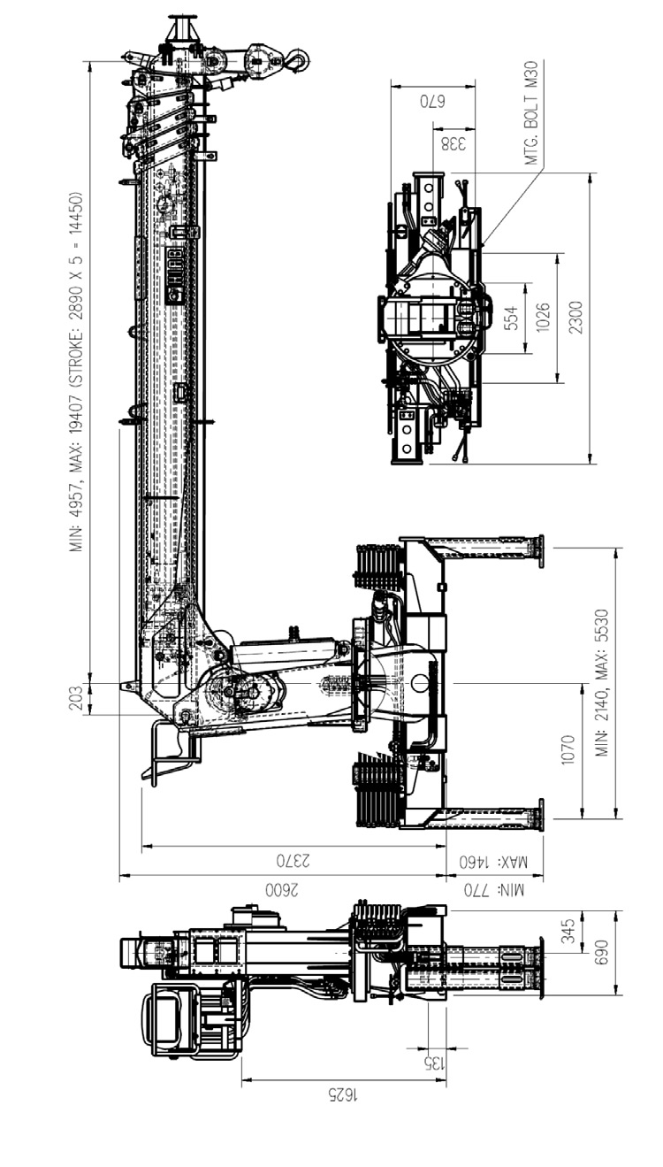
Кран манипулятор Hiab 190 Размеры
3 — 3 Таблица грузоподъемности и радиус действия КМУ Hiab 190
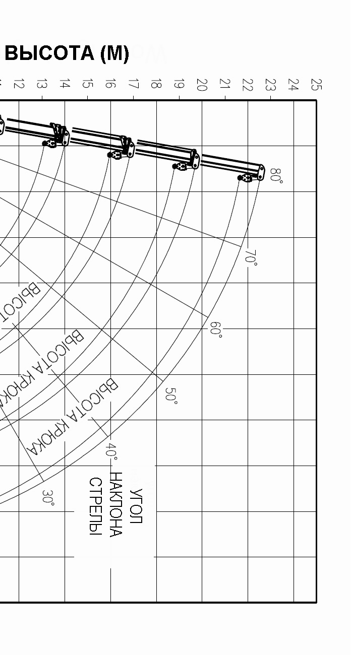
Таблица грузоподъемности и радиус действия КМУ Hiab 190
3 — 4 Гидравлическая схема КМУ Hiab 190

Гидравлическая схема КМУ Hiab 190
4. Общее описание КМУ
4 – 1 Основной принцип действия
Кран-манипулятор HIAB 190-Т состоит из стальных силовых конструкций и гидравлических компонентов.
Привод крана производится от гидронасоса через механизм отбора мощности шасси (РТО), который обеспечивает гидравлическую систему потоком масла высокого давления. Этот поток масла распределяется в цилиндры и гидромоторы с помощью гидрораспределителя и возвращается в маслобак.

Кран манипулятор Hiab 190 конструкция
4 – 2 Основные компоненты
1) Основание
2) Колонна
3) Стрела
4) Гидрораспределитель
5) Лебедка
6) Система опор
7) КОМ и насос
 Маслобак
9) Кресло оператора
1) Основание КМУ Hiab 190
Основание соединяется с конструкцией колонны с помощью поворотного подшипника, который обеспечивает вращение крана, и монтируется на раме шасси с помощью анкерных болтов.
2) Колонна КМУ Hiab 190
Колонна представляет собой закрытую сварную конструкцию, соединенную с основанием.
Колонна поддерживает стрелу с помощью гидроцилиндра. Лебедка монтируется в конструкции колонны.
3) Стрела КМУ Hiab 190
Стрела состоит из основной стрелы, двух выдвигающихся секций и цилиндров удлинителей.
Два цилиндра являются цилиндрами двойного действия. Разгружающий клапан позволяет цилиндрам работать с постоянной скоростью в
независимости от подвешенного груза.
4) Гидрораспределитель КМУ Hiab 190
Стреловой кран HIAB 190-T оснащен двумя 4-х секционными гидрораспределителями, соединенными последовательно. Один из них для
управления основными функциями крана (поворотом, подъемом стрелы, выдвижением, лебедкой), другой для управления опорами (балки опор и стойки опор). Оба гидрораспределителя оснащены встроенным главным перепускным и плунжерными перепускными клапанами, показанными на гидравлической схеме. Перепускные клапаны предохраняют кран от перегрузки при выполнении операций
5) Лебедка КМУ Hiab 190
Лебедка состоит из гидромотора, редуктора и барабана лебедки. Лебедка установлена внутри конструкции колонны. Гидравлический тормоз включен в редуктор лебедки.
6) Система опор КМУ Hiab 190
Система опор состоит из выдвижных балок и стоек, которые обеспечивают устойчивость крана во время его работы. Гидрозамок установленный на гидроцилиндр стойки, предотвращает самопроизвольное выдвижение штока стойки в транспортном положении и от падения крана при обрыве шланга стойки. Перед работой крана раздвиньте опоры и надежно установите их на землю для предотвращения опрокидывания крана, а так же для снижениия нагрузки на колеса и раму шасси.
7) Кресло оператора
4-х секционный гидрораспределитель, который управляет основными функциями крана (поворот, подъем стрелы, выдвижение телескопа, лебедка), смонтирован на кресле оператора. Так же там смонтирована педаль акселератора, которая помогает управлять частотой вращения двигателя шасси. Кресло имеет регулировку сиденья
КОМ и насос
Коробка отбора мощности (КОМ) монтируется на коробке передач шасси. Вращение от двигателя передается на насос для создания потока масла с большим давлением. КОМ разрабатывается под конкретное шасси, поэтому необходимо проконсультироваться с изготовителем шасси для подбора КОМ.
9) Маслобак
Кран HIAB-190T имеет маслобак для отдельного монтажа. Бак оснащен обратным фильтром, сеткой на заборном патрубке, сапуном, указателем уровня и сливной пробкой, которая используется для слива конденсата и отстоя.
4 –3 Система OLP (система защиты от перегрузки)
Полностью гидравлическая система защиты от перегрузки останавливает основной гидравлический поток, когда давление в гидроцилиндре стрелы достигает максимально допустимого уровня, предотвращая опасные движения. Система безопасности автоматически устанавливается в исходное положение после маневра, снижающего нагрузку, то есть, понижающего давление. Хотя система безопасности включается только с помощью давления гидроцилиндра цилиндра, она предотвращает все опасные движения. Только удлинитель может задвигаться вовнутрь в качестве исключения, чтобы решить проблему перегрузки. Кран и транспортное средство имеют гарантированную устойчивость.
5 . Эксплуатация КМУ
5 -1 Перед эксплуатацией крана
— Закрепите ручной тормоз шасси
— Проверьте уровень масла в гидробаке
— Запустите РТО (Коробку отбора мощности)
— Выдвиньте балки выдвижных опор и опустите выносные опоры на землю
5 — 2 Прогрев в холодную погоду
В холодную погоду вязкость рабочего масла может быть очень высокой, что может повредить гидравлические компоненты. Прогревайте следующим
образом:
— Запустите РТО и дайте поработать насосу на малых оборотах.
— Через 10-15 минут медленно приводите в движение кран, не допуская резких перемещений и крайних положений плунжеров
гидрораспределителя.
5 — 3 установка на опоры
Рычаги управления выносными опорами вертикально располагаются с обеих сторон крана. Их расположение (от кабины)
— 1-й – правая стойка
— 2-й – правая балка опоры
— 3-й – левая стойка
— 4-й – левая балка опоры
Выдвиньте балки опор. Устойчивость крана зависит от вылета балки опоры.
Надежно установите опоры на землю, не вывешивайте шасси.
Избегайте работы на склонах.
5 – 4 Эксплуатация крана
Стандартный гидрораспределитель имеет 4 рычага управления краном.
Смотрите нижеприведенную таблицу, в которой объясняется функция каждого рычага.

Управления краном манипулятором Hiab-190

Ррычаги управления краном Hiab-190
(Примечание)
1) Когда стрела поднимается/опускается, Медленно перемещайте рычаг, когда кран манипулятор нагружен.
Быстрые движения могут привести к опрокидыванию шасси или повреждению крана в результате динамических сил.
2) Когда крюк поднимается/опускается, Не опускайте ниже, когда груз коснется земли. Если Вы сделаете это, трос
может запутаться. При опускании груза минимум 3 витка троса должны оставаться на барабане. Для хорошей укладки троса наматывайте медленно.
3) При выдвижении благодаря селекторному клапану стрела выдвигается одна за другой, начиная с первой стрелы.
При втягивании — в обратной последовательности. Следите за перемещением крюка.
При выдвижении крюк поднимается, а при втягивании крюк опускается.
4) При повороте крана поворачивайте его как можно медленнее.
Когда Вы поворачиваете кран в сектор пониженной устойчивости, следите за устойчивостью шасси.
Никогда не поворачивайте кран до тех пор, пока груз не оторвется от земли.
5 – 4 Аварийная сигнализация КМУ Hiab 190
HIAB-190T оснащен системой оповещения о чрезмерном затягивании троса в стрелу. Если блок крюка находится слишком близко к головке стрелы крана, аварийная система активируется.
— Перед эксплуатацией крана включите систему аварийной сигнализации.
— Если система активирована, втяните стрелу или опустите крюк.
— После эксплуатации крана выключите переключатель системы аварийной сигнализации. Не укорачивайте длину троса.
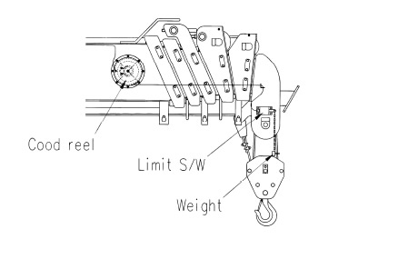
Аварийная сигнализация КМУ Hiab 190
Будьте осторожны при выдвижении стрелы или подъеме крюка, т.к. аварийная система не может включаться при повреждении электрического провода и т.д.
5 – 5 После эксплуатации крана манипулятора (для вождения)
— Полностью втяните стрелу
— Поверните стрелу в транспортное положение (передняя или задняя сторона). Смотрите метки на табличке поворотного устройства и основания колонны.
— Полностью втяните штоки опорных стоек
— Полностью втяните балки выносных опор.
— Опустите стрелу в самое нижнее положение.
— Зафиксируйте крюк с помощью предохранительного троса на шасси.
— Используйте (наматывайте) лебедку до тех под, пока предохранительный трос не натянется.
— Приведите рычаг ускорителя в нейтральное положение.
— Выключите коробку отбора мощности, затем насос перестанет работать. Вождение с работающим насосом может привести к повреждению РТО и насоса.
Очень опасно ездить с незакрепленным крюком.
Снова проверьте, что система выносных опор полностью втянута и зафиксирована.
Примечание.
Вождение с работающим насосом может привести к повреждению КОМ и насоса.
Очень опасно ездить с незакрепленным крюком.
Снова проверьте, что система выносных опор полностью
6. Инструкция по технике безопасности при эксплуатации КМУ Hiab 190
— Нажмите на педаль сцепления, а затем включите или выключите КОМ.
— В холодную погоду нагревайте рабочее масло в течение 10 – 15 минут.
— Эксплуатируйте кран на ровной поверхности земли.
— Перед использованием крюка включите аварийную систему, предотвращающую избыточную намотку троса.
— Будьте осторожны, не дотрагивайтесь до блока крюка на земле, что может привести к спутыванию троса.
— Нельзя тащить груз, используя кран, т.к. это может привести к повреждению крана.
— Не превышайте грузоподъемность крана, указанную на табличке грузоподъемности.
— Поворачивайте кран как можно медленнее.
— При погрузке и разгрузке под землей следите за оставшейся длиной троса на барабане лебедки. Должно оставаться минимум 3 витка.
— Не оставляйте кран в рабочем положении с подвешенным грузом.
— Не допускайте на рабочую площадку лиц, не имеющих на это разрешения.
— Убедитесь в том, что крюк надежно закреплен, а КОМ отключена перед началом движения транспортного средства.
— Если у Вас возникнут какие-либо проблемы, Вам необходимо проконсультироваться у Вашего дилера и/или квалифицированного
персонала.
— Плавно управляйте краном манипулятором.
Если Вы быстро управляете краном, срок службы крана может сократиться и/или могут возникнуть проблемы с комплектующими.
В начальной/конечной точке перемещения груза скорость движения должна быть уменьшена. Перед эксплуатацией крана убедитесь в том, что система выносных опор выдвинута и прочно установлена на земле. Если земля нетвердая, используйте опорную плиту под плиту балки выносных опор.
Примечания.
При низком числе оборотов двигателя в минуту стрела может вибрировать и/или не двигаться. В этом случае можно немного увеличить число оборотов двигателя в минуту.
Температура масла должна поддерживаться ниже 80°С. Высокая температура масла может привести к повреждению гидравлическим
компонентов. Температура от 45°С до 55°С считается самой лучшей рабочей температурой для крана.
7. Профилактическое техническое обслуживание и ремонт КМУ
7 — 1 Ежедневный осмотр

Техническое обслуживание и ремонт КМУ Hiab 190
7 — 2 Поворотный подшипник и крепежные болты
Если появляется какой-то отклоняющийся от нормы шум из поворотного устройства и/или крепежных деталей при работе крана или движении транспортного средства, пожалуйста, обратитесь к дилеру фирмы HIAB или в сервисный центр. Этот шум может возникать из-за плохо затянутых болтов. Крепежные болты поворотного подшипника КМУ, расположенного внутри колонны, должны проверяться по меньшей мере каждые два года.
7 – 3 Проволочный канат
1) Как устанавливать проволочный трос КМУ

Как устанавливать проволочный трос на КМУ Hiab-190
Пропустите конец проволочного каната в муфту троса в направлении стрелки, отмеченной на муфте.
Не забудьте закрепить клин и скобу для крепления троса. При прикреплении муфты троса к стреле убедитесь в том,
что знак стрелки на наружной поверхности муфты троса обращен к наружной стороне, как показано на рисунке.
2) Регулировка скрученного многожильного троса
Проволочный трос имеет тенденцию вращаться в направлении раскручивания при натяжении. Когда на крюке две или больше канатных петель, они могут легко вращаться, особенно, когда они еще новые. По мере использования проволочный трос вытягивается.
Процедура регулировки проволочного троса следующая:
— Полностью выдвиньте стрелу.
— Установите стрелу под углом приблизительно 65°.
— Поднимите груз настолько, чтобы натянулись проволочные тросы.
— Проверьте проволочные тросы на число оборотов.
— Удалите муфту троса и вращайте ее в направлении раскручивания
проволочного троса на число витков проволочного троса, умноженное на число канатных петель.
— После прикрепления муфты троса в исходное положение, наматывайте и разматывайте канатные тросы, повторяя это несколько раз, чтобы они вернулись в нормальное положение. Если все еще осталось перекручивание, повторите вышеупомянутую процедуру.
— Вращайте муфту троса в направлении, обратном направлению
раскручивания, за исключением 3-ей канатной петли, когда муфта троса должна вращаться в том же самом направлении.
3) Как следить за тросом лебедки
Трос лебедки необходимо регулярно чистить и смазывать для обеспечения максимального срока службы, помня, что трос подвержен износу и большим нагрузкам, которые устанавливают предел его срока службы. Хорошей практикой является замена троса на новый с регулярными интервалами. Постепенное изнашивание троса сложно обнаружить и измерить. Однако, можно выполнять следующие правила техники безопасности, применимые к тросам лебедок.
Трос лебедки должен быть заменен как только произойдет следующее:
— Когда 5 % любого отрезка троса, равного десяти диаметрам троса, нарушены, изношены или подвержены коррозии.
— Когда происходят заметные изменения диаметра (более 7 %) лебедки по сравнению с нормальным вытягиванием и сокращение диаметра
недавно установленного троса. На тросе образуются перегибы или сильные спиралеобразные скручивания.
4) Смазка троса лебедки
Когда трос используется в течение долгового времени он становится сухим, что приводит к быстрому износу и коррозионному разъеданию. Следовательно, необходимо смазывать трос с регулярными интервалами. Смазка должна выполняться следующим образом:
— Удалите пыль и грязь с троса и вытрите его насухо.
— Нанесите необходимое количество рекомендуемого смазочного вещества с помощью щетки, тряпки или подобного средства. Убедитесь в том, что используется только смазка для канатов.
7 – 4 Замена фильтрующего элемента
Чистая гидравлическая система обеспечивает лучшую экономию производственных затрат. Фильтрующий элемент масляного фильтра должен меняться в первый раз через 50 часов наработки, а затем каждые 500 часов наработки, но не менее двух раз в год.
Для достижения лучших результатов, всегда устанавливайте оригинальный фильтрующий элемент фирмы HIAB.
— Очистите фильтр перед удалением.
— Отвинтите крыльчатые гайки.
— Выньте фильтр.
— Отвинтите крыльчатые гайки.
— Удалите старый фильтрующий элемент.
— Очистите магнитный пруток.
— Установите новый фильтрующий элемент и новое уплотнительное кольцо.
7 – 5 Проверка при эксплуатации
— Отсутствие утечек масла
— Плавность работы крана
— Нет ли какого-либо отклоняющегося от нормы шума?
— Какая температура масла? Если температура масла выше 75 °С, остановите работу крана.
7 – 6 Проверка после эксплуатации
— Очистить, смазать
— Проверить отсутствие трещин и постороннего шума
— Проверить, нет ли утечки в соединениях
7 – 7 Проверка и техническое обслуживание КМУ Hiab 190 после первого месяца эксплуатации
— Проверьте установку давления и свинцовые пломбы
— Проверьте на утечку
— Проверьте и подтяните винтовые соединения.
— Проверьте и подтяните соединительные муфты шлангов и трубопроводов
— Проверьте фиксаторы и другие замковые устройства
— Проверьте функции и рычаги гидрораспределителя
— Проверьте крюк, канаты и другие используемые подъемные устройства
— Проверьте, чтобы все предупредительные таблички находились на своих местах
— Проведите визуальный осмотр несущих деталей с целью обнаружения деформации и трещин и т.д.
— Очистите или замените фильтры
— Проверьте уровень масла и смазки в соответствии с картой смазки в руководстве по эксплуатации
— Проведите испытание крана и испытание под нагрузкой, прислушиваясь к любым подозрительным шумам.
7 – 8 Контроль и техническое обслуживание КМУ Hiab 190 после 6 месяцев эксплуатации
— Очистите кран
— Проверьте установку давления и свинцовые пломбы
— Проверьте на утечку
— Проверьте и подтяните винтовые соединения.
— Проверьте и подтяните соединительные муфты шлангов и трубопроводов
— Проверьте фиксаторы и другие замковые устройства
— Проверьте функции и рычаги гидрораспределителя
— Проверьте крюк, канаты и другие используемые подъемные устройства
— Проверьте, чтобы все предупредительные таблички находились на своих местах
— Проведите визуальный осмотр несущих деталей с целью обнаружения деформации и трещин и т.д.
— Очистите или замените фильтры
— Проверьте уровень масла и смазки в соответствии с картой смазки в руководстве по эксплуатации
— Проведите испытание крана и испытание под нагрузкой, прислушиваясь к любым подозрительным шумам.
— Проверьте надежность крепления насоса и анкерных болтов
— Очистите или замените масло для гидравлических систем
8. Смазка
8 – 1 Замена масла в гидравлической системе
Проверяйте уровень масла в маслобаке каждый день. Уровень масла должен быть виден в смотровом стекле. При этой проверке кран должен находиться в парковочном положении. Долейте масло, если необходимо. Со временем масло для гидравлических систем загрязняется и
гидравлическая система может начать неправильно функционировать. Следовательно, необходимо менять масло для гидравлических систем не менее одного раза в год.
После замены масла необходимо прогнать все гидравлические функции крана в их полном диапазоне. Это необходимо делать для того, чтобы удалить какой-либо оставшийся воздух, который иначе может разрушить пломбы в гидравлической системе. Всегда помните, что Вы можете свести к минимуму проблемы, если будете содержать в чистоте гидравлическую систему. С этой целью всегда, когда Вам необходимо выполнять работы внутри гидравлической системы, поддерживайте чистоту и вокруг гидравлической системы.
При замене масла, в тоже время заменяйте и фильтры. Гидравлическая система и рабочая жидкость для гидравлических систем
должны соответствовать в отношении смазывающей способности, влияния на пломбы и другие материалы и невоспламеняемости. По этой причине не смешивайте разные типы жидкости для гидравлических систем, такие как минеральные масла, синтетические жидкости и жидкости на водной основе и никогда не подмешивайте в жидкость для гидравлических систем дизельное масло (топливо) или спиртосодержащие продукты.
Рекомендуемые масла (или их эквиваленты)
— Caltex Rando HD 32
— Shell Tellus 32
— Mobil DTE 24
8 – 2 Смазка
Хорошая и безотказная работа крана во многом зависит от обслуживания. Поэтому всегда выполняйте рекомендации по смазке в соответствии с картой смазки.

Смазка КМУ Hiab 190
9. Обнаружение неисправностей КМУ Hiab 190
Обнаружение неисправностей в основном базируется на общепринятой практике выявления определенного сбоя функционирования, его причине и способе устранения. В таблице, приведенной ниже, содержатся некоторые неисправности, которые могут возникать во время эксплуатации, причины их возникновения и способы их устранения. Однако, самым важным является то, что кран проверяется и необходимые регулировки выполняются до начала эксплуатации крана. Некоторые общие повреждения и неисправности.
— Кран используется не по назначению
— Кран и/или его вспомогательные устройства неправильно обслуживались
— Кран манипулятор эксплуатировался с перегрузкой

Обнаружение неисправностей КМУ Hiab 190

Обнаружение неисправностей КМУ Hiab 190
Предложите, как улучшить StudyLib
(Для жалоб на нарушения авторских прав, используйте
другую форму
)
Ваш е-мэйл
Заполните, если хотите получить ответ
Оцените наш проект
1
2
3
4
5
|
Краны-манипуляторы HIAB предназначены для самостоятельной погрузки и разгрузки транспортного средства, на котором они установлены, производства монтажных и строительных работ, бурения скважин, эвакуации автомобилей, инспекции мостов и т.д. Решающим фактором в использовании гидравлических кранов-манипуляторов стала экономическая целесообразность их применения на транспортных средствах. Автомобиль с манипулятором совмещает одновременно функции автокрана и грузовика.
Легкие краны — манипуляторы с оборудованием HIAB Заказать каталог запчастей на модель HIAB, ZEPRO, MOFFETT, MULTILIFT, LOGLIFT, JONSERED. Для заказа необходимо указать модель и год выпуска. При указании своего E-MAIL, обращайте внимание на точность его написания, т.к. если он будет указан не верно, мы не сможем с Вами связаться. Отправить заявку. Схемы установки гидроманипуляторов, гидравлические, электрические диаграммы, инструкции по обслуживанию и эксплуатации
Каталоги запчастей на краны манипуляторы HIAB HIAB T-Cranes HIAB K-Cranes HIAB 022-035 (Jet Grabber 5000) HIAB 060-112 HIAB 175-220 HIAB 225E-245E HIAB 360E-400E HIAB 190W/210W HIAB 055 XS-111 XS HIAB 122 XS-166 XS HIAB 244 XS-477 XS HIAB 600 XS-800 XS HIAB Rollers HIAB Sea crane Схемы гидравлических соединений, гидравлические диаграммы, гидравлика HIAB 022 Hydraulic diagrams HIAB T-cranes
HIAB K-cranes HIAB Rollers
HIAB Sea cranes Руководство по ремонту и обслуживанию кранов-манипуляторов HIAB 600-700-800 серии. Обслуживание гидравлических систем и контроль за этими системами. Монтаж крана-манипулятора на автомобиль: устойчивость, распределение нагрузки, присоединение крана к шасси автомобиля, расположение крепежа и усиление рамы, подбор гидравлического масла и его охлаждение, выполнение монтажа крана.
Каталоги запчастей на гидроборта-подъемники ZEPRO-HIAB ZEPRO LIFT MODEL 450kg: RZ45, RZC45, RZL45, RZLU45, RZN45, RZNU45, Z45, ZU45, ZL45, ZLU45, ZN45, ZNU45, RZU45, HZ45.
Каталоги запчастей, инструкция по установке, сервисная документация и сервисные бюллетени, схемы электрических соединений, гидравлические диаграммы, рабочие инструкции
Каталоги запчастей на серийные двигатели Kubota
Электрическая схема соединений на двигатель Kubota D1105/D1105-T (MOFFETT M4)
Каталоги запчастей, инструкция по эксплуатации MULTILIFT XR7, инструкции по установке MULTILIFT XR 2-5, MULTILIFT XR 7-8-10, MULTILIFT LHD MULTILIFT XR2/XR3/XR5/XR6 MULTILIFT XR7/XR8/XR10 MULTILIFT CLF (CLF 190/190-3W/260/260-3W/320/320-3W/380) MULTILIFT CCS MULTILIFT LHD (LHD A/LHD N/LHD P/LHS 251-261/LHZ 261) MULTILIFT XR21 (XR 21S61)
LOGLIFT выпускает манипуляторы для всех лесов мира. Модели подходят любым лесным машинам. Манипуляторы на лесных машинах могут достигать и весьма удаленных точек. Конструкция корпуса из высококачественной стали, позволяет использовать телескопические стрелы длинной более 10 м. Простые в эксплуатации, они являются очень эффективными при прореживании леса. Каталоги запчастей на гидроманипуляторы LOGLIFT Гидроманипуляторы для сортиментной заготовки Гидроманипуляторы для хлыстов Гидроманипуляторы для харвестеров Гидроманипуляторы для форвардеров Гидроманипуляторы для скиддеров Z-образные гидроманипуляторы Harvester cranes: L 120 V, L 130 V, L 141 V, L 170 V, L 181 V, L 200 V, L 220 V, L 280 V. Каталоги запчастей для дополнительного оборудования 102001 Hanger 45/35 80/80 L=200 77.5 102101 Rotator MR 10 F 102141 Rotator MR 8 AF 102122 Rotator GV 12-2 102161 Rotator GV 12 S 102231 Rotator GV 12 SA 102171 Rotator GV 14 S 102181 Rotator GV 14 SA 102112 Rotator GV 17 S 102191 Rotator GV 17 SA 102131 Rotator GV 104 S 102211 Rotator GV 124 102221 Rotator GV 124 S 102201 Rotaattori AV 12 S X Grapples: X40/42/43/53/55/56
Каталоги запчастей на гидроманипуляторы лесопогрузчики JONSERED Каталоги запчастей на дополнительное оборудование JONSERED Grapples: J560X/560XB/8110XB/860XB |
||


 Краны-манипуляторы HIAB. гидравлические автомобильные гидроманипуляторы HIAB:
 Грузоподъемность от 450 кг до 2500 кг.
 Kubota D722-EB
  Kubota D1105-EB
  Kubota D1105-T
  Kubota V2203-M-E2B
 Электрогидравлические платформенные подъемники MULTILIFT:
 Гидроманипуляторы для леса LOGLIFT:
 Гидроманипуляторы лесопогрузчики JONSERED: