
- Manuals
- Brands
- Terex Manuals
- Construction Equipment
- RT500-1
- Operator’s manual
-
Contents
-
Table of Contents
-
Troubleshooting
-
Bookmarks
Quick Links
Related Manuals for Terex RT500-1
Summary of Contents for Terex RT500-1
-
Page 3: Table Of Contents
Table of Contents Introduction …………………. 5 Construction and Industrial Equipment Product Safety ……5 Alert System………………..6 Nomenclature……………….. 7 Safety ………………….. 9 Safety Introduction………………9 General Safety………………10 Safety Sign Maintenance …………..10 Safety Sign Locations …………..11 Workplace Safety ………………19 Personal Safety ………………
-
Page 4
RT500 Contents Moving the Unit………………135 Vehicular Operation …………… 135 Traveling around the Jobsite …………138 Transportation ………………..139 Transporting the Crane …………….. 139 Maintenance………………..141 Lubrication Chart ……………… 141 Maintenance Introduction …………..142 Machine Maintenance Checklist …………143 Engine Maintenance…………….146 Engine Radiator Maintenance …………… -
Page 5
Hydraulic — General …………….204 Operator Controls …………….. 205 Axles…………………. 206 Steering Circuit ………………207 Alternator………………..211 Starter ………………..212 Brakes ………………..213 Parking Brake………………214 Air Pressure………………. 215 Swing Circuit ………………216 Boom Hoist Circuit…………….217 Boom Telescope Circuit……………. 218 Winch Circuit……………… -
Page 6
RT500 Contents Wire rope and reeving …………….278 Cable Sockets………………283 Applicable Standards / Regulations…………. 287 Wire Rope Users Manual …………..287 Appendix …………………. 347 Conversion Tables …………….347 Average Weight of Materials …………..351 Suggested Torque ratings…………..354 REVISED:… -
Page 7: Introduction
Terex manuals in the shipment of each product. It is company policy to provide this information for the owner or user of the equipment. It is…
-
Page 8: Alert System
RT500 Introduction Alert System The symbols below are used to inform the operator of important information concerning the operation of this unit. DANGER — Indicates an imminently hazardous situation which, if not avoided, will result in death or serious injury. WARNING — Indicates a potentially hazardous situation which, if not avoided, could result in death or serious injury.
-
Page 9: Nomenclature
Nomenclature This manual contains instructions and information on the operation, maintenance, lubrication and adjustments of the Rough Terrain Crane. The operator should not attempt to operate the machine before he has gained a thorough understanding of the material presented in the following pages. To aid in understanding the contents of this manual, the following terms will always have the meanings given whenever they are used.
-
Page 11: Safety
Many aspects of crane operation and testing are discussed in standards published by the American National Standards Institute. These Standards are updated on an annual basis with addendas, which are sent by ASME to the original purchasers of the standard. Terex recommends that you purchase and refer to the following standards.
-
Page 12: General Safety
RT500 Safety General Safety Safety Sign Maintenance Replace any missing or damaged safety signs. Keep operator safety in mind at all times. Use mild soap and water to clean safety signs. Do not use solvent-based cleaners because they may damage the safety sign material. The graphics on the following pages illustrate the location and give you examples of each safety decal located on your machine.
-
Page 13: Safety Sign Locations
Safety Sign Locations REVISED:…
-
Page 14
RT500 Safety REVISED:… -
Page 15
REVISED:… -
Page 16
RT500 Safety REVISED:… -
Page 17
REVISED:… -
Page 18
RT500 Safety REVISED:… -
Page 19
REVISED:… -
Page 20
RT500 Safety 18 — Inside Battery Box 19 — Inside Battery Box REVISED:… -
Page 21: Workplace Safety
Workplace Safety HANDLING PERSONNEL Cranes can only be used to lift people when it is the least hazardous way to do the job. (See OSHA 1926.550g, and ASME / ANSI B30.23.) TRAINING AND KNOWLEDGE Safety must always be the operator’s most important concern. Do not operate this crane until you have been trained in its operation.
-
Page 22
RT500 Safety OPERATOR’S RESPONSIBILITIES Be alert, physically fit and free from the influences of alcohol, drugs or medications that might affect the operator’s eyesight, hearing, or reactions. Keep people, equipment and material outside of the work area. 10. A signal person must be used when the operator’s vision is blocked or when working in hazardous areas such as near power lines or people. -
Page 23
RESPONSIBILITIES OF ALL CREW MEMBERS Unsafe conditions and/or practices must be corrected. Obey all warning signs. Watch out for your safety and the safety of others. Know and understand proper machine erection and rigging procedures. Alert operator and signal person of dangers, such as power lines, unstable ground, etc. MANAGEMENT RESPONSIBILITIES Operators must be competent, physically fit and, if required, licensed. -
Page 24
RT500 Safety PLANNING THE JOB 11. Determine the lift radius, boom angle and the rated lifting capacity of the crane. 12. Always pre-plan the course of each lift to determine the safest method to reach the load’s target destination. 13. Identify the location of gas lines, power lines, or other structures and determine if the crane or structures need to be moved. -
Page 25
OPERATOR AIDS CHECK Boom angle indicator. Travel Alarms. Anti-Two block devices. Overload prevention devices, load indicators and rated capacity limiters. OPERATION OVERLOAD PREVENTION Know the weight and characteristics of all loads to be lifted. Place the boom lifting point directly above the load when lifting. The load radius will increase when the load is lifted due to boom deflection.To compensate for the boom deflection, maintain the radius by raising the boom. -
Page 26
RT500 Safety POWER LINE SAFETY Determine whether there are power lines in the area before starting any job. Only operate around power lines in accordance with Federal, State and Local Regulations as well as ANSI B30.5 latest edition. Never remove materials from under powerlines with a crane if the boom or machine is capable of contacting them. -
Page 27
TRAVEL Watch for people, power lines, low or narrow clearance, bridge or road load limits, steep hills or uneven terrain. Place the boom in the stowed position. Inflate tires to specified pressure. Travel slowly and avoid sudden stops and starts. It is recommended that the seat belt be used during transit and travel. -
Page 28: Personal Safety
RT500 Safety Personal Safety SLIP AND FALL PREVENTION Always wait until machine has stopped before getting on and off equipment. Do not jump on or off. Do not use controls and steering wheel as hand holds. Keep the machine clean and dry. Remove all oil, grease, mud, ice and snow from walking surfaces.
-
Page 29: Assembly
Assembly Step Installation Steps (1) must be rotated into operation position. After delivery, remove the two capscrews (2) shown in the illustration and rotate the step down. Replace and tighten the capscrews. Do this on all four corners of the crane. Before loading the unit on a trailer, the steps must be returned to the upright position to provide sufficient ground clearance REVISED:…
-
Page 30: Spooling Wire Rope On Drums
RT500 Assembly Spooling Wire Rope on Drums Care must be exercised when installing wire rope on the winch drum. Improper spooling can. result in rope damage through crushing, kinking, dog- legs, abrasion and cutting. Poorly installed wire rope will also adversely affect the operating characteristics of the machine by causing uneven application of force and motion.
-
Page 31
Apply braking force to the reel flange in order to prevent overrun as the rope is being drawn off. Loops formed by overrun can cause kinks and doglegs in the rope, resulting in damage and premature rope failure. A timber or block forced against the shipping reel flange can be used to provide the required braking force. -
Page 32
RT500 Assembly adjacent turns are tight against one another. A lead or brass hammer may be used to tap the rope over against preceding turns. Tight winding on the drum is absolutely essential. Never use a steel hammer or pry bar to move the rope over on the drum. These tools can easily damage the rope. -
Page 33
Final seating of the wedge is accomplished by making lifts of gradually increasing loads. avoid imposing shock loads on the rope until the wedge is firmly in place. After the wedge has been firmly seated, a short length (6 inches) of the cable should be secured to the free end of the wire rope to act as a stop as shown. -
Page 34: Hoist-Line Reeving
RT500 Assembly Hoist-Line Reeving 1. AUXILIARY WINCH 2. MAIN WINCH 3. DEAD END FOR EVEN PARTS OF LINE 4. DEAD END FOR ODD PARTS OF LINE 5. IDLER SHEAVE 6. LOAD SHEAVE 7. BLOCK SHEAVE 8. 4 SHEAVE 9. WINCH DEAD END 10.
-
Page 35
SEEWire Rope Specifications on page 0 FOR CABLE SPECIFICATIONS AND Wire Rope and Reeving on page FOR CABLE AND SOCKET SPECIFICATIONS NOTE: SHEAVES IN BOOM HEAD AND HOOK BLOCK ARE NUMBERED FROM LEFT TO RIGHT AS VIEWED FROM THE OPERATOR’S STATION. “D” INDICATES PINNED END OF ROPE. -
Page 36
RT500 Assembly of line required for the load being lifted. Refer to the Crane Capacity Chart for parts of line required. REVISED:… -
Page 37: Cable Reeving
Cable Reeving CABLE REEVING When reeving the machine for any job, remember that hoisting and lowering speeds decrease as the number of parts of line increases. For the most efficient use of the machine, it is desirable to use the minimum number of required parts for lifting the anticipated loads.
-
Page 38: Side Stow Jib
RT500 Assembly Side Stow Jib DESCRIPTION Two optional jib extensions are available to provide additional boom reach. One is a 32ft (9.75 m) side stow swing-on one-piece lattice type jib that is offsettable at 0°, 15°, or 30°. The second jib option is a 33-57 ft. (10.05 — 17.37 m) side stow swing-on lattice type jib. The jib is extendible to 57 ft.
-
Page 39
ERECTING THE JIB Jib Storage Brackets Anti Two-Block Switch Jib Mounting Pins (4) Guide Rope Anti Two-Block Plug T-Handle Anit Two-Block Socket Extend and set the outriggers. Rotate the upper structure to the “over rear” position. Retract the boom completely. Boom down to minimum boom angle to allow ease of installation of the jib pins. -
Page 40
RT500 Assembly Booming down too quickly can result in damage to jib. 10. With the engine at idle, slowly boom down to minimum boom angle while another operator uses the guide rope to control the speed of the jib rotation. The jib will swing around until the left side mounting holes line up. -
Page 41
Boom down to minimum boom angle. Loosen the two (2) cap screws on the left side of the upper and lower sheave shafts. This will require a 3/ 4 inch hex wrench. Reeve the hoist line over the top center sheave on the boom head, around the jib sheave, and attach to the eye on the bottom of the jib tip. -
Page 42
RT500 Assembly EXTENDING AND RETRACTING THE JIB PULLOUT SECTION Pull Out Retaining Pin Hole Attach Dead End of Rope Pull Out Anti Two-block Plug Anti Two-block Extended Socket Two-Block Weight Anti Two-block Retracted Socket REVISED:… -
Page 43: Description Of Machine And Controls
Description Of Machine and Controls Universal Symbol Identification WINDSHIELD WASHER OIL PRESSURE HEATER TEMP WINDSHIELD WIPER HEAT VARIATION HEADLIGHTS WATER TEMPERATURE LOW COOLANT FUEL LEVEL ENGINE BRAKE KEY ON BATTERY VOLTAGE LOW AIR PRESSURE DIFF LOCK REVISED:…
-
Page 44
RT500 Description Of Machine and Controls ABS DIAGNOSTIC PTO ENGAGED PARKING BRAKE ABS EVENT AIR SUSPEN. FILL KEY — ACC DIAGNOSTIC AIR SUSPEN. DUMP KEY — OFF INCR / IDLE ADJ INCREASE HIGH SPEED REAR AXLE KEY — ON INCR / IDLE ADJ DECREASE REVISED:… -
Page 45
LOW SPEED REAR AXLE KEY — START ENGINE STOP DIFF LOCK ON PTO IN DIFF LOCK OFF PTO OUT IGNITION ENGINE WARN REVISED:… -
Page 46: Upper Controls And Instruments
RT500 Description Of Machine and Controls Upper Controls and Instruments 7. VOLTMETER 44. ENGINE STOP BUTTON 15. TURN SIGNAL / WIPER LEVER 45. FIRE EXTINQUISHER 17. TACHOMETER 46. LOAD MOMENT SYSTEM (LMI) 22. BUBBLE LEVEL 47. DEFROSTER FAN 34. GEAR SELECTOR 48.
-
Page 47
1. FUEL GAUGE 10. WORKLIGHT SWITCH 2. SWING LOCKED INDICATOR 11. SWING BRAKE RELEASE 3. ENGINE COOLANT TEMPERATURE GAUGE 12. DEFROSTER FAN SWITCH 13. OUTRIGGER EXTEND/RETRACT 4. REAR AXLE CENTERED INDICATOR MASTER 5. ENGINE OIL PRESSURE GAUGE 14. SWING LOCK SWITCH 8. -
Page 48
RT500 Description Of Machine and Controls 18. TRANSMISSION TEMPERATURE 28. ENGINE STOP / FAULT 19. TURN SIGNAL INDICATOR 29. IGNITION SWITCH 20. TRANSMISSION OIL PRESSURE 30. LEFT FRONT OUTRIGGER SWITCH 21. LOW AIR PRESSURE 31. RIGHT FRONT OUTRIGGER SWITCH 23. AIR PRESSURE GAUGE 32. -
Page 49
40. SWING BRAKE 42. ACCELERATOR 41. BOOM EXTEND/RETRACT PEDAL 43. BRAKE PEDAL REVISED:… -
Page 50
RT500 Description Of Machine and Controls 55. SWING/AUX WINCH CONTROL — Move joystick forward to pay out aux winch rope. Move joystick backward to take in aux winch rope. Move joystick left to swing boom left. Move joystick right to swing 57. -
Page 51
59. BOOM HOIST/MAIN WINCH CONTROL — Move joystick forward to pay out main winch rope. Move joystick backward to take in main winch rope. Move joystick left to 56. WINCH DISABLE SWITCH-Press switch raise boom. Move joystick right to lower to disable winch. -
Page 52
RT500 Description Of Machine and Controls 1. FUEL GAUGE — Graduated in quarters of 9. DASH LIGHT SWITCH — Push left for dash full tank. lights only, push right for dash lights and head lights. 2. SWING LOCKED INDICATOR — Indicates 10. -
Page 53
5. ENGINE OIL PRESSURE GAUGE — 13. OUTRIGGER EXTEND/RETRACT Measures engine oil pressure. MASTER SWITCH — This switch is used in conduction with outrigger switches (19) to extend and retract the outrigger beams and jacks. Push left to retract and right to extend. 6. -
Page 54
RT500 Description Of Machine and Controls 18. TRANSMISSION TEMPERATURE 29. IGNITION SWITCH GAUGE 19. RIGHT TURN SIGNAL 30. JACK SWITCH (LEFT FRONT) — Used in conjuction with switch (13), to extend and retract outrigger jack and beam. 20. TRANSMISSION OIL PRESSURE 31. -
Page 55
23. AIR PRESSURE GAUGE — 105 — 125 psi 33. JACK SWITCH (RIGHT REAR) — Used in optimum operating pressure. conjuction with switch (13), to extend and retract outrigger jack and beam. 24. PARK BRAKE INDICATOR 34. GEAR SELECTOR 25. LOW WATER INDICATOR 35. -
Page 56
RT500 Description Of Machine and Controls 40.SWING BRAKE — Apply to prohibit boom 42.ACCELERATOR — Push to increase from swinging engine RPM and release to decrease. 41.BOOM EXTEND RETRACT PEDAL — Tilt 43.BRAKE PEDAL — Push to stop carrier the pedal halfway forward to power-extend movement. -
Page 57
17. TACHOMETER 46. LOAD MOMENT INDICATOR-Read Terex RCI 510 Operator’s Manual to fully understand functional operation and safety of this unit. 22. BUBBLE LEVEL-Indicates crane level 47. DEFROSTER FAN condition. -
Page 58
RT500 Description Of Machine and Controls 37. SWING BEARING GREASE FITTING- 50. HEATER ON/OFF SWITCH Attach grease gun and swing machine slowly while applying grease. 38.HAND THROTTLE — Holds engine throttle 51. HEATER FAN CONTROL at an operator settable position. Place the accelerator (42) at approximate RPM. -
Page 59: Inspection
Inspection Pre-Start Inspection Inspection Check List This check list is to be used in addition to the information provided in this manual to properly operate and maintain the machine. Table 1: ITEMS TO BE INSPECTION SATISFACTORY ADJUST REPAIR INSPECTED & CODE CHECKED VISUAL INSPECTION…
-
Page 60
RT500 Inspection ITEMS TO BE INSPECTION SATISFACTORY ADJUST REPAIR INSPECTED & CODE CHECKED MUFFLER/EXHAUST SYSTEM ALL CONTROL MECHANISMS INSTRUMENT GAUGES CLUTCHES & BRAKES D WIRE ROPE, SHEAVES & GUARDS TWO BLOCK DAMAGE PREVENTION SYSTEM LOAD SUPPORTING COMPONENTS CONDITION FIRE EXTINGUISHER BACKUP ALARM BOOM ANGLE INDICATOR… -
Page 61
ITEMS TO BE INSPECTION SATISFACTORY ADJUST REPAIR INSPECTED & CODE CHECKED AIR CLEANER ELEMENT CLUTCH & BRAKE LINKAGE & PINS WHEEL LUG NUT TORQUE FAN BELT TENSION STRUCTURAL MEMBERS & WELDS BOOM INSPECTION BATTERIES & STARTING SYSTEM ALCOHOL EVAPORATOR CHROMED CYLINDER RODS SWING BEARING BOLT TORQUE… -
Page 62
RT500 Inspection FUEL Engine fuel and propane/diesel for the upper unit heater should be adequate for sustained operations. LUBRICATION Perform the daily lubrication as required in the Lubrication Recommendations. HYDRAULIC SYSTEM Check hoses, tubes, components, reservoir sight gauge, valves, pumps, motors, connections, reservoir oil temperature, cylinder mounting bushings and pins. LINES AND BLOCKS Inspect the hoist lines, hoist block, hook latch, and ball hook, as well as the crane attachment in general for readiness. -
Page 63: Wire Rope Inspection Record
Wire Rope Inspection Record REVISED:…
-
Page 64: Crane Boom
RT500 Inspection Crane Boom WEEKLY: STRUCTURAL MEMBERS AND WELDS Visually inspect all structural members and welds including (but not limited to) the extended boom for straightness, roller (or pad) adjustment, and cracks. Pay special attention to the longitudinal welds joining the top, side and bottom plates.
-
Page 65
If any indicator decals are missing or illegible (either triangle markers or boom length numbers), order the applicable items through your distributor and apply them using the dimensions given on the following page. REVISED:… -
Page 67: Operating Instructions
Operating Instructions General Operational Issues Operator Shutoff Devices ANTI-TWO BLOCK SYSTEM Inspect all anti-two block switches found on the boom, jib and auxiliary sheave heads for damage. Check the freedom of the counterweight attached to these switches; and also, that the counterweight is attached around correct line of hoisting cable in the proper manner.
-
Page 68
RT500 Operating Instructions REVISED:… -
Page 69
• Installation/Operator Manuals The MicroGuard® TEREX RCI 510 System is intended to aid the crane operator by continuously monitoring the load and warning of an approach to an overload or Two-Block condition. Crane functions are monitored by means of high accuracy sensors. The system continuously compares the load suspended below the boom head with the crane capacity chart stored in the computer memory. -
Page 70
RT500 Operating Instructions EXTENSION SENSOR The extension sensor provides an increasing voltage proportional to the extension of the boom. A cable attached to the boom head provides a low current electrical path for the A2B signal PRESSURE TRANSDUCERS Two pressure transducers measure the pressure in the boom hoist cylinder. The resultant Total Moment signal is processed to provide a continuous display of the load suspended below the point of lift. -
Page 71
THE PICTOGRAPH The PICTOGRAPH gives a pictorial representation of the current setup of the system. It does this by means of light emitting diodes (LEDs). Each shaded area contains a group of one or more LEDs and a push button that is pressed to change the setup selection. In the groups with more than one choice or option, LED’s illuminate one at a time to indicate the selection. -
Page 72
RT500 Operating Instructions OUTRIGGERS — contain 3 LEDs. These MANUAL SECTION — contains 1 LED. It is indicate the selection of either full outriggers, active on cranes that have pinned intermediate, or retracted outriggers. extensions or active tip boom options. TIRES — contain 1 LED. -
Page 73
WHAT DOES IT TELL YOU? REVISED:… -
Page 74
RT500 Operating Instructions 1. The INFORMATION SCREEN contains 4. The PRE-ALARM (AMBER) indicator details of the currently selected configuration. illuminates at a preset value of 90% of Rated Capacity and provides a visual indication of approach to overload. 2. PARTS-OF-LINE displays the parts of line 5. -
Page 75
7. The BAR GRAPH indicates the ACTUAL 10. The RADIUS display shows radius of the LOAD as a PERCENTAGE OF RATED load. Radius is the horizontal distance from CAPACITY. the centerline of rotation to the centerline of the lifting point. 8. -
Page 76
RT500 Operating Instructions WHAT MUST YOU TELL IT? REVISED:… -
Page 77
13. The number of PARTS-OF-LINE 18. JIB STOWED ON BOOM 14. POINT OF LIFT, e.g. main boom, 19. Indicates which WINCH will be used for auxiliary head or jib. the pick. 15. AUXILIARY HEAD ON or OFF the crane. 20. Indicates which COUNTERWEIGHT is fitted (if applicable). -
Page 78
RT500 Operating Instructions Immediately following electrical power up or following operation of the TEST switch (item 26), the system executes a self-test that last for 8 seconds. During this time, the numerical display segments and bar graph segments are all turned on, the audible alarm will sound, and alarm indicator lights are illuminated. -
Page 79
BRIGHTNESS AND CONTRAST CONTROLS Immediately following self-test and the start up screen, the information display will display a 2 second reminder of the brightness and contrast control functions. Push buttons to the left of the information display (item 25) allow the brightness of all LED’s on the display panel to be adjusted up or down at any time during operation of the system unless operator alarms are being set. -
Page 80
RT500 Operating Instructions During adjustment of the contrast or brightness, the information window will automatically display the reminder window shown. SYSTEM SETUP COUNTERWEIGHT IF THE COUNTERWEIGHT PUSH BUTTON IS PRESSED ON A CRANE THAT DOES NOT HAVE COUNTERWEIGHT OPTIONS, THE MESSAGE “NO OTHER COUNTERWEIGHT OPTIONS”… -
Page 81
• On cranes that have counterweight options the operator must tell the MicroGuard® System which counterweight is currently fitted. If there are no options, continue on to selection of outriggers. • Start the choice by pressing the counterweight push button (item 20). •… -
Page 82
RT500 Operating Instructions OUTRIGGERS • The operator must tell the system which outrigger position is in use. • Start the choice by pressing the outrigger push button (item 22). • The outrigger selection will automatically move on to the next selection. EXAMPLE: From fully extended to half extended, or from half-extended to fully retracted and then back to fully extended with each push of the button. -
Page 83
TIRES/RIGGING TRAVEL IF THE TIRE PUSH BUTTON IS PRESSED ON A CRANE THAT DOES NOT HAVE TIRE OPTIONS THE MESSAGE “NO OTHER TIRE OPTIONS” WILL APPEAR IN THE INFORMATION DISPLAY. REFER TO YOUR CRANE RATING MANUAL FOR DETAILS OF THE OPTIONS ON YOUR CRANE. •… -
Page 84
RT500 Operating Instructions STOWED JIBS IF THE STOWED JIB PUSH BUTTON IS PRESSED ON A CRANE THAT DOES NOT HAVE JIB OPTIONS, THE MESSAGE “NO OTHER STOWED OPTIONS” WILL APPEAR IN THE INFORMATION DISPLAY. REFER TO YOUR CRANE RATING MANUAL FOR DETAILS OF THE OPTIONS ON YOUR CRANE. -
Page 85
If the required option is visible, select the option by pressing the button next to it. If more than 4 options are available, a second selection screen can be viewed by pressing the button next to the «next» label. If only a single option is available, it will automatically be selected. ERECTED JIBS IF THE ERECTED JIB PUSH BUTTON IS PRESSED ON A CRANE THAT DOES NOT HAVE JIB OPTIONS, THE MESSAGE “NO OTHER JIB OPTIONS”… -
Page 86
RT500 Operating Instructions • To erect a JIB, it must first have been selected and stowed as detailed on the previous page. • Start the choice by pressing the erected jib push button (item 16). • The available erected jib options will be displayed in the information screen (item 1). There can be four options displayed at a time, one next to each selection key. -
Page 87
AUXILIARY HEAD IF THE AUXILIARY HEAD PUSH BUTTON IS PRESSED ON A CRANE THAT DOES NOT HAVE AN AUXILIARY HEAD, THE MESSAGE “NO OTHER AUXILIARY HEAD OPTIONS” WILL APPEAR IN THE INFORMATION SCREEN (ITEM 1). An auxiliary head fitted on a crane must be included in the crane setup. To set up the crane with an auxiliary head, press the auxiliary head push button, (item 15). -
Page 88
RT500 Operating Instructions CHOOSING THE WINCH For cranes with two winches, always select the winch to be used for the lift before selecting the point of lift and parts of line. The system stores point of lift and parts of line selections for each winch. -
Page 89
CHOOSING THE POINT OF LIFT Before choosing the point of lift, check that the correct winch has been selected. Always check the point of lift selection following selection of the winch. • Choose the point of lift to be either from the main boom, auxiliary head, or jib by pressing the point of lift push button (item 14). -
Page 90
RT500 Operating Instructions SETTING THE PARTS-OF-LINE Always check and select parts-of-line following selection of the winch and point of lift. • Set the PARTS-OF-LINE for the currently selected winch by pressing the UP or DOWN arrow, as appropriate. (item 13). •… -
Page 91
The system has the capability of remembering all of the configuration data previously set. After removing power to the system and then powering up again, the settings remain intact until reset by the operator. • After the configuration has been set, the operation of the System depends only upon setting which winch is in use. -
Page 92
RT500 Operating Instructions PUSH BUTTON TO CANCEL AUDIBLE ALARM The cancel alarm push button (item 23) is used to silence the audible alarm. Pressing this button once will cancel an audible alarm that has occurred as a result of an: Overload A2B Alarm Operator Settable Alarm… -
Page 93
The CANCEL ALARM push button is also used to reset the function kick-out relay when it is necessary to bypass the function disconnects. Examples of when it may be necessary to override a function disconnect condition are: • If the boom hoist cylinder is fully extended, the pressure in it will rise. This will be seen by the system as an overload and will not allow the operator to boom down. -
Page 94
RT500 Operating Instructions beep is heard confirming the bypass. When the condition that caused the alarm is no longer present, the function disconnect relay will reset to the normal condition. Should a different alarm condition occur while the relay is overridden, the new alarm condition will cause the controls to disconnect again. -
Page 95
ACCESSING THE OPERATOR ALARMS To access the Operator Alarms from the main working screen, press the operator alarms push button (item 24). The Information Screen will then show the current status of the alarms. The four operator alarms are shown below followed by the number identity of the push button that controls each alarm. -
Page 96
RT500 Operating Instructions SETTING MINIMUM BOOM ANGLE ALARM • Move the boom to the desired minimum angle (in this example 32°). • Press the operator alarm push button (item 24) to access the operator alarm screen. • Press the push button (item 28) pointing to Min Angle. In this example the display will read MIN ANGLE 32°. -
Page 97
SETTING MAXIMUM BOOM ANGLE ALARM • Move the boom to the desired maximum angle (in this example 67°). • Press the operator alarm push button (item 24) to access the operator alarm screen. • Press the push button (item 29) pointing to Max Angle. In this example the display will read MAX ANGLE 67°. -
Page 98
RT500 Operating Instructions SETTING MAXIMUM BOOM LENGTH ALARM • Move the boom to the desired maximum length, in this example 58 ft. • Press the operator alarm push button (item 24) to access the operator alarm screen. • Press the push button (item 25) pointing to Max Length. In this example the display will read MAX LENGTH 58 FT. -
Page 99
ACCESSING SWING AND WORK AREA ALARMS To access the SWING AND WORK AREA ALARMS from the main working screen, press the OPERATOR ALARM push button (item 24) 2 times. The Information Screen will show the current status of the Swing and Work Area Alarms. There are 4 separate operator alarms, all controlled by push buttons (items 25, 27, 28, and 29). -
Page 100
RT500 Operating Instructions When Operator Alarms are set, the light in the push button (item 24) will be illuminated. Return to the main screen by pressing the OPERATOR ALARM push button (24). SWING ALARMS These alarms, when set, permit the operator to define a Working Arc and an Exclusion Zone by two set points. -
Page 101
A left swing alarm is activated when swinging to the left. A right swing alarm is activated when swinging to the right In this example, the working arc is the larger piece of the pie. REVISED:… -
Page 102
RT500 Operating Instructions THE OPERATOR DEFINED SWING ALARM IS A WARNING DEVICE. ALL FUNCTIONS REMAIN OPERATIONAL WHEN ENTERING THE OPERATOR DEFINED EXCLUSION ZONE. IT IS THE RESPONSIBILITY OF THE OPERATOR TO SET SWING ALARMS THAT ENSURE THAT THE CRANES BOOM, ATTACHMENT, LOAD, AND RIGGING ETC. -
Page 103
SETTING LEFT SWING ALARM • Swing the boom to the desired Left Swing Limit, e.g. 325°. Press the operator alarm push button (item 24) 2 times to access the swing alarm screen. • Press the push button (item 28) pointing to Left Swing. The information screen (item 1) will read LEFT SWING 325°. -
Page 104
RT500 Operating Instructions The operator defined work area alarm, when set, will define an imaginary vertical plane between two set points to optimize the working area. When passing the plane, the red warning lamp will illuminate, the audio alarm will sound, and the message “EXCLUSION ZONE”… -
Page 105
THE OPERATOR DEFINED WORK AREA ALARM IS A WARNING DEVICE. ALL FUNCTIONS REMAIN OPERATIONAL WHEN ENTERING THE OPERATOR DEFINED EXCLUSION ZONE. “SAFE WORKING DISTANCE” IS THE TIME IT WOULD TAKE AN OPERATOR TO REACT TO AN ALARM AND FOR THE CRANE MOTION TO BE HALTED BEFORE ENTERING THE EXCLUSION ZONE. -
Page 106
RT500 Operating Instructions WORK AREA SELECTION MODE • Press the operator alarm push button (item 24) two times to access the Work Area alarm screen. SETTING POINTS 1 AND 2 • Move the boom, attachment, load, rigging etc. to the desired LEFT SET POINT. •… -
Page 107
• Move the boom, attachment, load, rigging etc. to the desired RIGHT SET POINT. • Press the push button (27) pointing to Right Point. The information screen (item 1) will read RIGHT POINT SET. The red warning light (item 5) will flash and the audible alarm will sound whenever the boom tip penetrates the exclusion zone. -
Page 108
RT500 Operating Instructions FUNCTION KICK-OUT A device that disengages certain crane functions whose movement could cau HEIGHT The vertical distance from the ground to the tip of the boom or attachment. HORIZONTAL Parallel to the horizon. INFORMATION SCREEN A display that gives information supplemental to the information on the picto INTEGRATED CIRCUITS A tiny complex of electronic components and connections on a small slice of Something attached such as a lattice fly or jib on a crane boom. -
Page 109
TWO-BLOCKING The condition when the lower load block or hook assembly comes in con UNLADEN A boom that has no additional stowed or erected attachments and that is WINCH A hoist drum used in conjunction with a rope for raising and lowering load WORK AREA ALARM Permits the operator to define an operating zone by the means of only tw CALIFORNA — PROPOSITION 65 WARNING… -
Page 110: Operating The Unit
RT500 Operating Instructions Operating the Unit Starting the Engine Once the pre-start inspection ( pg. 65 & 66) has been completed, the engine may be started. At ambient temperatures over 32 deg. F. on Cummins Engines, follow the starting procedure below: STARTING PROCEDURE Open the throttle to the idle position.
-
Page 111: Cold Weather Starting
Cold Weather Starting At very low temperatures, when the engine is difficult to start and operator experience so indicates, follow the starting procedure outlined below: Cold Weather Procedure Disengage the pumps. Wait for “Wait to Start” light to go off. Start the engine as described above.
-
Page 112: Jump-Starting An Engine With Booster Cables
The ground lead is connected to the engine block, frame, or some other good metallic ground. The battery terminal connected to the starter relay is the one which is not grounded. Terex Cranes are always shipped with the negative (-) as ground.
-
Page 113: Operating The Engine
Operating the Engine If the engine oil pressure gauge does not register normal operating pressure within 30 seconds of starting, shut down the engine, determine the cause and effect repairs before re- starting the engine. When the engine reaches operating temperature, operations may begin. While the engine is running, check the gauges at frequent intervals and be alert for any abnormal engine sounds or faulty engine performance.
-
Page 114: Making A Typical Lift
RT500 Operating Instructions Making a Typical Lift Making a Typical Lift In making lifts, the operator must successfully coordinate several crane functions. These include the boom raise/lower, boom extend/retract, load hoist/lower and swing functions. Although experienced operators tend to operate two or more of these functions simultaneously, the lift procedure can be broken down into the following sequence of operations.
-
Page 115
The operator must exercise sound judgment in positioning the outriggers. The outriggers should not be set near holes, on rocky ground or on extremely soft ground. Setting the outriggers in such locations may result in the crane tipping, causing personal injury or property damage. Where a firm footing or level ground is not otherwise available, it should be provided by substantial timbers, solid blocking, or other structural members sufficient to distribute the load so as not to exceed the safe… -
Page 116
RT500 Operating Instructions capacity chart for all given loads. Reeving with more parts of line than required may result in all of the wire rope being payed off the winch drum. The intent of this caution is to prevent any possibility of either reverse winding of the rope on the winch drum, which could cause breakage of the winch rope, or of unseating the rope wedge in the winch drum, which could result in the uncontrolled fall of the hook block and load. -
Page 117
GRADUALLY slow the swing by use of the joystick. First, move the joystick to the neutral position and then VERY SLOWLY into the opposite swing direction position as required to slow the swing. Apply the swing brake, with the foot pedal, when the swing is stopped or when emergency situations dictate that the swing be terminated abruptly. -
Page 118
RT500 Operating Instructions release this lever slowly to minimize dynamic effects of the load and to prevent “birds-nesting” of the cable on the winch drum. To shift the winch into the high-speed mode the winch switch on the front of the joystick must be pressed. -
Page 119
exceeding the rated load as determined by the load rating charts. When operating a hydraulic crane, the operator should realize that hydraulic and structural competence, NOT TIPPING LOAD, is often the determinant of lifting capacity. Therefore, THE OPERATOR MUST BE GUIDED SOLELY BY THE APPROPRIATE MANUFACTURER’S LOAD RATING CHART when considering load weight. -
Page 120: Arm And Hand Signals
RT500 Operating Instructions Arm and Hand Signals HOIST. With LOWER. With USE MAIN USE WHIPLINE. RAISE BOOM. forearm vertical arm extended HOIST. Tap fist (Auxiliary Hoist) Arm extended, fore finger downward on head; then Tap elbow with fingers closed, pointing up, forefinger use regular one hand, then…
-
Page 121
STOP. Arm EMERGENCY TRAVEL. Arm TRAVEL.(Both extended, palm STOP. Both extended EVERYTHING. Tracks.) Use down, move arm arms extended, forward, hand Clasp hands in both fists in front back and forth palms down, open and slightly front of body. of body, making move arms back raised, make a circular motion… -
Page 122: Load Rating Chart Interpretation
RT500 Operating Instructions Load Rating Chart Interpretation In the following pages are examples of a load chart, these example charts may differ from the chart supplied with your crane. Always use the load rating chart supplied with the crane to interpret the conditions and limitations that exist when making a lift with the crane. The determining factors are lifted load, radius, boom angle, working position, hoist line reeving, tire pressure, travel data, use of a jib, and any other special conditions that exist, such as wind velocity, soil conditions, etc.
-
Page 123
should be removed. In certain instances, it is advantageous, from a job set-up point of view, to lift over the boom point with the jib erected. In these instances, it is necessary to make deductions from the rated loads shown in the load rating chart “Jib Erected But Not Used“… -
Page 124
RT500 Operating Instructions On Outriggers Load Ratings: To determine the boom extension capacities with the crane on outriggers, use the following procedure: Determine weight of load to be lifted. Determine weight of slings and rigging hardware. Determine weight of hook block. Determine other capacity deductions. -
Page 125
Determine load radius, boom angle, and boom length. Compare load weight with chart rated capacity for the boom length, radius, and boom angle. The lifted load must not exceed the chart rated capacity for the boom length and radius. In this example, the lifted load of 25,300 lbs. is less than the rated load of 27,800 lbs. and can be handled as long as the machine is on outriggers per Notes 6 &… -
Page 126
RT500 Operating Instructions SIDE-STOW JIB Jibs are rated by boom angle only and not by radius. This means that as long as the boom is at 61° boom angle and the jib at 30° offset, before loading, no matter if the boom is fully extended or retracted, it can only lift a maximum of 3,300 lbs. on a 33 foot side-stow jib. -
Page 127
Determine capacity deductions. Calculate weight of lifted load. Determine jib type and length, jib offset, main boom angle. Select correct jib load chart (stowaway or sidestow). Compare load weight with chart rated capacity for the jib length, boom angle, and jib offset (if applicable). In the following example the crane is set up as follows: On outriggers. -
Page 128
RT500 Operating Instructions ON TIRES On tires operation, particularly pick and carry, must be done in a slow, smooth manner over level terrain that will support the crane, with the loads close to the ground and the boom as low as possible to avoid the load swinging unintentionally, causing injury or tip over. -
Page 129
“Stationary” means that the crane cannot be moved when loaded to the levels shown in the on tire load chart. Ensure that the tires are inflated as shown in the recommended tire pressure chart on pg. 113. “Creep” means the crane can be moved at a maximum speed of one (1) MPH for a distance of 200 feet and then a 30 minute waiting period is necessary to cool the tires. -
Page 130
RT500 Operating Instructions STABILITY/ STRUCTURAL STRENGTH Crane load ratings with an asterisk (*) beside them are based on the machine’s structural strength. All other ratings are based on stability. Therefore, when lifting in an area where the rated load is governed by strength, an overload can produce an abrupt failure. This may be in the boom, outrigger beam, or elsewhere. -
Page 131: On-Tires» Lift
«On-Tires» Lift Listed below are special precautions for “On Tires” lifts. «On-Tires» Lift Procedure The boom shall be carried straight over the front of the crane. Travel speed reduced to suit conditions. Maintain specified tire pressures. Avoid sudden starts and stops. Provide tag or restraint lines to snub swinging of the load.
-
Page 132
RT500 Operating Instructions Death or Serious Injury can result from an overturning crane. The boom angle must be below 53 degrees unless the boom is positioned in-line with the cranes chassis or is positioned on outriggers. On retracted outriggers, the boom angle must be below 65 degrees unless the boom is positioned in-line with the crane chassis. -
Page 133: Unusual Operating Conditions
Unusual Operating Conditions Special problems in maintenance and operation are caused by unusual conditions such as extremes in heat, cold and humidity, high altitude, salt water, and dusty or sandy work sites. When operating under such conditions, special precautions must be taken to prevent damage, minimize wear, and avoid component deterioration.
-
Page 134
RT500 Operating Instructions The battery can discharge if snow or ice short circuits the terminals. Keep the battery posts and cable connectors clean and dry. Remove any corrosion with a solution of soda and water. During extremely cold weather, it is advisable to remove and store the battery in a heated area when the crane is to remain idle overnight or for any extended period. -
Page 135
Engine overheating due to loss of coolant will most often be corrected by SLOWLY adding coolant while the engine is running at FAST IDLE. Should this fail to correct the problem, drain and flush the system and refill with fresh coolant (50% solution of ethylene glycol) and a corrosion inhibitor. -
Page 136
RT500 Operating Instructions it takes for lubricants, breathers and filters to accumulate unacceptable amounts of sand or dust. The frequency of lubrication and service should be adjusted accordingly. HIGH HUMIDITY OR SALTWATER In some locations, such as coastal areas, the crane may be exposed to the deteriorating effects of salt, moisture, or both. -
Page 137: Moving The Unit
Moving the Unit Vehicular Operation The Rough Terrain Crane is capable of both off road and limited on-road travel. The kind of travel undertaken will determine how the carrier is operated. Before moving the Before moving the crane, either around the work site or between sites, carefully consider the terrain type, road conditions and any hazards likely to be encountered enroute.
-
Page 138
RT500 Operating Instructions MOVING THE CRANE TO A JOB SITE The procedure for moving a crane is as follows: Start the engine, following the procedure given in the topic “Starting the Engine”. Allow air pressure build-up. Apply the swing brake. Apply the swing lock. -
Page 139
Four wheel drive engagement is accomplished by a solenoid shifted coupling in the transmissions. In the ranges F1 thru F3 and R2 and R3. Observe the restrictions given in the following chart during on-the-road operation. Maximum permissible running intervals are given in terms of miles and hours of travel time. -
Page 140: Traveling Around The Jobsite
RT500 Operating Instructions Traveling around the Jobsite When traveling around a job site, it is very important that the crane operator is very aware of what is happening with the crane as well as with other vehicles and personnel on the job site. The crane operator should observe the following rules as well as good common sense while moving a crane around a job site.
-
Page 141: Transportation
Transportation Transporting the Crane The boom must be stowed in the boom rack before transporting the crane. The boom extend sections should be restrained to prevent gradual roll-out when transporting the crane on a semitrailer. The hydraulic system will not hold the sections against the hard breaking jolts while the crane is being transported.
-
Page 143: Maintenance
Maintenance Lubrication Chart REVISED:…
-
Page 145: Maintenance Introduction
RT500 Maintenance Maintenance Introduction A regular program of periodic preventive maintenence is essential to prolong crane operating life, maximize efficient service and minimize downtime. This section details a series of checks and procedures which are to be performed at daily, weekly, monthly and semi-annual intervals.
-
Page 146: Machine Maintenance Checklist
Machine Maintenance Checklist DAILY CHECK (8 HOURS) ___ Perform Daily Lubrication ___ Drain Air Tanks ___ Check Hydraulic Reservoir Fluid Level ___ Check Wire Rope And Related Components ___ Fill Fuel Tank ___ Check Air Cleaner ___ Check Engine Oil Level ___ Check Controls ___ Check Instruments, Gauges, &…
-
Page 147
RT500 Maintenance MONTHLY CHECK (160 HOURS) ___ Perform Daily And Weekly Checks ___ Obtain Hydraulic Oil Sample for Analysis. ___ Perform Monthly Lubrication ___ Clean Radiator Exterior ___ Check Engine Manufacturer’s Manual For ___ Check Engine Belts Additional Maintenance Requirements ___ Drain Hydraulic Reservoir Of Moisture QUARTERLY CHECK (500 HOURS) -
Page 148
2000 HOURS/1 YEAR: Disassemble And Inspect Winch Components SPECIAL BREAK IN REQUIREMENTS FOR NEW CRANES 8 HOURS — During the first 50 miles of service and any time the wheels have been removed, retorque the wheel nuts to 400-500 ft.lbs. 40 HOURS — Swing bearing bolts must be kept torque tightened to a dry rating of 720 ft.lbs. -
Page 149: Engine Maintenance
RT500 Maintenance Engine Maintenance For Cummins engine maintenance refer to Cummins Operation and Maintenance Manual Engine productivity, longevity, and low-cost performance depend on a regular program of periodic maintenance. The materials presented here are listed in accordance with the MAINTENANCE CHECK LIST in pages 146 & 147. Consideration may dictate a revision in scheduling for the periodic checks.
-
Page 150
Never operate the machine when the oil is above the full mark or below the low mark. WATER SEPARATOR A water separator is used to remove water contamination from the fuel before it enters the engine. Water contamination should be drained daily or before it becomes 1/2 full. AIR CLEANER Inspect the air cleaner and it’s connections for leaks, dents and damage. -
Page 151: Engine Radiator Maintenance
RT500 Maintenance Engine Radiator Maintenance DAILY/8 HOURS COOLANT LEVEL Check the engine radiator coolant level and add coolant if necessary. The coolant should be visible in the sight gage near the top of the radiator tank. A solution of 50% ethylene glycol by volume is the recommended year-round coolant.
-
Page 152: Transmission Maintenance
Transmission Maintenance DAILY MAINTENANCE CHECK WEEKLY MAINTENANCE CHECK On a weekly basis, check the TRANSMISSION OIL LEVEL. Start the engine and run it at 1000 to 1500 rpm until the transmission reaches a normal operating temperature of (180° to 200° F.). Then idle the engine and shift through all range positions slowly.
-
Page 153
RT500 Maintenance WHEN STALLING THE CONVERTER MAKE SURE THE TRANSMISSION IS IN HIGH GEAR, THE VEHICLE BRAKES SET, AND THE IMMEDIATE AREA IS CLEAR OF PERSONNEL AND OBSTRUCTIONS. DO NOT EXCEED 30 SECONDS OR 250°F CONVERTER OUT OIL TEMPERATURE, WHICHEVER COMES FIRST, AT FULL GOVERNED ENGINE RPM STALL SPEED. -
Page 154: Axle Maintenance
Axle Maintenance MAINTENANCE CHECK As a part of the MONTHLYMAINTENANCE CHECK, inspect the axle and differential levels. When checking the AXLE OIL LEVEL, rotate each wheel until the planet cover is positioned as shown in the illustration below. the arrow on the planet cover points horizontal when the cover is properly positioned for checking the oil.
-
Page 155
RT500 Maintenance On a ANNUAL basis, drain the oil from the differential by removing the drain plug at the bottom of the differential housing. Replace the plug and refill the differential with the lubricant specified on the lubrication chart. To the level specified above. Drain the oil from hubs removing the fill and check plug by rotating the hub until the hole is at the extreme low position. -
Page 156: Tire Maintenance
Tire Maintenance MAINTENANCE CHECK As a part of the WEEKLY MAINTENANCE, inspect the tires and rims for damage. Cuts and bruises, snags, punctures, and abrasions should be repaired before they can cause tire failure. Bent, cracked or loose rims should be repaired or replaced. Check tire valve condition and make sure each valve has a cap.
-
Page 157
RT500 Maintenance The explosive stored in a tire and rim assembly under pressure makes changing truck and off-road tires hazardous. Death or personal injury can occur while handling or maintaining these tires. Special procedures must be followed and special tools must be used if tires are to be changed safely. Whenever possible, let your service company handle this job. -
Page 158
WRONG WAY SAFETY PRECAUTIONS FOR MOUNTING OR DEMOUNTING RIMS AND WHEELS DO’S AND DON’TS DON’T 1. Follow mounting and demounting procedures outlined in the manufacturer’s instruction manual or 1. Don’t use mis-matched parts. Mis-matched other recognized industry instruction parts are dangerous. Make sure side ring and manual. -
Page 159
RT500 Maintenance 4. Double check to see that removable 4. Never use tire and rim combinations that are rings are seated properly before inflating. not approved by the Tire & Rim Association. 5. Check for excessive side ring play and ring butting. -
Page 160: Air System Maintenance
Air System Maintenance Inadequate delivery pressure or defective components operations can generally be traced to leakage, blocked lines, or the buildup of moisture and sediment in the system. A regular program of preventive maintenance is an essential part of air system operation. The materials presented here are listed in accordance with the MAINTENACE CHECK LIST in this section.
-
Page 161
RT500 Maintenance REVISED:… -
Page 162: Brake System
Brake System BRAKE PEDAL: 1. Adjusting Screw 3. Plunger 2. Jam Nut 4. Roller MAINTENANCE Every 3 months or quarterly: Lubricate fulcrum and roller pin with oil. Free pedal travel should be checked as follows: Check to be certain plunger is in contact with spring seat.
-
Page 163
RT500 Maintenance NOTE: All rubber components in the treadle valve should be replaced yearly. An increase in stopping distance or a low pressure warning light indicated a malfunction in the brake system, and although the vehicle brake system may continue to function, the vehicle should not be operated until the necessary repairs have been made and both braking circuits are operating normally. -
Page 164
ROUTINE MAINTENANCE Under normal operating conditions the parking brake is maintenance free. The parking brake is spring actuated. When the machine is operating and the brake is supplied with air pressure, it is released. If at, any point the machine loses air pressure (i.e. it is not running) the brake will be activated. -
Page 165: Turntable And Swing Pinion
RT500 Maintenance Turntable and Swing Pinion Lubricate every 100 operating hours as follows: Inject grease as recommended below through one fitting located in the operator’s cab on the right console by the heater controls as the machine is rotated at least two complete revolutions.
-
Page 166
NOTE: Other manufacturers’ lubricants of the same quality are suitable. REVISED:… -
Page 167: Swing Reducers
RT500 Maintenance Swing Reducers MAINTENANCE CHECK On a WEEKLY basis, check the swing reducer oil level and add oil as needed to maintain the level at the “FULL” mark on the dipstick. Recommended lubricant is Sunep # 1060 or equivalent. REVISED:…
-
Page 168: Hydraulic System Maintenance
Hydraulic System Maintenance MAINTENANCE A regular program of periodic maintenance is an essential part of continued hydraulic system operation. Allowing accumulations of moisture and sediment to build-up in the system will damage hydraulic valves, pumps and motors. The presence of leaking connections or damaged components effect the efficiency of operation and are dangerous.
-
Page 169
RT500 Maintenance Refer to pages 173-177 for hydraulic oils meeting the manufacturer’s specifications. Do not use oils which have detergent additives. The hydraulic reservoir is sealed and has a 14 psi relief valve. Exercise extreme care when removing the filter cap. The pressure is relieved by turning the reservoir cap counterclockwise to the first stop. -
Page 170
By-Pass Valve Drain Plugs Filler Cap Immersion Heater Return Line Filter Intake Suction Filter Oil Level Indicator Before discarding the old filter element, examine the type of material trapped in it. This may indicate which, if any, hydraulic system components are deteriorating. REVISED:… -
Page 171
RT500 Maintenance SEMI ANNUALLY: SUCTION FILTER Remove and clean the hydraulic reservoir intake suction filter. This permanent screen type filter is located inside the reservoir on the intake to the pump manifold. Access to the filter is accomplished by removing the cover with filler neck and filter holding device from the top of the reservoir. -
Page 172
Where dust, dirt, high humidity or extreme heat are encountered, lubrication intervals should be shortened accordingly REVISED:… -
Page 173: Hydraulic Oil Requirements
RT500 Maintenance Hydraulic Oil Requirements The hydraulic system is filled with KOEHRING SPEC 805 hydraulic oil to give the unit the highest performance as a hydraulic machine and to provide proper lubrication for the hydraulic components. To ensure the longest life for this piece of equipment, particular attention must be paid to maintain oil at the proper level with an approved hydraulic oil and to keep the circuit system clean.
-
Page 174
TRANSMISSION FLUIDS: DO NOT use transmission fluids. These fluids have been designed to work in automatic transmissions and they will not necessarily work in hydraulic systems. MIXING: Mixing different brands of oil is not recommended. Various companies use different additive packages, which when mixed together, may cause problems in a hydraulic system. This type of problem is rare but can cause sludge which can plug the filters or acid which will etch the pump plates. -
Page 175
RT500 Maintenance per milliliter greater than a given micron size. The number of particles in your sample should be less than the following: Particle Size No. of Particles/Milliliter 10 micron or larger 3,000 20 micron or larger 30 micron or larger 40 micron or larger 50 micron or larger 100 micron or larger… -
Page 176
PHYSICAL PROPERTIES TEST METHOD REQUIREMENT D. Viscosity Index ASTM D2270 95 Min. E. Pour Point ASTM D97 -25° F Max. F. Oxidation Test ASTM D943 2500 Hours Min. to 2.0 Neut. No. ASTM D943 2500 Hours Min. G. Rust Test ASTM D665 Procedure A Pass ASTM D892… -
Page 177
RT500 Maintenance Viscosity Minimum Ideal Cont. Maximum Selection Guide Grade Start-up Operating Operating Lines I.S.O. A.S.L.E. Temp. Hyd. Oil Hyd. Oil (New) (Old) Temp. Temp. 5°F 120°F 180°F (-15°C) (49°C) (82°C) 10°F 120°F 180°F For Ambient Temperatures (-12.2°C) (49°C) (82°C) Up To 80°F (27°C) 15°F 140°F… -
Page 178
OIL COMPANY ISO BRAND NAME OIL COMPANY ISO BRAND NAME AWX Multi- Conoco DN 600 (Artic) Viscosity Conoco Super Hyd. 5W-20 AW 32 Hyd. Fluids (Multi Vicosity) AW 46 Hyd. Fluids Pennzoil Conoco Super Hyd. 32 AW 68 Hyd. Fluids Products Co. -
Page 179
RT500 Maintenance *Factory filled with Northland Talamar 215 or equivalent. KOEHRING SPEC 805 IS EQUIVALENT TO HYDRAULIC OILS SHOWN ABOVE REVISED:… -
Page 180: Cable Lubrication Methods
Cable Lubrication Methods GENERAL We are covering the more commonly used methods of lubricating cable (wire rope). For special cable lubrication problems consult the cable manufacturer. HOT APPLICATION A heated bath is placed in the path of the wire rope, and the rope is passed through the hot lubrication over sheaves and a center guide wheel.
-
Page 181
RT500 Maintenance DRIPPING A container can be placed above the sheave, so that the rope can be lubricated by opening a spigot. Sheaves are the best location for lubricating operating wire ropes, because the wires and strands open somewhat as they bend along the groove. POURING Lubricant can be poured on. -
Page 182
SWABBING AND PAINTING Lubricant can be swabbed on with rags, or painted on with a brush. Both are quick methods which can be made part of the operating routine. SPRAYING A light lubricant containing solvents can be applied to a wire rope by a properly directed spray nozzle AEROSOL SPRAYING Installations requiring only small amounts of lubricants, or only occasional applications,… -
Page 183
RT500 Maintenance REVISED:… -
Page 184: Electrical System Battery Check
Electrical System Battery Check MAINTENANCE CHECK Observe all instruments and gauges while operating machine and carrying out your DAILY MAINTENANCE checks. Replace or repair any malfunctioning instruments or gauges. BATTERY The maintenance free battery is located under the battery cover on the left hand side of machine.
-
Page 185
RT500 Maintenance method of stabilization is to turn on the headlamps for 15 seconds. Read the voltage at least three minutes after the discharge load is removed. When a hydrometer reading can be taken, a value of 1.225 @ 80°F (26.7°C) can be used instead of the 12.4 voltage reading. -
Page 186
Typical Charge Voltage Caracteristics Maintenance Free Battery Battery Volts (CMEF) Standard Battery Battery State of Charge Place a wet cloth over the vent opening or openings. If, when charging the battery, violent gassing or spewing of electrolyte occurs, or the battery case feels hot (125°F, 52°C), reduce or temporarily halt charging to avoid damaging the battery. -
Page 187
RT500 Maintenance Any battery which is known to be discharged or has a stabilized voltage below 12.2 volts should be charged as shown below. 12-VOLT MAINTENANCE-FREE BATTERY CHARGING GUIDE Battery Capacity (Reserve Minutes) Above 125 to 170 Minutes Slow Charge 20 Hours @ 5 Amps 10 Hours @ 10 Amps NOTE: If a battery is to be charged overnight, (16 hours) a timer or voltage… -
Page 188: Electrical System Collector Ring
Electrical System Collector Ring ELECTRICAL COLLECTOR RING When troubleshooting the electrical system, always check the collector ring first to see that the spring-loaded brushes are centered in the bands. Keep free of any foreign material. Keep the set screws on the collector ring tight. Otherwise the wire harness may wrap up as the machine is swung.
-
Page 189: Wire Rope And Reeving
RT500 Maintenance Wire Rope and reeving MAINTENANCE All wire ropes in active service should be inspected daily along with spooling, sheaves, wedge sockets, and any other wire rope fittings for damage. Once weekly a thorough wire rope inspection should be made by a competent inspector. A record should be kept of the inspection on the form provide in section 4.
-
Page 190
machine, it is desirable to use the minimum number of required parts for lifting the anticipated loads. Never use less than the number of parts called for by the load rating chart. The minimum required number of parts is determined by referring to the load rating chart. -
Page 191: Air Dryer
RT500 Maintenance Air Dryer Desiccant cartridge life will vary depending on operating conditions, speeds, loads, air usage and compressor condition. It is recommended that the desiccant cartridge be replaced approximately every 2 years. If system performance is reduced, desiccant cartridge replacement is necessary. It is also recommended that the desiccant cartridge be replaced if the compressor has been rebuilt.
-
Page 192: Slider Pads
Slider Pads The front bottom slider pad should be checked daily for wear. The remainder of the slider pads should be checked monthly for wear. All the slider pads contain a chamfer (1) on the wearing surface. When this chamfer is worn off, the slider pad must be replaced.
-
Page 193: Storage
RT500 Maintenance Storage Machine Storage Machines being placed in storage must be adequately protected from deterioration during the period of idleness. This will ensure that they can be restored to active service with a minimum effort. Before removing this hydraulic crane from service for extended periods, it should be prepared for storage as prescribed in the following paragraphs.
-
Page 194
Fill the hydraulic reservoir to the top AFTER THE MACHINE IS PARKED IN ITS STORAGE SPOT. Coat wire rope with lubricant. Coat exposed cylinder rods with grease. The ENGINE should be prepared as prescribed in the topic “Engine Storage” on page 192. -
Page 195: Engine Storage
RT500 Maintenance Engine Storage PREPARING ENGINE FOR STORAGE When an engine is to be stored or removed from operation for a period of time, special precautions should be taken to protect the interior and exterior of the engine, transmission, and other parts from rust accumulation and corrosion. The parts requiring attention and the recommended preparations are given below.
-
Page 196
EXTENDED STORAGE (30 DAYS OR MORE) When An Engine Is To Be Removed From Operation For An Extended Period Of Time,prepare It as follows: Drain and thoroughly flush the cooling systemwith clean, soft water Refill the cooling system with clean, soft water. Add a rust inhibitor to the cooling system (refer to Corrsion Inhibitor). -
Page 197
RT500 Maintenance 16. Remove the inspection hole cover on the clutch housing and lubricate the clutch release lever and link pins with a hand oiler. Avoid getting oil on the clutch facing. 17. Apply a non-friction rust preventive compound, to all exposed parts. If it is convenient, apply the rust preventive compound to the engine flywheel. -
Page 198: Transmission Storage
Transmission Storage PRESERVATIVE SELECTION When transmissions are to be stored or remain inactive for extended periods of time, specific preservative methods are recommended to prevent rust and corrosion damage. The length of storage will usually determine the preservative method to be used. Various methods are described below.
-
Page 199: Restoration To Service
RT500 Maintenance Restoration to Service Refer to “Restoring Engine to Service” on page 197, and “Restoring Transmission to Service” on page 198, for the procedures required to restore these components to service. Remove the MACHINE from storage via the following procedure: Remove preservative lubricants from all surfaces.
-
Page 200: Restoring Engine To Service
Restoring Engine to Service Remove the valve rocker cover(s) and pour at least one-half gallon of oil, of the same grade as used in the crankcase, over the rocker arms and push rods. Reinstall the valve rocker cover(s). Remove the covers and tape from all of the openings of the engine, fuel tank, and electrical equipment.
-
Page 201: Restoring Transmission To Service
RT500 Maintenance Restoring Transmission to Service If Nox Rust, or equivalent, was used in preparing the transmission for storage, use the following procedures to restore the unit to service. Remove the tape from openings and breather. Wash off all the external grease with solvent. Add hydraulic transmission fluid, type C3 to proper level.
-
Page 202: Chrome Cylinder Rod Storage
Chrome Cylinder Rod Storage Hard chrome plating is primarily applied to steel cylinder rods for its wear resistant properties, although it does provide considerable corrosion resistance as well. Once the chrome-plated rod is assembled into a cylinder and put into service, the hydraulic fluid on the surface of the rod provides all the corrosion resistance required for the rod during its life cycle.
-
Page 203
RT500 Maintenance portions of each cylinder rod is required. Solvent applied with plastic or copper wool can be used, but abrasives such as sandpaper should never be used to clean the exposed surfaces of the cylinder rod. If surface damage to the chrome plate is discovered, the frequency of corrosion barrier applications should be increased. -
Page 204: Specifications
WEIGHT 0.84 LBS/FT MINIMUM BREAKING STRENGTH — 28.21 TONS Terex permits the use of rotation resistant wire rope, other types are not approved. When this rope is used the working load shall not exceed 1/5th (20%) of the rated breaking strength. The retirement criteria shall be as follows: two broken wires in six rope diameters or four broken wires in thirty rope diameters.
-
Page 206: Troubleshooting
Troubleshooting General Procedure As the operator, it is your responsibility to detect any unusual, sounds, odors, or other signs of abnormal performance that could indicate trouble ahead. By detecting any problems in their early stages, you can save yourself unnecessary downtime and your employer a lot of money! Therefore, it is also your responsibility to use good judgment in detecting failures in quickly and repairing them.
-
Page 207: Hydraulic — General
RT500 Troubleshooting Hydraulic — General Before any troubleshooting is attempted, become fully acquainted with the following two (2) basic fundamental facts of a hydraulic system: SPEED The speed of a hydraulic function is directly related to the system flow. A reduction in speed of a cylinder or motor is caused by an insufficient quantity of oil being delivered to the component.
-
Page 208: Operator Controls
Operator Controls NO MOVEMENT OF THE FUNCTION Check to see that valve spool actuates when control is operated. If spool shifts, refer to sections on 1) Relief Valve Troubleshooting; 2) Motor, Cylinder or Winch Troubleshooting according to circuit being checked; 3) Pump Troubleshooting; 4) Control Valve Troubleshooting.
-
Page 209: Axles
RT500 Troubleshooting Axles CONDITION CAUSE REMEDY RAPID OR UNEVEN TIRE Incorrect toe-setting Check and reset toe-in if WEAR necessary. Improper tire inflation Inflate to proper pressure. HARD STEERING Inadequate or improper Consult lubrication chart for lubrication of knuckle pins proper lubricant, lubrication intervals and procedures.
-
Page 210: Steering Circuit
Steering Circuit Most steering problems can be corrected if the problem is properly defined. The entire steering system should be evaluated before removing any components. The steering control unit is generally not the cause of most steering problems. The following is a list of steering problems along with possible causes and suggested corrections.
-
Page 211
RT500 Troubleshooting SLIP Leakage of cylinder piston Replace seals or accessory seals or accessory valve valve. A SLOW MOVEMENT between cylinder lines or OFSTEERING WHEEL FAILS ports TO CAUSE ANY MOVEMENT Worn steering control unit Replace steering control unit. OF STEERED WHEELS meter TEMPORARY HARD Thermal Shock*… -
Page 212
EXCESSIVE FREE PLAY AT Loose steering wheel nut. Repair or replace steering STEERING WHEEL Steering column shaft worn wheel connection or column. or damaged. There should be very little free play in the unit itself EXCESSIVE FREE PLAY AT Broken or worn linkage Check for loose fitting STEERED WHEELS between cylinder and steered… -
Page 213
RT500 Troubleshooting STEERING WHEEL KICKS No inlet check valve on Install a check valve. AT START OF STEERING steering control unit REVISED:… -
Page 214: Alternator
Alternator CONDITION CAUSE REMEDY OPERATION NOISY Worn or dry bearings Replace worn bearings. Alternator mounting loose Tighten alternator mounting. Belt loose Replace worn belt or tighten loose belt. Brush holders out of Replace brush holders. alignment Brushes not seated properly Reseat or replace brushes. Armature unbalanced Replace armature.
-
Page 215: Starter
RT500 Troubleshooting Starter CONDITION CAUSE REMEDY STARTER INOPERATIVE Commutator dirty Clean commutator Brushes worn Replace brushes Starter relay malfunctioning Repair or replace relay Pinion spring broken or weak Replace or repair starter Frame housing defective Replace or repair starter REVISED:…
-
Page 216: Brakes
Brakes CONDITION CAUSE REMEDY INSUFFICENT BRAKE Worn brake linings Replace brake pads. ACTION Blocked, bent, or broken Remove obstructions in line tubing or hose or replace faulty tubing Brake valve delivery pressure Clean and replace worn parts below normal if brake valve is defective, replace unit.
-
Page 217: Parking Brake
RT500 Troubleshooting Parking Brake CONDITION CAUSE REMEDY PARKING BRAKE WON’T Restricted hose or tube Remove restriction or replace. APPLY Defective relay valve Repair or replace Defective spring brake valve Repair or replace Defective control valve Repair or replace PARKING BRAKES WON’T Insufficient system air Allow engine to run to RELEASE…
-
Page 218: Air Pressure
Air Pressure CONDITION CAUSE REMEDY INADEQUATE AIR Leaks in system Repair leaks PRESSURE Frozen lines Thaw out lines Defective compressor Inspect for sticking unloader valve, replace if necessary. Reservoir leaking Replace Tank to compressor supply Replace line damaged REVISED:…
-
Page 219: Swing Circuit
RT500 Troubleshooting Swing Circuit CONDITION CAUSE REMEDY SWING COMPLETELY Mechanical swing lock Disengage the swing lock INOPERATIVE applied, if equipped Swing brake applied Disengage the swing brake Spring brake stuck in applied Disassemble swing brake position and free-up unit Swing valve main relief valve See section on “Relief stuck in open position Valves”.
-
Page 220: Boom Hoist Circuit
Boom Hoist Circuit CONDITION CAUSE REMEDY BOOM DRIFTS DOWN Hold valve not seating Replace hold valve properly Hoist cylinder by-passing See section on “Cylinder Leakage”. BOOM HOIST ONLY — Boom will drift down Repair or replace hold valve INOPERATIVE OR ERRATIC Boom won’t lower Repair, replace, or backflush hold valve…
-
Page 221: Boom Telescope Circuit
RT500 Troubleshooting Boom Telescope Circuit CONDITION CAUSE REMEDY TELESCOPE FUNCTION Load too great Tilt boom pedal only halfway ONLY — WILL NOT OPERATE forward, not all the way forward (“high speed”) . Reduce load or set boom length before lifting load. Both port relief valves sticking See section on “Relief Valves”.
-
Page 222: Winch Circuit
Winch Circuit CONDITION CAUSE REMEDY WINCH WILL NOT DEVELOP Main relief valve is set too low Readjust the main relief MAXIMUM LINE PULL Main relief valve is sticking See section on “Relief Valves” Winch motor worn See section on “Fluid Motor” excessively or damaged Tandem pump worn See section on “Pumps”…
-
Page 223
RT500 Troubleshooting WINCH CHATTERS WHEN The winch hold valve is set Check the hold valve setting. LOWERING wrong or is malfunctioning If the winch continues to chatter, the holding valve is sticking. Inspect it for worn or damaged seals or contamination. -
Page 224: Outrigger Circuit
Outrigger Circuit CONDITION CAUSE REMEDY ALL OUTRIGGERS Electrical malfunction See section on “Electrical INOPERATIVE Controls”. Outrigger relief valve See section on “Relief malfunctioning Valves”. Outrigger diverter valve Repair or replace malfunctioning Line to or from steer pump Clear blockage or replace plugged or liner collapsed hose Low oil level…
-
Page 225: Pumps
RT500 Troubleshooting Pumps CONDITION CAUSE REMEDY FAILURE OF PUMP TO Pumps not engaged Engage pumps DELIVER FLUID Low fluid level in reservoir Add recommended oil and check level Oil intake suction filter Clean filter plugged Air leak in suction line, Repair leaks preventing priming or causing noise and irregular…
-
Page 226
NO PRESSURE IN SYSTEM Pumps not engaged Engage pumps Pump not delivering oil for Follow remedies given any of the reasons listed previously previously Relief valve not functioning Increase pressure setting of due to: valves Valve setting not high enough Valve leaking Check seat for score marks and reseat… -
Page 227
RT500 Troubleshooting PUMP MAKING NOISE Pump disconnect Shut engine off and engage notengaged pump disconnect Partially clogged intake line, Clean out intake filter screen intake filter or restricted or eliminate restriction. Be intake pipe sure suction line is completely open Air leaks: Test by pouring oil on joints while listening for change in… -
Page 228
BREAKAGE OF PARTS Excessive pressure above Check relief valve setting INSIDE PUMP HOUSING maximum pump rating Seizure due to lack of oil Check reservoir level, oil filter and possibility of restriction in suction line more often Solid matter being wedged in Check suction line filter, drain pump and flush system as… -
Page 229: Control Valves
RT500 Troubleshooting Control Valves CONDITION CAUSE REMEDY STICKING PLUNGERS Excessively high oil See section on “Excessive temperature Heating of Oil in System”. Dirt in oil Change oil. Clean system Fittings too tight Check torque Valve warped from mounting Loosen valve mounting bolts and check Excessively high flow in valve Check to see if hoses from pump are not crossed or…
-
Page 230: Relief Valves
Relief Valves CONDITION CAUSE REMEDY CAN’T GET PRESSURE Poppet stuck open or dirt Check for foreign matter under seal between poppets and their mating members. Members must slide freely ERRATIC PRESSURE Poppet seal damaged Replace damaged parts. Clean dirt and remove surface marks for free movement PRESSURE SETTING NOT…
-
Page 231: Fluid Motor
RT500 Troubleshooting Fluid Motor CONDITION CAUSE REMEDY MOTOR WILL NOT TURN Pumps not engaged Engage pumps No oil Fill reservoir to proper oil level Pump broken Replace pump Relief valve stuck open or set Clean and free relief valve too low spool and adjust to proper setting Work load jammed or stuck…
-
Page 232: Cylinders
Cylinders CONDITION CAUSE REMEDY CYLINDER STICKING OR Damaged parts Repair or replace BINDING Dirt or contamination Check oil condition. Check filters. Clean or replace filter elements. Change oil if condition requires it. Loose parts Tighten cylinder rod eyes, if loose. Check cylinder heads and tighten, if loose.
-
Page 233: Cylinder Leakage
RT500 Troubleshooting Cylinder Leakage Hydraulic cylinders may retract due to the cooling of the oil in cylinder. Oil shrinks approximately 4% per 100°F of cooling, or as an example, if a cylinder is extended 100” and it cools 100°F, it would shorten approximately 4”. TELESCOPE CYLINDER If excessive leak-down is encountered, check items in the following sequence: With boom offside and horizontal, extend the boom approximately 6 ft.
-
Page 234
NOTE: An external leak from telescope cylinders or hydraulic line within the boom assembly does not cause leak-down without also having one or more of the above conditions present. BOOM LIFT CYLINDER The suggested procedure for identifying the specific cause of leak-down should be performed in the following sequence: ELEVATE THE BOOM TO NEAR MAXIMUM ANGLE, not completely extended, with a boom length sufficient to winch up a convenient payload approximately one (1) foot from ground… -
Page 235: Excessive Heating Of Oil In Circuit
RT500 Troubleshooting Excessive Heating of Oil In Circuit CONDITION CAUSE REMEDY HEATING CAUSED BY Relief valve set at a higher or Reset relief valve to POWER UNIT (RESERVOIR, lower pressure than recommended pressure. PUMP, RELIEF VALVE, AND specified. Excess oil COOLERS) dissipated through increased slippage in various parts, or…
-
Page 236: Electrical Controls
Electrical Controls CAUSE REMEDY Rocker switch sticking Remove switch, check if hole is too tight. Cut out decal or file hole larger Tripped circuit breakers Reset breaker Disconnected or broken wires Replace or repair Open circuit Check with test light. Repair or replace. Low voltage Check wires and grounds Poor engine solenoid connection…
-
Page 237: Propane Heater
RT500 Troubleshooting Propane Heater CONDITION CAUSE REMEDY HEATER FAILS TO START Fuse defective or burnt out Check fuse; replace if (MOTOR DOES NOT RUN) necessary Electrical connection(s) Check all electrical defective connections, including ground; repair any defects Full voltage not available at Check for power at the heater heater: at least 11 VDC with…
-
Page 238
MOTOR RUNS, BUT NO Fuel supply blocked Check fuel supply by COMBUSTION loosening the fitting on the outside of the heater and checking for propane odor. If propane odor is present, pull off the igniter wire completely and remove the igniter. Try to start the heater and listen for the solenoid click. -
Page 239
RT500 Troubleshooting HEATER REMAINS ON Temperature control &/or Check temperature control BURNER CYCLE AFTER microswitch defective or out switch and microswitch and HEAT DEMANDS ARE MET of adjustment microswitch for adjustment. Adjust, repair, or replace as necessary. Bi-metal blade broken or Check bi-metal blade and linkage out of adjustment linkage and adjust, repair or… -
Page 240
EXCESSIVE SMOKING AT Air inlet tube blocked Check for plugged or EXHAUST PORT AND blocked air inlet tube and BUILDUP OF CARBON IN clear if necessary HEAT EXCHANGER Low voltage Check for low voltage, at least 11 VDC Defective pressure regulator Check for defective pressure regulator. -
Page 241: Maintenance Free Battery Testing
RT500 Troubleshooting Maintenance Free Battery Testing CONDITION CAUSE REMEDY VISUAL INSPECTION Visible damage, terminal Cannot be used. Replace. leakage, etc ELECTROLYTE LEVELS & Level at top of plates. Water Replace. STATE OF CHARGE cannot be added If there is an indicator and it Replace.
-
Page 242
20°F (-7°C) 10°F (-12°C) 0°F (-18°C) * IF WATER CAN BE ADDED TO A BATTERY, A HYDROMETER READING OF 1.225 @ 80° F (27° C) CAN BE USED INSTEAD OF THE 12.4 VOLTAGE READING REVISED:… -
Page 243: Anti Two Block System
RT500 Troubleshooting Anti Two Block System CONDITION CAUSE REMEDY PANEL LIGHT & HORN WILL Burned out fuse Check and replace fuse (8 NOT COME ON WITH BOOM amp only). SWITCH WEIGHT LIFTED Broken wire Check voltage in control panel between terminals #0 and #37.
-
Page 244
LIGHT AND HORN ARE ON Defective two block switch Check for correct mechanical WITH HOOK BLOCK NOT operation. If OK, remove CONTACTING SWITCH cover and wires from WEIGHT (CONTINUED) terminals #1 and #2. With arm pulled down, there should be a closed circuit between them. -
Page 246: Service / Parts
Service / Parts Valve Adjustments Setting hydraulic pressure is a complex operation and should be performed only after satisfying the following conditions. Warm the hydraulic oil to 130° F in normal conditions. NOTE: If the normal hydraulic operating temperature is substantially above or below 130°…
-
Page 247
RT500 Service / Parts BOOM RELIEF ADJUSTMENTS Adjust the boom hoist, retract, and telescope reliefs using the following procedures. Adjust the boom hoist relief by loosening jam lock nut on relief valve. Adjust valve with adjusting screw while booming up or down over relief withe engine at maximum governed rpm. -
Page 248
Test Port «D» Front Of Engine Swing Relief Valve SWING RELIEF Check the swing relief using the following procedure: NOTE: Prior to checking the swing relief valve pressure setting the outrigger relief MUST be set to the proper pressure. Operate the boom over relief to warm the oil if necessary. Attach a calibrated pressure gauge in test port “D”… -
Page 249: Swing Relief Valve Adjustment
RT500 Service / Parts NOTE: Test port “D” is located on the swing valve which is mounted inside the super structure just to the left of the swing reduction unit. Set the swing brake and begin to attempt to swing the machine against the swing brake.
-
Page 250
Pilot Pressure Adjustment PILOT CONTROL VALVE Check the pilot pressure using the following procedure: Insert pressure gauge in front of winch valve. Use quick disconnect located on lower front pilot cap. With engine at idle and boom retract running over relief, depress boom retract pedal. The pilot pressure should be 500psi ±… -
Page 251
RT500 Service / Parts RELIEF VALVE REPAIR RECOMMENDATIONS The cartridge type service port reliefs used in the swing valve are of the pilot poppet type with external adjustment. Any malfunctioning is usually the result of foreign matter lodging between the piston, relief valve poppet, and check valve. To perform service, clean the surrounding area and remove the complete relief valve cartridge. -
Page 252
Swing Relief Valve Adjustment 1. TEST PORT «D» 3. SWING RELIEF VALVE 2. FRONT OF MACHINE Adjust this relief using the following procedure: Remove the acorn nut and loosen the jam nut on the relief valve. Adjust the relief valve with the adjusting screw while attempting to swing against the swing brake at full engine RPM. -
Page 253: Rotary Manifold
RT500 Service / Parts Rotary Manifold 10. END PLATE 15. CASE 11. THRUST WASHER 16. RECTANGULAR RING 12. BACK-UP RING 17. SEAL 13. «O» RING 18. SPOOL 14. WEAR RING 19. «O» RING Use the following procedures when disassembling, inspecting, repairing, and reassembling the rotary manifold.
-
Page 254
NOTE: Be sure to mark an index point on the case and spool to insure proper reassembly. INSPECTION AND SEAL REPLACEMENT The “case” bore should be thoroughly washed with solvent or diesel fuel and inspected for signs of “scoring” or deep scratches. This type of damage is generally caused by the presence of foreign material in the hydraulic system. -
Page 255
RT500 Service / Parts IT IS IMPORTANT THAT THE SPOOL FLOATS FREELY WITH THE CASE TO PREVENT WEAR AND LEAKAGE. THE SPOOL IS HELD STATIONARY WITH RESPECT TO THE LOWER BY A RESTRAINING BRACKET DESIGNED TO ALLOW FOR SOME ECCENTRICITY. THE ROTARY MANIFOLD SHOULD BE SHIMMED AT THE MOUNTING EARS AS NECESSARY TO INSURE CONCENTRIC ROTATION. -
Page 256: Steering Priority Valve Adjustment
Steering Priority Valve Adjustment The steering priority valve is preset at the factory and will normally not require any additional adjustment. In the event that a new valve is installed or steering performance is poor and all other components and adjustments have been verified, adjustment of the valve may be required.
-
Page 257
RT500 Service / Parts REVISED:… -
Page 258: Boom Alignment And Adjustment
Boom Alignment and Adjustment BOOM ADJUSTMENT The 126 foot boom installed on this machine must be kept in proper alignment and adjusted as required. Boom lubrication intervals should also be used to inspect boom alignment. Should adjustment be necessary use the following procedure: With the boom retracted and level, remove the top covers on the base section.
-
Page 259
RT500 Service / Parts pads “1”, “3”, and “5” are to be backed off to enable aligning the boom sections later. With the boom still retracted adjust the cast iron blocks “11”, “9”, and “7” to center the boom sections at the front and allow approximately 1/16 to 1/8 inch clearance on each side between the cast padr and the boom section. -
Page 260
CHECKING FOR PROPER ALIGNMENT Align the #3 boom section with the #2 boom section in the same manner as step 4 by shimming and installing pads “10”. Align #4 (tip) boom section with the #3 boom section in the same manner as step 4 by shimming and installing pads “8”. -
Page 261
RT500 Service / Parts Retract the boom, checking that no excessive binding occurs. 10. Adjust the brackets on pads “1”, “3”, and “5” so the pads contact the base boom section. Then “back off” until there is 1/32 inch max clearance between the pad adjustment base and the pad. -
Page 262: Boom Chain Adjustment
Boom Chain Adjustment For proper operation and boom life the extend and retract chains must be adjusted properly. To adjust these chains use the following procedure. THIRD SECTION EXTEND AND RETRACT CHAINS (4 SECTION BOOMS): Fully retract the boom. Measure the gap (4) between the front of second section and the back of the third section.
-
Page 263
RT500 Service / Parts FOURTH SECTION EXTEND AND RETRACT CHAINS (4 SECTION BOOMS): Fully retract the boom. Measure the gap between the front of third section and the back of the tip section. This gap should be .25 inch to .38 inch. If adjustment is required, extend the boom approximately 1/2 way. -
Page 264
NOTE: Before attempting to turn one of the adjusting nuts, extend or retract the boom slightly to relieve the tension on that nut. After extending the boom, adjustment 5 will be under tension and 6 will be free. After retracting the boom, adjustment 6 will be under tension and 5 will be free. -
Page 265
RT500 Service / Parts REVISED:… -
Page 266: Axle Lockout System
Axle Lockout System 1. AXLE LOCKOUT VALVE 3. LOW POINT ON MANIFOLD 2. BLEED SCREWS Air in the axle lock circuit decreases stability. Bleed the system immediately whenever this occurs. If the axle does not hold in the blocked position or oscillates when the upper structure is swung 20 degrees from the travel position, bleed the system.
-
Page 267
RT500 Service / Parts Swing the retracted unloaded boom into the travel position so that the lock valve will open. With the engine running at an idle, loosen the bleeder screw. When a steady flow of oil is running from the bleed screw, retighten the bleeder screw. ADJUSTMENT With the cam plunger fully retracted, adjust valve position for .005-.010 inches gap between the cam roller and the cam travel area on the manifold. -
Page 268: Swing Brake Control Adjustment
Swing Brake Control Adjustment 1. Console Frame 5. Swing Brake Pedal in the Seventh Click Position 2. Bumper 6. Swing Brake Cable 3. Adjust this end of the cable first. 7. Adjust this end of the cable if necessary. 4. Swing Brake Pedal in the First Click 8.
-
Page 269
RT500 Service / Parts Bumper should rest against the pedal. Brake disks should begin to engage. Brake discs should be fully engaged and should hold at full engine RPM. Swing brake cable should be adjusted and/ or brake pads may need replacing. During normal operation, the swing brake pedal should be operating in the 4 to 5 click range if the swing brake pedal is properly adjusted. -
Page 270
1. Anchor 3. Yoke 2. Cable Shaft 4. Swing Speed Reducer Adjust the pedal end of the swing brake cable by increasing the thread length as indicated in Figure 1 until the swing brake pedal is operating in the 4 to 5 click range. After the adjustments are made, sufficient thread must remain so that all the threads of the jam nuts are engaged. -
Page 271: Ring Gear Bolting Sequence
RT500 Service / Parts Ring Gear Bolting Sequence MAINTENANCE CHECK It is very important to perform periodic ring gear bolt checks. The bolts MUST BE KEPT TORQUE TIGHTENED to a rating of 720 Ft.Lbs. (976 NM). After the initial 40 hours of machine operation, check and tighten the bolts.
-
Page 272
RING GEAR TORQUING The gear and bearing assembly consists of an inner race and ring gear, an outer race, bearing rollers, spacer and a seal ring. The inner race is bolted to the carrier; the outer race to the turntable. A number of causes can reduce tension in the bolts when torquing and after use. -
Page 273: Torque Wrench Extensions
RT500 Service / Parts Torque Wrench Extensions In some applications, a standard torque wrench and socket cannot be fitted to the bolt (s) to be tightened because of restricted access. In other instances, the torque value specified cannot be obtained because sufficient force cannot be applied to the standard length wrench.
-
Page 274
Refer to the illustration and formula below when calculating the proper adjusted values for wrench torque, wrench force and bolt torque. NOTE: If the Torque wrench setting at length “2” would be 720 ft.lbs. (976 NM) for capscrews not requiring us of adapter, then the following shows the use of an adapter and the calculation for that setting. -
Page 275: Welding Instructions
RT500 Service / Parts Welding Instructions Before welding on the unit, contact the factory service department for approval. When doing repair welding on your unit take precaution attaching your ground to the component being repaired. This will reduce the chance of arcing through a bearing, cylinder, etc., damaging the component.
-
Page 276
WELDING & CUTTING ON PAINTED SURFACES When welding or cutting steel coated with a certain paint systems, the worker is exposed to decomposition products (metal fumes, gases or vapors, particulate) which vary depending on the type of process being used to weld or cut, the nature of the base metal, and the type of coating system. -
Page 277: Hydraulic Cylinders
RT500 Service / Parts Hydraulic Cylinders HYDRAULIC CYLINDER DISASSEMBLY GENERAL Do not disassemble a cylinder unless no other maintenance procedure can correct the problem. All overhaul or new cylinder installations should be done in a clean, dust-free atmosphere with all ports plugged until hose connections are made. REVISED:…
-
Page 278
BOOM EXTEND CYLINDERS The outer case is the “moving” member of the cylinder. The hollow shaft is “stationary”. The hollow shaft ports the piston and case end to retract the cylinder while a tube within the “shaft” ports the piston and head gland to extend the cylinder. Disassemble the boom extend cylinders by the following procedure: Using an adjustable spanner wrench, remove head gland of cylinder. -
Page 279
RT500 Service / Parts CYLINDER SHAFT For dents, deep scratches, or damaged chrome plating. File any sharp edges on ends of shaft to protect the seals upon reassembly. Always protect the shaft finish when clamping in a vice or when welding against weld splatter. PISTON RINGS For cracks or other damage. -
Page 280
gland into place using a wood block and hammer. In this event, cover the rod with rags or a rubber tube to prevent damage from a glancing hammer blow. The head gland is then spun in and tightened. NOTE: Apply Loctite Gr. 242 to piston retaining rings at assembly. Also apply to locking setscrews. -
Page 281: Wire Rope And Reeving
RT500 Service / Parts Wire rope and reeving MAINTENANCE All wire ropes in active service should be inspected DAILY along with spooling, sheaves, wedge sockets, and any other wire rope fittings for damage. Once WEEKLY a through wire rope inspection should be made by a competent inspector. A record should be kept of the inspections.
-
Page 282
In addition to damage such as kinking, crushing and broken wires, factors such as corrosion, abrasion, pitting, peening and scrubbing of the outside wires, reduction of rope diameter, the condition of other components and proper lubrication are considered. Refer to wire rope lubricating procedures. Before installing a new or replacement rope, make certain the rope to be used is the proper type and size. -
Page 283
RT500 Service / Parts Wedge WINCH DRUM WEDGES WHERE USED PART NUMBER MAIN WINCH 216529 AUXILIARY WINCH 216529 CABLE SOCKETS AND WEDGES REVISED:… -
Page 284
WHERE USED PART NUMBER 3/4” CABLE SOCKET & 1234-44 WEDGE 218534 3/4” SOCKET WEDGE The wrong cable wedge could permit the wire rope to work loose and detach itself from the drum; possibly causing property damage or personal injury. Tension the wire rope by braking the shipping reel and slowly operate the winch in the raise mode to wind the cable onto the winch drum. -
Page 285
RT500 Service / Parts Wedge Working End Free End Seat the wedge and loop just tightly enough to allow handling by attaching the socket to a strong support and engaging the winch to take a strain on the rope. Final seating of the wedge is accomplished by making lifts of gradually increasing loads. -
Page 286: Cable Sockets
Cable Sockets The wrong cable wedge could permit the wire rope to work loose and detach itself from the drum; possibly causing property damage or personal injury. Tension the wire rope by braking the shipping reel and slowly operate the winch in the raise mode to wind the cable onto the winch drum.
-
Page 287
RT500 Service / Parts Seat the wedge and loop just tightly enough to allow handling by attaching the socket to a strong support and engaging the winch to take a strain on the rope. Final seating of the wedge is accomplished by making lifts of gradually increasing loads. -
Page 288
REVISED:… -
Page 290: Applicable Standards / Regulations
Applicable Standards / Regulations Wire Rope Users Manual WIRE ROPE IDENTIFICATION AND CONSTRUCTION Wire rope is identified not only by its component parts, but also by its construction, i.e. by the way the wires have been laid to form strands, and by the way the strands have been laid around the core.
-
Page 291
RT500 Applicable Standards / Regulations A comparison of typical wire rope lays: 1) right regular lay, 2) left regular lay, 3) right lang lay, 4) left lang lay, 5) right alternate lay. Wire rope nomenclature also defines: length, size (i.e., diam.), type, direction of lay, grade of rope, type of core and whether it is preformed (p/f) or non-preformed (np/f.) If the direction and type of lay are omitted from the rope description, it is presumed to be right regular lay. -
Page 292
600 ft 3/4” 6×25 FW Left lang lay Improved plow IWRC (Rope described above would be made PREFORMED.) Basic constructions around which standard wire ropes are built. REVISED:… -
Page 293
RT500 Applicable Standards / Regulations A few combinations of basic design constructions. REVISED:… -
Page 294
A single wire rope strand. Wire rope is identified by reference to its number of strands, as well as the number and geometric arrangement of wires in the strand. Table 1 WIRE ROPE CLASSIFICATIONS Based on the Nominal Number of Wires in Each Strand Classification Description Containing 6 strands that are made up of 3 throug… -
Page 295
RT500 Applicable Standards / Regulations There are, of course, many other types of wire rope, but they are useful only in a limited number of applications and, as such, are sold as specialties. Usually designated according to their actual construction, some of these special constructions are listed in Table 2 and show in Figure 8. -
Page 296
How to measure (or caliper) a wire rope correctly. Since the «true» diameter (1) lies within the circumscribed circle, always measure the larger dimension (2). UNREELING AND UNCOILING Wire rope is shipped in cut lengths, either in coils or on reels. Great care should be taken when the rope is removed from the shipping package since it can be permanently damaged by improper unreeling or uncoiling. -
Page 297
RT500 Applicable Standards / Regulations Improper handling will help creat open (a) or closed (b) kinks. The open kink will open the rope lay; the closed kink will close it. The starting loop (c); do not allow the rope to form a small loop. -
Page 298
Correct Spooling Incorrect Spooling The reel is mounted on a shaft supported by two jacks or a roller payoff. Since the reel is free to rotate, the rope is pulled from the reel by a workman, holding the rope end and walking away from the reel as it unwinds. -
Page 299
RT500 Applicable Standards / Regulations When re-reeling wire rope from a horizontally supported reel to a drum, it is preferable for the rope to travel from the top of the reel to the tope of the drum; or, from the bottom of the reel to the bottom of the drum (Fig. -
Page 300
Perhaps the most common Illustrating a wrong method Illustrating a wrong method and easiest uncoiling method of unreeling wire rope. of uncoiling wire rope. is to hold one end of the rope while the coil is rolled along the ground. SEIZING WIRE ROPE While there are numerous ways to cut wire rope, in every case, certain precautions must be observed. -
Page 301
RT500 Applicable Standards / Regulations is put to work, there may be an uneven distribution of leads to the strands; a condition that will significantly shorten the life of the rope. There are two widely accepted methods of applying seizing (Figure 19). The seizing itself should be a soft, or anncaled wire or strand. -
Page 302
MEHTOD B: The procedure illustrated at right is the second of the two (A and B) accepted methods for placing seizing on wire rope. TABLE 4 SEIZING Suggested Diameters and Lengths Rope Diameters Siezing Wire Diameters* Seizing Lenghts inches inches inches 1/8-516 3.5-8.0… -
Page 303
RT500 Applicable Standards / Regulations CUTTING WIRE ROPE Wire rope is cut after being properly seized (Fig. 20). Cutting is a reasonably simple operation provided appropriate tools are used. There are several types of cutters and shears commercially available. There are specifically designed to cut wire rope. Portable hydraulic and mechanical rope cutters are available. -
Page 304
End fittings, or attachments, are available in many designs, some of which were developed for particular applications. The six shown are among the most commonly used. 1. WIRE ROPE SOCKET — SPELTER OR 4. WEDGE SOCKET RESIN ATTACHMENT 2. WIRE ROPE SOCKET — SWAGED CLIPS — NUMBER OF CLIPS VARIES WITH ROPE SIZE 3. -
Page 305
RT500 Applicable Standards / Regulations Efficiencies are based on nominal strengths Method of Attachment Efficiency Rope with IWRC* Rope with FC** Wire Rope Socket-Spelter or 100% 100% Resin Attachment Swaged Socket (Not established) Mechanincal Spliced Sleeve 1″ dia and smaller 92 1/2% 1 1/8″… -
Page 306
***Typical values when applied properly. refer to fittings manufacturers for exact values and method. SOCKETING Improperly attached wire rope terminals lead to serious-possibly unsafe- conditions. To perform properly, all wire rope elements must be held securely by the terminal. If this is not accomplished, the strands will “loaf on the job”… -
Page 307
RT500 Applicable Standards / Regulations Wire rope clips are obtainable in two basic designs: U-bolt (1) and Fist Grip (2). Their efficiency is the same. WIRE ROPE CLIPS Wire rope clips are widely used for attaching wire rope to haulages, mine cars, hoist, and for joining two ropes. -
Page 308
Failure to make a termination in accordance with aforementioned instructions, or failure to periodically check and retighten to the recommended torque, will cause a reduction in efficiency rating. The correct way to attach U-bolts is shown at the top (1); the «U» section is in contact with the ropes dead end. -
Page 309
RT500 Applicable Standards / Regulations Clip Min. Amou Torqu Weig Size no. of nt of e in ht lb/ clips rope lb/ft turn back 3-1/4 4.5 3/16 1.16 3-3/4 7.5 1.44 1.03 1.19 4-3/4 15 5/16 1.69 1.38 1.31 5-1/4 30 1.00 1.94 1.50… -
Page 310
1-3/4 3.06 5.28 2.75 5.75 2.94 1.13 1.81 3.81 3.38 5.88 3.00 6.44 3.28 1.25 2.00 4.44 1340 2-1/4 3.88 6.38 3.19 7.13 3.94 1.25 2.00 4.56 1570 2-1/2 4.13 6.63 3.44 7.69 4.44 1.25 2.00 4.69 1790 2-3/4 4.38 6.88 3.56 8.31… -
Page 311
RT500 Applicable Standards / Regulations Clip Size 3 and 8 3/16-1/4 1.47 1.25 1.28 5/16 1.56 1.34 1.47 1.88 1.59 1.81 7/16 2.19 1.88 1.00 2.19 2.19 1.88 1.00 2.19 9/16 2.63 2.28 1.25 2.69 2.63 2.28 1.25 2.69 3.06 2.69 1.50 2.94… -
Page 312
If the end of the rope is welded, the welded end should be cut off. This will allow the distortions of the rope strands, caused by the sharp bend around the wedge, to adjust themselves at the end of the line. If the weld is not cut off, the distortions will be forced up the working line. -
Page 313
RT500 Applicable Standards / Regulations The wedge socket is a very popular end attachment; it is easily installed and quickly dismantled. But it must be applied correctly (7). 1. LIVE END 5. ENTERING WRONG SIDE 2. DEAD END 6. WRONG 3. -
Page 314
The end of the rope must be secured to the drum by such means as will give the end attachment at least as much strength as is specified by the equipment manufacturer. Adequate tension must be maintained on the rope while it is being wound so that the winding proceeds under continuous tension. -
Page 315
RT500 Applicable Standards / Regulations The term flexibility is frequently thought of as being synonymous with resistance to bending fatigue. This is not true. Flexibility refers to the capability of flexing or bending. While a high degree of fatigue resistance may sometimes accompany the flexibility characteristic, it does not necessarily follow that this is so. -
Page 316
As note earlier, a design choice is almost invariably the result of compromise. Ultimately, what is sought is an efficient, economical solution, hence whatever the compromise, it must help achieve this goal. BREAKING IN A NEW WIRE ROPE A new wire rope requires carefully installation and close adherence to following all the appropriate procedures previously noted. -
Page 317
RT500 Applicable Standards / Regulations For new rope, extra caution should be observed as to its fit in the groove. Characteristically, ropes become smaller in diameter immediately after being placed in service. As a result, they would operated satisfactorily in a “worn” groove; one that was gage OK by the “worn”… -
Page 318
During lowering procedure and the following raising cycle, observe the rope and the reeving. Particular notice should be paid to kinking twisting or other deformities. Drumwinding conditions should also be noted. Check wire rope and slings for visual signs of anything that can cause them to be unsafe to use, i.e., broken wires, excessive wear, kinking or twisting, and marked corrosion. -
Page 319
RT500 Applicable Standards / Regulations stretch. A “stretch” curve plotted for stretch vs. time (Fig. 35) displays three discrete phases: Phase 1. Initial stretch, during the early (beginning) period of rope service, caused by the rope adjustments to operating conditions (constructional stretch). Phase 2. -
Page 320
internal or external corrosion loosening or tightening of rope lay inner wire breakage rope stretch ironing or milking of strands In the past, whether or not a rope was allowed to remain in service depended to a great extent on the rope’s diameter at the time of inspection. Currently this practice has undergone significant modification. -
Page 321
RT500 Applicable Standards / Regulations Because criteria for removal are varied, and because diameter, in itself, is a vague criterion, the table of minimum diameters has been deliberately omitted from this manual. Corrosion Corrosion, while difficult to evaluate, is a more serious cause of degradation than abrasion. -
Page 322
narrowest point-should not exceed 15% over normal not should twisting be greater than 10°. 11. Peening Continuous pounding is one of the causes of peening. The rope strikes against an object such as some structural part of the machine, or it beats between the rope and the object it is striking. -
Page 323
RT500 Applicable Standards / Regulations 12. Scrubbing Scrubbing refers to the displacement of wires and strands as a result of rubbing around or against an object. This, in turn, causes wear and displacement of wires and strands along one side of the rope. Corrective measures should be taken as soon as this condition is observed. -
Page 324
If the diameter of the sheaves, rollers or drum cannot be increased, a more flexible rope should be used. But, if the rope in use is already of maximum flexibility, the only remaining course that will help prolong its service life is to move the rope through the system, the fatigued sections are moved to less fatiguing areas of the reeving. -
Page 325
RT500 Applicable Standards / Regulations Base Mounted Drum B30.7 Hoists Floating Cranes B30.8 Derricks Personnel A10.4 Hoists Material A10.5 Hoists Specified Not Specified *Also remove for 1 valley break. REVISED:… -
Page 326
A wire that has broken under tensile load in excess of its strength, is recognized by the «cup and cone» configuration at the fracture point (1). The necking down of the wire at point of failure shows that failure occurred while the wire retained its ductility. A fatigue break is usually DIAGNOSTIC GUIDE TO COMMON WIRE ROPE ABUSES Abuse… -
Page 327
RT500 Applicable Standards / Regulations Check for rope bent around too small a radius; vibration or whipping; wobbly sheaves; rollers too small; reverse bends; bent shafts; tight grooves; corrosion; small drums & sheaves; incorrect rope construction; improper installation; poor Wire break is transverse- end attachments. -
Page 328
Check on all the above conditions for mechanical abuse, or either abnormal or Wires are flattened and accidental forces during Mashing spread at broken ends. installation. Wire surfaces are pitted with break showing evidence either of fatigue tension or Indicates improper Corrosion abrasion. -
Page 329
RT500 Applicable Standards / Regulations A cork-screwed rope; the condition came about as a result of the rope being pulled around and object having a small diameter. REVISED:… -
Page 330
When a reel has been damaged in transit, it is a safe assumption that irreparable damage has been done to the rope. REVISED:… -
Page 331
RT500 Applicable Standards / Regulations Wire rope abuses during shipment creat serious problems. One of the more common causes is improper fastening of rope end to reel, e.g. nailing through the rope end. These photos show two acceptable methods: A) one end of a wire «noose» holds the rope, and the other end is secrured to the reel;… -
Page 332
An example of «high strand». The excessive wear of a single strand is caused by improper socketing. REVISED:… -
Page 333
RT500 Applicable Standards / Regulations This rope was damaged by being rolled over some sharp object. REVISED:… -
Page 334
These damages were the result of bad drum winding. REVISED:… -
Page 335
RT500 Applicable Standards / Regulations This effect of drum crushing is evidence of bad winding conditions. REVISED:… -
Page 336
A deeply corrugated sheave. REVISED:… -
Page 337
RT500 Applicable Standards / Regulations This rope condition is called a dog leg. REVISED:… -
Page 338
An occurrence that is called a popped core. REVISED:… -
Page 339
RT500 Applicable Standards / Regulations This is a typical bird cage condition. REVISED:… -
Page 340
Here the strand wires were snagged. REVISED:… -
Page 341
RT500 Applicable Standards / Regulations A very bad condition (spiralling) brought about when the rope jumped from the sheave. REVISED:… -
Page 342
This is the appearance of a typical tension break; a result of overloading. REVISED:… -
Page 343
RT500 Applicable Standards / Regulations A) Serious wear resulting from excessive bending, and B) localized wear brought about by poor cut-off practice. REVISED:… -
Page 344
This is an illustration of a serious condition where the rope slides over or against itself. REVISED:… -
Page 345
RT500 Applicable Standards / Regulations An illustration of valley type fatigue breaks. Flexing the rope exposes broken wires hidden in valleys between strands. ROPE INSPECTION SUMMARY Any wire rope that has broken wires, deformed strands, variations in diameter, or any change from its normal appearance, must be considered for e replacement. -
Page 346
Broken Wires Some sections of rope can break up without any prior warning. Already discussed in some detail as to cause and effect, sections where this occurs are ordinarily found at the end fittings, and at the point where the rope enters or leaves the sheave groove of boom hoist, suspension systems, or other semi-operational systems. -
Page 347
RT500 Applicable Standards / Regulations ample protection for a reasonable time if it is stored under proper conditions. But, when the rope is put into service, the initial lubrication may be less than needed for the full useful life of the rope. Because of this possibility, periodic applications of a suitable rope lubricant are necessary. -
Page 348
Lubricant application methods in general use today include continous bath (1), dripping (2), pouring (3), swabbing (4), painting (5), and spraying (6). The arrows indicate the direction which the rope is moving. REVISED:… -
Page 350: Appendix
Appendix Conversion Tables DECIMAL AND METRIC EQUIVALENTS OF FRACTIONS OF AN INCH Fractions of an Inch Decimals of an inch Millimeters 1/64 0.0156 0.397 1/32 0.0313 0.794 3/64 0.0469 1.191 1/16 0.0625 1.588 5/64 0.0781 1.985 3/32 0.0938 2.381 7/64 0.1094 2.778 0.1250…
-
Page 351
RT500 Appendix Fractions of an Inch Decimals of an inch Millimeters 0.5000 12.700 33/64 0.5156 13.097 17/32 0.5313 13.494 35/64 0.5469 13.891 9/16 0.5625 14.287 37/64 0.5781 14.684 19/32 0.5938 15.081 39/64 0.6094 15.478 0.6250 15.875 41/64 0.6406 16.272 21/32 0.6563 16.688 43/64… -
Page 352
WEIGHTS AND MEASURES LIQUID MEASURE (U.S.) 4 gills 1 pint 2 pints 1 quart 4 quarts 1 gallon 7.48 gallons 1 cu. ft. 240 gallons of water 1 Ton 340 gallons of gasoline 1 Ton LIQUID MEASURE (METRIC) 1 litre 0.0353 cu. -
Page 353
RT500 Appendix CIRCULAR MEASURE 60 seconds 1 minute 60 minutes 1 degree 90 degrees 1 quadrant 360 degrees 1 circumference ELECTRICAL UNITS 1 kilowatt 1.34 H.P. 1 horsepower 746 watts SURVEYOR’S MEASURE 7.92 inches 1 link 100 links 66 feet or 4 rods or 1 chain 80 chains… -
Page 354: Average Weight Of Materials
Average Weight of Materials All weights are shown in units of Lb. per Cu. Ft. METALS, ALLOYS, ORES Aluminum, Cast- Hammered Brass, Cast-Rolled Bronze Copper, Cast-Rolled Gold, Cast-Hammered 1205 Iron, Gray-Cast Iron Slag Lead Manganese Mercury Nickel Steel 481-489 Tin, Cast-Hammered Tungsten 1200 Zinc, Cast-Rolled…
-
Page 355
RT500 Appendix Fir, Douglas 42-54 Pine, Oregon Pine, Southern 38-42 Redwood Spruce Black Walnut EARTH Clay, Dry Clay, Damp, Plastic Clay & Gravel, Dry Earth, Dry Loose Earth, Dry Packed Earth, Moist Loose Earth, Moist Packed Earth, Mud Flowing Earth, Mud Packed Riprap, Limestone, 80-105 Sandstone, Shale… -
Page 356
STONE, QUARRIED, PILED Basalt, Granite, Gneiss Limestone, Marble, Quartz Sandstone Shale Greenstone, Hornblend 107 MISCELLANEOUS 62.4 Water, 4 59.8 Water, 100 Paper Glass, Common Petroleum 45-54 Coal, Anthracite 47-5 Coal, Bituminous 40-54 Coal, Coke 23-32 REVISED:… -
Page 357: Suggested Torque Ratings
RT500 Appendix Suggested Torque ratings NOTE: THE FOLLOWING TABLE DOES NOT APPLY TO HYDRAULIC CONNECTIONS. WHEN TORQUING HYDRAULIC CONNECTIONS REFER TO ES-100.1 ES — 100.0 TORQUE RATINGS FOR DRY — UNCOATED FASTENERS TORQUE VALUES TO BE WITHIN ± 5% ALL FIGURES IN FOOT POUND NOM.
-
Page 358
ES — 100.1 TORQUE RATINGS FOR LUBRICATED OR PLATED FASTENERS TORQUE VALUES TO BE WITHIN ± 5% ALL FIGURES IN FOOT POUND NOM. DIA. IN. GRADE 2 GRADE 5 GRADE 8 5 — * 3 5/16 9 — * 5 16 — * 9 7/16 25 — * 15… -
Page 359
RT500 Notes… -
Page 360
106 12 Street S.E. Waverly, IA 50677 USA Tel: +1 319 352 3920 Fax: +1 319 352 9378 Copyright Terex Corporation 2009 — Terex is a registered trademark of Terex Corporation in the United States of American and many other countries.
Автокраны серии T 500
СЕРИЯ Т 500
Автокраны
ФУНКЦИИ И ОСОБЕННОСТИ
· Максимальная грузоподъемность 50 тонн (45 тонн)
· Максимальная длина стрелы 110 футов (33.5 м)
· Максимальная высота наконечника 169 футов (51.5 м)
· Полноприводная четырехсекционная стрела с механической синхронизацией и одним рычагом
управление · поворотная стрела со смещением
0°, 15° или 30°
· Двухскоростные основная и вспомогательная лебедки
· Быстрозапасательная головка стрелы и блок крюка
· Полностью независимые многопозиционные выносные и опускаемые аутригеры
· Экологичная кабина оператора оптимизирует обзор груза и производительность
· Система нагрузки RCI 500 Индикатор номинальной грузоподъемности
· Скорость движения до 65 миль в час (105 км/ч)
· Стандартная пневматическая подвеска для передних осей, опционально для задних
· Легко читаемые книги с таблицами нагрузок включают диаграммы диапазонов
· Гарантия 12 месяцев или 2000 часов, на основные сварные детали — 5 лет или 10,000 XNUMX часов
простой, доступный и экономичныйTM
https://www.besttruckmanuals.com/
Показанные машины могут иметь дополнительное оборудование.
СЕРИЯ TEREX T 500
Автокраны
Т 500 50 тонн (45 тонн)
110 футов. (33.5 м) ЧЕТЫРЕХСЕКЦИОННАЯ, ПОЛНАЯ МОЩНОСТЬ,
МЕХАНИЧЕСКИ СИНХРОНИЗИРОВАННАЯ СТРЕЛА С ОДНОРЫЧАЖНЫМ УПРАВЛЕНИЕМ
· Высокопрочная конструкция из четырех пластин, сваренных внутри и снаружи, с рельефными отверстиями в боковых пластинах для уменьшения веса и увеличения прочности.
· Один цилиндр подъема стрелы обеспечивает угол подъема стрелы от -4° до 76°, что упрощает замену запаски и работу с малым радиусом действия.
· Быстрозапасательная головка стрелы; нет необходимости вынимать клин из гнезда.
· Стандарт замка дома 360°.
ЭКОЛОГИЧЕСКАЯ КАБИНА ОПЕРАТОРА
· Система индикации номинальной мощности (RCI), включая систему защиты от двух блоков с функцией автоматического отключения.
· Сиденье оператора повышенной комфортности с регулировкой в шести направлениях имеет торсионную подвеску и регулируемые подголовник и подлокотники.
· Звуковая и погодная изоляция для комфорта.
· Съемное переднее окно, тонированное стекло на петлях и сдвижное правое окно
окно. · Ручные рычаги управления качанием,
телескоп стрелы, подъемник стрелы и однорычажная двухскоростная основная лебедка; педали ножного управления для поворотного тормоза и подъема стрелы, опускания стрелы и газа.
· Полный инструментарий. Кулисные переключатели с защитой от воздействия окружающей среды. Автоматические выключатели в кабине.
ПРОЧНЫЙ, ЛЕГКИЙ В МАНЕВЕРЕ
ПЕРЕВОЗЧИК
· Шасси спроектировано и изготовлено компанией Terex с приводом 8 x 4.
· Полный алюминиевый настил снижает вес.
· В настил встроено несколько запираемых отсеков для хранения вещей, а также дополнительные органы управления выносными опорами с уровня земли.
· Стандартная 10-ступенчатая механическая коробка передач, автоматическая коробка передач CEEMAT
трансмиссия опционально. · Стандартная пневматическая подвеска на передних осях,
опционально на задние оси.
· Полностью пневматические тормоза на всех колесах с раздельной системой.
· Полностью независимые гидравлические выносные опоры можно использовать полностью выдвинутыми до 21 фута (6.40 м), в выдвинутом на 1/2 положении или полностью убранными.
· Стандартный двигатель Detroit Diesel Series 50.
· Стандартный тахометр и алюминиевые диски.
PWOINWCEHREFSUL, ДВУХСКОРОСТНАЯ
· Максимальная линейная скорость 533 футов в минуту (162 м/мин), 15,639 7093 фунтов. (XNUMX кг) максимальное тяговое усилие. Однорычажное управление.
· Встроенный автоматический тормоз.
· Электронные барабанные индикаторы.
· Ролики барабана лебедки, конические фланцы барабана.
НАДЕЖНАЯ ГИДРАВЛИЧЕСКАЯ СИСТЕМА ВЫСОКОЙ ПРОИЗВОДИТЕЛЬНОСТИ
· Три шестеренчатых насоса с приводом от картера маховика двигателя. Производительность комбинированной системы составляет 115 гал/мин (435 л/мин).
· Гидравлический резервуар на 114 галлонов. (443 л) и полнопоточная система фильтрации масла.
ВАРИАНТЫ ВКЛЮЧАЮТ:
· 32 фута или от 33 до 57 футов (9.68 или от 10.15 до 17.30 м) поворотная стрела. Оба смещения 0°, 15° или 30°.
· Вспомогательная лебедка с тросом.
· oHpeeartaetro/dr’esfrcoasbt;ear,iraicrocnodnitdiiotinoenrefroforcarrier кабина.
· Тяжелый противовес с гидравлической системой снятия.
· Комплект для холодной погоды для кабины.
· Двигатель Detroit Diesel Series 60.
Для получения дополнительной информации, демонстрации продукта или подробностей о планах покупки, аренды и аренды обращайтесь к местному дистрибьютору Terex Cranes.
Мы оставляем за собой право изменять эти спецификации в любое время без предварительного уведомления. Единственной применимой гарантией является наша стандартная письменная гарантия, применимая к конкретному продукту и продаже. Мы не даем никаких других гарантий, явных или подразумеваемых.
TC-504
106 12th Street SE Waverly, IA 50677-9466 США (319) 352-3920 · ФАКС: (319) 352-5727 Электронная почта: waverly@terexlifting.com
https://www.besttruckmanuals.com/
©Terex Cranes, Inc., 2000 г.
Лито в США
www.terexlift.com
10У100Т34
https://www.besttruckmanuals.com/
https://www.besttruckmanuals.com/
https://www.besttruckmanuals.com/
https://www.besttruckmanuals.com/
https://www.besttruckmanuals.com/
https://www.besttruckmanuals.com/
https://www.besttruckmanuals.com/
https://www.besttruckmanuals.com/
https://www.besttruckmanuals.com/
https://www.besttruckmanuals.com/
https://www.besttruckmanuals.com/
https://www.besttruckmanuals.com/
Документы / Ресурсы
Рекомендации
- Саламов Игорь
- 22. Сверхразум (145085)
Модератор проекта «Ноль вопросов!», также увлекаюсь программированием
Бесплатно есть к AC 45 не подойдет? Внешне с AC 40 они очень похожи. Вот руководство на официальном сайте производителя https://www.terex.com/demag/ru/product/city-crane/ac-45-city Когда перейдете по ссылке на странице увидите три закладки «Характеристики, Загрузки, Преимущества», выберите закладку «Загрузки», появятся две ссылки на руководства, одна на чистом английском, другая на семи языках включая русский, вот её и откройте. Вот на всякий случай загрузил в облако: https://cloud.mail.ru/public/8Zef/myWm2TSsJ На AC 40 нашел только платно стоит она 400 рублей, здесь: https://texbooks.ru/search/Terex%20Demag%20AC%2040
П
- Пыжьянов Демид
- 1. Новичок (0)
Пользователь
Добрый день, ищу устройство крана и платформы Demag AC 265 не подскажите где найти?
TEREX Cranes Corporation is a global manufacturer and supplier of all-terrain cranes, including for the road construction and mining industries. The company unites dozens of
leading manufacturers of lifting equipment, including the German brand Demag. The world’s largest mobile crane is the Terex-Demag CC 12,600 with a lifting capacity of 1,600 tons.
In the early 20th century, entrepreneur George A. Armington founded the Armington Electric Hoist and later the Euclid Company, Terex’s predecessor. For many years, Euclid will be the gold
standard in the design and manufacture of dump trucks. In 1953, General Motors bought the company and later changed its name. Since the 1980s Terex becomes independent and builds capacity. In
2002, after buying the German Demag, Terex will take the third place in the world in the production of tower cranes. The world’s largest mobile crane is the Terex-Demag CC 12,600
with a lifting capacity of 1,600 tons.
The company aims to create a modern high-tech production. TEREX Cranes are assembled in six factories on three continents and sold all over the world.
All-terrain cranes are powerful and easy to assemble and install. They feature high ground clearance, up to four steering modes and a rugged construction.
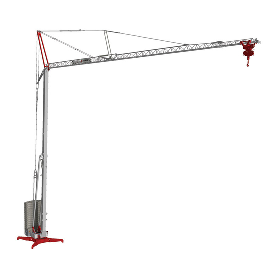
-
Contents
-
Table of Contents
-
Bookmarks
Quick Links
Self-Erecting
Tower Crane
CBR 40H
4
–
REV.000-1
O p e r a t i n g I n s t r u c t i o n s — I n s t a l l a t i o n
M a i n t e n a n c e
Related Manuals for Terex CBR 40H-4
Summary of Contents for Terex CBR 40H-4
-
Page 1
Self-Erecting Tower Crane CBR 40H – REV.000-1 O p e r a t i n g I n s t r u c t i o n s — I n s t a l l a t i o n M a i n t e n a n c e… -
Page 3
FOREWORD This publication must be read carefully by the personnel assigned to the crane before taking any action. Only by meticulously following the instructions given in this manual will the crane be able over time to provide the high performance for which it has been designed and constructed. The manual highlights important information for the safety of persons and conservation of the machine with the following wording: WARNING: When failure to observe or incorrect observation of the prescribed instructions… -
Page 4: Table Of Contents
TABLE OF CONTENTS T A B L E O F C O N T E N T S 1 MAIN CHARACTERISTICS page 1.1 MARKING 1.01 1.1.1 MANUFACTURER 1.01 1.1.2 TYPE OF MACHINE 1.01 1.1.3 CE MARKING 1.02 1.1.4 NOISE EMISSION MARKING 1.02 1.1.5 IDENTIFICATION PLATE…
-
Page 5
TABLE OF CONTENTS 1.4.5 MECHANISMS 1.22 1.4.5.1 HOISTING 1.22 1.4.5.2 TROLLEY TRAVERSING 1.23 1.4.5.3 SLEWING 1.23 1.4.5.4 ERECTION 1.24 1.4.6 HYDRAULIC DIAGRAM 1.25 1.4.7 PRECAUTIONS WHEN USING THE HYDRAULIC SYSTEM 1.26 1.4.8 CONTROL MEMBERS 1.27 1.4.8.1 MAIN SWITCH 1.27 1.4.8.2 PUSHBUTTON PANEL 1.28 1.4.9 COUNTERWEIGHT BALLAST… -
Page 6
TABLE OF CONTENTS 3 ERECTION — USE — DISMANTLING page 3.1 INSTRUCTIONS FOR POSITIONING AND ERECTION 3.01 3.1.1 ELECTRICAL CONNECTION 3.01 3.1.2 POSITIONING THE CRANE 3.04 3.1.3 PREPARING THE JIB 3.06 3.1.4 TOWER ERECTION 3.07 3.1.5 BALLASTING 3.08 3.1.6 JIB ALIGNMENT 3.10 3.2 SAFETY DEVICES — FUNCTION AND SETTING 3.13… -
Page 7
TABLE OF CONTENTS 4 MAINTENANCE page 4.1 MAINTENANCE INSTRUCTIONS 4.01 4.1.1 GENERAL 4.01 4.1.2 MAINTENANCE SCHEDULE 4.01 4.1.3 SLEWING RING 4.04 4.1.4 TROLLEY ROPE TENSIONING 4.04 4.1.5 CHECKING THE ROPES 4.05 4.1.6 LUBRICATION 4.06 4.1.7 STORING THE CRANE 4.06 4.2 INSTRUCTIONS FOR ROUTINE REPAIRS 4.07 4.2.1 GENERAL TROUBLE OF AN ELECTRICAL NATURE… -
Page 9: Main Characteristics
Self-Erecting Tower Crane CBR 40H – REV.000-1 — MAIN CHARACTERISTICS…
-
Page 11: Marking
TOWER CRANE intended to hoist off a rigid surface and move through the air an unguided unit load hanging directly from the hook with the permissible hoisting or slinging accessories in between. CBR 40H-4 MODEL….SERIAL No……….YEAR OF MANUFACTURE……
-
Page 12: Ce Marking
1 MAIN CHARACTERISTICS 1.1.3 CE MARKING The crane bears the CE marking for conformity with the Machinery Directive 98/37/EC and subsequent amendments. The marking is on the data plate on the door of the electric box The original signed «EC Declaration of Conformity» is delivered with the crane. This document is an integral part of the machine;…
-
Page 13: Identification Plate
1 MAIN CHARACTERISTICS 1.1.5 IDENTIFICATION PLATE The data plate shown below is on the door of the electric box. It bears the crane’s specifications as well as its identification data. The data plate is an integral part of the machine and must not be removed until the machine is dismantled.
-
Page 14: Foreword
1 MAIN CHARACTERISTICS FOREWORD 1.2.1 SCOPE AND LIMITS OF THE MANUAL This manual is mainly intended for the owners of cranes and their site managers and in general all operators involved in moving, installing, using and servicing the crane. The purpose of this manual is to provide information on: •…
-
Page 15: Supplements And Updates To The Manual
1 MAIN CHARACTERISTICS 1.2.3 SUPPLEMENTS AND UPDATES TO THE MANUAL This manual represents the state of technology at the time of marketing the crane to which it refers; it must not be considered inadequate just because it has been subsequently updated in the light of new experience. Comedil reserves the right to modify its production and associated manuals without moreover being bound to update what was previously delivered.
-
Page 16: Intended Conditions Of Use
1 MAIN CHARACTERISTICS INTENDED CONDITIONS OF USE 1.3.1 DESCRIPTION OF THE EQUIPMENT The tower crane described in this manual is a device for hoisting and transportation intended solely for professional use. General characteristics: • slewing: at the bottom • installation method: in fixed position •…
-
Page 17
1 MAIN CHARACTERISTICS 1000 kg 38.8 m 1000 kg 39.5 m WARNING: When the jib is raised by 10° and 15° it is permissible to use the 2-part line only. CBR 40H page 1.07 rev. 40H_1i_07… -
Page 18
1 MAIN CHARACTERISTICS CAPACITY DIAGRAMS Radius 40 m 2/4-part line 4000 3000 2500 2000 1850 1600 1200 1000 13.0 16.5 19.2 23.0 24.5 27.6 34.7 raised 10° (2-part line only) 2000 1850 1600 1200 1000 22.7 24.2 27.3 34.3 39.5 raised 15°… -
Page 19
1 MAIN CHARACTERISTICS movement speed (m/min) capacity (kg) power (kW) micro 6 2000 2-part line slow 23 2000 fast 1000 HOISTING micro 3 4000 4-part line slow 11.5 4000 fast 2000 TROLLEY TRAVERSING 16 / 46 4000/2000 SLEWING 0.3 — 0.9 rpm 1.1 (6 daNm) ERECTION Necessary electric power at… -
Page 20: Operating Environment
1 MAIN CHARACTERISTICS 1.3.4 OPERATING ENVIRONMENT The recommended operating environment is the following: temperature — 5 to 40 °C maximum relative humidity maximum wind speed: • in operation 72 km/h • during erection 30 km /h • out of service 102 km/h on the ground 151 km/h above 20 m in height 1.3.5…
-
Page 21: Operational Control
1 MAIN CHARACTERISTICS 1.3.8 OPERATIONAL CONTROL The operator must always have a direct view of both the load, from gripping to depositing, and the sling. In addition, all the movable parts of the equipment must be visible. If the load is not visible, the operator must receive the operating instructions from an appointed person trained for this function who can see the load.
-
Page 22: Control Elements
1 MAIN CHARACTERISTICS 1.3.9 CONTROL ELEMENTS 1.3.9.1 Pushbutton panel with cable The pushbutton panel is equipped with recessed operating buttons bearing the symbol of the control and an emergency (mushroom-head) button, equipped with an automatic shutdown and reset device with intentional operation. NOTE: The crane can also be operated with a radio-controlled pushbutton panel or manipulator.
-
Page 23: Stopping Movements
1 MAIN CHARACTERISTICS 1.3.11 STOPPING MOVEMENTS The movements are intentionally stopped by releasing the respective control buttons or operating the emergency stops. The up and down movements and the movements of trolley traversing and slewing are progressively stopped in a preset time controlled by an inverter; the mechanical brake only triggers after the movement has stopped.
-
Page 24: Permissible Hoisting Accessories
1 MAIN CHARACTERISTICS 1.3.13 PERMISSIBLE HOISTING ACCESSORIES The hoisting accessories must have a suitable capacity for the extent of the loads to hoist. Hoisting accessories that are simply, in a passive manner, placed between the hook and the load are generally permissible, such as for example: manual opening grabs, forks for pallets, baskets, etc.
-
Page 25: Potential Non-Permissible Uses Of The Cranes
1 MAIN CHARACTERISTICS 1.3.15 POTENTIAL NON-PERMISSIBLE USES OF THE CRANES (see attached diagrams) 1000 4000 1100 4100 Do not hoist loads that exceed the crane’s capacity. Do not hoist at an angle or tow the load. Do not use «rapid» hoisting for loads greater than the permissible ones.
-
Page 26
1 MAIN CHARACTERISTICS Do not lift the load off unstable supporting Do not lift loads hooked outside the surfaces (dangerous scaffolding, watercraft axis of the centre of gravity when there may etc). be tipping over or wild swinging of the load Do not swing a hanging load to deposit Do not make any up or down movements it outside the crane’s range of action. -
Page 27
1 MAIN CHARACTERISTICS Do not use the counter-manoeuvre (do not start Do not pass the load over work areas a manoeuvre if the dynamic effects of the opposite or passageways. preceding manoeuvre have not ended). Do not make any manoeuvres with the load in a Do not affix on the equipment any banners, signs, position where it is not visible. -
Page 28
1 MAIN CHARACTERISTICS Never tow the crane (on rollers or the like) Do not unload from vehicles any weights greater when erected (for working requirements in larger areas) than those permitted by utilizing the forward movement of the vehicle. Do not use the crane for demolition in general. Do not leave the hook constrained to a weight resting or stuck on the ground when the crane is out of service. -
Page 29: Technical Description
1 MAIN CHARACTERISTICS TECHNICAL DESCRIPTION 1.4.1 MAIN COMPONENTS The main components of the crane are listed and identified in the following diagram Undercarriage with arms, screw jacks and stabilizer supports. Platform with slewing unit, hydraulic power pack and electrical equipment Ballast composed of erection block and completion blocks Lower tower section…
-
Page 30: Description Of The Structures
1 MAIN CHARACTERISTICS 1.4.2 DESCRIPTION OF THE STRUCTURE The fixed undercarriage and revolving slewing platform are composed of electric welded plates and sections and are constrained together by the slewing ring. The surfaces are protected by painting composed of a rustproofing coat on which a coat of synthetic paint is applied.
-
Page 31
1 MAIN CHARACTERISTICS 1.4.4.1 Rope diagram 1.4.4.1 Rope diagram TROLLEY ROPE HOISTING ROPE Rope socket 2-PART LINE 4-PART LINE Hoisting rope drum Trolley rope drum CBR 40H page 1.21 rev. 40H_1i_21… -
Page 32
1 MAIN CHARACTERISTICS 1.4.5 MECHANISMS 1.4.5.1 Hoisting The hoisting winch is fitted on the lower tower section and comprises: motor , three-phase, asynchronous, self-braking, 4 poles, 8.8 kW, with twin disc with two braking surfaces; reduction gear, with orthogonal axes and cylindrical gears in cast-iron casing, with hollow shaft and flange at motor input and output shaft for drum, reduction ratio 1/30;… -
Page 33
1 MAIN CHARACTERISTICS 1.4.5.2 Trolley traversing The trolley traversing winch is fitted on a frame bolted onto the jib structure and comprises: Motor (1), three-phase, asynchronous, self-braking, 4 poles, 3 kW, with disc brake with two braking surfaces; reduction gear (2), orthogonal with gears in cast-iron casing, with hollow shaft and flange at motor input and output shaft for drum, reduction ratio 1/41;… -
Page 34
1 MAIN CHARACTERISTICS 1.4.5.4 Erection Erection of the crane is hydraulic; a power pack operates 3 cylinders that permit aligning (and folding) the towers and jib. The hydraulic power pack is located on the revolving slewing platform and comprises: motor , three-phase, asynchronous, 4 poles, 2.2 kW 2 gear pumps , delivery 2 and 4 l/min reservoir 90 l with level indicator 3 control valves with 3 positions with solenoid valves… -
Page 35
1 MAIN CHARACTERISTICS 1.4.6.1. HYDRAULIC DIAGRAM CYLINDER JIB END SECTION CYLINDER JIB TAIL SECTION CYLINDER TOWER CBR 40H page 1.25 rev. 40H_1i_25… -
Page 36
1 MAIN CHARACTERISTICS 1.4.7 PRECAUTIONS WHEN USING THE HYDRAULIC SYSTEM Before setting the hydraulic system in operation it is necessary to check the fluid level with the level indicator plug on the power pack reservoir and, if necessary, top it up. CAUTION: An insufficient amount of oil in the reservoir can cause erection to stop and damage the pump of the hydraulic power pack. -
Page 37
1 MAIN CHARACTERISTICS 1.4.8 CONTROL ELEMENTS 1.4.8.1 Main switch The main switch is inside the electric box and can be operated from the outside with a knob on the door. It permits cutting off power to the equipment and to all the devices connected to The switch has two positions, off-on, marked by the symbols “O”… -
Page 38
1 MAIN CHARACTERISTICS 1.4.8.2 Pushbutton panel The pushbutton panel is equipped with a cable and plug and it can be connected either to the socket under the electric box or to the one on the fixed undercarriage. The red mushroom-head STOP button must be turned clockwise to be released. Simply pressing the green START / ALARM button enables all the movement controls and operates the audible warning. -
Page 39
1 MAIN CHARACTERISTICS 1.4.9 COUNTERWEIGHT BALLAST The counterweight ballast is composed of two erection blocks and 13 completion blocks. The erection blocks are an integral part of the crane and remain in position during transport too. The completion blocks are supplied and transported separately. They are composed of slabs of reinforced concrete weighing 1,550 kg each and they should be positioned after straightening the towers. -
Page 40
1 MAIN CHARACTERISTICS 1.4.9.1 COMPLETION BLOCKS Weight of block kg 1550 ± 30 Density 2450 kg/m3 CBR 40H page 1.30 rev. 03_05 40H_1i_30… -
Page 41
Self-Erecting Tower Crane CBR 40H – REV.000-1 — SITE PREPARATION — TRANSPORTATION… -
Page 43
2 SITE PREPARATION — TRANSPORT SITE PREPARATION Site preparation is to be done and paid for by the user and it must be accomplished before the arrival of the crane. 2.1.1 ERECTION CLEARANCES It is first of all necessary to make sure that the minimum clearance needed to erect and dismantle the crane is free from all obstructions. -
Page 44
2 SITE PREPARATION — TRANSPORT The maximum load on each support is 29,500 daN (approximately 30,000 kg). The plinths must be positioned at such a distance from the excavations as to ensure that the load on the supports causes no subsidence of the ground even in the event of long periods of rain. -
Page 45
2 SITE PREPARATION — TRANSPORT 2.1.4 PROTECTION FROM ATMOSPHERIC DISCHARGE The sizing, construction, testing and servicing of the systems protecting against atmospheric discharge must meet the prescriptions of the CEI 64-8 and CEI 81-1 standards. It is recommended to utilize qualified firms that can guarantee compliance of the system with the above or other standards or laws in force in the country where the crane is used. -
Page 46
2 SITE PREPARATION — TRANSPORT 2.1.6 COUNTERWEIGHT BALLAST The counterweight ballast, on the rotating undercarriage, is generally supplied with the crane; if you have any special requirements, you must contact Comedil directly. When the crane arrives on site, make sure you have suitable equipment for lifting 1550 kg (weight of each block). -
Page 47
2 SITE PREPARATION — TRANSPORT 2.1.10 SAFETY SIGNS The specific signs for the crane must be displayed on the site. For example, these are some of the main signs to display: • beware of hanging loads • no entry (to be put up at the crane fencing entrance) •… -
Page 48
2 SITE PREPARATION — TRANSPORT INSTRUCTIONS FOR TOWING AND TRANSPORT 2.2.1 TOWING CONDITIONS WARNING: Towing the crane is only permissible on site with a self-propelled vehicle that is type-approved for towing a trailer of weight equal to or greater than that of the crane. Towing on roads is only permissible if the crane is equipped with type-approved braking system and lights. -
Page 49
2 SITE PREPARATION — TRANSPORT Before commencing towing, make sure that: • the tyre pressure corresponds to the indications of the chart in point 2.2.5; • the hoisting block assembly is suitably fastened; • all parts that could move are secured in a safe and stable manner; •… -
Page 50
2 SITE PREPARATION — TRANSPORT 2.2.6 SPECIAL INSTRUCTIONS The wheel fastening is shown in the figure and must always be done by placing the washer with the ball support in between towards the rim. Before travelling each time it is advisable to check the tightness of the nuts and the pressure of the tyres. -
Page 51
2 SITE PREPARATION — TRANSPORT 2.2.8 TRANSPORT The crane can be transported, dismantled, on a vehicle with a deck of suitable dimensions. The overall dimensions of the crane are given in the figure. Loading and unloading the crane on and off the vehicle must be done by using the specific hooks on the crane with slings suited to withstand a balanced load of 22,000 kg or by using the vehicle’s runways In this case, with the aid of two hydraulic jacks, it is necessary to bring the axles back into the towing position by… -
Page 52
2 SITE PREPARATION — TRANSPORT STRUCTURES AND METHODS OF ACCESS The crane is automatic and self-erecting, as a result all servicing operations to be performed on the ground with the crane dismantled. Climbing on the crane is not permitted. In the event of special maintenance work on parts that are not accessible from the ground it is obligatory to use a suitable platform or extending scaffolding. -
Page 53
Self-Erecting Tower Crane CBR 40H – REV.000-1 — ERECTION — OPERATION — DISMANTLING… -
Page 55
3 ERECTION — USE — DISMANTLING INSTRUCTIONS FOR POSITIONING AND ERECTION The erection operations must be performed by specially trained personnel belonging to the Comedil After-Sales organization as prescribed in point 1.2.1. Personnel assigned to erection must be equipped with at least the following personal protective equipment: •… -
Page 56
3 ERECTION — USE — DISMANTLING Open the door of the electric box and turn the switch (1) onto the ERECTION position. Close the door of the electric box and turn the main switch (2) onto «I». Press the green START / ALARM button of the pushbutton panel (3): the sound of the horn warns of the activation of the electrical equipment and all the devices connected to it. -
Page 57
3 ERECTION — USE — DISMANTLING Press ERECTION and check that the hydraulic power pack motor fan (1) turns in the direction shown by the arrow. If it is necessary to invert the phases, cut off power to the site’s distribution board. -
Page 58
3 ERECTION — USE — DISMANTLING 3.1.2 POSITIONING THE CRANE Open the two rear undercarriage arms (1), ballast side, and secure them in the working position with the pins (2). Open the two front undercarriage arms (3), tower side, arranging them as shown in the figure. -
Page 59
3 ERECTION — USE — DISMANTLING Turn the cylinder selector knob onto position 1. Operate the ERECTION control until the front stabilizers are firmly resting on the wooden boards. Level the undercarriage (check with a spirit level) crossways by adjusting the screw jacks. -
Page 60
3 ERECTION — USE — DISMANTLING 3.1.3 PREPARING THE JIB Before proceeding with erection, make sure that the rear tie-rod and the capacity signs are ready for the required set-up. The crane can also work with the jib raised by 10° or 15° and/or folded back as indicated in point 1.3.3 «Range of Set-Ups.»… -
Page 61
3 ERECTION — USE — DISMANTLING 3.1.4 TOWER ERECTION Continue with ERECTION checking that the pressure on the gauge does not exceed 270 bar. When the rear axle loses its load, remove the pins (1) securing it to the lower tower section. -
Page 62
3 ERECTION — USE — DISMANTLING 3.1.5 BALLASTING Before carrying out any other operations, it is necessary to complete the crane ballasting. Here we describe the operation of using the self-ballasting device (DAZ) supplied as an option with the crane. If there is no DAZ it is necessary to use lifting equipment (crane truck, fork-lift truck, etc.) with a capacity greater than the weight of each block. -
Page 63
3 ERECTION — USE — DISMANTLI NG On completing the operation of positioning all the blocks, unhook the ring (1) of the self-ballasting rope (2) from the work hook. Pull the other end of the rope until the ring rests on the idle pulley (3). Insert the rope through the pegs of the blocks hooking the end hook to one peg, as shown in the figure, so that the rope stays slightly taut. -
Page 64
3 ERECTION — USE — DISMANTLING 3.1.6 JIB ALIGNMENT WARNING: Make sure that all the required ballast has been loaded; opening the jib without ballast causes the crane to tip over. WARNING: Make sure that above the jib there are no obstacles such as electricity cables or jibs of other cranes. -
Page 65
3 ERECTION — USE — DISMANTLING Continue the movement until cylinder 2 is fully extended. After completing the operation, stop when the pressure has risen to approximately 200 bar; this ensures the cylinder has reached its limit stop. NOTICE: The crane can work with the jib end section folded back (see 1.3.3); in this case, set the safety devices as indicated in point 3.2. -
Page 66
3 ERECTION — USE — DISMANTLING To complete jib alignment, it is necessary to switch the cylinder selector onto position 3 (cylinder 3) and operate ERECTION. Continue the movement until cylinder 3 is fully extended. After completing the operation, stop when the pressure has risen to 200 bar; this makes sure the cylinder has reached its limit stop. -
Page 67
3 ERECTION — USE — DISMANTLING SAFETY DEVICES — FUNCTION AND SETTING Whenever erecting the crane, before putting it into service, it is always necessary to set the safety devices as described in the following paragraphs. The setting of the safety devices must be checked and corrected also in the event of changing the arrangement of the jib with the crane erected such as passing from an aligned jib to a folded jib or vice versa. -
Page 68
3 ERECTION — USE — DISMANTLING 3.2.1 POSITION OF THE SAFETY DEVICES ON THE CRANE STATIC MOMENT limiter DYNAMIC MOMENT limiter HIGH SPEED limiter MAXIMUM LOAD limiter UP limit switch DOWN limit switch NEAR limit switch DISTANT limit switch PRE-SLOWDOWN limit switch LEFT SLEWING limit switch RIGHT SLEWING limit switch CBR 40H… -
Page 69: Static Moment Limiter U8
3 ERECTION — USE — DISMANTLING 3.2.2 STATIC MOMENT LIMITER U 8 Function The limiter U8 is positioned on the vertical tie-rod; it blocks the DISTANT movement if the load permitted by the load diagram is exceeded (see point 1.3.3). To restore the movement it is necessary to reduce the load or reduce the radius by operating NEAR.
-
Page 70: 2 Dynamic Moment Limiter U3
3 ERECTION — USE — DISMANTLING 3.2.3 DYNAMIC MOMENT LIMITER U 3 Function The limiter U3 is positioned on the vertical tie-rod; it blocks the UP and DISTANT movement if the load permitted by the load diagram is exceeded (see point 1.3.3).
-
Page 71: 3 High Speed Limiter U5
3 ERECTION — USE — DISMANTLING 3.2.4 HIGH SPEED LIMITER (GV) U 5 Function The limiter U5 is positioned on the hoisting motor; it blocks the HIGH SPEED UP movement if the load permitted with this operation is exceeded (see point 1.3.3). To restore the movement it is necessary to reduce the load.
-
Page 72: 4 Maximum Load Limiter U4
3 ERECTION — USE — DISMANTLING 3.2.5 MAXIMUM LOAD LIMITER U 4 Function The limiter U 4 is positioned on the hoisting motor; it blocks the UP movement if the load permitted with this operation is exceeded (see point 1.3.3). To restore the movement it is necessary to reduce the load.
-
Page 73: Up Limit Switch U1
3 ERECTION — USE — DISMANTLING 3.2.6 UP LIMIT SWITCH U1 Function The limit switch U1 is positioned on the drum of the hoisting winch; it blocks the UP movement when the block assembly reaches the position for the setting. Checking and Setting The setting of the limit switch U1 must be checked by hoisting the block assembly near to the trolley and proceeding as follows:…
-
Page 74: Down Limit Switch
3 ERECTION — USE — DISMANTLING 3.2.7 DOWN LIMIT SWITCH U2 Function The limit switch U2 is positioned on the drum of the hoisting winch (together with U1); it blocks the DOWN movement when the block assembly reaches the position for the setting. Checking and Setting The setting of the limit switch U2 must be checked by lowering the block assembly near to the ground and proceeding as follows:…
-
Page 75
3 ERECTION — USE — DISMANTLING 3.2.8 TROLLEY LIMIT SWITCH ( U6, U7, U9) Function The trolley limit switch, (U6 NEAR – U7 DISTANT – U9 PRE-SLOWDOWN), of the worm screw type, is located on the tower coaxial with the shaft of the trolley drum;… -
Page 76
3 ERECTION — USE — DISMANTLING 3.2.9 SLEWING LIMIT SWITCH U13 — U14 Function The limit switch U13-U14 is positioned on the slewing platform by the slewing ring; it blocks the LEFT or RIGHT movement when approximately 2 consecutive turns have been made in the same direction. Checking and Setting Limit switch U13 is checked by operating the LEFT control to make two consecutive turns in the same direction;… -
Page 77
3 ERECTION — USE — DISMANTLING BRAKES — CHECKING AND SETTING The electric motors, for hoisting, trolley traversing and slewing, are equipped with disc brakes. Before putting the crane into operation it is necessary to check that the brakes are efficient, correcting the braking torque and the air gap if necessary. -
Page 78
3 ERECTION — USE — DISMANTLING To adjust the air gap, proceed as follows: • remove the cap (1); • loosen the fixing nuts (2) and turn them to move the electromagnet (3) nearer or further away to reach the correct adjustment; •… -
Page 79
3 ERECTION — USE — DISMANTLING GENERAL OPERATING INSTRUCTIONS 3.4.1 BEFORE PUTTING INTO SERVICE The crane can be put INTO OPERATION only when it is in a perfect state of efficiency; if this is not so, it must be prevented from being used until optimum conditions are restored. -
Page 80
3 ERECTION — USE — DISMANTLING Slewing controls Starting, changing speed and stopping the RIGHT and LEFT movements take place progressively and are controlled electronically by a frequency convertor (inverter). When stopping the manoeuvre it is necessary to consider the braking distance needed to stop the load in the required position. -
Page 81
3 ERECTION — USE — DISMANTLING SWITCHING OVER 2/4-PART LINES The crane can be equipped with a trolley and block assembly fitted for both 2 and 4 part ropes (2/4-PART LINE). Switching over from a 2-part line to a 4-part line •… -
Page 82
3 ERECTION — USE — DISMANTLING DISMANTLING INSTRUCTIONS The dismantling operations must be performed by specially trained personnel belonging to the Comedil After-Sales organization as prescribed in point 1.2.1. Personnel assigned to dismantling must be equipped with at least the following personal protective equipment: •… -
Page 83
3 ERECTION — USE — DISMANTLING Switch the cylinder selector onto position 2 (cylinder 2) and operate the DISMANTLING control checking that the pressure does not exceed 250 bar. WARNING: At the start of the folding phase, check the arrangement of the hoisting ropes and trolley, making sure the hoisting rope does not enter the races of the pulleys engaged by the trolley rope. -
Page 84
3 ERECTION — USE — DISMANTLING Briefly operate ERECTION until the pressure has risen to 150 bar. Operate the DISMANTLING control to close the towers. Check that no obstructions are encountered as the jib and towers come down and that the block assembly stays outside the towers. CAUTION: Throughout the dismantling phase, never operate the DISTANT or NEAR control;… -
Page 85
Self-Erecting Tower Crane CBR 40H – REV.000-1 — MAINTENANCE… -
Page 87
4 MAINTENANCE MAINTENANCE INSTRUCTIONS 4.1.1 GENERAL Operational reliability, safety and durability of the machine largely depend on thorough maintenance. Maintenance performed regularly at the required intervals contributes to considerably increase the durability and value of the crane. Besides the normal checks required by current regulations, it is necessary for the user to schedule periodical servicing to be performed by his own personnel in charge of maintenance. -
Page 88
4 MAINTENANCE MAINTENANCE INTERVALS maintenance operations assembly COMPLETE CRANE inspection of all constructional parts SLEWING grease Slewing ring check tightness Check clearance between the two rings Crown wheel spray with grease spray Reduction gear check level change oil Brake check gap HOISTING check level Reduction gear… -
Page 89
4 MAINTENANCE MAINTENANCE INTERVALS maintenance operations assembly ROPES check there are no knots, yielding or breakage check the fastenings, winding on pulleys and drum have specialized personnel check clean and grease check the trolley rope tension MECHANICAL PARTS Pins check positioning in seat and split pins Screws check integrity of fastenings Pivot pins… -
Page 90
4 MAINTENANCE 4.1.3 SLEWING RING The slewing ring is fastened to the structure by M 22 high-strength bolts, tightened with a torque wrench to a setting of 50 daN.m. This tightness must be checked within the first month of work and every 3 months thereafter by specialized personnel authorized by Comedil. -
Page 91
4 MAINTENANCE 4.1.5 CHECKING THE ROPES To ensure the greatest working safety for site personnel it is essential for all ropes installed on the crane to be in a good state of repair and show no sign of wear, corrosion or strands breaking. It is necessary to inspect the ropes every day, checking the general conditions of deterioration and deformation, replacing them immediately if they no longer meet the safety requirements;… -
Page 92
4 MAINTENANCE 4.1.6 LUBRICATION The lubrication of the various parts of the crane must be done at regular intervals as directed in the maintenance schedule. The chart indicates the types of lubricant to use for each component of the crane; using lubricants other than the ones indicated here can impair the good operation of the machine. -
Page 93
4 MAINTENANCE INSTRUCTIONS FOR ROUTINE REPAIRS There follows a list of the simplest and most common faults that can be resolved directly on site without requesting assistance from the Service Centre. 4.2.1 GENERAL TROUBLE OF AN ELECTRICAL NATURE One of the crane movements does not work, there is not the noise of the electric disc brake opening, but the related electric contactors work correctly: The associated fuse or miniature circuit breaker might have tripped, due to a… -
Page 94
4 MAINTENANCE The controls are uncertain: The contacts of the buttons of the control element might be oxidized: polish them. The cable of the control element might have a broken conductor. Operating a control immediately, or very quickly, causes the residual current device of the site panel to trip: There is dispersion of electric current to ground: find the fault on the supply line or on the motor of the movement causing the RCD to trip. -
Page 95
4 MAINTENANCE 4.2.3 ELECTRICAL TROUBLE WITH TROLLEY TRAVERSING The «DISTANT» movement does not work: One of the following devices or the relative electric circuit is broken: distant limit switch, moment limiter with tripping on the distant movement. The «NEAR» movement does not work: The limit switch or its electric circuit is broken. -
Page 96
4 MAINTENANCE 4.2.6 MISCELLANEOUS OPERATIONAL TROUBLE The block assembly moves irregularly, especially down with no load: there might be difficulty with the rotation of a pulley due to rubbing on the support or a bearing jamming: remove the cause of the difficulty with rotation. -
Page 97
4 MAINTENANCE INSTRUCTIONS FOR REMAINING HAZARDS The user must be aware that using hoisting equipment, which is intended solely for professional use, exposes him to remaining hazards of the equipment; these hazards cannot be eliminated or sufficiently reduced with the design and against which the protection and guards are either not effective completely… -
Page 98
4 MAINTENANCE Hazards deriving from protruding parts of the machine: concerns the area nearby the crane, especially during maintenance work and installation. • during the normal work cycles, prevent access to the area covered by the slewing of the crane. •… -
Page 99
4 MAINTENANCE Hazards deriving from static electricity: involve cranes installed near transmitters; in this case there may be an accumulation of static electricity on the crane that is not discharged through the machine’s grounding system, with the result that there can be potential on the crane’s hook that is not the same as the ground potential with the risk of electric shock when the operator touches the hook or the load connected to it. -
Page 100
4 MAINTENANCE TRAINING PERSONNEL Generally, no particular information is provided for training for erection and maintenance work since these operations are reserved for specialized personnel. Operator training must take place in conformity with the UNI-ISO 9926/1 and 9926/3 standards that must be known. When choosing the operator, who must be at least 18 years old, it is necessary to consider: a) physical aspect:… -
Page 101
4 MAINTENANCE DEMOLISHING THE EQUIPMENT If the crane is registered with public offices it is mandatory to report its demolition in accordance with current regulations, attaching the official documents and the identification plate It should be considered that the crane is composed of: •…
Автокраны серии T 500
СЕРИЯ Т 500
Автокраны
ФУНКЦИИ И ОСОБЕННОСТИ
· Максимальная грузоподъемность 50 тонн (45 тонн)
· Максимальная длина стрелы 110 футов (33.5 м)
· Максимальная высота наконечника 169 футов (51.5 м)
· Полноприводная четырехсекционная стрела с механической синхронизацией и одним рычагом
управление · поворотная стрела со смещением
0°, 15° или 30°
· Двухскоростные основная и вспомогательная лебедки
· Быстрозапасательная головка стрелы и блок крюка
· Полностью независимые многопозиционные выносные и опускаемые аутригеры
· Экологичная кабина оператора оптимизирует обзор груза и производительность
· Система нагрузки RCI 500 Индикатор номинальной грузоподъемности
· Скорость движения до 65 миль в час (105 км/ч)
· Стандартная пневматическая подвеска для передних осей, опционально для задних
· Легко читаемые книги с таблицами нагрузок включают диаграммы диапазонов
· Гарантия 12 месяцев или 2000 часов, на основные сварные детали — 5 лет или 10,000 XNUMX часов
простой, доступный и экономичныйTM
https://www.besttruckmanuals.com/
Показанные машины могут иметь дополнительное оборудование.
СЕРИЯ TEREX T 500
Автокраны
Т 500 50 тонн (45 тонн)
110 футов. (33.5 м) ЧЕТЫРЕХСЕКЦИОННАЯ, ПОЛНАЯ МОЩНОСТЬ,
МЕХАНИЧЕСКИ СИНХРОНИЗИРОВАННАЯ СТРЕЛА С ОДНОРЫЧАЖНЫМ УПРАВЛЕНИЕМ
· Высокопрочная конструкция из четырех пластин, сваренных внутри и снаружи, с рельефными отверстиями в боковых пластинах для уменьшения веса и увеличения прочности.
· Один цилиндр подъема стрелы обеспечивает угол подъема стрелы от -4° до 76°, что упрощает замену запаски и работу с малым радиусом действия.
· Быстрозапасательная головка стрелы; нет необходимости вынимать клин из гнезда.
· Стандарт замка дома 360°.
ЭКОЛОГИЧЕСКАЯ КАБИНА ОПЕРАТОРА
· Система индикации номинальной мощности (RCI), включая систему защиты от двух блоков с функцией автоматического отключения.
· Сиденье оператора повышенной комфортности с регулировкой в шести направлениях имеет торсионную подвеску и регулируемые подголовник и подлокотники.
· Звуковая и погодная изоляция для комфорта.
· Съемное переднее окно, тонированное стекло на петлях и сдвижное правое окно
окно. · Ручные рычаги управления качанием,
телескоп стрелы, подъемник стрелы и однорычажная двухскоростная основная лебедка; педали ножного управления для поворотного тормоза и подъема стрелы, опускания стрелы и газа.
· Полный инструментарий. Кулисные переключатели с защитой от воздействия окружающей среды. Автоматические выключатели в кабине.
ПРОЧНЫЙ, ЛЕГКИЙ В МАНЕВЕРЕ
ПЕРЕВОЗЧИК
· Шасси спроектировано и изготовлено компанией Terex с приводом 8 x 4.
· Полный алюминиевый настил снижает вес.
· В настил встроено несколько запираемых отсеков для хранения вещей, а также дополнительные органы управления выносными опорами с уровня земли.
· Стандартная 10-ступенчатая механическая коробка передач, автоматическая коробка передач CEEMAT
трансмиссия опционально. · Стандартная пневматическая подвеска на передних осях,
опционально на задние оси.
· Полностью пневматические тормоза на всех колесах с раздельной системой.
· Полностью независимые гидравлические выносные опоры можно использовать полностью выдвинутыми до 21 фута (6.40 м), в выдвинутом на 1/2 положении или полностью убранными.
· Стандартный двигатель Detroit Diesel Series 50.
· Стандартный тахометр и алюминиевые диски.
PWOINWCEHREFSUL, ДВУХСКОРОСТНАЯ
· Максимальная линейная скорость 533 футов в минуту (162 м/мин), 15,639 7093 фунтов. (XNUMX кг) максимальное тяговое усилие. Однорычажное управление.
· Встроенный автоматический тормоз.
· Электронные барабанные индикаторы.
· Ролики барабана лебедки, конические фланцы барабана.
НАДЕЖНАЯ ГИДРАВЛИЧЕСКАЯ СИСТЕМА ВЫСОКОЙ ПРОИЗВОДИТЕЛЬНОСТИ
· Три шестеренчатых насоса с приводом от картера маховика двигателя. Производительность комбинированной системы составляет 115 гал/мин (435 л/мин).
· Гидравлический резервуар на 114 галлонов. (443 л) и полнопоточная система фильтрации масла.
ВАРИАНТЫ ВКЛЮЧАЮТ:
· 32 фута или от 33 до 57 футов (9.68 или от 10.15 до 17.30 м) поворотная стрела. Оба смещения 0°, 15° или 30°.
· Вспомогательная лебедка с тросом.
· oHpeeartaetro/dr’esfrcoasbt;ear,iraicrocnodnitdiiotinoenrefroforcarrier кабина.
· Тяжелый противовес с гидравлической системой снятия.
· Комплект для холодной погоды для кабины.
· Двигатель Detroit Diesel Series 60.
Для получения дополнительной информации, демонстрации продукта или подробностей о планах покупки, аренды и аренды обращайтесь к местному дистрибьютору Terex Cranes.
Мы оставляем за собой право изменять эти спецификации в любое время без предварительного уведомления. Единственной применимой гарантией является наша стандартная письменная гарантия, применимая к конкретному продукту и продаже. Мы не даем никаких других гарантий, явных или подразумеваемых.
TC-504
106 12th Street SE Waverly, IA 50677-9466 США (319) 352-3920 · ФАКС: (319) 352-5727 Электронная почта: waverly@terexlifting.com
https://www.besttruckmanuals.com/
©Terex Cranes, Inc., 2000 г.
Лито в США
www.terexlift.com
10У100Т34
https://www.besttruckmanuals.com/
https://www.besttruckmanuals.com/
https://www.besttruckmanuals.com/
https://www.besttruckmanuals.com/
https://www.besttruckmanuals.com/
https://www.besttruckmanuals.com/
https://www.besttruckmanuals.com/
https://www.besttruckmanuals.com/
https://www.besttruckmanuals.com/
https://www.besttruckmanuals.com/
https://www.besttruckmanuals.com/
https://www.besttruckmanuals.com/
Документы / Ресурсы
Рекомендации
- Саламов Игорь
- 22. Сверхразум (97403)
- 4 года
Модератор проекта «Ноль вопросов!», также увлекаюсь программированием
Бесплатно есть к AC 45 не подойдет? Внешне с AC 40 они очень похожи. Вот руководство на официальном сайте производителя https://www.terex.com/demag/ru/product/city-crane/ac-45-city Когда перейдете по ссылке на странице увидите три закладки «Характеристики, Загрузки, Преимущества», выберите закладку «Загрузки», появятся две ссылки на руководства, одна на чистом английском, другая на семи языках включая русский, вот её и откройте. Вот на всякий случай загрузил в облако: https://cloud.mail.ru/public/8Zef/myWm2TSsJ На AC 40 нашел только платно стоит она 400 рублей, здесь: https://texbooks.ru/search/Terex%20Demag%20AC%2040
П
- Пыжьянов Демид
- 1. Новичок (0)
- 3 года
Пользователь
Добрый день, ищу устройство крана и платформы Demag AC 265 не подскажите где найти?

размещено: 09 Октября 2018
Паспорт башенного крана TEREX CTT181.
Порядок:
от старых к новым

3.01 МБ
СКАЧАТЬ
TEREX-COMEDIL CTT 91-5. Кран башенный с неповоротной башней. Паспорт

чтобы посмотреть нажмите «дальше»
Автор:
Alex
![]()
Ярлыки:
Башенный кран,
TEREX
- Manuals
- Brands
- Terex Manuals
ManualsLib has more than 1353 Terex manuals
Accessories
Genie Lift Guard S-40
Operator’s Manual Supplement
• Operator’s Manual
• Maintenance Manual
• Service And Repair Manual
• Maintenance Manual
• Maintenance Manual
Genie Lift Guard S-45
Operator’s Manual Supplement
• Operator’s Manual
• Maintenance Manual
• Service And Repair Manual
• Maintenance Manual
• Maintenance Manual
Genie Lift Guard S-60
Operator’s Manual Supplement
• Maintenance Manual
• Service Manual
• Maintenance Manual
• Maintenance Manual
Genie Lift Guard S-65
Operator’s Manual Supplement
• Maintenance Manual
• Service Manual
• Maintenance Manual
• Maintenance Manual
Automobile
TR100
Operation Manual
• Maintenance Manual
Boom Lifts
C5000 Series
Tech Tips
• Tech Tips
• Quick Start Manual
C6000 Series
Tech Tips
• Tech Tips
• Quick Start Manual
Genie 20N RJ
Service And Repair Manual
Genie GR-20J
Service Manual
• Service Manual
Genie GR-26J
Service Manual
• Service Manual
• Operator’s Manual
Genie GS-1530
Operator’s Manual
• Operator’s Manual
• Service And Repair Manual
• Maintenance Manual
• Service And Repair Manual
• Operator’s Manual
• Service And Repair Manual
• Maintenance Manual
• Service Manual
Genie GS-1532
Operator’s Manual
• Operator’s Manual
• Service And Repair Manual
• Maintenance Manual
• Service And Repair Manual
• Operator’s Manual
• Service And Repair Manual
• Maintenance Manual
• Service Manual
Genie GS-1930
Operator’s Manual
• Operator’s Manual
• Service And Repair Manual
• Maintenance Manual
• Service And Repair Manual
• Operator’s Manual
• Service And Repair Manual
• Maintenance Manual
• Service Manual
Show all Terex Boom Lifts manuals
Cables and connectors
Caravans
T12009-000101
Service Manual
T120C
Operator’s Manual
• Service Manual
T7009-000101
Service Manual
T70C
Operator’s Manual
• Service Manual
T70P
Operator’s Manual
• Service Manual
T9009-000101
Service Manual
T90C
Operator’s Manual
• Service Manual
T90P
Operator’s Manual
• Service Manual
Compact Loader
ASV SR70
Service & Repair Manual
DTM 00101 (standard)
Operation And Maintenance Manual
DTN 00101 (forestry)
Operation And Maintenance Manual
Genie GTH-4013
Operator’s Manual
• Service Manual
Genie GTH-4017 EX
Service Manual
Genie GTH-4514 EX
Service Manual
PT-100G F
Operation And Maintenance Manual
Show all Terex Compact Loader manuals
Construction Equipment
360310
Operating Instructions Manual
3B6
User Manual
• Troubleshooting Manual
AL4L
Operators Manual With Maintenance Information
• Service Manual
AL5L
Operators Manual With Maintenance Information
• Service Manual
BID-WELL 2450
Manual
• Manual
Show all Terex Construction Equipment manuals
Control Systems
ALC-600
Installation Instructions Manual
Genie GTH-2506 AU.3
Service Manual
Genie GTH-4014 AU
Operator’s Manual
• Service Manual
Genie GTH4018 SR
Operator’s Manual
• Operator’s Manual
• Operator’s Manual
• Service Manual
• Service Manual
Control Unit
Genie Lift Connect
Installation Instructions Manual
Edger
Excavators
TC29
Operating Instructions Manual
tc37
Operating Instructions Manual
TL260
Operating Instructions Manual
TW85
Operating Instructions Manual
Farm Equipment
Flood Light
833002
Operator, Service & Parts Manual
AL4000D2 Series
Operator, Service & Parts Manual
RL4000D2
Service Manual
• Operator, Service & Parts Manual
Forklifts
Genie GTH-1256
Operator’s Manual
• Service And Repair Manual
• Maintenance Manual
Genie GTH-1544
Operator’s Manual
• Service And Repair Manual
• Operator’s Manual
• Operator’s Manual
Genie GTH-4013
Operator’s Manual
• Service Manual
Genie GTH-844
Operator’s Manual
• Maintenance Manual
• Operator’s Manual
Genie GTH1048
Operator’s Manual
Genie GTH1056
Operator’s Manual
• Service And Repair Manual
• Operator’s Manual
• Service And Repair Manual
• Maintenance Manual
Genie GTH1513B-1
Operator’s Manual
Genie GTH1513B-2
Operator’s Manual
Show all Terex Forklifts manuals
Industrial Equipment
BID-WELL 2450
Manual
• Manual
C5000 Series
Tech Tips
• Tech Tips
• Quick Start Manual
C6000 Series
Tech Tips
• Tech Tips
• Quick Start Manual
Genie BBSKET14B-1001
Operator’s Manual
Genie BBSKET14B-1010
Operator’s Manual
Genie CB500HY14B-1001
Operator’s Manual
Genie CB500HY14B-1010
Operator’s Manual
Genie CB500MA14B-1001
Operator’s Manual
Genie CB500MA14B-1002
Operator’s Manual
Show all Terex Industrial Equipment manuals
Inverter
T25
Service Manual
• Operator, Service & Parts Manual
• Operator, Service & Parts Manual
T45
Service Manual
• Operator, Service & Parts Manual
T50
Operator, Service & Parts Manual
• Operator’s Manual
Lifting Systems
C5000 Series
Tech Tips
• Tech Tips
• Quick Start Manual
C6000 Series
Tech Tips
• Tech Tips
• Quick Start Manual
DPL16-2311
Service Manual
DPL16G-2312
Service Manual
DPL16G-2599
Service Manual
Show all Terex Lifting Systems manuals
Lighting Equipment
AL416J-1234
Service Manual
AL4L
Operators Manual With Maintenance Information
• Service Manual
AL5L
Operators Manual With Maintenance Information
• Service Manual
Genie AL5HT
Operator’s Manual
• Service Manual
RL4 LED
Operator’s Manual
RL4000
Operator’s Manual
• Service Manual
• Operator’s Manual
• Operator’s Manual
Show all Terex Lighting Equipment manuals
Locks
Genie S-45 Trax
Service And Repair Manual
• Operator’s Manual
• Operator’s Manual Supplement
• Operator’s Manual
• Service And Repair Manual
• Operator’s Manual
• Service And Repair Manual
Genie S-45XC
Maintenance Manual
• Operator’s Manual Supplement
• Maintenance Manual
• Maintenance Manual
• Operator’s Manual
• Operator’s Manual
• Operator’s Manual Supplement
• Operator’s Manual
• Service And Repair Manual
• Operator’s Manual
• Service And Repair Manual
Genie S-65 TraX
Service And Repair Manual
• Service Manual
• Operator’s Manual
• Operator’s Manual
• Operator’s Manual Supplement
Genie S-85 XC Series
Service And Repair Manual
• Maintenance Manual
• Operator’s Manual
• Maintenance Manual
• Operator’s Manual
• Maintenance Manual
• Operator’s Manual
• Operator’s Manual
• Operator’s Manual Supplement
Genie S85XCD-101
Service And Repair Manual
• Operator’s Manual
S40XCH-101
Operator’s Manual
• Service And Repair Manual
S60XCM-101
Operator’s Manual
S65XC
Maintenance Manual
• Operator’s Manual Supplement
• Service And Repair Manual
• Operator’s Manual Supplement
• Maintenance Manual
• Operator’s Manual
• Maintenance Manual
• Operator’s Manual
• Operator’s Manual
• Operator’s Manual Supplement
Measuring Instruments
3B6
User Manual
• Troubleshooting Manual
Mini Skid Steers
TA10
Operation Manual
• Operators Instruction Book
TA9
Operation Manual
• Operators Instruction Book
Multi Terrain Loaders
340210/1350
Service Manual
FUCHS MHL340 D
Service Manual
Genie GTH-5519
Operator’s Manual
• Service Manual
• Operator’s Manual
Genie GTH55M-7009
Operator’s Manual
PT100 Forestry
Service & Repair Manual
• Operation And Maintenance Manual
PT50T
Operation And Maintenance Manual
Outdoor Light
Genie AL5HT
Operator’s Manual
• Service Manual
Portable Generator
Genie AL6-6000
Operator’s Manual
Genie AL6-9000
Operator’s Manual
GenPac T15
Operator, Service & Parts Manual
T120C
Operator’s Manual
• Service Manual
T25
Service Manual
• Operator, Service & Parts Manual
• Operator, Service & Parts Manual
T270
Operator, Service & Parts Manual
T280
Operator, Service & Parts Manual
T360
Operator’s Manual
• Service Manual
Show all Terex Portable Generator manuals
Power Supply
Power Tool
TS14G
Maintenance Manual
• Maintenance Manual
Ranges
Genie GR-12
Service Manual
• Service Manual
• Operator’s Manual
• Operator’s Manual
Genie GR-15
Service Manual
• Service Manual
• Operator’s Manual
• Operator’s Manual
Genie GR-20
Service Manual
• Service Manual
• Operator’s Manual
• Operator’s Manual
Genie GRC-12
Operators Manual With Maintenance Information
• Service Manual
• Service Manual
Genie QS-12R
Service Manual
• Operator’s Manual
• Service Manual
Genie QS-12W
Service Manual
• Operator’s Manual
• Service Manual
Genie QS-15R
Service Manual
• Operator’s Manual
• Service Manual
Genie QS-15W
Service Manual
• Operator’s Manual
• Service Manual
Genie QS-20R
Service Manual
• Operator’s Manual
• Service Manual
Genie QS-20W
Service Manual
• Operator’s Manual
• Service Manual
Remote Control
Genie GTH4016 SR
Operator’s Manual
• Operator’s Manual
• Service Manual
Genie GTH4018 SR
Operator’s Manual
• Operator’s Manual
• Operator’s Manual
• Service Manual
• Service Manual
Genie GTH5021 R
Operator’s Manual
• Operator’s Manual
Scissor Lifts
Genie GS-1432m
Operator’s Manual
• Service And Repair Manual
• Operator’s Manual
• Maintenance Manual
• Operator’s Manual
• Service And Repair Manual
• Operator’s Manual
• Operator’s Manual
• Operator’s Manual
• Operator’s Manual
Genie GS-1530
Operator’s Manual
• Operator’s Manual
• Service And Repair Manual
• Maintenance Manual
• Service And Repair Manual
• Operator’s Manual
• Service And Repair Manual
• Maintenance Manual
• Service Manual
Show all Terex Scissor Lifts manuals
Security System
Genie Lift Guard GS-1530
Operator’s Manual Supplement
Genie Lift Guard GS-1532
Operator’s Manual Supplement
Genie Lift Guard GS-1930
Operator’s Manual Supplement
Genie Lift Guard GS-1932
Operator’s Manual Supplement
Genie Lift Guard GS-2032
Operator’s Manual Supplement
Genie Lift Guard GS-2046
Operator’s Manual Supplement
Genie Lift Guard GS-2632
Operator’s Manual Supplement
Genie Lift Guard GS-2646
Operator’s Manual Supplement
Genie Lift Guard GS-30
Operator’s Manual Supplement
Genie Lift Guard GS-32
Operator’s Manual Supplement
Show all Terex Security System manuals
Test Equipment
Contact Tester CC
Owner’s Manual
Tractor
Fermec 760
Service Training
Trucks
Digger Derrick
Operator’s Manual
TA300
Original Operating Instructions
TA35
Operation, Safety, Maintenance Manual
TA40
Operation, Safety, Maintenance Manual
TR100
Operation Manual
• Maintenance Manual
Show all Terex Trucks manuals
Utility Vehicle
Evoquip Bison 120
Operation Manual
PT-60
Service Manual
• Operation And Maintenance Manual
Work Light
Series AL4000
Operator’s Manual
• Operation & Service Manual
• Operation & Service Manual
• Service Manual