Инструкции для газовых котлов De Dietrich

Инструкции для газовых котлов De Dietrich на русском и других языках. Инструкции по эксплуатации, монтажу, проектированию, переоборудованию. Документы можно открыть прямо на сайте и загрузить в формате pdf.
Скачать инструкции к газовым котлам: Vaillant Viessmann Bosch Protherm Ariston Immergas Ferroli Beretta Navien Buderus BAXI
Настенные газовые котлы De Dietrich:
Напольные газовые котлы De Dietrich:
Конденсационные газовые котлы De Dietrich:
Универсальные котлы De Dietrich:
Бойлеры, горелки, автоматика, коллекторы De Dietrich:
-
Contents
-
Table of Contents
-
Troubleshooting
-
Bookmarks
Quick Links
en
C 340
Installation and User Manual
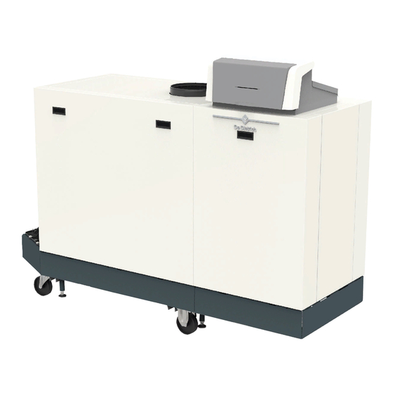
High-efficiency floor-standing gas boiler
S U S T A I N A B L E C O M F O R T ®
ADVANCE
C 340 — C 640
Diematic Evolution
SCB-01
SCB-10
Related Manuals for DeDietrich C 340 Series
Summary of Contents for DeDietrich C 340 Series
-
Page 1
ADVANCE C 340 Installation and User Manual High-efficiency floor-standing gas boiler C 340 — C 640 Diematic Evolution SCB-01 SCB-10 S U S T A I N A B L E C O M F O R T ®… -
Page 2: Table Of Contents
Contents Contents Safety ………………. . 6 General safety instructions .
-
Page 3
Contents Preparation of commissioning …………… . . 55 Checklist before commissioning . -
Page 4
Contents 10 Settings ………………89 10.1 Introduction to parameter codes . -
Page 5
Contents 14.3 Parts list …………….. . . 191 15 Appendix . -
Page 6: Safety
1 Safety Safety General safety instructions 1.1.1 For the installer Danger If you smell gas: 1. Do not use naked flames, do not smoke and do not operate electrical contacts or switches (doorbell, lighting, motor, lift etc.). 2. Shut off the gas supply. 3.
-
Page 7: For The End User
1 Safety 1.1.2 For the end user Danger If you smell gas: 1. Do not use naked flames, do not smoke and do not operate electrical contacts or switches (doorbell, lighting, motor, lift etc.). 2. Shut off the gas supply. 3.
-
Page 8: Recommendations
1 Safety Caution Ensure that the boiler is regularly serviced. Contact a qualified installer or arrange a maintenance contract for the servicing of the boiler. Caution Only genuine spare parts may be used. Important Regularly check for the presence of water and pressure in the heating installation.
-
Page 9
1 Safety Warning Always disconnect the mains supply and close the main gas tap when working on the boiler. Warning Check the entire system for leaks after maintenance and servicing work. Danger For safety reasons, we recommend fitting smoke alarms at suitable places and a CO detector near the appliance. -
Page 10: Liabilities
1 Safety Liabilities 1.3.1 Manufacturer’s liability Our products are manufactured in compliance with the requirements of the various Directives applicable. They are therefore delivered with the marking and any documents necessary. In the interests of the quality of our products, we strive constantly to improve them. We therefore reserve the right to modify the specifications given in this document.
-
Page 11: About This Manual
2 About this manual About this manual Symbols used in the manual This manual contains special instructions, marked with specific symbols. Please pay extra attention when these symbols are used. Danger Risk of dangerous situations that may result in serious personal injury.
-
Page 12: Description Of The Product
3 Description of the product Description of the product Boiler types The following boiler types are available: Tab.1 Boiler types Name Heat exchanger Output size C 340 280 279 kW 5 sections C 340 350 350 kW 6 sections C 340 430 425 kW 7 sections C 340 500…
-
Page 13
3 Description of the product Fig.3 C 640 — back 1 Flow connection 2 Flue gas outlet 3 Return connection 4 Flue gas collector AD-3001554-01 Fig.4 Gas — air unit 1 Gas pressure measuring point 2 Gas supply tube 3 Gas — air connection piece 4 Pressure measurement point 5 Non-return valve 6 Gas filter… -
Page 14: Dimensions And Connections C 340
3 Description of the product Dimensions and connections C 340 Fig.7 Dimensions C 340 AD-3001442-02 C 340 Base length 1833 mm 2142 mm Flue gas outlet centre dimension 1635 mm 1944 mm Total length 1862 mm 2172 mm Casing length 1490 mm 1800 mm Central heating circuit flow…
-
Page 15: Dimensions And Connections C 640
3 Description of the product Dimensions and connections C 640 Fig.8 Dimensions C 640 AD-3001443-02 C 640 1000 1140 1300 Base length 1833 mm 2142 mm Flue gas outlet centre dimension 1582 mm 1892 mm Total length 1862 mm 2172 mm Casing length 1490 mm 1800 mm…
-
Page 16: Accessories And Options
3 Description of the product Fig.9 Generic example R-Bus L-Bus S-Bus AD-3001366-02 Tab.2 Components in the example Item Description Function Control Unit: Control unit The control unit handles all basic functionality of the appli ance. Connection Board: Connection PCB The connection PCB provides easy access to all connectors of the control unit.
-
Page 17
3 Description of the product Important Contact us for more information. Tab.4 Electrical accessories and options available for the C 340 / C 640 boiler Item Description Function Code No. Expansion PCB SCB-13 The SCB-13 provides functionality to connect an external hydraulic valve. AD-3001727-01 PCB AD249 The AD249 provides functionality for an extra… -
Page 18: Preparation Of Installation
4 Preparation of installation Preparation of installation Installation regulations Warning The boiler must be installed by a qualified installer in accordance with local and national regulations. Location requirements Danger It is forbidden to store, even temporarily, combustible products and substances in or near the boiler. Caution The boiler must be installed in a frost-free area.
-
Page 19: Requirements For Water Connections
4 Preparation of installation C 340 C 640 A (mm) B (mm) C (mm) 1862 2962 1000 1032 2172 3272 1140 1032 2172 3272 1300 1032 2172 3272 Requirements for water connections Before installation, check that the connections meet the set requirements.
-
Page 20: Requirements On The Flue Gas Discharge System
4 Preparation of installation Requirements on the flue gas discharge system 4.5.1 Classification Important The installer is responsible ensuring that the right type of flue gas outlet system is used and that the diameter and length are correct. Always use connection materials, roof terminal and/or outside wall terminal supplied by the same manufacturer.
-
Page 21
4 Preparation of installation Tab.8 Type of flue gas connection: C Principle Description Recommended manufactur Room-sealed version Roof terminal and connection material Flue gas discharge via the roof. Air supply opening is in the same pressure zone as the dis Cox Geelen charge (e.g. -
Page 22: Material
4 Preparation of installation Tab.11 Type of flue gas connection: C Principle Description Recommended manufactur Room-sealed version Connection material and roof terminal: Air supply and flue gas discharge duct in shaft or ducted: Concentric. Alukan Air supply from existing duct. Cox Geelen Flue gas discharge via the roof.
-
Page 23: Dimensions Of Flue Gas Outlet Pipe
4 Preparation of installation Warning The coupling and connection methods may vary depending on the manufacturer. It is not permitted to combine pipes, coupling and connection methods from different manufacturers. This also applies to roof feed-throughs and common channels. The materials used must comply with the prevailing regulations and standards.
-
Page 24
4 Preparation of installation Fig.14 Room-ventilated system C 340 L Length of the flue to roof terminal Flue gas outlet connection Tab.15 Maximum length (L) Diameter 150 mm 180 mm 200 mm 250 mm C 340 280 20 m 50 m 50 m 50 m C 340 350… -
Page 25
4 Preparation of installation Fig.17 Room-sealed system C 640 L Combined length of the flue and air supply channel to the roof terminal Flue gas outlet connection Air supply connection Tab.18 Maximum length (L) Diameter 300 mm 350 mm 400 mm C 640 560 100 m 100 m… -
Page 26: Additional Guidelines
4 Preparation of installation 4.5.5 Additional guidelines Air supply filter An air supply filter is separately available. When installing the boiler in a room-ventilated setup (B It is recommended to install the air supply filter if the boiler is installed in a dusty room.
-
Page 27: Water Quality And Water Treatment
4 Preparation of installation Tab.22 PCB connectors Wire cross section Stripping length Tightening torque solid wire: 0.14 – 4.0 mm² (AWG 26 – 12) 8 mm 0.5 N⋅m stranded wire: 0.14 – 2.5 mm² (AWG 26 – 14) stranded wire with ferrule: 0.25 – 2.5 mm² (AWG 24 – 14) Water quality and water treatment The quality of the heating water must comply with the limit values in the table below.
-
Page 28: Connecting Diagrams
4 Preparation of installation Connecting diagrams 4.9.1 Symbols used Tab.24 Explanation of symbols in the hydraulics flow diagram Symbol Explanation Return pipe Flow pipe Mixing valve Pump Domestic hot water Make contact Outdoor temperature sensor Sensor Safety thermostat Room thermostat Plate heat exchanger Safety group Low-loss header…
-
Page 29
4 Preparation of installation Symbol Explanation Shower Heating zone Underfloor heating Underfloor heating manifold Hot-air heater Swimming pool (1) Fitted in domestic hot water storage tank. 7762666 — v.02 — 29092020 C 340 / C 640… -
Page 30: Connection Example — 1 Direct Zone + 1 Mixing Zone + Domestic Hot Water Zone
4 Preparation of installation 4.9.2 Connection example — 1 direct zone + 1 mixing zone + domestic hot water zone Fig.21 1 boiler + 1 direct zone + 1 mixing zone + domestic hot water (DHW) zone AD-4100037-01 L-BUS CB-01 SCB-10 S-BUS Pump…
-
Page 31
4 Preparation of installation Tab.25 On > > Installation Setup > SCB-10 > DHW A > Parameters, counters, signals > Parameters Code Display text Description Range Setting CP022 Zone Function Functionality of the zone 0 = Disable 1 = Direct 2 = Mixing Circuit 3 = Swimming pool 4 = High Temperature… -
Page 32: Connection Example — Primary Buffer Tank + 3 Mixing Zones + Domestic Hot Water Zone
4 Preparation of installation 4.9.3 Connection example — primary buffer tank + 3 mixing zones + domestic hot water zone Fig.22 1 boiler + buffer tank + 3 mixing zones + domestic hot water (DHW) zone AD-4100038-01 L-BUS CB-01 SCB-10 S-BUS Pump 0-10…
-
Page 33
4 Preparation of installation Tab.28 On > > Installation Setup > SCB-10 > CIRCA > Parameters, counters, signals > Parameters Code Display text Description Range Setting CP000 MaxZoneTFlowSetpoint Maximum Flow Temperature setpoint 7 °C — 100 °C zone CP010 Tflow setpoint zone Zone flow temperature setpoint, used 7 °C — 100 °C when the zone is set to a fixed flow… -
Page 34: Connection Example — 1 Mixing Zone + 1 Direct Zone + Swimming Pool + Domestic Hot Water Zone
4 Preparation of installation 4.9.4 Connection example — 1 mixing zone + 1 direct zone + swimming pool + domestic hot water zone Fig.23 1 boiler + 1 mixing zone + 1 direct zone + swimming pool zone + domestic hot water (DHW) zone AD-4100039-01 L-BUS CB-01…
-
Page 35
4 Preparation of installation Tab.29 On > > Installation Setup > SCB-10 > CIRCA > Parameters, counters, signals > Parameters Code Display text Description Range Setting CP020 Zone Function Functionality of the zone 0 = Disable 1 = Direct 2 = Mixing Circuit 3 = Swimming pool 4 = High Temperature 5 = Fan Convector… -
Page 36
4 Preparation of installation Tab.32 On > > Installation Setup > SCB-10 > AUX > Parameters, counters, signals > Parameters Code Display text Description Range Setting CP024 Zone Function Functionality of the zone 0 = Disable 1 = Direct 2 = Mixing Circuit 3 = Swimming pool 4 = High Temperature 5 = Fan Convector… -
Page 37: Connection Example — Low-Loss Header + 3 Mixing Zones + Domestic Hot Water Zone
4 Preparation of installation 4.9.5 Connection example — low-loss header + 3 mixing zones + domestic hot water zone Fig.24 1 boiler + low-loss header + 3 mixing zones + domestic hot water (DHW) zone AD-4100041-01 L-BUS CB-01 SCB-10 S-BUS Pump 0-10 On/off…
-
Page 38
4 Preparation of installation Code Display text Description Range Setting CP020 Zone Function Functionality of the zone 0 Disable 1 Direct 2 Mixing Circuit 3 Swimming pool 4 High Temperature 5 Fan Convector 6 DHW tank 7 Electrical DHW 8 Time Program 9 ProcessHeat 10 DHW Layered 11 DHW Internal tank… -
Page 39
4 Preparation of installation Tab.37 On > > Installation Setup > SCB-10 > Analogue input > Parameters, counters, signals > Adv. Parameters Code Display text Description Range Setting EP036 Sensor input config Sets the general configuration of the 0 = Disabled sensor input 1 = DHW tank 2 = DHW tank top… -
Page 40: Connection Example — 2 Boiler Cascade + Low-Loss Header + 3 Mixing Zones + Domestic Hot Water Zone
4 Preparation of installation 4.9.6 Connection example — 2 boiler cascade + low-loss header + 3 mixing zones + domestic hot water zone Fig.25 2 boiler cascade + low-loss header + 3 mixing zones + domestic hot water (DHW) zone AD-4100044-01 L-BUS CB-01…
-
Page 41
4 Preparation of installation G DHW zone — DHWA (layered calorifier — 2 sensors) A-B S-BUS cable (comes with 2 resistors; one on connector X5 on the SCB-10 PCB and one on connector X10 on the CB-01 PCB from boiler B) Tab.38 Installation Setup >… -
Page 42
4 Preparation of installation Tab.41 Installation Setup > SCB-10 > Cascade management B > Parameters, counters, signals > Parameters Code Display text Description Range Setting AP083 Enable master func Enable the master functionality of this 0 = No device on the S-Bus for system control 1 = Yes Tab.42 Installation Setup >… -
Page 43: Installation
5 Installation Installation Positioning the boiler Refer to the lifting instructions document on how to unpack and transport the boiler to the location. Fig.26 Place the boiler 1. Manoeuvre the boiler to the exact location. 2. Unscrew the levelling feet until they stand firmly on the floor. AD-3001416-02 Fig.27 Open the casing…
-
Page 44: Mounting An Outdoor Temperature Sensor
5 Installation Mounting an outdoor temperature sensor 5.2.1 Positions to be avoided Avoid placing the outside sensor in a position with the following characteristics: Masked by part of the building (balcony, roof, etc.). Close to a disruptive heat source (sun, chimney, ventilation grid, etc.). Fig.29 MW-3000014-2 5.2.2…
-
Page 45: Fitting The Outdoor Sensor
5 Installation 5.2.3 Fitting the outdoor sensor Fig.31 Plugs diameter 4 mm/drill diameter 6 mm 1. Choose a recommended location for the outdoor sensor. 2. Put the 2 plugs in place, delivered with the sensor. 3. Secure the sensor using the screws provided (diameter 4 mm). 4.
-
Page 46: Connecting The Gas Pipe
5 Installation Fig.33 Connecting the condensate 1. Remove the protective cap from the condensate connection. discharge pipe Caution Water from the factory test may come out. 2. Fit the siphon by screwing the swivel nut onto the connection. 3. Fit a plastic drain pipe of Ø 32 mm or larger to the siphon, terminating in the drain.
-
Page 47: Electrical Connections
5 Installation Fig.36 Fit the air inlet pipe to the boiler 3. Fit the air supply pipe to the boiler. 4. Fit the subsequent air supply pipes in accordance with the manufacturer’s instructions. Caution The pipes must not be resting on the boiler. Fit the horizontal parts sloping down towards the air supply outlet.
-
Page 48
5 Installation Connecting the system pump Fig.39 System pump 1. Connect a system pump to the Pump terminals of the connector. Important The maximum power consumption is 300 VA. The function of the system pump can be changed using parameters PP015, PP016 and PP018. -
Page 49: The Scb-01 Expansion Pcb
5 Installation Fig.44 Blocking input The boiler has a blocking input. A potential-free contact can be connected to the BL terminals of the connector. If the contact is opened, the boiler will be blocked. Change the function of the input using parameter AP001. This parameter has the following 3 configuration options: Complete blocking: no frost protection with the outdoor sensor and no boiler frost protection (pump does not start and burner does not start)
-
Page 50: The Scb-10 Expansion Pcb
5 Installation Connecting 0–10 V output Fig.48 0–10 V output connector The 0-10 contact can be used to connect a PWM system pump. The speed of the pump is modulated based on the signal received from the 0-10 boiler. Depending on the make and type of pump, the pump can be controlled by a 0–10 V or a PWM signal.
-
Page 51
5 Installation 13 Domestic hot water sensor 19 Coding wheel, selects the generator number in the 14 Flow sensor — circuit C cascade in Mod-Bus 15 Flow sensor — circuit B 20 S-BUS connector 16 Flow sensor — circuit A 21 End connector for L-BUS connection 17 Impressed current anode 22 L-BUS connector… -
Page 52
5 Installation The 0–10 V signal controls the boiler flow temperature in a linear way. This control modulates on the basis of flow temperature. The output varies between the minimum and maximum value on the basis of the flow temperature set point calculated by the controller. Fig.54 Telephone connector Connect the telephone connector as follows:… -
Page 53: Connecting The Power Cable
5 Installation Fig.59 Anode connector Connect the anode as follows: + Connection on the calorifier tank — Connection on the anode + TA — Caution If the calorifier tank does not have a TAS anode, connect the simulation anode (= accessory) AD-4000005-02 5.8.5 Connecting the power cable…
-
Page 54: Cable Routing In The Control Box Front Part
5 Installation 5.8.6 Cable routing in the control box front part Caution Make sure the cable routing matches the illustration when closing the control box. Fig.61 Cable routing in the control box front part AD-3001768-01 C 340 / C 640 7762666 — v.02 — 29092020…
-
Page 55: Preparation Of Commissioning
6 Preparation of commissioning Preparation of commissioning Checklist before commissioning 6.1.1 Filling the installation The recommended water pressure is between 1.5 bar and 2.0 bar. Proceed as follows to fill the installation: 1. Disconnect the boiler from the power supply. Fig.62 Filling and drain valve location 2.
-
Page 56: Control Panel Description
6 Preparation of commissioning Control panel description 6.2.1 Control panel components Fig.65 Control panel components 1 Rotary knob to select a tile, menu or setting 2 Confirm button to confirm the selection 3 Back button Short button press: Return to the previous level or previous menu Long button press: Return to home screen 4 Menu button…
-
Page 57: Meaning Of The Icons In The Display
6 Preparation of commissioning Tab.45 Available menus for the installer Description Icon Installation Setup Commissioning Menu Advanced Service Menu Error History System Settings Version Information 6.2.4 Meaning of the icons in the display Tab.46 Icons Icon Description User menu: user-level parameters can be configured. Installer menu: installer-level parameter can be configured.
-
Page 58
6 Preparation of commissioning Tab.47 Icons — Zones Icon Description All zones (groups) icon. Living room icon. Kitchen icon. Bedroom icon. Study icon. Cellar icon. C 340 / C 640 7762666 — v.02 — 29092020… -
Page 59: Commissioning
7 Commissioning Commissioning Commissioning procedure Warning Commissioning must be done by a qualified installer. If adapting to another gas type, the gas valve unit must be adjusted before switching on the boiler. 1. Open the main gas valve. 2. Open the appliance gas valve. 3.
-
Page 60: Adjusting To A Different Gas Type
7 Commissioning 7.2.2 Adjusting to a different gas type Warning Only a qualified installer may carry out the following operations. Important If the boiler is adapted to another gas type, this must be stated on the sticker supplied. This sticker must be affixed next to the data plate.
-
Page 61: Checking And Setting The Gas/Air Ratio
7 Commissioning Code Displayed text Description 1000 1140 1300 GP008 Fan RPM Min Minimum fan speed during Central 1900 1850 1300 1250 1400 1350 Heating + Domestic Hot Water mode GP009 Fan RPM Start Fan speed at appliance start 2500 2500 1300 1400…
-
Page 62
7 Commissioning Values at full load for G20 (H gas) C 640 700 4.3 – 4.8 C 640 860 4.3 – 4.8 C 640 1000 4.3 – 4.8 C 640 1140 4.3 – 4.8 C 640 1300 4.3 – 4.8 (1) Nominal value Tab.53 Checking/setting values for O… -
Page 63
7 Commissioning Performing the low load test 1. If the full load test is still running, press the button to change the load test mode. 2. If the full load test was finished, select the tile [ ] to restart the chimney sweep menu. -
Page 64: Final Instructions
7 Commissioning 4. If the measured value is outside of the values given in the table, correct the gas/air ratio. Fig.73 Adjusting screw B 5. Use the adjustment screw B to set the percentage of O for the gas type being used to the nominal value. Increasing the gas flow, will decrease O .
-
Page 65: Saving The Commissioning Settings
7 Commissioning 7.3.1 Saving the commissioning settings You can save all current settings on the control panel. These settings can be restored if necessary, for example after replacement of the control unit. 1. Press the button. 2. Use the rotary knob to select Advanced Service Menu. 3.
-
Page 66: User Instructions
8 User instructions User instructions Accessing the user level menus The tiles on the home screen provide quick access for the user to the corresponding menus. Fig.75 Menu selection 1. Use the rotary knob to select the required menu. 22/02/2018 11:20 Home Screen ..
-
Page 67: Activating Holiday Programs For All Zones
8 User instructions Activating holiday programs for all zones If you go on holiday, the room temperature and domestic hot water temperature can be reduced to save energy. With the following procedure you can activate the holiday mode for all zones and domestic hot water temperature.
-
Page 68: Changing The Room Temperature Of A Zone
8 User instructions Menu Function Holiday Mode Set the start and end date of your holiday and the reduced temperature for this zone Zone friendly Name Create or change the name of the heating circuit Icon display zone Select the icon of the heating circuit OperatingZoneMode Read the current operating mode of the heating circuit Changing the room temperature of a zone…
-
Page 69: Changing The Operating Mode Of A Zone
8 User instructions Fig.79 Confirm sign 8. Select the sign on the screen when the name is complete. 9. Press the button to confirm the selection. 11:20 ….: ….10. Use the rotary knob to select Icon display zone. 11.
-
Page 70
8 User instructions 9. Use the rotary knob to select the weekday you want to modify. Fig.80 Weekday A Weekday B Overview of scheduled activities C List of actions 11:20 …………10. Perform the following actions, if necessary: ..:.. -
Page 71: Changing The Heating Activity Temperatures
8 User instructions Activating a timer program In order to use a timer program, it is necessary to activate the operating mode Scheduling. This activation is done separately for each zone. 1. Select the tile of the zone you want to change. 2.
-
Page 72: Reading The Installer’s Name And Phone Number
8 User instructions 2. Press the button to confirm the selection. 3. Use the rotary knob to select System Settings 4. Press the button to confirm the selection. 5. Perform one of the operations described in the table below: Tab.62 Display settings System Settings menu Settings…
-
Page 73: Installer Instructions
9 Installer instructions Installer instructions Accessing the installer level Some parameters that may affect the operation of the boiler are protected by an access code. Only the installer is allowed to modify these parameters. 1. Select the tile [ 2. Press the button to confirm the selection.
-
Page 74: Setting The Installer Details
9 Installer instructions Tab.65 Configuring a zone or function of CU-GH13 or SCB-10 Parameters, counters, signals Description Parameters Set the parameters at installer level Counters Read the counters at installer level Signals Read the signals at installer level Adv. Parameters Set the parameters at advanced installer level Adv.
-
Page 75: Setting The Boiler Parameters When Scb-10 Is Fitted
9 Installer instructions Caution Changing the factory settings may adversely affect the operation of the boiler. 9.2.3 Setting the boiler parameters when SCB-10 is fitted When the boiler is fitted with the SCB-10 the following boiler CU-GH13 parameter(s) at installer level must be checked and adjusted, if necessary: 1.
-
Page 76
9 Installer instructions DHW1 with parameter CP022 set as Disable CIRCC1 with parameter CP023 set as Disable AUX1 with parameter CP024 set as Disable To configure your specific installation, make sure to check and adjust the parameter settings for the selected zones. The zone function table shows which parameter settings are available for which zones. -
Page 77: 0-10 Volt Control With Expansion Pcb
9 Installer instructions Zone setting Explanation 10 = DHW Layered Setting to manage domestic hot water with 2 sensors, a tank top sensor (Tsyst 1 or 2) triggers the load and the bottom sensor of the tank (Tdhw) triggers the stop of the charge. 11 = DHW Internal tank Setting to manage domestic hot water for boilers with internal tank.
-
Page 78: Setting The Heating Curve
9 Installer instructions Hardware configuration Install the hardware components according following instructions: 1. Place the 0-10 volts device at the appropriate position according packed instructions. Electrical connections Fig.87 Connecting 0-10 volts with 1. Connect the wires to the 0-10 volts device. expansion PCB 2.
-
Page 79: Status Output On Expansion Pcb
9 Installer instructions 9.2.7 Status output on expansion PCB The appliance can output status information via a status contact. You can use this output to turn on a signal light or relay when the appliance is in a locking or blocking status, for example. Two types of status contacts exist: Fig.89 types of status contacts, in rest…
-
Page 80: Commissioning The Installation
9 Installer instructions Tab.73 Parameter settings Code Display text Advice EP018 Status relay func. Configure the function of the status contacts. 0 = No Action : The status contact (C-Nc) will do nothing. EP019 1 = Alarm : The status contact (C-No) will close when there is an error. 2 = Alarm Inverted : The status contact (C-No) is closed when there is no error.
-
Page 81: Saving The Commissioning Settings
9 Installer instructions Tab.75 Load test settings Load Test menu Settings Func. test status Select the load test to start the test. System Flow Temp Read the central heating flow temperature T return Read the central heating return temperature Actual fan RPM Read the actual fan speed Actual flame current Read the actual flame current…
-
Page 82: Maintaining The Installation
9 Installer instructions Maintaining the installation 9.4.1 Viewing the service notification When a service notification appears on the display, you can view the details of the notification. 1. Select the tile [ 2. Press the button to confirm the selection. The View Service Notification menu opens.
-
Page 83: Changing The Domestic Hot Water Temperature Temporarily
9 Installer instructions 4. Use the rotary knob to select the appliance, control board or any other device you want to view. Fig.96 Version information A Select the appliance, control board or device B List of information 11:20 ….: ..
-
Page 84: Carrying Out An Auto Detect
9 Installer instructions 9. Press the button to confirm the selection. 10. Use the rotary knob to select and change the CN2 setting. 11. Press the button to confirm the selection. 12. Use the rotary knob to select Confirm to confirm the changed numbers.
-
Page 85: Changing The Δt Setting
9 Installer instructions 9.6.2 Changing the ΔT setting The ΔT is factory set to 25 °C. It can be increased by a De Dietrich service technician. Contact De Dietrich for more information. Important When increasing the ΔT, the control unit limits the flow temperature to a maximum of 80 °C.
-
Page 86
9 Installer instructions Fig.99 Cascade numbering Master appliance is number 1 The first slave appliance is number 3 (number 2 does not exist). The second slave appliance is number 4; and so on. There are two options for cascade control management: Adding supplementary appliances successively (traditional control) Adding supplementary appliances simultaneously (parallel control) AD-3000964-01… -
Page 87
9 Installer instructions Fig.102 Hardware configuration cascade AD-3001544-01 A Master appliance B Slave appliance Electrical connections Fig.103 Master — slave connections L-BUS X1 1 S-BUS S-BUS S-BUS S-BUS 0-10V S out RU.C RU.B RU.A +TA- S.SYST.1 S.SYST.2 S.DHW S.DEP.C S.DEP.B S.DEP.A AD-3001545-01 A SCB-10 (mounted in master appliance) C Terminator connector… -
Page 88
9 Installer instructions Code Display text Advice NP011 CascadeTypeAlgo Select which type of cascade management is requested, temperature (0) or power (1) based. NP012 CascPowerRiseTime Set the time available for reaching the desired temperature. Typically set this value to 1. This value will be multiplied by 10. NP013 CascForceStop Pprim Select to enable (1) or disable (2) the cascade primary pump. -
Page 89: 10 Settings
10 Settings 10 Settings 10.1 Introduction to parameter codes Fig.104 Code on a Diematic Evolution The controls platform makes use of an advanced system to categorise parameters, measurements and counters. Knowing the logic behind these 00:12 ……codes, makes it easier to identify them.
-
Page 90
10 Settings Tab.79 Factory settings at basic installer level Code Display text Description Adjustment range Subme AP016 CH function Enable central heating 0 = Off heat demand processing 1 = On fired ap pliance AP017 DHW func Enable domestic hot water 0 = Off tion on heat demand processing… -
Page 91
10 Settings Code Display text Description Adjustment range Subme CP660 Icon display Choice icon to display this 0 = None Direct zone zone 1 = All zone 2 = Bedroom 3 = Livingroom 4 = Study 5 = Outdoor 6 = Kitchen 7 = Basement 8 = Swimming Pool 9 = DHW Tank… -
Page 92
10 Settings Code Display text Description Adjustment range Subme AP010 Service noti Select the type of service 0 = None fication notification 1 = Custom notifi fired ap cation pliance 2 = ABC notifica tion AP011 Service Hours powered to raise a 100 — 25500 Hours 8750 8750 8750 8750 8750 8750 hours mains… -
Page 93
10 Settings Code Display text Description Adjustment range Subme CP060 RoomT. Wished room zone tem 5 — 20 °C Direct Holiday perature on holiday period zone CP070 MaxRedu Max Room Temperature 5 — 30 °C Direct ce limit of the circuit in re zone dRoomT.Li duced mode, that allows… -
Page 94
10 Settings Code Display text Description Adjustment range Subme GP008 Fan RPM Minimum fan speed during 900 — 8500 Rpm 1400 1550 950 1050 1100 1050 Central Heating + Domes fired ap tic Hot Water mode pliance Pneu matic GP009 Fan RPM Fan speed at appliance 900 — 5000 Rpm… -
Page 95
10 Settings Code Display text Description Adjustment range Subme CP010 Tflow set Zone flow temperature 7 — 100 °C Direct point zone setpoint, used when the zone zone is set to a fixed flow setpoint. CP290 ConfigZone Configuration of Zone 0 = Zone output Zone PumpOut… -
Page 96: Cu-Gh13 Control Unit Settings — C 640
10 Settings Code Display text Description Adjustment range Subme PP007 Min anti-cy Minimum heat generator 1 — 20 Min cle time holding time that can be fired ap reached after a stop pliance PP012 Stabilization Stabilization time after 0 — 180 Sec time heat generator start for fired ap…
-
Page 97
10 Settings Code Display text Description Adjustment range Subme 1000 1140 1300 CP200 Manu Zo Manually setting the room 5 — 30 °C Direct neRoom temperature setpoint of zone TempSet the zone CP320 Operating Operating mode of the 0 = Scheduling Direct ZoneMode zone… -
Page 98
10 Settings Tab.87 Factory settings at installer level Code Display text Description Adjustment range Subme 1000 1140 1300 AP001 BL function BL input function selection 1 = Full blocking 2 = Partial blocking fired ap 3 = User reset lock pliance 4 = Backup re… -
Page 99
10 Settings Code Display text Description Adjustment range Subme 1000 1140 1300 AP098 BL1 contact BL1 input contact configu 0 = Open config. ration 1 = Closed fired ap 2 = Off pliance CP000 MaxZoneT Maximum Flow Tempera 7 — 100 °C Direct FlowSet… -
Page 100
10 Settings Code Display text Description Adjustment range Subme 1000 1140 1300 CP640 OTH Logi Opentherm Logic level 0 = Open Direct cLev con contact of the zone 1 = Closed zone tact 2 = Off CP730 Zone Heat Selection of heat up speed 0 = Extra Slow Direct up speed… -
Page 101
10 Settings Tab.88 Navigation for advanced installer level Level Menu path Advanced installer > Installation Setup > CU-GH > Submenu > Parameters, counters, signals > Adv. Parameters (1) See the column «Submenu» in the following table for the correct navigation. The parameters are grouped in specific functionalities. Tab.89 Factory settings at advanced installer level Code… -
Page 102: Scb-01 Expansion Pcb Settings
10 Settings Code Display text Description Adjustment range Subme 1000 1140 1300 DP020 Postrun Post run time of the DHW 0 — 99 Sec pump/3 way valve after fired ap pump/3wv DHW production pliance DP140 DHW load DHW load type (0 : Combi, 0 = Combi type 1 : Solo)
-
Page 103: Scb-10 Expansion Pcb Settings
10 Settings Tab.91 Factory settings at installer level Code Display text Description Range Subme Default setting EP018 Status relay func. Status relay function 0 = No Action Status 1 = Alarm informati 2 = Alarm Inverted 3 = Burning 4 = Not burning 5 = Reserved 6 = Reserved 7 = Service request…
-
Page 104
10 Settings Tab.93 Factory settings at basic installer level Code Display text Description Range Submenu Default setting AP074 Force summer The heating is stopped. Hot water is 0 = Off Outdoor mode maintained. Force Summer Mode 1 = On temperature AP077 Max. -
Page 105
10 Settings Code Display text Description Range Submenu Default setting CP146 RoomCoolTempS Setpoint of the room cooling 20 °C — 30 °C CIRCB 1 CP147 etpoint temperature of the zone CP148 CP149 CP150 CP151 CP152 RoomCoolTempS Setpoint of the room cooling 20 °C — 30 °C DHW 1 CP153… -
Page 106
10 Settings Code Display text Description Range Submenu Default setting CP570 ZoneTimeProg Time Program of the zone selected 0 = Schedule 1 CIRCA 1 CP571 Select by the user 1 = Schedule 2 CIRCB 1 CP572 2 = Schedule 3 DHW 1 CP573 3 = Cooling… -
Page 107
10 Settings Code Display text Description Range Submenu Default setting AP091 Outside Sens. Type of outside sensor connection to 0 = Auto Outdoor Source be used 1 = Wired sensor temperature 2 = Wireless sensor 3 = Internet measured 4 = None BP001 Type Buffer Tank Type of buffer tank… -
Page 108
10 Settings Code Display text Description Range Submenu Default setting CP020 Zone Function Functionality of the zone 0 = Disable CIRCA 1 CP021 1 = Direct CIRCB 1 CP022 2 = Mixing Circuit DHW 1 CP023 3 = Swimming pool CIRCC 1 CP024 4 = High Temperature… -
Page 109
10 Settings Code Display text Description Range Submenu Default setting CP270 CoolMixTflowZon Mixing flow temperature setpoint 11 °C — 23 °C CIRCA 1 CP271 eSet cooling of the zone CIRCB 1 CP272 DHW 1 CP273 CIRCC 1 CP274 AUX 1 CP280 FanCoolTflowZon Fan flow setpoint cooling of the zone… -
Page 110
10 Settings Code Display text Description Range Submenu Default setting CP480 ScreedStartTemp Setting of the start temperature of the 20 °C — 50 °C CIRCA 1 CP481 screed drying program of the zone CIRCB 1 CP482 DHW 1 CP483 CIRCC 1 CP484 AUX 1 CP490… -
Page 111
10 Settings Code Display text Description Range Submenu Default setting CP700 DHW Cal Offset Offset for calorifier sensor per zone 0 °C — 30 °C CIRCA 1 CP701 zone CIRCB 1 CP702 DHW 1 CP703 CIRCC 1 CP704 AUX 1 CP710 Zone Increase primary temperature… -
Page 112
10 Settings Code Display text Description Range Submenu Default setting EP035 Max Setp Volt Sets the maximum set point voltage 0 V — 10 V 0-10 volt 0-10V for 0 — 10 volts input EP046 Digital input Sets the general configuration of the 0 = Stop heating + DHW Digital Input config… -
Page 113
10 Settings Tab.97 Factory settings at advanced installer level Code Display text Description Range Submenu Default setting AP111 Can line length Can line length 0 = < 3m Mandatory AP112 1 = < 80m bus master 2 = < 500m Cascade management CP290… -
Page 114: List Of Measured Values
10 Settings Code Display text Description Range Submenu Default setting CP800 Commercial Dhw Select the requested heating mode 0 = Preheat CIRCA 1 CP801 Mode for commercial domestical hot water 1 = Heating CIRCB 1 CP802 tank DHW 1 CP803 CIRCC 1 CP804 AUX 1…
-
Page 115
10 Settings Code Display text Description Range Submenu AC005 CH Energy Con Energy consumed for central heating 0 — 4294967295 kWh Producer Ge sumed neric Gas fired ap pliance AC006 DHW energy con Energy consumed for domestic hot water 0 — 4294967295 kWh Producer Ge… -
Page 116: Scb-01 Expansion Pcb Counters
10 Settings 10.4.2 SCB-01 expansion PCB counters Tab.104 Navigation for basic installer level Level Menu path Basic installer > Installation Setup > SCB-01 > Submenu > Parameters, counters, signals > Counters (1) See the column «Submenu» in the following table for the correct navigation. The counters are grouped in specific functionalities. Tab.105 Counters at basic installer level Code Display text…
-
Page 117
10 Settings Code Display text Description Range Submenu CC002 Zone Pump Run Numbers of pump operating hours of the 0 — 4294967294 Direct zone Hours zone Mixed zone Swimming pool High temp. zone Fan convector zone DHW tank Electrical DHW tank Process heat DHW layered tank… -
Page 118
10 Settings Code Display text Description Range Submenu CC005 Zone Pump Run Numbers of pump operating hours of the 0 — 4294967294 Direct zone Hours zone Mixed zone Swimming pool High temp. zone Fan convector zone DHW tank Electrical DHW tank Process heat DHW layered tank… -
Page 119
10 Settings Code Display text Description Range Submenu CC012 Zone Nbr Pump Numbers of times the pump of the zone 0 — 4294967294 Direct zone Starts has started Mixed zone Swimming pool High temp. zone Fan convector zone DHW tank Electrical DHW tank Process heat… -
Page 120: Control Unit Signals
10 Settings 10.4.4 Control unit signals Tab.108 Navigation for basic installer level Level Menu path Basic installer > Installation Setup > CU-GH13 > Submenu > Parameters, counters, signals > Signals (1) See the column «Submenu» in the following table for the correct navigation. The signals are grouped in specific functionalities. Tab.109 Signals at basic installer level Code Display text…
-
Page 121
10 Settings Code Display text Description Range Submenu CM120 ZoneCurrentMode Zone Current Mode 0 = Scheduling Direct zone 1 = Manual 2 = Antifrost 3 = Temporary CM130 ZoneCurrent activi Current activity of the zone 0 = Anti frost Direct zone 1 = Reduced 2 = Comfort 3 = Anti legionella… -
Page 122: Scb-01 Expansion Pcb Signals
10 Settings Tab.113 Signals at advanced installer level Code Display text Description Range Submenu AM001 DHW active Is the appliance currently in domestic hot 0 = Off Gas fired ap water production mode? 1 = On pliance AM011 Service required? Is service currently required? 0 = No Gas fired ap…
-
Page 123: Scb-10 Expansion Pcb Signals
10 Settings Code Display text Description Range Submenu AM015 Pump running? Is the pump running? 0 = Inactive 0-10 volt or 1 = Active PWM out GM011 Power setpoint Power setpoint in % of maximum 0 % — 655.35 % 0-10 volt or PWM out Tab.116 Navigation for installer level…
-
Page 124
10 Settings Code Display text Description Range Submenu CM031 Zone Measure of the room temperature of the 0 °C — 50 °C Direct zone RoomTemperature zone Mixed zone High temp. zone Fan convector zone CM032 Zone Measure of the room temperature of the 0 °C — 50 °C Direct zone RoomTemperature… -
Page 125
10 Settings Code Display text Description Range Submenu CM043 Zone Tflow /DHW Measure Zone Flow Temperature or -10 °C — 140 °C Mixed zone temp DHW temperature Swimming pool DHW tank Electrical DHW tank Process heat DHW layered tank Commercial Tank CM044 Zone Tflow /DHW… -
Page 126
10 Settings Code Display text Description Range Submenu CM062 ZonePumpSpeed Current Pump speed of zone 0 % — 100 % Direct zone Mixed zone Swimming pool High temp. zone Fan convector zone DHW tank Electrical DHW tank Process heat DHW layered tank Commercial Tank… -
Page 127
10 Settings Code Display text Description Range Submenu CM070 Zone Tflow Current Flow temperature setpoint of 0 °C — 150 °C Direct zone Setpoint zone Mixed zone Swimming pool High temp. zone Fan convector zone DHW tank Electrical DHW tank Process heat DHW layered tank… -
Page 128
10 Settings Code Display text Description Range Submenu CM073 Zone Tflow Current Flow temperature setpoint of 0 °C — 150 °C Direct zone Setpoint zone Mixed zone Swimming pool High temp. zone Fan convector zone DHW tank Electrical DHW tank Process heat DHW layered tank… -
Page 129
10 Settings Code Display text Description Range Submenu CM121 ZoneCurrentMode Zone Current Mode 0 = Scheduling Direct zone 1 = Manual Mixed zone 2 = Antifrost Swimming 3 = Temporary pool High temp. zone Fan convector zone DHW tank Electrical DHW tank DHW layered tank… -
Page 130
10 Settings Code Display text Description Range Submenu CM124 ZoneCurrentMode Zone Current Mode 0 = Scheduling Direct zone 1 = Manual Mixed zone 2 = Antifrost Swimming 3 = Temporary pool High temp. zone Fan convector zone DHW tank Electrical DHW tank DHW layered tank… -
Page 131
10 Settings Code Display text Description Range Submenu CM132 ZoneCurrent Current activity of the zone 0 = Anti frost Direct zone activity 1 = Reduced Mixed zone 2 = Comfort Swimming 3 = Anti legionella pool High temp. zone Fan convector zone DHW tank Electrical… -
Page 132
10 Settings Code Display text Description Range Submenu CM190 Zone Troom Wished room temperature setpoint of the 0 °C — 50 °C Direct zone setpoint zone Mixed zone High temp. zone Fan convector zone CM191 Zone Troom Wished room temperature setpoint of the 0 °C — 50 °C Direct zone setpoint… -
Page 133
10 Settings Code Display text Description Range Submenu CM204 ZoneCurrentHeatM Displaying current operating mode of the 0 = Standby Direct zone zone 1 = Heating Mixed zone 2 = Cooling Swimming pool High temp. zone Fan convector zone CM210 ZoneTout temp Current outdoor temperature of the zone -70 °C — 70 °C Direct zone Mixed zone… -
Page 134
10 Settings Tab.121 Signals at installer level Code Display text Description Range Submenu AM200 Status contact 1 Status of status contact 1. The meaning 0 = Off Status is dependant on the current function 1 = On information setting. BM001 Meas Btank temp Measured buffer tank temperature -1 °C — 150 °C… -
Page 135
10 Settings Code Display text Description Range Submenu CM164 Zone Mod Presense of modulating heat demand 0 = No Direct zone HeatDemand per zone 1 = Yes Mixed zone High temp. zone Fan convector zone Electrical DHW tank DHW layered tank CM290 ZoneSecSwimPool… -
Page 136
10 Settings Code Display text Description Range Submenu NM001 CascSystemTF Cascade system flow temperature -10 °C — 120 °C Producer Manager Cascade management Producer<>C onsumer NM022 CascNbStageAvail Number of stage available on the 0 — 255 Cascade able Cascade management NM023 CascNbStageRequ Number of stage required on the… -
Page 137
10 Settings Code Display text Description Range Submenu CM023 Zone 3WV opening Mixing valve opening status of zone 0 = No Mixed zone 1 = Yes Swimming pool Electrical DHW tank CM024 Zone 3WV opening Mixing valve opening status of zone 0 = No Mixed zone 1 = Yes… -
Page 138
10 Settings Code Display text Description Range Submenu CM052 Status Pump zone Status of the Pump of zone 0 = No Direct zone 1 = Yes Mixed zone Swimming pool High temp. zone Fan convector zone DHW tank Electrical DHW tank Zone time program Process heat… -
Page 139
10 Settings Code Display text Description Range Submenu CM110 ZoneTRoomUnit Room Unit temperature setpoint of zone 0 °C — 50 °C Direct zone setp Mixed zone High temp. zone Fan convector zone CM111 ZoneTRoomUnit Room Unit temperature setpoint of zone 0 °C — 50 °C Direct zone setp… -
Page 140
10 Settings Code Display text Description Range Submenu CM142 ZoneOTContr OpenTherm controller is connected to 0 = No Direct zone present the zone 1 = Yes Mixed zone Swimming pool High temp. zone Fan convector zone Electrical DHW tank DHW layered tank CM143 ZoneOTContr… -
Page 141
10 Settings Code Display text Description Range Submenu CM152 ZoneState State of On Off heat demand per zone 0 = No Direct zone Heatdemand 1 = Yes Mixed zone Swimming pool High temp. zone Fan convector zone Electrical DHW tank DHW layered tank CM153… -
Page 142
10 Settings Code Display text Description Range Submenu CM181 Zone RU present Presense of Room Unit in this zone 0 = No Direct zone 1 = Yes Mixed zone Swimming pool High temp. zone Fan convector zone DHW tank Electrical DHW tank Process heat DHW layered… -
Page 143
10 Settings Code Display text Description Range Submenu CM184 Zone RU present Presense of Room Unit in this zone 0 = No Direct zone 1 = Yes Mixed zone Swimming pool High temp. zone Fan convector zone DHW tank Electrical DHW tank Process heat DHW layered… -
Page 144: Status And Sub-Status
10 Settings Code Display text Description Range Submenu CM282 ZoneRTC Internal room temperature setpoint 0 °C — 100 °C Direct zone TcalcRoomStp calculated by the room temperature Mixed zone controller of the zone High temp. zone Fan convector zone CM283 ZoneRTC Internal room temperature setpoint 0 °C — 100 °C…
-
Page 145
10 Settings Code Display text Explanation Generator stop The appliance has stopped. Pump Post Run The pump is active after the appliance stopped. Controlled Stop The appliance does not start because the starting conditions are not met. Blocking Mode A blocking mode is active. Locking Mode A locking mode is active. -
Page 146
10 Settings Code Display text Explanation LimitedPwrOnTflueGas The power of the appliance is decreased to lower the flue gas tem perature. Reduced Set Point The desired flow temperature is reduced to protect the heat exchang PumpPostRunning The pump is active after the appliance stopped in order to bring the remaining heat into the system. -
Page 147: 11 Maintenance
11 Maintenance 11 Maintenance 11.1 Maintenance regulations Important The boiler must be maintained by a qualified installer in accordance with local and national regulations. An annual inspection is mandatory. Perform the standard checking and maintenance procedures once a year. Perform the specific maintenance procedures if necessary. Important Adjust the frequency of inspection and service to the conditions of use.
-
Page 148: Preparation
11 Maintenance The boiler service manual for the specific maintenance work. This manual can be found on the website. 11.3.1 Preparation Carry out the following steps before commencing inspection and maintenance activities: 1. Set the boiler to full load until the return temperature is around 65°C, to dry the heat exchanger on the flue gas side.
-
Page 149: Checking And Cleaning The Air Supply Hose
11 Maintenance Fig.110 Gas control valve measuring points 1. Set the boiler to full load. 2. Measure the gas inlet pressure via the measuring point P1 on the gas pipe. This gas inlet pressure should be at least 17 mbar. 3.
-
Page 150: Checking The Air Box
11 Maintenance 11.3.6 Checking the air box Fig.113 Air box 1. Check the air box for soiling. 2. Clean the dirty air box using a vacuum cleaner. Do this from the connection opening for the air supply hose. Important If the air box is dirty, the following components must also be dismantled and blown clean: Non-return valve Venturi…
-
Page 151: Checking The Gas Leakage Monitoring (Vps)
11 Maintenance Fig.115 Negative (-) side of the air pressure 10. Remove the syringe hose from the + side of the air pressure differential switch differential switch and reconnect the original hose. 11. Disconnect the silicon hose from the — side (P2) of the air pressure differential switch.
-
Page 152: Checking The Minimum Gas Pressure Switch (Gps)
11 Maintenance Fig.118 Checking the VPS for leaks 7. Take a T piece and connect it as follows: 7.1. Connect one end of the T piece to the hose from measuring point 3. 7.2. Connect one end of the T piece to a large plastic syringe. 7.3.
-
Page 153: Specific Maintenance Work
11 Maintenance Fig.122 Connect the pressure gauge 2. Open the screw in measuring point 2 of the gas control valve. 3. Connect a pressure gauge to measuring point 2 of the gas control valve. 5/6/7/8/9 4. Switch on the boiler. 5.
-
Page 154: Cleaning The Fan, Non-Return Valve And Venturi
11 Maintenance 11.4.1 Cleaning the fan, non-return valve and venturi Fig.125 Disassembling the fan unit 1. Push back the safety slides on both sides of the power plug to unlock 2. Remove the electrical connections from the fan. 3. Unscrew the bolts from the extension piece under the fan. Support the gas control valve, using a block of wood for example.
-
Page 155: Cleaning The Gas Filter — 5-9 Sections Boiler
11 Maintenance Fig.128 Replacing the ionisation/ignition 1. Unscrew the two screws on the middle top casing. electrode 2. Remove the middle top casing. 3. Remove the plug of the electrode from the ignition transformer. Important The ignition cable is fixed to the electrode and may not be removed.
-
Page 156: Cleaning The Burner
11 Maintenance Fig.132 Inspecting and cleaning the gas 4. Inspect the gas filter. filter 4.1. Replace the gas filter if necessary. 4.2. Clean the gas filter without the use of liquids (shake it or carefully blow it clean) if it does not need to be replaced. 5.
-
Page 157: Cleaning The Heat Exchanger
11 Maintenance 11.4.6 Cleaning the heat exchanger Fig.137 Removing the inspection hatch 1. Unscrew the nuts from the inspection hatch on the heat exchanger. 2. Carefully remove the inspection hatch, the insulation cloth and the silicon insulation cord from the heat exchanger. Caution The insulation cloth may stick to the heat exchanger.
-
Page 158: Cleaning The Siphon
11 Maintenance 11.4.8 Cleaning the siphon Fig.140 Cleaning the siphon 1. Remove the siphon. 2. Clean the siphon with water. 3. Put the siphon back in place. AD-3001605-01 Fig.141 Filling the siphon 4. Fill the siphon with water up to the mark via the condensate collector. Danger The siphon must always be sufficiently filled with water.
-
Page 159: Finalising Work
11 Maintenance Fig.144 Fitting the electrical connections 9. Connect the electrical connections to the fan. and air supply hose 10. Lock the fan power plug with the safety slides. 11. Mount the air supply hose to the air box. AD-3001590-01 11.5 Finalising work 1.
-
Page 160: 12 Troubleshooting
12 Troubleshooting 12 Troubleshooting 12.1 Error codes The boiler is fitted with an electronic regulation and control unit. The heart of the control is a microprocessor, which controls and also protects the boiler. In the event of an error, a corresponding code is displayed. Tab.128 Error codes are displayed at three different levels Code Type…
-
Page 161
12 Troubleshooting Code Display text Description Solution A.00.34 TOutside Missing Outside temperature sensor was ex Outdoor sensor not detected: pected but not detected Outdoor sensor is not connected: Connect the sensor Outdoor sensor is not connected correctly: Connect the sensor correctly A.01.21 Dhw Temp GradLevel3 Maximum Dhw Temperature Gradi… -
Page 162: Blocking
12 Troubleshooting Code Display text Description Solution A.10.47 RoomTempZoneC miss Measure of Room Temperature Room temperature sensor not detected in zone Zone C is missing Room temperature sensor is not connected: connect the sensor Room temperature sensor is not connected correctly: connect the sensor correctly Faulty sensor: replace the sensor A.10.50…
-
Page 163
12 Troubleshooting Code Display text Description Solution H.00.70 TbufferTankClosed Buffer Tank temperature sensor is Buffer tank temperature sensor short-circuited: either shorted or measures a tem Bad connection: check the wiring and connec perature above range tors Incorrectly fitted sensor: check that the sensor has been correctly fitted Faulty sensor: replace the sensor H.00.71… -
Page 164
12 Troubleshooting Code Display text Description Solution H.01.06 Max Delta TH-TF Maximum difference between heat Maximum difference between heat exchanger exchanger temperature and flow and flow temperature exceeded: temperature No flow or insufficient flow: Check the circulation (direction, pump, valves). Check the water pressure. -
Page 165
12 Troubleshooting Code Display text Description Solution H.01.14 Max Tflow Flow temperature has exceeded the Flow temperature sensor above normal range: maximum operating value Bad connection: check the wiring and connec tors No flow or insufficient flow: Check the circulation (direction, pump, valves) Check the water pressure Check the cleanliness of the heat exchanger… -
Page 166
12 Troubleshooting Code Display text Description Solution H.02.46 Full Can Device Adm Full Can Device Administration SCB not found: Carry out an auto-detect H.02.48 Funct Gr Conf Fault Function Group Configuration Fault SCB not found: Carry out an auto-detect H.02.50 Funct Gr Comm Err Function Group Communication Er… -
Page 167
12 Troubleshooting Code Display text Description Solution H.03.02 Flame loss detected Measured ionisation current is below No flame during operation: limit No ionisation current: Vent the gas supply to remove air Check that the gas valve is fully opened Check the gas supply pressure Check the operation and setting of the gas valve unit Check that the air supply inlet and flue gas… -
Page 168
12 Troubleshooting Code Display text Description Solution H.10.09 T Flow Zone B Open Flow temperature sensor Zone B Flow temperature sensor zone B open: Open Bad connection: check the wiring and connec tors Incorrectly fitted sensor: check that the sensor has been correctly fitted Sensor is not present. -
Page 169
12 Troubleshooting Code Display text Description Solution H.10.20 T Dhw Zone C Open Domestic Hot Water Temperature Domestic hot water temperature sensor zone C Sensor Zone C Open open: Bad connection: check the wiring and connec tors Incorrectly fitted sensor: check that the sensor has been correctly fitted Sensor is not present. -
Page 170: Locking
12 Troubleshooting Code Display text Description Solution H.10.30 T Zone DHW closed Domestic Hot Water temperature Domestic hot water temperature sensor zone sensor Zone DHW closed DHW short-circuited: Bad connection: check the wiring and connec tors Incorrectly fitted sensor: check that the sensor has been correctly fitted Faulty sensor: replace the sensor When using thermostat instead of sensor: pa…
-
Page 171
12 Troubleshooting Code Display text Description Solution E.00.04 TReturn Open Return temperature sensor is either Return temperature sensor open: removed or measures a temperature Bad connection: check the wiring and connec below range tors Incorrectly fitted sensor: check that the sensor has been correctly fitted Faulty sensor: replace the sensor E.00.05… -
Page 172
12 Troubleshooting Code Display text Description Solution E.01.12 Return Higher Flow Return tempearture has a higher Flow and return reversed: temperature value than the flow tem Bad connection: check the wiring and connec perature tors Water circulation in wrong direction: check the circulation (direction, pump, valves) Incorrectly fitted sensor: check that the sensor has been correctly fitted… -
Page 173
12 Troubleshooting Code Display text Description Solution E.04.04 TFlue Closed Flue temperature sensor is either Flue gas temperature sensor short-circuited: shorted or measuring a temperature Bad connection: check the wiring and connec above range tors Incorrectly fitted sensor: check that the sensor has been correctly fitted Faulty sensor: replace the sensor E.04.05… -
Page 174: Error History
12 Troubleshooting Code Display text Description Solution E.04.11 VPS Gas Valve proving failed Gas leakage control fault: Bad connection: check the wiring and connec tors Gas leakage control VPS faulty: Replace the Gas valve unit faulty: Replace the gas valve unit E.04.12 False flame…
-
Page 175
12 Troubleshooting Fig.147 Installer level 3. Use the rotary knob to select code: 0012 4. Press the button to confirm the selection……..00:12 When the installer level is enabled, the status of the tile [ .. -
Page 176: 13 Technical Specifications
13 Technical specifications 13 Technical specifications 13.1 Homologations 13.1.1 Certifications Tab.132 Certifications CE identification number PIN 0063CU3937 Class NOx Type of flue gas connection B (1) EN 15502–1 (2) When installing a boiler with connection type B , the IP rating of the boiler is lowered to IP20.
-
Page 177: Directives
13 Technical specifications Country Category Gas type Connection pressure (mbar) Tunesia G20 (H gas) Uzbekistan G20 (H gas) 13.1.2 Directives In addition to the legal requirements and guidelines, the supplementary guidelines in this manual must also be followed. Supplements or subsequent regulations and guidelines that are valid at the time of installation shall apply to all regulations and guidelines specified in this manual.
-
Page 178: Hydraulic Resistance
13 Technical specifications 17 Return temperature sensor 21 Valve proving system (VPS) 18 Heat exchanger temperature sensor 22 Gas pressure switch (GPS) 19 Flow temperature sensor 23 Fan PWM signal 20 Flue gas temperature sensor 13.3 Hydraulic resistance Tab.134 Hydraulic resistance Hydraulic resistance in mbar Heat exchanger size ∆T 10…
-
Page 179
13 Technical specifications C 340 Full load central heating ef ) 70/50 °C 88.7 88.7 88.7 88.7 88.8 88.8 ficiency Full load central heating ef 50/30 °C 94.3 94.7 95.0 95.4 95.8 96.1 ficiency Min load central heating ef Return tem 85.2 85.8 86.2… -
Page 180
13 Technical specifications C 340 Water flow at full load cen 50/30 °C 12.0 15.1 18.3 21.4 24.7 28.1 tral heating Water flow to ensure cor 50/30 °C rect operation Water side pressure drop ΔT=40K mbar Water side pressure drop ΔT=30K mbar Water side pressure drop… -
Page 181: C 640 Technical Data
13 Technical specifications C 340 Combination heater Prated Rated heat output Useful heat output at nominal heat output 260.7 326.7 394.8 461.0 530.4 600.9 and high temperature operation Useful heat output at 30% of rated heat out 87.1 108.9 131.2 152.8 175.1 197.8…
-
Page 182
13 Technical specifications C 640 1000 1140 1300 Full load central heating ef ) 80/60 °C 88.2 88.3 88.4 88.5 88.6 88.7 ficiency Full load central heating ef ) 70/50 °C 88.7 88.7 88.7 88.7 88.8 88.8 ficiency Full load central heating ef 50/30 °C 94.3 94.7… -
Page 183
13 Technical specifications C 640 1000 1140 1300 Water flow at full load cen 70/50 °C 22.6 28.3 34.1 39.8 45.8 51.9 tral heating Water flow at full load cen 50/30 °C 24.0 30.2 36.6 42.8 49.4 56.1 tral heating Water flow to ensure cor… -
Page 184
13 Technical specifications Tab.146 Technical parameters C 640 1000 1140 1300 Condensing boiler Low-temperature boiler B1 boiler Cogeneration space heater Combination heater Prated Rated heat output 1061 1202 Useful heat output at nominal heat output 521.4 653.3 789.5 922.1 1060.8 1201.7 and high temperature operation Useful heat output at 30% of rated heat out… -
Page 185: 14 Spare Parts
Information about available parts can be found via the website for professionals. Fig.150 http://pieces.dedietrich-thermique.fr Important When ordering a part, you must state the part number of the required part. When ordering a part, you must state the part number that appears in the list beside the position number of the required part.
-
Page 186: Exploded Views
14 Spare parts 14.2 Exploded views Fig.151 C 340 / C 640 — Casing 1009 1008 1001 1009 1019 1006 1008 1017 1020 1007 1002 1005 1017 1029 1024 1030 1031 1027 1028 1012 1036 1023 1051 1025 1006 1021 1032 1036 1022…
-
Page 187
14 Spare parts Fig.152 C 340 / C 640 — Heat exchanger and burner 2054 2013 2014 2053 2015 2097 2047 2019 2016 2009 2001 2055 2101 2022 2017 2009 2018 2021 2017 2019 2002 2009 2003 2025 2019 2009 2008 2017 2019… -
Page 188
14 Spare parts Fig.153 C 340 / C 640 — Gas / air 3104 3017 3052 3057 3018 3015 3004 3046 3031 3033 3041 3042 3002 3023 3054 3035 3039 3023 3016 3009 3003 3016 3037 3007 3047 3049 3006 3005 3040 3025… -
Page 189
14 Spare parts Fig.154 C 340 / C 640 — Control box 4037 4028 4020 4015 4011 4025 4031 4030 4010 4024 4009 4039 4026 4027 4038 4034 4040 4032 4008 4029 4022 4004 4008 4021 4039 4013 4014 4003 4035 4040 4012… -
Page 190
14 Spare parts Fig.155 C 640 5006 5001 5005 5002 5003 5006 5001 5005 5002 5004 5004 5004 AD-4800022-01 C 340 / C 640 7762666 — v.02 — 29092020… -
Page 191: Parts List
14 Spare parts 14.3 Parts list Tab.147 C 340 / C 640 — Casing Item Part number Description 1001 7740930 Top cover 5-7 sections 1001 7740960 Top cover 8-10 sections 1002 7740961 Top cover front (outer part) 1005 S103242 Gas pipe bracket 1006 S103102 Side cover 5-7 sections (corner left side)
-
Page 192
14 Spare parts Item Part number Description 1044 S62713 O-ring ø 20 x 2.5 mm (10 pcs.) 1045 S103243 Levelling foot (2 pcs.) 1046 S103143 Syphon connection 1047 S103261 Sealing ring 45 x 34 x 3 mm (10 pcs.) 1048 S103142 Syphon assembly 1049… -
Page 193
14 Spare parts Item Part number Description 2030 S100556 Nut M8 (25 pcs.) 2031 S57738 2nd return water pipe blind 5 sections 2031 S57739 2nd return water pipe blind 6 sections 2031 S57740 2nd return water pipe blind 7 sections 2031 S57741 2nd return water pipe blind 8 sections… -
Page 194
14 Spare parts Item Part number Description 3004 S100347 Burner 5 sections 3004 S103077 Burner 6 sections 3004 S100329 Burner 7 sections 3004 S100330 Burner 8 sections 3004 S100331 Burner 9 sections 3004 S103078 Burner 10 sections 3005 S57791 Venturi assembly 5 sections 3005 S57792 Venturi assembly 6 sections… -
Page 195
14 Spare parts Item Part number Description 3057 S100490 Burner insulation repair set 3100 7745411 Valve proving system (VPS) 5-9 sections 3100 7745414 Gas pressure switch (GPS) 5-9 sections 3101 7745412 Valve proving system (VPS)10 sections 3101 7745415 Gas pressure switch (GPS) 10 sections 3102 S103292 Gas filter 10 sections… -
Page 196
14 Spare parts Item Part number Description 5003 S103318 Flue gas pipe support 5004 S103313 Cover set 5-7 sections 5004 S103314 Cover set 8-10 sections 5005 7600368 Clamp band and gasket ring ø 250 mm 5006 7600369 Clamp band + gasket ring ø 350 mm Tab.152 C 340 / C 640 — Other Item Part number… -
Page 197: 15 Appendix
15 Appendix 15 Appendix 15.1 ErP information 15.1.1 Product fiche Tab.153 Product fiche De Dietrich — C 340 Seasonal space heating energy efficiency class (Prated or Psup) Rated heat output Seasonal space heating energy efficiency Annual energy consumption Sound power level L indoors Tab.154 Product fiche De Dietrich — C 640…
-
Page 198: 16 Parameter Index
16 Parameter index 16 Parameter index Tab.155 Parameter index Code Display text Menu path AP001 BL function > Installation Setup > CU-GH13 > Gas fired appliance > Parameters, counters, signals > Parameters AP002 Manual Heat Demand > Installation Setup > CU-GH13 > Gas fired appliance > Parameters, counters, signals >…
-
Page 199
16 Parameter index Code Display text Menu path AP091 Outside Sens. Source > Installation Setup > CU-GH13 > Outdoor temperature > Parameters, counters, signals > Parameters AP102 Boiler Pump function > Installation Setup > CU-GH13 > Gas fired appliance > Parameters, counters, signals >… -
Page 200
16 Parameter index Code Display text Menu path CP004 MaxZoneTFlowSetpoint > Installation Setup > SCB-10 > AUX 1 > Parameters, counters, signals > Parameters CP010 Tflow setpoint zone > Installation Setup > SCB-10 > CIRCA 1 > Parameters, counters, signals > Parameters CP010 Tflow setpoint zone >… -
Page 201
16 Parameter index Code Display text Menu path CP053 Mixing Valve shift > Installation Setup > SCB-10 > CIRCC 1 > Parameters, counters, signals > Parameters CP054 Mixing Valve shift > Installation Setup > SCB-10 > AUX 1 > Parameters, counters, signals > Parameters CP060 RoomT. -
Page 202
16 Parameter index Code Display text Menu path CP087 User T.Room Activity > Installation Setup > SCB-10 > CIRCB 1 > Parameters, counters, signals > Parameters CP088 User T.Room Activity > Installation Setup > SCB-10 > CIRCB 1 > Parameters, counters, signals > Parameters CP089 User T.Room Activity >… -
Page 203
16 Parameter index Code Display text Menu path CP144 RoomCoolTempSetpoint > Installation Setup > SCB-10 > CIRCA 1 > Parameters, counters, signals > Parameters CP145 RoomCoolTempSetpoint > Installation Setup > SCB-10 > CIRCA 1 > Parameters, counters, signals > Parameters CP146 RoomCoolTempSetpoint >… -
Page 204
16 Parameter index Code Display text Menu path CP200 Manu ZoneRoomTempSet > Installation Setup > CU-GH13 > CIRCA > Parameters, counters, signals > Parameters CP201 Manu ZoneRoomTempSet > Installation Setup > SCB-10 > CIRCB 1 > Parameters, counters, signals > Parameters CP202 Manu ZoneRoomTempSet >… -
Page 205
16 Parameter index Code Display text Menu path CP243 ZoneRoomUnitInfl > Installation Setup > SCB-10 > CIRCC 1 > Parameters, counters, signals > Parameters CP244 ZoneRoomUnitInfl > Installation Setup > SCB-10 > AUX 1 > Parameters, counters, signals > Parameters CP250 CalSondeAmbZone >… -
Page 206
16 Parameter index Code Display text Menu path CP332 Opening Valve Time > Installation Setup > SCB-10 > DHW 1 > Parameters, counters, signals > Parameters CP333 Opening Valve Time > Installation Setup > SCB-10 > CIRCC 1 > Parameters, counters, signals > Parameters CP334 Opening Valve Time >… -
Page 207
16 Parameter index Code Display text Menu path CP383 Antileg ZoneDHWtemp > Installation Setup > SCB-10 > CIRCC 1 > Parameters, counters, signals > Parameters CP384 Antileg ZoneDHWtemp > Installation Setup > SCB-10 > AUX 1 > Parameters, counters, signals > Parameters CP390 Start Antileg >… -
Page 208
16 Parameter index Code Display text Menu path CP460 DHW Zone Priority > Installation Setup > SCB-10 > CIRCA 1 > Parameters, counters, signals > Parameters CP461 DHW Zone Priority > Installation Setup > SCB-10 > CIRCB 1 > Parameters, counters, signals > Parameters CP462 DHW Zone Priority >… -
Page 209
16 Parameter index Code Display text Menu path CP504 Tflow Sensor Enable > Installation Setup > SCB-10 > AUX 1 > Parameters, counters, signals > Parameters CP510 Temporary Room Setp > Installation Setup > SCB-10 > CIRCA 1 > Parameters, counters, signals > Parameters CP510 Temporary Room Setp >… -
Page 210
16 Parameter index Code Display text Menu path CP552 Zone, fire place > Installation Setup > SCB-10 > DHW 1 > Parameters, counters, signals > Parameters CP553 Zone, fire place > Installation Setup > SCB-10 > CIRCC 1 > Parameters, counters, signals > Parameters CP554 Zone, fire place >… -
Page 211
16 Parameter index Code Display text Menu path CP623 Hys PH off per zone > Installation Setup > SCB-10 > CIRCC 1 > Parameters, counters, signals > Parameters CP624 Hys PH off per zone > Installation Setup > SCB-10 > AUX 1 > Parameters, counters, signals > Parameters CP630 StartdayAntileg zone >… -
Page 212
16 Parameter index Code Display text Menu path CP682 ConfPairing RU Zone > Installation Setup > SCB-10 > DHW 1 > Parameters, counters, signals > Parameters CP683 ConfPairing RU Zone > Installation Setup > SCB-10 > CIRCC 1 > Parameters, counters, signals > Parameters CP684 ConfPairing RU Zone >… -
Page 213
16 Parameter index Code Display text Menu path CP733 Zone Heat up speed > Installation Setup > SCB-10 > CIRCC 1 > Parameters, counters, signals > Parameters CP734 Zone Heat up speed > Installation Setup > SCB-10 > AUX 1 > Parameters, counters, signals > Parameters CP740 Zone cool down speed >… -
Page 214
16 Parameter index Code Display text Menu path CP782 Control strategy > Installation Setup > SCB-10 > DHW 1 > Parameters, counters, signals > Parameters CP783 Control strategy > Installation Setup > SCB-10 > CIRCC 1 > Parameters, counters, signals > Parameters CP784 Control strategy >… -
Page 215
16 Parameter index Code Display text Menu path GP007 Fan RPM Max CH > Installation Setup > CU-GH13 > Gas fired appliance > Parameters, counters, signals > Parameters GP008 Fan RPM Min > Installation Setup > CU-GH13 > Gas fired appliance > Parameters, counters, signals >… -
Page 216
16 Parameter index Code Display text Menu path NP013 CascForceStop Pprim > Installation Setup > SCB-10 > Cascade management B > Parameters, counters, signals > Parameters NP014 Cascade Mode > Installation Setup > SCB-10 > Cascade management B > Parameters, counters, signals >… -
Page 217
16 Parameter index 7762666 — v.02 — 29092020 C 340 / C 640… -
Page 218
16 Parameter index C 340 / C 640 7762666 — v.02 — 29092020… -
Page 219
Original instructions — © Copyright All technical and technological information contained in these technical instructions, as well as any drawings and technical descriptions supplied, remain our property and shall not be multiplied without our prior consent in writing. Subject to alterations. -
Page 220
57, rue de la Gare — F-67580 Mertzwiller 03 88 80 27 00 SERVICE CONSOMMATEURS 0 825 120 520 0,15 / min 03 88 80 27 99 www.dedietrich-thermique.fr VAN MARCKE NV 000 «БДP T » LAR Blok Z, 5 129164, Россия, г. Москва B- 8511 KORTRIJK Зубарев…
Газовые атмосферные напольные котлы |
Жидкотопливные / газовые чугунные напольные котлы |
Панели управления |
Настенные газовые котлы |
0
товаров
Товар добавлен к сравнению!
Товар удален из сравнения!
Продолжая работу с rusklimat.ru, вы подтверждаете использование сайтом cookies вашего браузера.
Оставьте номер вашего телефона
и мы вам перезвоним
Вы успешно заказали покупку
товара в один клик!
Наши менеджеры свяжутся с вами в ближайшее время.
Неверно указан номер телефона,
пожалуйста, повторите ввод!
Оставьте номер вашего телефона
и мы вам перезвоним
Ваша заявка принята!
Наши менеджеры свяжутся с вами в ближайшее время.
Каталог (23)
De dietrich ХОГАРТ 2018
— .pdf , 1.22 mb
De Dietrich каталог 2018
— .PDF , 72.16 mb
Альбом типовых решений
— .PDF , 10.46 mb
Дымоходы
— .PDF , 8.06 mb
Каталог продукции Дополнительное оборудование для горелок.PDF
— .PDF , 0.29 mb
Каталог продукции Дополнительное оборудование для горелок.PDF
— .PDF , 0.29 mb
Каталог продукции Дополнительное оборудование для горелок.PDF
— .PDF , 0.29 mb
Каталог продукции Дополнительное оборудование для горелок.PDF
— .PDF , 0.29 mb
Каталог продукции Дополнительное оборудование для горелок.PDF
— .PDF , 0.29 mb
Каталог продукции Дополнительное оборудование для горелок.PDF
— .PDF , 0.29 mb
Каталог продукции Дополнительное оборудование для горелок.PDF
— .PDF , 0.29 mb
Каталог продукции Дополнительное оборудование для горелок.PDF
— .PDF , 0.29 mb
Каталог продукции Дополнительное оборудование для горелок.PDF
— .PDF , 0.29 mb
Каталог продукции Дополнительное оборудование для горелок.PDF
— .PDF , 0.29 mb
Каталог продукции Технические данные для горелки G 100 S.PDF
— .PDF , 0.24 mb
Каталог продукции Технические данные для горелок G 200 N.PDF
— .PDF , 0.24 mb
Каталог продукции Технические данные для горелок G 200 S.PDF
— .PDF , 0.17 mb
Каталог продукции Технические данные для горелок G 300 S.PDF
— .PDF , 0.27 mb
Каталог продукции Технические данные для горелок G 40 S.PDF
— .PDF , 0.36 mb
Каталог продукции Технические данные для горелок M 200.PDF
— .PDF , 0.21 mb
Каталог продукции Технические данные для горелок M 300.PDF
— .PDF , 0.29 mb
Каталог продукции Технические данные для горелок M 40.PDF
— .PDF , 0.23 mb
Каталог продукции Технические данные для горелок M100.PDF
— .PDF , 0.26 mb
Буклеты (26)
catalogueCABKPLUS.pdf
— .pdf , 0.5 mb
DD_TECH_CABK
— .PDF , 4.8 mb
DD_Tech_CABK.pdf
— .pdf , 4.8 mb
DD_Tech_CABK.pdf
— .pdf , 4.8 mb
DOP_EXEMPLE_CABK.pdf
— .pdf , 0.59 mb
DOP_EXEMPLE_CABK.pdf
— .pdf , 0.59 mb
Брошюра «Гидравлика котельных»
— .PDF , 3.44 mb
Брошюра «Жидкотопливные горелки малой мощности»
— .PDF , 2.97 mb
Брошюра «Основные принципы отопления»
— .PDF , 17.71 mb
Брошюра «Технология конденсации принципы и применение»
— .PDF , 3.83 mb
Де Дитриш Термик: о компании
— .PDF , 2.19 mb
Каталог продукции дополнительное оборудование и дымоходы для котлов серии MS
— .PDF , 2.72 mb
Каталог продукции дополнительное оборудование и дымоходы для котлов серии MS
— .PDF , 0.88 mb
Каталог продукции дымоходы для котлов серии MS и MSL
— .PDF , 2.09 mb
Каталог продукции технические данные для котлов серии MS 24 (FF)
— .PDF , 0.88 mb
Каталог продукции технические данные для котлов серии MS 24 BIC
— .PDF , 0.85 mb
Каталог продукции технические данные для котлов серии MSL 24 FF, MSL 31 FF
— .PDF , 0.23 mb
Каталог продукции технические данные для котлов серии MSL 24 FF, MSL 31 FF + BMR 80SR 130
— .PDF , 0.53 mb
Котлы бытовой серии DTG
— .PDF , 3.14 mb
Котлы бытовой серии GT
— .PDF , 3.31 mb
Общая брошюра DIEMATIC-m Delta
— .PDF , 5.97 mb
Преимущества газовых горелок G100.PDF
— .PDF , 1.45 mb
Преимущества котлов серии Innovens Pro
— .PDF , 1.54 mb
Техническая листовка для газовых горелок серии G.PDF
— .PDF , 1.66 mb
Техническая листовка для котлов серии DTG X..N.pdf
— .pdf , 0.72 mb
Технический буклет — Настенные котлы МСА
— .PDF , 2.85 mb
Инструкция по монтажу (18)
300008921.pdf
— .pdf , 1.19 mb
300008921.pdf
— .pdf , 1.19 mb
300008950.pdf
— .pdf , 5.69 mb
300008950.pdf
— .pdf , 5.69 mb
300009098.pdf
— .pdf , 5.81 mb
300009098.pdf
— .pdf , 5.81 mb
300009260.pdf
— .pdf , 5.5 mb
300009260.pdf
— .pdf , 5.5 mb
300009269.pdf
— .pdf , 4.64 mb
300009269.pdf
— .pdf , 4.64 mb
DIEMATIC_VM_i.pdf
— .pdf , 3.66 mb
DIEMATIC_VM_i.pdf
— .pdf , 3.66 mb
Инструкция по установке и экплуатации AD 230 — Модуль электронного регулирования RX 77S.pdf
— .pdf , 0.96 mb
Инструкция по установке и эксплуатации GX 10 — Набор сопел для 13 мбар.pdf
— .pdf , 0.25 mb
Инструкция по установке и эксплуатации GX 7 — усилитель тока ионизации.pdf
— .pdf , 0.15 mb
Инструкция по установке, техническая инструкция — настенные газовые котлы MS 24 (FF), MS 24 MI (FF)
— .PDF , 0.88 mb
Инструкция по установкетехническая инструкция для котлов DTX _N.pdf
— .pdf , 2.26 mb
Руководство по установке и эксплуатации MS 24 BIC, MS 24 BIC FF
— .PDF , 0.88 mb
Инструкция по эксплуатации (18)
7605655.pdf
— .pdf , 3.21 mb
7605655.pdf
— .pdf , 3.21 mb
Инструкция по экплуатации для котлов DTX ..N.pdf
— .pdf , 0.76 mb
Инструкция по эксплуатации MCA PRO 45-115
— .PDF , 1.52 mb
Инструкция по эксплуатации газовых горелок.PDF
— .PDF , 0.21 mb
Инструкция по эксплуатации газовых горелок.PDF
— .PDF , 0.21 mb
Инструкция по эксплуатации газовых горелок.PDF
— .PDF , 0.21 mb
Инструкция по эксплуатации газовых горелок.PDF
— .PDF , 0.21 mb
Инструкция по эксплуатации газовых горелок.PDF
— .PDF , 0.21 mb
Инструкция по эксплуатации газовых горелок.PDF
— .PDF , 0.21 mb
Инструкция по эксплуатации жидкотопливных горелок.PDF
— .PDF , 0.21 mb
Инструкция по эксплуатации жидкотопливных горелок.PDF
— .PDF , 0.21 mb
Инструкция по эксплуатации жидкотопливных горелок.PDF
— .PDF , 0.21 mb
Инструкция по эксплуатации жидкотопливных горелок.PDF
— .PDF , 0.21 mb
Каталог продукции Технические данные для DTG X.pdf
— .pdf , 0.25 mb
Каталог продукции Гидравлические модули и примеры установок DTG 130 и DTG X_N.pdf
— .pdf , 0.81 mb
Каталог продукции Дополнительное оборудование для DTG_N.pdf
— .pdf , 0.11 mb
Руководство по установке и эксплуатации котлов серии MSL
— .PDF , 2.21 mb
Опросный лист на подбор оборудования (1)
Прайс-лист (1)
De Dietrich price 2019
— .pdf , 0.97 mb