Автосервис АвтоМиг в Коптево
Автосервис САО — МЦД Красный Балтиец:
Ближайшие для подъезда улицы – Космонавта Волкова, Приорова, Новая Ипатовка, Большая Академическая.
Автосервис АвтоМиг в Лефортово
Автосервис ЮВАО, ВАО — метро Авиамоторная:
Ближайшие станции метро — Авиамоторная, Площадь Ильича, Шоссе Энтузиастов, Чкаловская, Бауманская, Семеновская. Ближайшие для подъезда улицы — третье транспортное кольцо (ТТК), проезд завода Серп и Молот, Лефортовский вал, Красноказарменная улица.
Автосервис АвтоМиг в Щукино
Автосервис СЗАО, САО — метро Октябрьское поле, станция Зорге МЦК (район Щукино, Хорошёво—Мнёвники)
Ближайшие станции метро — Октябрьское поле, Полежаевская. Станция Московского Центрального Кольца — Зорге. Ближайшие для подъезда улицы — Маршала Бирюзова, Берзарина, Народного ополчения, Зорге, Куусинена, Расплетина.
Автосервис АвтоМиг в Измайлово
Автосервис ВАО — метро Соколиная гора (район Измайлово)
Ближайшие станции метро — Соколиная гора, Партизанская, Измайлово, Шоссе Энтузиастов, Черкизовская. Ближайшие для подъезда улицы — Вернисажная, Шоссе Энтузиастов, проспект Будённого, Северо-Восточная хорда, Щербаковская улица, Большая Черкизовская улица.
Автосервис АвтоМиг в Гольяново
Автосервис ВАО — метро Щелковская (район Гольяново)
Ближайшие станции метро — Щелковская, Черкизовская, Бульвар Рокоссовского, Первомайская, Партизанская, Измайловская. Ближайшие для подъезда улицы — Щелковское шоссе, Амурская, Сиреневый бульвар, Монтажная улица, Байкальская улица, Открытое шоссе.
AUTO-TEXCENTER.RU
Франшиза автосервиса, Вакансии автосервиса, Инструкции к корейским авто, Инструкции к китайским авто
Ремонт (сервис) корейских автомобилей. Специализированный техцентр (автосервис) в Москве. Copyright © 2000-2023. Все права сохранены. Обращаем Ваше внимание на то, что данный сайт носит исключительно информационный характер и ни при каких условиях не является публичной офертой, определяемой положениями Статьи 437 (2) Гражданского кодекса Российской Федерации.
Компания «АвтоМиг» является НЕОФИЦИАЛЬНЫМ техническим центром по обслуживанию и ремонту автомобилей марок KIA и HYUNDAI. Никакого отношения ни к официальным представителям (дилерам), ни к самим производителям транспортных средств автосервис не имеет! Все упоминания торговых знаков (марок автомобилей) на данном сайте носят исключительно ИДЕНТИФИЦИРУЮЩИЙ характер (используются не в качестве средства индивидуализации), указывают, какие именно автомобили обслуживает техцентр (в соответствии со ст. 1474, 1487 Гражданского Кодекса РФ).
Комментарии
7
Войдите или зарегистрируйтесь, чтобы писать комментарии, задавать вопросы и участвовать в обсуждении.
Войти
Зарегистрироваться

Dibars
Я езжу на Lexus RX (1G)
cloud.mail.ru/public/L8Lt/EGi27fADP тут мануал на английском. По крайней мере на мой 1,6 вообще все оттуда черпал (зазоры, порядок и сила затяжки болтов)
4 года

pavel44110
Я езжу на KIA Carens II
А для 2,0 л. случайно нет ?
4 года

zdramas
Я езжу на Skoda Superb Mk1
скинь если можно?!
4 года

SevAndy
Автор
Я езжу на Honda CR-V (RE)
Смотри ссылку. Я оставил
4 года

kia1472
Я езжу на KIA Carens II
Если можно
4 года
Dibars
Я езжу на Lexus RX (1G)
У меня есть полная версия сервисного мануала для двигатели 1,6, 1,8 и 2,0Disel, но на английском. Кому надо могу поделится. На шел на просторах загранки.
2
4 года
SevAndy
Автор
Я езжу на Honda CR-V (RE)
Кидавай, надо 😀
1
4 года

Руководство на английском языке по техническому обслуживанию и ремонту автомобиля Kia Carens 2000-2002 годов выпуска.
- Автор: —
- Издательство: —
- Год издания: —
- Страниц: —
- Формат: PDF
- Размер: 60,0 Mb

Руководство на английском языке по техническому обслуживанию и ремонту автомобиля Kia Carens с 2000 года выпуска.
- Автор: —
- Издательство: Motorist
- Год издания: —
- Страниц: 1310
- Формат: —
- Размер: —

Руководство по эксплуатации и техническому обслуживанию автомобиля Kia Carens 2007 года выпуска.
- Автор: —
- Издательство: —
- Год издания: 2006
- Страниц: —
- Формат: PDF
- Размер: 11,0 Mb

Дилерское мультимедийное руководство на английском языке по техническому обслуживанию и ремонту автомобиля Kia Carens.
- Автор: —
- Издательство: —
- Год издания: 2006
- Страниц: —
- Формат: ISO
- Размер: 1,0 Gb

Руководство по эксплуатации и ремонту автомобилей Kia Carens и Kia Rondo с 2006 года выпуска с бензиновыми и дизельными двигателями объемом 2,0 л.
- Автор: —
- Издательство: Монолит
- Год издания: —
- Страниц: 410
- Формат: —
- Размер: —

Руководство по эксплуатации и ремонту автомобилей Kia Carens и Kia Rondo с 2006 года выпуска с бензиновыми и дизельными двигателями объемом 2,0 л.
- Автор: —
- Издательство: Монолит
- Год издания: —
- Страниц: 418
- Формат: —
- Размер: —

инструкцияKia Carens (2005)

Теперь, когда вы стали владельцем автомобиля KIA, вам,
возможно, придется отвечать на множество вопросов, например,
«Что такое KIA?», «Кто такой KIA» или «Что означает KIA?».
Вот ответы на некоторые из этих вопросов. Во-первых, KIA
является старейшей автомобильной компанией в Корее. Эта
компания, в штате которой работают тысячи служащих, нацелена
на производство высококачественных автомобилей по
доступным ценам.
Первый слог в слове KIA «KI» означает «заявить о себе миру».
Второй слог «А», означает «АЗИЯ». Итак, слово «KIA» означает
приблизительно следующее «Заявить о себе всему миру, выйдя из
Азии».
Наслаждайтесь своим автомобилем!
Посмотреть инструкция для Kia Carens (2005) бесплатно. Руководство относится к категории автомобили, 1 человек(а) дали ему среднюю оценку 9.6. Руководство доступно на следующих языках: русский. У вас есть вопрос о Kia Carens (2005) или вам нужна помощь? Задайте свой вопрос здесь
Kia Carens (2005) была выпущена годом позже, после успешной концепции Carens первого поколения. Эта модель была представлена в виде минивэна с тремя рядами сидений, и она доступна в трех вариантах двигателей: 1,6-литровом, 2,0-литровом бензиновом и 2,0-литровом дизельном. Автомобиль также оснащен механической или автоматической трансмиссией.
Одной из ключевых особенностей модели Kia Carens (2005) является ее безопасность. Автомобиль оснащен передними и боковыми подушками безопасности, а также занавесочными подушками, которые обеспечивают надежную защиту пассажиров на всех трех рядах сидений. Также у автомобиля есть ABS и система электронного контроля устойчивости, которые обеспечивают безопасность при движении по дорогам.
Kia Carens (2005) имеет достаточно вместительный интерьер, что делает ее привлекательной для семейных поездок. Кроме того, автомобиль имеет достаточно высокую проходимость благодаря достаточно высокому дорожному просвету. При этом качество отделки материалов автомобиля несколько ниже, чем у некоторых конкурентов.
В целом, Kia Carens (2005) стала достаточно успешным автомобилем в сегменте минивэнов. Она имеет достаточно сильные стороны, такие как безопасность и проходимость, но также есть и несколько недостатков в материалах отделки интерьера.
Главная
Не можете найти ответ на свой вопрос в руководстве? Вы можете найти ответ на свой вопрос ниже, в разделе часто задаваемых вопросов о Kia Carens (2005).
Как перевести мили в километры?
1 миля равна 1,609344 километрам, а 1 километр — 0,62137119 милям.
Где я могу узнать идентификационный номер транспортного средства Kia?
Место размещения идентификационного номера транспортного средства зависит от марки и типа транспортного средства. Номер может быть выбит на раме транспортного средства или указан на номерном знаке. Чтобы узнать место расположения идентификационного номера транспортного средства лучше всего ознакомиться с руководством по эксплуатации Kia Carens (2005).
Что такое идентификационный номер транспортного средства (VIN)?
Идентификационный номер транспортного средства — уникальный для каждого транспортного средства идентификационный номер. Аббревиатура VIN расшифровывается как «Vehicle Identification Number» (Идентификационный номер транспортного средства).
Когда транспортному средству Kia требуется техническое обслуживание?
Регулярное техническое обслуживание необходимо всем транспортным средствам. С информацией о том, как часто необходимо проходить техническое обслуживание и чему именно стоит уделять особое внимание можно ознакомиться в инструкции по техническому обслуживанию. Как правило, транспортное средство требует технического обслуживания каждые 2 года или 30 000 километров пробега.
Когда следует заменять тормозную жидкость на Kia?
Тормозную жидкость рекомендуется менять каждые два года.
В чем разница между топливом E10 и E5?
В топливе E10 содержится до десяти процентов этанола, в то время как в E5 содержится менее пяти процентов. Соответственно, топливо E10 менее вредит окружающей среде.
Одна или несколько дверей не открываются изнутри. Что мне делать?
Скорее всего, замок оснащен защитой от детей и поэтому не может быть открыт изнутри. Процедура открытия замка с защитой от детей зависит от марки и типа замка.
Автомобильный радиоприемник не включается, что делать?
Если автомобильный радиоприемник не включен, на него не будет подаваться питание. Убедитесь, что красный провод подключен к контактному источнику питания, а желтый провод — к источнику питания постоянной мощности.
Инструкция Kia Carens (2005) доступно в русский?
Да, руководствоKia Carens (2005) доступно врусский .
Не нашли свой вопрос? Задайте свой вопрос здесь
![]()
General Information
General Information
Model : SORENTO
2001 > 1.8L DOHC >
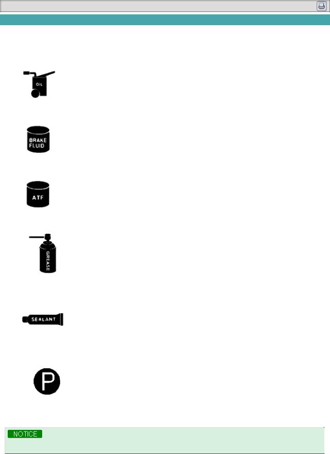
FUNDAMENTAL PROCEDURES
There are six primary symbols used to complement illustrations. There symbols indicate the areas to apply such materials during service.
|
Symbol |
Meaning |
Type |
||||
|
Apply oil |
New engine oil or gear oil as |
|||||
|
appropriate |
||||||
|
Apply brake fluid |
Only brake fluid |
|||||
|
Apply automatic transmission fluid |
Only ATF |
|||||
|
(ATF) |
||||||
|
Apply grease |
Appropriate grease |
|||||
|
Apply sealant |
Appropriate sealant |
|||||
|
Apply petroleum jelly |
Appropriate petroleum jelly |
|||||
Whenever special oil or grease is required, it will be shown in the illustration.
NOTICES, CAUTIONS, AND WARNINGS
As you read through the various procedures, you will encounter Notices, Cautions and Warnings. Each one is there for a specific purpose. Notices give you added information that will assist you in completing a particular procedure. Cautions
present you from making an error that could damaged the vehicle. Warnings remind you to be especially careful in specific areas where carelessness can cause personal injury.
The following items contain general procedures you should alwys follow when working on a vehicle :
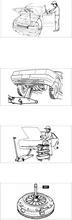
PROTECTION OF THE VEHICLE
•Always cover fenders, seats, and floor areas before starting work.
Operate the engine only in a well-ventilated area to avoid carbon monoxide poisoning.
A WORD ABOUT SAFETY
The following precautions must be followed when jacking up the vehicle:
1.Block the wheels.
2.Use only the specified jacking positions.
3.Support the vehicle with safety stands.
The engine compartment must be clear of tools and people before starting the engine.
PREPARATION OF TOOLS AND MEASURING EQUIPMENT
1. All necessary tools and measuring equipment should be available before starting any work.
SPECLAL SERVICE TOOLS (SST’S)
1.Use special service tools when they are required. SST’s can be found under «preparation» prior to any procedure requiring them.
REMOVAL OF PARTS
1.Begin work only after first learning which parts and subassemblies must be removed and disassembled for replacement for repair.
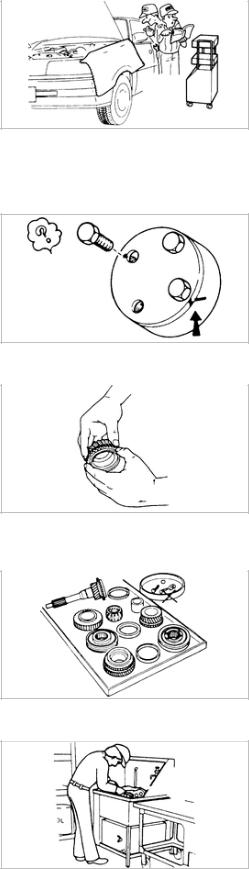
DISASSEMBLY
1.If the disassembly procedure is complex, requiring many parts to be disassembled, all parts should be disassembled in a way that will not affect their performance or external appearance and identified so that assembly can be performed easily and efficiently.
2.Inspection of parts
When removed, each part should be carefully inspected for malfunction, deformation, damage, or other problems.
3.Arrangement of parts
All disassembled parts should be carefully arranged for assembly. Separate or identify the parts to be replaced form those that will be reused.
4.Cleaning parts for reuse
All parts to be reused should be carefully and thoroughly cleaned according to the appropriate method.
REASSEMBLY
Standard values, such as torques and certain adjustments, must be strictly observed in the assembly of all parts. When removed, the following parts should be replaced with new ones:
1.Oil seals
2.O-rings
3.Cotter pins
4.Gaskets
5.Lock washers
6.Nylon nuts
Depending on location:
1.Sealant should be applied or new gaskets used.
2.Oil should be applied to the moving components of parts.
3.Specified oil or grease should be applied at the prescribed locations (such as oil seals) before assembly.
ADJUSTMENT
1. Use appropriate gauges and/or testers when making adjustments.
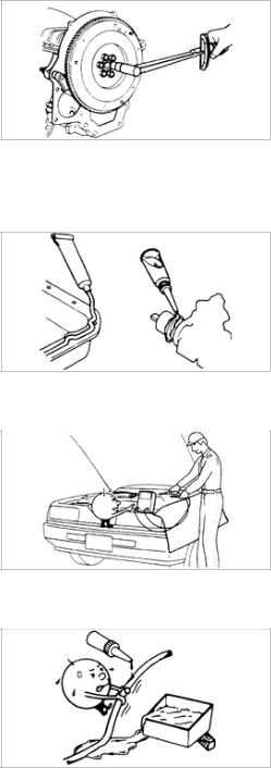
RUBBER PARTS AND TUBING
1. Prevent gasoline or oil from getting on rubber parts or tubing.
ELECTRICAL TROUBLESHOOTING TOOLS
1.Test Light
The test light, as shown in the figure, uses a 12V bulb. The two lead wires should be connected to probes. The test light is used for simple voltage checks and in checking for short circuits.
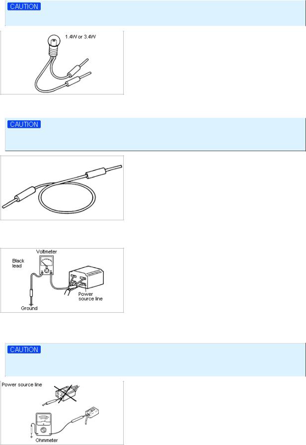
When checking the engine control module (ECM), never use a bulb exceeding 3.4W.
2.Jumper Wire
The jumper wire is used for testing by shorting across switch terminals and ground connections.
Do not connect a jumper wire from the power source line to a body ground. Such a connection may cause damage to harnesses or electronic components.
3.Voltmeter
The DC voltmeter is used to measure circuit voltage. A voltmeter with a range of 15V or more is used by connecting the positive (+) probe to the point where voltage is to be measured and the negative (-) probe to a body ground.
4.Ohmmeter
The ohmmeter is used to measure the resistance between two points in a circuit to check for continuity, and in diagnosis of short circuits.
Do not attempt to connect the ohmmeter to any circuit to which voltage is applied ; this may bum or otherwise damage the ohmmeter.
ELECTRICAL PARTS
1.Battery Cable
Before disconnecting connectors replacing electrical parts, disconnect the negative battery cable.
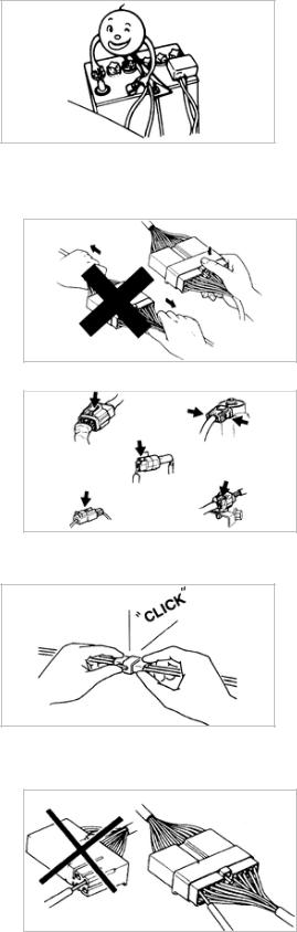
CONNECTORS
1.Removal of connector
(1)Never pull on the wiring harness when disconnecting connectors.
(2) Connectors can be removed by pressing or pulling the lock lever..
2.Locking a connector
Listen for a click when locking connectors. This sound indicates that they are securely locked.
3.Inspection
(1)When a tester is being used to check for continuity or to measure voltage, insert the tester probe from the wire harness side.
(2)Check the terminals of waterproof connectors from the connector side, because they cannot be accessed from the wire harness side.
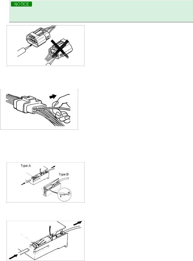
•Use a fine wire to prevent damage to the terminal.
•Do not damage the terminal when inserting the tester lead.
Terminals
1.Inspection
Pull lightly on individual wires to ensure that they are secured in the terminal.
2.Replacement or terminals
Use the appropriate tools to remove the terminal as shown.
When installing the terminal, be sure to insert it until it locks securely.
(1)Female
Insert a thin piece of metal from the terminal side of the connector, and with the terminal locking tab pressed down, pull the terminal out from the connector.
(2)Male
Insert a thin piece of metal from the terminal side of the connector, and with the terminal locking tab pressed down, pull the terminal out from the connector.
3.Sensors, switches, and relays
Always handle sensors, switches, and relays carefully. Do not drop them or accidently strike them against other parts.
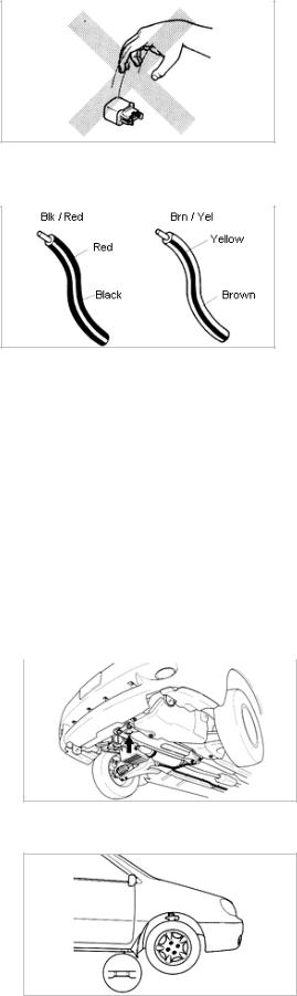
4.Wiring color codes.
Two-color wires are indicated by two color code symbols. The first code symbol indicates the base color of the wire, and the second the color of the stripe on the base color.
|
Code |
Color |
Code |
Color |
|
BLK |
Black |
ORN |
Orange |
|
BRN |
Brown |
PNK |
Pink |
|
GRN |
Green |
RED |
Red |
|
GRY |
Gray |
VIO |
Violet |
|
BLU |
Blue |
WHT |
White |
|
LT BLU |
Light Blue |
YEL |
Yellow |
|
LT GRN |
Light Green |
LT GRY |
Light gray |
JACK AND SAFETY STAND POSITIONS
1.Front end
(1)Jack position :
At the front subframe
2.Safety stand positions :
(1)On both sides of the side sills
3. Rear end
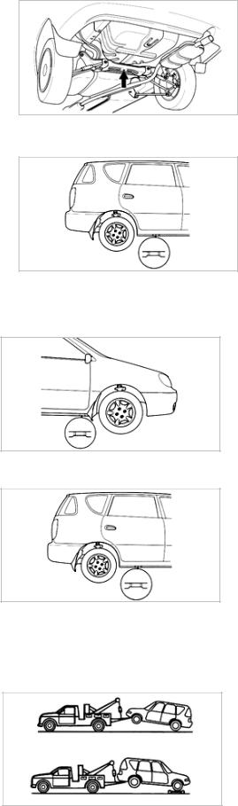
(1)Jack position :
At the center of the rear crossmember
4.Safety stand positions :
(1)On both sides of the side sills
VEHICLE LIFT (2-SUPPORT TYPE) POSITIONS
1.Front end / Rear end Side sills (both sides)
2.Rear end
Side sills (both sides)
TOWING
•Proper towing equipment is necessary to prevent damage to the vehicle.
Always observe laws and regulations applicable to vehicles in tow. As a general rule, towed vehicles should be pulled with the driving wheels off the ground. If excessive damage or other conditions prevent towing the vehicle with the driving wheels off the ground, use wheel dollies.
![]()
With either automatic or manual transmission :
1.Set the ignition switch in the ACC position.
2.Place the selector lever or shift lever in N (Neutral).
3.Release the parking brake.
•Do not tow the vehicle backward with driving wheels on the ground. This may cause internal damage to the transmission.
•Do not use the hook loops under the front and rear of the vehicle for towing purposes. These hook loops are designed ONLY for transport tie-down. If tie-down hook loops are used for towing, the front/rear bumper will be damaged.
VIN locations
• Vin locations
Vehicle identification number arrangement
ENGLISH/METRIC CONVERSION TABLE
|
LENGTH |
|||
|
inch («) |
25.4 |
millimeters (mm) |
|
|
foot (ft.) |
0.3048 |
meters (m) |
|
|
yard (yd.) |
0.9144 |
meters |
|
|
mile |
1.609 |
kilometers (km) |
|
|
AREA |
|||
|
inch² (in²) |
645.2 |
millimeters² (mm²) |
|
|
6.45 |
centimeters² (cm²) |
||
|
Foot² (ft²) |
0.0929 |
meters² (m²) |
|
|
yard² (yd³) |
0.8361 |
meters² (m²) |
|
|
inch³(in³) |
VOLUME |
||
|
16387 |
mm³ |
||
|
16.387 |
cm³ |
||
|
quart (qt.) |
0.0164 |
liters (l) |
|
|
0.9464 |
liters |
||
|
gallon (gal.) |
|||
|
3.7854 |
liters |
||
|
yard³ (yd³) |
|||
|
0.7646 |
meters³(m³) |
||
|
MASS |
|||
|
pound (lb.) |
0.4536 |
kilograms (kg) |
|
|
ton |
907.18 |
kilograms(kg) |
|
|
FORCE |
|||
|
kilogram (kg) |
9.807 |
newtons (n) |
|
|
ounce (oz.) |
0.2780 |
newtons |
|
|
pound (lb) |
4.448 |
newtons |
|
|
ACCELERATION |
|||
|
foot/second² (ft/sec²) |
0.3048 |
meter/sec² (m/s²) |
|
|
inch/second² (in/sec²) |
0.0254 |
meter/sec² (m/s²) |
|
|
TORQUE |
|||
|
pound-inch (lb-in) |
0.11298 |
newton-meters (N·m) |
|
|
pound-foot (lb-ft) |
1.355 8 |
newton-meters (N·m) |
|
|
POWER |
kilowatts (kW) |
||
|
horsepower (hp) |
0.746 |
||
|
PRESSURE |
|||
|
pounds/inch² (psi) |
6.895 |
kilopascals (kPa) |
|
|
ENERGY |
|||
|
foot-pound |
1.355 8 |
joules (J) |
|
|
kilowatt-hour |
3,600,000 |
joules (J) |
|
|
FUEL PERFORMANCE |
|||
|
miles/gallon (mpg) |
0.4251 |
kilometers/liter (km/l) |
|
|
VELOCITY |
|||
|
miles/hour (mph) |
1.6093 |
kilometers/hour |
|
|
TEMPERATURE |
|||
|
to convert fahrenheit temperature to Celsius |
C |
5/9 (F-32) |
|
|
temperature, use formula : |
F |
9/5 C (+32) |
|
|
UNITS |
|||
|
ft-lb or in-lb (N·m) |
Torque |
||
|
rpm |
Rotational speed |
||
|
A |
Amperes |
||
|
V |
Volts |
||
|
Ω |
Ohms (resistance) |
|
|
psi (kPa) |
Pressure |
|
|
inHg (mmHg) |
Pressure (usually negative/vacuum) |
|
|
W |
Watts (electrical power) |
|
|
US qt (liters) |
Volume |
|
|
in (mm) |
Length |
|
|
ABBEREVIATIONS |
||
|
ABDC |
After bottom dead center |
|
|
ABS |
Anti-lock braking system |
|
|
A/C |
Air conditioner |
|
|
ACC |
Accessories |
|
|
A/T |
Automatic transaxle |
|
|
ATDC |
After top dead center |
|
|
ATF |
Automatic transmission fluid |
|
|
BBDC |
Before bottom dead center |
|
|
BTDC |
Before top dead center |
|
|
CMP |
Camshaft position sensor |
|
|
DIS |
Distributorless ignition system |
|
|
DLC |
Data link connector |
|
|
DOHC |
Dual overhead camshaft |
|
|
EBD |
Electronic brake-force distribution |
|
|
ECM |
Engine control module |
|
|
ECT |
Engine coolant temperature |
|
|
E/L |
Electrical load |
|
|
EX |
Exhaust |
|
|
GND |
Ground |
|
|
HLA |
Hydraulic lash adjuster |
|
|
HO S |
Heated oxygen sensor |
|
|
IAT |
Intake air temperature |
|
|
IGN |
Ignition |
|
|
IN |
Intake |
|
|
INT |
Intermittent |
|
|
IAC |
Idle air control |
|
|
LH |
Left hand |
|
|
M |
Motor |
|
|
MAF |
Mass air flow |
|
|
MIL |
Malfunction indicator lamp |
|
|
M/S |
Manual steering |
|
|
M/T |
Manual transaxle |
|
|
OBD |
On-board diagnosis |
|
|
OFF |
Switch off |
|
|
ON |
Switch on |
|
PCV |
Positive crankcase ventilation |
|
P/S |
Power steering |
|
PRC |
Pressure regulator control |
|
P/W |
Power window |
|
RH |
Right hand |
|
SFI |
Sequential fuel injection system |
|
SST |
Special service tool |
|
SW |
Switch |
|
TCS |
Traction control unit |
|
TDC |
Top dead center |
|
TNS |
Tail number side |
|
TPS |
Throttle position sensor |
|
TWC |
Three way catalyst |
|
WU-TWC |
Warm-up three-way catalyst |
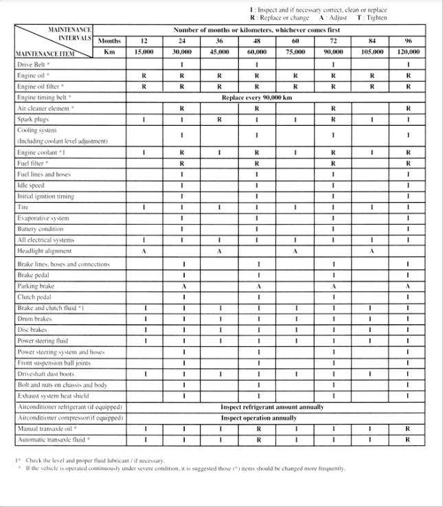
Scheduled maintenance services
Follow schedule if the vehicle is mainly operated where none of the following conditions apply.
•Repeated short-distance driving.
•Driving in dusty conditions.
•Driving with extended use of brakes.
•Driving in areas where road salt or other corrosive materials are used.
•Driving on rough and/or muddy roads.
•Extended periods of idling and/or low-speed operation.
•Driving for prolonged periods in cold temperatures and/or extremely humid climates.
Maintenance Schedule (Except for Europe)


Engine Electrical System
Engine Electrical System
General Information
2001 > 1.8L DOHC >
GENERAL DESCRIPTION
Ignition system overview
The Dual Overhead Cam(DOHC) Engine Ignition System is now a Distributorless Ignition System(DLI) type. This system is similar to the one currently used on Sephia/Shuma vehicles. The key components of this system are :
•2 Separate Coil Packs
•A Crankshaft Position Sensor that provides engine RPM information to the ECM.
•An Ignition Control Module built into the ECM.
•A Canshaft Position Sensor that provides engine firing order information to the ECM
•Spark Plug Wires and Spark Plugs
Ignition system function
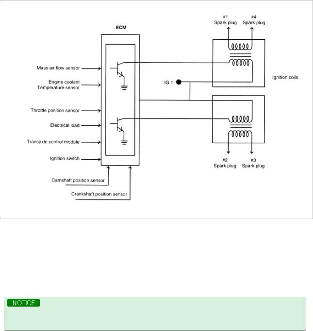
In a conventional ignition system, the ignition coil produces a high voltage current and the disributor thenrelays this current at the required time, to each spark plug. In the disctributirless ignition system, two sensors the camshaft position sensor and the crankshaft position sensor, tell the Engine Control Module (ECM) which cylinder is ready to fire.
The ECM then sends an ignition signal to an electronic ignition coil. This ignition coil then produces and sends a high voltage current to the proper spark plug.
Electronic spark advance system
Ignition Timing is determined and set within the ECM based on signals from various sensors and switches.
Optimum performance is gained with this system. The ECM varies ignition timing according to engine speed, intake air amountm coolant temperature and other conditions.
•Timing specification at idle is : 8 ± 5° BTDC
•Timing is not adjustable.
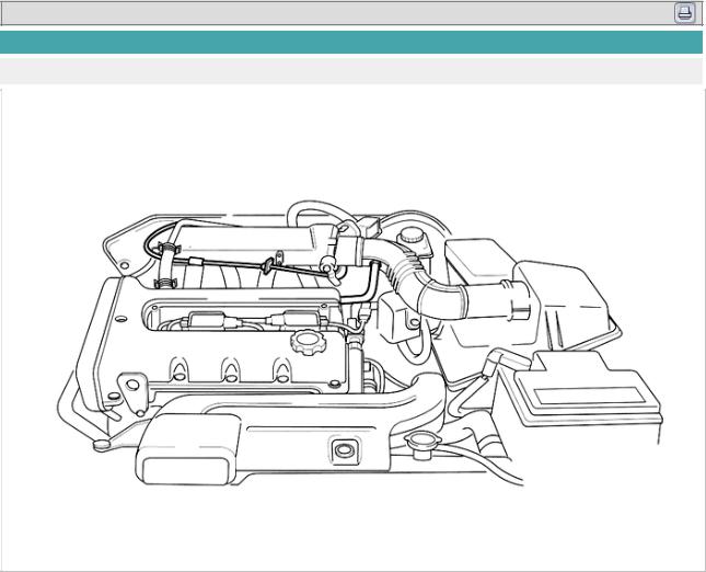
Ignition system components
The mechanical, rotating high-voltage distrivutor mechanism has been replaced by static electronically controlled components. These components are described below.
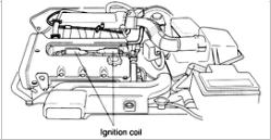
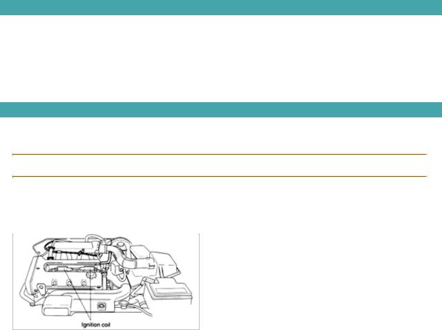
Ignition coil
1.Two ignition coil are used in this system. The engine locates them directly above the #2 and #4 spark plugs. The coil resistance is dentical for these two coils and there is no maintenance required for them.
If determined to be faulty, they must be replaced.
High-tension leads
The high-tension leads connect the two ignition coils to the spark plugs. Their function is basically the same as on the previous system. Because of their shorter length, the DLI high-tension leads enhance the ignition systems delivered voltage. In addition, they reduce the wave interference from one high tension wire to another.
Spark plugs
The spark plugs provide the air gap necessary to produce an arc from the electrical energy coming in from the ignition coil. This arc then ignites the fuel/air mixture in the cylinder, producing power.
![]()
2001 > 1.8L DOHC >
DIAGNOSIS
|
Problem |
Possible Cause |
Action |
|
|
Engine light is «ON» |
Engine control module detects fault |
Check engine module. Repair as |
|
|
in system |
required |
||
|
Engine runs rough |
Spark plug failure |
Check, clean or replace plugs |
|
|
High-tension lead arcing to ground |
Replace high-tension leads |
||
|
Ignition coil(s) faulty |
Check/replace ignition coil |
||
|
CMP sensor faulty |
Check/replace sensor |
||
|
CKP sensor faulty |
Check/replace sensor |
||
|
Engibe fails to start, starter |
Fuse failure |
Check/replace IGN fuse |
|
|
turning |
|||
|
Low battery current |
Check charging system |
||
|
Ignition coil(s) failure |
Check/replace coil(s) |
||
|
CMP sensor failure |
Check/replace sensor |
||
|
CKP sensor failure |
Check/replace sensor |
||

2001 > 1.8L DOHC >
SPECIFICATIONS
Fastener tightening specifications
|
Item |
||
|
Ignition coil bolt |
5~7.2 lb-ft (7~10N·m, 0.7~10kg-m) |
|
|
Spark plugs |
18~22lb-ft (25-30N·m, 2.5~3.0kg-m) |
|
SPECIFICATIONS
General specifications
|
Item |
TBD |
||||||
|
Engine idle speed |
800 ± 50 rpm |
||||||
|
Ignition coil |
Type |
Dual coil |
|||||
|
Primary coil resistance |
0.45~0.55Ω at 68°F (20°C) |
||||||
|
Secondary coil resistance |
13~15kΩ at 68°F (20°C) |
||||||
|
High-tension lead |
16kΩ per 3.28feet (1m) |
||||||
|
Spark plug gap |
0.027~0.031in (0.7~0.8mm) |
||||||
|
Spark plug type |
BKR6E |
||||||
|
Starter |
|||||||
|
Engine/Trans |
TBD |
||||||
|
Item |
M/T |
A/T |
|||||
|
Starter |
Type |
Direct |
Gear reduction |
||||
|
Output |
12V — 0.9kW |
12V — 1.2kW |
|||||
|
Brush length |
Standard |
0.67in (17mm) |
0.49in (12mm) |
||||
|
Minimum |
0.45in (11.5mm) |
0.28in (7mm) |
|||||

Engine Electrical System
Engine Electrical System
Ignition System

Engine Electrical System
Engine Electrical System
Ignition System — Ignition Coil
2001 > 1.8L DOHC >
INSPECTION
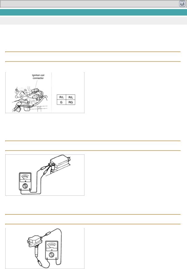
Voltage check
1.Disconnect negative battery cable.
2.Disconnect ignition coil connector.
3.Turn ignition switch to «ON».
4.Measure voltage at red and blue wires at ignition coil connector. Voltage : approximately 12volts
5.If not voltage check main fuse, ignition switch and wire harness.
Resistance check
1.Using an ohmmeter check resistance of primary coil. Connect one lead of ohmmeter to positive (+) terminal and other lead to each negative (-) terminal. If not within specification, replace coil.
Remember that unit has two coil assemblies, so both must be checked. Primary coil resistance : 0.45~0.55Ω @ 68°F (20°C)
2.Using an ohmmeter, check resistance of the secondary coil. If not within specification, replace coil. Remember that you must check resistance of both top and bottom secondary coil. If one is out of specification replace the whole unit.
Secondary coil resistance : 13~15Ω @ 68°F (20°C)
REMOVAL
1.Disconnect battery cable.
2.Disconnect high-tension leads.
3.Disconnect ignition coil connector.
4.Remove four ignition coil mounting bolts.
5.Remove ignition coils.
INSTALLATION
1.Position two coils above No. 2 and No. 4 spark plugs, and firmly push down to connect.
2.Insert and tighten four ignition coil mountinh bolts. Tightening torque : 14~19lb-ft (19~25N·m, 1.9~2.6kg-m)
3.Reconnect ignition coil connectors.
4.Reattach high tension leads. Lead are marked for correct connection.
5.Reconnect battery cable.

Engine Electrical System
Engine Electrical System
Ignition System — Spark Plug
2001 > 1.8L DOHC >
REMOVAL
Do not attempt any maintenance on spark plugs if engine is hot.
1.Disconnect negative battery terminal.
2.Carefulley remove high-tension leads.
3.Use compressed air to blow any dirt or debris from around spark plug hole.
4.Check that spark plug fits squarely spark plug socket and remove spark plug.
INSTALLATION
1.Install spark plug into cylinder head.
Tightening torque : 18~22lb-ft (25~30N·m, 2.5~3.0kg-m)
2.Reconnect high-tension leads.
3.Reconnect negative battery cable.
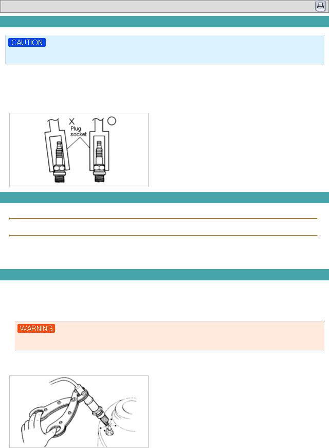
INSPECTION
1.Reconnect negative battery cable.
2.Connect spark plug to high-tension lead.
3.Hold spark plug with insulated pliers 0.2 to 0.39 inch (5~10mm) from a ground.
DO NOT TOUCH VEHICLE BODY DURING FOLLOWING INSTRUCTIONS.
4.While holdung spark plug, have a second person crank engine. Verify that a strong blue spark jumps from spark plug to ground.
5.If there is no spark or the spark is weak, check for, and implement correction :
A.Carbon deposits. Clean out or replace plug.
B.Oil fouling. Correct oil problem, replace plug.
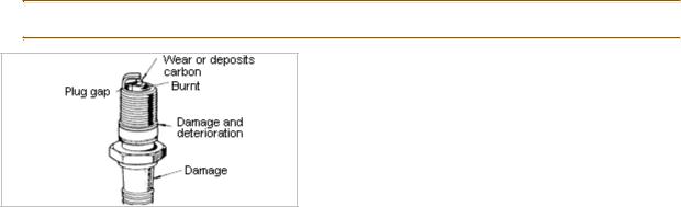
C.Worn or burnt electrode. If present, replace plug.
D.Broken or burned ceramic insulator. If present replace plug.
E.Damaged spark plug ring. If so, replace ring.
F.Improper spark plug gap. Regap if possible, otherwise replace plug. Gap : 0.027~0.031in (07~0.8mm)

Engine Electrical System
Engine Electrical System
Ignition System — Spark Plug Cable
![]()
2001 > 1.8L DOHC >
INSPECTION
High-tension leads
1.Disconnect from coil spark plugs.
2.Check for breaks in insulation.
3.Check inside high-tension lead connectors for corrosion or carbon deposits.
4.Connect high-tension lead to an ohmmeter and check resistance. Resistance : 16kΩ per 3.28 feet (1m)
5.Replace if defective.

2001 > 1.8L DOHC >
INSPECTION
Ignition timing
Ignition timing can be thrown off for two reasons :
A problem with a sensor, which will be detected by ECM or a misalignment of camshaft to crankshaft. This last problem indicates a problem with timing belt, which is covered in Group Engine. There is no need to adjust engine timing after replacement of a coil.
Check procedure
1.Warm engine and let idle.
2.Turn all other electrical system OFF.
3.Connect timing ligh to high-tension lead number one.
4.Check that ignition timing mark on crankshaft pulley aligns with timing mark on engine block.
REMOVAL
Camshaft position sensor
1.Disconnect negative battery cable.
2.Disconnect two wire harness.
3.Remove mounting bolts.
4.Remove sensor from the cylinder head.

Engine Electrical System
Engine Electrical System
Charging System

2001 > 1.8L DOHC >
CIRCUIT DIAGRAM
The generator has a self-diagnostic function that illuminates the generator warning light when there is low or no voltage output generated by the charging system.

Engine Electrical System
Engine Electrical System
Charging System — Alternator

2001 > 1.8L DOHC >
REMOVAL
1.Removal negative battery cable.
2.Open B terminal cover cap.
3.Remove B terminal nut.
4.Remove B terminal lead.
5.Disconnect generator L and S terminal connectors.
6.Loosen pivot bolt and tensioner mounting bolt. Do not remove.
7.Relieve tension on drive belt by rotating adjustment bolt.
8.Remove drive belt from generator pulley.
9.Remove tensioner mounting bolt and belt tensioner.
10.Remove generator pivot bolt.
11.Loosen bolt at base of adjusting bracket and rotate the bracket up.
12.Lift generator from engine compartment.
INSTALLATION
1.Position generator on engine.
2.Install pivot bolt (leave loose).
3.Rotate bracket into position on adjustment bracket.
4.Place belt tensioner into position on top of generator.
5.Install tensioner mounting bolt (leave loose).
6.Place drive belt on generator pulley.

7.Adjust belt tension by rotating adjustment bolt.
Allowable deflection :
New belt : 0.23~0.31in (6~8mm) Old belt : 0.28~0.35in (7~9mm)
8.Tighten tensioner bolt.
Tighten tensioner bolt to : 14~19lb-ft (19~26N·m)
9.Tighten pivot bolt and bracket bolt.
Tighten pivot and bracket bolt to : 28~38lb-ft (38~51N·m)
10.Connect generator L and S terminal connectors.
11.Connect B terminal lead.
12.Install and tighten B terminal nut.
13.Close B terminal nut cover.
14.Install air intake inlet pipe and tighten end clamp.
15.Connect top hose to air intake inlet pipe.
16.Install front air intake inlet pipe bolts.
17.Connect negative battery cable.
1)Be sure battery connections are not reversed. This will damage rectifier.
2)Do not use highvoltage testers, such as a megger. They will damage the rectifier.
3)Remember that battery voltage is always applied to alternator B terminal.
4)Do not ground L terminal while engine is running.
5)Do not start engine while L and S terminals are disconnected from generator.
DISASSEMBLY
Insert protective material in the jaws of the vise.
1. Remove four cap screws from rear housing.

2.Use a 200-watt soldering iron to heat the rear of bearing box to allow the bearing to be removed from rear housing.
If bearing box is not heated, bearing cannot be pulled out of rear housing. The rear bearing and rear housing fit together very tightly.
3. Use a flat-blade screwdrive to separate front housing from stator.
•Be careful not to lose the stopper spring that fits around the rear bearing.
•Insert protective material in the jaw of the vise.
4. Place rotor in a vise and loosen locknut, then disassemble pulley, rotor and front housing.

5.If necessary, remove front bearing using a socket and a hand press or vise.
6.Remove rear bearing with a bearing puller.
7.Remove B terminal nut and insulating bushing.
8.Remove five screws holding the rectifier and brush holder.
9. Separate rear bracket and stator.
10. Use a soldering iron to remove solder from rectifier and stator leads and then remove IC regulator.
Disconnect quickly. If soldering iron is used for more than 5 seconds, rectifier may be damaged by heat.

11. Replace brushes. Remove solder from pigtail and then remove brush.
INSPECTION
1.Rotor
(1)Measure resistance between slip rings with a ohmmeter. If it is not within standard resistance, replace rotor.
Standard resistance : 3.5~4.5Ω
(2)Check for continuity between slip ring and core with a circuil tester. Replace rotor if there is continuity.
(3)If slip ring surface is rough, smooth with a lathe or fine sandpaper.
2.Stator
(1)Check for continuity between stator coil leads with a circuit tester.
(2)Replace stator if there is no continuity.
![]()
(3)Check for continuity between stator coil leads and core with a circuit tester.
(4)Replace stator if there is continuity.
3.Rectifier
(1)Check for continuity between each diode with an ohmmeter.
|
Negative (Black) |
Positive (Red) |
Continuity |
||
|
E |
Pn, P ,P ,P |
○ |
||
|
B |
Pn, P ,P ,P |
× |
||
|
T |
Pn, P ,P ,P |
× |
||
|
Pn, P , P ,P |
E |
× |
||
|
B |
○ |
|||
|
Pn, P ,P ,P |
T |
○ |
||
|
T |
× |
|||
|
(2) Replace if necessary. |
||||

4.Brush
If brushes are worn to or beyond, limit. replace them.
Standard : 0.85in (21.5mm) Minimum : 0.32in (8.0mm)
5.Brush spring
(1)Measure force of brush spring with a spring pressure gauge.
(2)Replace the spring if necessary.
Standard force : 0.71~0.93lb-ft (3.1~4.1N·m, 0.32~0.42kg-m) Minimum : 0.36~0.52lb-ft (1.60~2.4N·m, 0.16~0.24kg-m)
Read spring pressure with brush tip projecting 0.08in (2mm).
6.Bearing
(1)Check for abnormal noise, looseness insufficient lubrication, etc.

(2) Replace bearing(s) of if there is any abnormality.
RESSEMBLY
1.Assemble brush and solder pigtail so that wear limit line of brush projects 0.079~0.118in (2~3mm) out of brush holder.
2. Assemble regulator and solder with rectifier and stator leads.
Disconnect quickly. If soldering iron is used for more than 5 seconds rectifier may be damaged by heat.
3.Assemble rear bracket and stator.
4.Tighten screws holding rectifier and brush holder. Tightening torque : 1.5~4.0lb-ft (2.0~5.4N·m, 0.2~0.55kg-m)
5.Tighten B terminal nut and insulating brushing.
6. Assemble rear bearing and stopper spring.

Make sure groove on bearing rim is facing slip ring side.
7.Assemble front bearing. Using a socket which exactly fits outer race of bearing, carefully push in front bearing. Use a hand press or vise.
Insert protective material in the jaws of the vise.

Engine Electrical System
Engine Electrical System
Charging System — Battery

2001 > 1.8L DOHC >
RECHARGING
1.Slow charging
It is not necessary to remove vent caps to perform a slow charge.
|
Battery |
Slow charge (A) |
Quick charge (A) |
|
PT48 — 24GL MF |
Under 5 |
Maximum 20 |
2.Quick charging
Remove battery from vehicle and remove vent caps to perform a quick charge.
•BEFORE PERFORMING MAINTENANCE OR RECHARGING BATTERY, TURN OFF ALL ACCESSORIES AND STOP ENGINE.
•NEGATIVE CABLE MUST BE REMOVED FIRST AND INSTALLED LAST.
•SET BATTERY IN WATER WHEN QUICK CHARGING TO PREVENT OVERHEATING BATTERY.

2001 > 1.8L DOHC >
INSPECTION
Terminal and cable
1.Check that battery terminal connections are tight to ensure good electrical connections.
2.Check for corroded or frayed battery cables.
3.Check rubber protector on positive terminal for proper coverage.
4.Clean terminals, if necessary and lightly coat them with grease.

2001 > 1.8L DOHC >
Circuit operation
When the ignition switch is turned to ON or START, battery voltage is applied to the charge indicator and terminals B and S of the alternator. After the engine has started and is running, the generator produces alternating current. The direct current and voltage keeps the battery fully charged and provides power to operate the vehicle’s electrical system.The amount of direct current and voltage of the alternator outputs is controlled by the voltage regulator.
If the voltage regulator senses that the output of the alternator is not sufficient for charging the battery, it will ground terminal L of the alternator and the charge indicator will illuminate.

2001 > 1.8L DOHC >
COMPONENTS

2001 > 1.8L DOHC >
DIAGNOSTIC CHART
|
Step |
Inspection |
Action |
|||
|
1 |
Check battery voltage |
Yes |
Go to next step. |
||
|
Specification : Above 12.4V |
No |
Check battery |
|||
|
2 |
Start engine and check if generator warning |
Yes |
Go to step 4. |
||
|
light goes out |
No |
Go to next step. |
|||
|
3 |
Check if voltage at generator terminals are |
||||
|
correct |
|||||
|
Yes |
Check wiring harness between battery |
||||
|
and terminal B. |
|||||
|
No |
• Check wiring harness. |
||||
|
• Replace generator. |
|||||
|
4 |
1.Connect an ammeter (80A minimum) |
||||
|
between terminal B and terminal B harness |
|||||
|
connector. |
|||||
|
2.Start engine. |
|||||
|
3.Turn all electrical loads ON and depress |
Yes |
Charging system normal. |
|||
|
brake pedal. |
|||||
|
4.Check if output current is 65A or more at |
|||||
|
2,500~3,000 rpm. |
|||||
|
No |
Go to next step. |
||||
|
5 |
Check drive belt tension OK? |
Yes |
Replace generator. |
||
|
No |
Adjust drive belt tension. |
||||
 Loading…