- Manuals
- Brands
- Kemppi Manuals
- Welding System
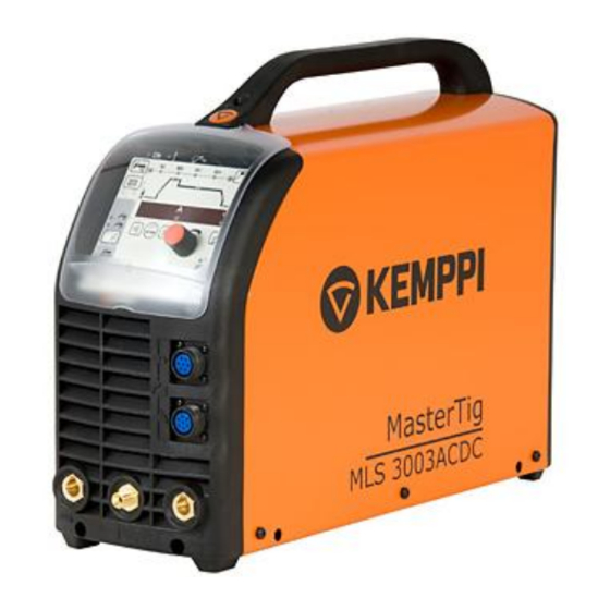
- MasterTig MLS 3003 ACDC
Manuals and User Guides for Kemppi MasterTig MLS 3003 ACDC. We have 3 Kemppi MasterTig MLS 3003 ACDC manuals available for free PDF download: Service Manual, Operating Manual, Operation Instructions Manual
Сварочный инвертор KEMPPI MasterTig MLS 3003 ACDC – это многофункциональный источник питания для трехфазных сетей (с возможностью работы при различном напряжении питания – напряжение может составлять от 230 до 460 В) с максимальным током 300 А, предназначенным для профессиональной сварки штучными электродами, способами TIG и TIG в импульсном режиме, на постоянном и переменном токе. Кроме того, устройство позволяет сочетать переменный и постоянный ток и работать в режиме MIX TIG (комбинированная сварка TIG). Мощность источника тока регулируется транзисторами IGBX работающими на частоте около 65 кГц.
Модели серии MasterTig MLS ACDC подходят для сварки TIG всех металлов, особенно алюминия и нержавеющей стали, а также для сварки ММА. Их можно использовать как для ручной, так и для автоматизированной сварки. В эту серию входят наиболее универсальные и современные аппараты для сварки TIG.
Для аппарата можно приобрести две различные сменные панели управления, имеющие все основные функции, необходимые для сварки TIG, а также множество полезных дополнительных функций, повышающих качество и производительность сварочных работ:
- Панель управления ACS – основные регулировки и режим MIX TIG.
- Панель управления ACX – множество функций, которые облегчают сварочные работы и повышают скорость их выполнения. Например, функция Minilog позволяет повышать или понижать напряжение во время сварки нажатием на выключатель горелки. Функция 4T LOG помогает начать и закончить сварку.
Mastertig MLS™ 3003 ACDC оснащен собственным блоком охлаждения для горелок с водяным охлаждением – MasterCool 30.
Особенности
- MicroTack – быстрое и качественное выполнение прихваточного шва обеспечивает качество окончательной сварки.
- MIX TIG – преимущества комбинации переменного и постоянного тока при сварке одного шва. Облегчает сварку алюминия и уменьшает деформацию.
- Высокая гладкость шва и широкий диапазон использования оборудования.
- Благодаря применению специальной технологии PFC мощность сварки можно увеличивать до чрезвычайно высокого уровня.
- Данное оборудование включено в реестр ОАО “Газпром”.
Области применения
- Цеха изготовления металлоконструкций
- Судостроительные верфи и морская нефтедобыча
- Химическая и обрабатывающая промышленность
- Механизированная сварка
Руководства и инструкции
- Руководство по эксплуатации (инструкция) KEMPPI MasterTig MLS 3003 ACDC.pdf
- Наглядная брошюра KEMPPI MasterTig MLS 3003 ACDC.pdf
- Гарантийные положения и условия Kemppi.pdf
Комплект поставки
- Сварочный инвертор KEMPPI MasterTig MLS 3003 AC/DC
- Для заказа дополнительных принадлежностей см. раздел Коды заказа ниже.
Технические характеристики
| Характеристика | Значение |
|---|---|
| Напряжение питания 50/60 Гц | 3~, 400 В (±10 %) |
| Номинальная мощность при ПВ 100 % – TIG | 9,2 кВА |
| Номинальная мощность при ПВ 100 % – MMA Напряжение холостого хода | 10 кВА |
| Сетевой кабель H07RN-F | 4G2.5 (5 м) |
| Рекомендованные предохранители (плавкие, с задержкой срабатывания) | 20/16 А |
| Нагрузка при 40 °C ПВ 40 %, TIG | 300 A/22 В |
| Нагрузка при 40 °C ПВ 60 %, TIG | 230 A/19,2 В |
| Нагрузка при 40 °C ПВ 100 %, TIG | 190 А/17,6 В |
| Нагрузка при 40 °C ПВ 40 %,MMA | 250 A (230 В перем. тока, 30 %) /30 В |
| Нагрузка при 40 °C ПВ 60 %,MMA | 230 А/29,2 В |
| Нагрузка при 40 °C ПВ 100 %,MMA | 190 А/27,6 В |
| Диапазон сварочных токов и напряжений – TIG | 3 А/10,0 В – 300 А/22 В |
| Диапазон сварочных токов и напряжений -MMA | 10 А/20,5 В – 250 А/30 В |
| Напряжение холостого хода | 58 В пост. тока |
| Коэффициент мощности при ПВ 100 % | 0,95 |
| КПД при ПВ 100 % | 81 % |
| Штучный электрод, MMA ø | 1,5…5,0 мм |
| Габаритные размеры Д х Ш х В | 500 x 180 x 390 мм |
| Масса | 25 кг |
Коды заказа
| Наименование | Артикул |
|---|---|
| MasterTig MLS 3003 ACDC | 6163003 |
| Панели управления: | |
| ACS | 6162805 |
| ACX | 6162804 |
| Блоки охлаждения: | |
| MasterCool 30 | 6163900 |
| Сварочный кабель: | |
| 16 мм², 5 м | 6184103 |
| 25 мм², 5 м | 6184201 |
| 25 мм², 10 м | 6184202 |
| 35 мм², 5 м | 6184301 |
| 16 мм², 5 м | 6184113 |
| 25 мм², 5 м | 6184211 |
| 25 мм², 10 м | 6184212 |
| 35 мм², 5 м | 6184311 |
| Расходомер аргона с часами | 6265136 |
| Горелки: | |
| TTC 160, 4 м | 627016004 |
| TTC 160, 8 м | 627016008 |
| TTC 160, 16 м | 627016016 |
| TTC 220, 4 м | 627022004 |
| TTC 220, 8 м | 627022008 |
| TTC 220, 16 м | 627022016 |
| TTC 200W, 4 м | 627020504 |
| TTC 200W, 8 м | 627020508 |
| TTC 200W, 16 м | 627020516 |
| TTC 250W, 4 м | 627025504 |
| TTC 250W, 8 м | 627025508 |
| TTC 250W, 16 м | 627025516 |
| Пульты дистанционного управления: | |
| RTC 10 | 6185477 |
| Row 35 Col 1 | 6185407 |
| R11F | 6185478 |
| Транспортные тележки: | |
| T130 | 6185222 |
| T110 | 6185251 |
| T100 | 6185250 |
- Manuals
- Brands
- Kemppi Manuals
- Welding System
- MasterTig MLS 3003 ACDC
- Service manual
-
Bookmarks
Quick Links
Service manual
Mastertig MLS 3003 ACDC
Version 1.2
1
Related Manuals for Kemppi Mastertig MLS 3003 ACDC
Summary of Contents for Kemppi Mastertig MLS 3003 ACDC
-
Page 1
Service manual Mastertig MLS 3003 ACDC Version 1.2… -
Page 2: Technical Data
Technical data 3 ~ 230 V — 10% … 460 V +10%, 50/60 Hz Mains Voltage Mains cable H07RN-F 4G2.5, length 5 m Fuse 20/ 16A delayed fuse Rated power 100% 300A 190A 250A 190A Minimum Current TIG 3A ( AC 5A ) / MMA 10A Open circuit Voltage 58 V Power Factor at nominal values…
-
Page 3: User Interface
User interface Gas connector for TIG torch Welding current connection (negative) Operation panel Remote controller connection TIG -torch control connection Welding current connection (positive) Main switch Gas connector Error code Description Err 3 Overvoltage Err 4 Over heating Err 6 Internal fault, secondary voltage over the limit.
-
Page 4: Setup Functions
Setup functions Entering the advanced setup press and hold the setup and Return buttons at the same time. Changing the level press Setup button shortly The upslope time depends on the welding current Welding current upslope time * The upslope time is fixed The downslope time depends on the welding current Welding current downslope time *…
-
Page 5
Setup functions Start current level in use Start current level Start current level not in use During downslope the current can be ”frozen” onto a certain level, using the start switch Current ”freezing” ”Freeze” function is OFF Torch auxiliary switches are used to select TIG -torch auxiliary switches (RTC memory channels 20) *… -
Page 6
Setup functions Factory setting 20 A Contact ignition current * 3…2 Adjustment range 3…230 A Factory setting 1,0 s. Adjustment range 0,2…2,0 s. Spark ignition duration * …2. Factory setting 10 % of the welding current Downslope cutoff level * 5…4 Adjustment range 5…40 % of the welding current… -
Page 7
Setup functions Factory setting 0,0…15,0 s. Spot welding spot-time * 0…150 s. Factory setting MMA dynamics ** Adjustment range -9 = soft arc, 9 = rough arc 9…0 …9 Factory setting Adjustment range -9 = minimum overrun, 9 = MMA ignition pulse ** 9…0 maximum overrun …9… -
Page 8
Setup functions Factory setting 0,0 s. Pregas time minimum * Adjustment range 0,0…2,0 s. …2. Factory setting 1,0 s. Postgas time minimum * 0…1 Adjustment range 0…10 s. Factory setting -80 % Adjustment range -80…-10 % AC balance minimum * 80…… -
Page 9
Setup functions Factory setting 60 Hz AC frequency ** 50…250 Adjustment range 50…250 Hz Square wave AC waveform ** Sinus wave Factory setting 5 A Half cycle AC 5…20 Adjustment range 5…20 A Factory setting -25 % -50…10 Adjustment range -50…10 % AC balance ** Factory setting 100 % 100…500… -
Page 10
Setup functions Factory setting 50 % MIX TIG AC pulse ratio ** 10… Adjustment range 10…90 % Factory setting 100 % MIX TIG DC level ** 50… Adjustment range 50…150 % Factory setting 10 ms. Spotwelding time * 1…2 Adjustment range 1…200 ms. * Setting is always on ** Adjustable also by the Quick Setup… -
Page 11
Construction L002 A003 Z002 Spark Fans transformer Shunt resistor Main transformer Z004 Difference between 3000 / 3003, resistor R96 missing in 3003 Z003 Main switch, VDRs, EMC-choke… P001 Z001 Under insulator A004 A001 A002 PVC insulator Water cooler connectors… -
Page 12: Main Circuit Diagram
Main circuit diagram…
-
Page 13: Main Circuit Card Z001
Main circuit card Z001 Functions and components: Z001 primary inverter main functions — full bridge topology — switching frequency (50 … 25kHz) 25kHz — electrolytic dc-link capacitors — emc filtering — gate and current transformers…
-
Page 14
Secondary rectifier Z002 Functions and main components Z002 secondary rectifier main functions — rectifies two voltages +60Vdc and -60Vdc — heat sink act as a conductor for positive terminal — stabilizing voltages are made by diode — capacitor multiplier — stabilizing voltage are regulated +-300Vdc (X5, X6) — snubbers for diodes — minus side diodes are insulated from heat sink by mica insulator Grey diodes must be insulated… -
Page 15
Secondary inverter Z003 Functions and main components Z003 secondary inverter main functions — acts as a four level switch matrix (DC+, DC-, Aux+, Aux-) (heat sink, X5, X7, X9) — heat sink act as a conductor for positive terminal — minus side IGBTs are insulated from heat sink by mica insulator — gate drive circuits — protection against gate drive under voltage — optical isolation between control card gate drives… -
Page 16
Pre-inverter (PFC) card Z004 Functions and connectors: — rectifies input input ac-voltages — provides soft start feature — soft-start ptc-resistor — soft start relay — input over voltage, under voltage and phase missing detection — increases rectified input voltage to 725Vdc — topology boost with two parallel paths — switching frequency 25kHz — maximum igbt current 40A peak… -
Page 17: A001 Control Card
A001 Control card Functions and connectors A001 Control Card Main Functions — current control (primary X4, secondary X8) — spark control (X7) — secondary inverter control (X2) — pre- inverter (pfc) and charge relay control (X5) — panel interface (X1) MLS3000 = R96 on / MLS3003 R96 off — magnetic valve control (X9) — fan control (X9)
-
Page 18
A002 Auxiliary power card Functions and connectors A002 Auxiliary Power Supply Main Functions — output voltage 24Vdc — input voltage range (450 … 750)Vdc (X1, X3) — output power 100W continuous with forced cooling — switching frequency 100kHz — topology flyback — forced “hiccup”… -
Page 19
A003 Spark card Functions and connectors A003 HF generator card Main Functions — supply voltage 180Vac (main transformer) (X8, X9) — three parallel power igbts — HF-transformers primary voltage about 500Vdc — max. spark repetition frequency 500Hz with forced cooling (start control, X7) R27 = HF voltage adjusting R27 = HF voltage adjusting… -
Page 20
A004 Interface card Functions and connectors A004 interface card main functions — panel bus interface (X2) — link between control card A001 and outside world (X1) — service and programming interface (X3) — tig control interface with protection against spark and +-100Vdc (X6) — remote control interface with protection against spark and +- 100Vdc (X5) -
Page 21
Measurements Z001, Main circuit card : — Power should be off ! — With these measurements you can find short circuits and partly open circuits that indicates fault in the machine. — Measure diodes in forward and reverse direction. Forward diode threshold voltage is ~0,4V, reverse direction infinite. -
Page 22
Measurements Z004 Pre-inverter, rectifier: — Power should be off ! — With these measurements you can find short circuits and partly open circuits that indicates fault in the machine. — Measure diodes in forward and reverse direction. Forward diode threshold voltage is ~0,5V, reverse direction infinite. -
Page 23
Measurements Z004 Pre-inverter, IGBT: — Power should be off ! — With these measurements you can find short circuits and partly open circuits that indicates fault in the machine. — Measure diodes in forward and reverse direction. Forward diode threshold voltage is ~0,4 V, reverse direction infinite. -
Page 24
Measurements Z003 Secondary inverter — Power should be off — Measure diodes and IGBTs in forward and reverse direction. Forward diode threshold voltage is about 0,45V, reverse direction high. — C-A, C-E, B-C, D-B, ~0,45V diode threshold voltage B-E, 0,7V diode threshold voltage D-C, 0,85V diode threshold voltage A (in+, heat sink) D (aux-) -
Page 25
Connect Kemppi Multipower and digital multimeter with current measuring function to X7-1 (24 VDC) and X7-2 (GND). Switch on Kemppi Multipower and watch current consumption and test the panel functionality. < 300mA is OK (normally 120mA/24V without cooling fans and magnetic valve) •… -
Page 26
Connect MLS-Service power DC+ (= 560Vdc) to wire connector X6 (goes to A002) and DC- to Z004/X8 (X6=560V, X8=0V). Connect Kemppi Multipower with 98 Vdc (24+24+50 Vdc in series) between phases L2, L3. Switch on MLS- Service power and check the panel functionality. -
Page 27
Connect Kemppi Multipower with 22 VAC with current limit 2,5 A between phases L2, L3 Connect Kemppi MLS- Service power DC+ = 560Vdc to wire connector X6 and DC- to Z004/X8 (X6=560V, X8=0V). Again in newer model, connect DC+ to X6 cable going to A002/X1. -
Page 28
Measurements TESTING OF THE SECONDARY OVER VOLTAGE WATCH Connect MLS- Service power voltages (24+24+50)Vdc in series by using PTC-resistor. Set the machine to DC- TIG mode. Connect the test voltage to output DIX terminals of the machine. If machine shows «Err 6» then it is OK. Repeat the test with reversed polarity. -
Page 29
Installation of semiconductors IGBT mounting onto the heat sink The installation surfaces must be clean, even very small particles (0,050mm) between the surfaces increase the gap between heat sink and module, causing module overheating and possibly destruction. Heat transfer paste is spread as an even layer about 0,1 mm thick, onto the modules base plate. -
Page 30
Installation of semiconductors Secondary rectifier Z002 Negative side diodes are insulated from the heat sink by mica insulators. Mica insulators have to be replaced always, when the secondary diode card Z002 is separated from heat sink !!! Heat transferring paste is applied as thin layers on both sides of the mica insulators. -
Page 31
Installation of semiconductors Secondary inverter Z003 Negative side IGBTs are insulated from the heat sink by mica insulators. Mica insulators have to be replaced every time the main circuit card Z003 is disconnected from heat sink !!! Heat transferring paste is applied as thin layers on both sides of the mica insulators. -
Page 32
Notes…
(Ocr-Read Summary of Contents of some pages of the Kemppi MasterTig MLS 3003 ACDC Document (Main Content), UPD: 04 May 2023)
-
4, 4 Setup functions Welding current upslope time * A1 ON The upslope time depends on the welding current OFF The upslope time is fixed Welding current downslope time * A2 ON The downslope time depends on the welding current OFF The downslope time is fixed TIG Antifreeze * A3 ON TIG Antirfeeze is ON OFF TIG Antifreeze is OFF MMA Antifreeze * A4 ON MMA antifreeze is ON OFF MMA a…
-
25, 25 Measurements These tests have to be done after replacing any primary or secondary units. It absolutely important because possible short circuit (e.g. improperly installed mica insulator) might damage machine severely. TESTING OF THE CONTROL CARD AND CONTROL CIRCUITS 1. Disconnect cooling fans (A001/X9) 2. Disconnect (HF, Spark generator card) A003/X8 3. Connect jumpers A001/X14 (overvoltag…
-
28, 28 Measurements 24 VDC 24 VDC 50 VDC PTC PTC TESTING OF THE SECONDARY OVER VOLTAGE WATCH 1. Connect MLS- Service power voltages (24+24+50)Vdc in series by using PTC-resistor. 2. Set the machine to DC- TIG mode. 3. Connect the test voltage to output DIX terminals of the machine. 4. If machine shows «Err 6» then it is OK. 5. Repeat the test with reversed polarity.
… -
24, Kemppi MasterTig MLS 3003 ACDC 24 Measurements Z003 Secondary inverter — Power should be off — Measure diodes and IGBTs in forward and reverse direction. Forward diode threshold voltage is about 0,45V, reverse direction high. — C-A, C-E, B-C, D-B, ~0,45V diode threshold voltage B-E, 0,7V diode threshold voltage D-C, 0,85V diode threshold voltage A (in+, heat sink) B (in-) C (out+-) D (aux-) E (aux+)
… -
22, 22 Measurements Z004 Pre-inverter, rectifier: — Power should be off ! — With these measurements you can find short circuits and partly open circuits that indicates fault in the machine. — Measure diodes in forward and reverse direction. Forward diode threshold voltage is ~0,5V, reverse direction infinite. See the picture below for instructions. — Repeat measurements for all six (6) instances. Pin locations marked in the pictures below. Diodes* Measuring points …
-
16, 16 Pre-inverter (PFC) card Z004 Functions and connectors: — rectifies input input ac-voltages — provides soft start feature — soft-start ptc-resistor — soft start relay — input over voltage, under voltage and phase missing detection — increases rectified input voltage to 725Vdc — topology boost with two parallel paths — switching frequency 25kHz — maximum igbt current 40A peak — output power 10kW with 230Vac supply Factory settings for jumpers: — X17 (1-4) = off — X1…
-
19, Kemppi MasterTig MLS 3003 ACDC 19 A003 Spark card Functions and connectors A003 HF generator card Main Functions — supply voltage 180Vac (main transformer) (X8, X9) — three parallel power igbts — HF-transformers primary voltage about 500Vdc — max. spark repetition frequency 500Hz with forced cooling (start control, X7) R27 = HF voltage adjusting range (8.5 .. 13)kV R27 = HF voltage adjusting range (8.5 .. 13)kV
… -
3, 3 User interface 1. 2. 3. 4. 5. 6. 1. Gas connector for TIG torch 2. Welding current connection (negative) 3. Operation panel 4. Remote controller connection 5. TIG -torch control connection 6. Welding current connection (positive) 7. Main switch 8. Gas connector 7 8. Error code Description Err 3 Overvoltage Err 4 Over heating Err 6 Internal fault, secondary voltage over the limit. Err 8 Maximum overheat time, machine doesn’t cool down fa…
-
26, 26 Measurements TESTING OF THE POWER STAGE 1. Disconnect cooling fans (A001/X9). 2. Disconnect (HF, Spark generator card) A003/X8. 3. Connect jumpers A001/X14 (overvoltage) and A001/X16 (main switch open) on control card A001. 4. Remove insulation plate from the top of Z003. 5. Disconnect Z004/X7 and Z004/X6 to A002/X1. Leave X8 connected. Check again for correct cable !!! (In…
-
10, 10 Setup functions MIX TIG AC pulse ratio ** E10 50 Factory setting 50 % 10… 90 Adjustment range 10…90 % MIX TIG DC level ** E11 100 Factory setting 100 % 50… 150 Adjustment range 50…150 % Spotwelding time * E12 10 Factory setting 10 ms. 1…2 00 Adjustment range 1…200 ms. * Setting is always on ** Adjustable also by the Quick Setup
… -
2, 2 Technical data The device may be repaired only by a person legally authorized perform electric work! Measured values may differ by the type and model of multimeter used. Maximum power can be achieved with 20 kVA generator for the power source. Mains Voltage 3 ~ 230 V — 10% … 460 V +10%, 50/60 Hz Mains cable H07RN-F 4G2.5, length 5 m Fuse 20/ 16A delayed fuse Rated po…
-
31, 31 Installation of semiconductors Secondary inverter Z003 Negative side IGBTs are insulated from the heat sink by mica insulators. Mica insulators have to be replaced every time the main circuit card Z003 is disconnected from heat sink !!! Heat transferring paste is applied as thin layers on both sides of the mica insulators. Absolutely no impurities are allowed on surface of the insulators when mounting them between the heat sink and the IGBTs!…
-
13, 13 Main circuit card Z001 Functions and components: Z001 primary inverter main functions — full bridge topology — switching frequency (50 … 25kHz) 25kHz — electrolytic dc-link capacitors — emc filtering — gate and current transformers
… -
8, Kemppi MasterTig MLS 3003 ACDC 8 Setup functions Pregas time minimum * C1 0.0 Factory setting 0,0 s. 0.0 …2. 0 Adjustment range 0,0…2,0 s. Postgas time minimum * C7 1.0 Factory setting 1,0 s. 0…1 0 Adjustment range 0…10 s. AC balance minimum * C16 -80 Factory setting -80 % — 80… -10 Adjustment range -80…-10 % Pregas time maximum * D1 1 Factory setting 1 s. 0…1 0 Adjustment range 0…10 s. Postgas time maximum * D7 30 Factory setting 30 s. 15… 150 A…
-
23, 23 Measurements Z004 Pre-inverter, IGBT: — Power should be off ! — With these measurements you can find short circuits and partly open circuits that indicates fault in the machine. — Measure diodes in forward and reverse direction. Forward diode threshold voltage is ~0,4 V, reverse direction infinite. — Measuring points have been marked in the picture below. Four (4) measurements must be conducted to be sure of correct operation of Z004. Diodes* Measuring po…
-
30, 30 Installation of semiconductors Secondary rectifier Z002 Negative side diodes are insulated from the heat sink by mica insulators. Mica insulators have to be replaced always, when the secondary diode card Z002 is separated from heat sink !!! Heat transferring paste is applied as thin layers on both sides of the mica insulators. Absolutely no impurities are allowed on surface of the insulators…
-
5, 5 Setup functions Start current level A13 ON Start current level in use OFF Start current level not in use Current ”freezing” A14 ON During downslope the current can be ”frozen” onto a certain level, using the start switch OFF ”Freeze” function is OFF TIG -torch auxiliary switches (RTC 20) * A15 ON Torch auxiliary switches are used to select memory channels OFF Torch auxiliary switches adjust…
-
7, 7 Setup functions Spot welding spot-time * B10 OFF Factory setting 0,0…15,0 s. ON 0…150 s. MMA dynamics ** B11 0 Factory setting — 9…0 …9 Adjustment range -9 = soft arc, 9 = rough arc MMA ignition pulse ** B12 0 Factory setting — 9…0 …9 Adjustment range -9 = minimum overrun, 9 = maximum overrun Start current level * B13 10 Factory setting 10 % of the welding current OFF Mini…
Код: id-10795
Добавить к сравнению
Поделиться ссылкой
Распечатать страницу
Розничная цена
Под заказ
Добавить к сравнению
Поделиться ссылкой
Распечатать страницу
Узнать цену для Юр. лиц- Нашли дешевле? Сообщите!
Характеристики
-
Снято с производства
Y -
Тип сварки / резки
TIG/MMA -
Тип аппарата
Инвертор -
Класс товара
Профессиональный -
Гарантийный срок, лет
2 -
Напряжение сети, В
220/380 -
Диапазон напряжения сети
207-506 -
Класс изоляции
H -
Тип охлаждения
Водяное -
Частота сети, Гц
50/60 -
Число фаз
Трехфазный -
Сварочный ток, от
3 -
Сварочный ток, до
300 -
Способ возбуждения дуги
Бесконтактный -
TIG сварка
Да -
Сварочный ток MMA, А
10 — 250 А
-
Ток в режиме TIG, А
3 — 300 А -
Диаметр электрода (min — max), мм
1.5 — 5.0 мм -
Напряжение холостого хода, В
58 -
Сварочное напряжение, В
10-30 В -
Коэффициент мощности (COS)
0.95 -
Потребляемая мощность, кВА
10 -
Рекомендуемая мощность генератора, кВт
13 -
Дисплей
Есть -
ММА ток при ПВ 100%, А
190 -
TIG ток при ПВ 100%, А
190 -
TIG ток при ПВ 60%, А
230 -
ММА ток при ПВ 35%, А
250 -
КПД, %
81 -
Степень защиты от пыли и влаги
IP 23 -
Сетевой предохранитель
20 -
Рабочая температура
от -20 до +40 -
Транспортировочные колеса
Нет
Инструкция к Kemppi MasterTig MLS 3003 ACDC
Параметры упакованного товара
- Вес, кг25
- Габариты, мм
500x180x390
Производство
- ПроизводительKemppi
- Родина брендаФинляндия
- Страна производстваФинляндия
* Производитель оставляет за собой право без уведомления дилера менять характеристики, внешний вид, комплектацию товара и место его производства.
Информация о технических характеристиках, комплекте поставки и внешнем виде, может отличаться от указанной на сайте. Уточняйте эту информацию у менеджера при оформлении заявки. Если вы заметили ошибку или неточность в описании, пожалуйста, сообщите нам об этом по адресу
sales@adg-svarka.ru
Указанная информация не является публичной офертой
Нашли ошибку?
Описание
Хотите купить Kemppi MasterTig MLS 3003 ACDC по самым выгодным ценам в Москве?
Позвоните нам по номеру 8 (800) 775-12-12 и мы проконсультируем Вас как купить оборудование с максимальной скидкой и сэкономить на доставке в Ваш регион.
Если Вам удобнее вести деловую переписку по электронной почте — пишите нам на Email sales@adg-svarka.ru. Как правило, на письма мы отвечаем в течении 1 рабочего дня.
ВНИМАНИЕ! В нашей компании действует гибкая система скидок. Мы постоянно развиваемся и поэтому получаем возможности для экономии Ваших средств.
Так же вы можете купить Kemppi MasterTig MLS 3003 ACDC в кредит.
Полезные ссылки:
Оплата и доставка.
Условия для Юридических лиц.
Оптовые условия.
Возможно Вас заинтересует
Готов ответить на все Ваши вопросы!

Советы экспертов
Немного о нас
Сегодня наша компания востребована — благодаря безупречной деятельности на рынке сварочного оборудования, мы сумели наработать большую базу довольных клиентов, количество которых постоянно увеличивается. У нас всегда сервис и гарантии!

-

Прямые поставки
Официальные дилеры, есть все необходимые сертификаты
-
В наличии самая популярная продукция
Следим за наличием самых популярных товарных позиций на наших складах
-
Грамотная консультация
Без спешки, по существу готовы ответить на все Ваши вопросы
-
Адекватные цены
Все поставки осуществляются без посредников
-
Бесплатная доставка
Затраты на доставку в любой город России берем на себя мы


Сервисное обслуживание
Сварочное оборудование, как любую другую технику нужно обслуживать. Иногда она может ломаться в связи с износом той или иной детали, а так же не исключается заводской брак. Мы берем решения этих задач на себя!
-
Забор и доставка оборудования
Мы сами приедем за оборудованием, починим его и привезем Вам
-
Контроль качества
Сначала работу принимает руководитель, только потом заказчик
-
Запасные части
У нас уже сложилось понимание того, какие запасные части нужны
на складе -
Гарантия
Можем поручиться
за добросовестный результат своей работы


Для Вас доставка будет
бесплатной!
8 (800) 775-12-12
Телефон горячей линии