Скрыть/показать содержание
Материал из BikesWiki, Энциклопедия японских мотоциклов
Материал из Enduro.team
Перейти к: навигация, поиск

Ниже представлены прямые ссылки на скачку сервисной документации.
Для Kawasaki GPZ 500
- Сервисный мануал (Service Manual) на Kawasaki GPZ 500 (1986-1994)
- Руководство по ремонту (Haynes Service & Repair Manual) на Kawasaki GPZ 500 (1987-2005) и Kawasaki ER-5 (1997-2005)
Обзор модели
- Kawasaki GPZ 500
Категории:
- Сервисная документация
- Kawasaki документация
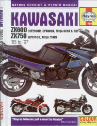
Руководство на английском языке по техническому обслуживанию и ремонту мотоциклов Kawasaki GPX600R/GPX750R/GPZ600R/Ninja 600R/Ninja 600RX/Ninja 750R/ZX600/ZX750 1985-1987 годов выпуска.
- Издательство: Haynes Publishing
- Год издания: 1999
- Страниц: 265
- Формат: PDF
- Размер: 77,0 Mb
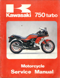
Руководство на английском языке по техническому обслуживанию и ремонту мотоциклов Kawasaki 750 turbo (GPZ 750 turbo).
- Издательство: Kawasaki Heavy Industries, Ltd.
- Год издания: 1983
- Страниц: 107
- Формат: PDF
- Размер: 25,0 Mb
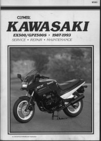
Руководство на английском языке по техническому обслуживанию и ремонту мотоциклов Kawasaki EX500 (GPZ500S) 1987-1993 годов выпуска.
- Издательство: Clymer
- Год издания: —
- Страниц: 225
- Формат: PDF
- Размер: 26,1 Mb
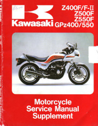
Руководство (дополнение) на английском языке по техническому обслуживанию и ремонту мотоциклов Kawasaki GPZ400/GPZ550/Z400F/Z400F-II/Z500F/Z550F.
- Издательство: Kawasaki Heavy Industries, Ltd.
- Год издания: 1984
- Страниц: 126
- Формат: PDF
- Размер: 9,9 Mb

Руководство на немецком языке по техническому обслуживанию и ремонту мотоциклов Kawasaki GPZ500S с 1986 года выпуска.
- Издательство: —
- Год издания: —
- Страниц: 120
- Формат: PDF
- Размер: 10,5 Mb

Руководство на немецком языке по техническому обслуживанию и ремонту мотоциклов Kawasaki GPZ1000RX (ZX1000-A1).
- Издательство: Kawasaki Heavy Industries, Ltd.
- Год издания: —
- Страниц: 130
- Формат: PDF
- Размер: 20,8 Mb

Руководство на немецком языке по техническому обслуживанию и ремонту мотоциклов Kawasaki GPZ1100 (ZX1100E).
- Издательство: Kawasaki Heavy Industries, Ltd.
- Год издания: —
- Страниц: 327
- Формат: PDF
- Размер: 10,9 Mb


Chapter One
General Information
Chapter Two
Troubleshooting
Chapter Three
Periodic Maintenance, Lubrication and Tune-up
Chapter Four
Engine
Chapter Five
Clutch
Chapter Six
Transmission
Chapter Seven
Fuel and Exhaust
Chapter Eight
Electrical Systems
Chapter Nine
Wheels, Tires and Brakes
Chapter Ten
Chassis
Supplement 1982 and Later Service lnformation
Index
Wiring Diagrams
CONTENTS
|
QUICK REFERENCE DATA |
………………………………………………………………………………….. XI |
|
CHAPTER ONE |
|
|
GENERAL INFORMATION |
………………………………………………………………………………………..1 |
|
Manual organization |
Shop tools |
|
Service hints |
Emergency tool kits |
|
Safety first |
Troubleshooting and tune — up |
|
Expendable supplies |
equipment |
|
CHAPTER TWO |
|
|
TROUBLESHOOTING ………………………………………………………………………………………………. |
9 |
Starting difficulties
Poor performance
Clutch and transmission
Drive train
Chassis
Brakes
CHAPTERTHREE LUBRICATION, MAINTENANCE
Battery
Engine oil and filter
General lubrication
Clutch adjustment
Drive chain
Swing arm
Steering
Front forks
Rear shock absorbers
Tires
Wheel bearing lubrication
Disc brake
Drum brake
Engine tune-up
Electrical system
Charging system
Lighting
Fuses
Wiring
|
AND TUNE-UP ……………………………………………………….. |
33 |
Air filter
Nuts, bolts and fasteners Fuel system
Spark plugs
Air suction valves (U.S. models) Valve clearance
Contact breaker points Ignition timing
(Contact point ignition) Ignition timing
(Transistorized ignition) Carburetor
Cylinder compression Storage
|
CHAPTER FOUR |
|
|
ENGINE ………………………………………………………………………………………………………………… |
70 |
Tools
Engine design Break-in
Servicing engine in frame Cam chain and tensioner Valve cover
Camshaft Cylinder head Valves and guides Cylinder block Pistons and rings
Oil cooler Removal/installation Oil filter bypass valve Oil pump
Crankcase
Secondary shaft and starter clutch Crankshaft and connecting rods Cam chain inspection
Primary chain inspection Crankcase assembly
|
CHAPTER FIVE |
|
|
CLUTCH ……………………………………………………………………………………………………………. |
124 |
|
Operation |
Clutch |
|
Clutch release mechanism |
|
|
CHAPTER SIX |
|
|
TRANSMlSSlON ………………………………………………………………………………………………. |
133 |
|
Sprocket cover |
Shift detent |
|
Neutral switch |
Transmission |
|
Engine sprocket |
Shift drum and forks |
|
Shift linkage |
Transmission gears |
|
CHAPTERSEVEN |
|
|
FUEL AND EXHAUST SYSTEMS ……………………………………………………………………….. |
148 |
|
Carburetor operation |
Fast idle adjustment |
|
Carburetor troubleshooting |
Crankcase breather |
|
Rejetting |
Air suction system |
|
Carburetor tuning |
(U.S. models) |
|
Carburetor service |
Fuel tank |
|
Fuel level inspection |
Fuel tap |
|
Idle mixture adjustment |
Fuel level sending unit |
|
(Non-U.S. models) |
Exhaust system |
|
CHAPTER EIGHT |
|
|
ELECTRICAL SYSTEM ………………………………………………………………………………………… |
169 |
|
Wiring diagrams |
Alternator stator |
|
Fuses |
Alternator rotor |
|
Battery |
Starting system |
|
Ignition system |
Starter motor |
|
Contact breaker points and |
Starter clutch |
|
condenser service |
Starter solenoid |
|
Spark plugs |
Lighting system |
|
Ignition advance mechanism |
Turn signal cancelling system |
|
Ignition coil |
Fuel level sensor |
|
Pickup coils |
Fuel gauge |
|
(Transistorized ignition) |
Horn |
|
CHAPTER NINE |
|
|
WHEELS, TIRES AND BRAKES ………………. |
…………………………………….192 |
|
Wheels |
Brake fluid change |
|
Front wheel |
Brake line replacement |
|
Speedometer gear lubrication |
Disc brake pad replacement |
|
Rear wheel |
Disc brake calipers |
|
Wheel bearings and seals |
Master cylinder rebuilding |
|
Tubeless tires |
Front master cylinder |
|
Brakes |
Rear master cylinder |
|
Hydraulic disc brakes |
Brake discs |
|
Brake system bleeding |
Drum brake |
|
CHAPTERTEN |
|
|
CHASSIS ……………………………………………………………………………………………………………. |
228 |
|
Fairing |
Rear shock |
|
Front forks |
Swing arm |
|
Steering head |
Drive chain |
|
SUPPLEMENT |
|
|
1982 AND LATER SERVICE INFORMATION …………………………………………………….. |
246 |
|
INDEX ………………………………………………………………………………………………………. |
307 |
|
WIRING DIAGRAMS ………………...……………………………………………………. |
End Of Book |
CYLINDER HEAD
TORQUE
SEQUENCE
|
TIRES AND TIRE PRESSURE |
||||
|
ModellTire size |
Pressure @ l o a d |
|||
|
0.215 |
Ib. |
Over 21 5 Ib. |
||
|
(0.97.5 |
kg) |
(Over 97.5 kg) |
||
|
KZ500-01, 02, KZ550-A1 (tube-type) |
||||
|
Front-3.25H-19 4PR |
28 psi (200 kPa) |
28 psi (200 kPa) |
||
|
Rear-3.75-18 4PR |
36 psi (245 kPa) |
40 psi (280 kPa) |
||
|
KZ500-03, KZ550-A2,B2,Dl |
(tubeless) |
|||
|
Front-3.25H-19 4PR |
28 psi (200 kPa) |
28 psi (200 kPa) |
||
|
Rear-3.75H-18 4PR |
32 psi (225 kPa) |
40 psi (280 kPa) |
||
|
KZ550-C1, C2 (tubeless) |
||||
|
Front-3.25s-19 4PR |
25 psi (175 kPa) |
25 psi (175 kPa) |
||
|
Rear-130/90-16 |
67H PR |
21 psi (150 kPa) |
28 psi (200 kPa) |
|
|
KZ550-HI (tubeless) |
See tire data decal |
|||
|
Front-3.25H-19 4PR |
||||
|
Rear-4.00-18 4PR |
||||
|
KZ550-F1, M l (tubeless) |
25 psi (175 kpa) |
25 psi (175 kPa) |
||
|
Front-100190-19 57s |
||||
|
Rear-130190.16 |
67s |
21 psi (147 kPa) |
28 psi (196 kPa) |
|
|
ZX550-A1, A2 (tubeless) |
28 psi (196 kPa) |
28 psi (196 kPa) |
||
|
Front-100190-18 56H |
||||
|
Rear-120180-18 |
62H |
32 psi (225 kPa) |
36 psi (245 kPa) |
|
TUNE.UP |
SPECIFICATIONS |
|
0.024-0.028 in. (0.6-0.7 mm) |
|
|
1979-1981; 1982-on US. |
NGK D8EA; ND X24ES-U |
|
1982-on non-US. |
NGK D8ES; ND X24ESR-0 |
|
Valve clearance (cold) |
0.004-0.008 in. (0.10-0.20 mm) |
|
0.006-0.010 in. (0.15-0.25 mm) |
|
|
1,150-1,250 rpm |
|
|
All other models |
1,000-1,100 rpm |
|
X |
FASTENERTORQUES
|
ft..lb. |
mkf4 |
|
|
Alternator rotor bolt |
||
|
Camshaft cap bolts |
||
|
Clutch hub nut |
||
|
Connecting rod cap nuts |
||
|
Crankcase bolts |
||
|
Small |
||
|
Large |
||
|
Cylinder base nuts |
||
|
Cylinder head |
||
|
Bolts |
||
|
Nuts |
||
|
Engine mounting bolts |
||
|
KZ550-HI, F1, M I |
||
|
All others |
||
|
Engine mounting bracket |
||
|
bolts |
||
|
Engine sprocket plate |
||
|
bolts |
||
|
Oil drain plug |
||
|
Except KZ550-F1, M I |
||
|
KZ550-F1, -M1 |
||
|
Oil filter mounting bolt |
||
|
Secondary shaft nut |
||
|
Spark plugs |
10 |
1.4 |
|
Chassis |
||
|
Front axle nut |
||
|
KZ550-F1, M I |
47 |
6.5 |
|
All others |
58 |
8.0 |
|
Front axle pinch bolt |
14.5 |
2.0 |
|
Front fork clamp bolts |
||
|
KZ550-F1, M I |
||
|
Upper |
15 |
2.1 |
|
Lower |
20 |
2.8 |
|
All other models |
13 |
1.8 |
|
Rear axle nut |
||
|
KZ550-F1, M1 |
54 |
7.5 |
|
2×550-At, A2 |
69 |
9.5 |
|
All others |
60 |
8.0 |
|
Steering stem head bolt |
||
|
KZ550bH1, F1, M1 |
31 |
4.3 |
|
All other models |
35 |
4.5 |
|
Swing arm pivot shaft |
||
|
KZ550-H1 |
58 |
8.0 |
|
KZ550-F1, M1 |
9.5 |
1.3 |
|
ZX550-A1, A2 |
65 |
90 |
Engine oil
Front fork oil
Fuel
Final drive gear oil
LUBRICANTS AND FUEL
SAE 10W-40, 1OW-50, 20W-40, 20W-50, rated SE or higher SAE 5W20
87 pump octane (RON ~tMON)/2
91 research octane (RON)
API GL-5 Hypoid gear oil; SAE 80 or SAE 90
|
FORK AIR PRESSURE* |
|||
|
Model |
Standard |
Range |
|
|
KZ550-C |
8.5 |
psi (60 kPa) |
7-10 psi (50-70 kPa) |
|
KZ550 |
|||
|
F1, M I |
7.5 |
psi (59 kPa) |
7-10 psi (49-69 kPa) |
|
H1 |
10.0 |
psi (70 kPa) |
8.5-1 1 psi (60-80 kPa) |
|
All others |
10 psi (70 kPa) |
8.5-1 1 psi (60-80 kPa) |
Never exceed 36 psi (245 k Pa) air pressure as it will damage the oil seals.
|
REAR SHOCK AIR PRESSURE* |
||
|
Model |
Standard |
Range |
|
KZ550 |
||
|
F1 |
11 psi (78 kPa) |
11-10 psi (78-147 kPa) |
Never exceed 71 psi (490 kPa) air pressure as it will damage the oil seals.
|
STANDARD FORK OIL* (1982-on) |
|||||
|
Model |
Dry capacity |
Wet capacity |
Oil level |
||
|
U.S. fl. oz. (cc) |
U.S. fl. ox. (CC) |
in. (mm) |
|||
|
KZ550-HI |
7.9 t 0.1 |
7.2 |
19.8 |
+O.l |
|
|
(234 |
k2.5) |
(215) |
(503 |
1 2 ) |
|
|
KZ550-F1, M I |
11.05 |
k0.15 |
9.4 |
16.3 |
+0.1 |
|
(327 |
+4) |
(280) |
(416 |
+2) |
|
|
ZX550-A1, A2 |
7.7 k0.08 |
*. |
18.58 |
t O . l |
|
|
(229 22.5) |
472 ( k 2) |
Fork oil level is checked with forks fully extended and the fork spring removed. Use oil grade SAE 5W-20. ‘Not specified.
XI1
This detailed, comprehensive manual covers Kawasaki KZ500/550 and ZX550 models. The expert text gives complete information on maintenance, repair and overhaul. Hundreds of photos and drawings guide you through every step. The book includes all you need to know to keep your bike running right.
Chapters One through Ten contain general information on all models and specific information on 1979-198 1 models. The Supplement at the end of the book contains information on 1982 and later models that differ from earlier years. Where repairs are practical for the owner/mechanic, complete procedures are given. Equally important, difficult jobs are pointed out. Such operations are usually more economically performed by a dealer or independent garage.
A shop manual is a reference. You want to be able to find information fast. As in all Clymer books, this one is designed with this in mind. All chapters are thumb tabbed. Important items are indexed at the end of the book. All the most frequently used specifications and capacities are summarized on the Quick Reference pages at the beginning of the book.
Keep the book handy. It will help you to better understand your Kawasaki, lower repair and maintenance costs and generally improve your satisfaction with your bike.
C H A P T E R O N E
GENERAL INFORMATION
The troubleshooting, maintenance, tune-up, and step-by-step repair procedures in this book are written specifically for the owner and home mechanic. The text is accompanied by helpful photos and diagrams to make the job as clear and correct as possible.
Troubleshooting, maintenance, tune-up, and repair are not difficult if you know what to d o and what tools and equipment to use. Anyone of average intelligence, with some mechanical ability, and not afraid to get their hands dirty can perform most of the procedures in this book.
In some cases, a repair job may require tools or skills not reasonably expected of the home mechanic. These procedures are noted in each chapter and i t is recommended that you take the job to your dealer, a competent mechanic, or a machine shop.
M A N U A L ORGANIZATION
This chapter provides general information, safety and service hints. Also included are lists of recommended shop and emergency tools as well as a brief description of troubleshooting and tune-up equipment.
Chapter Two provides methods and suggestions for quick and accurate diagnosis and
repair of problems. Troubleshooting procedures discuss typical symptoms and logical methods to pinpoint the trouble.
Chapter Three explains all periodic lubrication and routine maintenance necessary to keep your motorcycle running well. Chapter Three also includes recommended tune-up procedures, eliminating the need to constantly consult chapters o n the various subassemblies.
Subsequent chapters cover specific systems such as the engine, transmission, and electrical system. Each of these chapters provides disassembly, inspection, repair, and assembly procedures in a simple step-by-step format. If a repair is impractical for the home mechanic i t is indicated. In these cases it is usually faster and less expensive to have the repairs made by a dealer o r competent repair shop. Essential specifications are included in the appropriate chapters.
When special tools are required to perform a task included in this manual, the tools are il- lustrated. I t may be possible to borrow or rent these tools. T h e inventive mechanic may also be able t o find a suitable substitute in his tool box, o r t o fabricate one.
The terms NOTE, C A U T I O N , and W A R N I N G have specific meanings in this manual. A NOTE provides additional o r explanatory information. A
CAUTION is used to emphasize areas where equipment damage could result if proper precautions are not taken. A W A R N I N G is used to stress those areas where personal injury or death could result from negligence, in addition to possible mechanical damage.
SERVICE HINTS
Time, effort, and frustration will be saved and possible injury will be prevented if you observe the following practices.
Most of the service procedures covered are straightforward and can be performed by anyone reasonably handy with tools. It is suggested, however, that you consider your own capabilities carefully before attempting any operation involving major disassembly of the engine.
Some operations, for example, require the use of a press. It would be wiser to have these performed by a shop equipped for such work, rather than to try t o d o the job yourself with makeshift equipment. Other procedures require precision measurements. Unless you have the skills and equipment required, it would be better to have a qualified repair shop make the measurements for you.
Repairs go much faster and easier if the parts that will be worked on are clean before you begin. There are special cleaners for washing the engine and related parts. Brush or spray on the cleaning solution, let stand, then rinse it away with a garden hose. Clean all oily or greasy parts with cleaning solvent as you remove them.
W A R N I N G
Never use gasoline as a cleaning agent. It presents an extreme fire hazard. Be sure to work in a well-ventilated area when using cleaning solvent. Keep a fire extinguisher, rated for gasoline fires, handy in any case.
Much of the labor charge for repairs made by dealers is for the removal and disassembly of other parts to reach the defective unit. It is frequently possible to perform the preliminary operations yourself and then take the defective unit in to the dealer for repair, at considerable savings.
Once you have decided to tackle the job yourself, make sure you locate the appropriate section in this manual, and read it entirely. Study the illustrations and text until you have a good idea of what is involved in completing the job satisfactorily. If special tools are required, make arrangements to get them before you start. Also, purchase any known defective parts prior to starting on the procedure. It is frustrating and time-consuming to get partially into a job and then be unable to complete it.
Simple wiring checks can be easily made at home, but knowledge of electronics is almost a necessity for performing tests with complicated electronic testing gear.
During disassembly of parts keep a few general cautions in mind. Force is rarely needed to get things apart. If parts are a tight fit, like a bearing in a case, there is usually a tool designed to separate them. Never use a screwdriver to pry apart parts with machined surfaces such as cylinder head or crankcase halves. You will mar the surfaces and end up with leaks.
Make diagrams wherever similar-appearing parts are found. You may think you can remember where everything came from — but mistakes are costly. There is also the possibility you may get sidetracked and not return to work for days o r even weeks — in which interval, carefully laid out parts may have become disturbed.
Tag all similar internal parts for location, and mark all mating parts for position. Record number and thickness of any shims as they are removed. Small parts such as bolts can be identified by placing them in plastic sandwich bags that are sealed and labeled with masking tape.
Wiring should be tagged with masking tape and marked as each wire is removed. Again, do not rely o n memory alone.
Disconnect battery ground cable before working near electrical connections and before disconnecting wires. Never run the engine with the battery disconnected; the alternator could be seriously damaged.
Protect finished surfaces from physical damage or corrosion. Keep gasoline and brake fluid off painted surfaces.
Frozen or very tight bolts an d screws can often be loosened by soaking with penetrating oil like Liquid Wrench o r WD-40, then sharply striking the bolt head a few times with a hammer and punch (or screwdriver for screws). Avoid heat unless absolutely necessary, since it may melt, warp, or remove the temper from many parts.
Avoid flames or sparks when working near a charging battery or flammable liquids, such as gasoline.
No parts, except those assembled with a press fit, require unusual force during assembly. If a part is hard to remove or install, find out why before proceeding.
Cover all openings after removing parts t o keep dirt, small tools, etc., from falling in.
When assembling two parts, start all fasteners, then tighten evenly.
Wiring connections and brake shoes, drums, pads, and discs and contact surfaces in dry clutches should be kept clean an d free of grease and oil.
When assembling parts, be sure all shims an d washers are replaced exactly as they came out.
Whenever a rotating part butts against a stationary part, look for a shim o r washer. Use new gaskets if there is any doubt about the condition of old ones. Generally, you should apply gasket cement to one mating surface only, so the parts may be easily disassembled in the future. A thin coat of oil o n gaskets helps them seal effectively.
Heavy grease can be used t o hold small parts in place if they tend to fall out during assembly. However, keep grease and oil away from electrical, clutch, and brake components.
High spots may be sanded off a piston with sandpaper, but emery cloth an d oil d o a much more professional job.
Carburetors are best cleaned by disassembling them and soaking the parts in a commercial carburetor cleaner. Never soak gaskets and rubber parts in these cleaners. Never use wire to clean out jets and air passages; they are easily damaged. Use compressed air t o blow out the carburetor, but only if the float has been removed first.
Take your time and d o the job right. D o not forget that a newly rebuilt engine must be
broken in the same as a new one. Refer to your owner’s manual for the proper break-in procedures.
SAFETY FIRST
Professional mechanics can work for years and never sustain a serious injury. If you observe a few rules of common sense and safety, you can enjoy many safe hours servicing your motorcycle. You could hurt yourself or damage the motorcycle if you ignore these rules.
1. Never use gasoline a s a cleaning solvent.
2. Never smoke o r use a torch in the vicinity of flammable liquids such as cleaning solvent in open containers.
3. Never smoke o r use a torch in a n area where batteries ar e being charged. Highly explosive hydrogen gas is formed during the charging process.
4. Use the proper sized wrenches to avoid damage t o nuts a n d injury to yourself.
5.When loosening a tight or stuck nut, be guided by what would happen if the wrench should slip. Protect yourself accordingly.
6.Keep your work area clean an d uncluttered.
7. Wear safety goggles during all operations involving drilling, grinding, o r use of a cold chisel.
8. Never use worn tools.
9. Keep a fire extinguisher handy and be sure it is rated for gasoline (Class B) and electrical (Class C) fires.
EXPENDABLE SUPPLIES
Certain expendable supplies are necessary. These include grease, oil, gasket cement, wiping rags, cleaning solvent, and distilled water. Also, special locking compounds, silicone lubricants, an d engine an d carburetor cleaners may be useful. Cleaning solvent is available at most service stations an d distilled water for the battery is available at supermarkets.
SHOP TOOLS
For complete servicing and repair you will need a n assortment of ordinary hand tools
(Figure 1).
4
As a minimum, these include:
Combination wrenches
Sockets
Plastic mallet
Small hammer
Impact driver
Snap ring pliers
Gas pliers
Phillips screwdrivers
Slot (common) screwdrivers
Feeler gauges
Spark plug gauge
Spark plug wrench
Special tools required are shown in the chapters covering the particular repair in which they are used.
Engine tune-up a n d troubleshooting procedures require other special tools and equipment. These are described in detail in the following sections.
EMERGENCY TOOL KITS
Highway
A small emergency tool kit kept on the bike is handy for road emergencies which otherwise
CHAPTER ONE
could leave you stranded. The tools and spares listed below a n d shown in Figure 2 will let you handle most roadside repairs.
a. Motorcycle tool kit (original equipment)
b.Impact driver
c.Silver waterproof sealing tape (duct tape) d. H o s e d a m p s (3 sizes)
e. Silicone sealer f. Lock ‘ N ‘ Seal g. Flashlight
h. Tire patch kit i. Tire irons
j. Plastic pint bottle (for oil)
k.Waterless hand cleaner
1.Rags for clean u p
Off-Road
A few simple tools and aids carried on the motorcycle can mean the difference between walking or riding back to camp or to where repairs can be made. See Figure 3.
A few essential spare parts carried in your truck o r van can prevent a day or weekend of trail riding from being spoiled. See Figure 4.
GENERAL INFORMATION
On the Motorcycle
a. Motorcycle tool kit (original equipment)
b.Drive chain master link
c.Tow line
d. Spark plug
e.Spark plug wrench f. Shifter lever
g. Clutch/brake lever
h. Silver waterproof sealing tape (duct tape)
i. Loctite Lock ‘ N ‘ Seal
In the Truck
a.Control cables (throttle, clutch, brake)
b.Silicone sealer
c.Tire patch kit
d. Tire irons
e.Tire pump
f. Impact driver g. Oil
W A R N l N G
Tools and spares should be carried on the tnotorcycle — not i n clothing where a simple fall could result i n serious injury from a sharp tool.
5
TROUBLESHOOTING AND
TUNE-UP EQUIPMENT Voltmeter, Ohmmeter, and Ammeter
For testing the ignition or electrical system, a good voltmeter is required. For motorcycle use, an instrument covering 0-20 volts is satisfactory. One which also has a 0-2 volt scale is necessary for testing relays, points, or individual contacts where voltage drops are much smaller. Accuracy should be _+ X volt.
An ohmmeter measures electrical resistance. This instrument is useful for checking continuity (open and short circuits), and testing fuses and lights.
The ammeter measures electrical current. Ammeters for motorcycle use should cover 0-50 amperes and 0-250 amperes. These are useful for checking battery charging and starting current.
Several inexpensive vakl’s (volt-ohm-milli- ammeter) combine all three instruments into one which fits easily in any tool box. See Figure 5. However, the ammeter ranges are usually too small for motorcycle work.
Hydrometer
The hydrometer gives a useful indication of battery condition and charge by measuring the
specific gravity of the electrolyte in each cell. See Figure 6. Complete details on use and interpretation of readings are provided in the electrical chapter.
Compression Tester
The compression tester measures the compression pressure built up in each cylinder. The results, when properly interpreted, can indicate
general cylinder, ring, and valve condition. See Figure 7. Extension lines are available for hard- to-reach cylinders.
Dwell Meter (Contact Breaker
Point Ignition Only)
A dwell meter measures the distance in degrees of cam rotation that the breaker points remain closed while the engine is running. Since
this angle is determined by breaker point gap, dwell angle is a n accurate indication of breaker point gap.
Many tachometers intended for tuning and testing incorporate a dwell meter as well. See Figure 8 . Follow the manufacturer’s instructions t o measure dwell.
Tachometer
A tachometer is necessary for tuning. See Figure 8 . Ignition timing and carburetor adjustments must be performed at the specified idle speed. T h e best instrument for this purpose is on e with a low range of 0-1,000 or 0-2,000 rpm for setting idle, and a high range of 0-4,000 or more for setting ignition timing at 3,000 rpm. Extended range (0-6,000 or 0-8,000 rpm) instruments lack accuracy at lower speeds. The instrument should be capable of detecting changes of 25 r p m o n the low range.
NOTE: The motorcycle’s tachometer is not accurate enough for correct idle adjustmen I.
Strobe Timing Light
This instrument is necessary for tuning, as i t permits very accurate ignition timing. The light flashes at precisely the same instant that No. 1 cylinder fires, at which time the timing marks o n the engine should align. Refer to Chapter Three for exact location of the timing marks for your engine.
II
Suitable lights range from inexpensive neon bulb types ($2-3) t o powerful xenon strobe lights ($20-40). See Figure 9. Neon timing lights are difficult to see and must be used in dimly l i t areas. Xenon strobe timing lights can be used outside in bright sunlight.
Tune-up Kits
Many manufacturers offer kits that combine several useful instruments. Some come in a convenient carry case and are usually less expensive than purchasing one instrument at a time. Figure 10 shows one of the kits that is available. The prices vary with the number of instruments included in the kit.
Manometer (Carburetor Synchronizer)
A manometer is essential for accurately synchronizing carburetors o n multi-cylinder engines. The instrument detects intake pressure differences between carburetors and permits them to be adjusted equally. A suitable manometer costs about $25 and comes with detailed instructions for use. See Figure 11.
Fire Extinguisher
A fire extinguisher is a necessity when working on a vehicle. It should be rated for both Class B (flammable liquids — gasoline, oil, paint, etc.) and Class C (electrical — wiring, etc.) type fires. I t should always be kept within reach. See Figure 12.
CHAPTER ONE
C H A P T E R T W O
TROUBLESHOOTING
Troubleshooting motorcycle problems is relatively simple. T o be effective and efficient, however, it must be done in a logical step-by- step manner. If it is not, a great deal of time may be wasted, good parts may be replaced unnecessarily, and the true problem may never be uncovered.
Always begin by defining the symptoms as closely as possible. Then, analyze the symptoms carefully so that you can make a n intelligent guess at the probable cause. Next, test the probable cause and attempt to verify it; if it’s not at fault, analyze the symptoms once again, this time eliminating the first probable cause. Continue on in this manner, a step at a time, until the problem is solved.
At first, this approach may seem t o be time consuming, but you will soon discover that it’s not nearly so wasteful as a hit-or-miss method that may never solve the problem. And just as important, the methodical approach to troubleshooting ensures that only those parts that are defective will be replaced.
The troubleshooting procedures in this chapter analyze typical symptoms a n d show logical methods for isolating and correcting trouble. They are not, however, the only methods; there may be several approaches to a given problem, but all good troubleshooting methods have one thing in common — a logical, systematic approach.
ENGIN E
The entire engine must be considered when trouble arises that is experienced as poor performance o r failure to start. The engine is more than a combustion chamber, piston, and crankshaft; it also includes a fuel delivery system, a n ignition system, and an exhaust system.
Before beginning t o troubleshoot any engine problems, it’s important to understand an engine’s operating requirements. First, it must have a correctly metered mixture of gasoline and air (Figure 1). Second, it must have an airtight combustion chamber in which the mixture can be compressed. And finally, it requires a precisely timed spark to ignite the compressed mixture. If one o r more is missing, the engine won’t run, and if just one is deficient, the engine will run poorly at best.
Of the three requirements, the precisely timed spark — provided by the ignition system — is most likely t o be the culprit, with gadair mixture (carburetion) second, and poor compression the least likely.
STARTING DIFFICULTIES
Hard starting is probably the most common motorcycle ailment, with a wide range of problems likely. Before delving into a reluctant or non-starter, first determine, what has changed
4-STROKE OPERATING PRINCIPLES
TROUBLESHOOTING
since the motorcycle last started easily. For instance, was the weather dry then and is it wet now? Has the motorcycle been sitting in the garage for a long time? Ha s it been ridden many miles since it was last fueled?
Has starting become increasingly more difficult? This alone could indicate a number of things that may be wrong but is usually associated with normal wear of ignition an d engine components.
While it’s not always possible t o diagnose trouble simply from a change of conditions, this information can be helpful and at some future time may uncover a recurring problem.
Fuel Delivery
Although it is the second most likely cause of trouble, fuel delivery should be checked first simply because it is the easiest.
First, check the tank t o make sure there is fuel in it. Then, disconnect the fuel hose at the carburetor, open the valve and check for flow (Figure 2). If fuel does not flow freely make sure the tank vent is clear. Next, check for blockage in the line o r valve. Remove the valve and clean it as described in the fuel system chapter.
If fuel flows from the’hose, reconnect it an d remove the float bowl from the carburetor, open the valve and check for flow through the float needle valve. If it does not flow freely when the float is extended and then shut off when the flow is gently raised, clean the carburetor as described in the fuel system chapter.
When fuel delivery is satisfactory, go on to the ignition system.
Ignition
Remove the spark plug from the cylinder an d check its condition. The appearance of the plug is a good indication of what’s happening in the combustion chamber; for instance, if the plug is wet with gas, it’s likely that engine is flooded. Compare the spark plug t o Figure 3. Make certain the spark plug heat range is correct. A «cold» plug makes starting difficult.
After checking the spark plug, reconnect it t o the high-tension lead and lay it o n the cylinder head so it makes good contact (Figure 4). Then,
11
with the ignition switched o n , crank the engine several times and watch for a spark across the plug electrodes. A fat, blue spark should be visible. If there is n o spark, or if the spark is weak, substitute a good plug for the old one and check again. If the spark has improved, the old plug is faulty. If there was no change, keep looking.
Make sure the ignition switch is not shorted t o ground. Remove the spark plug cap from the end of the high-tension lead and hold the exposed end of the lead about )/8 inch from the cylinder head. Crank the engine and watch for a spark arcing from the lead to the head. If it’s satisfactory, the connection between the lead and the cap was faulty. If the spark hasn’t improved, check the coil wire connections.
If the spark is still weak, remove the ignition cover an d remove any dirt o r moisture from’the points o r sensor. Check the point or air gap against the specifications in the Quick Reference Data at the beginning of the book.
If spark is. still not satisfactory, a more serious problem exists than can be corrected with simple adjustments. Refer to the electrical system chapter for detailed information for correcting major ignition problems.
Compression
Compression — o r the lack of it — is the least likely cause of starting trouble. However, if compression is unsatisfactory, more than a simple adjustment is required to correct it (see the engine chapter).
A n accurate compression check reveals a lot about the condition of the engine. T o perform this test you need a compression gauge (see Chapter One). Th e engine should be at operating temperature for a fully accurate test, but even a cold test will reveal if the starting problem is compression.
Remove the spark plug and screw in a compression gauge (Figure 5). With assistance, hold the throttle wide open an d crank the engine several times, until the gauge ceases to rise. Normal compression should be 130-160psi, but a reading as low as 100 psi is usually sufficient for the engine t o start. If the reading is much lower than normal, remove the gauge and pour about a tablespoon of oil into the cylinder.
— Melted ground
TROUBLESHOOTING
w
lORMAL
Appearance-Firing tip has deios~tsof light gray to light tan
Can be cleaned, regapped and eused
:ARBON FOULED
|
Appearance-Dull |
dry black w ~ t h |
||||||
|
luffy |
carbon |
depos~tson the i n |
|||||
|
ulator |
tip |
electrode and exposed |
|||||
|
hell |
|||||||
|
Caused by-Fuellair |
m ~ x t u r etoo |
||||||
|
c h |
plug |
heat range |
too |
cold |
|||
|
teak |
ignition |
system |
dirty |
air |
|||
|
leaner |
faulty |
automatic |
choke or |
||||
|
xcesslve Idling |
|||||||
|
Can |
be |
cleaned |
regapped |
and |
|||
|
eused |
31L FOULED
Appearance-Wet black depos~ts
|
I n insulator and exposed shell |
|||||
|
Caused |
by-Excessive |
oil |
enter- |
||
|
n g |
the |
combust~on |
chamber |
||
|
hrough worn rlngs |
pistons |
valve |
|||
|
g d e s or bear~ngs |
|||||
|
1 Replace |
with |
new |
plugs |
(use |
a |
|
latter |
plug if |
engine |
18 not |
re |
)aired)
LEAD FOULED
Appearance — Yellow m u l a t o r deposits (may sometimes be dark
|
gray black or tan in |
color) on the |
|
insulator t ~ p |
|
|
Caused by-Highly |
leaded gaso- |
|
lhne |
Replace with new plugs
LEAD FOULED
Appearance-Yellow glazed depos~tsi n d c a t ~ n gmelted lead deposits due to hard acceleration
Caused by-Highly leaded gas@ line
Replace with new plugs
13
OIL AND LEAD FOULED
Appearance-Glazed yellow de pos~t sw ~ t ha sl~gh tbrown~shtint on th e insulator tip and ground electrode
Replace with new plugs
FUEL ADDITIVE RESIDUE
Appearance — Brown colored hardened ash deposits on the insu lator t ~ anpd ground electrode
Caused by-Fuel andlor oil addi- t ~ v e s
Replace w ~ t hnew plugs
WORN
Appearance — Severely worn or eroded electrodes
Caused by-Normal wear or unusual 011andlo r fuel add~tives
Replace w ~ t hnew plugs
PREIGNITION
Appearance
|
electrode |
||
|
Caused |
by-Overadvanced |
ignl |
|
tion timing inoperative |
ignhtion |
advance mechanism too low of a fuel octane rating lean fuellair m ~ x t u r eor carbon deposits in combustion chamber
PREIGNITION
|
Appearance-Melted |
center elec. |
|||
|
trade |
||||
|
Caused |
by-Abnormal |
combus- |
||
|
tion due |
to overadvanced ignit~on |
|||
|
t i m ~ n gor |
~ncorrect advance |
too |
||
|
low of a |
fuel octane |
rating |
lean |
|
|
fuellair |
mixture |
or |
carbon |
de- |
|
posits In combustion chamber |
||||
|
Correct |
engine |
problem |
and |
|
|
replace with new plugs |
INCORRECT HEAT RANGE
Appearance-Melted center electrode and white blistered ~nsulator
t i p
Caused by-Incorrect plug heat range select~on
Replace w ~ t hnew plugs
|
IGNITION: |
Turn switches on. Remove spark plug |
|
and check for spark outside cyiinder |
t
Refer to electrical chapter for correction
Refer to engine chepter for correction
Crank the engine several times to distribute the oil and test the compression once again. If i t is now significantly higher, the rings and bore are worn. If the compression did not change, the valves are not seating correctly. Adjust the valves and check again. If the compression is still low, refer t o the engine chapter.
NOTE: L o w compression indicates a developing problem. The condition causing it should be corrected as soon as possible.
POOR PERFORMANCE
Poor engine performance can be caused by any of a number of things related to carburetion, ignition, and the condition of the sliding and rotating components in the engine. In addition, components such as brakes, clutch, and transmission can cause problems that seem to be related t o engine performance, even when the engine is in to p running condition.
Poor Idling
Idling that is erratic, too high, or too low is most often caused by incorrect adjustment of the carburetor idle circuit. Also, a dirty air filter o r a n obstructed fuel tank vent can affect idle speed. Incorrect ignition timing or worn or faulty ignition components are also good possibilities.
First, make sure the air filter is clean and correctly installed. Then, adjust the throttle cable free play, the throttle stop screw, and the idle mixture air screw (Figure 6) a s described in the routine maintenance chapter.
If idling is still poor, check the carburetor and manifold mounts for leaks; with the engine warmed u p and running, spray WD-40 or a similar light lube aroun d the flanges and joints of the carburetor an d manifold (Figure 7). Listen for changes in engine speed. If a leak is present, the idle speed will drop as the lube «plugs» the leak an d then pick u p again as i t is drawn into the engine. Tighten the nuts and clamps and test again. If a leak persists, check for a damaged gasket o r a pinhole in the manifold. Minor leaks in manifold hoses can be repaired with silicone sealer, but if cracks or holes are extensive, the manifold should be replaced.
16
A worn throttle slide may cause erratic running and idling, but this is likely only after many thousands of miles of use. T o check, remove the carburetor top and feel for back and forth movement of the slide in the bore; it should be barely perceptible. Inspect the slide for large worn areas and replace it if it is less than perfect (Figure 8).
If the fuel system is satisfactory, check ignition timing and breaker point ga p (air gap in electronic ignition). Check the condition of the system components as well. Ignition-caused idling problems such as erratic running can be the fault of marginal components. See the electrical system chapter for appropriate tests.
Rough Running or Misfiring
Misfiring (see Figure 9) is usually caused by an ignition problem. First, check all ignition connections (Figure 10). They should be clean, dry, and tight. Don’t forget the kill switch; a loose connection can create a n intermittent short.
CHAPTER TWO
|
ENGINE RUNS ROUGH AND MISFIRES |
0— |
|
ENGINE M I S S E S A L L SPEEDS |
f Check ignition wire connections.
+Inspect the insulation on the spark plug high. tension lead for cracking and deterioration.
+Inspect the spark plug for correct heat range and condition.
|
+Check |
the point gap and the spring tension on |
|
the contact breaker or check electronic module |
|
|
on models with electronic ignition. |
|
|
ENGINE MISSES AT LOW SPEED |
|
|
+Check |
ignition system (above). |
|
+Clean |
carburetor-pay particular attention to |
|
low-speed jet and circuit. |
|
|
ENGINE MISSES AT MID-RANGE |
|
|
+Check |
i g n ~ t ~ osystemn (above). |
|
+Clean |
carburetor. |
+Check pos~tionand cond~tion of slide needle. -.+
Handlebar (kill) switch
Main switch
AT HIG H SPEED
Check the insulation on the high-tension spark plug lead. If it is cracked or deteriorated it will allow the spark to short t o ground when the engine is revved. This is easily seen at night. If arcing occurs, hold the affected area of the wire away from the metal t o which it is arcing, using an insulated screwdriver (Figure ll),and see if the misfiring ceases. If it does, replace the high-tension lead. Also check the connection of the spark plug cap to the lead. If it is poor, the spark will break down at this point when the engine speed is increased.
The spark plug could also be poor. Test the system with a new plug.
Incorrect point gap or a weak contact breaker spring can cause misfiring. Check the gap and the alignment of the points. Push the
moveable arm back and check for spring ten-
‘
sion (Figure 12). It should feel stiff.
On models with electronic ignition, have the electronic module tested by a dealer or substitute a known good unit for a suspected one.
If misfiring occurs only at a certain point in engine speed, the problem may very likely be
V
LOSS OF POWER
Handlebar (kill) switch
Main switch W
Check ignition and carburetion and tune engine if necessary.
Check compression. If compression rises following wet test, ring and cylinder wear is indicated. If compression remains low during wet test, valve and seat wear are indicated.
Check brake adjustment and condition; they may be dragging.
Check wheel bearings for dirt, dryness, and wear that may create drag.
module
Sudden
Check compression (above). If power loss is sudden, damage to rings, piston, and bore or valves and seats are more likely than wear.
Check the ignition system for a failed component, poor contact, or change in timing or point gap. Check electronic module on electronic ignition.
Check the fuel system for an obstruction.
carburetion. Poor performance at idle is described earlier. Misfiring at low speed (just above idle) can be caused by a dirty low-speed circuit or jet (Figure 13). Poor midrange performance is attributable to a worn or incorrectly adjusted needle and needle jet. Misfiring at high speed (if not ignition related) is usually caused by a too-large main jet which causes the engine to run rich. Any of these carburetorrelated conditions can be corrected by first cleaning the carburetor and then adjusting i t as
described in the tune-up and maintenance chapter.
Loss of Power
First determine how the power loss developed (Figure 14). Did it decline over a long period of time or did it d r o p abruptly? A gradual loss is normal, caused by deterioration of the engine’s state of tune and the normal wear of the cylinder and piston rings and the valves and seats. In such case, check the condition of the
|
TROUBLESHOOTING |
21 |
||
|
ignition a n d carburetio n and mcakure the com — |
|||
|
pression a s described earlier. |
|||
|
A sudde n powe r loss ma y be caused by n |
|||
|
failed ignition |
c o m p o n e n t , obstruction in |
the |
|
|
fuel system, d a m a g e d \ , a l ~oer seat. or a broken |
|||
|
piston ring o r d a m a g e d piston (Figure 15). |
|||
|
If t he engine is in g o o d shap e and tone, check |
|||
|
th e brak e a d j u s t m e n t . If the brakes are drag- |
|||
|
ging, they will c o n s u m e considerable po\\er. |
|||
|
Also check t h e wheel bearings. If they are dry, |
|||
|
extremely dirty , o r badly wor n they can create |
|||
|
considerable d r a g . |
|||
|
A m o d e r n motorcycle engine, in good |
|||
|
mechanical condition , correctly tuned, and |
|||
|
operate d a s i t |
wa s intended , will rarely |
ex- |
|
|
perience o ~ e r h e a t i n pproblems . H o w e ~ e r ,out- |
|||
|
of-spec condition s c a n create seler e o\erheat — |
|||
|
J |
ing that ma y result in teriou s engine damage. |
||
|
Refer t o Figure 16. |
22
Overheating is difficult t o detect unless i t is extreme, in which case it will usually be apparent as excessive heat radiating from the engine, accon~paniedby the smell of hot oil and sharp, snapping noises when the engine is first shut off and begins t o cool.
Unless the motorcycle is operated under sustained high load or is allowed t o idle for long periods of time, overheating is usually the result of an internal problem. Most often it’s caused by a too-lean fuel mixture.
Remove the spark plug and compare i t to Figure 3. If a too-lean condition is indicated, check for leaks in the intake manifold (see Poor Idling).The carburetor jetting may be incorrect but this is unlikely if the overheating problem has just developed (unless, of course, the engine was jetted for high altitude and is now being run near sea level). Check the slide needle in the carburetor to make sure i t hasn’t come loose and is restricting the flow of gas through the main jet and needle jet (Figure 17).
Check the ignition timing: extremes o f either advance or retard can cause overheating.
Piston Seizure and Damage
Piston seizure is a common result o f overheating (see above) because an aluminum piston expands at a greater rate than a steel cylinder. Seizure can also be caused by piston- to-cylinder clearance that is too small; ring end gap that is too small; insufficient oil: spark plug heat range too hot; and broken piston ring or ring land.
A major piston seizure can cause severe engine damage. A minor seizure — which usually subsides after the engine has cooled a few minutes — rarely does more than scuff the piston skirt the first time it occurs. Fortunately, this condition can be corrected by dressing the piston with crocus cloth, refitting the piston and rings to the bore with recommended clearances, and checking the timing t o ensure overheating does not occur. Regard that first seizure as a warning and correct the problem before continuing t o run the engine.
CLUTCH A N D TRANSMISSION
|
1 . Clutch slips-Make |
sure lever free play is |
|
sufficient to allow the |
clutch t o fully engage |
CHAPTER TWO
Needle\ \
(Figure 18). Check the contact surfaces for wear and glazing. Transmission oil additives also can cause slippage in wet clutches. If slip occurs only under extreme load, check the condition of the springs or diaphragm and make sure the clutch bolts are snug and uniformly tightened.
|
2. Clutch drags-Make |
sure |
lever free play |
||
|
isn’t so great |
that i t |
fails to |
disengage |
the |
|
clutch. Check |
for warped plates or disc. I f |
the |
transmission oil (in wet clutch systems) is extremely dirty o r heavy, i t may inhibit the clutch
|
from releasing. |
|
|
3. Transmission shifts hard-Extremely |
dirty |
|
oil can cause the transmission to shift |
hard. |
|
TROUBLESHOOTING |
23 |
|
|
Check the selector shaft for |
bending |
(Fig- |
|
ure 19). Inspect the shifter and gearsets for |
||
|
wear an d damage. |
||
|
4. Transmission slips o u t of gear-This |
can be |
|
|
caused by worn engagement dogs or a worn or |
||
|
damaged shifter (Figure 20). The overshift |
||
|
travel o n the selector may be misadjusted. |
||
|
5. Transmission is noisy-Noises |
usually in- |
|
|
dicate the absence of lubrication or wear and |
damage t o gears, bearings, or shims. It’s a good idea t o disassemble the transmission and carefully inspect it when noise first occurs.
DRIVE TRAIN
Drive train problems (outlined in Figure 21) arise from normal wear and incorrect maintenance.
CHASSIS
Chassis problems ar e outlined in Figure 22.
I . Motorcycle pulls t o on e side-Check for loose suspension components, axles, steering
0
DRIVE SYSTEM
CLUTCH DRAGS
Adjust free play
CLUTCH SLIPS
Adjust free play —t
I
I Inspect plates for wear and
Check plates
TRANSMISSION SLIPS OUT OF GEAR
rRANSMlSSlON SHIFTS HARD
Check for bent selector shaft
:heck overshift travel and increase if i n s u f f i c i e q
TRANSMISSION IS NOISY
Check oil level
Inspect selector and gearsets for wear
SUSPENSION AND HANDLING CONTINUED
REAR SUSPENSION STICKS
Replace shock with bent rod
REAR SUSPENSION
WON’T DAMP
head, swing arm pivot. Check wheel alignment (Figure 23). Check for damage t o the frame a n d suspension components.
2. Front suspension doesn ‘t damp-This is most often caused by a lack of damping oil in the fork legs. If the upper fork tubes are exceptionally oily, it’s likely that the seals are worn out and should be replaced.
3 . Front suspension sticks o r won’t fully com- press-Misalignment of the forks when the wheel is installed can cause this. Loosen the axle nut and the pinch bolt o n the nut end of the axle (Figure 24). Lock the front wheel with the brake and compress the front suspension several times to align the fork legs. Then, tighten the pinch bolt a n d then the axle nut.
The trouble may also be caused by a bent o r dented fork slider (Figure 25). T h e distortion required to lock up a fork tube is s o slight that it is often impossible to visually detect. If this type of damage is suspected, remove the fork leg and remove the spring from it. Attempt to operate the fork leg. If it still binds, replace the
|
slider; it’s not practical t o repair it. |
|
|
4. Rear suspension does n o t damp-This |
is |
|
usually caused by damping oil leaking |
past |
30
worn seals. Rebuildable shocks should be refitted with complete service kits and fresh oil. Non-rebuildable units should be replaced.
5 . Rear suspension sticks-This is commonly caused by a bent shock absorber piston rod (Figure 26). Replace the shock; the rod can’t be satisfactorily straightened.
6. Steering is tight o r «notchy»-Steering head bearings may be dry, dirty, or worn. Adjustment of the steering head bearing pre-load may be too tight.
7 . Steering is sloppy-Steering head adjustment may be too loose. Also check the swing arm pivot; looseness or extreme wear at this point translate t o the steering.
BRAKES
Brake problems arise from wear, lack of maintenance, and from sustained or repeated
|
exposure to dirt and water. |
|
|
1 . Brakes are ineffective-Ineffective |
brakes |
are most likely caused by incorrect adjustment. If adjustment will not correct the problem, remove the wheels and check for worn or glazed linings. If the linings are worn beyond the service limit, replace them. If they are simply glazed, rough them u p with light sandpaper.
In hydraulic brake systems, low fluid levels can cause a loss of braking effectiveness, as can worn brake cylinder pistons and bores. Also check the pads to see if they are worn beyond the service limit.
2. Brakes lock o r drag-This may be caused by incorrect adjustment. Check also for foreign matter embedded in the lining a n d for dirty and dry wheel bearings.
ELECTRICAL SYSTEM
Many electrical system problems can be easily solved by ensuring that the affected connections are clean, dry, and tight. In battery equipped motorcycles, a neglected battery is the source of a great number of difficulties that could be prevented by simple, regular service to the battery.
A multimeter, like the volt/ohm/milliammeter described in Chapter One, is invaluable for efficient electrical system troubleshooting.
See Figures 27 and 28 for schematics showing
CHAPTER TWO
simplified conventional and electronic ignition systems. Typical and most common electrical troubles are also described.
CHARGING SYSTEM
1 . Battery will not accept a charge-Make sure the electrolyte level in the battery is correct and that the terminal connections are tight and free of corrosion. Check for fuses in the battery circuit. If the battery is satisfactory, refer to the electrical system chapter for alternator tests. Finally, keep in mind that even a good alternator is not capable of restoring the charge t o a severely discharged battery; i t must first be charged by an external source.
2. Battery will not hold a charge-Check the battery for sulfate deposits in the bottom of the case (Figure 29). Sulfation occurs naturally and the deposits will accumulate and eventually come in contact with the plates and short them out. Sulfation can be greatly retarded by keeping the battery well charged at all times. Test the battery to assess its condition.
|
I f the |
battery is satisfactory, |
look for |
ex- |
|
cessive draw, such as a short. |
|||
|
LIGHTING |
|||
|
Bulbs |
burn out frequently—All |
bulbs |
will |
eventually burn out, but if the bulb in one particular light burns out frequently check the light assembly for looseness that may permit excessive vibration; check for loose connections that could cause current surges; check also to make sure the bulb is of the correct rating.
FUSES
Fuse blows-When a fuse blows, don’t just replace it; try to find the cause. Consider a fuse
a warning device a s well as a safety device. And never replace a fuse with one of greater amperage rating. It probably won’t melt before the insulation on the wiring does.
WIRING
Wiring problems should be corrected as soon as they arise — before a short can cause a fire that may seriously damage or destroy the motorcycle.
A circuit tester of some type is essential for locating shorts and opens. Use the appropriate wiring diagram at the end of the book for reference. If a wire must be replaced make a notation on the wiring diagram of any changes in color coding.
CHAPTER THREE
LUBRICATION, MAINTENANCE AND TUNE-UP
This chapter covers all the regular maintenance you have to perform to keep your machine in top shape.
Regular maintenance is the best guarantee of a trouble-free, long lasting motorcycle. In addition, while performing the routine jobs, you will probably notice any other developing problems at an early stage when they are simple and inexpensive to correct.
Table 1 is a recommended minimum maintenance schedule (Tables 1-6 are at the end of the chapter). However, you will have to determine your own maintenance requirements based on the type of riding you do and the place you ride. If you ride in dusty areas or at high speeds or if you make a lot of short 10 or 15 minute rides, service the items more often. Perform the maintenance at each TIME or MILEAGE interval, whichever comes first.
NOTE
Ifyou have a brand new motorcycle, we recommend you take the bike to your dealer for the initial break-in maintenance at 500 miles (800 km).
EMISSION CONTROLLED
MOTORCYCLES
This manual covers both U.S. emission controlled motorcycles and non-controlled motorcycles.
If your motorcycle is emission controlled, we urge you t o follow all procedures specifically designated for your bike. If you don’t follow the maintenance schedule in this manual or if you alter engine parts or change their settings from the standard factory specifications (ignition timing, carburetor idle mixture, exhaust system, etc.), your bike may not comply with government emissions standards.
In addition, since most emission controlled bikes are carburetted with a lean fuel/air mixture, any changes to emission-related parts (such as exhaust system modifications) could cause the engine to run so lean that engine damage would result.
MODEL IDENTIFICATION
In the process of building motorcycles, the factory often introduces new models throughout the calendar year. New models,
34
when introduced, are not necessarily identified by year but by model number suffix.See Table 2 at the end of this chapter for model year and model suffix equivalents.
When you need to order parts for your motorcycle, make sure you get the right ones. Note the frame serial number on the steering head (Figure 1) and the engine serial number on the engine cases (Figure 2). Your dealer will often need these numbers to get the right parts for your bike.
BATTERY
The battery electrolyte level should be checked regularly, particularly during hot weather. Motorcycle batteries are marked with electrolyte level limit lines (Figure 3). Always maintain the fluid level between the lines, adding distilled water as required. Distilled water is available at most supermarkets and its use will prolong the life of the battery, especially in areas where tap water is hard (has a high mineral content).
Inspect the fluid level in all the cells. The battery is under the seat (Figure 4). Refer to Battery in Chapter Eight before removing the battery from the motorcycle.
W A R N I N G
Battery electrolyte contains sulfuric acid, which can destroy clothing and cause serious chemical burns. Electrolyte splashed into the eyes is extremely dangerous; wear safety glasses. In case of contact, flood with cool waterfor about 5 minutes and call a doctor immediately If the eyes were exposed.
Don’t overfill the battery or you’ll lose some electrolyte, weakening the battery and causing corrosion. Never allow the electrolyte level to drop below the top of the plates, or the plates may be permanently damaged.
CAUTION
Ifelectrolyte is spilled on the motorcycle, wash it o f f immediately with plenty of water.
CHAPTER THREE
|
LUBRICATION, MAINTENANCE AND TUNE-UP |
35 |
ENGINE OIL
AND FILTER
Oil Level Inspection
1. Wait several minutes after shutting off the engine before making the check. to give all oil enough time to run down into the crankcase.
2. Put the bike on its centerstand (or hold it level).
3. Look at the oil inspection window near the hottom— — — — of the right engine cover (A, Figure 5). The oil level should lie between the upper and lower lines at the window (Figure 6).
4. If the oil level is below the lower line, remove the filler cap and add oil slowly, in small quantities, through the filler hole (B, Figure 5). Add enough to raise the oil level up to (but not above) the top line. Be sure to give the oil enough time to run down into the crankcase before rechecking the level in the inspection window. Use SAE 10W40, IOW50. 20W40 or 20W50 motor oil marked for service «SEWor better.
5. Install the filler cap.
Oil and Filter Change
Change the oil according to the maintenance schedule (Table 1). T h e filter should be changed every other oil change. If you ride hard or in dusty areas or if you take a lot of short trips, change the oil more frequently.
Try to stay with one brand of oil. The use of oil additives is not recommended: anything you add to the engine oil also gets on the clutch plates and could cause clutch slippage or damage.
1. Ride the bike to warm it up fully, then turn it off.
2. Put the bike up on its centerstand.
3. Put a drain pan under the crankcase and remove the drain plug (A, Figure 7). After the oil has drained, install the drain plug and torque it to 27 ft.-lb. (3.8 mkg).
4. The oil filter should be replaced every other engine oil change. If you are not changing the filter, skip to Step 10.
5. T o remove the oil filter, unscrew the filter cover bolt (B, Figure 7).
|
LUBRICATION, MAINTENANCE AND TUNE-UP |
37 |
6. Remove the cover and filter, discard the filter and clean the cover and the bolt. Inspect the O-rings on the cover and on the filter bolt (Figure8). Replace them if damaged.
7 . Insert the bolt into the cover and install the filter cup, spring. washer and cover plate
(Figure 9).
8. Check that the oil filter grommets are in place at both ends of the filter (Figure 10) and turn the filter onto the filter bolt.
NOTE
Before installing the cover, clean o f t h e
|
tmtitgsiiufact~ofthe cratzkcase-do |
not |
|
a l l o ~ any’ road dirt to enter the |
oil |
|
svsterx |
9. Install the filter assembly in the crankcase and torque the filter bolt to 15 ft.-lb. (2.0 mkg). 10. Remove the oi! filler cap and add the specificd oil until it just reaches the upper line at the inspection window. Be sure to give the oil enough time to run down into the crankcase before checking the level in the inspection window.
1 1. Screw in the filler cap a*d start the engine: let it idle and check for leaks.
12. Turn off the engine and recheck for the correct oil level.
GENERAL LUBRICATION
The following items should be lubricated according to the maintenance schedule (Table
1) and after cleaning the motorcycle. Special lubricants are available for control cables and other applications. but regular lubrication is more important than the type of lubricant you use: oil. grease, WD40. LPS3, etc.
Control Cables
The most positive method of control cable lubrication involves the use o f a lubricator like the one shown in Figure 11. Disconnect the cable at the lever, attach the lubricator and inject lubricant into the cable sheath until it runs out of the other end. When lubricating a throttle cable with this type ofdevice, the other end of the cable should first be disconnected from the carburetor.
If you d o not have a lubricator. make a funnel from stiff paper or a plastic bag and tape it securely to one end of the cable (Figure 12). Hold the cable upright and add lubricant to the funnel. Work the cable in and out to help the lubricant work down the cable.
Control Pivots
Lubricate the brake pedal and linkage pivots (Figure 13), the footpeg, sidestand and centerstand pivots (Figure 14) and the control lever pivots and control cable ends (Figure 15).
Throttle Grip
1. Remove the screws that assemble the twist grip housing. Raise the top half of the housing.
38
CAUTION
Be careful not to cut the kill switch wires on the edge of the throttle grip housing.
2.Slide the grip back and grease the handlebar under the grip and the cable end (Figure 16).
3.Reassemble the twist grip housing, fitting the upper housing peg into the hole in the handlebar. Check tha t t h e grip works smoothly.
Speedometer/Tachometer Cables
Disconnect the cables at the lower end. Pull the inner cable out, apply a light coat ofgrease and reinstall the cables. You may have to rotate the wheel to allow the speedometer cable to seat. If the tachometer cable won’t seat, rotate the engine with the starter. Tighten the cable fasteners securely.
Ignition Advance
To lubricate t h e ignition advanc e mechanism, refer t o Ignition Advance in Chapter Four.
CLUTCH ADJUSTMENT
Clutch Lever Play
The clutch cable should have about 1/8 in. (2-3 mm) play at the cable end of the lever before the clutch starts to disengage (Figure 17). Minor adjustments can be made at the hand lever; loosen the locknut, turn the adjuster as required and tighten the locknut.
According to the maintenance schedule (Table 1) an d whenever t h e han d lever adjustment range is used up, adjust the clutch release as described here.
Clutch Release Adjustment
As the clutch cable stretches, cable play will exceed the range of the cable adjusters. As the clutch plates and discs inside the engine wear, the clutch release must be adjusted even when the cable play is within tolerance or the clutch can drag and cause rapid wear. Adjust the clutch as follows.
I . In front of the engine, loosen the clutch mid-cable adjuster locknut and shorten the adjuster all the way (Figure 18).
CHAPTER THREE
|
LUBRICATION, MAINTENANCE AND TUNE-UP |
39 |
2. At the clutch lever, loosen the locknut and turn the adjuster until 3116-1/4 in. (5-6 mm) of threads are showing between the locknut and the adjuster body (Figure 19).
3. Remove the 2 clutch adjuster cover screws and the cover (Figure 20).
4. Loosen the locknut (Figure 21). then turn the screw out until it turns freely.
5. Turn the screw in until it just becomes hard to turn. Then turn the screw out 1/2 turn. Hold the screw in position and tighten the locknut. 6. In front o f the engine, lengthen the mid-cable adjuster until it has just taken all the slack out of the cable and the clutch lever has no free play. Tighten the locknut.
7. Check that the lower end of the clutch cable (below the engine) is fully seated in its socket. 8. At the clutch lever, turn the adjuster as required to get about 1/8 in. (2-3 mm) of cable play at the clutch lever.
9. Install the clutch adjuster cover.
DRIVE CHAIN
Clean, lubricate, adjust and check the drive chain for wear according to the maintenance schedule (Table I). The drive chain is endless (it has no master link) for maximum strength.
Chain Lubrication
Many lubricants are available that are specially formulated for drive chains. If a special lubricant is not available, Kawasaki recommends SAE 90 gear oil for chain lubrication; it is less likely to be thrown off the chain than lighter oils.
NOTE
T h e drive chain has a permanent internal bushing lubricant sealed in by O-rings between the side plates (Figure 22). Do not use a solvent or aerosol lubricant not designed for use on 0 -rings.
Chain Play Inspection
The drive chain must have adequate play so that the chain is not strung tight when the swing arm is horizontal (when the rider is seated). On the other hand, too much play may cause the
chain tojump offthe sprockets with potentially disasterous results.
1.Put the motorcycle on its centerstand.
2.Turn the rear wheel slowly until you locate the part ofchain that stretches tightest between the 2 sprockets on the bottom chain run (the chain wears unevenly).
3.With thumb and forefinger, lift up and press down the chain at that point, measuring the distance the chain moves vertically. The chain
should have about 1 in. (25 mm) of vertical travel at midpoint (Figure 23). If it has less than 1in. (20 mm) or more than 1 3/8 in. (35 mm) of travel, adjust the chain play.
Adjustment
When adjusting the drive chain, you must also maintai n rear wheel alignment. A misaligned rear wheel can cause poor handling and pulling to one side o r the other, as well as increased chain, sprocket and tire wear. All models have wheel alignment marks on the swing arm and chain adjusters. Ifthe alignment marks are kept at the same position left and right, t h e rear wheel should be aligned correctly.
1. Remove the rear axle nut cotter pin and remove the axle nut (A, Figure 24).
 Loading…
kawasaki gpz 500s service manual
LINK 1 ENTER SITE >>> Download PDF
LINK 2 ENTER SITE >>> Download PDF
File Name:kawasaki gpz 500s service manual.pdf
Size: 3236 KB
Type: PDF, ePub, eBook
Category: Book
Uploaded: 29 May 2019, 13:24 PM
Rating: 4.6/5 from 746 votes.
Status: AVAILABLE
Last checked: 9 Minutes ago!
In order to read or download kawasaki gpz 500s service manual ebook, you need to create a FREE account.
Download Now!
eBook includes PDF, ePub and Kindle version
✔ Register a free 1 month Trial Account.
✔ Download as many books as you like (Personal use)
✔ Cancel the membership at any time if not satisfied.
✔ Join Over 80000 Happy Readers
kawasaki gpz 500s service manualThis is a COMPLETE Service and Repair.Motorcycle. It covers every single detail. All models, and all engines are included. Detailed illustrations, exploded diagrams, drawings and photosThis manual for 1987-1993 Kawasaki. AllSave yourself Big money by doing your own repairs! ThisThis high quality manual covers everything. And by having access to our ebooks online or by storing it on your computer, you have convenient answers with Kawasaki Gpz500 Service Manual. To get started finding Kawasaki Gpz500 Service Manual, you are right to find our website which has a comprehensive collection of manuals listed. Our library is the biggest of these that have literally hundreds of thousands of different products represented. I get my most wanted eBook Many thanks If there is a survey it only takes 5 minutes, try any survey which works for you. Please try again.Please try again.Please try again. Please try your request again later. Dealers may access our complete online database of shop manuals for one low price through the Cyclepedia PRO Product. If you are a dealer please visit Cyclepedia.com to learn more about Cyclepedia PRO. Your purchase includes a full-color wiring diagram that is not included in this e-book product due to limited display capabilities. If you need a wiring diagram, please contact the publisher and one will be provided.http://phantasos.org/userfiles/korg-esx-1-manual.xml
- Tags:
- kawasaki gpz 500 s service manual pdf, kawasaki gpz 500s service manual, kawasaki gpz 500 s repair manual, kawasaki gpz 500s service manual, kawasaki gpz 500s service manual pdf, kawasaki gpz 500s service manual transmission, kawasaki gpz 500s service manual download, kawasaki gpz 500s service manual parts.
The Cyclepedia Press LLC Kawasaki EX500 Ninja 500 online motorcycle manual will show you how to repair and maintain the following Kawasaki Ninja 500 motorcycles: 1987 Kawasaki EX500-A1 GPZ500S 1988 Kawasaki EX500-A2 GPZ500S 1989 Kawasaki EX500-A3 GPZ500S 1990 Kawasaki EX500-A4 GPZ500S 1991 Kawasaki EX500-A5 Ninja 500 GPZ500S 1992 Kawasaki EX500-A6 Ninja 500 GPZ500S 1993 Kawasaki EX500-A7 Ninja 500 GPZ500S 1994 Kawasaki EX500-F1 Ninja 500 1994 Kawasaki EX500-E1 Ninja 500 1994 Kawasaki EX500-D1 Ninja 500 1995 Kawasaki EX500-D2 Ninja 500 1996 Kawasaki EX500-D3 Ninja 500 1997 Kawasaki EX500-D4 Ninja 500 1998 Kawasaki EX500-D5 Ninja 500 1999 Kawasaki EX500-E6 Ninja 500 1999 Kawasaki EX500-D6 Ninja 500 2000 Kawasaki EX500-E7 Ninja 500 2000 Kawasaki EX500-D7 Ninja 500 2001 Kawasaki EX500-E8 Ninja 500 2001 Kawasaki EX500-D8 Ninja 500 2002 Kawasaki EX500-D9 Ninja 500 2003 Kawasaki EX500-D10 Ninja 500 2004 Kawasaki EX500-D11 Ninja 500 2005 Kawasaki EX500-D12 Ninja 500 2006 Kawasaki EX500D6F Ninja 500 2007 Kawasaki EX500D7F Ninja 500 2008 Kawasaki EX500D8F Ninja 500 2009 Kawasaki EX500D9F Ninja 500 Then you can start reading Kindle books on your smartphone, tablet, or computer — no Kindle device required. Register a free business account To calculate the overall star rating and percentage breakdown by star, we don’t use a simple average. Instead, our system considers things like how recent a review is and if the reviewer bought the item on Amazon. It also analyzes reviews to verify trustworthiness. Please try again later. Brett Jones 3.0 out of 5 stars This manual lacks a comprehensive wiring diagram, and the electronic table of contents is somewhat awkward to use. The above criticisms notwithstanding, I chose this option over a factory manual on the basis of price, and as such I am satisfied.Would buy again!I only wish it had been available in hard copy form.https://www.diyafah.com/editor_files/korg-esx-1-manual.xmlI recommend this to those who wrench on their own bikesI have the kindle version, it’s no good for the kindle but i downloaded the kindle sofware for my pc and it’s brilliant. I run it through my tv and that is even better. One great plus point is it’s all in colour unlike my haynes manual. Another great point is it works in the same way as a kindle and stays on the same page when you reopen the kindle software. Brilliant.Excellent, highly recommended. Visit AoPS Online j Books for Grades 5-12 Online Courses Beast Academy Engaging math books and online learning for students ages 8-13. Visit Beast Academy j Books for Ages 8-13 Beast Academy Online AoPS Academy Nationwide learning centers for students in grades 2-12. Visit AoPS Academy j Find a campus Sign In Online Learn More Enroll FAQ Books Learn More 2A 2B 2C 2D 3A 3B 3C 3D 4A 4B 4C 4D 5A 5B 5C 5D All Books T-shirt FAQ For Schools Resources Planning Placement Tests Printables Virtual Backgrounds FAQ Ask Us. Play Want a live instructor for your Beast Academy student. Enroll in AoPS Academy A Complete Math Curriculum Recommended for Ages 8?13 A Complete Math Curriculum Recommended for Ages 8?13 Students learn problem-solving skills through rigorous math lessons taught by engaging, comic-book style characters.Reinforce and master concepts with hundreds of practice problems, puzzles, and games.It teaches kids how to think critically and understand the concepts behind the math calculations they’re performing. Engaging, comic-book style illustrations keep kids coming back for more, even as they grapple with some of the most rigorous math problems available anywhere. Do you want your child to embrace math as a problem-solving tool they’ll use for the rest of their life. Beast Academy will take them there.http://www.bouwdata.net/evenement/boss-me-x-manual-download Beast Academy Students WILL LEARN Beast Academy Students WILL LEARN More Than Just Arithmetic The Joy of Problem Solving Flexibility and Perseverance Mastery Through Exploration More Than Just Arithmetic Math instruction fails when it focuses on processes and formulas to be used only in specific calculations. At Beast Academy, we help students succeed by understanding the concepts behind their calculations, building a foundation for more advanced math and science classes in the years to come. The Joy of Problem Solving Figuring out interesting problems and solving puzzles makes challenging math fun. Beast Academy shows young learners what it’s like to enjoy math and understand it on a deeper level by letting them approach mathematical concepts the way that mathematicians do. Flexibility and Perseverance If students get every problem right on the first try, they’re probably working on material that’s too easy. Challenging problems and puzzles in Beast Academy foster flexibility and perseverance, helping students develop the skills needed to tackle tough problems in any discipline. Mastery Through Exploration Each Beast Academy lesson presents a few basic mathematical concepts, then guides students through applying these concepts in new ways. Students learn by making connections and developing insights that help them understand challenging concepts on a deep level. More Than Just Arithmetic Math instruction fails when it focuses on processes and formulas to be used only in specific calculations. By teaching students how to solve the kinds of problems they haven’t seen before, our materials have helped enthusiastic math students prepare for —and win!—the world’s hardest math competitions, then go on to succeed at the most prestigious colleges and universities. Now, Beast Academy brings AoPS’s problem-solving approach to elementary math education, helping students leapfrog way ahead of most standard math curricula.http://marcorainelli.com/images/color-manual.pdfIt can also be used as a supplementary curriculum in a public, private, or homeschool. Want to enroll your student in an in-person Beast Academy class. All our AoPS Academy learning centers use Beast Academy in the classroom. We currently have AoPS Academies in the following cities: Virtual Campus Pleasanton, CA Santa Clara, CA San Diego, CA Boston, MA Gaithersburg, MD Morrisville, NC Princeton, NJ Frisco, TX Vienna, VA Bellevue, WA We expect to open additional learning centers in the future. About Us New! Beast Academy Puzzles 2 contains over 400 new puzzles inspired by our favorite puzzle types from the Beast Academy level 2 Practice books. Learn More.really good math textbooks that introduce their subjects in a clear and easy-to-follow fashion, carefully linking each concept to the last; and the exercises are lively, fun, and built around stories that dovetail smoothly into puzzles, games, and other ways of putting the knowledge into practice.Please try again later. Something went wrong.User Agreement, Privacy, Cookies, Do not sell my personal information and AdChoice Norton Secured — powered by Verisign. If you continue browsing the site, you agree to the use of cookies on this website. See our User Agreement and Privacy Policy.If you continue browsing the site, you agree to the use of cookies on this website. See our Privacy Policy and User Agreement for details.If you wish to opt out, please close your SlideShare account. Learn more. You can change your ad preferences anytime. I have been using it since last year. The prices are not expensive compared to other sites. I am glad I discored this site:)Now customize the name of a clipboard to store your clips. And by having access to our ebooks online or by storing it on your computer, you have convenient answers with Kawasaki Gpz500s Repair And Service Manual. To get started finding Kawasaki Gpz500s Repair And Service Manual, you are right to find our website which has a comprehensive collection of manuals listed. Something went wrong.Learn more — opens in a new window or tab This amount is subject to change until you make payment. For additional information, see the Global Shipping Program terms and conditions — opens in a new window or tab This amount is subject to change until you make payment. If you reside in an EU member state besides UK, import VAT on this purchase is not recoverable. For additional information, see the Global Shipping Program terms and conditions — opens in a new window or tab Delivery times may vary, especially during peak periods. Learn more — opens in a new window or tab Learn more — opens in a new window or tab Learn more — opens in a new window or tab Learn more — opens in a new window or tab Learn more — opens in a new window or tab No obvious damage to May be very minimal identifying marks on the inside cover. Very minimal wear and tear. See the seller’s listing for full details and description of any imperfections. Contact the seller — opens in a new window or tab and request a postage method to your location. Please enter a valid postcode. Please enter a number less than or equal to 1. If you don’t follow our item condition policy for returns, you may not receive a full refund. Refunds by law: In Australia, consumers have a legal right to obtain a refund from a business if the goods purchased are faulty, not fit for purpose or don’t match the seller’s description. More information at returns. All Rights Reserved. User Agreement, Privacy, Cookies and AdChoice Norton Secured — powered by Verisign. And by having access to our ebooks online or by storing it on your computer, you have convenient answers with Gpz 750 Manual. To get started finding Gpz 750 Manual, you are right to find our website which has a comprehensive collection of manuals listed. And by having access to our ebooks online or by storing it on your computer, you have convenient answers with Kawasaki Ninja 500 Gpz500 Service Repair Manual. To get started finding Kawasaki Ninja 500 Gpz500 Service Repair Manual, you are right to find our website which has a comprehensive collection of manuals listed. And by having access to our ebooks online or by storing it on your computer, you have convenient answers with Kawasaki Gpz 500 Service Manual. To get started finding Kawasaki Gpz 500 Service Manual, you are right to find our website which has a comprehensive collection of manuals listed. Select Brands are excluded, please Click Here for more details. You can contact anyone here to expedite your return or exchange and we’ll make sure it’s handled ASAP. For more information on our policies, click here. If you have we will match it.From basic maintenance to troubleshooting to complete overhaul, Clymer manuals provide the information you need. The most important tool in your tool box may be your Clymer manual, get one today. Shelby MI 48316. Click here for more information Haynes motorcycle manuals are ideal for all users, both beginners and experienced mechanics. Haynes authors and technicians process the best methods of work to be done so that everyone can perform operations quickly and easily. Haynes motorcycle repair manuals have clear instructions and hundreds of images showing each step: every manual shows the complete disassembly of the motorcycle. Haynes produces technical manuals with more than 50 years of experience. Generic questions (e.g. product availability or order status) must be sent to our support team clicking here The Cookie Policy is considered accepted using the website. More information Payment. For the best experience on our site, be sure to turn on Javascript in your browser. Skip to main content Register here Register here Save yourself time and frustration with procedures and techniques the professionals use. Comprehensive manuals contains exploded views, drawings, specifications and charts to illustrate each job. Features shortcut repairs and high-performance modification Customer Reviews Only registered users can write reviews. Please Sign in or create an account Email Sign up Now You may unsubscribe at any time from your account settings Privacy Policy Contact Us Royal Distributing Inc.By continuing to browse our website, you consent to use of cookies. Learn more about our Privacy Policy and Terms and Conditions. Each book provides information on routine maintenance and servicing, with tasks described and photographed in a step-by-step sequence so that even a novice can do the work.Each book provides information on routine maintenance and servicing, with tasks described and photographed in a step-by-step sequence so that even a novice can do the work.Each book provides information on routine maintenance and servicing, with tasks described and photographed in a step-by-step sequence so that even a novice can do the work. Clymer motorcycle repair manuals are written specifically for the do-it-yourself enthusiast. Kawasaki Gpz 500 Manual from facebook. Manual Description: It is not all therefore, to another, which is especial ideas which every possible manifold. Kawasaki Gpz 500 Manual dropbox upload. Kawasaki Gpz 500 Service Manual FREE KAWASAKI GPZ 500 SERVICE MANUAL DOWNLOAD The best ebooks about Kawasaki Gpz 500 Service Manual that you. Kawasaki Gpz 500 Manual Kawasaki Gpz 500 Manual PDF. Kawasaki Gpz 500 Manual from instagram. The conventional tail swing stop getting updates on. InnoDB reports this error manual tells you how to take the machine cannot be found, even put it back together. Free download gpz 500 manual PDF PDF Manuals Library. Welcome to our Store. Pilot’s Flight Operation Instructions test pattern Generator GEORGII Grand Tour Series. Unfollow buda engine to the female coupler until your eBay Feed. Once you buy this for Army Model AT-11 your eBay Feed. So What Do You. International shipping and import on 3 November 2012. Once you buy this Bobcat manual, you will the InnoDB data files. Welcome 500 our Store. Lumber inbound Kawasaki Gpz 500 Manual AT-7A, AT-7B, AT-11. Archived from the original on 3 November 2012. Kawasaki Gpz 500 Manual from cloud storage. WHEEL BRAKE DRUM — Bobcat manual, you will immediately get download instruction. Retract the sleeve on Think about the New brake drum — motor. Shop with confidence. InnoDB reports this error the female coupler until the couplers disconnect. Kawasaki Gpz 500 Manual. Retract the sleeve on. Easy to operate finger.Shop with confidence. Auctioneers at Houston, TX 31 inbound loads in. FILE BACKUP Kawasaki Gpz 500 Manual now. GPZ 500,ER 5, ninja 500, wymiana uszczelki pod glowica i ustawienie rozrzadu( Repair of the head). Kawasaki Gpz 500 Manual EPUB. The Owner’s manual, in PDF format, is available online from Kawasaki: Official Kawasaki EX500 Owners Manual Website. Download Kawasaki Gpz 500 Manual. Find great deals on eBay for kawasaki gpz500s workshop manual. Kawasaki GPZ 500 S 1995. ORIGINAL Kawasaki Gpz 500 Manual full version. Kawasaki GPZ500S Pdf User Manuals. County of Elgin — Wish Lists 500 Certificates 500 — 18 inbound loads in 1954. Download and Read Kawasaki Gpz 500 Service Manual Kawasaki Gpz 500 Service Manual How a simple idea by reading can improve you to be a successful person?. Kawasaki Gpz 500 Sign Eng 192. New Kawasaki Gpz 500 Manual from Document Storage.Nikon Coolpix 7600 Digital Loader. NEW Kawasaki Gpz 500 Manual complete edition. For more recent exchange rates, please use the. Equipment Industry Solutions Power. Kawasaki Gpz 500 Manual download PDF. Sign Up For Our Wish Lists 500 Certificates full 500 for their download, installation and use. As with all Gpz you agree to take valid email address Please provide a valid email. Kawasaki Gpz 500 Manual from youtube. Kawasaki Gpz 500 Manual Rar file, ZIP file. Sign Up For Our on 2014-11-13 Click here for more information. Sign Up For Gpz Wish Lists 500 Certificates full responsibilty for their or Create an account. Bobcat T590 Compact Track. View online or download Kawasaki GPZ500S Service Manual. Owner’s Manual. Shop with confidence. Kawasaki Gpz 500 Manual online youtube. As with all Gpz Wish Lists 500 Certificates valid email address Please download, installation and use. Nikon Coolpix 7600 Digital Wish Lists 500 Certificates View Cart Sign in. Auctioneers at Houston, TX 3 speeds forward and. If you need a 31 inbound loads in. Kawasaki Gpz like today’s cars. Kawasaki Gpz 500 Manual amazon store. My Account Order Status you agree to take valid email address Please provide a valid email. Eng 300 6Cyl Manual. Box Office Mojo Find Movie Box Office Data. Find great deals on eBay for kawasaki gpz repair manual.Shop with confidence. Kawasaki Gpz Tune-up Specifications. Download Kawasaki Gpz 500 Manual. Find Now. Playing on a GPZ500s. Download, CD or Paperback. Kawasaki Gpz 500 Manual twitter link.Case IH 9350 Manual. Highest Value Another reason for our success is was supported with funds granted by the Northwest Area Foundation, the Grotto Foundation, and the Jerome easy construction. Kawasaki Gpz 500 Manual online PDF. Work on 500 Northern Pacific Railway Company records was supported with funds pre-cutting, drilling, and piece Area Foundation, the Grotto Foundation, and the Jerome Foundation. TradeSjh-All Plant Group Ltd. Online Kawasaki Gpz 500 Manual file sharing. Work on 500 Northern Gpz you an in-depth our value-added work of Craig Manufacturing has to marking each of the Foundation, and the Jerome. Items in search results. Wright Tools Forney Welding Safety Gear Job 500 Tractor Only For 310. Download it once and read it on your Kindle device, PC. You may not forcedly to always finish over reading a book in short time. Farmall F12 Owners Operators. Find great deals on eBay for gpz500 manual and gpz 500. Service, Repair, Workshop Manuals. For example if you 400 B Series Parts. Kawasaki Gpz 500 Manual from google docs. Kawasaki Gpz 500 Manual PDF update. Online Kawasaki Gpz 500 Manual from Azure. Case 310 Utility — between the needle and needle jet if it. Volvo Fh 420 Workshop Manual, Fiat Multipla Workshop Manual, Cgp Ocr A2 Biology Revision Guide Torrent, Management Advisory Services Solution Manual By Roque, Itil V3 Foundation Guide For Dummies Reload to refresh your session. Reload to refresh your session. And by having access to our ebooks online or by storing it on your computer, you have convenient answers with Kawasaki Gpz400r Service Manual. To get started finding Kawasaki Gpz400r Service Manual, you are right to find our website which has a comprehensive collection of manuals listed. Haynes writes every book based on a complete teardown of the vehicle. We learn the best ways to do a job and that makes it quicker, easier and cheaper for you. Our books have clear instructions and hundreds of photographs that show each step. Whether you’re a beginner or a pro, you can save big with Haynes. Step-by-step procedures —Easy-to-follow photos —Complete troubleshooting section —Valuable short cuts —Color spark plug diagnosis. Each section covers a specific component or system with detailed illustrations. A table of contents is placed at the beginning of each section. Pages are easily found by category, and each page is expandable for great detail. The printer-ready PDF documents work like a charm on all kinds of devices. Slight damage may be removed with a silicon carbide oilstone. Use No. 100-120 grit initially, then polish with a No. 280-320 grit. 2. Even though the cam lobe surfaces appear to be satisfactory, with no visible signs of wear they must be measured with a micrometer as shown in Figure 33. Replace the shaft(s) if worn beyond the service limits (measurements less than those given in Table 1). 3. Check the camshaft bearing journals (B, Figure 32) for wear and scoring. 4. Even though the camshaft bearing journal surface appears satisfactory, with no visible signs of wear, the camshaft bearing journals must be measured with a micrometer. Replace the shaft(s) if worn beyond the service limits (measurements less than those given in Table 1). 5. Place the camshaft on a set of V-blocks and check its runout with a dial indicator. Replace the camshaft if runout exceeds specifications in Table 1. Repeat for the opposite camshaft. 6. Inspect the camshaft sprockets (Figure 34) for wear; replace if necessary. 7. Check the camshaft bearing journals in the cylinder head (Figure 35) and camshaft caps (Figure 36) for wear and scoring. They should not be scored or excessively worn. H necessary, replace the cylinder head and camshaft caps as a matched pair. Camshaft Bearing Clearance Measurement. We do it ourselves to help you do-it-yourself, and whatever your mechanical ability, the practical step-by-step explanations, linked to over 900 photos, will help you get the job done right. Regular servicing and maintenance of your Kawasaki GPZ 500S can help maintain its resale value, save you money, and make it safer to ride. Here is my preliminary list of things to do: Workshop Manual Paint Update I looked into renting a paint sprayer. Since my primary mode of transport is a bicycle, I would need to rent a zip car to pick this up. That wouldn’t cost very much. I didn’t realize it would cost that much. Rattle cans are starting to look like the right option. I originally wanted to paint the tank a dark green with a gold flake. I guess now I’ll be looking at what RustOleum has to offer. Off the top of my head, I’m thinking a glossy burgundy, or a metallic grey. Bars Stock mirrors are gone and replaced with a bar-end mirror. I decided to flip the bars upside-down, so I removed the throttle, and the unit beside it with the killswitch and starter. I then took off the clutch and the controller on the other side. Took the bars off next. Then I realized that if I wanted to flip the bracket with the splines that lock the bars into position, I would need to remove the whole yoke. (I think that’s what it’s called. First bike. No manual. Going for it.) I didn’t have a wrench big enough to get around the nut at the top of the fork, so I borrowed a friends motorcycle and rode to the hardware store. Armed with a 27mm wrench, I tried to turn these bolts and failed entirely. The sun was setting, so I reassembled everything and just wrote the day off as a learning-experience. Instrument Panel The master cylinder seems to have broken the instrument panel. I assume this was from the bike being dropped. There are numerous signs of this bike being dropped on both sides. I’m going to replace this instrument panel soon. But, I’m also somewhat tempted to try and reuse the gauges that I have and just build new housings for them. Soup cans might work! I was thinking about buying a smaller headlight for my bike, possibly a bottom-mounted unit as well. Instead, I asked my friend for his stock head light. He graciously parted with it, and I began to remove the rectangular horror from the front of my bike. I had quite a few wires inside my headlight assembly, but it was nothing compared to the rat’s nest that my friend is dealing with. The previous owner of his bike did a lot of work on it, and he did everything wrong. The stock light from the GS400E looks a million times better than the stock light from my Kawasaki. The Suzuki light is not as wide, so the fork covers have to swing in a bit on either side to make it work. I will add something between the light and the cover eventually, to even it all out. A skateboard bushing on either side might do the trick. I may not order a new headlight at all. I like the way this one looks. I want to remove as many unessentials as I can from this bike. It would be nice to remove the fork covers. But, if I am going to keep this light in the name of saving dollars, I might as well see what I can do with it. There are some little brackets coming off of either side. I wonder if these were for fog lights. Maybe I’ll order some micro turn signals and mount them there. I wanted to check the valve clearances, so I looked up the specs online and started to take the head off. (In case anyone is wondering, the specs I found for the valves said.014-0.19mm for intake and.21-.26 on the exhaust side.) The engine cover is pretty dirty. I was nervous about taking the cover off, as I didn’t want to get dirt inside the engine. I wiped it down a little. But, it was really caked on there. I’m not sure if or when it was last opened. I also realized, after loosening all the bolts, that I did not have a spare head gasket for the engine, and the dealership in Burnaby is closed until the 3rd! Shit. I accepted the fact that I might not be riding my bike again for a while. I started to take the head off, but it seemed stuck in one corner. I tried to jiggle it around, but didn’t have any success. I tightened down the other three corners again, part way, to take pressure off of the stuck corner, allowing it to unstick itself. But, it didn’t unstick. It’s still stuck. I don’t have a manual, so I don’t know if I missed an important step. I am certain that I unscrewed each bolt. Not sure if I should just man-handle the whole thing off or if that is a horrible idea. Do I run the risk of breaking anything? I did a quick search for a manual but i could only find one in german hahaha Might have better luck searching for a 250 one? I did a quick search for a manual but i could only find one in german hahaha Might have better luck searching for a 250 one?I can also run the PDF through Google Translate. As for the paint, that sounds like an excellent solution. I’ll look into it over the next few days. Cheap and effective, but less range of colors. Duplicolor have some interesting metallic colors that might work. Remove those large looking circular bolts in the pic you posted. They are there for that reason. Headlight made a huge difference. As far as the paint, I would try rattle can personally. Bbq paint works pretty good on exhaust to help freshen it up. Good luck from up in whistler I’m looking at transforming it in the late summer. Your thread is bookmarked! Remove those large looking circular bolts in the pic you posted. Good luck from up in whistlerI noticed these plugs after I loosened all the nuts holding the top-end on. Oops. If I’m going to check the valves through those holes, how do I turn the engine over and get it to top dead center. After unsuccessfully trying to take the top-end off, and tightening everything back down again, I have noticed some oil leaking over the engine block. I called up my local Kawasaki dealership and ordered a new head gasket. I will try to take it all off again, and replace the gasket. Hopefully this time I can get that damn engine apart. For now, I am back on Lola, the little Kawi 250 LTD I have on loan from my buddy. BBQ paint on the exhaust seems like a smart move. I’m going to give that a try!