Материал из Enduro.team
Перейти к: навигация, поиск
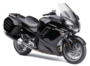
Kawasaki 1400 GTR (Concours 14)
Ниже представлены прямые ссылки на скачку сервисной документации.
Для Kawasaki 1400 GTR
- Руководство пользователя (Owners Manual) на Kawasaki 1400 GTR
- Сервисный мануал (Service Manual) на Kawasaki 1400 GTR
Обзор модели
- Kawasaki 1400 GTR
Категории:
- Сервисная документация
- Kawasaki документация
(Ocr-Read Summary of Contents of some pages of the Kawasaki 1400GTR ABS — 2011 Document (Main Content), UPD: 19 May 2023)
-
753, APPENDIX 17-31 Cable, Wire, and Hose Routing 1. Inlet Air Temperature Sensor Lead 2. Run the inlet air temperature sensor lead through the upper hole of the cover. 3. ABS Hydraulic Unit Lead (ABS models only) 4. Run the ABS hydraulic unit lead (ABS models only) through the lower hole of the cover. 5. Run the ABS hydraulic unit lead (ABS models only) under the fuel hose. 6. Run the ABS hydraulic unit lead (ABS model…
-
159, FUEL SYSTEM (DFI) 3-53 Inlet Air Pressure Sensor (Service Code 12) Output Voltage Inspection • Measure the output voltage at the ECU in the same way as input voltage inspection. Note the following. Digital M eter [A] Connector [B] Special Tool — Needle Adapter Set: 57001-1457 Inlet Air Pressure Senso r Outp ut Volt age Connections to ECU Meter (+) → Y/BL lead (terminal 38) Meter (–) → BR/BK le ad (termi n al 60) Output Voltage…
-
217, FUEL SYSTEM (DFI) 3-111 Fuel Line Fuel Pressure Inspection NOTE ○ Be sure the battery is fully charged. • Remove the fuel tank bolts [A] (see Fuel Tank Removal). ○ Do not disconnect the fuel pump and fuel level sensor lead connector. • Remove the fuel hose (see Fuel Hose Replacement in the Periodic Maintenance chapter). WARNING Be prepared for fuel spillage; any spilled fuel must be completely wiped up immediately. When the fuel hose is disconne…
-
240, 3-134 FUEL SYSTEM (DFI) Air Line Oil Draining A drain hose is connected to the bottom of the air cleaner part to drain water or oil accumulated in the cleaner part. • Visually check the catch tank [A] of the drain hose, if the water or oil accumulates in the tank. If any water or oil accumulates in the tank, remove the plug [B] from t he tank and drain it. WARNING Be sure reinstall the plug in the tank after draining. Oil on tires will make them slippery and can cau…
-
506, 12-44 BRAKES Anti-Lock Brake System (Equipped Models) How to Read Service Codes ○ Service codes are shown by a series of long and short blinks of the ABS indicator light (LED) as shown below. ○ Read 10th digit and unit digit as the ABS indicator light (LED) blinks. ○ When there are a number of faults, a maximum of all service codes (14 codes) can be stored and the display will begin starting from the small number code entered. ○ For the display pat…
-
316, 6-12 CLUTCH Clutch Cover Clutch Cover Removal • Remove: Engine Oil (Drain, see Engine Oil Change in the Periodic Maintenance chapter) Right Lower Fairing (see Lower Fairing Removal in the Frame c hapter) Clutch Cover Bolts [A ] Clutch Cover [B] Clutch Cover Installation • Apply silicone sealant to the area [A] where the mating surface of the crankcase touches the clutch cover gasket. Sealant — K…
-
463, BRAKES 12-1 12 Brakes Table of Contents Exploded View ……………………………………………………………………………………………………….. 12-3 Specifications ………………………………………………………………………………………………………… 12-12 Special Tools ………………………………………………………………………………………………………….. 12-13 Brake…
-
712, 16-100 ELECTRICAL SYSTEM Switches and Sensors Brake Light Timing Inspection • Refer to the Brake Light Switch Operation Inspection in the Periodic Maintenance chapter. Brake Light Timing Adjustment • Refer to the Brake Light Switch Operation Inspection in the Periodic Maintenance chapter. Switch Inspection • Using a hand tester, check to see that only the con- nections shown in the table have continuity (about zero ohms). ○ For the switch housings and the steering lock unit, refer to t…
-
16, 1-6 GENERAL INFORMATION Before Servicing Lubrication It is important to lubricate rotating or sliding parts during assembly to minimize wear during initial operation. Lubri- cation points are called out throughout this manual, apply the specific oil or grease as specified. Direction of Engine Rotation When rotating the c rankshaft by hand, the free play amount of rotating direction will affect the adjustment. Ro- tate the crankshaft to positive direction (clockwise vi…
-
607, FRAME 15-39 Pads 1. Fuel Tank 2. Align the pad with plate of the fuel tank. 3. Align the pad with weld of the fuel tank. 4. Pad 5. Pad 6. Pad 7. Pad 8. Pad 9. Guard
… -
48, 2-10 PERIODIC MAINTENANCE Torque and Locking Agent Torque Fastener N·m kgf·m ft·lb Remarks Oil Nozzles 2.9 0.30 26 in·lb Pinion Gear Assembly Nut 130 13.3 95.9 Speed Sensor Bolt 9.8 1.0 87 in·lb L Brakes Bleed Valves 7.8 0.80 69 in·lb Brake Caliper Holder Plate Bolt 64 6.5 47 Brake Hose Banjo Bolts 25 2.5 18 Brake Lever Pivot Bolt 1.0 0.10 9in·lb Si Brake Lever Pivot Bolt Locknut 5.9 0.60 52 in·lb Brake Pedal Bolt 8.8 0.90 78 in·lb Brake Pipe Joint Nuts 18 1.8 13 Brake Reservoir Bolt 7.…
-
590, 15-22 FRAME Fenders Front Fender Removal • Remove: Brake Hose Clamps [A] (Both Sides) Bolts [B] with Washer (Both Sides) Bolts [C] (Both Sides) Bracket [D] (Except the ZG1400B European Models) • Remove the front fender assy [E]. • Remove the screws [A]. • Separate the front fender covers [B] and front fender [C]. Front Fender Installation • Install the front fender covers to the front fender. ○ Insert the hooks [A] of the front fender cover i…
-
451, Kawasaki 1400GTR ABS — 2011 FINAL DRIVE 11-27 Front Bevel Gears ○ Stake [A] the nut [B] to secure it in place. CAUTION When staking the nut, be careful not to apply shock to the shaft and its bearing. Such a shock could damage the shaft and/or bearing. • Install the shim [A]. • Install the driven gear assy so that the pry ribs [B] up and down side. • Tighten the driven gear assy mounting bolts [D] to the specified torque. Torque — Driven Ge…
-
713, Kawasaki 1400GTR ABS — 2011 ELECTRICAL SYSTEM 16-101 Switches and Sensors Water Temperature Sensor Inspection • Remove the water temperature sensor (see Removal/In- stallation in the Water Temperature Sensor (Service Code 14) section in the Fuel System (DFI) chapter). • Suspend the sensor [A] in a container of coolant so that the threaded portion is submerged. • Suspend an accurate thermometer [B] with temperature sensing portions [C] located in almost the same depth. NOTE ○ The senso…
-
545, Kawasaki 1400GTR ABS — 2011 SUSPENSION 13-21 Swingarm Swingarm Removal • Use the center stand to support the motorcycle uptight. • Remove: Rear Wheel (see Rear Wheel Removal in the Wheels/Tires chapter) Propeller Shaft (see Propeller Shaft Removal in the Final Drive chapter) Muffler Body (see Muffler Body Removal in the Engine Tope End chapter) Bolts [A] Clamps [B] Bolts and Nuts [C] Axle Bracket [D] • Remove: Upper Tie-Rod Nut and Bolt [A] Lower Rear Shock Absorber Nut and Bolt [B] …
-
582, 15-14 FRAME Fairings • Remove: Rubber Damper [A] Bolts [B] Windshield [C] Windshield Installation • Put the rabber damper [A] onto the shape area of the damper [B]. • Tighten: Upper Fairing Removal • Remove: Inner Cover (see Inner Cover Removal) Windshield Screws [A] Electric Windshield Actuator Cover [B] • Remove: Middle Fairings (see Middle Fairing Removal) Rear View Mirror (see Rear View Mirror Removal) • …
-
602, 15-34 FRAME Saddlebag • Unscrew the screws [A] of the saddlebag lock assy. • Remove the saddlebag lock assy. • Unscrew the hinge nuts [A] and separate the lid [B] and case [C]. • Unscrew: Screws [D] • Remove: Hooks [E] Lid Cover [F] • Drill the surface of the rivet using a 1.0 to 1.5 mm drill bit NOTE ○ Stop drilling when the rivet head starts to turn with drill bit. • Remove the bands. Saddlebag assembly • Apply a non-permanent lockin…
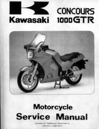
Руководство на английском языке по техническому обслуживанию и ремонту мотоциклов Kawasaki 1000GTR Concours.
- Издательство: Kawasaki Heavy Industries, Ltd.
- Год издания: 1999
- Страниц: —
- Формат: PDF
- Размер: 139,5 Mb

Руководство на английском языке по техническому обслуживанию и ремонту мотоциклов Kawasaki 1400GTR Concours 14.
- Издательство: Kawasaki Heavy Industries, Ltd.
- Год издания: 2007
- Страниц: 807
- Формат: PDF
- Размер: 17,2 Mb
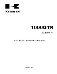
Руководство по эксплуатации и техническому обслуживанию мотоциклов Kawasaki 1000GTR (ZG1000-A1).
- Издательство: Kawasaki Heavy Industries, Ltd.
- Год издания: 2001
- Страниц: 35
- Формат: DOC
- Размер: 2,6 Mb

- About
- Blog
- Projects
- Help
-
Donate
Donate icon
An illustration of a heart shape - Contact
- Jobs
- Volunteer
- People
Bookreader Item Preview
texts
Kawasaki 1400GTR Service Manual
- Addeddate
- 2021-04-04 03:31:02
- Identifier
- manualzilla-id-6038149
- Identifier-ark
- ark:/13960/t1ck92x34
- Ocr
- tesseract 5.0.0-alpha-20201231-10-g1236
- Ocr_autonomous
- true
- Ocr_detected_lang
- en
- Ocr_detected_lang_conf
- 1.0000
- Ocr_detected_script
- Latin
- Ocr_detected_script_conf
- 0.9922
- Ocr_module_version
- 0.0.13
- Ocr_parameters
- -l ltz+fra+eng+Latin
- Ppi
- 300
comment
Reviews
There are no reviews yet. Be the first one to
write a review.
39
Views
DOWNLOAD OPTIONS
Uploaded by
chris85
on
SIMILAR ITEMS (based on metadata)