CA11E
User’s
HANDY CAL
Manual
(Voltage/Current Calibrator)
Thank you for purchasing the CA11E HANDY CAL. Prior to using, read this User’s Manual carefully to
fully and properly utilize all of the features of this instrument. Also, refer as needed to IM CA11E-02-E,
an additional User’s Manual for this instrument.
1. Safety Precautions
When operating the instrument, strictly observe the precautions below to ensure its correct and safe
operation. If used other than as instructed in this manual, Yokogawa Meters & Instruments Corporation
is not liable for any damage that may result.
The following safety symbols are used on the instrument and in the manual:
Danger! Handle with care.
This symbol indicates that the operator must refer to an explanation in the User’s Manual in
order to avoid risk of injury or death of personnel or damage to the instrument.
WARNING
Indicates a hazard that may result in the loss of life or serious injury of the user unless the
described instruction is abided by.
CAUTION
Indicates a hazard that may result in an injury to the user and/or physical damage to the
product or other equipment unless the described instruction is abided by.
NOTE
Indicates information that is essential for handling the instrument or, should be
noted in order to familiarize yourself with the instrument’s operating procedures and/or functions.
Damage to the instrument, personal injury or even death may result from electrical shock or
other factors. To avoid this, follow the precautions below:
Use where gases may be present
Do not operate the instrument in a location where flammable or explosive gas/vapor present. It is
extremely hazardous to operate the instrument in such an atmosphere.
External connection
If necessary to touch a circuit to make an external connection, turn off the power to that circuit,
ensure there is no voltage, then perform the connection. When replacing the batteries, disconnect the
lead cables in advance.
Disassembly
Do not disassemble or remodel the instrument yourself. This needs to be done by our service
personnel.
2. Names and Functions of Parts
Front View
<9> AC Adapter
connection jack
<1> Display unit
<3> POWER key
<2> Output value
setting keys
<4> OUTPUT
ON/OFF key
<5> Range selection
rotary switch
<6> MEASURE
(measurement)/
SOURCE
(generation)
selection switch
<7> Voltage input
<8> Voltage output/
terminals
current input and
output terminals
<1> Display unit
a. MEASURE
Lights up when MEASURE (measurement) is
selected using the selection switch <6>.
b. SOURCE
Lights up when SOURCE (generation) is selected
using the selection switch <6>.
c. CAL
Lights up in the calibration mode.
d. 0/FS
Lights up or blinks when offset or full-scale adjustment is performed in the calibration mode.
e.
—
+
This mark indicates the battery’s status. When lit, it indicates the batteries will soon need
replacing. When blinking, it indicates that they must be replaced (see Section 3, «Replacing the
Batteries»).
f. Main Seven Segment
Displays a measured value or an output value.
g. Sub Seven Segment
«SP» appears here when the sweep function (see Section 7, «Other Features») is selected in
SOURCE mode (signal generation). It also displays the lower two digits of a measured or an
output value in the calibration mode.
h. Displays the unit of the range selected.
i. OFF
In SOURCE mode (signal generation), it lights up when the output is turned off or when the
protective circuit is activated.
In MEASURE mode (measurement), it lights up only when the protective circuit is activated.
j. ON
It lights up when the output is turned on in SOURCE mode (signal generation).
<2> Output value setting keys
Sets an output value SOURCE mode (signal generation). The [ ]/[ ] keys are provided under the
lower four digits, whose values are increased or decreased in increments of 1. Carry of the digit is
applied to increasing the value (pressing the [ ] key) when it is 9. Borrow of the digit is applied to
decreasing the value (pressing the [ ] key) when it is 0.
For the 4-20 mA and 1-5 V ranges, see Subsection 5.2, «Generating DC current or DC voltage.»
<3> POWER key
Turns on/off the power supply. For more information, see Section 4, «Turning the Power On/Off.
<4> OUTPUT ON/OFF key
Turns the output on/off in SOURCE mode (signal generation). In MEASURE mode (measurement),
it returns measurement operation to normal status after the protective circuit is activated.
<5> Range selection rotary switch
Selects a range for SOURCE mode (signal generation) or MEASURE mode (measurement). Note
that the 4-20 mA and 1-5 V ranges are step output ranges in signal generation and are the same
as the 20 mA and 10 V ranges in measurement, respectively. For invalid ranges, terminal-to-
terminal connection becomes open, causing «-nC-» and «OFF» to appear on the display unit.
IM CA11E-01E
2nd Edition Aug. 2009 (KP)
WARNING
Rear View
Side View
(with the rear cover removed)
ON
<10> DIP switches
1 2 3 4
<11> Battery holder
Red
<12> Lead cables
Black
j
e
i
h
a
+ —
MEASURE
b
FS
SOURCE ON OFF
CAL
0
f
c
d
Yokogawa Meters & Instruments Corporation
-1-
International Sales Dept.
Tachihi Bld. No.2, 6-1-3, Sakaecho, Tachikawa-shi,Tokyo 190-8586 Japan
Phone: 81-42-534-1413, Facsimile: 81-42-534-1426
YOKOGAWA CORPORATION OF AMERICA (U.S.A.)
Phone: 1-800-888-6400 Facsimile: 1-770-254-0928
YOKOGAWA EUROPE B. V. (THE NETHERLANDS)
Euroweg 2, 3825 HD, Amersfoort, THE NETHERLANDS
Phone: 31-88-4641000 Facsimile: 31-88-4641111
YOKOGAWA AMERICA DO SUL LTDA. (BRAZIL)
Phone: 55-11-5681-2400 Facsimile: 55-11-5681-4434
YOKOGAWA ENGINEERING ASIA PTE. LTD. (SINGAPORE)
Phone: 65-6241-9933 Facsimile: 65-6241-2606
YOKOGAWA MEASURING INSTRUMENTS KOREA CORPORATION (KOREA)
Phone: 82-2-551-0660 to -0664 Facsimile: 82-2-551-0665
YOKOGAWA AUSTRALIA PTY. LTD. (AUSTRALIA)
Phone: 61-2-8870-1100 Facsimile: 61-2-8870-1111
YOKOGAWA INDIA LTD. (INDIA)
Phone: 91-80-4158-6000 Facsimile: 91-80-2852-1441
YOKOGAWA SHANGHAI TRADING CO., LTD. (CHINA)
Phone: 86-21-6239-6363 Facsimile: 86-21-6880-4987
YOKOGAWA MIDDLE EAST B. S. C (C) (BAHRAIN)
Phone: 973-17-358100 Facsimile: 973-17-336100
YOKOGAWA ELECTRIC CIS LTD. (RUSSIAN FEDERATION)
Phone: 7-495-737-7868 Facsimile: 7-495-737-7869
Notice regarding the Manual
<1> The information contained in this User’s Manual is subject to change without notice.
<2> Every effort has been made to ensure that the information contained herein is accurate.
However, should any concerns, errors, or omissions come to your attention, or if you have any
comments, please contact us.
<6> MEASURE (measurement) / SOURCE (generation) selection switch
Selects MEASURE (measurement) or SOURCE (generation).
<7> Voltage input terminals
Used to measure a voltage range.
<8> Voltage output/current input and output terminals
Used for SOURCE mode (signal generation) in the voltage range, and for MEASURE mode
(measurement) and SOURCE mode (signal generation) in the current range.
<9> AC Adapter connection jack
Used to connect an AC adapter (optional).
<10> DIP switches
See Section 7, «Other Features.»
<11> Battery holder
Contains four AA-size batteries. See Section 3, «Replacing the Batteries.»
<12> Lead cables for measurement or generation
Used to connect the instrument to the device under measurement/generation.
3. Replacing Batteries
When the
mark is blinking on the display unit, the batteries are exhausted. Replace them
+
—
according to the following procedure:
<1> Check that the power is turned off (disconnect the lead cables).
<2> Slide off the cover at the back of the instrument.
<3> Replace all four batteries with new ones. Insert them according to the polarity directions
shown inside the holder.
<4> After replacing the batteries, return the cover to the original position.
Connecting the AC Power (optional)
Before connecting the AC power
Strictly observe the following warnings to avoid electrical shock or damage to the instrument.
Do not use any AC adapter other than the dedicated AC adapter from Yokogawa.
Before connecting the power cord, check that the supply voltage matches the rated
voltage of the instrument.
Before connecting the power cord, check that the instrument’s power key is OFF.
Connection procedure:
<1> Check that the [POWER] key of the instrument is off.
<2> Connect the AC adapter (optional) to the instrument’s AC adapter connection jack. (Note that
unless the AC adapter is connected to the power outlet, the power cannot be turned on).
4. Turning the Power On/Off
Operating the POWER Key
When the instrument’s power is off, pressing and holding the [POWER] key for more than 1 second
causes the power to be turned on. Pressing the key again causes it to be turned off.
g
When the power is turned on, the instrument starts a self-test and displays «CA11E.» Then the
features selected using the range selection rotary switch and the MEASURE/SOURCE selection
switch start functioning.
• For battery-driven operations, disconnect the AC adapter from the instrument.
Automatic Power Off
In the factory setting, all indications start blinking if the instrument has not been operated for about
9.5 minutes. Then, if the instrument is not operated for another 30 seconds, it automatically turns
off. To disable this automatic power off feature, see Section 7, «Other Features.»
If you wish to keep the instrument turned on after the indications start blinking, press the [POWER]
key (or any other key). This causes the blinking to return to normal lighting, without changing the
previous settings.
5. SOURCE (generation)
5.1 Connecting the Output Terminals
<1> Insert the plugs of the supplied lead cables into the output terminals of the instrument.
<2> Connect the clips on the other ends of the cables to the input terminals of the device under
generation.
OUTPUT V/mA
Hi
Lo
Hi
—
+
Do not apply any voltages to the output terminals except for the 20 mA SINK range. If
voltage is applied mistakenly, the internal circuit may be damaged.
As the instrument is calibrated without the voltage drop of the lead cables, error due to
the resistance of the lead cables (approx. 0.1 Ω for go and return) must be considered for
load current measurement.
5.2 Generating DC Current or DC Voltage
The instrument generates voltage or current at a specified value through the output terminals. In valid
ranges, terminal-to-terminal connection opens, and the display unit indicates «-nC-» and «OFF.»
IM3E-2009.2
WARNING
CAUTION
IM CA11E-01E <1>
User’s
CA11E
HANDY CAL
Manual
In addition to this User’s Manual, there is another manual for the instrument,
IM CA11E-01-E, which provides instructions for its safe use and explains its
functions. Refer to it as needed.
8. Calibration Procedure
■ Calibration Procedure
To maintain a high level of accuracy, it is recommended that the CA11E HANDY CAL be calibrated
annually. The “Selecting the Standards” section below presents calibration methods using the
recommended standards.
■ Selecting the Standards
Source feature
Items to be
calibrated
DCV
20 mA Digital multimeter 20 mA(4-20 mA) Max.24 mA
20 mASINK
Measurement feature
Items to be
calibrated
DCV
Names of
standards
Digital multimeter
Digital multimeter,
standard DC
voltage generator
Names of
standards
Standard DC
voltage generator
(Voltage/Current Calibrator)
Range
100 mV
1000 mV
10 V
30 V
20 mASINK
Range
100 mV
1000 mV
10 V(1-5 V)
30 V
Measuring
range
Max.110 mV
Max.1.1 V
Max.11 V
Max.33 V
0.01 to 24 mA
5 to 28 V
Generated
value
100 mV
1 V
10 V
30 V
Accuracy Remarks
⫾(0.005%+5 µV)
⫾(0.005%+20 µV)
⫾(0.005%+200 µV)
⫾(0.005%+2 mV)
⫾(0.001%+0.8 µV)
Accuracy Remarks
⫾(0.01%/100 mV)
⫾(0.01%/1 V)
⫾(0.01%/10 V)
⫾(0.02%/30 V)
IM CA11E-02E
1st Edition Apr. 2006 (KP)
Model 7561
(Yokogawa)
or equivalent
Model 2552
(Yokogawa)
or equivalent
-2-
Yokogawa Meters & Instruments Corporation
International Sales Dept.
Tachihi Bld. No.2, 6-1-3, Sakaecho, Tachikawa-shi,Tokyo 190-8586 Japan
Phone: 81-42-534-1413, Facsimile: 81-42-534-1426
YOKOGAWA CORPORATION OF AMERICA (U.S.A.)
Phone: 1-770-253-7000 Facsimile: 1-770-251-2088
YOKOGAWA EUROPE B. V. (THE NETHERLANDS)
Phone: 31-334-64-1611 Facsimile: 31-334-64-1610
YOKOGAWA ENGINEERING ASIA PTE. LTD. (SINGAPORE)
Phone: 65-6241-9933 Facsimile: 65-6241-2606
YOKOGAWA AMERICA DO SUL S. A. (BRAZIL)
Phone: 55-11-5681-2400 Facsimile: 55-11-5681-1274
YOKOGAWA MEASURING INSTRUMENTS KOREA CORPORATION (KOREA)
Phone: 82-2-551-0660 to -0664 Facsimile: 82-2-551-0665
YOKOGAWA AUSTRALIA PTY. LTD. (AUSTRALIA)
Phone: 61-2-9805-0699 Facsimile: 61-2-9888-1844
YOKOGAWA INDIA LTD. (INDIA)
Phone: 91-80-4158-6000 Facsimile: 91-80-2852-1441
YOKOGAWA SHANGHAI TRADING CO., LTD. (CHINA)
Phone: 86-21-6880-8107 Facsimile: 86-21-6880-4987
YOKOGAWA MIDDLE EAST E. C. (BAHRAIN)
Phone: 973-358100 Facsimile: 973-336100
LTD. YOKOGAWA ELECTRIC (RUSSIAN FEDERATION)
Phone: 7-095-737-7868 Facsimile: 7-095-737-7869
IM3E-2006.2
■ Notice regarding the Manual
<1> The information contained in this User’s Manual is subject to change without notice.
<2> Every effort has been made to ensure that the information contained herein is accurate.
However, should any concerns, errors, or omissions come to your attention, or if you
have any comments, please contact us.
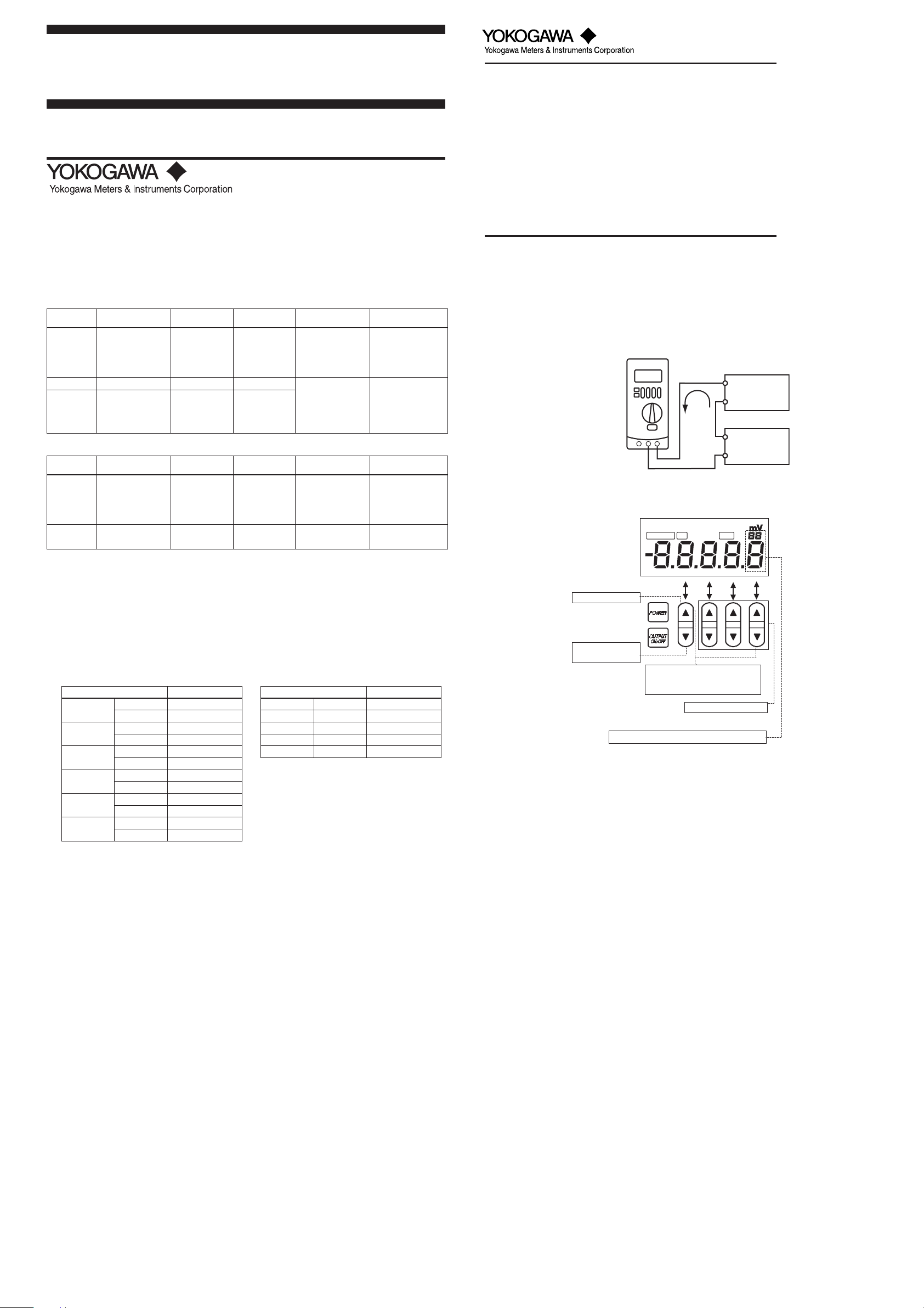
■ Calibration Precautions
• Connection for 20 mA SINK calibration
Connect the CA11E calibrator to the standard as shown below:
CA11E
H
DMM
current range
L
SINK
Lo
Hi
+
Constant-voltage
power supply
(Vo: 5-28V)
—
■ Assignment of Keys for Calibration
When the CA11E calibrator is in the calibration mode, keys are assigned as specified here.
20 mA
Standard DC
current generator
20 mA(4-20 mA) 20 mA ⫾0.02%/20 mA
■ Environmental Conditions for Calibration
Ambient temperature: 23 ⫾ 1°C
Relative humidity: 45 to 75% R.H
Warm-up: Warm-up time as specified for the standard
■ Calibration Points
• The calibration points are as specified in the following tables.
• It is possible to independently select the necessary range to be recalibrated.
• Always calibrate the zero (0) point and full scale (FS) as a pair for generation.
Source: Measurement:
Calibration points Standard Value
100 mV
1 V
10 V
30 V
20 mA
20 mA
SINK
*1: Make adjustments to CA11E according to the
reading of the standard (CA11E output Value)
as specified in the table.
00 mV
FS 100 mV
00 m V
FS 1000 mV
00 V
FS 10 V
00 V
FS 30 V
00 V
FS 20 mA
0.1 0.1 mA
FS 20 mA
Standard Value
*1
Calibration points
100 mV FS 100 mV
1 V FS 1 V
10 V FS 10 V
30 V FS 30 V
20 mA FS 20 mA
*2: Set the Value to the standard as specified in
the table.
■ Calibrating the Generation Feature
Operation procedure:
<1> Warm up the standard.
<2> Before turning on the power of the CA11E calibrator, connect it to the standard.
<3> Turn on the power of the instrument.
<4> Simultaneously press and hold the [▲1] and [▼4] keys (shown in the figure in the “Assign-
ment of Keys for Calibration” section below) for about 2 seconds to enter the calibration
mode.
<5> Select the generation range to calibrate using the MEASURE/SOURCE selection switch
and range selection rotary switch. The display unit shows “CAL,” “SOURCE,” “ON,” “0,” and
the lower limit.
<6> Read the output value of the CA11E using the standard (digital multimeter), and using the
[▲] and [▼] adjustment keys adjust the CA11E so that the output value is set to the offset
value. Then press the [▼1] input determination (ENTER) key to fix the setting.
After fixing the setting, the display unit reading changes to “CAL,” “SOURCE,” “ON,” “FS,”
and a full scale of the range.
<7> Read the output value of the CA11E using the standard (digital multimeter), and using the
[▲] and [▼] adjustment keys adjust the CA11E so that the output value is set to the full
scale value. Then press and hold the [▼1] input determination (ENTER) key for about 1
second to fix the setting.
After fixing the setting, the display unit shows “0 FS” blinking. Re-press and hold the [▼1]
input determination (ENTER) key for about 1 second to write the calibration coefficients to
the EEPROM of the instrument. (This overwrites the previous calibration coefficients.)
When this is complete, the instrument returns to the status in Step 5.
<8> Repeat Steps 5 to 7 for each range to be calibrated.
SOURCE
ON
Input cancellation key
Input determination
(ENTER) key
Mode switching (calibration or normal)
(Press and hold two keys
*2
Digit to be adjusted by the [▲4/▼4] adjustment keys
simultaneously for 2 seconds.)
Adjustment keys (six keys)
CAL
0
1234
■ Calibrating the Measurement Feature
Operation procedure:
<1> Warm up the standard.
<2> Before turning on the power of the CA11E calibrator, connect it to the standard.
<3> Turn on the power of the instrument.
<4> Simultaneously press and hold the [▲1] and [▼4] keys (shown in the figure in the “Assign-
ment of Keys for Calibration” section below) for about 2 seconds to enter the calibration
mode.
<5> Select the measurement range to calibrate using the MEASURE/SOURCE selection switch
and range selection rotary switch.
«CAL” and “MEASURE” appear and “FS” blinks on the display unit.
(If a value nearly equivalent to full scale has been input, a measured value and “FS”
appear.)
<6> Set up the standard in order to input the full scale value to the instrument. Wait until the
reading stabilizes, then press and hold the [▼1] input determination (ENTER) key for about
1 second to fix the setting.
<7> After fixing the setting, “0” and “FS” indications on the display unit start blinking. Re-press
and hold the [▼1] input determination (ENTER) key for about 1 second to write the calibration coefficients to the EEPROM of the instrument. (This overwrites the previous calibration
coefficients.)
<8> Repeat Steps 5 to 7 for each range to be calibrated.
To return to the previous step:
<9> To return to the previous step without fixing the setting, press the [▲1] input cancellation
key. Note that this is possible only before writing to the EEPROM.
To return to the normal operation mode:
<10>Simultaneously press and hold the [▲1] and [▼4] keys (shown in the figure in the “Assign-
ment of Keys for Calibration” section below) for about 2 seconds, or press the [POWER] key
to turn off the power once and then press it again to turn it back on.
IM CA11E-02E <1>
Назначение
Калибраторы электрических сигналов СА11Е, СА12Е, СА51, СА71, СА150, СА450 (далее — калибраторы) предназначены для измерения и воспроизведения напряжения постоянного и переменного тока, силы постоянного тока, частоты переменного тока, электрического сопротивления постоянному току (в том числе от термопар и термопреобразователей сопротивления).
Описание
Калибраторы представляют собой портативные электрические приборы с расположенными на передней панели жидкокристаллическим дисплеем с регулируемой подсветкой и клавишами, которые группируются в соответствии с их функциями.
Калибраторы различных моделей отличаются функциональными возможностями, метрологическими и техническими характеристиками. Функциональные возможности калибраторов в зависимости от модели приведены в таблице 1.
Питание калибраторов осуществляется как от батарей, так и от сети переменного тока при использовании специального адаптера. Наличие во всех калибраторах, кроме СА12Е, встроенного источника питания постоянного тока 24 В позволяет использовать калибраторы в качестве источника питания для датчиков.
На рисунке 1 приведён общий вид калибраторов CA11E, CA12E, на рисунке 2 приведена схема пломбирования калибраторов CA11E, CA12E.
Вид сзади (со снятой задней крышкой)
Место нанесения поверительной наклейки
Таблица 1
|
Функция |
СА11Е |
СА12Е |
СА51 |
СА71 |
СА150 |
СА450 |
|
Измерение напряжения постоянного тока |
+ |
+ |
+ |
+ |
+ |
+ |
|
Измерение силы постоянного тока |
+ |
— |
+ |
+ |
+ |
+ |
|
Измерение сопротивления постоянному току |
— |
+ |
+ |
+ |
+ |
+ |
|
Измерение напряжения переменного тока |
— |
— |
+ |
+ |
— |
+ |
|
Измерение частоты |
— |
— |
+ |
+ |
+ |
+ |
|
Воспроизведение напряжения постоянного тока |
+ |
+ |
+ |
+ |
+ |
— |
|
Воспроизведение силы постоянного тока |
+ |
— |
+ |
+ |
+ |
+ |
|
Воспроизведение сопротивления постоянному току |
— |
+ |
+ |
+ |
+ |
— |
|
Воспроизведение частоты |
— |
— |
+ |
+ |
+ |
— |
|
Измерение сигналов термопар |
— |
+ |
— |
+ |
+ |
— |
|
Воспроизведение сигналов термопар |
— |
+ |
+ |
+ |
+ |
— |
|
Измерение сигналов термометров сопротивления |
— |
+ |
— |
+ |
+ |
— |
|
Воспроизведение сигналов термометров сопротивления |
— |
+ |
+ |
+ |
+ |
— |
Калибраторы CA51, CA71, CA150, CA450 состоят из двух рабочих секций (измерение и воспроизведение), работающих независимо друг от друга и гальванически развязанных. Это позволяет использовать калибраторы для одновременного воспроизведения выходного сигнала и измерения входного сигнала. На рисунке 3 приведён общий вид калибраторов CA51, CA71, CA150, 4 — общий вид калибратора CA450, на рисунке 5 -схема пломбирования калибраторов CA51, CA71, CA150, CA450.
Т аблица 2
|
Кали братор |
Наименова ние программ ного обеспечения |
Идентифи кационное наименова ние программ ного обеспечения |
Номер версии (идентификационный номер) программного обеспечения |
Цифровой идентификатор программного обеспечения |
Алгоритм вычисления цифрового идентифи катора |
|
СА11Е, СА12Е |
БПО |
Не используется |
Не ниже 1.00 |
Зависит от версии |
MD5 |
|
СА51, СА71 |
Не ниже 1.17 |
||||
|
СА150 |
Не ниже 1.02 |
||||
|
СА450 |
Не ниже 1.00 |
Программное обеспечение
Для преобразования измеренных аналоговых сигналов в цифровой код и преобразование цифрового кода в аналоговую форму используются алгоритмы, реализованные в базовом программном обеспечении (БПО) и записанные в постоянной памяти калибраторов. Базовое программное обеспечение (БПО) устанавливается в энергонезависимую память на заводе изготовителе во время производственного цикла. Оно недоступно пользователю и не подлежит изменению на протяжении всего времени функционирования изделия, что соответствует уровню защиты «А» в соответствии с МИ 3286-2010.
Метрологические характеристики калибраторов нормированы с учетов влияния на них БПО.
Идентификационные данные метрологически значимого ПО приведены в таблице 2.
Технические характеристики
Основные метрологические и технические характеристики калибраторов указаны в таблицах 3-10, технические — в таблице 11.
В таблицах 3-10:
1) Х — измеренное или установленное значение /100%;
2) Допускаемый температурный коэффициент составляет ± (0,2 До)/ °С для СА51, СА71 и ± (0,1 До)/ °С для остальных моделей, кроме режимов, указанных в примечании к таблице 3;
3) Во всех таблицах допуск на основную погрешность для каждого типа термопары указан без учёта погрешности канала компенсации температуры холодного спая.
4) Характеристики канала компенсации температуры холодного спая термопары:
— диапазон измерений температуры — от минус 10 °С до плюс 50 °С;
— пределы допускаемой абсолютной погрешности канала компенсации температуры холодного спая составляют:
± 0,5 °С в диапазоне температуры от 18 °С до 28 °С (в диапазоне температур от
0 °С до 40 °С для ТХК (L));
± 1 °С в диапазоне от минус 10 до плюс 18 °С и в диапазоне от 28 до 50 °С.
Таблица 3 — Основные метрологические характеристики калибраторов СА11Е
|
Функция |
Диапазоны сигналов |
Разрешающая способность |
Пределы допускаемой основной погрешности, До |
|
|
Воспроизведение |
(0 • |
.. 30) В |
10 мВ |
± (0,05 % Х + 20 мВ) |
|
напряжения |
(0 • |
.. 11) В |
1 мВ |
± (0,05 % Х + 2 мВ) |
|
постоянного тока |
(1 |
.. 5) В |
шаг 1 В |
|
|
(0 . |
• 1,1) В |
0,1 мВ |
± (0,05 % Х + 0,2 мВ) |
|
|
(0 … |
110) мВ |
0,01 мВ |
± (0,05 % Х + 50 мкВ) |
|
|
Воспроизведение |
(0 .. |
24) мА |
1 мкА |
± (0,05 % Х + 4 мкА) |
|
силы постоянного |
(4 •• |
20) мА |
шаг 4 мА |
|
|
тока |
(0,1 . |
.. 24) мА |
1 мкА |
± (0,1 % Х + 4 мкА) |
|
Измерение |
(- 30 |
.. + 30) В |
10 мВ |
± (0,05 % Х + 20 мВ) |
|
напряжения |
(- 11 |
.. + 11) В |
1 мВ |
± (0,05 % Х + 2 мВ) |
|
постоянного тока |
(- 1,1 |
…+ 1,1) В |
0,1 мВ |
± (0,05 % Х + 0,2 мВ) |
|
(- 110 . |
. + 110) мВ |
0,01 мВ |
± (0,05 % Х + 0,07 мВ) |
|
|
Измерение силы постоянного тока |
(- 24 .. |
. + 24) мА |
1 мкА |
± (0,05 % Х + 4 мкА) |
Примечание к таблице 3: допускаемый температурный коэффициент для диапазона воспроизведения (0 …110) мВ и измерения (- 110 … + 110) мВ находится в пределах ± (0,005 % Х + 10 мкВ)/ °С.
|
Тип вход ного сигнала |
Диапазоны |
Разре шающая способ ность |
Пределы допускаемой основной погрешности |
|
|
в режиме воспроизведений |
в режиме измерений |
|||
|
ТХА (К) |
(- 200…+ 1372) °С |
0,1 °С |
± (0,05 % Х + 1,0 °С) при температуре > — 100 °С ± (0,05 % Х + 2,0 °С) при температуре < — 100 °С |
± (0,07 % Х + 1,5 °С) при температуре > — 100°С ± (0,07 % Х + 2,0 °С) при температуре <-100 °С |
|
ТХКн (E) |
(- 200…+ 1000) °С |
|||
|
ТЖК (J) |
(- 200…+ 1200) °С |
|||
|
ТМК (T) |
(- 200… + 400) °С |
|||
|
ТНН (N) |
(- 200…+ 1300) °С |
|||
|
ТПП (R), (S) |
С ° 0) О (0 |
1°С |
± (0,05 % Х + 3 °С) |
± (0,07 % Х + 3 °С) |
|
С ° 00 6 7 0 0 |
± (0,05 % Х + 2 °С) |
± (0,07 % Х + 2 °С) |
||
|
ТПР (В) |
(600 … 1000)°С |
1°С |
± (0,05 % Х + 4 °С) |
± (0,07 % Х + 4 °С) |
|
(1000 … 1800)°С |
± (0,05 % Х + 3 °С) |
± (0,07 % Х + 3 °С) |
||
|
L |
(- 200 … + 900) °С |
0,1 °С |
± (0,05 % Х + 0,5 °С) при температуре > 0 °С ± (0,05 % Х + 1,0 °С) при температуре < 0 °С |
± (0,07 % Х + 1,5 °С) при температуре > 0 °С ± (0,07 % Х + 2,0 °С) при температуре < 0 °С |
|
U |
(- 200… + 400) °С |
|||
|
100 мВ |
(- 10 … + 110) мВ |
10 мкВ |
± (0,05 % Х +30 мкВ) |
— |
|
(- 110 …+ 110) мВ |
— |
± (0,05 % Х +30 мкВ) |
||
|
Pt 100 |
(- 200 … + 850) °С |
0,1 °С |
± (0,05 % Х + 0,6 °С) |
± (0,05 % Х + 0,6 °С) |
|
400 Ом |
(0 … 400) Ом |
0,1 Ом |
± (0,05 % Х+ 0,2 Ом) |
± (0,05 % Х+ 0,2 Ом) |
Таблица 5 — Воспроизведение / измерение сигналов термопар (для СА51, CA71)
|
Разре |
Пределы допускаемой основной погрешности |
||||
|
Тип термопары |
Диапазоны, °С |
шающая способ ность, °С |
В режиме воспроизведения |
В режиме измерения (только для СА71) |
|
|
ТХА (К) |
— 200 |
.. 1372 |
0,1 |
± (0,02 % Х + 0,5 °С) |
± (0,05 % Х + 1,5 °С) при температуре |
|
ТХКн (Е) |
-200 |
.. 1000 |
0,1 |
при температуре > -100 °С |
|
|
ТЖК (J) |
-200 |
.. 1200 |
0,1 |
± (0,02 % Х + 1,0 °С) при температуре < -100 °С |
> -100 °С |
|
ТМК (Т) |
-200 |
… 400 |
0,1 |
± (0,02 % Х + 0,5 °С) |
± (0,05 % Х + 2,0 °С) |
|
ТНН (N) |
-200 |
.. 1300 |
0,1 |
при температуре > 0 °С |
при температуре |
|
L |
-200 |
… 900 |
0,1 |
± (0,02 % Х + 1,0 °С) |
< -1 0 О ° О |
|
U |
-200 |
… 400 |
0,1 |
при температуре < 0 °С |
|
|
ТПР(8), (R) |
0 .. |
1768 |
1 |
± (0,02 % Х +2,5 °С) при температуре < 100 °С ± (0,02 % Х + 1,5 °С) при температуре > 100 °С |
± (0,05 % Х + 2 °С) при температуре >100°С |
|
ТПП (B) |
600 |
. 1800 |
1 |
± (0,02 % Х + 2 °С) при температуре < 1000 °С ± (0,02 % Х + 1,5 °С) при температуре > 1000 °С |
± (0,05 % Х + 3 °С) при температуре <100°С |
|
Функция |
Диапазоны сигналов |
Разрешающая способность |
Пределы допускаемой основной погрешности |
|
Воспроизведение напряжения постоянного тока |
В м 0) 0 — |
10 мкВ |
± (0,02 % Х + 15 мкВ) |
|
(0.1,1) В |
0,1 мВ |
± (0,02 % Х + 0,1 мВ) |
|
|
(0.11) В |
1 мВ |
± (0,02 % Х + 1 мВ) |
|
|
(0.30) В |
10 мВ |
± (0,02 % Х + 10 мВ) |
|
|
Воспроизведение силы постоянного тока |
(0.24) мА |
1 мкА |
± (0,025 % Х + 3 мкА) |
|
(4.20) мА |
4 мА |
||
|
(0,1.24) мА |
1 мкА |
± (0,05 % Х + 3 мкА) |
|
|
Воспроизведение сопротивления постоянному току |
(0.400) Ом |
0,01 Ом |
± (0,025 % Х + 0,1 Ом) |
|
Воспроизведение частоты и импульсных циклов |
(1.500) Гц |
0,1 Гц |
± 0,2 Гц |
|
(90.1100) Гц |
1 Гц |
± 1 Гц |
|
|
(0,9 кГц.11) кГц |
0,1 кГц |
± 0,1 кГц |
|
|
(1.99999) циклов |
1 цикл |
— |
|
|
Измерение напряжения постоянного тока |
(0.± 110) мВ |
10 мкВ |
± (0,025 % Х + 20 мкВ) |
|
(0.± 1,1) В |
0,1 мВ |
± (0,025 % Х + 0,2 мВ) |
|
|
(0.± 11) В |
1 мВ |
± (0,025 % Х + 2 мВ) |
|
|
(0.± 110) В |
0,01 В |
± (0,05 % Х + 20 мВ) |
|
|
Измерение силы постоянного тока |
(0. ± 24) мА |
1 мкА |
± (0,025 % Х + 4 мкА) |
|
(0.± 100) мА |
10 мкА |
± (0,04 % Х + 30 мкА) |
|
|
Измерение сопротивления постоянному току (3-х проводное соединение) |
(0.400) Ом |
0,01 Ом |
± (0,05 % Х + 0,1 Ом) |
|
Измерение напряжения переменного тока в диапазоне частот от 45 Гц до 65 Гц |
(0.1,1) В |
1 мВ |
± (0,5 % Х + 5 мВ) |
|
(0.11) В |
0,01 В |
± (0,5 % Х + 0,05 В) |
|
|
В 0) (0 |
0,1 В |
± (0,5 % Х + 0,5 В) |
|
|
(0.300) В |
1 В |
± (0,5 % Х + 2 В) |
|
|
Измерение частоты, счет импульсов |
(1.100) Гц |
0,01 Гц |
± 0,02 Гц |
|
(1.1000) Гц |
0,1 Гц |
± 0,2 Гц |
|
|
ц Г к 01 ,0 (0, |
0,001 кГц |
± 0,002 кГц |
|
|
(0.99999) СРМ |
1 СРМ |
— |
|
|
(0.99999) СРН |
1 СРН |
— |
Примечания к таблице 6:
СРМ — количество импульсов в минуту, СРН — количество импульсов в час.
Таблица 7- Воспроизведение / измерение сигналов термометров сопротивления (СА51, СА71, СА150)_
|
Тип термометра сопротивления |
Диапазоны, °С |
Разрешающая способность, °С |
Пределы допускаемой основной погрешности |
|
|
В режиме воспроизведения |
В режиме измерения (кроме СА51) |
|||
|
Pt100 W=1,385 W=1,391 |
-200 … 850 |
0,1 |
± (0,025 % Х + 0,3 °С) |
± (0,05 % Х + 0,6 °С) |
|
-200 … 500 |
Примечание к таблице7: использовать трехпроводное соединение.
Таблица 8- Воспроизведение / измерение сигналов термопар (для СА150)
|
Тип термо пары |
Диапазоны, °С |
Разрешающая способность, °С |
Пределы допускаемой основной погрешности |
|
|
В режиме воспроизведения |
В режиме измерения |
|||
|
ТХА (К) |
— 2 О О — 0 о |
0,1 |
± (0,02 % Х + 0,8 °С) |
± (0,05 % Х + 1,5 °С) при температуре от минус 100 °С и выше ± (0,05 % Х + 2,0 °С) при температуре от минус 100 °С и ниже |
|
2 7 3 0 0 — |
± (0,02 % Х + 0,5 °С) |
|||
|
ТХКн (Е) |
0 0 — 0 0 2 — |
0,1 |
± (0,02 % Х + 0,6 °С) |
|
|
— 0 о 0 о о |
± (0,02 % Х + 0,4 °С) |
|||
|
ТЖК (J) |
0 0 — 0 0 2 — |
0,1 |
± (0,02 % Х + 0,7 °С) |
|
|
— 0 о 2 о о |
± (0,02 % Х + 0,4 °С) |
|||
|
ТМК (Т) |
0 0 — 0 0 2 — |
0,1 |
± (0,02 % Х + 0,8 °С) |
|
|
— 0 о 4 о о |
± (0,02 % Х + 0,5 °С) |
|||
|
ТНН (N) |
-200 … 0 |
0,1 |
± (0,02 % Х + 1,0 °С) |
|
|
0 3 О о |
± (0,02 % Х + 0,5 °С) |
|||
|
L |
-200 … 900 |
0,1 |
± (0,02 % Х + 0,5 °С) |
|
|
U |
-200 … 0 |
0,1 |
± (0,02 % Х + 0,7 °С) |
|
|
0 … 400 |
± (0,02 % Х + 0,5 °С) |
|||
|
ТПР (B) |
6 О О 0 о о |
1 |
± (0,02 % Х + 1,5 °С) |
± (0,05 % Х + 3 °С) |
|
0 2 8 0 0 0 |
± (0,02 % Х + 1,0 °С) |
± (0,05 % Х + 2 °С) |
||
|
ТПП (R), (S) |
0 0 о |
1 |
± (0,02 % Х + 2,0 °С) |
± (0,05 % Х + 3 °С) |
|
8 6 7 0 0 |
± (0,02 % Х + 1,2 °С) |
± (0,05 % Х + 2 °С) |
||
|
ТХК (L) для опции «/R» |
0 0 — 0 0 2 — |
0,1 |
± (0,02 % Х + 0,5 °С) |
± (0,02 % Х + 2,0 °С) |
|
— 0 о 8 о о |
± (0,02 % Х + 0,3 °С) |
± (0,02 % Х + 1,5 °С) |
|
Функция |
Услов ный диапазон |
Диапазон измерения / воспроизведения |
Разреша ющая способ ность |
Пределы допускаемой основной погрешности |
|
Воспроизведение напряжения постоянного тока |
100 мВ |
(0 . ± 110) мВ |
1 мкВ |
± (0,02 % Х + 10 мкВ) |
|
1 В |
(0 . ± 1,1) В |
10 мкВ |
± (0,02 % Х + 0,05 мВ) |
|
|
10 В |
(0 . ± 11) В |
0,1 мВ |
± (0,02 % Х + 0,5 мВ) |
|
|
30 В |
(0 . ± 30) В |
10 мВ |
± (0,02 % Х + 10 мВ) |
|
|
Воспроизведение силы постоянного тока |
20 мА |
(0 … +22) мА |
1 мкА |
± (0,025 % Х + 3 мкА) |
|
(0 … -22) мА |
1 мкА |
± (0,025% Х + 6 мкА) |
||
|
Воспроизведение сопротивления постоянному току |
500 Ом |
(0 … 550) Ом |
0,01 Ом |
± (0,02 % Х + 0,1 Ом) |
|
5 кОм |
(0 … 5,5) кОм |
0,1 Ом |
± (0,05 % Х + 1,5 Ом) |
|
|
50 кОм |
(0 … 55 кОм |
1 Ом |
± (0,1 % Х + 50 Ом) |
|
|
Воспроизведение импульсов |
100 Гц |
ц Г 0) |
0,01 Гц |
± 0,05 Гц |
|
1000 Гц |
(90.1100) Гц |
0,1 Гц |
± 0,5 Гц |
|
|
10 кГц |
(0,9.11) кГц |
0,1 кГц |
± 0,1 кГц |
|
|
50 кГц |
(9..50) кГц |
1 кГц |
± 1 кГц |
|
|
А СРМ |
С «в 1 2 = ) |
0,1 СРМ |
± 0,5 СРМ |
|
|
Измерение напряжения постоянного тока |
500 мВ |
(0 . ± 500) мВ |
10 мкВ |
± (0,02 % Х + 50 мкВ) |
|
5 В |
(0 . ± 5) В |
0,1 мВ |
± (0,02 % Х + 0,5 мВ) |
|
|
35 В |
(0 . ± 35) В |
1 мВ |
± (0,025 % Х + 5 мВ) |
|
|
Измерение силы постоянного тока |
20 мА |
(0 . ± 20) мА |
1 мкА |
± (0,025 % Х + 4 мкА) |
|
100 мА |
(0 . ± 100) мА |
10 мкА |
± (0,04 % Х + 30 мкА) |
|
|
Измерение сопротивления постоянному току |
500 Ом |
(0 . 500) Ом |
0,01 Ом |
± (0,055 % Х + 0,075 Ом) |
|
5 кОм |
(0 . 5) кОм |
0,1 Ом |
± (0,055 % Х + 0,75 Ом) |
|
|
50 кОм |
(0 … 50) кОм |
1 Ом |
± (0,055 % Х + 10 Ом) |
|
|
Измерение частоты |
100 Гц |
ц Г 0) |
0,01 Гц |
± 0,02 Гц |
|
1000 Гц |
(1 . 1100) Гц |
0,1 Гц |
± 0,2 Гц |
|
|
10 кГц |
(0,001 .11) кГц |
0,001 кГц |
± 0,002 кГц |
Примечание к таблице 9: * СРМ — количество импульсов в минуту;
|
Таблица 1 |
0 — Основные метрологические характеристики калибраторов СА450 |
||
|
Функция |
Диапазоны сигналов |
Разреша ющая способ ность |
Пределы допускаемой основной погрешности, До |
|
Измерение напряжения постоянного тока |
(-600 … 600) мВ |
0,1 мВ |
± (0,09 % Х+ 0,2 мВ) |
|
В 6) 6 — |
0,001 В |
± (0,09 % Х + 0,001 В) |
|
|
(- 60 … 60) В |
0,01 В |
± (0,09 % Х + 0,01 В) |
|
|
(- 600 … 600) В |
0,1 В |
± (0,09 % Х + 0,1 В) |
|
|
— 0 О О 0 о ) В |
1 В |
± (0,1 % Х + 1 В) |
|
|
Измерение напряжения переменного тока1) |
(0 … 600) мВ |
0,1 мВ |
± (0,5 % Х + 0,5 мВ), f = 50/60Гц; ± (1,0 % Х + 0,5 мВ), f = (40.500) Гц; ± (1,5 % Х + 0,5 мВ), f = (0,5.1) кГц |
|
В 6) (0 |
0,001 В |
± (0,5 % Х + 0,005 В), f = 50/60Гц; ± (1,0 % Х + 0,005 В), f = (40.500) Гц; ± (1,5 % Х + 0,005 В), f = (0,5.1) кГц |
|
|
(0 … 60) В |
0,01 В |
± (0,5 % Х + 0,05 В), f = 50/60Гц; ± (1,0 % Х + 0,05 В), f = (40.500) Гц; ± (1,5 % Х + 0,05 В), f = (0,5.1) кГц |
|
|
(0 … 600) В |
0,1 В |
± (0,5 % Х + 0,5 В), f = 50/60Гц; ± (1,0 % Х + 0,5 В), f = (40.500) Гц; ± (1,5 % Х + 0,5 В), f = (0,5.1) кГц |
|
|
0 0 О ) В |
1 В |
± (0,5 % Х + 5 В), f = 50/60Гц; ± (1,0 % Х + 5 В), f = (40.500) Гц |
|
|
Измерение силы постоянного тока |
(- 30 … 30) мА |
0,001 мА |
± (0,05 % Х + 0,002 мА) |
|
(- 100 … 100) мА2) |
0,01 мА |
± (0,05 % Х + 0,02 мА) |
|
|
Измерение сопротивления постоянному току |
(0 … 600) Ом |
0,1 Ом |
± (0,2 % Х + 0,2 Ом) |
|
(0 .6) кОм |
0,001 кОм |
± (0,2 % Х + 0,001 кОм) |
|
|
(0 .60) кОм |
0,01 кОм |
± (0,2 % Х + 0,01 кОм) |
|
|
(0 .600) кОм |
0,1 кОм |
± (0,2 % Х + 0,1 кОм) |
|
|
(0 .6) МОм |
0,001 МОм |
± (0,35 % Х + 0,003 МОм) |
|
|
(0 .60) МОм |
0,01 МОм |
± (1 % Х + 0,02 МОм) — для диапазона от 0 до 40 МОм; ± (2 % Х + 0,02 МОм) — для диапазона от 40 до 60 МОм |
|
|
Измерение частоты периодических сигналов |
(10 .199,99) Гц |
0,01 Гц |
± (0,005 % Х + 0,01 Гц) |
|
(90 .1999,9) Гц |
0,1 Гц |
± (0,005 % Х + 0,1 Гц) |
|
|
(0,9 .19,999) кГц |
0,001 кГц |
± (0,005 % Х + 0,001 кГц) |
|
|
Воспроизведение силы постоянного тока |
(0.20) мА |
0,001 мА |
± 0,05 % от диапазона |
Примечания к таблице 10:
1) Погрешности нормируются для значений напряжений, больших 0,05 от установленного предела измерения (до 600 В включительно), и больших 200 В для предела 1000 В.
Таблица 11 — Технические характеристики калибраторов
2) При использовании выхода LOOP POWER допускается только диапазон 30 мА.
|
Параметр |
СА11Е, СА12Е |
СА51, СА71 |
СА150 |
СА450 |
|
Максимальное число разрядов индикаторов |
5 |
4 |
5 |
|
|
Масса, кг, не более |
0,44 |
0,73 |
1,0 |
0,6 |
|
Габаритные размеры, мм, не более |
92х192х42 |
190х120х55 |
124х251х70 |
90х192х49 |
|
питан ие |
Постоянный ток |
6 В |
12 В или батарея |
6 В |
|
Переменн ый ток |
напряжение |
220 В ± 10 % |
||
|
частота |
50 Гц ± 2 % |
|||
|
Т емпература транспортирования и хранения, °С |
— 20 … + 50 |
— 20 … + 60 |
— 40 … + 70 |
|
|
Рабочие условия |
температура, °С |
0 … + 50 |
0. + 40 |
— 20 … + 55 |
|
влажность*, % |
(20 … 80) % (не более 70 % при температуре > 40 °С) |
|||
|
Нормальные условия |
температура, °С |
23 ± 5 |
||
|
влажность*, % |
5 7 5 4 |
Примечание к таблице 11: * — без конденсации влаги.
Знак утверждения типа
Знак утверждения типа наносится на титульный лист руководства по эксплуатации типографским способом.
Комплектность
В комплект поставки калибраторов входят:
Калибратор (по заказу) руководство по эксплуатации методика поверки датчик RJ (опционально) комплект ЗИП
дополнительные принадлежности (по заказу).
Поверка
осуществляется по документу МП 53468-13 «Калибраторы электрических сигналов СА11Е СА12Е, СА51, СА71, СА150, СА450. Методика поверки», утверждённому ГЦИ СИ ФГУП «ВНИИМС» 11.01.2013.
Перечень оборудования для поверки: калибратор универсальный Fluke 5520A (воспроизведение напряжения постоянного тока DU= = ± (0,000018 х U + 1,5 мВ), воспроизведение напряжения переменного тока Аи^ = ± (0,0008 х U + 6 мкВ), воспроизведение силы постоянного тока Ai= = ± (0,0001×1 + 25 мкА), воспроизведение сопротивления AR = ± (0,004 х 10-2 х R + 0,001 Ом), воспроизведение частоты периодических сигналов AF = ± (2,5 х 10-6 х F + 5 мкГц)) калибратор — вольтметр универсальный В1-28 (Au = ± (0,003 % U + 0,0003 % U); Ai = ± (0,006 % I + 0,002 % 1м)), компаратор напряжений Р3001М1 (кл.т. 0,0005), омметр цифровой Щ 306-1 (кл.т. 0,005/0,001), мера электрического сопротивления постоянного тока многозначная Р 3026-1 (кл.т. 0,002/1,5.10-6).
Сведения о методах измерений
Методы измерений приведены в Руководствах по эксплуатации на калибраторы электрических сигналов СА11Е, СА12Е, СА51, СА71, СА150, СА450.
Нормативные документы, устанавливающие требования к калибраторам электрических сигналов СА11Е, СА12Е, СА51, СА71, СА150, СА450:
ГОСТ 22261-94. ЕССП. Средства измерения электрических и магнитных величин. Общие технические условия.
ГОСТ 14014-91. Приборы и преобразователи измерительные цифровые напряжения, тока, сопротивления. Общие технические требования.
ГОСТ 8.028-86 Государственная система обеспечения единства измерений. Государственный первичный эталон и государственная поверочная схема для средств измерений электрического сопротивления.
ГОСТ 8.027-2001 Государственная система обеспечения единства измерений. Государственная поверочная схема для средств измерений постоянного электрического напряжения и электродвижущей силы.
Рекомендации к применению
— выполнение работ по оценке соответствия промышленной продукции и продукции других видов, а также иных объектов установленным законодательством Российской Федерации обязательным требованиям.
File Specifications:842/842276-ca11e.pdf file (19 Mar 2023) |
Accompanying Data:
YOKOGAWA CA11E Test Equipment PDF Operation & User’s Manual (Updated: Sunday 19th of March 2023 12:01:15 PM)
Rating: 4.8 (rated by 45 users)
Compatible devices: AQ7280 OTDR, DL7440, CA550, 2553A, DL 1540, AQ1210A, DL6000 Series, CA320.
Recommended Documentation:
Operation & User’s Manual (Text Version):
(Ocr-Read Summary of Contents of some pages of the YOKOGAWA CA11E Document (Main Content), UPD: 19 March 2023)
-
YOKOGAWA CA11E User Manual
-
YOKOGAWA CA11E User Guide
-
YOKOGAWA CA11E PDF Manual
-
YOKOGAWA CA11E Owner’s Manuals
Recommended: 122-466B000, MS-4, POEINJ1GI, Dolphin DX35
Links & Tools
-
Fuel Cell Technology ALCOSCAN AL4000 User’s Manual The Fuel cell sensor type, Alcoscan AL4000 is the coin operated breathalyzer. It is used in restaurants, to prevent alcohol related traffic accidents by customers. The instructions are displayed on LCD, the lamp will be lit to show warning depending …
AL4000 6
-
1. Safety PrecautionsThis product is designed to be used by a person with specialized knowledge.When operating the instrument, be sure to observe the cautionary notes given below to ensure correct and safe use of the instrument. If you use the instrument in any way other than as instructed in this manual, th …
MY10-01 2
-
Philips Medical SystemsConverter test kit OPTIMUSfor OPTIMUS 50/65/80 generatorsrelease 3.x with converters 4512 104 7231×4512 104 91681Level 1 DocumentationThis document and the information contained in it is strictly reserved for current Philips Medical Systems («Philips») personnel, Phil …
Optimus 53
-
PageAttentionInternational Electrical SymbolsFeaturesIntroductionEnvironmental ConditionsTechnical Specification1. Dc Voltage2. Ac Voltage3. Dc Current5. Resistance6. Capacitance4. AC Current7. Temperature8. Frequency9. Diode10 . Transistor hFE11. Open circuit test12. …
UT2000 series 20
Operating Impressions, Questions and Answers:
- Home
- Brands
- YOKOGAWA Manuals
- YOKOGAWA CA11E HANDY CAL
- YOKOGAWA CA11E HANDY CAL User Manual
Download or browse on-line these Operation & User’s Manual for YOKOGAWA CA11E HANDY CAL Test Equipment.
YOKOGAWA CA11E HANDY CAL Manual Information:
|
This manual for YOKOGAWA CA11E HANDY CAL, given in the PDF format, is available for free online viewing and download without logging on. |
Download Manual |
Summary of Contents:
|


User’s
Manual
How to Replace and Dispose the Batteries
This is an explanation about the new EU Battery Directive (DIRECTIVE 2006/66/EC).
This directive is valid in the EU only. Batteries are included in this product.
When you remove batteries from this product and dispose them, discard them in accordance with
domestic law concerning disposal.
Take a right action on waste batteries, because the collection system in the EU on waste batteries
are regulated.
Battery type: Alkaline dry cell
Notice:
The marking (see above), which is marked on the batteries, means they shall be sorted out
and collected as ordained in ANNEX II in DIRECTIVE 2006/66/EC.
How to remove batteries safely:
For further details, see «3. Replacing Batteries» in the User’s Manual -1-.
電池交換および廃棄方法について
下記記載内容は DIRECTIVE 2006/66/EC( 以下、EU 新電池指令 ) に関するもので、
EU 圏内のみ有効です。
この製品には電池が使用されています。製品から電池を取り外し、
電池単体で処分する場合には、廃棄に関する国内法に従い処分して下さい。
EU 圏内では、電池の回収機構が整備されているため適切な処置をお願い致します。
電池の種別:アルカリ乾電池
注 ) 電池本体に貼付されている上記マークは、EU 新電池指令の附属書 II に
規定されているとおり分別収集が義務付けられていることを意味しています。
電池の安全な取り外し方法:
取扱説明書 -1- の「3. 電池の交換」を参照してください。
CA11E, CA12E
HANDY CAL
Disposing the Battery
ハンディキャル
電池の廃棄について
Printed in Korea
IM CA12E-S03-JA
IM CA12E-S03-EN
1st Edition: Mar. 2012 (YMI)