-
Contents
-
Table of Contents
-
Bookmarks
Quick Links
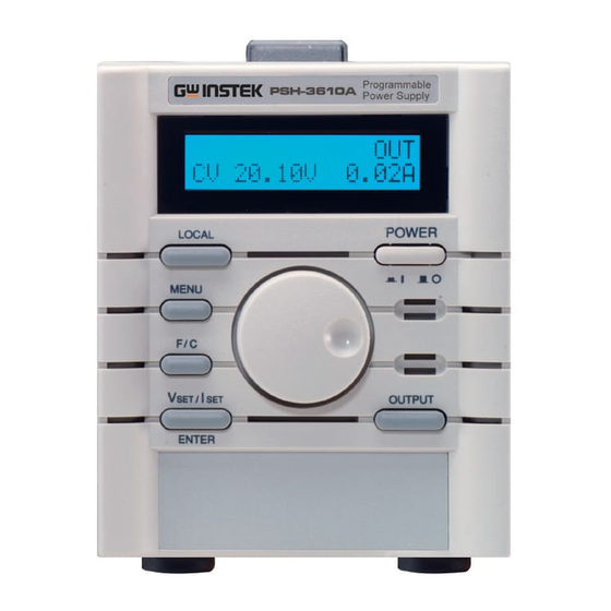
Programmable Power Supply
PSH series
USER MANUAL
ISO-9001 CERTIFIED MANUFACTURER
Related Manuals for GW Instek PSH series
Summary of Contents for GW Instek PSH series
-
Page 1
Programmable Power Supply PSH series USER MANUAL ISO-9001 CERTIFIED MANUFACTURER… -
Page 2
This manual contains proprietary information, which is protected by copyrights. All rights are reserved. No part of this manual may be photocopied, reproduced or translated to another language without prior written consent of Good Will company. The information in this manual was correct at the time of printing. However, Good Will continues to improve products and reserves the rights to change specification, equipment, and maintenance procedures at any time without notice. -
Page 3: Table Of Contents
Safety Symbols ………. 6 Safety Guidelines ……..6 Power cord for the United Kingdom ….9 PSH Overview ……….10 Main Features ……….. 12 PSH Series Lineup ……..13 Package Contents ……..14 Front Panel ……….16 Rear Panel ……….18 Display ………… 19 Setup …………21…
-
Page 4
PSH User Manual Buzzer sound Setting …….. 52 Remote Operation ……… 53 Interface Selection ……..54 Command Syntax ……..58 Command Set ………. 59 Calibration ………… 62 Calibration Preparation ……63 Entering calibration mode ……64 Output Voltage calibration ……65 Output Current calibration…… -
Page 5: Safety Instructions
Safety Instructions afety Instructions This chapter contains important safety instructions that must be followed when operating PSH and when keeping it in storage. Read the following before any operation to insure safety and to keep the best condition for PSH. Safety Symbols ………
-
Page 6: Safety Symbols
PSH User Manual Safety Symbols These safety symbols may appear in this manual or on PSH. Warning: Identifies conditions or practices that could result in injury or loss of life. WARNING Caution: Identifies conditions or practices that could result in damage to PSH or to other CAUTION properties.
-
Page 7: Fuse
Safety Instructions category II. Measurement category IV is for measurement performed at the source of low-voltage installation. Measurement category III is for measurement performed in the building installation. Measurement category II is for measurement performed on the circuits directly connected to the low voltage installation.
-
Page 8: Operation Environment
PSH User Manual Location: Indoor, no direct sunlight, dust free, Operation almost non-conductive pollution (Note below) Environment Relative Humidity: < 85% WARNING Altitude: < 2000m Temperature: 0°C to 40°C Input Breaker Capacity: Over 20A (PSH-3630A) This is a Class A product which may cause radio interference in a domestic environment.
-
Page 9: Power Cord For The United Kingdom
Safety Instructions Power cord for the United Kingdom When using PSH in the United Kingdom, make sure the power cord meets the following safety instructions. NOTE: This lead / appliance must only be wired by competent persons WARNING: THIS APPLIANCE MUST BE EARTHED IMPORTANT: The wires in this lead are coloured in accordance with the following code: Green/ Yellow:…
-
Page 10: Psh Overview
Remote control interface equipped with SCPI command set and Lab-View Driver facilitates ATE software development. This chapter describes PSH series features and appearances in a nutshell. Main Features ………. 12 Main features 360W …………. 13 Series lineup 720W ………….
-
Page 11
PSH Overview descriptions Menu mode display ……..20… -
Page 12: Main Features
PSH User Manual Main Features 4 models: 20V/18A, 36V/10A, 36V/20A and Performance 36V/30A High power factor with PFC control High efficiency power conversion Compact size, light weight Constant voltage operation Operation Constant current operation Output On/Off control …
-
Page 13: Psh Series Lineup
PSH Overview PSH Series Lineup PSH series consist of the following 12 models with various output voltage and current ratings. For the detailed specifications, see page72. 360W PSH-2018A 20V, 18A (Mainframe only) PSH-3610A 36V, 10A 720W PSH-3620A 36V, 20A (Mainframe +…
-
Page 14: Package Contents
PSH User Manual Package Contents Check the contents before using PSH series. Contact your local dealer in case there is a missing item. Main unit Cable gland AC input cable Terminal cover AC power input cord …
-
Page 15
PSH Overview Package Contents (cont.) Terminal cover Output connection kit Output cable screw User manual (this document) Manual Programming manual … -
Page 16: Front Panel
PSH User Manual Front Panel Shows the output and the configuration status. 1 LCD Display See page19 for details. 2 Power Switch Sets parameters. Turn right: increase, turn left: 3 Wheel knob decrease. Turns the output On or Off. When On, the 4 Output “OUT”…
-
Page 17
PSH Overview Switches between voltage setting mode and 5 Vset/ Iset/ current setting mode, or confirm the entered Enter key value in the menu mode (see page45). Vset (edit Voltage) Iset (edit Current) SET 2.58V 2.01A SET 2.58V 2.01A Switches the editing location and resolution: 6 F/C (Fine/ before (coarse) or after (fine) the decimal point. -
Page 18: Rear Panel
PSH User Manual Rear Panel Connect the output line shield (page25) and 1 Ground the remote sensing line shield (page33). Terminal Connect DUT (Device Under Test). For 2 Output details, see page24. Terminal Connect the feedback line to compensate for 3 Sense Terminal cable loss.
-
Page 19: Display
PSH Overview Display Display mode Editing mode Default display RMT ADRS OCP OUT 10.10V 36.10A SET 10.10V 36.10A RMT: remote control mode (Nothing): panel operation mode Not available in editing mode ADRS: RS-232 or GPIB address (available in remote control) Not available in editing mode OCP: Output Current Protection On (Nothing): Output Current Protection Off…
-
Page 20
PSH User Manual Display (cont.) The following displays appear when pressing the Menu mode MENU Menu key . To move to the next display configuration, press the Menu key repeatedly. When inactive for more than 5 seconds, the display goes back to the default mode. (Default display) OCP OUT 2.58V… -
Page 21: Setup
Setup etup This chapter describes load configurations and setup procedures. Follow these instructions to properly install PSH series. AC Power Cable Assembly ……22 AC power cable assembly AC power cable requirement ….. 23 Remote Sensing and Local Sensing …. 24…
-
Page 22: Ac Power Cable Assembly
PSH User Manual AC Power Cable Assembly Put the power cable through the cable gland 1 Cable gland + and the terminal cover, screw them together. Terminal Cover Screw the wire onto the AC input terminal. Note 2 Cable wire + the wire color: Neutral (white), GND (green), and Terminal Line (black).
-
Page 23: Ac Power Cable Requirement
Setup AC power cable requirement Here is the AC power cable specification, in case of using cables other than the attached one. ≤ 3m Cable length KSS or PG-2013 Cable gland Model: SJT Cable type Type: 3 x 14 AWG stranded copper (recommended) Rating: 60°C min, 300V Diameter: 9.143~10.03 mm…
-
Page 24: Remote Sensing And Local Sensing
PSH User Manual Remote Sensing and Local Sensing Remote sensing compensates the cable loss between PSH and load, up to 0.5V. Use remote sensing whenever the load voltage has to be accurate. Local Sensing LOAD (default) Load > Output LOAD Setting –V Sense…
-
Page 25: Load / Remote Sensing Wire Selection
Setup Load / Remote Sensing Wire Selection The following instructions apply to both load wire and remote sensing wire, unless noted. Load wires must have enough current capacity Wire size (FOR to minimize cable loss and load line impedance. LOAD ONLY) Voltage drop across a wire should not excess 0.5V.
-
Page 26
PSH User Manual… -
Page 27: Load Configuration
Setup Load Configuration Select the appropriate configuration for the target application. For local sensing and remote sensing explanation, see the previous page. For connection guideline, see page25 (wire selection), page31 (load connection), page33 (remote sensing connection). Single PSH + single load Single Load + —OUT —IN…
-
Page 28: Multiple Loads + Local Sensing
PSH User Manual Single PSH + multiple Load Output current for each load follows the load Condition requirement. When the sum of the load current surpasses the rating, PSH automatically switches to CC (Constant Current) mode. Multiple —OUT —IN Loads + Local Load #1…
-
Page 29: Series Operation + Local Sensing
Setup Multiple PSH + single load (series operation) Up to four PSH series (with identical output Condition ratings) can be cascaded. Output voltage is the sum of the cascaded PSH. Output current is the same as a single PSH.
-
Page 30: Series Operation + Remote Sensing
PSH User Manual Series Operation (cont.) Series —OUT —IN Operation + PSH #1 Load +OUT Remote Sensing —Sense +Sense —OUT PSH #2 +OUT —Sense +Sense First PSH: Negative output → Negative load input Positive output → The next PSH negative output Negative sense →…
-
Page 31: Load Wire Assembly
Setup Load Wire Assembly Select the appropriate wire according to the 1. Wire guideline on page25. selection Replace the two screws on the output terminal 2. Terminal with the hex screw in the output connection kit. screw replacement Screw load wires to the terminal. 3.
-
Page 32
PSH User Manual Load Wire Assembly (cont.) Screw the output terminal cover to the rear 4. Terminal panel. cover assembly Connect the load wire shield to the rear panel 5. Wire shield ground connector. connection (recommended) -
Page 33: Remote Sensing Wire Assembly
Setup Remote Sensing Wire Assembly Select the appropriate wire according to the guideline on page25. The sense terminal is connected to the output Local sensing monitor terminal with bare wires. 1. Take off the wire jumpers. Remote Sensing 2. Screw wires to the sense (S) side. Do not screw remote sensing wires to the …
-
Page 34
PSH User Manual Remote Sensing Wire Assembly (cont.) To minimize noise effect, we recommend 5. Wire shield covering the remote sensing wire with ground connection shield and connect it to the ground terminal. An open remote sense circuit leads to output CAUTION level overshoot. -
Page 35: Functionality Check
Setup Functionality Check Check the PSH basic functionalities before operation. Preparation Output Voltage Check items OVP functionality Output Current OCP functionality Digital DC Voltage Accuracy: Equipment Multimeter <±0.1% Recommended model: GDM-8245, GDM-8246 Current Shunt Current range: >100A …
-
Page 36: Output Voltage & Ovp Check
PSH User Manual Output Voltage & OVP Check Connection PSH Series — Digital Multimeter Checking step 1. Power On PSH and connect the Multimeter Voltage measurement terminal. 2. Set Output Voltage and Output Current to the rating value. PSH-2018A (20V, 18A)
-
Page 37
Setup 4. Make sure the Multimeter shows no value (No output). OUTPUT 5. Press the Output key and turn On the output. The display changes into CV (Constant Voltage) mode and shows the OUT sign on the top CV 20.00V 18.00A right corner. -
Page 38: Output Current Check
PSH User Manual Output Current Check Connection Current Digital Multimeter PSH Series Shunt — Checking step 1. Power On PSH and connect the Multimeter/ Current Shunt terminal. 2. Set the Output Voltage and Current value to the rating. PSH-2018A (20V, 18A) Vset/Iset/Enter key …
-
Page 39: Ocp Check
Setup OCP Check Connection Current Digital Multimeter PSH Series Shunt — Checking step 1. Power On PSH and connect the Multimeter / Current Shunt terminal. 2. Set the Output Voltage and Current value to the rating. PSH-2018A (20V, 18A) Vset/Iset/Enter key ENTER …
-
Page 40
PSH User Manual Press the Vset/Iset/Enter key to confirm the setting. ENTER The OCP sign appears on the upper side of the display. CV 20.00V 18.00A OUTPUT 4. Press the Output key and turn On the output. 5. Make sure the display shows the error message. LOCAL Press the Local key to get… -
Page 41: Rack Mounting (Optional)
Setup Rack Mounting (Optional) PSH can be mounted on standard 19 inch rack using GRA-403 rack mounting kit. Rack mounting kit contents Main bracket x 1 Front panel x 1 Large decoration board x 1 Medium decoration board x 2 Small decoration board x 2 Binding plate x 6 Handle x 2…
-
Page 42: (Optional) Rack Mounting Assembly
PSH User Manual Rack mounting assembly 1. Rack Confirm the rack mount layout. Make sure mounting there is a space between each PSH. Below is the layout example of rack mounting layout. 2. Decoration Once the layout is fixed, screw the decoration board boards to the front panel using M3 screws.
-
Page 43
Setup 4. Main bracket Fix the PSH to the main bracket using M3 assembly screws. Fix the front panel and the handle to the main bracket using M4 screws. -
Page 44: Panel Operation
PSH User Manual anel Operation This chapter describes the manual operations done at the front panel, together with the constant voltage/ constant current crossover characteristics. Menu Key Overview ……..45 Menu key overview Constant Voltage/ Constant Current Crossover CV/ CC Characteristic ……….
-
Page 45: Menu Key Overview
Panel Operation Menu Key Overview MENU Press the Menu key . To move to the next item, press the Menu key repeatedly. Default display OCP OUT 2.58V 2.01A Output Voltage Protection setting To set the value, use the wheel knob Set OVP To select the editing point (before * 21.10V…
-
Page 46: Constant Voltage/ Constant Current Crossover Characteristic
PSH User Manual Constant Voltage/ Constant Current Crossover Characteristic PSH series automatically switch between constant voltage mode and constant current mode, according to the load change. Constant Voltage When the load current is smaller than the limit (I PSH operates in Constant…
-
Page 47: Output Voltage Setting
Panel Operation Output Voltage Setting Operation 1. Press the Vset/ Iset key repeatedly to move the underline SET 2.58V 2.01A to the Voltage side. 2. Press the F/C key to move the underline before or after the SET 2.58V 2.01A decimal point.
-
Page 48: Output Current Setting
PSH User Manual Output Current Setting Operation 1. Press the Vset/ Iset key repeatedly to move the underline SET 2.58V 2.01A to the Current side. 2. Press the F/C key to move the underline before or after the SET 2.58V .01A decimal point.
-
Page 49: Ovp (Output Voltage Protection) Setting
Panel Operation OVP (Output Voltage Protection) Setting Set the OVP value MENU 1. Press the Menu key OCP OUT repeatedly until the OVP menu 2.58V 2.01A appears. Set OVP * 21.10V Set OVP 2. Press the F/C key to move the underline before or after the * 21.10V decimal point.
-
Page 50: Ocp (Output Current Protection) Setting
PSH User Manual OCP (Output Current Protection) Setting Turn the OCP On/Off MENU 1. Press the Menu key OCP OUT repeatedly until the OCP menu 2.58V 2.01A appears. Set OCP 2. Use the wheel knob to change Set OCP the status to ON (or OFF). 3.
-
Page 51: Display Contrast Setting
Panel Operation Display Contrast Setting Operation MENU 1. Press the Menu key OCP OUT repeatedly until the Contrast 2.58V 2.01A menu appears. Set Contrast 2. Use the wheel knob to change the contrast. Clockwise: increase, Counterclockwise: decrease. 5% ~ 95% Range Step…
-
Page 52: Buzzer Sound Setting
PSH User Manual Buzzer sound Setting Operation MENU 1. Press the Menu key OCP OUT repeatedly until the Buzzer menu 2.58V 2.01A appears. Set Buzzer 2. Use the wheel knob to change Set Buzzer the buzzer setting to ON (or OFF). 3.
-
Page 53: Remote Operation
Remote Operation emote Operation This chapter describes the IEEE 488.2 based remote control configuration, command syntax, and command set overview. For further descriptions and examples, refer to the programming manual. RS232 (Standard) ……..54 Interface configuration GPIB (Optional) ……..56 Interface functionality check …..
-
Page 54: Interface Selection
PSH User Manual Interface Selection RS232 (Standard) MENU Baud rate 1. Press the Menu key repeatedly until setting the Interface menu appears. OCP OUT 2.58V 2.01A Interface RS232 Baud Rate 9600 2. Use the wheel knob to select the baud rate.
-
Page 55
Remote Operation 1 2 3 4 5 Pin 2: TxD PC RS-232 pin Pin 3: RxD assignment Pin 5: GND Pin 1, 4, 6 ~ 9: No Connection 6 7 8 9 Null-modem connection, in which transmit PSH – PC (TxD) and receive (RxD) lines are crosslinked, is connection required. -
Page 56: Gpib (Optional)
PSH User Manual GPIB (Optional) Refer to the service manual for GPIB module installation. Note: The RS232 module has to be replaced with the GPIB module: they cannot be used together. MENU Address setting 1. Press the Menu key repeatedly until the Interface menu appears.
-
Page 57: Interface Functionality Check
Remote Operation Interface functionality check In the remote control mode, the display shows Remote mode “RMT” on the top left corner. The panel display operation is disabled. 0.05V 1.05A To enable panel operation, press the Local LOCAL . This also disconnects the remote control.
-
Page 58: Command Syntax
PSH User Manual Command Syntax The commands are fully compatible with IEEE488.2 (1992) standard and partially compatible with SCPI (1994) standard. :chan1:prot:curr <0/1> LF Example command 1: Command Header 2: Single space 3: Parameter 4: Message Terminator OR Message Separator Several command header elements (nodes) can be Command concatenated to form a complex command.
-
Page 59: Command Set
Remote Operation Command Set Commands are non-case sensitive. For more detailed information, refer to the Programming Manual which is downloadable from www.gwinstek.com.tw. General commands :chan1:curr? Returns the output current (unit: A). Range: 0.01~rating current :chan1:curr Sets the output current (unit: A). <0.01~rating>…
-
Page 60: Status Commands
PSH User Manual Status commands *cls Clears all event status registers (Output Queue, Operation Event Status, Questionable Event Status, Standard Event Status) *ese? Returns the ESER (Event Status Enable Register) contents. Example: 130→means ESER=10000010 *ese <0~255> Sets the ESER contents. Example: *ese 65→sets ESER to 01000001 *esr? Returns and clears the SESR (Standard Event…
-
Page 61: Miscellaneous Commands
Remote Operation Miscellaneous commands *idn? Returns the power supply ID as Manufacturer, Model No, Serial No, Firmware version. Example: GW.Inc,PSH-2018A,12345678,FW1.00 *opc? “1” is placed in the output queue when all the pending operations are completed. *opc Sets the operation complete bit (bit0) in SERS (Standard Event Status Register) when all the pending operations are completed.
-
Page 62: Calibration
PSH User Manual alibration Run calibration when the output exceeds the specification, or when the functionality check (page35) fails. To get the optimal result, make sure PSH is powered for at least 30 minutes before the calibration. Calibration Preparation ……63 Setup Entering calibration mode ……
-
Page 63: Calibration Preparation
Calibration Calibration Preparation At least 30 minutes of warm-up time Calibration condition Temperature: 23 ± 5 °C Relative Humidity: ≤ 80% Minimum/ Maximum Output Voltage Calibration items Minimum/ Maximum Output Current OVP functionality Digital DC Voltage Accuracy: Calibration …
-
Page 64: Entering Calibration Mode
PSH User Manual Entering calibration mode 1. Press the Local key for 5 Please enter the seconds. The password entry Password: 0 menu appears. 2. Enter the model number as the (PSH-2018A) password. Wheel knob changes the Please enter the digit.
-
Page 65: Output Voltage Calibration
Calibration Output Voltage calibration Connection PSH Series — Digital Multimeter Calibration step 1. Enter the Voltage calibration Calibration menu. See page64 for details. Voltage 2. Press the Vset/Iset/Enter Calibration Voltmin 0.00V and enter Minimum ENTER Voltage calibration mode. 3. Adjust the display value to the Multimeter reading: 0.02V…
-
Page 66
PSH User Manual 5. Adjust the display value to the Multimeter reading: Multimeter reading. 20.03V Wheel knob changes the value. Calibration F/C key moves the cursor Voltmax 20.03V before and after the decimal point. 6. Press the Vset/Iset/Enter Calibration to confirm the setting. ENTER Voltage The display goes back to the… -
Page 67: Output Current Calibration
Calibration Output Current calibration Connection Digital Multimeter Current PSH Series Shunt — Calibration step 1. Enter the Current calibration Calibration menu. See page64 for details. Current 2. Press the Vset/Iset/Enter Calibration CurrMax 18.00A and enter Maximum ENTER Current calibration mode.
-
Page 68
PSH User Manual 5. Adjust the display value to the Multimeter reading: 0.02A Multimeter / Current Shunt reading. Calibration Wheel knob changes the value. CurrMin 0.02A F/C key moves the cursor before and after the decimal point. 6. Press the Vset/Iset/Enter Calibration to confirm the setting. -
Page 69: Ovp Calibration
Calibration OVP Calibration Connection No connection required Calibration step 1. Enter the Voltage calibration Calibration menu. See page64 for details. 2. Press the Vset/Iset/Enter Calibration 100% . PSH calibrates OVP ENTER automatically. 3. The display goes back to the default calibration menu. Calibration 4.
-
Page 70: Faq
PSH User Manual The OVP value/ OCP status has not been changed. After editing OVP value and OCP status, press ENTER the Vset/Iset/Enter key to confirm. Otherwise the setting does not change. The front panel does not respond. When in remote control mode, PSH does not respond to panel operations.
-
Page 71
If there is still a problem, please contact your local dealer or GWInstek at www.gwinstek.com.tw / marketing@goodwill.com.tw. -
Page 72: Appendix
PSH User Manual ppendix Specifications The specifications apply under the following conditions: PSH is powered on for at least 30 minutes, within +20°C~+30°C. Common specification Recovery Time CV mode ≤ 2ms (50% step load change from 25%~75%) Response Time Voltage Up ≤…
-
Page 73
Appendix Operation: 0°C~40°C (32°F~104°F) Relative 85% RH (maximum), non condensing Humidity Installation Category II (for details, see page6) Pollution Degree 2 (for details, see page8) Storage −10°C~70°C, 70% RH (maximum) Condition Accessories User manual, Programming manual, Cable gland, AC power cord, AC input cover, O/P terminal cover… -
Page 74
PSH User Manual PSH-2018A/ 3610A Output PSH-2018A 20V, 18A PSH-3610A 36V, 10A Regulation Load ≤ 0.1% + 5mV (C.V.) Line ≤ 0.05% + 5mV Regulation Load ≤ 0.2% + 5mA (C.C.) Line ≤ 0.2% + 5mA Ripple & Noise Voltage (mVrms) ≤… -
Page 75
Appendix PSH-3620A Output PSH-3620A 36V, 20A Regulation Load ≤ 0.1% + 5mV (C.V.) Line ≤ 0.05% + 5mV Regulation Load ≤ 0.2% + 10mA (C.C.) Line ≤ 0.2% + 10mA Ripple & Noise Voltage (mVrms) ≤ 10mVrms, 100mVpp, 20Hz~20MHz Current (mArms) ≤… -
Page 76
PSH User Manual PSH-3630A Output PSH-3630A 36V, 30A Regulation Load ≤ 0.1% + 5mV (C.V.) Line ≤ 0.05% + 5mV Regulation Load ≤ 0.2% + 15mA (C.C.) Line ≤ 0.2% + 15mA Ripple & Noise Voltage (mVrms) ≤ 10mVrms, 100mVpp, 20Hz~20MHz Current (mArms) ≤… -
Page 77: Index
Appendix Index OCP …………. 39 output current ……..38 AC input output voltage ……..36 cable assembly ……..22 OVP …………. 36 cord requirement …….. 23 setup………… 35 terminal ……….18 fuse rating ……..7, 74, 75, 76 safety instruction ……… 7 calibration certificate ……….
-
Page 78
PSH User Manual check ……….. 36 safety guidelines ……….6 package contents ……..14 symbol ……….. 6 power supply UK power cord ……..9 safety instruction ……..7 sound setting ……….. 52 protection specification ……….72 OCP setting ……..50 storage environment OVP setting ……..
Подключение кабелей питания может показаться сложной задачей. Их немного, но все они разного дизайна и длины и, в зависимости от вашей модели и производителя, окрашены в самые разные цвета.
К счастью, нет причин для беспокойства: подключение кабелей блока питания – чрезвычайно простой процесс, который редко меняется!
Вам нужно испытать этот процесс только один раз, и вы сможете его повторять долгие годы! Кроме того, это только поначалу кажется пугающим.
Как только вы поймете, какой кабель что делает, вы поймёте, насколько всё просто и понятно на самом деле!

После этого небольшого введения, давайте начнём!
Силовые кабели блока питания – что есть что
В этой части мы сосредоточимся на стандартном блоке питания, который вы можете купить со склада в местном магазине.
Вы открыли упаковку, вынули блок питания и теперь смотрите на кучу разных кабелей и разъёмов.
Какова цель каждого кабеля, предложенного производителем?
24-контактный разъём питания ATX
24-контактный разъём, возможно, является самым важным, поскольку он обеспечивает материнскую плату всей необходимой мощностью для правильной работы.
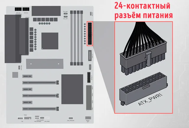
Для старых материнских плат требовался 20-контактный разъём, а для более новых – дополнительные четыре контакта. Поэтому этот разъём разделен на две части – 20-контактный и 4-контактный сегменты (чтобы обеспечить максимальную аппаратную совместимость).
Самый простой способ подключить 24-контактный кабель от блока питания – сначала вставить меньшую часть (4-контактную), а затем соответствующим образом выровнять более широкую часть и протолкнуть ее до упора, чтобы она была полностью выровнена.
После подключения он должен выглядеть как единый разъём – ничего не должно торчать или смещаться.
Как и большинство других разъёмов в этом списке, 24-контактный разъём имеет ключ и зажим, это означает, что он может работать только в одном направлении. Короче говоря, это отличная помощь для начинающих сборщиков ПК.
Соответствующий разъём для этого конкретного кабеля почти всегда находится с правой стороны материнской платы. Другими словами: вы не сможете пропустить это.
8-контактный (4+4) разъём питания ЦП
Этот конкретный разъём обеспечит процессор всей необходимой ему мощностью. Это его основная функция, и она настолько важна, насколько вы можете себе представить.
Разные процессоры имеют разные требования к питанию, что также отражается на выбранной вами материнской плате.
Ваша материнская плата будет иметь один из следующих вариантов:
- один 4-контактный разъём
- один 8-контактный разъём
- 8- и 4-контактный разъём
- или двойной 8-контактный разъём.
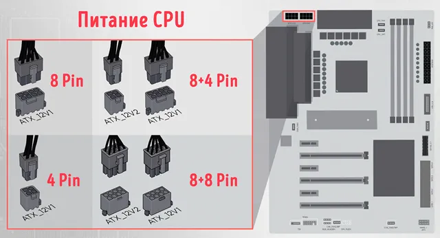
Материнские платы более высокого уровня – те, которые позволят вам разогнаться до нужного уровня – обеспечивают большую гибкость и, в свою очередь, могут вмещать более мощные процессоры (те, которым требуется много энергии).
Поскольку некоторые процессоры не так уж и прожорливы, этот кабель тоже разделён на две части, точнее, на два 4-контактных разъёма.
Вы всегда должны подключать оба, даже если ваш процессор не нуждается в такой большой мощности. Если, конечно, ваша материнская плата не имеет только один 4-контактный разъём.
Один 4-контактный разъём обеспечивает питание процессора до 155 Вт; комбинированный восьмиконтактный разъём обеспечивает мощность до 235 Вт.
Этот разъём также имеет вырез и ключ, поэтому его подключение к материнской плате не должно вызвать особых проблем. Сам разъём почти всегда расположен с левой стороны материнской платы, в самом верху.
6/8-контактный разъём питания видеокарты
Видеокарты различаются по размеру и мощности.
Модели начального уровня могут потреблять менее 75 Вт, поэтому они не требуют дополнительного питания – они получают всю необходимую энергию через материнскую плату и слот PCIe x16.
Умеренно мощные видеокарты потребляют более 100 Вт, поэтому они требуют дополнительного питания от блока питания.
Для этих моделей (а они самые распространенные) придётся подключать соответствующий 6-контактный (+75 Вт) или 8-контактный разъём (+150 Вт).
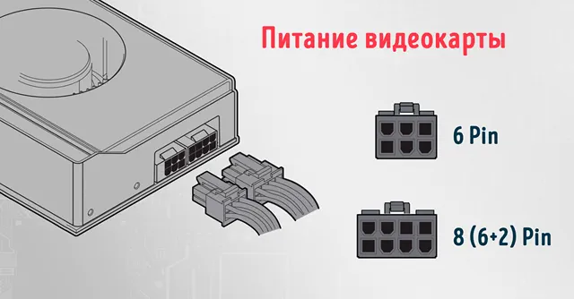
Для самых мощных графических процессоров на рынке требуется два 8-контактных разъёма, а некоторые модели от NVIDIA поставляются даже с 12-контактным разъёмом.
8-контактные разъёмы часто делятся на две части: 6-контактную и 2-контактную. Это сделано для того, чтобы обеспечить максимальную совместимость.
Разъём (в единственном или во множественном числе) всегда находится на самой видеокарте.
SATA (разъём питания Serial ATA)
Эти кабели предназначены для подачи питания на различные типы оборудования, включая жесткие диски, твердотельные накопители, внутренние оптические приводы CD/DVD, концентраторы вентиляторов, полосы RGB и т.д.
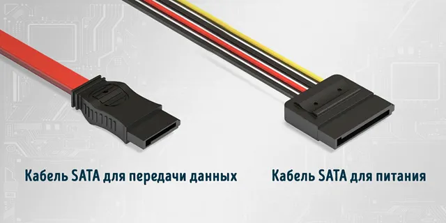
Их легко подключать, так как они имеют ключ только с одной стороны, это означает, что они являются одними из «самых простых» разъёмов.
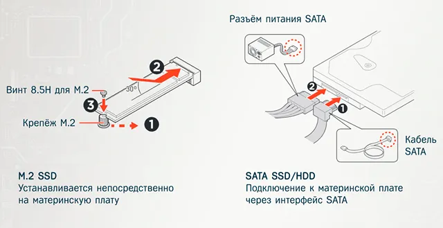
В зависимости от вашей сборки вы будете либо подключать несколько из них, либо не подключите ни одного. Всё больше пользователей переходят на формат M.2 SSD (по целому ряду причин).
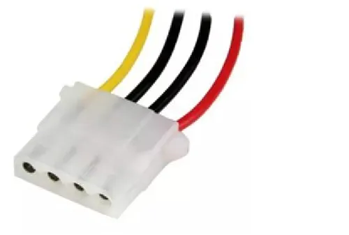
Подключение Molex
Разъёмы Molex довольно архаичны, но всё ещё используются для некоторых (более старых) аппаратных периферийных устройств.
Эти разъёмы когда-то играли роль, очень похожую на SATA, но с тех пор их использование было прекращено.
Тем не менее, в зависимости от вашей сборки и компонентов, с которыми вы работаете, вам могут понадобиться разъёмы Molex (крайне маловероятно, но всё же возможно), поэтому они определенно заслуживают небольшого внимания.
Если в вашем конкретном блоке питания нет кабелей/разъёмов Molex, вы всегда можете купить адаптер SATA-Molex и таким образом обойти проблему.
Часто задаваемые вопросы кабелях блока питания
Давайте рассмотрим несколько вопросов, которые могут у вас возникнуть относительно вашего блока питания и множества кабелей и разъёмов, выходящих из него:
Нужно ли подключать все кабели питания?
На самом деле, нет. Немодульные блоки питания поставляются со множеством различных кабелей и разъёмов, но не все из них необходимо подключать для правильной работы компьютера.
Должны быть подключены 24-контактный кабель для питания материнской платы, 4/8-контактный кабель для питания процессора, 6/8-контактный для видеокарты и, возможно, несколько SATA.
Вот и всё.
Какова задача блока питания?
Его задача довольно проста: снабжать ваши компоненты (и, по доверенности, ваш компьютер) питанием.
Без него ваш компьютер – каким бы красивым или дорогим он ни был – будет примерно таким же полезным, как мешок с кирпичами (даже бесполезнее).
Каждый отдельный компонент в вашей сборке имеет определенные требования к мощности. Они могут варьироваться от нескольких ватт (например, в случае твердотельных накопителей) до многих сотен в случае видеокарты и процессора.
И поэтому, естественно, чтобы передать электричество от розетки к вашим компонентам, ваш блок питания должен быть подключен с помощью ряда кабелей, каждый из которых имеет очень специфическое назначение.
К счастью, их число ограничено, и поэтому их легко классифицировать.
Должен ли я использовать модульный блок питания?
Это зависит от ваших личных предпочтений и общего бюджета.
Модульные блоки питания намного проще в использовании, потому что они предлагают сборщикам ПК роскошь подключения только тех кабелей, которые им нужны, и ничего больше.
Однако, они идут с премией. Если вы хотите, чтобы сборка вашего ПК была максимально «чистой» и имела наименьшее количество кабелей, то модульный блок питания не только рекомендуется, но и необходим.
Это их самое большое преимущество, но если у вас нет боковой панели из закаленного стекла и вам все равно, как выглядит внутренности вашего корпуса, то вы можете сэкономить, выбрав немодульный БП.
В качестве альтернативы вы можете использовать полумодульный блок питания. К ним постоянно подключены только самые важные кабели, так что это очень хорошая золотая середина.
Также стоит отметить, что полумодульные и полностью модульные блоки питания, как правило, имеют более высокое качество.
Если вы собираете «обычный» ПК – то есть такой, который можно отнести к категории «бюджетных», – то немодульный блок питания – это определенно то, что вам нужно.
Однако, если вы не жалеете средств и хотите купить самые лучшие компоненты, которые можно купить за деньги, то полу- или полностью модульный блок питания (тот, который энергоэффективен и имеет достаточное количество ватт) определенно должен быть на вершине вашего списка приоритетов.
Совместимы ли кабели питания процессора и видеокарты?
Точно нет! Они могут выглядеть одинаково, но они обеспечивают разную мощность и имеют совершенно разные варианты использования.
Только помните, что разъём ЦП разделен на две равные по размеру 4-контактные части.
Разъём графического процессора, с другой стороны, разделен на две неравные части: 6-контактный и 2-контактный сегменты, что позволяет легко отличить конкретный разъём от всех остальных.
Можно ли ошибиться при подключении кабелей питания?
Сложно. Кабели блока питания (или, скорее, разъёмы) хороши тем, что все они разработаны совершенно по-разному.
Другими словами: все они имеют разную конструкцию и никак не взаимозаменяемы.
Просто убедитесь, что все ваши разъемы полностью вставлены в соответствующие разъёмы, и всё готово!
Подключение кабелей питания может казаться непростой задачей для непосвященных.
К счастью, это не только просто, но и довольно прямолинейно! И как только вы сделаете это один раз, у вас будут все знания и опыт, которые сохранятся и будут полезны годы, если не на десятилетия вперёд!

Руководство пользователя
6. Приложения
143
www.qtech.ru
6.9 Кабель питания
Вид спереди разъёма питания 230В типа f IEC-320 C6 на задней панели:
Назначение контактов разъёма питания:
Контакт
Назначение
Е
L
N
Провод заземления
Фаза
Нейтральный провод