-
Page 1
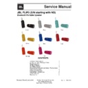
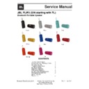
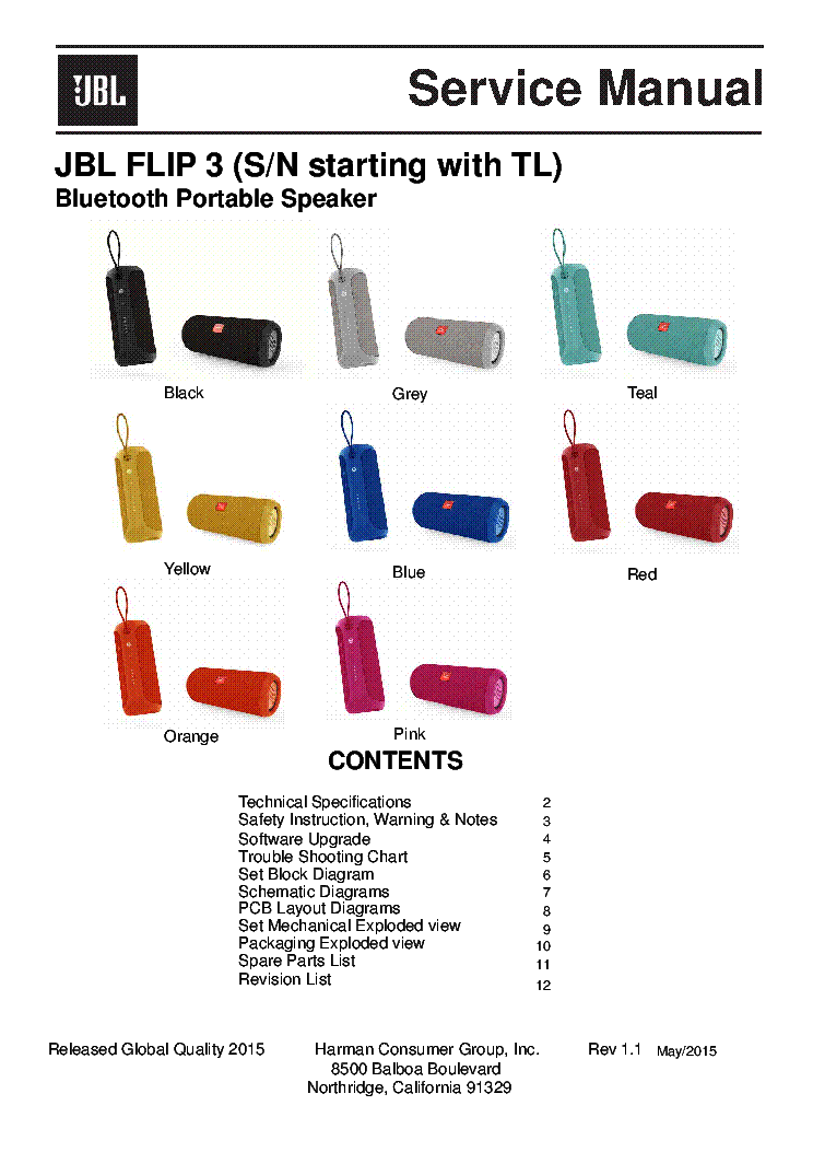
Released global quality 2015 harman consumer group, inc. Rev 1.3 8500 balboa boulevard northridge, california 91329 contents 2 3 6 7 technical specifications safety instruction, wa rning & notes reset instruction set block diagram set wiring diagram disassembly instruction schematic diagrams pcb lay…
-
Page 2: Technical Specifications
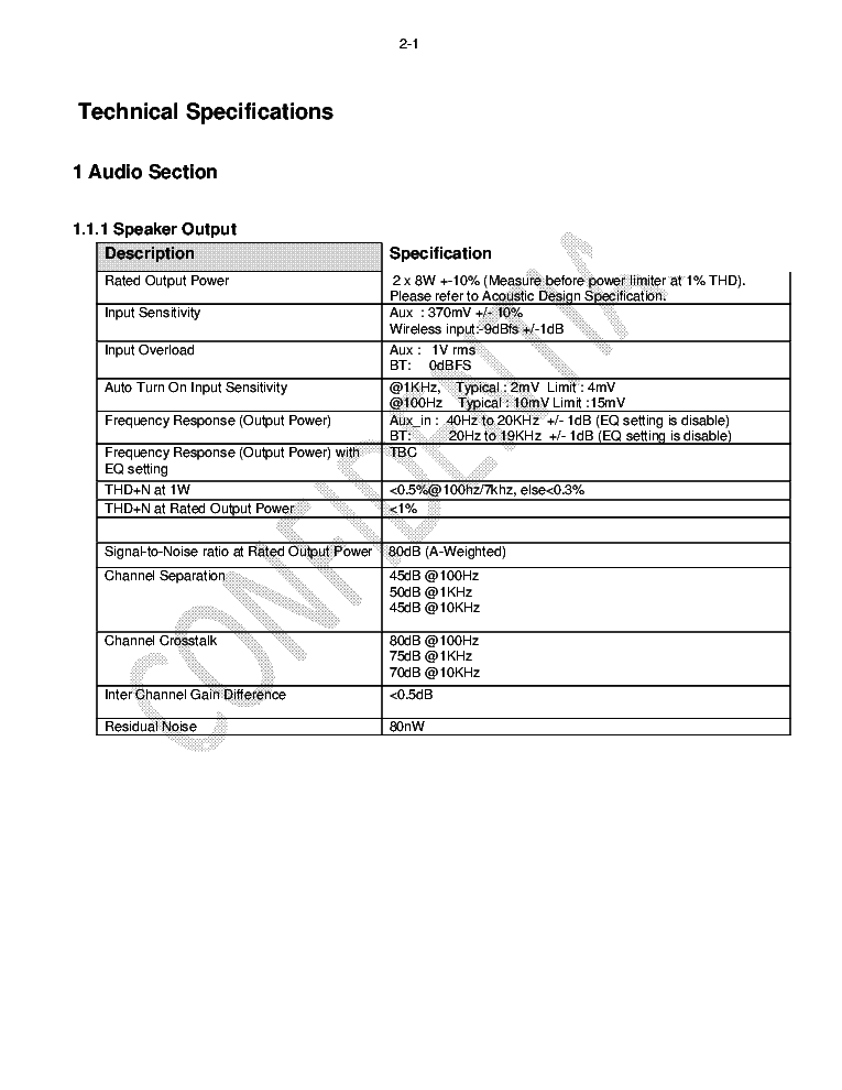
Technical specifications 1 audio section 1.1.1 speaker output description specification rated output power 2 x 8w +-10% (measure before power limiter at 1% thd). Please refer to acoustic design specification. Input sensitivity aux : 370mv +/- 10% wireless input:-9dbfs +/-1db input overload aux : 1v …
-
Page 3
1.1.2 microphone short circuit protection at output stage the amplifier should be protected so that no functional failure occurs when it is operated with a short across its output stage for 2 minutes. The amplifier should recover after removing the short condition. Dc offset protection the amplifier…
-
Page 4
1.3 bluetooth section 1.3.1 general description specification bluetooth standard version 4.1 frequency band 2.402 – 2.480 ghz host interface uart profile supported hfp (audio gateway and handsfree) a2dp (advanced audio distribution profile) avrcp (audio/video remote control profile) refer srd audio …
-
Page 5
1.3.4 transmitter performance @edr mode description specification relative transmit power @ antenna connector -2 to 1 dbm edr carrier frequency stability and modulation accuracy _ǵ 0 _.+] _ǵ l _.+] _ǵ 0 + ǵ l _.+] 506′(90 ‘(90 3hdn'(90 edr differential phase encoding >=99% 1.3.5 antenna performance …
-
Page 6
1.5 battery section 1.5.1 general specification description specification standard and method of measurement typical capacity 3000 mah charge voltage 4.2v output voltage typical : 3.7v limit : 4.2v no load condition cut off voltage typical : 3.0v limit : 2.8v standard charging method 0.5c constant c…
-
Page 7
1. Read these instructions. 2. Keep these instructions. 3. Heed all warnings. 4. Follow all instructions. 5. Do not use this apparatus near water. 6. Clean only with a dry cloth. 7. Do not block any ventilation openings.Install in accordance with the manufacturer’s instructions. 8. Do not install ne…
-
Page 8
Each precaution in this manual should be followed during servicing. Components identified with the iec symbol in the parts list are special significance to safety. When replacing a component identified with , use only the replacement parts designated, or parts with the same ratings or resistance, wa…
-
Page 9
Safety precautions the following check should be performed for the continued protection of the customer and service technician. Leakage current check measure leakage current to a known earth ground (water pipe, conduit, etc.) by connecting a leakage current tester between the earth ground and all ex…
-
Page 10
Hw reset: hold down the buttons “bluetooth & vol+ & vol-” for 2 seconds key in power on mode. Factory reset: hold down the buttons “phone & vol+” for 5 seconds in power on mode. 4.
-
Page 11
• bc8670 power led jbl link led bt led 10v bt antenna 5v 4ohm x2 usb upgrade d+/d- i2c charge status ba ery detect aux_in ti class d tpa3130 bt module(bm870) csr8670 (bt and mcu) power key and other keys v+/v- key ba ery leds micro usb 1.8a/0.5a/ 1a ba ery charger mp2637 input voltage detect mic1 on…
-
Page 12
Set wiring diagram 6.
-
Page 13
Toolslist 序号 名称 备注 序号 (number) 名称 (name) 备注 (remark) 小号电批头 1 小号电批头 screw driver (small) 2.0 (small) 2 中号电批头 screw 3 0 2 driver (middle) 3.0 一字螺丝刀(包美纹胶纸)’ 3 翘刀knife 一字螺丝刀(包美纹胶纸) — ’typeknife(wrappedbytape) 电批 4 electrical screw driver 1 2 3 4 7 — 1.
-
Page 14
1.先用翘刀沿着网罩与双色件间隙(按键面对 面)从上往下稍微翘起open the grille 2.再用翘刀沿着网罩与双 面)从上往下稍微翘起o 面)从上往下稍微翘起openthegrille carefullyusingscrewdriverbasedonthe direction. 面)从上往下稍微翘起o (closetobuttons)caref driverbasedonthed z型电批 4 用z型电批将产品双色件两头的4颗螺丝取下 2 1 4 3 4.用z型电批将产品双色件两头的4颗螺丝取下 (批头用2.0)takeoffthescrew…
-
Page 15
1 3 4 6 2 5 6 6.将灯板软胶垫撕扯取掉(底部备3m胶纸) 左辐射器 takeofftherubberpart 7.用电批将左右辐射器如 下(批头用2 0)take o 下(批头用2.0)takeo twoendsasshowed 2 3 1 4 9 将led灯板及按键板的13pin及6pin排线 1 4 9.将led灯板及按键板的13pin及6pin排线 (fpc),拔拆方法为将贴片fpc插座扣位90° 翻起后再将排线取出,再将pcb板取下(底部 备3m胶)take off the 13pin cable and 6pin 10 用电批将左右喇叭共计 备3m胶…
-
Page 16
12.先将腔体右侧3p及13p排线(fpc)及麦克 风2p aux板3p排插线从主板上取下 再用 13.将pcb板从腔体左边向 往另 方向推)推出后将 风2p、aux板3p排插线从主板上取下,再用 翘刀将pcb板两边固定黄胶翘开清理干净take offthe3pin,13pincable,2pinmiccable d 3 i i bl d th l th 往另一方向推)推出后将 线取下pushthepcba showedandthentake and3pinmiccable,andthencleanthe glueasshowediny…
-
Page 17
1 1 2 2 3 3 4 4 5 5 6 6 7 7 8 8 d d c c b b a a title number revision size a2 date: 2015/3/17 sheet of file: d:\e\..\amp(20150227).Schdoc drawn by: modsel 1 sdz 2 faultz 3 rinp 4 rinn 5 plimit 6 gvdd 7 gain/slv 8 gnd 9 linp 10 linn 11 mute 12 am2 13 am1 14 am0 15 sync 16 avcc 17 pvcc 18 pvcc 19 bsnl…
-
Page 18
Harman consumer group harman international shenzhen, guangdong, china size title rev. Sheet of scale: b drawing no. Created checked a b c d a b c 1 2 3 4 1 2 3 4 d date cad file: revision history rev eco checked date proprietary information — these documents and the information contained therein are…
-
Page 19
1 1 2 2 3 3 4 4 5 5 6 6 7 7 8 8 d d c c b b a a title number revision size a2 date: 2015/3/17 sheet of file: d:\e\..\io_expander(20150227).Schdoc drawn by: p12 15 p11 14 p10 13 gnd 12 p07 11 p06 10 p05 9 p04 8 p03 7 p02 6 p01 5 p00 4 /reset 3 a1 2 /int 1 p13 16 p14 17 p15 18 p16 19 p17 20 a0 21 scl …
-
Page 20
1 1 2 2 3 3 4 4 5 5 6 6 7 7 8 8 d d c c b b a a title number revision size a2 date: 2015/3/17 sheet of file: d:\e\..\key+led board(20150227).Schdoc drawn by: jbl_link_key agnd power white power bt blue led agnd battery >75% white agnd agnd agnd agnd agnd agnd battery 60-75% white battery 45-60% whit…
-
Page 21
1 1 2 2 3 3 4 4 5 5 6 6 7 7 8 8 d d c c b b a a title number revision size a2 date: 2015/3/17 sheet of file: d:\e\..\key1 board(20150114).Schdoc drawn by: agnd bt_key v- v+ phone agnd bt_rsset_in_1 agnd 10v c154 1uf 100k r167 100k r168 100k r169 nc r191 nc r192 nc r195 nc r196 1 2 3 4 5 6 j100 0.5s-…
-
Page 22
1 1 2 2 3 3 4 4 5 5 6 6 7 7 8 8 d d c c b b a a title number revision size a2 date: 2015/3/17 sheet of file: d:\e\..\power(20150105).Schdoc drawn by: n/ c 1 ch g 2 b oos t 3 csp 4 ba t t 5 agnd 6 olim 7 iset 8 ntc 9 fb 10 acok 11 reg 12 tm r 13 pw in 14 il im 15 vc c 16 vb 17 en 18 mode 19 vin 20 sy…
-
Page 23
1 1 2 2 3 3 4 4 5 5 6 6 7 7 8 8 d d c c b b a a title number revision size a2 date: 2015/3/17 sheet of file: d:\e\..\usb_socket(20150227).Schdoc drawn by: agnd 4 2 3 j301 pj-321b 1 2 3 4 j12 b 4b-ph-k-s c800 nc c801 esd0402v18c15 c802 esd0402v18c15 vbus 1 d- 2 d+ 3 id 4 gnd 5 sh ie d 0 con600 micro_…
-
Page 24
Layout diagram — main board 9.
-
Page 25
Layout diagram — usb board.
-
Page 26
Layout diagram — led board.
-
Page 27
Layout diagram — key board.
-
Page 28
Mechanical exploded view 10
-
Page 29
Spare parts list pos. No. Part number description 2 25104880202009 usb cover flip3 black nd 2 25104880202029 usb cover flip3 pink nd 2 25104880202019 usb cover flip3 grey nd 2 25104880202039 usb cover flip3 teal nd 2 25104880202049 usb cover flip3 blue nd 2 25104880202059 usb cover flip3 red nd 2 25…
-
Page 30
Revision list version 1.0 initial release for jbl flip3. Update on page 11 for grille ass’y part numbers. Version 1.1 add position number for part list on page 11 version 1. 2 grille ass’y p/n on page 29 updated. Version 1. 3.
-
Contents
-
Table of Contents
-
Bookmarks
Quick Links
JBL FLIP3 (S/N starting with ND)
Bluetooth Portable Speaker
Black
Yellow
Orange
Released Global Quality 2015
CONTENTS
Technical Specifications
Safety Instruction, Wa rning & Notes
Reset Instruction
Set Block Diagram
Set Wiring Diagram
Disassembly Instruction
Schematic Diagrams
PCB Layout Diagrams
Mechanical Exploded view
Spare Parts List
Revision List
Harman Consumer Group, Inc.
8500 Balboa Boulevard
Northridge, California 91329
Service Manual
Grey
Blue
Pink
Teal
Red
2
3
4
5
6
7
8
9
10
11
12
Nov./2015
Rev 1.3
Summary of Contents for JBL FLIP3
File Specifications:911/911445-flip3.pdf file (21 Apr 2023) |
Accompanying Data:
JBL FLIP3 Speakers PDF Service Manual (Updated: Friday 21st of April 2023 05:32:04 PM)
Rating: 4.3 (rated by 68 users)
Compatible devices: VT4880A, ARC CENTER, MEDIA 3, Party Box 200, LX500, G CINEMA, N500, MPro 400.
Recommended Documentation:
Service Manual (Text Version):
(Ocr-Read Summary of Contents of some pages of the JBL FLIP3 Document (Main Content), UPD: 21 April 2023)
-
4, 1.3 Bluetooth Section 1.3.1 General Description Specification Bluetooth Standard Version 4.1 Frequency Band 2.402 – 2.480 GHz Host Interface UART Profile Supported HFP (Audio Gateway and Handsfree) A2DP (Advanced Audio Distribution Profile) AVRCP (Audio/Video Remote Control Profile) Refer SRD Audio Codec SBC (Subband Codec) Data Rate 2.1Mbps (over the air) 300Kbps (over UART) Antenna Extern…
-
3, 1.1.2 Microphone Short Circuit Protection at Output Stage The amplifier should be protected so that no functional failure occurs when it is operated with a short across its output stage for 2 minutes. The amplifier should recover after removing the short condition. DC Offset Protection The amplifier with output power of higher than 50W per channel must ensure that no DC is available at its output in normal mode as…
-
18, Harman Consumer Group HARMA N INTERNATIONAL Shenzhen, Guangdong, China SIZE TITLE REV. SHEET O F SCALE: B DRAWING NO. CREATED CHECKED A B C D A B C 12 34 123 4 D DATE CAD FILE: REVISION HISTORY REV ECO CHECKED DATE PROPRIETARY INFORMATION — THESE DOCUMENTS AND THE INFORMATION CONTAINED THEREIN ARE PROPRIETARY AND ARE NOT TO BE REPRODUCED OR DISCLOSED TO OTHERS FOR MANUFACTURE OR ANY OTHER PURPOSE EXCEPT THOSE SPECIFICALLY AUT…
-
7, 1. Read these instructions. 2. Keep these instructions. 3. Heed all warnings. 4. Follow all instructions. 5. Do not use this apparatus near water. 6. Clean only with a dry cloth. 7. Do not block any ventilation openings.Install in accordance with the manufacturer’s instructions. 8. Do not install near any heat sources such as radiators, heat registers, stoves or other apparatus (including amplifiers) that produce heat. 9. …
-
6, JBL FLIP3 1.5 Battery Section 1.5.1 General Specification Description Specification Standard and Method of Measurement Typical Capacity 3000mAH Charge Voltage 4.2V Output Voltage Typical : 3.7V Limit : 4.2V No Load Condition Cut Off Voltage Typical : 3.0V Limit : 2.8V Standard Charging Method 0.5C Constant current charge to 4.2V (+/- 0.05V), then constant voltage 4.2V charge till charge current decline to <= 0.05C Charging Time 3 hour …
-
2, Technical Specifications 1 Audio Section 1.1.1 Speaker Output Description Specification Rated Output Power 2 x 8W +-10% (Measure before power limiter at 1% THD). Please refer to Acoustic Design Specification. Input Sensitivity Aux : 370mV +/- 10% Wireless input:-9dBfs +/-1dB Input Overload Aux : 1V rms BT: 0dBFS Auto Turn On Input Sensitivity @1KHz, Typical : 2mV Limit : 4mV @100Hz Typical : 10mV Limit…
-
11, • BC8670 Power Led JBL Link LED BT led 10V BT Antenna 5V 4ohm x2 USB upgrade D+/D- I2C Charge status Baery detect Aux_in TI Class D TPA3130 BT Module(BM870) CSR8670 (BT and MCU) Power key and other keys V+/V- key Baery LEDs Micro USB 1.8A/0.5A/ 1A Baery Charger MP2637 Input Voltage Detect Mic1 On/off switch On/Off switch 3.7V 3000mAH Boost MPS MP3428 LDO SD35 3.3V Control chargingg Audio Signal: Power Signal: Control Signal: On/off …
-
5, 1.3.4 Transmitter Performance @EDR Mode Description Specification Relative transmit power @ antenna connector -2 to 1 dBm EDR Carrier Frequency Stability and Modulation Accuracy _ǵ 0 _.+] _ǵ L _.+] _ǵ 0 + ǵ L _.+] 506 ‘(90 ‘(90 3HDN ‘(90 EDR differential phase encoding >=99% 1.3.5 Antenna Perform…
-
22, JBL FLIP3 1 1 2 2 3 3 4 4 5 5 6 6 7 7 8 8 D D C C B B A A Title Number RevisionSize A2 Date: 2015/3/17 Sheet of File: D:\e\..\power(20150105).SchDoc Drawn By: N/C 1 CHG 2 BOOST 3 CSP 4 BATT 5 AGND 6 OLIM 7 ISET 8 NTC 9 FB 10 ACOK 11 REG 12 TMR 13 PWIN 14 ILIM 15 VCC 16 VB 17 EN 18 MODE 19 VIN 20 SYS 21 SW 22 PGND 23 PGND 24 U9 MP2637 BST 1 SDR 2 OUT 3 EN 4 MODE 5 SENSE 6 SW 7 SW 8 PGND 9 PGND 10 IN 11 VDD 12 COMP 13 FB 14 SS 15 AGND 16 PGND 17 PGND …
-
10, JBL FLIP3 HW reset: Hold down the buttons “Bluetooth & VOL+ & VOL-” for 2 seconds key in Power On mode. Factory reset: Hold down the buttons “Phone & VOL+” for 5 seconds in Power On mode. 4
… -
1, Released Global Quality 2015 Harman Consumer Group, Inc. Rev 1.3 8500 Balboa Boulevard Northridge, California 91329 CONTENTS 2 3 6 7 Technical Specifications Safety Instruction, Wa rning & Notes Reset Instruction Set Block Diagram Set Wiring Diagram Disassembly Instruction Schematic Diagrams PCB Layout Diagrams Mechanical Exploded view Spare Parts List Revision List Nov./2015 4 5 9 10 11 12 Ser…
-
8, Each precaution in this manual should be followed during servicing. Components identified with the IEC symbol in the parts list are special significance to safety. When replacing a component identified with , use only the replacement parts designated, or parts with the same ratings or resistance, wattage, or voltage that are designated in the parts list in this manual. Leakage-current or resistance measurements must be made to determine that exposed parts are acceptably insulated from the su…
-
17, 1 1 2 2 3 3 4 4 5 5 6 6 7 7 8 8 D D C C B B A A Title Number RevisionSize A2 Date: 2015/3/17 Sheet of Fil e: D:\e\..\AMP(20150227).SchDoc Drawn By: MODSEL 1 SDZ 2 FAULTZ 3 RINP 4 RINN 5 PLIMIT 6 GVDD 7 GAIN /S LV 8 GND 9 LINP 10 LINN 11 MUTE 12 AM2 13 AM1 14 AM0 15 SYNC 16 AVCC 17 PVCC 18 PVCC 19 BSNL 20 OUTNL 21 GND 22 OUTPL 23 BSPL 24 GND 25 BSNR 26 OUTNR 27 GND 28 OUTPR 29 BSPR 30 PVCC 31 PVCC 32 Thermal Pad 33 U6 TPA3130D2 L_in_3…
-
JBL FLIP3 User Manual
-
JBL FLIP3 User Guide
-
JBL FLIP3 PDF Manual
-
JBL FLIP3 Owner’s Manuals
Recommended: ASMB-825I-00A1E, Lumix DMC-LX5, Hob, SDS-P3042
Links & Tools
Operating Impressions, Questions and Answers:
DOWNLOAD JBL FLIP 3 Service Manual ↓ Size: 3.8 MB | Pages: 33 in PDF or view online for FREE

- Model
- FLIP 3
- Pages
- 33
- Size
- 3.8 MB
- Type
- Document
- Service Manual
- Brand
- Device
- Audio
- File
- flip-3.pdf
- Date
- 2018-11-20
JBL FLIP 3 Service Manual ▷ View online
Released Global Quality 201
Harman Consumer Group, Inc.
Rev 1.
8500 Balboa Boulevard
CONTENTS
2
3
6
7
Technical Specifications
Safety
s
e
t
o
N
&
g
n
i
n
r
a
W
,
n
o
i
t
c
u
r
t
s
n
I
Set
Diagram
Schematic Diagrams
PCB Layout Diagrams
Exploded view
Spare Parts List
Revision List
./201
4
5
9
10
11
12
Service Manual
JBL FLIP3 (S/N starting with ND)
Bluetooth Portable Speaker
Black
Grey
Orange
Blue
Red
Yellow
Teal
Pink
8
Disassembly Instruction and Splash Proof process
Technical Specifications
1 Audio Section
1.1.1 Speaker Output
Description
Specification
Rated Output Power
2 x 8W +-10% (Measure before power limiter at 1% THD).
Please refer to Acoustic Design Specification.
Input Sensitivity
Aux : 370mV +/- 10%
Wireless input:-9dBfs +/-1dB
Input Overload
Aux : 1V rms
BT: 0dBFS
Auto Turn On Input Sensitivity
@1KHz, Typical : 2mV Limit : 4mV
@100Hz Typical : 10mV Limit :15mV
Frequency Response (Output Power)
Aux_in : 40Hz to 20KHz +/- 1dB (EQ setting is disable)
BT: 20Hz to 19KHz +/- 1dB (EQ setting is disable)
Frequency Response (Output Power) with
EQ setting
TBC
THD+N at 1W
<0.5%@100hz/7khz, else<0.3%
THD+N at Rated Output Power
<1%
Signal-to-Noise ratio at Rated Output Power 80dB (A-Weighted)
Channel Separation
45dB @100Hz
50dB @1KHz
45dB @10KHz
Channel Crosstalk
80dB @100Hz
75dB @1KHz
70dB @10KHz
Inter Channel Gain Difference
<0.5dB
Residual Noise
80nW
2-1
1.1.2 Microphone
Short Circuit Protection at Output Stage
The amplifier should be protected so that no functional failure
occurs when it is operated with a short across its output stage
for 2 minutes. The amplifier should recover after removing the
short condition.
DC Offset Protection
The amplifier with output power of higher than 50W per channel
must ensure that no DC is available at its output in normal mode
as well as abnormal/faulty condition mode.
Thermal Protection
There should not be any breakdown or activation of any
protection circuit during the entire thermal profile test. Refers to
the Thermal Profile test stated in Reliability Test Plan for
Multimedia Powered Speaker System.
Output Power Duration
FTC requirement:
Warm-up or preconditioning period at 1/8 power for 1 hour,
followed by 5 minutes of continuous Rated Output Power (ROP).
Channels in the same frequency range are tested at ROP.
Subwoofer is tested separately.
IEC requirement :
Output power distortion limited of 60 sec
Short-term maximum output power of 1 sec
Long-term maximum output power of 1 minutes
Temperature-limited output power infinitely
1.2 USB Section
Reference : USB-IF USB 2.0 Electrical Test Specification Version 1.03 dated January, 2005
2-2
1.3 Bluetooth Section
1.3.1 General
Description
Specification
Bluetooth Standard
Version 4.1
Frequency Band
2.402 – 2.480 GHz
Host Interface
UART
Profile Supported
HFP (Audio Gateway and Handsfree)
A2DP (Advanced Audio Distribution Profile)
AVRCP (Audio/Video Remote Control Profile)
Refer SRD
Audio Codec
SBC (Subband Codec)
Data Rate
2.1Mbps (over the air)
300Kbps (over UART)
Antenna
External
Certification
CE, FCC, BQE
1.3.2 Transmitter Performance @BDR Mode
Description
Specification
Maximum Transmit Power @ antenna
connector
0 ~ 4dBm(class II)
Power Control
Maximum Power Step
<=8dB
Minimum Power Step
>=2dB
Initial Carrier Frequency Shift
+/- 75KHz
Carrier Drift
— Drift
Rate
—
Drift (Single Slot Packet)
—
Drift (Three Slot Packet)
—
Drift (Five Slot Packet)
+/- 20KHz/50us
+/- 25KHz
+/- 40KHz
+/- 40KHz
Modulation Characteristic
— F1avg
—
F2 Max Pass rate
— F1/F2
Ratio
140KHz – 175KHz
>=115KHz
>= 0.8
1.3.3 Receiver Performance
Description
Specification
Single Slot Sensitivity @ <=0.1%BER
<= -85dBm
Multiple Slot Sensitivity @ <=0.1%BER
<= -85dBm
Maximum Input Level @ <= 0.1% BER
>= -20dBm
2-3
- DOWNLOAD JBL FLIP 3 Service Manual ↓ Size: 3.8 MB | Pages: 33 in PDF or view online for FREE
- Here you can View online or download the Service Manual for the JBL FLIP 3 in PDF for free, which will help you to disassemble, recover, fix and repair JBL FLIP 3 Audio. Information contained in JBL FLIP 3 Service Manual (repair manual) includes:
- Disassembly, troubleshooting, maintenance, adjustment, installation and setup instructions.
- Schematics, Circuit, Wiring and Block diagrams.
- Printed wiring boards (PWB) and printed circuit boards (PCB).
- Exploded View and Parts List.
Found More:
FLIP 3 Service Manuals
| Preview | Download | Pages | Size |
|---|---|---|---|
|
|
FLIP 3 (serv.man2) Service Manual |
31 | 1.94 MB |
RANDOM:
- CDX-4000RV (serv.man2)
- KV-G14F2 (serv.man4)
- LC-37P55E (serv.man55)
- 32LV3500-ZA, 32LV3551-ZD, 32LV369C-ZD, 32LV3550-ZB, 32LV355A-ZB, 32LV355C-ZB, 32LV355N-ZB, 32LV355U-ZB (CHASSIS:LD01U)

JBL FLIP 3 SM
Type: (PDF)
Size
2.1 MB
Page
30
Category
AUDIO
SERVICE MANUAL
If you get stuck in repairing a defective appliance
download
this repair information for help. See below.
Good luck to the repair!
Please do not offer the downloaded file for sell only
use it for personal usage!
Looking for similar jbl manual?
Document preview [1st page]
Click on the link for free download!
Document preview [2nd page]
Click on the link for free download!
Please tick the box below to get download link:
- Also known:
JBL FLIP
- If you have any question about repairing write your question to the Message board. For this no need registration.
- If the site has helped you and you also want to help others, please Upload a manual, circuit diagram or eeprom that is not yet available on the site.
Have a nice Day! - Please take a look at the below related repair forum topics. May be help you to repair.
Warning!
If you are not familiar with electronics, do not attempt to repair!
You could suffer a fatal electrical shock! Instead, contact your nearest service center!
Note! To open downloaded files you need acrobat reader or similar pdf reader program. In addition,
some files are archived,
so you need WinZip or WinRar to open that files. Also some files are djvu so you need djvu viewer to open them.
These free programs can be found on this page: needed progs
If you use opera you have to disable opera turbo function to download file!
If you cannot download this file, try it with CHROME or FIREFOX browser.
Relevant AUDIO forum topics:
Sziasztok! Az aktív erősítős hordozható szerkezet már fél hangerőn is eléggé zörög, csattog, mély hangoknál ez már nagyon zavaró. Megnéztem és a készülék két végén lévő passzív basszus membrán közepén van egy kerek alumínium lap, ami a gumihoz van ragasztva. Ennek a ragasztásnak a széle már 2-4 mm mélyen elengedte, ezért nagy mozgások esetén az alu és a gumi már erősen csattogó hangot ad. Próbáltam egy kis erős gumiragasztót tűvel a kialakult résbe bekenni, ezzel a megoldással egy ideig jó volt, de mostanra még jobban elvált az egész. Valaki javított már ilyet, vagy csak teljes cserével lehetne ezt megoldani?
Sziasztok!
Szedett már szét valaki ilyet?
Mert én megakadtam vele.
Eljutottam odáig, hogy a külső burkolatot le tudom hámozni róla.
Azon a felén ahol a kezelőszervek vannak nem jutok előrébb, a gumi részét le tudom szedni de a nyák lap nem jön le. Van a nyákon két lyuk, de nincs alatta csavar, viszont feszegetésre sem akar elválni a műanyagtól.
Szerintem alatta vannak a csavarok amik «összetartják».
Melegíteni nem merem, mert a nyákra fóliával van felragasztva a «nyomógomb» az a szokásos rugós fém.
Youtube-on ez a típus nincs fent csak egy régebbi, és nem szeretném széttörni.
Akksit kellene cserélni benne, tehát nem akarom rosszabbá tenni mint amilyen most.
Köszi,
Krisztián
Sziasztok!
Kedvenc kis masinám cserben hagyott… nem akar rendesen dolgozni. Ugyebár ennek bejövő jel nélkül ki kellene kapcsolnia, de nem teszi. Ami még zavaróbb, hogy «LFE» bemenetről szinte csak sugdolózik.
Lehet tud valaki így «távgyógyítással» segíteni. :help:
Üdv, Z.
Lentebb a megoldás. Ami a kikapcsolást illeti, nos összerakás után az is rendben. Vélhetően nem ártott, hogy helyére kerültek az árnyékolások, stb.
Köszönöm mindenkinek a segítséget! :beer:
Üdvözlet mindenkinek!
Hozzám került ez a szörnyedvény,ami egy házimozi erősítő de sajnos semmi nincs meg hozzá csak mélyláda ami magában foglalja az erősítőt,szükség lenne még hozzá a hangfalakra meg egy távirányitó vevőre ami jack csatival csatlakozik a ládához(lehet ennek hiánya miatt villog???).Hibajelenség,hogy áram alá helyezve az elején lévő ledes kijelző egy része villog kivéve a standby led ami folyamatosan világít.Ebben szeretnék segítséget kérni,hogy ismeri valaki ezt a típust?Hogyan tudnám életre kelteni vagy valóban hibás?
Előre is köszönöm
Similar manuals:
If you want to join us and get
repairing help
please sign in or sign up by completing a simple electrical test
or write your question to the Message board without registration.
You can write in English language into the forum (not only in Hungarian)!
E-Waste Reduce


