Руководство по ремонту и обслуживанию дизельных двигателей Hino (J05C, J05C-TD, J08C-TP, J08C-TR, S05C, S05C-B, S05C-TA, S05C-TB, S05D)
Руководство по ремонту двигателей Hino & Toyota J05C (5,3 л с системой снижения токсичности), J05C-TD (5,3 л с турбонаддувом и электронным управлением ТНВД), J05D (4,7 л с турбонаддувом и системой «Common Rail»), J05E-TE (5,1 л с турбонаддувом), J05E-TC/TD (5,1 л с турбонаддувом и системой «Common Rail»), J08C-TP, J08C-TR (8,0 л с турбонаддувом и электронным управлением ТНВД), S05C (4,6 л с электронным управлением), S05C-B (4,6 л), S05C-TA (4,6 л с турбонаддувом), S05C-TB (4,6 л с турбонаддувом и системой «Common Rail») и S05D (4,9 л с электронным управлением), устанавливаемых на автомобили:
- Hino Dutro
- Hino Ranger
- Toyota Dynа / ToyoAce
- экскаваторы New Holland E215B / E265B / E385B
- экскаваторы Kobelco SK200 / 210 / 250 / 260 / 330 / 350
- а также на различную спецтехнику.
Руководство содержит подробные сведения по техническому обслуживанию двигателей, ремонту и регулировке механизмов двигателя, систем смазки и охлаждения, топливной системы, системы турбонаддува и системы электрооборудования двигателя.
- Подробно рассмотрены различные типы топливных систем: с рядным ТНВД, с распределительным ТНВД и электронным управлением, с Common Rail, а также настройки и регулировки ТНВД и форсунок.
- Приведены сведения по диагностике электронных систем управления (диагностические коды неисправностей (DTC), и условия их возникновения и возможные причины, осциллограммы).
- Приведены разъемы и процедуры проверки сигналов на выводах блоков управления для различных модификаций двигателей — PinData.
- Приведены электросхемы систем управления двигателем, зарядки и запуска для некоторых моделей.
- В издание добавлена информация по двигателям J05E!
- Эта книга может быть использована при ремонте 5-цилиндровых двигателей Hino J07C, устанавливавшихся на Hino Ranger.
- Приведены возможные неисправности и методы их устранения, сопрягаемые размеры основных деталей и пределы их допустимого износа, рекомендуемые смазочные материалы и рабочие жидкости, необходимые для технического обслуживания.
- Описаны конструктивные изменения, которым подвергались узлы и агрегаты двигателей в процессе производства.
Книга предназначена для автовладельцев, персонала СТО и ремонтных мастерских.
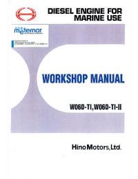
Руководство на английском языке по техническому обслуживанию и ремонту двигателей Hino моделей W06D-TI и W06D-TI-II.
- Автор: —
- Издательство: Hino Motors
- Год издания: —
- Страниц: 236
- Формат: PDF
- Размер: 3,4 Mb
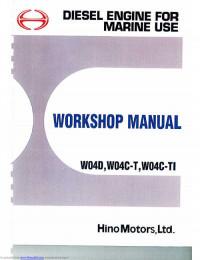
Руководство на английском языке по техническому обслуживанию и ремонту двигателей Hino моделей W04C-T, W04C-TI, W04D.
- Автор: —
- Издательство: Hino Motors
- Год издания: —
- Страниц: 216
- Формат: PDF
- Размер: 5,2 Mb
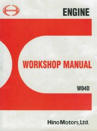
Руководство на английском языке по техническому обслуживанию и ремонту двигателей Hino модели W04D.
- Автор: —
- Издательство: Hino Motors
- Год издания: —
- Страниц: 205
- Формат: PDF
- Размер: 4,4 Mb
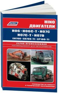
Руководство по техническому обслуживанию и ремонту двигателей Hino моделей H06, H06C-T, H06C, H07C-T, H07D, EH700, EH700-TI, EP100-TI.
- Автор: —
- Издательство: Легион-Автодата
- Год издания: —
- Страниц: 144
- Формат: —
- Размер: —
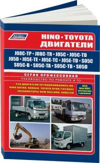
Руководство по техническому обслуживанию и ремонту двигателей Hino моделей J08C-TP, J08C-TR, J05C, J05C-TD, J05D, J05E-TE, J05E-TC, J05E-TD, S05C, S05C-B, S05C-TA, S05C-TB, S05D.
- Автор: —
- Издательство: Легион-Автодата
- Год издания: —
- Страниц: 190
- Формат: —
- Размер: —
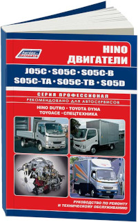
Руководство по техническому обслуживанию и ремонту двигателей Hino моделей J05C, S05C, S05C-B, S05C-TA, S05C-TB, S05D.
- Автор: —
- Издательство: Легион-Автодата
- Год издания: —
- Страниц: 120
- Формат: —
- Размер: —
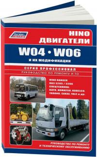
Руководство по техническому обслуживанию и ремонту двигателей Hino моделей W04 и W06.
- Автор: —
- Издательство: Легион-Автодата
- Год издания: —
- Страниц: 134
- Формат: —
- Размер: —
Диагностика. Ремонт. ТО
- Издательство: Легион-Aвтодата
- ISBN: 978-5-88850-381-2
- Число страниц: 176
- Формат: A4
- Переплет: Мягкий
- Двигатели: диз.: 4.6; 4.9; 5.3; 8.0;
HINO Двигатели J05C, J05C-TD, J08C-TP, J08C-TR, S05C, S05C-B, S05C-TA, S05C-TB, S05D. Устройство, техническое обслуживание и ремонт.
В руководстве дается подробное пошаговое описание процедур по ремонту и техническому обслуживанию дизельных двигателей HINO/TOYOTA J05C (5,3 л с системой снижения токсичности), J05C-TD (5,3 л с турбонаддувом и электронным управлением ТНВД), J08C-TP, J08C-TR (8,0 л с турбонаддувом и электронным управлением ТНВД), S05C (4,6 л с электронным управлением), S05C-B (4,6 л), S05C-TA (4,6 л с турбонаддувом), S05C-TB (4,6 л с турбонаддувом и системой «Common Rail») и S05D (4,9 л с электронным управлением).
Руководство содержит подробные сведения по ремонту и регулировке механизмов двигателя, сопрягаемые размеры основных деталей и пределы их допустимого износа, сведения по диагностике и регулировке ТНВД, систем запуска и зарядки.
Отдельные главы содержат информацию по проверке и диагностике электронной системы управления различных двигателей, в том числе осциллограммы и инструкции по использованию системы самодиагностики.
Приведена проверка системы через разъем электронного блока управления.
Дано описание принципа работы системы «Common Rail», приведены коды неисправности ее системы самодиагностики.
Приведены электросхемы систем управления двигателем, зарядки и запуска для некоторых моделей.
Книга предназначена для автовладельцев, персонала СТО и ремонтных мастерских.
Эта книга может быть использована при ремонте 5-ти цилиндровых двигателей Hino J07C, устанавливавшихся на Hino Ranger.
Руководство на русском языке по техническому обслуживанию и ремонту двигателей Hino моделей J08C-TP, J08C-TR, J05C, J05C-TD, J05D, J05E-TE, J05E-TC, J05E-TD, S05C, S05C-B, S05C-TA, S05C-TB, S05D.
Внимание! Нажимая на ссылку «скачать» Вы обязуетесь, после ознакомления, удалить скаченный файл со своего компьютера.
Всё содержимое сайта autosoftos.com взято из свободных источников, и также свободно распространяется.
Если это Вы являетесь автором данного материала, то, пожалуйста, свяжитесь с нами, для того чтобы обеспечить пользователям, приятную и удобную альтернативу, после ознакомления, покупки качественного «оригинала» непосредственно от издателя. Администрация сайта не несёт никакой ответственности за противоправные действия, и какой либо ущерб, понесённый правообладателями.

Руководство на английском языке по техническому обслуживанию и ремонту двигателей Hino моделей W06D-TI и W06D-TI-II.
- Автор: —
- Издательство: Hino Motors
- Год издания: —
- Страниц: 236
- Формат: PDF
- Размер: 3,4 Mb

Руководство на английском языке по техническому обслуживанию и ремонту двигателей Hino моделей W04C-T, W04C-TI, W04D.
- Автор: —
- Издательство: Hino Motors
- Год издания: —
- Страниц: 216
- Формат: PDF
- Размер: 5,2 Mb

Руководство на английском языке по техническому обслуживанию и ремонту двигателей Hino модели W04D.
- Автор: —
- Издательство: Hino Motors
- Год издания: —
- Страниц: 205
- Формат: PDF
- Размер: 4,4 Mb

Руководство по техническому обслуживанию и ремонту двигателей Hino моделей H06, H06C-T, H06C, H07C-T, H07D, EH700, EH700-TI, EP100-TI.
- Автор: —
- Издательство: Легион-Автодата
- Год издания: —
- Страниц: 144
- Формат: —
- Размер: —

Руководство по техническому обслуживанию и ремонту двигателей Hino моделей J08C-TP, J08C-TR, J05C, J05C-TD, J05D, J05E-TE, J05E-TC, J05E-TD, S05C, S05C-B, S05C-TA, S05C-TB, S05D.
- Автор: —
- Издательство: Легион-Автодата
- Год издания: —
- Страниц: 190
- Формат: —
- Размер: —

Руководство по техническому обслуживанию и ремонту двигателей Hino моделей J05C, S05C, S05C-B, S05C-TA, S05C-TB, S05D.
- Автор: —
- Издательство: Легион-Автодата
- Год издания: —
- Страниц: 120
- Формат: —
- Размер: —

Руководство по техническому обслуживанию и ремонту двигателей Hino моделей W04 и W06.
- Автор: —
- Издательство: Легион-Автодата
- Год издания: —
- Страниц: 134
- Формат: —
- Размер: —
Диагностика. Ремонт. ТО
- Издательство: Легион-Aвтодата
- ISBN: 978-5-88850-381-2
- Число страниц: 176
- Формат: A4
- Переплет: Мягкий
- Двигатели: диз.: 4.6; 4.9; 5.3; 8.0;
HINO Двигатели J05C, J05C-TD, J08C-TP, J08C-TR, S05C, S05C-B, S05C-TA, S05C-TB, S05D. Устройство, техническое обслуживание и ремонт.
В руководстве дается подробное пошаговое описание процедур по ремонту и техническому обслуживанию дизельных двигателей HINO/TOYOTA J05C (5,3 л с системой снижения токсичности), J05C-TD (5,3 л с турбонаддувом и электронным управлением ТНВД), J08C-TP, J08C-TR (8,0 л с турбонаддувом и электронным управлением ТНВД), S05C (4,6 л с электронным управлением), S05C-B (4,6 л), S05C-TA (4,6 л с турбонаддувом), S05C-TB (4,6 л с турбонаддувом и системой «Common Rail») и S05D (4,9 л с электронным управлением).
Руководство содержит подробные сведения по ремонту и регулировке механизмов двигателя, сопрягаемые размеры основных деталей и пределы их допустимого износа, сведения по диагностике и регулировке ТНВД, систем запуска и зарядки.
Отдельные главы содержат информацию по проверке и диагностике электронной системы управления различных двигателей, в том числе осциллограммы и инструкции по использованию системы самодиагностики.
Приведена проверка системы через разъем электронного блока управления.
Дано описание принципа работы системы «Common Rail», приведены коды неисправности ее системы самодиагностики.
Приведены электросхемы систем управления двигателем, зарядки и запуска для некоторых моделей.
Книга предназначена для автовладельцев, персонала СТО и ремонтных мастерских.
Эта книга может быть использована при ремонте 5-ти цилиндровых двигателей Hino J07C, устанавливавшихся на Hino Ranger.
Двигатели HINO J05C, J05C-TD, J08C-TP, J08C-TR, S05C, S05C-B, S05C-TA, S05C-TB, S05D: Устройство, техническое обслуживание и ремонт
Тема в разделе «Устройство автомобиля», создана пользователем AnyMe, 20 май 2015.
-
Двигатели HINO J05C, J05C-TD, J08C-TP, J08C-TR, S05C, S05C-B, S05C-TA, S05C-TB, S05D: Устройство, техническое обслуживание и ремонт
Издательство: Легион-Автодата
Жанр: Устройство и системы автомобиляКачество: Хорошее
Страниц: 190
Формат: pdf, fb2, epubРуководство по ремонту, обслуживанию и устройству дизельных двигателей Hino / Toyota J05C (5,3 л с системой снижения токсичности), J05C-TD (5,3 л с турбонаддувом и электронным управлением ТНВД), J08C-TP, J08C-TR (8,0 л с турбонаддувом и электронным управлением ТНВД), S05C (4,6 л с электронным управлением), S05C-B (4,6 л), S05C-TA (4,6 л с турбонаддувом), S05C-TB (4,6 л с турбонаддувом и системой Common Rail) и S05D (4,9 л.с. электронным управлением). Пособие включает в себя подробные сведения по ремонту и регулировке механизмов и узлов двигателя Хино, сопрягаемые размеры основных деталей и пределы их допустимого износа, сведения по диагностике и регулировке ТНВД, систем запуска и зарядки. Отдельные главы содержат информацию по проверке и диагностике электронной системы управления различных двигателей, в том числе осциллограммы и инструкции по использованию системы самодиагностики. Также в мануале приведена проверка системы через разъем электронного блока управления. Дано описание принципа работы системы Common Rail, приведены коды неисправности ее системы самодиагностики. Представлены электросхемы систем управления двигателем Хайно, зарядки и запуска для некоторых моделей. Настоящее пособие может быть использовано при ремонте 5-ти цилиндровых двигателей Hino J07C, устанавливавшихся на Hino Ranger. Книга будет полезна автовладельцам, механикам, сотрудникам СТО и ремонтных мастерских.
Вложения:
- Похожие книги
-
Toyota Dyna/Toyoace, Hino Dutro: Модели с 1999 года выпуска с дизельными двигателями J05C (5,3), J05D (4,7), N04C (4,0), S05C (4,6), S05D (4,9). Руков
Поделиться этой страницей

В руководстве дается подробное пошаговое изложение процедур по ремонту и техническому обслуживанию дизельных моторов HINO/TOYOTA J05C (5, 3 л с системой снижения токсичности), J05C-TD (5, 3 л с турбонаддувом и электронным управлением ТНВД), J08C-TP, J08C-TR (8, 0 л с турбонаддувом и электронным управлением ТНВД), S05C (4, 6 л с электронным управлением), S05C-B (4, 6 л), S05C-TA (4, 6 л с турбонаддувом), S05C-TB (4, 6 л с турбонаддувом и системой «Common Rail») и S05D (4, 9 л с электронным управлением). Руководство содержит подробные данные по ремонту и регулировке механизмов мотора, сопрягаемые размеры основных деталей и пределы их возможного износа, данные по диагностике и регулировке ТНВД, систем запуска и зарядки. Отдельные главы содержат информацию по проверке и диагностике электронной системы управления разных моторов, в том числе осциллограммы и инструкции по применению системы самодиагностики. Приведена проверка системы через разъем электронного блока управления. Дано изложение тезиса работы системы «Common Rail», приведены коды неисправности ее системы самодиагностики.Приведены электрические схемы систем управления мотором, зарядки и запуска для некоторых моделей. Издание (руководство, мануал, пособие) будет полезно для владельцев автомобилей и водителей , персонала станций технического обслуживания и автосервисов.Эта книга может быть использована при ремонте 5-ти цилиндровых моторов Hino J07C, устанавливавшихся на Hino Ranger.
Формат: А4.
Дизельные двигатели: 4.6; 4.9; 5.3; 8.0.
Переплёт: Мягкий.
Страниц: 192 шт.
Вес: 0.425 кг.
сравнить
| ISBN | цена | ед. изм. | купить | |
|---|---|---|---|---|
| 978-5-88850-381-2 | 990 р. | шт. |
Купить |

1 935 р.
Руководство по ремонту и техническому обслуживанию. Двигатели Cummins ISL, ISLe, ISC, ISCe, QSC8.3, QSL9Коды неиправностей

1 470 р.
Руководство Двигатели Cummins N14 Plus (обслуживание и ремонт)

880 р.
Руководство Mercedes-Benz, SsangYong дизельные двигатели ОМ 601, ОМ 602, ОМ 603, ОМ 604, ОМ 605, ОМ 606 и их модификации

1 060 р.
Руководство по ремонту и техническому обслуживанию двигателей Mitsubishi 6D14, 6D14-Т, 6D15-Т, 6D16, 6D17, Hyundai D6BR. Устройство двигателей

650 р.
Руководство Toyota двигатели 1HD-FTE, 1HD-FT, 1HZ, 1PZ Устройство, Техническое Обслуживание и ремонт
Перед заменой предохранителя определите причину перегрузки и устраните ее.
Заменять предохранитель нужно таким, который рассчитан на такую же силу тока, что предусмотрена изготовителем. Никогда не устанавливайте предохранитель с большим номиналом по силе тока, что был у оригинального: превышение допустимой тока в цепи может привести к повреждению элементов цепи или пожару.
Плавкая вставка
Плавкая вставка работает в основном так же, как плавкий предохранитель. Плавкая вставка представляет собой короткий кусок изолированного провода, который устанавливается последовательно в защищаемую цепь.
Для проверки плавкой вставки применяется универсальный тестер электрических цепей или пробник. Перед заменой плавкой вставки определите и устраните причину перегрузки цепи.
Номинал по силе тока вновь устанавливаемой вставки должен быть равен номиналу оригинальной вставки. В таблице даны номиналы плавких вставок, применяемых на автомобиле.
Реле
Расположение источника питания и электрической нагрузки может быть таким, что провода, соединяющие их, и выключатель цепи становятся слишком длинными, что вызывает заметное падение напряжения (1).
|
Models |
1INDEX |
ENGINE 3-1-1 |
|
|
J08C-TP and J08C-TR |
|||
|
3-228E-05 |
3
CHAPTER 3
ENGINE
Models: J08C-TP and J08C-TR
|
TROUBLESHOOTING ……………………………………………………… |
3- 1-3 |
|
SPECIAL TOOLS ……………………………………………………………. |
3- 2-1 |
|
ENGINE OVERHAUL CRITERIA ………………………………………. |
3- 3-1 |
|
DISMOUNTING THE ENGINE ASSEMBLY ………………………… |
3- 4-1 |
|
REMOVAL OF THE ENGINE COMPONENT PARTS …………… |
3- 5-1 |
|
CAMSHAFT HOUSING AND CYLINDER HEAD …………………. |
3- 6-1 |
|
CRANKSHAFT FRONT END, OIL PAN, FLYWHEEL AND |
|
|
FLYWHEEL HOUSING …………………………………………………….. |
3- 7-1 |
|
TIMING GEAR ………………………………………………………………… |
3- 8-1 |
|
PISTON, CRANKSHAFT AND CYLINDER BLOCK …………….. |
3- 9-1 |
|
LUBRICATING SYSTEM ………………………………………………….. |
3- 10-1 |
|
COOLING SYSTEM …………………………………………………………. |
3- 11-1 |
|
FUEL SYSTEM ……………………………………………………………….. |
3- 12-1 |
|
AIR INTAKE AND EXHAUST SYSTEM ……………………………… |
3- 13-1 |
|
ENGINE CONTROL SYSTEM …………………………………………… |
3- 14-1 |
|
ELECTRICAL PARTS ………………………………………………………. |
3- 15-1 |
|
AIR COMPRESSOR AND POWER STEERING PUMP ………… |
3- 16-1 |
|
INSTALLATION OF THE ENGINE COMPONENT PARTS ……. |
3- 17-1 |
|
ENGINE TUNE-UP ………………………………………………………….. |
3- 18-1 |
|
MOUNTING THE ENGINE ASSEMBLY ……………………………… |
3- 19-1 |
|
LIQUID GASKET AND APPLICATION POINTS ………………….. |
3- 20-1 |
|
POWER TAKE-OFF (IF FITTED) ………………………………………. |
3- 21-1 |

|
3-1-2 ENGINE |
Models |
1 page 1 |
|
|
J08C-TP and J08C-TR |
TROUBLESHOOTING (ENGINE)
|
Symptom |
Possible cause |
Remedy/Prevention |
||||||||||
|
Engine overheating |
Coolant |
|||||||||||
|
● |
Insufficient coolant …………………………………. |
Add coolant |
||||||||||
|
` |
● |
Defective thermostat ………………………………. |
Replace the thermostat |
|||||||||
|
● Overflow of coolant due to leakage of ………. |
Repair |
|||||||||||
|
exhaust into cooling system |
||||||||||||
|
● |
Damaged rubber hose ……………………………. |
Replace rubber hose |
||||||||||
|
● Coolant leakage due to deteriorated …………. |
Replace rubber hose |
|||||||||||
|
rubber hose |
||||||||||||
|
● Coolant leakage from coolant pump …………. |
Replace the coolant pump |
|||||||||||
|
● Coolant leakage from rubber hose …………… |
Retighten or replace clamp |
|||||||||||
|
connection |
||||||||||||
|
● Coolant leakage from cylinder head …………. |
Replace gasket |
|||||||||||
|
gasket |
||||||||||||
|
Coolant pump |
||||||||||||
|
● |
Bearing seizure ……………………………………… |
Replace |
||||||||||
|
● |
Damaged (corroded) vane ………………………. |
Replace vane |
||||||||||
|
Radiator |
||||||||||||
|
● Clogged with rust and scale …………………….. |
Clean radiator |
|||||||||||
|
● Clogged with iron oxide due to leakage …….. |
Clean coolant passage and |
|||||||||||
|
of exhaust into cooling system |
correct exhaust leakage |
|||||||||||
|
● |
Coolant leakage …………………………………….. |
Repair or replace radiator |
||||||||||
|
● |
Damaged cooling fan ……………………………… |
Replace cooling fan |
||||||||||
|
● Clogged radiator core due to mud or ………… |
Clean radiator |
|||||||||||
|
other debris |
||||||||||||
|
● Defective radiator cap pressure valve ………. |
Replace radiator cap |
|||||||||||
|
Abnormal combustion |
||||||||||||
|
● |
Incorrect injection timing …………………………. |
Adjust injection timing |
||||||||||
|
● |
Reduced injection pressure …………………….. |
Adjust injection pressure |
||||||||||
|
● |
Poor fuel……………………………………………….. |
Use good quality fuel |
||||||||||
|
● |
Poor nozzle spray ………………………………….. |
Adjust or replace nozzle |
||||||||||
|
● |
Unsatisfactory automatic timer…………………. |
Repair or replace timer |
||||||||||
|
advance angle |

|
1 page 1 |
|
|
Models J08C-TP and J08C-TR |
ENGINE 3-1-3 |
|
Symptom |
Possible cause |
Remedy/Prevention |
|||||||||
|
Engine overheating |
Other problems |
||||||||||
|
● |
Defective or deteriorated engine oil ………….. |
Change engine oil |
|||||||||
|
● |
Unsatisfactory operation of oil pump ………… |
Replace or repair |
|||||||||
|
● |
Insufficient oil ………………………………………… |
Add oil |
|||||||||
|
● |
Brake drag ……………………………………………. |
Adjust |
|||||||||
|
Severe operating conditions |
|||||||||||
|
● |
Lugging the engine ………………………………… |
Operate engine properly |
|
Excessive oil consumption |
Pistons, cylinder liners and piston rings |
||||||
|
● |
Wear of piston rings and cylinder liner ………. |
Replace piston rings and |
|||||
|
cylinder liner |
|||||||
|
● |
Worn, sticking or broken piston rings ………… |
Replace piston rings and |
|||||
|
cylinder liner |
|||||||
|
● |
Insufficient tension on piston rings ……………. |
Replace piston rings and |
|||||
|
cylinder liner |
|||||||
|
● |
Unsatisfactory break-in of piston rings ………. |
Replace piston rings and |
|||||
|
cylinder liner |
|||||||
|
● |
Unsuitable oil (viscosity too low) ………………. |
Change oil as required and |
|||||
|
replace piston rings and |
|||||||
|
cylinder liner |
|||||||
|
● |
Incorrectly fitted piston rings (upside down) .. |
Replace piston rings |
|||||
|
● |
Gaps of piston rings in line with each other .. |
Reassemble piston rings |
|||||
|
Valves and valve guides |
|||||||
|
● |
Worn valve stem ……………………………………. |
Replace valve and valve guide |
|||||
|
● |
Worn valve guide …………………………………… |
Replace valve guide |
|||||
|
● |
Incorrectly fitted valve stem seal ………………. |
Replace the stem seal |
|||||
|
● |
Excessive lubricant on rocker arm ……………. |
Check clearance of rocker arm |
|||||
|
and shaft |
|||||||
|
Excess oil feed |
|||||||
|
● |
Defective oil level gauge …………………………. |
Replace oil level gauge |
|||||
|
● |
Oil level too high ……………………………………. |
Drain excess oil |
|
3-1-4 ENGINE |
Models |
1 page 1 |
|
|
J08C-TP and J08C-TR |
|
Symptom |
Possible cause |
Remedy/Prevention |
||||||||
|
Excessive oil consumption |
Oil leakage from miscellaneous parts |
|||||||||
|
● Oil leakage from oil seal………………………….. |
Replace oil seal |
|||||||||
|
● Cracks or blowhole in cylinder block …………. |
Replace cylinder block |
|||||||||
|
● Oil leakage from connections of oil lines …… |
Tighten connections of oil lines |
|||||||||
|
● Oil leakage from oil cooler ………………………. |
Replace oil cooler |
|||||||||
|
● Oil leakage from oil pan gasket ……………….. |
Replace oil pan gasket |
|||||||||
|
● Oil leakage from O-ring …………………………… |
Replace O-ring |
|||||||||
|
Other problems |
||||||||||
|
● |
Overcooled engine …………………………………. |
Warm up engine before moving |
||||||||
|
(low temperature wear) |
vehicle |
|||||||||
|
Check cooling system |
NOTE: If oil consumption is excessive, the problems above will occur. Complaints from the customer are often related to such problems.
1.White smoke is emitted continuously when the engine is run at high speed.
2.White smoke is emitted only immediately after the engine speed is abruptly raised when idling.
3.The tail pipe is blackened with oil.
4.Oil leaks from the flanges of the exhaust manifold.
5.Lack of power.
6.Excessive blow-by gas.
|
Piston seizure |
Pistons, cylinder liners and piston rings |
|||
|
● Incorrect clearance between piston ………….. |
Replace piston, piston rings |
|||
|
and cylinder liner |
and cylinder liner |
|||
|
● Unsatisfactory installation of piston pin ……… |
Replace piston, piston rings, |
|||
|
cylinder liner and piston pin as |
||||
|
required |
||||
|
● |
Broken piston ring ………………………………….. |
Replace piston, piston rings |
||
|
and cylinder liner |
||||
|
● Difference in expansion due to use of ……….. |
Replace piston, piston rings |
|||
|
wrong piston |
and cylinder liner |
|||

|
1 page 1 |
|
|
Models J08C-TP and J08C-TR |
ENGINE 3-1-5 |
|
Symptom |
Possible cause |
Remedy/Prevention |
|||||||||||
|
Piston seizure |
Coolant |
||||||||||||
|
● |
Reduction in capacity of coolant pump ……… |
Replace the coolant pump |
|||||||||||
|
(due to vane corrosion) |
|||||||||||||
|
● |
Leakage of coolant…………………………………. |
Repair |
|||||||||||
|
● |
Insufficient coolant …………………………………. |
Add coolant |
|||||||||||
|
● |
Dirty coolant ………………………………………….. |
Clean and replace coolant |
|||||||||||
|
● |
Defective radiator …………………………………… |
Repair or replace the radiator |
|||||||||||
|
(coolant leakage, clogging) |
|||||||||||||
|
● |
Defective rubber hose (leakage) ………………. |
Replace rubber hose |
|||||||||||
|
● |
Defective thermostat ………………………………. |
Replace the thermostat |
|||||||||||
|
● |
Leakage of exhaust into cooling system ……. |
Repair |
|||||||||||
|
Operation |
|||||||||||||
|
● |
Abrupt stoppage of engine after running …… |
Operate engine properly |
|||||||||||
|
at high speed |
|||||||||||||
|
● |
Hill climbing using unsuitable gear …………… |
Select suitable gear |
|||||||||||
|
Oil |
|||||||||||||
|
● |
Insufficient oil ………………………………………… |
Add oil |
|||||||||||
|
● |
Dirty oil …………………………………………………. |
Change oil |
|||||||||||
|
● |
Poor quality oil ………………………………………. |
Replace with proper engine oil |
|||||||||||
|
● |
High oil temperature……………………………….. |
Repair |
|||||||||||
|
● |
Low oil pressure …………………………………….. |
Repair |
|||||||||||
|
● |
Defective oil pump …………………………………. |
Repair oil pump |
|||||||||||
|
● |
Reduced performance due to worn ………….. |
Replace oil pump |
|||||||||||
|
oil pump |
|||||||||||||
|
● |
Suction strainer sucking air ……………………… |
Add oil and/or repair strainer |
|||||||||||
|
Abnormal combustion |
|||||||||||||
|
● |
Use of defective fuel ………………………………. |
Change fuel |
|||||||||||
|
● |
Incorrect injection timing …………………………. |
Adjust injection timing |
|||||||||||
|
● |
Engine overheating ………………………………… |
See Symptom: “Engine |
|||||||||||
|
overheating” |
|||||||||||||
|
3-1-6 ENGINE |
Models |
1 page 1 |
|
|
J08C-TP and J08C-TR |
NOTE: If piston seizure occurs, the problems above will occur. Complaints from the customer are often related to these problems.
1.White smoke is emitted.
2.Lack of power
3.Excessive blow-by gas
|
Symptom |
Possible cause |
Remedy/Prevention |
||||||||||
|
Lack of power |
Injection pump |
Refer to “FUEL INJECTION |
||||||||||
|
…………………………………….. |
||||||||||||
|
PUMP” |
||||||||||||
|
Intake |
||||||||||||
|
● |
Clogged air cleaner ………………………………… |
Clean element or replace |
||||||||||
|
element |
||||||||||||
|
Overheating |
See Symptom: “Engine |
|||||||||||
|
……………………………………….. |
||||||||||||
|
overheating” |
||||||||||||
|
Fuel and nozzle |
||||||||||||
|
● |
Poor nozzle spray ………………………………….. |
Adjust or replace injection |
||||||||||
|
nozzle |
||||||||||||
|
● Nozzle clogged with carbon …………………….. |
Clean nozzle |
|||||||||||
|
● Wear or seizure of nozzle ……………………….. |
Replace nozzle |
|||||||||||
|
● Air in fuel system……………………………………. |
Repair and bleed air from fuel |
|||||||||||
|
system |
||||||||||||
|
● |
Clogged fuel filter …………………………………… |
Replace element |
||||||||||
|
● Use of poor fuel……………………………………… |
Use good quality fuel |
|||||||||||
|
Pistons, cylinder liners and piston rings |
||||||||||||
|
● Seized or wear of piston …………………………. |
Replace the piston, piston rings |
|||||||||||
|
and liner |
||||||||||||
|
● Worn or broken piston rings, ……………………. Replace piston rings, piston |
||||||||||||
|
piston and cylinder liner |
and liner |
|||||||||||

|
1 page 1 |
|
|
Models J08C-TP and J08C-TR |
ENGINE 3-1-7 |
|
Symptom |
Possible cause |
Remedy/Prevention |
|||||||||||
|
Lack of power |
Other problems |
||||||||||||
|
● Exhaust brake butterfly valve stuck…………… |
Replace or repair exhaust |
||||||||||||
|
in half-open position |
brake |
||||||||||||
|
● |
Connecting rod bent ……………………………….. |
Replace or repair connecting |
|||||||||||
|
rod |
|||||||||||||
|
● Exhaust pipe or muffler crushed ………………. |
Replace exhaust pipe or |
||||||||||||
|
(increased back-pressure) |
muffler |
||||||||||||
|
● Breakage of turbine or blower ………………….. |
Refer to TURBOCHARGER in |
||||||||||||
|
CHAPTER 51 |
|||||||||||||
|
Leakage of exhaust |
Head gasket |
||||||||||||
|
● |
Fatigued gasket (aging) ………………………….. |
Replace gasket |
|||||||||||
|
● |
Damage………………………………………………… |
Replace gasket |
|||||||||||
|
● |
Improper installation ……………………………….. |
Replace gasket |
|||||||||||
|
Head bolts |
|||||||||||||
|
● |
Loose bolts ……………………………………………. |
Tighten bolts |
|||||||||||
|
● |
Elongated bolts ……………………………………… |
Replace bolts |
|||||||||||
|
● Improper tightening torque or …………………… |
Tighten properly |
||||||||||||
|
tightening sequence |
|||||||||||||
|
Cylinder block |
|||||||||||||
|
● |
Cracking ……………………………………………….. |
Replace cylinder block |
|||||||||||
|
● |
Surface distortion …………………………………… |
Repair or replace |
|||||||||||
|
● Fretting of cylinder liner insertion portion …… |
Replace cylinder block |
||||||||||||
|
(insufficient projection of cylinder liner) |
|||||||||||||
|
Cylinder head |
|||||||||||||
|
● |
Cracking ……………………………………………….. |
Replace cylinder head |
|||||||||||
|
● |
Surface distortion …………………………………… |
Repair or replace |
|||||||||||
|
Cylinder liners |
|||||||||||||
|
● |
Cracking ……………………………………………….. |
Replace cylinder liner |
|||||||||||
|
● |
Corrosion………………………………………………. |
Replace cylinder liner |
|||||||||||
|
● Insufficient projection of cylinder liner ……….. |
Replace cylinder liner |
|
3-1-8 ENGINE |
Models |
1 page 1 |
|
|
J08C-TP and J08C-TR |
|
Symptom |
Possible cause |
Remedy/Prevention |
|||||||
|
Leakage of exhaust |
Other problems |
||||||||
|
● |
Incorrect injection timing …………………………. |
Adjust injection timing |
NOTE: If leakage of the exhaust occurs, the problems above will occur. Complaints from the customer are often related to these problems.
1.Lack of power.
2.The engine overheats.
3.The coolant is discolored.
|
Difficulty starting engine |
Electrical system |
|||||||
|
● |
Discharged battery …………………………………. |
Charge battery |
||||||
|
● Defective wiring in starter-circuit ………………. |
Repair wiring of starter |
|||||||
|
● Loose or open-circuit battery cable …………… |
Tighten battery terminal |
|||||||
|
connections or replace battery |
||||||||
|
cable |
||||||||
|
● |
Breakdown of starter ………………………………. |
Replace starter |
||||||
|
● |
Broken glow plug …………………………………… |
Replace |
||||||
|
Injection pump |
……………………………………… |
Refer to “FUEL INJECTION |
||||||
|
PUMP” |
||||||||
|
Air cleaner |
||||||||
|
● |
Clogged element ……………………………………. |
Clean the element or replace |
||||||
|
the element |
||||||||
|
Fuel system |
||||||||
|
● No fuel in tank ……………………………………….. |
Supply fuel |
|||||||
|
● |
Clogged fuel line ……………………………………. |
Clean fuel line |
||||||
|
● Air sucked into fuel system through ………….. |
Tighten fuel line connections |
|||||||
|
fuel line connections |
||||||||
|
● |
Clogged fuel filter …………………………………… |
Replace element |
||||||
|
● Loose connection in high-pressure line …….. |
Tighten sleeve nut of high |
|||||||
|
pressure line |
||||||||
|
● |
Water in fuel ………………………………………….. |
Drain and clean fuel system |
||||||

|
1 page 1 |
|
|
Models J08C-TP and J08C-TR |
ENGINE 3-1-9 |
|
Symptom |
Possible cause |
Remedy/Prevention |
|||||||||||
|
Difficulty starting engine |
Nozzles |
||||||||||||
|
● |
Seized nozzle………………………………………… |
Replace nozzle |
|||||||||||
|
● Broken or fatigued nozzle spring ……………… |
Replace spring |
||||||||||||
|
Oil system |
|||||||||||||
|
● Oil viscosity too high ………………………………. |
Use proper viscosity oil, or |
||||||||||||
|
install an oil immersion heater |
|||||||||||||
|
and warm up oil |
|||||||||||||
|
Other problems |
|||||||||||||
|
● |
Seized piston ………………………………………… |
Replace piston, piston rings, |
|||||||||||
|
and liner |
|||||||||||||
|
● |
Seized bearing ………………………………………. |
Replace bearing and crankshaft |
|||||||||||
|
● |
Reduced compression pressure ………………. |
Overhaul engine |
|||||||||||
|
● Ring gear damaged or worn ……………………. |
Replace the ring gear and/or |
||||||||||||
|
accelerator cable |
starter pinion |
||||||||||||
|
● Improperly adjusted or broken …………………. |
Adjust or replace the |
||||||||||||
|
accelerator cable |
|||||||||||||
|
Rough idling |
Injection pump |
…………………………………….. |
Refer to “FUEL INJECTION |
||||||||||
|
PUMP” |
|||||||||||||
|
Nozzles |
|||||||||||||
|
● |
Uneven injection pressure ………………………. |
Adjust |
|||||||||||
|
● |
Poor nozzle spray ………………………………….. |
Adjust or replace nozzle |
|||||||||||
|
● Carbon deposit on nozzle tip …………………… |
Remove carbon |
||||||||||||
|
● |
Seized needle valve ……………………………….. |
Replace nozzle |
|||||||||||
|
Engine proper |
|||||||||||||
|
● |
Improper valve clearance ……………………….. |
Adjust valve clearance |
|||||||||||
|
● Improper contact of valve seat …………………. |
Replace or repair valve and |
||||||||||||
|
valve seat |
|||||||||||||
|
● Idling speed too low ……………………………….. |
Adjust idling speed |
||||||||||||
|
● Coolant temperature too low ……………………. |
Warm up engine |
||||||||||||
|
● Compression pressure of cylinders…………… |
Overhaul engine |
||||||||||||
|
markedly different from one another |
|||||||||||||
|
3-1-10 ENGINE |
Models |
1 page 1 |
|
|
J08C-TP and J08C-TR |
|
Symptom |
Possible cause |
Remedy/Prevention |
||||||||||
|
Rough idling |
Other problems |
|||||||||||
|
● Clogged high pressure injection line …………. |
Replace line |
|||||||||||
|
● Leakage due to improper tightening …………. |
Tighten sleeve nut |
|||||||||||
|
of high pressure injection line |
||||||||||||
|
● Improperly adjusted or broken …………………. |
Adjust or replace accelerator |
|||||||||||
|
accelerator cable |
cable |
|||||||||||
|
● |
Engine seizure ………………………………………. |
Replace pistons, piston rings |
||||||||||
|
and liners |
||||||||||||
|
● |
Incorrect valve timing ……………………………… |
Replace camshaft |
||||||||||
|
Diesel knock |
Refer to “FUEL INJECTION |
|||||||||||
|
Injection pump……………………………………….. |
||||||||||||
|
PUMP” |
||||||||||||
|
Nozzles |
||||||||||||
|
● |
Incorrect injection pressure ……………………… |
Adjust |
||||||||||
|
● |
Poor nozzle spray ………………………………….. |
Adjust or replace nozzle |
||||||||||
|
● |
Sticking of nozzle …………………………………… |
Check and/or replace |
||||||||||
|
● Fatigued or broken nozzle spring …………….. |
Replace spring |
|||||||||||
|
Fuel system |
||||||||||||
|
● Use of poor fuel……………………………………… |
Use good quality fuel |
|||||||||||
|
● Fuel leakage into combustion chamber …….. |
Adjust nozzles |
|||||||||||
|
(during engine starting) |
||||||||||||
|
Other problems |
||||||||||||
|
● Excessively cooled or heated engine ……….. |
Warm up or cool engine |
|||||||||||
|
● |
Insufficient air intake ………………………………. |
Correct |
||||||||||
|
● |
Insufficient compression pressure ……………. |
Repair |
||||||||||
|
● Compression pressure leaks at ……………….. |
Replace head gasket |
|||||||||||
|
cylinder head gasket |
||||||||||||
|
● Improper valve clearance or valve sticking … |
Adjust or repair |
|||||||||||
|
● |
Tappet sticking ………………………………………. |
Replace tappet and camshaft |

|
1 page 1 |
|
|
Models J08C-TP and J08C-TR |
ENGINE 3-1-11 |
|
Symptom |
Possible cause |
Remedy/Prevention |
|||||||||||
|
Unusual engine noise |
Piston |
||||||||||||
|
● |
Wear of piston pin boss or piston pin ………… |
Replace piston and/or piston |
|||||||||||
|
pin |
|||||||||||||
|
● |
Seized, damaged, or worn piston pin ……….. |
Replace piston pin bushing. |
|||||||||||
|
bushing |
|||||||||||||
|
● |
Worn pistons or cylinder liners …………………. |
Replace piston or cylinder liner |
|||||||||||
|
● |
Damaged or seized piston ………………………. |
Replace piston and cylinder |
|||||||||||
|
liner |
|||||||||||||
|
● |
Foreign matter on top surface of the piston .. |
Remove foreign matter and |
|||||||||||
|
repair or replace piston, cylinder |
|||||||||||||
|
liner, and/or cylinder head |
|||||||||||||
|
Valve mechanism |
|||||||||||||
|
● |
Incorrect valve clearance ………………………… |
Adjust valve clearance |
|||||||||||
|
● |
Valve cotter out of place ………………………….. |
Replace valve cotter |
|||||||||||
|
● |
Seized valve stem ………………………………….. |
Replace valve and valve guide |
|||||||||||
|
● |
Broken valve …………………………………………. |
Replace valve |
|||||||||||
|
● |
Damaged rocker arm support ………………….. |
Replace rocker arm support |
|||||||||||
|
● |
Broken valve spring ……………………………….. |
Replace valve spring |
|||||||||||
|
Bearings seizure |
|||||||||||||
|
● |
Insufficient lubricating oil …………………………. |
Add oil |
|||||||||||
|
● |
Excessive or insufficient tightening of ……….. |
Retighten to specified torque |
|||||||||||
|
bearing housings |
|||||||||||||
|
● |
Pits and scratches on bearing surface ………. |
Replace bearing and crankshaft |
|||||||||||
|
● |
Oil film formed on back of bearing ……………. |
Replace bearing |
|||||||||||
|
● |
Improper installation of bearing ……………….. |
Replace bearing |
|||||||||||
|
● |
Reduction of spread dimension of bearing … |
Replace bearing |
|||||||||||
|
● |
Distorted bearing housing ……………………….. |
Replace or correct bearing |
|||||||||||
|
housing |
|||||||||||||
|
● |
Excessive oil clearance…………………………… |
Replace bearing |
|||||||||||
|
3-1-12 ENGINE |
Models |
1 page 1 |
|
|
J08C-TP and J08C-TR |
|
Symptom |
Possible cause |
Remedy/Prevention |
||||||
|
Unusual engine noise |
Various other parts |
|||||||
|
● Exhaust gas leakage from exhaust …………… |
Retighten joints |
|||||||
|
pipe joints |
||||||||
|
● Loosen or missing intake manifold …………… |
Retighten or replace |
|||||||
|
flange gasket |
||||||||
|
● Intake valve seating is not concentric ……….. |
Replace or correct the valve |
|||||||
|
and valve seat |
||||||||
|
● |
Intake gas leakage …………………………………. |
Retighten |
||||||
|
Other problems |
||||||||
|
● Loose cooling fan mounting bolts or …………. |
Tighten the fan and |
|||||||
|
fan pulley nut |
crankshaft pulley |
|||||||
|
● Lack of lubricating oil ……………………………… |
Lubricate |
|||||||
|
(coolant pump, valves, etc.) |
||||||||
|
● |
Worn timing gear ……………………………………. |
Replace the timing gear |
||||||
|
● Breakage of turbine or blower ………………….. |
Refer to TURBOCHARGER in |
|||||||
|
CHAPTER 51 |
NOTE: The items on this page concern unusual engine noise which is due to causes other than those given for diesel knock.

|
1 page 1 |
|
|
Models J08C-TP and J08C-TR |
ENGINE 3-1-13 |
(FUEL INJECTION PUMP)
|
Symptom |
Possible cause |
Remedy |
|||||||||
|
Engine does not start |
Fuel not reaching injection pump |
||||||||||
|
● Fuel lines clogged or damaged ………………… |
Clean or replace fuel lines |
||||||||||
|
● |
Fuel filter clogged ………………………………….. |
Clean or replace the filter |
|||||||||
|
element |
|||||||||||
|
● Air in fuel caused by improper …………………. |
Repair connections |
||||||||||
|
connections of fuel line between |
|||||||||||
|
fuel tank and feed pump |
|||||||||||
|
● Filter incorporated in inlet side …………………. |
Remove foreign material |
||||||||||
|
of feed pump clogged |
|||||||||||
|
● Faulty feed pump check valve …………………. |
Repair or replace it |
||||||||||
|
● Feed pump piston spring broken ……………… |
Replace it |
||||||||||
|
● Feed pump push rod or tappet sticking …….. |
Repair or replace it |
||||||||||
|
Fuel reaching injection pump |
|||||||||||
|
● Faulty connection of accelerator cable ……… |
Repair connection |
||||||||||
|
to pump adjusting lever |
|||||||||||
|
● Control rack faulty or sticking …………………… |
Repair it |
||||||||||
|
● |
Damaged camshaft bearing …………………….. |
Repair it |
|||||||||
|
● Plunger worn or sticking………………………….. |
Correct or replace it |
||||||||||
|
● Faulty connection of engine …………………….. |
Repair it |
||||||||||
|
stop cable to pump stop lever |
|||||||||||
|
Nozzle faulty |
|||||||||||
|
● Fuel leakage caused by loosened ……………. |
Inspect and tighten it |
||||||||||
|
nozzle holder |
|||||||||||
|
● Low opening pressure of nozzle ………………. |
Adjust it |
||||||||||
|
● Nozzle pressure spring broken ………………… |
Replace it |
||||||||||
|
● Nozzle needle sticking to nozzle body ………. |
Correct or replace it |
||||||||||
|
Pump out of timing |
|||||||||||
|
● Improperly retarded injection timing ………….. |
Correct injection timing |
||||||||||
|
● Incorrect timing caused by improper …………. |
Check engine timing and |
||||||||||
|
installation of pump |
correct it |
||||||||||
|
● Woodruff key for pump camshaft cut off. …… |
Replace it |
||||||||||
|
● |
Improper pre-stroke adjustment ……………….. |
Correct it to obtain specified |
|||||||||
|
injection timing |
|
3-1-14 ENGINE |
Models |
1 page 1 |
|
|
J08C-TP and J08C-TR |
|
Symptom |
Possible cause |
Remedy |
|||||||||
|
Engine starts and stops |
Fuel lines clogged ………………………………….. |
Clean or replace fuel lines |
|||||||||
|
Air in fuel caused by damaged |
Repair fuel lines or replace fuel |
||||||||||
|
fuel lines or improper connection of |
lines and gaskets |
||||||||||
|
fuel lines |
|||||||||||
|
Engine has low power |
Pump out of timing |
||||||||||
|
● |
Excessive advanced timing……………………… |
Check and correct it |
|||||||||
|
resulting in loud knocking |
|||||||||||
|
● |
Excessively retarded timing …………………….. |
Check and correct it |
|||||||||
|
resulting in black smoke |
|||||||||||
|
● Defective injection pump overflow valve ……. |
Repair or replace it |
||||||||||
|
● Feed pressure too low ……………………………. |
Repair the feed pump |
||||||||||
|
● Improper accelerator cable adjustment …….. |
Adjust it |
||||||||||
|
Nozzle faulty |
|||||||||||
|
● Fuel leakage from nozzle holder ………………. |
Check and repair nozzle holder |
||||||||||
|
● Bad nozzle spray characteristic ……………….. |
Repair or replace it |
||||||||||
|
● Loosened adjusting screw in nozzle …………. |
Adjust it |
||||||||||
|
holder, resulting in low opening pressure |
|||||||||||
|
● Nozzle pressure spring broken ………………… |
Replace it |
||||||||||
|
Pump faulty |
|||||||||||
|
● Fuel leakage from delivery valve ……………… |
Retighten the delivery valve |
||||||||||
|
holder |
holder if it is loosened or replace |
||||||||||
|
O-ring if the O-ring is defective |
|||||||||||
|
● Defective seat of delivery valve assembly …. |
Repair or replace it |
||||||||||
|
● Delivery valve spring broken ……………………. |
Replace the spring |
||||||||||
|
● |
Plunger worn …………………………………………. |
Replace it |
|||||||||
|
● Large spread in fuel delivery ……………………. |
Adjust it |
||||||||||
|
● Wear of tappet roller ………………………………. |
Replace the roller |
||||||||||
|
● Camshaft bearing worn or broken…………….. |
Replace it |
||||||||||
|
● Improper adjustment of governor ……………… |
Adjust it |
||||||||||
|
full load stopper screw |

|
1 page 1 |
|
|
Models J08C-TP and J08C-TR |
ENGINE 3-1-15 |
|
Symptom |
Possible cause |
Remedy |
|||||||||||
|
Excessive smoke |
Black smoke |
||||||||||||
|
● Excessive fuel delivery caused by ……………. |
Adjust fuel delivery on test stand |
||||||||||||
|
incorrect adjustment of full load |
|||||||||||||
|
stopper screw |
|||||||||||||
|
● Excessively advanced injection timing. ……… |
Correct it |
||||||||||||
|
● Large spread in fuel delivery ……………………. |
Adjust it |
||||||||||||
|
● Bad nozzle fuel spray characteristics ……….. |
Check and correct them |
||||||||||||
|
White smoke |
|||||||||||||
|
● Unused after glow system……………………….. |
Use it |
||||||||||||
|
● Improperly retarded injection timing ………….. |
Advance injection timing |
||||||||||||
|
● |
Water in fuel ………………………………………….. |
Check and clean fuel lines |
|||||||||||
|
● Glow plug not operating ………………………….. |
Check glow plug circuit. Refer |
||||||||||||
|
to ELECTRICAL EQUIPMENT |
|||||||||||||
|
in CHAPTER 20 |
|||||||||||||
|
Low idle speed |
Improper adjustment of throttle control knob |
Correct it |
|||||||||||
|
irregular |
Bad fuel spray characteristic of nozzles. …… |
Check and repair them |
|||||||||||
|
Incorrect injection timing …………………………. |
Correct it |
||||||||||||
|
Incorrect initial tension setting of………………. |
Adjust or replace it |
||||||||||||
|
idling spring or the spring broken. |
|||||||||||||
|
Control rack does not move smoothly……….. |
Disassemble pump and repair it |
||||||||||||
|
Large spread in fuel delivery ……………………. |
Adjust it |
||||||||||||
|
Plunger worn …………………………………………. |
Replace it |
||||||||||||
|
Governor linkage does not move smoothly… |
Correct it |
||||||||||||
|
Defective feed pump ………………………………. |
Disassemble and repair it |
||||||||||||
|
Engine always runs |
Accelerator cable sticking ……………………….. |
Check and correct it |
|||||||||||
|
at high speed |
Governor linkage sticking ……………………….. |
Disassemble and repair the |
|||||||||||
|
governor |
|||||||||||||
|
Control rack sticking……………………………….. |
Check and correct it |
||||||||||||
|
Loud knocking |
Improper injection timing …………………………. |
Correct it |
|||||||||||
|
Bad fuel nozzle spray pattern . ………………… |
Check and correct it |
||||||||||||
|
after-dribble |
|||||||||||||
|
High nozzle opening pressure …………………. |
Adjust the opening pressure |
||||||||||||
|
Incorrect fuel deliveries to ……………………….. |
Readjust the fuel deliveries |
||||||||||||
|
some nozzles. |
|||||||||||||
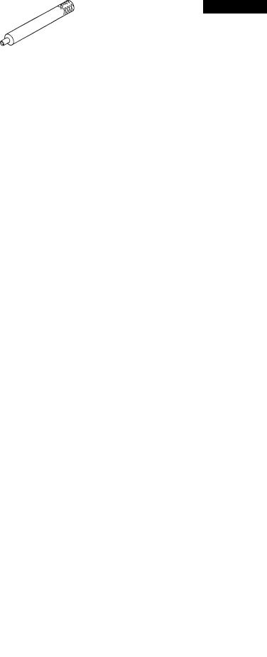
1 page 1
|
Models J08C-TP and J08C-TR |
ENGINE 3-2-1 |
SPECIAL TOOLS
Prior to starting an engine overhaul, it is necessary to have the following.
(1) Lifting parts
|
Shape |
Parts No. |
Parts name |
No./unit |
Application |
|
|
09491 — 1010 |
Wire cable |
1 |
Lifting engine |
||
|
SM3-J052 |
|||||
|
09433 — 1070 |
Eye bolt |
2 |
Lifting cylinder head |
||
|
SM3-J048 |
|||||
|
(2) Related parts of cylinder head |
|||||
|
Shape |
Parts No. |
Parts name |
No./unit |
Application |
|
|
09472 — 1210 |
Bar |
1 |
Caulking nozzle seat |
||
|
(Use together with 9800 — 06100) |
|||||
|
SM3-J050 |
|||||
|
9800-06100 |
(Steel ball) |
1 |
Caulking nozzle seat |
||
|
(Use together with 09472-1210) |
|||||
|
SM3-J054 |
|||||
|
09552-1090 |
Compression gauge |
1 |
Measuring compression |
||
|
adaptor |
(for size PF3/8) |
||||
|
SM3-J021 |
|||||

|
1 page 1 |
||||||
|
3-2-2 ENGINE |
Models J08C-TP and J08C-TR |
|||||
|
Shape |
Parts No. |
Parts name |
No./unit |
Application |
||
|
09552 — 1060 |
||||||
|
Press gauge adaptor |
1 |
Measuring compression |
||||
|
09552 — 1030 |
||||||
|
SM3-J022 |
||||||
|
09472 — 2100 |
Bar |
1 |
Strike-fitting valve stem seal |
|||
|
SM3-J055 |
||||||
|
09471 — 1520 |
Guide |
1 |
Strike-fitting valve guide |
|||
|
SM3-J051 |
||||||
|
09420 — 1100 |
Sliding hammer |
1 |
Removing main idle gear shaft |
|||
|
SM3-J131 |
||||||
|
09420 — 1442 |
Removing suband cam idle |
|||||
|
(Same as tool |
||||||
|
Sliding hammer |
1 |
gear shafts (Remove the |
||||
|
for pulling out |
||||||
|
adaptor from the top before use) |
||||||
|
injection nozzle) |
||||||
|
SM3-J132 |
||||||
|
(3) Related parts of valve |
||||||
|
Shape |
Parts No. |
Parts name |
No./unit |
Application |
||
|
09431 — 1020 |
Valve wrapping tool |
1 |
Valve wrapping |
|||
|
SM3-J053 |

|
1 page 1 |
||||||||||
|
Models J08C-TP and J08C-TR |
ENGINE 3-2-3 |
|||||||||
|
Shape |
Parts No. |
Parts name |
No./unit |
Application |
||||||
|
09470 — 1170 |
Valve spring press |
1 |
Removing and installing valve |
|||||||
|
spring |
||||||||||
|
SM3-J049 |
||||||||||
|
(4) Related parts of flywheel |
||||||||||
|
Shape |
Parts No. |
Parts name |
No./unit |
Application |
||||||
|
09481 — 1340 |
Guide |
1 |
Removing and installing |
|||||||
|
flywheel |
||||||||||
|
SM3-J116 |
||||||||||
|
(5) Related parts of cylinder block |
||||||||||
|
Shape |
Parts No. |
Parts name |
No./unit |
Application |
||||||
|
09407 — 1030 |
Oil seal press |
1 |
Press-fitting front oil seal |
|||||||
|
09407 — 1040 |
Oil seal press |
1 |
Press-fitting rear oil seal |
|||||||
|
SM3-J118 |
||||||||||
|
09420 — 1731 |
Oil seal puller |
1 |
Pulling out front oil seal |
|||||||
|
SM3-J115 |
||||||||||

|
1 page 1 |
|||||||
|
3-2-4 ENGINE |
Models J08C-TP and J08C-TR |
||||||
|
Shape |
Parts No. |
Parts name |
No./unit |
Application |
|||
|
09420 — 1742 |
Oil seal puller |
1 |
Pulling out rear oil seal |
||||
|
SM3-J117 |
|||||||
|
09420 — 1720 |
Cylinder liner puller |
1 |
Pulling out cylinder liner |
||||
|
SM3-J148 |
|||||||
|
09471 — 1490 |
Guide |
1 |
Insert guide for cylinder liner |
||||
|
SM3-J149 |
|||||||
|
09411 — 1300 |
Socket wrench |
1 |
Rear end plate TORX® bolt |
||||
|
SM3-J133 |
|||||||
|
09444 — 1630 |
Gauge |
1 |
Cooling jet check |
||||
|
SM3-J146 |
|||||||
|
9001 — 24262 |
Check bolt |
1 |
Cooling jet check |
||||
|
SM3-J151 |
|||||||
|
09472 — 1620 |
Tool |
1 |
Cooling jet check (Fixture for |
||||
|
correction) |
|||||||
|
SM3-J780 |
|||||||
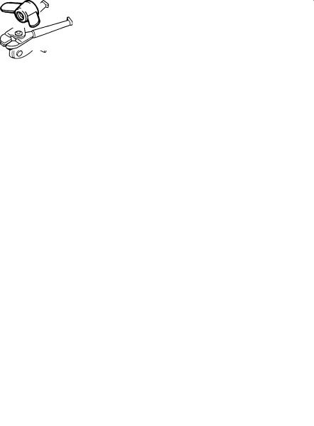
|
1 page 1 |
||||||
|
Models J08C-TP and J08C-TR |
ENGINE 3-2-5 |
|||||
|
(6) Related parts of piston |
||||||
|
Shape |
Parts No. |
Parts name |
No./unit |
Application |
||
|
09441 — 1320 |
Piston ring holder |
1 |
Used when inserting piston into |
|||
|
cylinder block |
||||||
|
SM3-J153 |
||||||
|
09442 — 1011 |
Piston ring expander |
1 |
Removing and installing piston |
|||
|
ring |
||||||
|
SM3-J145 |
||||||
|
09481-1130 |
Guide |
1 |
||||
|
SM3-J781 |
||||||
|
09402-1530 |
Press sub assembly |
1 |
For replacing the piston pin |
|||
|
bushing |
||||||
|
SM3-J782 |
||||||
|
9233-10360 |
Wing nut |
1 |
||||
|
SM3-J783 |
||||||

|
1 page 1 |
||||||
|
3-2-6 ENGINE |
Models J08C-TP and J08C-TR |
|||||
|
(7) Related parts of connecting rod |
||||||
|
Shape |
Parts No. |
Parts name |
No./unit |
Application |
||
|
09481 — 1540 |
Guide |
1 |
||||
|
SM3-J147 |
||||||
|
09402-1540 |
Press sub assembly |
1 |
Replacing connecting rod |
|||
|
bushing |
||||||
|
SM3-J152 |
||||||
|
9191 — 08252 |
Bolt |
1 |
||||
|
SM3-J150 |
||||||
|
(8) Related parts of filter |
||||||
|
Shape |
Parts No. |
Parts name |
No./unit |
Application |
||
|
09553 — 1021 |
Oil filter wrench |
1 |
Removing and installing oil filter |
|||
|
SM3-J784 |
||||||
|
09553 — 1010 |
Fuel filter wrench |
1 |
Removing and installing fuel filter |
|||
|
SM3-J785 |
||||||

|
1 page 1 |
||||||||
|
Models J08C-TP and J08C-TR |
ENGINE 3-2-7 |
|||||||
|
(9) Related parts of injection pump |
||||||||
|
Shape |
Parts No. |
Parts name |
No./unit |
Application |
||||
|
09511 — 2500 |
Wrench |
1 |
Injection pump coupling |
|||||
|
SM3-J200 |
||||||||
|
(10) Related parts for injection nozzle |
||||||||
|
Shape |
Parts No. |
Parts name |
No./unit |
Application |
||||
|
09420 — 1442 |
||||||||
|
(Same as the |
Sliding hammer |
1 |
Pulling out injection nozzle |
|||||
|
parts to remove |
(Use together with 09462 — 1130) |
|||||||
|
idler gear shaft) |
||||||||
|
SM3-J132 |
||||||||
|
09462 — 1130 |
Adaptor |
1 |
Pulling out injection nozzle |
|||||
|
(Use together with 09420 — 1442) |
||||||||
|
SM3-J172 |
||||||||
|
(11) Related parts of coolant pump |
||||||||
|
Shape |
Parts No. |
Parts name |
No./unit |
Application |
||||
|
09420 — 1820 |
Puller assembly |
1 |
Coolant pump vane |
|||||
|
SM3-J786 |
||||||||
|
09420 — 1810 |
Puller assembly |
1 |
Coolant pump pulley center |
|||||
|
SM3-J787 |
||||||||

|
1page 1 |
||||||
|
3-2-8 ENGINE |
Models J08C-TP and J08C-TR |
|||||
|
Shape |
Parts No. |
Parts name |
No./unit |
Application |
||
|
09444 — 1210 |
Belt tension gauge |
1 |
Adjusting V-belt tension |
|||
|
SM3-J788 |
||||||
|
(12) Related parts of air compressor |
||||||
|
Shape |
Parts No. |
Parts name |
No./unit |
Application |
||
|
09420 — 1670 |
Puller assembly |
1 |
Pulling out air compressor |
|||
|
sleeve |
||||||
|
SM3-J002 |
||||||
|
09482 — 2220 |
Press |
1 |
Strike-fitting air compressor |
|||
|
sleeve |
||||||
|
SM3-J003 |
||||||
|
09482 — 2230 |
Press |
1 |
Strike-fitting air compressor oil |
|||
|
seal |
||||||
|
SM3-J004 |
||||||
|
09420 — 1680 |
Puller assembly |
1 |
Pulling out air compressor gear |
|||
|
SM3-J005 |
||||||

1 page 1
|
Models J08C-TP and J08C-TR |
ENGINE 3-3-1 |
GENERAL
WARNING
The following items should be observed to prevent injury to yourself and others when servicing the engine or vehicle;
●Stop the engine and keep the engine off during checks and adjustments.
●Place the starter key in the “LOCK” position.
●Leave the engine stop knob pulled out fully. (For model equipped with manual engine stop control)
●Place the transmission shift lever in “NEUTRAL”.
●Apply the parking brake firmly.
●Block the wheels.
ENGINE OVERHAUL CRITERIA
FACTORS TO DETERMINE THE ENGINE OVERHAUL
1. LOW COMPRESSION PRESSURE
(1) Before measurement
1. Charge the battery completely.
2. Set the valve clearance to the correct value.
|
Intake : 0.30 mm (0.0118 in.) |
||
|
Exhaust : 0.45 mm (0.0177 in.) |
||
|
(when engine is cold) |
||
|
NOTE: Refer to page 3-18-4. |
||
|
3. |
Idle the engine (to 80 °C {176°F}). |
|
|
4. |
While the starter switch is at the LOCK position, dis- |
|
|
connect the engine stop motor. |
||
|
5. |
Remove all nozzle holders. |
|
|
SM3-J580 |
NOTE: |
Refer to page 3-6-3. |
|
Fig. 1 |
6. |
Remove the air cleaner hose. |

1 page 1
|
3-3-2 ENGINE |
Models J08C-TP and J08C-TR |
(2) Measurement
1.Insert the gauge adaptor into the nozzle holder hole.
Special tool: Compression gauge adaptor (09552 — 1090)
(09552 — 1060)
(09552 — 1030)
2.Run the engine with the starter and measure the compression pressure.
-J581
NOTE: Do not operate the starter for more than 15 sec-
Fig. 2
onds.
3. Measure the compression pressure of each cylinder.
NOTE: Do not allow gas leakage from the seal face.
Unit: kg/cm2 (lb/sq.in.)
|
Assembly standard |
Assembly limit |
Difference among |
Engine speed |
|
|
individual cylinders |
(rpm) |
|||
|
35 — 38 (498-540) |
28 (398) |
Less than 3 (43) |
180 — 220 |
|
(3) After measurement
1.Install the removed parts.
|
WARNING |
|||
|
Do not connect the electric harness with the en- |
|||
|
gine stop motor while the engine starter key is at |
|||
|
ON position as this may operate the engine stop |
|||
|
motor instantaneously and the link lever of the |
|||
|
SM3-J580 |
engine stop motor and the engine stop lever of the |
||
|
fuel injection pump will move, resulting in your |
|||
|
Fig. 3 |
|||
|
fingers caught by the lever. |
|||
1 page 1
|
Models J08C-TP and J08C-TR |
ENGINE 3-3-3 |
|
OIL |
||||||||||||||||
|
SM3-J024 |
||||||||||||||||
|
Fig. 4 |
||||||||||||||||
|
ATMOSPHERIC TEMPERATURE |
||||||||||||||||
|
S.A.E. |
||||||||||||||||
|
-10 |
0 |
32 |
50 |
70 |
90 |
100 |
˚F |
|||||||||
|
GRADE |
||||||||||||||||
|
-23 |
-18 |
0 |
10 |
21 |
32 |
39 |
˚C |
|||||||||
|
40 |
||||||||||||||||
|
30 |
||||||||||||||||
|
20W/20 |
||||||||||||||||
|
15W/40 |
||||||||||||||||
|
10W/30 |
||||||||||||||||
2.DECREASED OIL PRESSURE
Check the oil pressure warning lap when the oil and coolant temperature is hot [about 80°C (176°F)].
a.If the warning lamp is lit, check the oil level.
b.Check oil deterioration.
If oil quality is poor, replace with a suitable grade oil.
c.Remove the oil pressure switch and install the oil pressure gauge.
d.Measure the oil pressure at oil temperature 100°C (212°F).
Standard oil Pressure:
At 2,500 (rpm) 5.7 kg/cm2 (81.05 lb/sq.in.)
Service Limit:
At idle speed 0.5 kg/cm2 (7.11 lb/sq.in.)
Fig. 5
3. OTHER FACTORS
a. Blow-by gas increases.
b. Engine does not start easily. c. Engine output decreases.
d. Fuel consumption increases. e. Engine makes greater noise. f. Excessive oil consumption.

1 page 1
|
Models J08C-TP and J08C-TR |
ENGINE 3-4-1 |
SM3-J500
Fig. 1
SM3-J580
Fig. 2
Fig. 3
Fig. 4
DISMOUNTING THE ENGINE ASSEMBLY
1.BLOCK THE WHEELS OF THE VEHICLE.
1.Park the vehicle on level ground.
2.Block the wheels.
2.DISCONNECT THE ENGINE CONTROL AND THE STOP CABLE.
1.Set the starter switch to the ON position.
2.Disconnect the wires of the engine stop motor at the connector.
3.Set the starter switch to the LOCK position.
4.Tilt up the cab.
5.Disconnect the engine control and the stop cable at the injection pump.
3.DISCONNECT THE NEGATIVE TERMINAL OF THE BATTERY.
WARNING
Always disconnect the battery cable when servicing the engine.
4.DISCONNECT THE PARKING BRAKE CABLE (1).
1.Remove the center console.
2.Disconnect the parking brake cable at the lever.
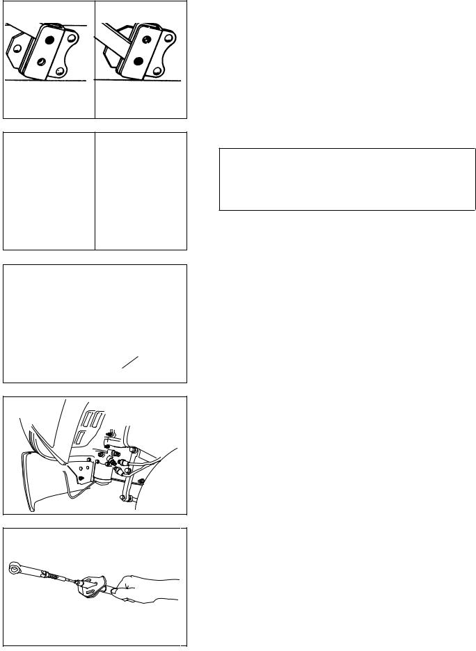
|
1 page 1 |
|||
|
3-4-2 ENGINE |
Models J08C-TP and J08C-TR |
||
|
OVER-TILTING |
NORMAL POSITION |
|
POSITION |
5.OVER-TILT THE CAB
NOTE: Refer to CAB in CHAPTER 19.
OPEN CLOSE
DRAINING PLUG
DRAINING PLUG
SM3-J705B
DRAINING PLUG
-J791
Fig. 9
Fig. 10
SM3-J589
Fig. 11
6.DRAIN THE COOLANT AND ENGINE OIL.
WARNING
To avoid the danger of burns do not drain the engine oil and coolant while the engine and radiator are still hot.
1.Drain the coolant from the radiator. (Fig. 7)
NOTE: The coolant can be drained more easily by removing the filler cap.
2. Drain the coolant from the cylinder block. (Fig. 
Coolant capacity: 21 L (22.19 US qt) 23 L (24.30 US qt)
(with transmission oil cooler only)
3. Drain the engine oil through the drain plug.
Engine oil capacity: 13.5 L (14.27 US qt)
7.DISCONNECT THE POWER STEERING LINES AT THE GEAR UNIT.
NOTE: Place a container under the gear unit.
8.DISCONNECT THE PARKING BRAKE CABLE (2).
1.Remove the bracket behind the cab, then pull out the parking brake cable.
NOTE: Pull out the cable straight and slowly. If pulled out forcefully, the gasket will crack. Cracked cables must be replaced with new ones.
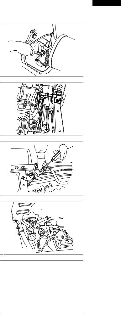
1 page 1
|
Models J08C-TP and J08C-TR |
ENGINE 3-4-3 |
SM3-J590
Fig. 12
SM3-J796
Fig. 13
Fig. 14
9.DISCONNECT THE SPEEDOMETER CABLE AT THE TRANSMISSION.
10.REMOVE THE TRANSMISSION CONTROL ROD TOGETHER WITH THE BRACKET AT THE TRANSMISSION.
11.REMOVE THE CLUTCH SLAVE CYLINDER.
1.Remove the connecting clip of the clutch hose.
2.Remove the return spring and the clevis of the lever.
3.Remove the slave cylinder together with the lines.
12.DISCONNECT THE POWER STEERING LINES AT THE PUMP.
NOTE: Be careful of oil leakage from the removed lines at the gear unit
13.DISCONNECT THE AIR HOSES WHICH CONNECT THE AIR CLEANER AND ENGINE.
14.REMOVE THE SPLASH BOARD.
15.REMOVE THE AIR CLEANER TOGETHER WITH THE BRACKET.
SM3-J595
Fig. 16
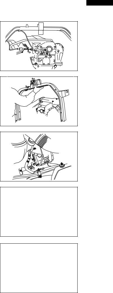
1 page 1
|
3-4-4 ENGINE |
Models J08C-TP and J08C-TR |
16.DISCONNECT THE ELECTRICAL WIRES (1).
1.Engine speed sensor
2.Glow plug
3.Rack sensor, pre-stroke actuator
4. Starter terminals B and C and grounding (frame end)
SM3-J596A
Fig. 17
Fig. 18
Fig. 19
SM3-J599
Fig. 20
17. REMOVE THE REAR CAB MOUNTING BRACKET.
18.DISCONNECT THE ELECTRICAL WIRES (2).
1.Water temperature sensor (2 parts)
2.Alternator
3.Magnetic clutch of the air conditioner
19.DISCONNECT THE HEATER HOSES.
20.DISCONNECT THE GAS LINES OF THE AIR CONDITIONER.
1.Use the refrigerant collector to discharge refrigerant.
2.Disconnect the gas lines of the air conditioner at the compressor.
21.DISCONNECT THE RADIATOR FROM THE FRAME.
1.Disconnect the reservoir hose.
2.Remove the radiator mounting.
SM3-J600A
Fig. 21

|
1 page 1 |
|
|
Models J08C-TP and J08C-TR |
ENGINE 3-4-5 |
Fig. 22
Fig. 23
SM3-J502
Fig. 24
22. REMOVE THE EXHAUST PIPE AND MUFFLER.
23.REMOVE THE PROPELLER SHAFT.
1.Remove the center bearing support.
NOTE: Attach a hoist to the propeller shaft.
2.Loosen the flange, then remove the propeller shaft.
24.REMOVE THE TRANSMISSION.
1.Place a jack under the bottom of the flywheel housing.
2.Place a transmission jack under the transmission.
WARNING
The engine must be suspended with a hoist until completion of disassembly of the transmission assembly.
3.Remove the mounting bolt of the mounting rubber behind the transmission.
4.Remove the mounting bolt of the transmission at the clutch housing, then remove the transmission.
NOTE: Jack up and align the transmission with the engine, then pull the transmission straight out.

|
1 page 1 |
|||||
|
3-4-6 ENGINE |
Models J08C-TP and J08C-TR |
||||
|
25. REMOVE THE ENGINE ASSEMBLY. |
|||||
|
1. |
Attach hoists to the engine hangers at the front and |
||||
|
rear ends of the engine, and lift slightly. |
|||||
|
2. |
Remove the engine mounting at the frame. |
||||
|
3. |
Remove the engine assembly together with the ra- |
||||
|
diator and inter cooler. |
|||||
|
4. |
Mount the engine assembly on a work stand. |
||||
|
SM3-J503 |
|||||
Fig. 25
26.REMOVE THE RADIATOR AND INTER COOLER.
1.Loosen the tightening band of the fan shroud.
2.Disconnect the radiator hoses and inter cooler hoses at the engine.
3.Remove the radiator and inter cooler.
NOTE: Attach a hoist to the radiator.
27. REMOVE THE CLUTCH COVER AND CLUTCH DISC. NOTE: Refer to CLUTCH in CHAPTER 5.
SM3-J746
Fig. 27
28.REMOVE THE AIR CONDITIONER COMPRESSOR.
1.Loosen the tension pulley, then remove the V-belt.
2.Remove the air conditioner compressor.

1 page 1
|
Models J08C-TP and J08C-TR |
ENGINE 3-5-1 |
REMOVAL OF THE ENGINE COMPONENT
PARTS
1.PREPARATION
1.Loosen the coolant drain cock of the oil cooler, then discharge coolant.
2.Loosen the oil drain plug of the oil filter, then discharge oil.
SM3-J606
Fig. 1
SM3-J504
Fig. 2
SM3-J607
Fig. 3
SM3-J608
Fig. 4
SM3-J609
Fig. 5
3.Clean the engine assembly.
a.Cover openings with tape.
b.Clean the engine assembly with a steam cleaner.
NOTE: Do not apply steam directly to the electrical components. (Alternator, starter, etc.)
4.Mount the engine assembly on a work stand.
2.REMOVE THE POWER STEERING OIL PUMP.
3.REMOVE THE STARTER.
1.Put alignment marks on the harness and the starter terminal, then remove the harness.
2.Remove the starter from the engine.
4.REMOVE THE FUEL FILTER AND FUEL LINES.
Remove the fuel lines, oil lines and fuel leakage lines.
NOTE:
●Cover openings to prevent foreign matter from entering.
●Refer to page 3-12-1.

|
1 page 1 |
||||
|
3-5-2 ENGINE |
Models J08C-TP and J08C-TR |
|||
|
5. REMOVE THE INTAKE MANIFOLD. |
||||
SM3-J613
Fig. 6
Fig. 7
Fig. 8
SM3-J612
Fig. 9
SM3-J614
6.REMOVE THE INJECTION PUMP.
1. Remove the through bolt of the coupling.
2.Use the following special tool and loosen the adjusting bolt.
Special tool: Injection pump coupling wrench (09511 — 2500)
3.Remove the mounting bolt of the injection pump, then remove the pump assembly.
NOTE: Cover openings to prevent foreign matter from entering.
7.REMOVE THE AIR COMPRESSOR.
1.Remove the oil lines, refrigerant lines and air lines.
2.Remove the air compressor.
3.Remove the mounting bolt of the air compressor, then remove the air compressor.
NOTE: Do not remove the air compressor forcefully. The spigot may be damaged, or oil leakage may occur due to removal of liquid gasket between the flywheel housing and the rear end plate.
Fig. 10

|
1 page 1 |
|
|
Models J08C-TP and J08C-TR |
ENGINE 3-5-3 |
8.REMOVE THE TURBOCHARGER.
NOTE: Refer to TURBOCHARGER in CHAPTER 51.
SM3-J615
Fig. 11
9.REMOVE THE OIL FILTER AND OIL COOLER.
1.Remove the oil lines.
2.Remove the oil filter.
Special tool: Oil filter wrench (09553 — 1021)
3. Remove the oil cooler.
10.REMOVE THE EXHAUST MANIFOLD.
11.REMOVE THE V-BELT AND THE ALTERNATOR.
1.Loosen the V-belt adjustment bolt.
2.Loosen the through bolt.
3.Remove the V-belt, then remove the alternator.
SM3-J619A
Fig. 14
12.REMOVE THE FAN CLUTCH TOGETHER WITH THE COOLING FAN.
SM3-J620
Fig. 15

|
1 page 1 |
||||
|
3-5-4 ENGINE |
Models J08C-TP and J08C-TR |
|||
|
13. REMOVE THE THERMOSTAT CASE. |
||||
SM3-J621
Fig. 16
14. REMOVE THE COOLANT PUMP.
SM3-J622
Fig. 17

1 page 1
|
Models J08C-TP and J08C-TR |
ENGINE 3-6-1 |
CAMSHAFT HOUSING AND CYLINDER HEAD
1
2
3
4
5
6
13
12
16
17
21
22
23
24
25
26
27
30
31
32
33
7
11
15
14
28
29
18
20
18 19
SM3-J264A
Fig. 1

1 page 1
|
3-6-2 ENGINE |
Models J08C-TP and J08C-TR |
35
34
|
1. |
Oil filler cap |
||
|
2. |
Cylinder head cover |
20. |
Idler gear shaft |
|
3. |
Silent block |
21. |
Cross head |
|
4. |
Spacer |
22. |
Valve spring retainer |
|
5. |
Head cover gasket |
23. |
Valve spring seat upper |
|
6. |
Valve rocker shaft |
24. |
Valve spring outer |
|
7. |
Lock nut |
25. |
Valve spring inner |
|
8. |
Valve rocker arm |
26. |
Valve stem seal |
|
9. |
Adjusting screw |
27. |
Valve spring seat lower |
|
10. |
Nozzle clamp |
28. |
Cross head adjusting screw |
|
11. |
Valve rocker support |
29. |
Lock nut |
|
12. |
Camshaft bearing |
30. |
Cylinder head |
|
13. |
Camshaft bearing cap |
31. |
Cylinder head gasket |
|
14. |
Camshaft |
32. |
Valve seat |
|
15. |
Camshaft drive gear |
33. |
Valve |
|
16. |
Camshaft housing |
34. |
Valve stem guide |
|
17. |
Camshaft housing gasket |
35. |
Nozzle seat |
18.Idler gear thrust plate
19.Camshaft idler gear
SM3-J265
Fig. 2

1 page 1
|
Models J08C-TP and J08C-TR |
ENGINE 3-6-3 |
DISMOUNTING
1.REMOVE THE CYLINDER HEAD COVER.
NOTE: Clean all dust from around the cylinder head cover before removing it to prevent foreign particles from getting in.
SM3-J623
Fig. 3
NOZZLE CLAMP BOLT
LEAKAGE PIPE
CAM HOUSING
O-RING
NOZZLE HOLDER
ASSEMBLY
SM3-J178
Fig. 4
SM3-J624
Fig. 5
2.REMOVE THE INJECTION NOZZLE.
1.Remove the leakage pipe.
2.Loosen the injection pipe nut.
3.Remove the injection pipe seal mounting bolts. Remove the injection pipe seal together with the injection pipe out of the cam housing.
4.Remove the nozzle clamp bolt.
5.Pull out the nozzle holder assembly, avoiding any interference.
NOTE: If difficult, use a special tool, sliding hammer (09420 — 1442), for easier removal.
6.Remove the O-ring.
NOTE: Replace the O-ring with a new one.

1 page 1
|
3-6-4 ENGINE |
Models J08C-TP and J08C-TR |
LOCK NUT
ADJUSTING
SCREW
SM3-J056
Fig. 6
3.LOOSEN THE VALVE CLEARANCE ADJUSTING SCREW.
1.Loosen the lock nut at the top of the rocker arm, then wind up the adjusting screw completely.
NOTE: If the adjusting screw is left unwound, the rocker shaft may bend when the rocker arm support is loosened.
|
4. REMOVE THE ROCKER ARM ASSEMBLY. |
|||||||
|
1. Remove the rocker arm support bolt in the order as |
|||||||
|
ROCKER ARM SUPPORT |
shown in the figure. |
||||||
|
NOTE: When the rocker arm assembly is removed, the |
|||||||
|
rocker arm and rocker arm support tend to come |
|||||||
|
7 |
5 |
3 |
1 |
2 |
4 |
6 |
off the rocker shaft. Be careful in handling. |
SM3-J266
Fig. 7
5.REMOVE THE CAMSHAFT.
1.Remove the cam bearing cap bolt.
2.Remove the camshaft together with the gear.
NOTE: Be extremely careful not to drop any part into the interior of the engine.
SM3-J625
Fig. 8
6.REMOVE THE CAM HOUSING.
1.Remove the cam housing bolts.
2.Tap and remove the cam housing with a plastic hammer.
SM3-J626
Fig. 9
7. REMOVE THE CYLINDER HEAD BOLTS.
Remove the cylinder head bolts in the order as shown in the figure.
SM3-J276B
Fig. 10

|
1 page 1 |
|||||
|
Models J08C-TP and J08C-TR |
ENGINE 3-6-5 |
||||
|
8. |
LIFT AND REMOVE THE CYLINDER HEAD FROM THE |
||||
|
CYLINDER BLOCK. |
|||||
|
Special tool: Eye bolt (09433 — 1070) |
|||||
|
NOTE: |
|||||
|
● Place a piece of wood between the cylinder head and |
|||||
|
table. |
|||||
|
● When removing the cylinder head together with the |
|||||
|
injection nozzle, avoid contact between the injection |
|||||
|
SM3-J627 |
nozzle and a piece of wood. |
|
Fig. 11 |
● Check that there is no oil, water or gas leakage in the |
|
cylinder head gasket if overheated or not. |

1 page 1
|
3-6-6 ENGINE |
Models J08C-TP and J08C-TR |
DISASSEMBLING
REMOVE THE CAM IDLER GEAR.
1.Remove the cam idler gear.
SM3-J628
Fig. 12
2. Using the special tool, remove the cam idler gear.
Special tool: Sliding hammer (09420 — 1830)
SM3-J629
Fig. 13
DISASSEMBLE THE VALVE SYSTEM.
1.Using the special tool, press fit the valve spring seat upper, then remove the valve spring retainer.
Special tool: Valve spring press (09470 — 1170)
SM3-J060
Fig. 14
2.Remove the valve spring seat upper, valve spring outer and inner.
3.Remove the intake and exhaust valves from the cylinder head.
NOTE:
●Do not remove the valve guide and valve spring seat lower unless they need to be replaced.
●Align the removed parts in the order of the cylinder
SM3-J061A No.

1 page 1
|
Models J08C-TP and J08C-TR |
ENGINE 3-6-7 |
SM3-J062
Fig. 16
|
SM3-J103 |
||||
|
Fig. 17 |
||||
|
SM3-J630 |
||||
|
Fig. 18 |
||||
|
B |
E’ |
F’ |
G’ |
A’ |
|
C |
C’ |
|||
|
D |
D’ |
|||
|
A |
E |
F |
G |
B’ |
|
SM3-J505 |
||||
|
Fig. 19 |
||||
|
SM3-J506 |
||||
INSPECTION AND REPAIR
CYLINDER HEAD
NOTE:
●Clean the cylinder head thoroughly with a commercial cleaning agent before inspection.
●Do not damage the lower surface of the cylinder head.
INSPECT THE CYLINDER HEAD FOR CRACKS.
Check the head surface and intake and exhaust valve seats, for cracks, using a dye penetrant. If cracks are found, replace the cylinder head.
CHECK THE CYLINDER HEAD FLATNESS.
1.Check the cylinder head surface for flatness with a straight edge and a thickness gauge. If the measurements exceed service limits, replace the cylinder head.
Standard: 0.06 mm (0.0024 in.) or less for longitudinal direction
0.03 mm (0.0012 in.) or less for lateral direction
Service limit: 0.20 mm (0.0079 in.)
2.Check the flatness of the intake and exhaust manifolds mounting surfaces.
Standard: 0.06 mm (0.0024 in.) or less for longitudinal direction
0.03 mm (0.0012 in.) or less for lateral direction
Service limit: 0.20 mm (0.0079 in.)
Fig. 20

1 page 1
|
3-6-8 ENGINE |
Models J08C-TP and J08C-TR |
INSPECT THE VALVE CONTACT SURFACES FOR PROPER
CONTACT.
1.Visually check valves for damage, burn marks, carbon accumulation, warpage, or cracks in valve heads, valve stems, and valve stem grooves. Replace valves which are excessively worn, burnt, warped or cracked.
SM3-J631
Fig. 21
2.Check the valve seating condition.
Lightly apply red lead marking compound to the valve face. Install the valve with a special tool, tap and rotate the valve against the seat. Check the valve face and valve seat for seating. When the red lead mark is not concentric or even all around the valve face or seat, correct the valve face or the valve seat.
Special tool: Valve lapping tool (09431 — 1020)
SM3-J104
Fig. 22
HAND-LAP THE VALVE AND VALVE SEAT.
Lightly apply lapping compound to the valve face. Install the valve with a special tool, tap and rotate the valve against the seat.
NOTE:
●Following completion of hand-lapping, clean off any lapping compound which has adhered to the valves and valve seats.
●Following hand-lapping, always recheck the seating condition.
Special tool: Valve lapping tool (09431 — 1020)
GRIND VALVES
NOTE:
●Grinding of valves should only be performed when hand-lapping does not result in proper seating.
●Following hand-lapping, always recheck the seating condition.
WARNING
When grinding, a metal tip may fly off on impact. Wear safety glasses to protect your eyes.

|
1page 1 |
|
|
Models J08C-TP and J08C-TR |
ENGINE 3-6-9 |
|
30˚ |
|||||||
|
45˚ |
|||||||
|
INTAKE |
EXHAUST |
||||||
|
SM3-J097 |
|||||||
|
Fig. 25 |
|||||||
|
HAMMER |
BLOCK BRASS |
||||||
|
VALVE SEAT |
|||||||
|
VALVE |
ELECTRIC WELDING |
||||||
|
APPLIED |
|||||||
|
GRIND THIS POINT |
|||||||
|
WITH A GRINDER |
|||||||
|
SM3-J064 |
|||||||
|
Fig. 26 |
|||||||
|
C |
C |
||||||
|
INTAKE |
EXHAUST |
||||||
|
SM3-J065 |
|||||||
|
Fig. 27 |
Assembly standard:
Valve seat (Intake): 30°00′ — 30°35′ Valve face (Intake): 29°30′ — 30°00′ Valve seat (Exhaust): 45°00′ — 45°30′ Valve face (Exhaust): 44°30′ — 45°00′
IF NECESSARY, REPLACE THE VALVE SEAT.
1.Cut three places on the circumference of an unwanted valve and weld it to the valve seat.
NOTE: To protect the lower surface of the cylinder head from welding spatter, be sure to apply grease before welding.
2.Place a back plate at the top of the valve stem and strike it with a hammer to remove the valve seat.
NOTE: When striking, a metal tip may fly off on impact. Wear safety glasses to protect your eyes.
3.Machine the valve seat according to the specified valve seat dimensions.
Dimensions of the valve seat machining:
|
Intake |
Exhaust |
||||
|
Unit:mm |
Unit:in. |
Unit:mm |
Unit:in. |
||
|
Clynder |
A |
41-41.016 |
1.6142-1.6148 |
39-39.016 |
1.5355-1.5360 |
|
head side |
|||||
|
B |
9.4-9.6 |
0.3701-0.3779 |
8.6-8.8 |
0.3386-0.3464 |
|
|
Valve seat |
C |
41.085-41.1 |
1.6176-1.6181 |
39.12-39.135 |
1.5402-1.5407 |
|
side |
D |
7-7.2 |
0.2756-0.2834 |
6-6.2 |
0.2363-0.2440 |
4.Heat the cylinder head to approx. 80°C (176°F) — 90°C (194°F) with hot water. Cool the valve seat with dry ice for approx. 30 minutes. Hold the seat with pincers and place it into the heated cylinder head. The valve seat can be easily made to fit by lightly hitting it.
WARNING
SM3-J066 ● Never touch the cooled valve seat with your bear
hands.
Fig. 28
●When striking, a metal tip may fly off on impact. Wear safety glasses to protect your eyes.
●Following valve grinding, always recheck the seating condition.

|
1 page 1 |
|||
|
3-6-10 ENGINE |
Models J08C-TP and J08C-TR |
||
VALVE SEAT
VALVE
SINK
DIMENSION CYLINDER VALVE
HEAD
SM3-J508
Fig. 29
SM3-J509
Fig. 30
MEASURE THE VALVE SINK. Assembly standard:
Intake: 0.55 — 0.85 mm (0.0217 — 0.0334 in.) Exhaust: 1.05 — 1.35 mm (0.0414 — 0.0531 in.)
Repair limit:
Intake: 1.1 mm (0.0433 in.) Exhaust: 1.6 mm (0.0630 in.)
NOTE:
●If the valve heads are protruding from cylinder head surface, the valve heads may hit against the pistons while the engine is running.
●Following replacement of valve and valve seat, always recheck the seating condition.
MEASURE THE CLEARANCE BETWEEN THE VALVE STEM AND VALVE GUIDE.
1.Measure the outside diameter of the valve stem with a micrometer. If the value exceeds the service limit, replace the valve.
Nominal dimension: 7.0 mm (0.2756 in.) Service limit: Intake 6.92 mm (0.2724 in.)
Exhaust 6.84 mm (0.2693 in.)
90°
SM3-J510
Fig. 31
SM3-J511
Fig. 32
2.Calculate the clearance between the valve stem and valve guide. If the clearance exceeds the service limit, replace the valve or valve guide.
Nominal dimension:
Intake: 0.023 — 0.058 mm (0.0010 — 0.0022 in.) Exhaust: 0.037 — 0.067 mm (0.0015 — 0.0026 in.)
Service limit:
Intake: 0.10 mm (0.0039 in.) Exhaust: 0.12 mm (0.0047 in.)
IF NECESSARY, REPLACE THE VALVE GUIDE.
1.Remove the valve stem seal.
2.Strike the valve guide out with a brass bar and a hammer.
WARNING
When striking, a metal tip may fly off on impact. Wear safety glasses to protect your eyes.

|
1 page 1 |
|||||
|
Models J08C-TP and J08C-TR |
ENGINE 3-6-11 |
||||
|
3. Press fit a new valve guide straight allowing it to pro- |
|||||
|
INTAKE |
|||||
|
EXHAUST |
|||||
|
trude as shown in the figure. |
|||||
|
NOTE: Apply engine oil lightly to the valve guide outer |
|||||
|
circumference before installation. |
SM3-J065
Fig. 33
|
VALVE STEM SEAL |
|
|
VALVE SPRING SEAT |
SPECIAL |
|
LOWER |
TOOL |
VALVE
SM3-J068
Fig. 34
IF NECESSARY, REPLACE THE VALVE STEM SEAL.
Replace the valve stem seal when the valve guide is replaced or when seal clearance is excessive or the stem seal has been worn or damaged.
First, install the lower spring seat and valve to the cylinder head (for guide of special tool), then apply engine oil to the lip of the stem seal and drive the guide with a special tool.
Special tool: Valve stem seal press (09472 — 2100)
COAT OIL
B
A
SM3-J068
Fig. 35
WARNING
When striking, a metal tip may fly off on impact. Wear safety glasses to protect your eyes.
NOTE:
●After installing the valve stem seal, make sure there is a gap (A) and (B) as shown in the figure.
●Do not use the special tool if its surface contacting the valve spring lower seat is deformed.
INSPECT THE VALVE SPRINGS.
1.Check the valve springs for squareness using a square and a thickness gauge. If a spring is out of square beyond the service limit, replace it.
Limit: 2.0 mm (0.078 in.) or more

1 page 1
|
3-6-12 ENGINE |
Models J08C-TP and J08C-TR |
2.Measure the valve spring tension at a specified length with the valve spring tester. If the spring force is lower than the service limit, replace it.
SM3-J098
Fig. 37
|
Free length mm (in.) |
Setting height |
Setting load kg (lb) |
|||||
|
Nominal dimension |
Service limit |
mm (in.) |
Nominal dimension |
Service limit |
|||
|
Outer spring |
Intake |
75.7 (2.980) |
75.4 (2.968) |
46.8 (1.843) |
46.4 (102.23) |
— |
|
|
Exhaust |
75.7 (2.980) |
75.4 (2.968) |
46.8 (1.843) |
44.2 (97.44) |
— |
||
|
Inner spring |
Intake |
64.6 (2.543) |
64.3 (2.531) |
44.8 (1.764) |
21.7 (47.85) |
— |
|
|
Exhaust |
64.6 (2.543) |
64.3 (2.531) |
44.8 (1.764) |
20.4 (44.98) |
— |
||
3.Visually check the contact surface of the upper and lower valve spring seats. Replacement is necessary if damage such as wear and scratches is excessive.
SM3-J099
Fig. 38
INSPECT THE CYLINDER HEAD COOLANT GALLERY FOR LEAKS.
Close all coolant holes and apply air pressure of about 2.5 kg/cm2 (36 lb/sq. in.) from one of the coolant holes. Immerse the cylinder head into the water, then check for air leakage. If any leakage is found, replace the cylinder head.
|
IF NECESSARY, REPLACE THE NOZZLE SLEEVE. |
|||
|
1. Engage a tap to the nozzle sleeve from the bottom |
|||
|
of the cylinder head. Screw in an appropriate bolt, |
|||
|
then strike the bolt head with a hammer and drive |
|||
|
out the nozzle sleeve. |
|||
|
WARNING |
|||
|
When striking, a metal tip may fly off on impact. |
|||
|
SM3-J069 |
SM3-J070 |
Wear safety glasses to protect your eyes. |
|
Fig. 39

1 page 1
|
Models J08C-TP and J08C-TR |
ENGINE 3-6-13 |
CYLINDER HEAD
O-RING
NOZZLE SLEEVE
SM3-J071
Fig. 40
2.Install an O-ring to the nozzle sleeve insert hole of the cylinder head. Then apply liquid gasket (Three Bond No. 1211 or equivalent) to the bottom of a new nozzle sleeve, and insert it to the nozzle sleeve insert hole of the cylinder head.
NOTE: Be sure to install a new O-ring. Reused O-rings may cause water or gas leakage and lead to overheating or cracked heads.
|
SPECIAL |
NOZZLE |
|
|
TOOL |
SLEEVE |
CYLINDER
HEAD
SPECIAL
TOOL
SM3-J072
Fig. 41
CYLINDER HEAD
SM3-J100
Fig. 42
SM3-J142
Fig. 43
SM3-J634
Fig. 44
3. Caulk the nozzle sleeve with the special tool.
Special tool: Sleeve bar (09472 — 1210) Steel ball (9800 — 06100)
4.Install the injection nozzle to the cylinder head. Then measure the protrusion of the injection nozzle from the lower surface of the cylinder head with a vernier caliper. If the value exceeds the service limit, replace the injection nozzle.
NOTE: Refer to page 3-12-5.
Assembly standard: 2.25 — 2.75 mm (0.0886 — 0.1082 in.) Service limit: 2.75 mm (0.1082 in.)
MEASURE THE CLEARANCE BETWEEN THE CAM IDLER GEAR SHAFT AND CAM IDLER GEAR BUSHING.
1.Measure the outside diameter of the cam idler gear shaft with a micrometer. If the value exceeds the service limit, replace the cam idler gear shaft.
Assembly standard: 34.0 mm (1.3386 in.)
Service limit: 33.95 mm (1.3366 in.)
2.Measure the inside diameter of the cam idler gear bushing with a cylinder gauge. If the value exceeds the service limit, replace the cam idler gear.
Assembly standard: 34.0 mm (1.339 in.)
Service limit: 34.025 mm (1.340 in.)
3.Calculate the clearance between the idler gear shaft and idler gear bushing. If the value exceeds the service limit, replace the idler gear shaft and/or idler gear bushing.
Assembly standard: 0.025 — 0.075 mm (0.0010-0.0029 in.) Service limit: 0.20 mm (0.0079 in.)

|
1 page 1 |
|||
|
3-6-14 ENGINE |
Models J08C-TP and J08C-TR |
||
INSPECT THE INTAKE AND EXHAUST MANIFOLDS. NOTE: Clean the intake and exhaust manifolds with a
commercial cleaning agent before inspection.
1.Check the intake and exhaust manifolds for cracks, using a dye penetrant. If cracks are found, replace the manifold.
SM3-J635
Fig. 45
SM3-J517
Fig. 46
SM3-J570
Fig. 47
2.Measure the intake manifold flatness with a straight edge and a thickness gauge. If the value exceeds the service limit, replace the intake manifold.
Service limit: 0.2 mm (0.0079 in.)
3.Measure the exhaust manifold flatness with a straight edge and a thickness gauge. If the value exceeds the service limit, correct the exhaust manifold by grinding it to become within 0.14 mm (0.006 in.) per 2 flanges or 0.1 mm (0.004 in.) per flange.
Service limit: 0.2 mm (0.0079 in.)
4.Visually check the seal ring of the exhaust manifold for deformation or wear. Replacement is necessary if damage such as deformation and wear is excessive.
INSPECT THE CAMSHAFT.
1.Visually check the camshaft surface for wear and scratches.


![[IMG]](http://piratebooks.ru/attachments/dvigateli-hino-j05c.jpg)