-
Page 1
EWN-R (Standard) Instruction manual Thank you for choosing our product. Please read through this instruction manual before use. This instruction manual describes important precautions and instructions for the product. Always keep it on hand for quick reference. 2008 IWAKI CO., LTD. -
Page 2: Order Confirmation
Order confirmation After unpacking, check the following points. Contact us or your nearest distributor if the delivery is imperfect. a. Check if the delivery is as per order. Check the nameplate to see if the in- formation such as discharge capacity, discharge pressure and power voltage are as per order.
-
Page 3: Table Of Contents
Contents Order confirmation ………………… 2 Safety instructions …………… 6 Warning ………………….7 Caution ………………….8 Precautions for use ………………10 Overview ………………12 Introduction …………………12 Pump structure & Operating principle …………12 Features …………………..14 Operational functions……………….14 Part names…………………..19 Pump………………….19 Operational panel ………………20 Basic displays &…
-
Page 4
Operation ………………37 Before operation …………………37 Points to be checked ……………….37 Retightening of pump head fixing bolts …………37 Use of hexagon wrench instead of a torque wrench ……38 Degassing ………………..38 Flow rate adjustment ……………….41 Stroke rate adjustment …………….42 Stroke length adjustment…………… -
Page 5
Maintenance …………….76 Troubleshooting ………………… 77 Inspection ………………….. 79 Daily inspection ……………….79 Periodic inspection ………………79 Wear part replacement ……………… 80 Wear part list ………………..80 Before replacement ………………81 Valve set replacement ……………..81 Discharge valve set dismantlement/assembly ……..81 Suction valve set dismantlement/assembly ………. 83 Spacer set replacement (Auto degassing type) …….. -
Page 6: Safety Instructions
Safety instructions Read through this section before use. This section describes important information for you to prevent personal injury or property damage. ■ Symbols In this instruction manual, the degree of risk caused by incorrect use is noted with the following symbols. Please pay attention to the information associated with the symbols.
-
Page 7: Warning
WARNING Turn off power before work Risk of electrical shock. Be sure to turn off power to stop the pump and related devices before work. Electrical shock Stop operation On sensing any abnormality or danger, suspend operation immedi- ately and inspect/solve problems. Requirement Do not use the pump in anything other than a specified purpose The use of the pump in any purpose other than those clearly speci-…
-
Page 8: Caution
CAUTION A qualified operator only The pump must be handled or operated by a qualified person with a full understanding of the pump. Any person who is not familiar with Requirement this product should not take part in operation or management. Use a specified power only Do not apply any power other than the one specified on the nameplate.
-
Page 9
Do not use the pump in a water place The pump is not totally waterproof. The use of the pump in water or high humidity could lead to electrical shock or short circuit. Prohibition Earthing Risk of electrical shock. Always earth the pump. Earthing Install an earth leakage breaker An electrical failure of the pump may adversely affect related de-… -
Page 10: Precautions For Use
Precautions for use • Electrical work should be performed by a qualified opera- tor. Otherwise, personal or property damage accident may result. Caution • Do not install the pump in the following places where… –Under a flammable atmosphere or in a dusty/humid place. –Under direct sunlight or wind &…
-
Page 11
• Be careful not to drop the pump onto the floor. A strong impact may reduce pump performance. Do not use a pump which has once damaged. Otherwise an electrical leak or shock may result. • The pump is a light water-/dust-proof structure of IP65, but is not totally waterproof. -
Page 12: Overview
Overview The information such as characteristics, features and part names are described in this section. Introduction Pump structure & Operating principle The EWN series is a diaphragm metering pump which consists of a pump head, drive unit and control unit. A diaphragm is directly driven by electromag- netic force.
-
Page 13
● Auto degassing system Discharge port Air vent port Automatic air vent valve body LOCK Air vent valve Pump head valve Pump head Suction port • Once air is entrained through the suction port, the working pressure difference between the pump head valve and the air vent valve separates entrained air from liquid. -
Page 14: Features
Features ● Multivoltage operation The EWN-R series is a multivoltage type (100-240VAC) and can be selected without concern for local power voltage. ● High turndown ratio Digitally-controlled stroke rate range is 0.1-100%. The stroke length shifts for a fine flow adjustment. ●…
-
Page 15
Multiplier programming (See page 51) 1-9999 shots can be programmed to one pulse signal. *In the EXT operation, the pump runs at the manual operation stroke rate. *The pump makes one shot per pulse when the multiplier is programmed to 1. Example) When the multiplier is programmed to 5, the pump makes five shots per signal. -
Page 16
ANA. R (analogue rigid) programming (See page 57) The pump increases/decreases a flow rate in proportion to 0-20mA. Four (4- 20, 20-4, 0-20, 20-0) programs are provided. In «4-20» or «20-4» program a disconnection sensor works to stop the pump as a current value falls below 4mA («DISCN»… -
Page 17
● STOP function (See page 60) The start/stop of the pump can be controlled by the external signal. When «NOR. OP» is selected… The pump stops while receiving the external signal via the STOP terminal. *The pump resumes operation when the STOP signal is released. STOP signal input Pump operation Stop… -
Page 18
● AUX function (See page 40) The pump runs at the maximum stroke rate while receiving the external sig- nal via the AUX terminal. Use this function for degassing. Pulse signal input Pump operation 1 2 3 4 5 1 2 3 ●… -
Page 19: Part Names
Part names Pump Adjusting screw Used for opening the air vent port. Control unit Used for the start/stop of the Air vent port pump and stroke rate adjust- Always connect a tube. ment/programming. Be sure to return the tube end to a supply tank or a container.
-
Page 20: Operational Panel
Operational panel Display An operational status, a selected mode and a programmed value are shown here. START/STOP key Used for starting/stopping UP key the pump operation. Used for increasing numeric val- ues or selecting a programming mode. EXT key Used for entering the EXT mode.
-
Page 21: Basic Displays & Pump States
■ Basic displays & Pump states STOP LED ON LED lights ON LED lights ON LED blinks lights red orange green green Manual wait The pump state. Display is running in ― shows stroke ― manual mode. rate in %. Display shows stroke rate in %.
-
Page 22
STOP LED ON LED lights ON LED lights ON LED blinks lights red orange green green EXT(Multiply) programming mode. The MULT pump is set ― ― ― to make the displayed # of shots per signal. EXT(Divide) programming mode. The pump is set ―… -
Page 23: Identification Codes
Identification codes The model codes of the pump/drive units and the control unit represent the fol- lowing information. Pump/Drive units EWN — B 11 VC f g h a. Series name EWN: Multivoltage electromagnetic metering pump b. Drive unit (Average power consumption) B: 20W C: 24W c.
-
Page 24
e. Tube connection bore Hose size (ID×OD) Wet end materials Pump model VC/VH/PC/PH/TC/VC-C/VH-C/ ø4×ø6*² EWN-09/-11/-16 & -21 VC-A/VH-A VC/VH/PC/PH/TC/VC-C/VH-C/ ø6×ø8*² EWN-09/-11/-16 & -21 VC-A/VH-A ø9×ø12 VC/VH/PC/PH EWN-31 & -36 ø10×ø12 EWN-31 & -36 ø6×ø12 VC-C/VH-C EWN-09/-11/-16 & -21 code*¹ Rc 1/4 FC/SH/SH-H/SH-H2 EWN-11/-16/-21/-31 &… -
Page 25: Installation
Installation This section describes the installation of the pump, tubing and wiring. Read through this section before work. Observe the following points when installing the pump. • Be sure to turn off power to stop the pump and related devices before work. •…
-
Page 26: Pipework
Pipework Connect tubes to the pump and install a check valve. Tube end (Side view) Before operation • Cut the tube ends flat. Necessary tools • Adjustable wrench or spanner Tube connection a. Pass a tube into the fitting nut and Tube hose stopper and then slide it down to Fitting nut…
-
Page 27
Connect an air bleed tube into the Air vent port air vent port. Route back the other tube end to a supply tank or a container. For the auto degassing type, con- Tube nect another air bleed tube into the automatic air vent valve body as well. -
Page 28: Check Valve Mounting
Check valve mounting Install an optional check valve to the EWN (or a back pressure valve to the FC type) for the prevention of a back flow, siphon and overfeeding. In the following cases be sure to install the check valve. •…
-
Page 29
Mount a check valve at the discharge tube end. * The CAN/CBN check valve and the BVC back pressure valve have R1/2 and R3/8 thread connections as well as a tube connection. Cut off and adjust the connection length to fit the check valves into tubing. CAN check valve BVC back pressure valve R1/2… -
Page 30: Wiring
Wiring Wiring for a power voltage and an external signal. Observe the following points during wiring work. • Electrical work should be performed by a qualified operator. Always ob- serve applicable codes or regulations. • Observe the rated voltage range, or the electrical circuit in the control unit may fail.
-
Page 31
NOTE • Do not share a power source with a high power device which may generate surge voltage. Otherwise an electronic circuit may fail. The noise caused by an inverter also affects the circuit. • Energize the pump with a power voltage via a mechanical relay or switch. Do not fluctuate the voltage, or CPU may malfunction. -
Page 32: Signal Wire Connection
Precautions for ON-OFF control by a mechanical relay The control unit is equipped with CPU. Always start/stop the pump by the STOP signal for ON-OFF control. Try not to turn on and off the main power. Otherwise, observe the following points. •…
-
Page 33
NOTE • Do not lay on these signal cables in parallel with a power cable or combine them in a concentric cable (ex. 5 wires cable). Otherwise noise is generated through the cables due to induction effect and it results in malfunction or failure. •… -
Page 34: Connections
■ Connections • Level sensor The EWN have two stage level sensor, the Pre-STOP and STOP alarms. Con- nect the pre-alarm signal to the Pre-STOP and the alarm signal to the STOP. The pre-alarm functions just to notify a low liquid level by flashing the LED orange while the pump is running.
-
Page 35
• Pulse signal In the EXT (MULT or DIV) mode, the pump runs along with a multiplier or a divisor as receiving the pulse signal. • When using an open collector… Pay attention to polarity. Pulse is plus(+), and COM1 is minus(-). (Maximum 2.3mA at 12V) •… -
Page 36
• OUTPUT signal The pump sends out the OUTPUT signal along with injections or the STOP signal along with the external STOP signal input via a Photo MOS relay. *The maximum applied voltage is 24VAC/DC. 1 : Free 2 : Free 3 : Free 4 : OUT 5 : COM… -
Page 37: Operation
Operation This section describes pump operation and programming. Run the pump after pipework and wiring are completed. Before operation Check a flow rate, tubing and wiring. And then perform degassing and flow rate adjustment before starting operation. Points to be checked Before operation, check if…
-
Page 38: Use Of Hexagon Wrench Instead Of A Torque Wrench
■ Use of hexagon wrench instead of a torque wrench Fasten the fixing bolts as tight as can be by the hand with the straight long part of a hexagon wrench (a) and further turn the bolts clockwise 90 degrees with the short part (b).
-
Page 39
Points to be checked Air bleed tube • An air bleed tube is connected to the air vent port. • For the auto degassing type, another air bleed tube is connected to the automatic air vent body. Turn on power. The ON LED lights and a display related to the current mode appears on the screen. -
Page 40
Run the pump at the maximum stroke rate. Select a convenient way from the following. • Set a stroke rate to 100% and run the pump manually. STOP STOP • Enter the external signal via the AUX terminals. AUX signal STOP STOP input… -
Page 41: Flow Rate Adjustment
Flow rate adjustment A flow rate can be adjusted by adjusting a stroke rate and stroke length. The stroke rate is indicated in %. 100% stroke rate means the maximum flow rate. Stroke rate adjustment is a main way to adjust a flow rate. Stroke length is the moving distance of the plunger.
-
Page 42: Stroke Rate Adjustment
Flow rate, stroke rate and stroke length B type C type Fixed stroke rate Fixed stroke rate Stroke rate is fixed at 100% Stroke rate is fixed at 100% Stroke rate is fixed at 75% Stroke rate is fixed at 75% Stroke rate is fixed at 50% Stroke rate is fixed at 50% Stroke length adjustment…
-
Page 43
Turn on power and call up manual mode. Enter manual mode to indicate a stroke rate on the screen. • Push the start/stop key when «MULT», «DIV», «ANA.R» or «ANA.V» is on the screen. STOP • When «STOP» or «-STOP» appears on the screen, see «STOP function cancellation»… -
Page 44: Stroke Length Adjustment
■ Stroke length adjustment A stroke length can be adjusted when the moving distance of the plunger is changed by the stroke length adjusting knob. The stroke length adjustment range is 50-100% for the B type, 40-100% for C type. The relation between a flow rate* and a stroke length is shown as below. Fixed stroke rate Stroke length adjustment *The flow rate described on the nameplate is at 100%.
-
Page 45: Before A Long Period Of Stoppage (One Month Or More)
Before a long period of stoppage (One month or more) Clean wet ends and the inside of tubing. • Run the pump with clean water for about 30 minutes to rinse chemicals off. Before unplugging the pump • Always stop the pump by key operation and wait for three seconds before unplugging the pump.
-
Page 46: Programming Flow
Programming flow Power ON Calibration mode Manual mode 3 sec. Stroke rate setting EXT mode Manual operation Save Cancel MULT ANA. V Prime mode 1 sec. Flow rate display ANA.R ANA-V ANA-R programming routine programming routine Keypad lock ANA. V ANA.R Disp ANA.
-
Page 47
3 sec. User mode EXT mode programming EXT mode selection MULT See ANA-V programming routine See ANA-R programming routine 2 LOCK Operation programming… -
Page 48: Manual Operation
Manual operation Turn on power. The LED lights and a display related to the cur- rent mode appears on the screen. * The pump waits in the manual mode when turning STOP on power with a default setting or calls up a previ- ous mode at the last shutoff.
-
Page 49: Ext Operation
Push the start/stop key. The pump starts to run. • The LED blinks at each shot. STOP STOP EXT operation The pump operation is controlled by the external (pulse) signal. ■ EXT mode Set the upper limit spm and enter EXT mode. Note that the pump starts to run in sync with the external signal as entering EXT mode.
-
Page 50: Ext Mode Programming
Use the UP or DOWN key to program the upper limit. Push the start/stop key and stop the pump when it is running. Then program stroke rate. • A stroke rate increases/decreases as pushing the UP/DOWN keys. • Press and hold either key for three seconds for quick change. Quick change stops at 0.1 or 100%.
-
Page 51
Multiplier programming Program the number of shots per signal to control the pump. The number of shots can be programmed from 1 to 9999. NOTE Do not enter the external signal during programming. Enter EXT mode. Push the EXT key to move from manual mode to EXT mode. * Push the start/stop key and stop the pump when it is running. -
Page 52
Push the EXT key and call up the multiplier programming screen. MULT STOP STOP Disp SET Use the UP or DOWN key to program a multiplier. • A multiplier increases/decreases as pushing the UP/DOWN keys. • Press and hold either key for three seconds for quick change. Quick change stops at 1 or 9999. -
Page 53
Divisor programming Program the number of signals per shot to control the pump. The number of signals can be programmed from 1 to 9999. NOTE • If a divisor is programmed to 1 so as to make one shot per pulse and the input interval of the external signal is close to a manual operation stroke rate (but not exactly in synchronization), irregular operation may occur. -
Page 54
Push the EXT key and call up the multiplier programming screen. STOP STOP Use the UP or DOWN key to program a divisor. • A divisor increases/decreases as pushing the UP/DOWN keys. • Press and hold either key for more than three seconds for quick change. -
Page 55
ANA-V programming Select «ANA-V» or «ANA-R» in USER mode. See page 66. Enter EXT mode. Push the EXT key to move from manual mode to EXT mode. * Push the start/stop key and stop the pump when it is running. Then call up EXT mode. -
Page 56
Push the Disp key and enter a stroke rate at P1. • A stroke rate increases/decreases as pushing the UP/DOWN keys. • Press and hold either key for three seconds for quick change. Quick change stops at 0 or 100%. 0 or 100% skips to 100 or 0% when the key is released and pushed once. -
Page 57
Push the start/stop key to return to EXT mode. The pump starts to run in proportional control according to the ANA-V programming. ANA. V STOP STOP ANA-R programming Select «ANA-V» or «ANA-R» in USER mode. See page 66. Enter EXT mode. Push the EXT key to move from manual mode to EXT mode. -
Page 58
Push the EXT key and select a preset program. ANA.R STOP STOP Scroll through the ANA-R programming routine by the UP and DOWN keys. Push the EXT key to return to the EXT mode selection. ANA.R STOP STOP Push the start/stop key to enter EXT mode. ANA.R STOP STOP… -
Page 59: User Mode
User mode The following features can be programmed. Get access to User mode via the wait state in the manual mode. • STOP function The pump stops running while receiving the external signal via the STOP terminal. • Pre-STOP function The STOP LED lights orange while the pump receiving the external signal via the Pre-STOP terminal.
-
Page 60: Stop/Pre-Stop Function
■ STOP/Pre-STOP function The start/stop of the pump operation can be controlled by the external stop signal. • When «NOR. OP» is selected… The pump stops while receiving the stop signal. • When «NOR. CL» is selected… The pump runs while receiving the stop signal. STOP/Pre-STOP function programming Return to the wait state in the manual mode.
-
Page 61
Select «STOP» or «P-STP». Scroll through the User mode selection by the UP and DOWN keys. Push the EXT key. STOP STOP Select «NOR. OP» or «NOR. CL». Push the start/stop key to return to manual mode. STOP STOP The screen indicates that the STOP function is active. Operation programming… -
Page 62: Stop/Pre-Stop Function Cancellation
■ STOP/Pre-STOP function cancellation A stop state can be cancelled if the current selection is changed. Example) NOR.OP→NOR.CL NOR.CL→NOR.OP Call up «-STOP» screen. If the screen shows «STOP» in the manual or EXT mode, push the start/ stop key. STOP Press and hold the EXT key for three seconds to enter User mode.
-
Page 63
Push the EXT key and change the current selection. If «NOR.OP» is selected change it to «NOR.CL», and vice versa. STOP Push the start/stop key to return to manual mode. STOP STOP The STOP or Pre-STOP function now has been cancelled. Operation programming… -
Page 64: Output Function
■ OUTPUT function • When «OUT»→»SPM» is selected… The pump sends the OUTPUT signal at each shot while running. • When «OUT»→»STOP» is selected… a. The pump sends the OUTPUT signal while receiving the STOP signal (with the setting of operation stop at STOP signal input). b.
-
Page 65
Push the EXT key. STOP STOP Select «STOP» or «SPM». Push the start/stop key to return to manual mode. STOP STOP The programming has now been reflected to the pump operation. Operation programming… -
Page 66: Ana-V/-R Selection
■ ANA-V/-R selection • When «ANA-R» is selected… The preset proportional control programs of «4-20», «20-4», «0-20» and «20-0» are available. • When «ANA-V» is selected… A proportional control pattern can be newly programmed. NOTE A default setting is «ANA-R». Return to the wait state in the manual mode.
-
Page 67
Push the EXT key. STOP STOP Select «ANA-R» or «ANA-V». Push the start/stop key to return to manual mode. STOP STOP The programming has now been reflected to the pump operation. Operation programming… -
Page 68: Buffer On/Off Selection
■ Buffer ON/OFF selection • When «bM-ON» is selected… Excessive external signals that are not reflected to the MULT or DIV opera- tion can be stored. • When «bM-OF» is selected… Excessive external signals are not stored. NOTE A default setting is «bM-OF». Return to the wait state in the manual mode.
-
Page 69
Push the EXT key. STOP STOP Select «bM-ON» or «bM-OF». Push the start/stop key to return to manual mode. STOP STOP The programming has now been reflected to the pump operation. *The pump can run up to 65535 shots by the stored excessive signals. Operation programming… -
Page 70: Pin Number Entry
■ PIN number entry A PIN is required to release a keypad lock state. NOTE A default setting is «bM-OF». Return to the wait state in the manual mode. Push the start/stop key to return to the manual wait state if the pump is running in manual mode or in EXT mode.
-
Page 71
Push the EXT key. STOP STOP 2 LOCK Use the UP and DOWN keys to create PIN number. 2 LOCK 2 LOCK Shift to the next digit by pushing the DISP key. *A default PIN number is «00000». Push the start/stop key to return to manual mode. STOP 2 LOCK STOP… -
Page 72: Keypad Lock
Keypad lock Keypad lock can be active in the following states for the prevention of errone- ous key operation. Manual mode Wait state During operation STOP STOP EXT mode MULT STOP STOP ANA-R ANA- V STOP STOP NOTE • Any key operation is not acceptable when the keypad lock is active. In an emergency, unplug the pump or enter the external signal via the STOP terminal to stop operation.
-
Page 73: Keypad Lock Activation
■ Keypad lock activation Press and hold the start/stop key for more than three seconds. STOP STOP LOCK «LOCK» indication appears on the screen. ■ Keypad lock release Push the EXT key once. Enter the PIN number. STOP LOCK STOP LOCK Shift to the next digit by pushing the DISP key.
-
Page 74: Calibration Mode
Calibration mode Entering a flow rate per shot, operation can be monitored in GPH, L/h or mL/m. Run the pump in an actual operating condition and measure the flow for one minute. Return to the wait state in the manual mode. Push the start/stop key to return to the manual wait state if the pump is running in manual mode or in EXT mode.
-
Page 75: Unit Change
Enter the measured flow. Shift to the next digit by pushing the DISP key. *Pushing the EXT key, the programming is cancelled. Push the start stop key to return to the wait state. The programming is stored as «SAVE» indication appears on the screen. The maximum flow can be checked at each unit.
-
Page 76: Maintenance
Maintenance This section describes troubleshooting, inspection, wear part replacement, exploded views and specifications. Important • Follow instructions in this manual for replacement of wear parts. Do not disassemble the pump beyond the extent of the instructions. • Always wear protective clothing such as an eye protection, chemical re- sistant gloves, a mask and a face shield during disassembly, assembly or maintenance work.
-
Page 77: Troubleshooting
Troubleshooting First check the following points. If the following measures do not help remove problems, contact us or your nearest distributor. States Possible causes Solutions The pump Power voltage is too low. • Observe the allowable voltage does not range of 90-264VAC. run.
-
Page 78
States Possible causes Solutions Liquid leaks. Loose fit of the fitting or the air vent • Retighten them. body Loose fit of the pump head • Retighten the pump head. See page 37. O rings or valve gaskets are not •… -
Page 79: Inspection
Inspection Perform daily and periodic inspection to keep pump performance and safety. Daily inspection Check the following points. Upon sensing abnormality, stop operation immedi- ately and remove problems according to «Troubleshooting». When wear parts come to the life limit, replace them with new ones. Contact us or your nearest distributor for detail.
-
Page 80: Wear Part Replacement
Wear part replacement To run the pump for a long period, wear parts need to be replaced periodically. It is recommended that the following parts are always stocked for immediate replacement. Contact us or your nearest distributor for detail. Precautions •…
-
Page 81: Before Replacement
Before replacement First release pressure from the pump head. Stop the pump operation. Rotate the adjusting screw two revolutions anticlockwise to open the air vent port. NOTE Do not rotate it three revolutions or more. Otherwise, the adjusting screw may come off with solution spray.
-
Page 82
Loosen the fitting nut to remove a dis- Fitting nut charge tube and an air bleed tube. Air bleed tube Discharge tube Turn the lock nut anticlockwise by Air vent body A Lock nut an adjustable wrench and remove the air vent body A. Remove the air vent body B by the 21mm box wrench. -
Page 83: Suction Valve Set Dismantlement/Assembly
Air vent body B Place a new valve set into the pump head and screw the air vent body B through the lock nut. Lock nut * Be careful not to misarrange the valve set or place it upside down. Otherwise, leakage or flow rate reduc- tion may result.
-
Page 84: Spacer Set Replacement (Auto Degassing Type)
Pull out the valve set by a pair of tweezers. Hand-tighten the fitting with the valve set in it into the pump head as far as it will go. Retight- Valve set en it by a further 1/4 turn with an adjustable wrench or a spanner.
-
Page 85: Air Vent Valve Set Replacement (Auto Degassing Type)
■ Air vent valve set replacement (Auto degassing type) Loosen the fitting nut and remove an air bleed tube. * Be careful not to get wet with a residual chemical. Loosen and remove the fitting. Take the air vent valve set out of the fitting Fitting nut adapter.
-
Page 86
Run the pump and set the stroke length to 0%. Then stop the pump. Loosen the fitting nuts and re- Fitting nut Air bleed tube move a suction tube, a discharge tube and an air bleed tube. For the auto degassing type, dis- connect another air bleed tube from Discharge tube the automatic air vent valve body as… -
Page 87
NOTE • Fit the retainer to the diaphragm with its round edge Mating parts Bracket to the diaphragm. • Check that the bracket spacer is in place. Refit the bracket spacer into the bracket, combining mating parts as necessary. • The B/C-31 & -36 types do not have a bracket spacer. -
Page 88: Exploded View
Exploded view Pump head, Drive unit & Control unit The pump in the diagram below is completely dismantled. Do not dismantle the pump beyond the extent shown in this instruction manual. Air vent Automatic air vent type FC type Diaphragm spacer Valve set*…
-
Page 89: Pump Head
Pump head ■ EWN-[B09•B11•B16•B21•C16•C21][VC•VH•PC•PH•TC] Part names # of parts Pump head Fitting Fitting nut Air vent body B Lock nut Diaphragm Retainer 10 Air vent body A 11 Valve guide 12 Valve seat 13 Valve 14 Valve gasket 17 O ring 18 Diaphragm spacer Hex.
-
Page 90: Ewn-[B31•C31•C36][Vc•Vh•Pc•Ph•Tc]
■ EWN-[B31•C31•C36][VC•VH•PC•PH•TC] Part names # of parts Pump head Fitting Fitting nut Air vent body B Lock nut Diaphragm Retainer 10 Air vent body A 11 Valve guide 12 Valve seat 13 Valve 14 Valve gasket 17 O ring 18 Diaphragm spacer Hex.
-
Page 91: Ewn Fc
■ EWN FC Part names # of parts Pump head Fitting Diaphragm Retainer 11 Valve guide 12 Valve seat 13 Valve 14 Valve gasket 17 Gasket 18 Diaphragm spacer Hex. socket head bolt [PW•SW] * The number of diaphragm spacers varies with pump model.
-
Page 92: Ewn C31Pc/P6-V
■ EWN-C31PC/P6-V Part names # of parts Pump head Fitting Fitting nut Diaphragm Retainer 11 Valve guide 12 Valve seat 13 Valve 14 Valve gasket 17 O ring Hex. socket head bolt [PW•SW] 28 Hose stopper 29 Fitting spacer 30 O ring 51 Inlet 52 Valve spring * The number of diaphragm spacers…
-
Page 93: Ewn Sh/Sh-H/Sh-H2
■ EWN SH/SH-H/SH-H2 Part names # of parts 1 Pump head 3 Fitting 7 Diaphragm 9 Retainer 11 Valve guide 12 Valve seat 13 Valve 14 Valve gasket B 18 Diaphragm spacer Hex. socket head bolt [PW•SW] 28 Valve gasket A 37 Adjusting screw 38 Seal nut 39 Seal ring…
-
Page 94: Ewn With An Automatic Air Vent
■ EWN with an Automatic air vent Part names # of parts 1 Pump head 2 Bracket 3 Fitting 4 Fitting nut 5 Air vent body B 6 Lock nut 7 Diaphragm 9 Retainer 10 Air vent body A 11 Valve guide 12 Valve seat 13 Valve 14 Valve gasket…
-
Page 95: Specifications/Outer Dimensions
Specifications/Outer dimensions Specifications Information in this section is subject to change without notice. ■ Pump unit VC•VH•PC•PH Flow rate Discharge Stroke length Stroke rate Current Power con- Weight Model code pressure sumption value (mℓ/min) (mm) (spm) EWN-B11 (38) EWN-B16 (65) 50-100 (0.5-1.0) EWN-B21…
-
Page 96
VC•VH (High compression type) Flow rate Discharge Stroke length Stroke rate Current Power con- Weight Model code pressure sumption value (mℓ/min) (mm) (spm) EWN-B09 (12) EWN-B11 (23) 50-100 (0.625-1.25) EWN-B16 (40) 0.1-100 (1-180) EWN-B21 (63) EWN-C16 (54) 40-100 (0.6-1.50) EWN-C21 (78) PC•PH•SH (High pressure type) Flow rate… -
Page 97: Power Cable
* These specifications were collected at the time of our shipping inspection and based on pumping clean water at ambient temperature and rated voltage. * Flow rates were collected at the maximum discharge pressure, 100% stroke length and 100% stroke rate. A flow rate increases as a discharge pressure decreases. * Allowable room temperature: 0-40°C * Allowable liquid temperature: 0-40°C (0-60°C for the PC•PH•FC) * Allowable power voltage deviation: ±10% of the rated range…
-
Page 98: Outer Dimensions
Outer dimensions ■ EWN-[B11•B16•B21] [VC•VH•PC•PH] (265) (47) LOCK (68) (23) ■ EWN-B31[VC•VH•PC•PH] (267) (48) LOCK (68) (125) (25) 98 Specifications/Outer dimensions…
-
Page 99
■ EWN-[C16•C21] [VC•VH•PC•PH] (265) (47) LOCK (68) (23) ■ EWN-C31 [VC•VH•PC•PH] (267) (48) LOCK (68) (125) (25) Specifications/Outer dimensions… -
Page 100
■ EWN-C36 [VC•VH•PC•PH] (267) (48) LOCK (68) (24) ■ EWN-[B11•B16•B21]FC (231) (13) (68) (23) 100 Specifications/Outer dimensions… -
Page 101
■ EWN-B31FC (236) (16) (68) (25) ■ EWN-[C16•C21]FC (231) (13) (68) (23) Specifications/Outer dimensions… -
Page 102
■ EWN-C31FC (236) (16) (68) (25) ■ EWN-C36FC (235) (16) (68) (24) Specifications/Outer dimensions… -
Page 103
■ EWN-[B11•B16•B21]TC (265) (47) LOCK (68) (23) ■ EWN-B31TC (267) (48) LOCK (68) (25) Specifications/Outer dimensions… -
Page 104
■ EWN-[C16•C21]TC (265) (47) LOCK (68) (23) ■ EWN-C31TC (267) (48) LOCK (68) (25) Specifications/Outer dimensions… -
Page 105
■ EWN-C36TC (268) (49) LOCK (68) (24) ■ EWN-[B11•B16•B21]SH (232) (15) (68) (22) Specifications/Outer dimensions… -
Page 106
■ EWN-B31SH (233) (15) (68) (23) ■ EWN-[C16•C21]SH (232) (15) (68) (22) Specifications/Outer dimensions… -
Page 107
■ EWN-C31SH (233) (15) (68) (23) ■ EWN-C36SH (233) (15) (68) (23) Specifications/Outer dimensions… -
Page 108
■ EWN-[B09•B11•B16•B21] [VC•VH] (High compression type) (265) (47) LOCK (68) (23) ■ EWN-[C16•C21] [VC•VH] (High compression type) (265) (47) LOCK (68) (23) Specifications/Outer dimensions… -
Page 109
■ EWN-B11 [PC•PH] (High pressure type/High pressure type (2MPa)) (279) (62) LOCK (68) (23) ■ EWN-C16 [PC•PH] (High pressure type) (279) (62) LOCK (68) (23) Specifications/Outer dimensions… -
Page 110
■ EWN-B11SH (High pressure type/High pressure type (2MPa)) (232) (15) (68) (22) ■ EWN-C16SH (High pressure type) (232) (15) (68) (22) Specifications/Outer dimensions… -
Page 111
■ EWN-C31 [PC•P6] (High viscosity type) (238) (20) (68) (23) ■ EWN- [B11•B16] (Auto degassing type) (265) (47) AIR(AUTO) LOCK (68) (23) Specifications/Outer dimensions… -
Page 112
■ EWN- [C16•C21] (Auto degassing type) (265) (47) AIR(AUTO) LOCK (68) (23) Specifications/Outer dimensions… -
Page 113
Specifications/Outer dimensions… -
Page 116
TEL : (47)23 38 49 00 FAX : 23 38 49 01 China IWAKI Pumps (Guandong) Co., Ltd. TEL : (86)750 3866228 FAX : 750 3866278 Singapore IWAKI Singapore Pte. Ltd. TEL : (65)6316 2028 FAX : 6316 3221 China GFTZ IWAKI Engineering &…
-
Contents
-
Table of Contents
-
Troubleshooting
-
Bookmarks
Quick Links
Iwaki
Electromagnetic Metering Pump
EJ-B(S) (Asia)
Instruction manual
Thank you for choosing our product.
Please read through this instruction manual before use.
This instruction manual describes important precautions and
instructions for the product. Always keep it on hand for quick
reference.
2013 IWAKI CO., LTD.
Related Manuals for IWAKI PUMPS EJ-B
Summary of Contents for IWAKI PUMPS EJ-B
-
Page 1
Iwaki Electromagnetic Metering Pump EJ-B(S) (Asia) Instruction manual Thank you for choosing our product. Please read through this instruction manual before use. This instruction manual describes important precautions and instructions for the product. Always keep it on hand for quick reference. -
Page 2: Order Confirmation
Order confirmation Open the package and check that the product conforms to your order. If any problem or inconsistency is found, immediately contact your distribu- tor. a. Check if the delivery is correct. Check the nameplate to see if the information such as model codes, dis- charge capacity and discharge pressure are as ordered.
-
Page 3: Table Of Contents
Contents Order confirmation ………………… 2 Safety instructions …………… 6 Warning ………………….7 Caution ………………….8 Precautions for use ………………10 Overview ………………12 Introduction …………………12 Pump structure & Operating principle …………12 Features …………………..13 Operational functions ………………13 Manual mode ………………..13 Part names…………………..14 Pump………………….14 Operational panel ………………15 Basic displays &…
-
Page 4
Operation ………………26 Before operation ……………….. 26 Points to be checked ……………… 26 Retightening of pump head fixing bolts …………26 Use of hexagon wrench instead of a torque wrench ……27 Degassing ………………..27 Flow rate adjustment ……………… 30 Before a long period of stoppage (one month or more) …… -
Page 5
Exploded view ………………..47 Pump head & Drive unit …………….47 Pump head ………………..48 Specifications/Outer dimensions …………..49 Specifications ………………… 49 Pump unit ………………..49 Control unit ……………….. 50 Power cable ………………. 50 Pump colour ………………50 Outer dimensions………………51 EJ-B09/-B11/-B16/-B21 VC/VH …………..51 EJ-B11/-B16/-B21 TC …………….52 Contents… -
Page 6: Safety Instructions
Safety instructions Read through this section before use. This section describes important information for you to prevent personal injury or property damage. ■ Symbols In this instruction manual, the degree of risk caused by incorrect use is noted with the following symbols. Please pay attention to the information associated with the symbols.
-
Page 7: Warning
WARNING Turn off power before service Risk of electrical shock. Be sure to turn off power to stop the pump and related devices before service is performed. Electrical shock Stop operation If you notice any abnormal or dangerous conditions, suspend op- eration immediately and inspect/solve problems.
-
Page 8: Caution
CAUTION Qualified personnel only The pump should be handled or operated by qualified personnel with a full understanding of the pump. Any person not familiar with the prod- uct should not take part in the operation or maintenance of the pump. Requirement Use specified power only Do not apply power other than that specified on the nameplate.
-
Page 9
Do not use the pump in a wet location The pump is not waterproof. Use of the pump in wet or extremely humid locations could lead to electric shock or short circuit. Prohibited Grounding Risk of electrical shock! Always properly ground the pump. Con- form to local electric codes. -
Page 10: Precautions For Use
Precautions for use • Electrical work should be performed by a qualified electri- cian. Otherwise, personal injury or property damage could result. Caution • Do not install the pump: –In a flammable atmosphere. –In a dusty/humid place. –In direct sunlight or wind & rain. –…
-
Page 11
• Use care handling the pump. Do not drop. An impact may affect pump performance. Do not use a pump that has been damaged to avoid the risk of electrical damage or shock. • The pump has a rating of IP65 equivalent, but is not water- proof. -
Page 12: Overview
Overview Pump characteristics, features and part names are described in this section. Introduction Pump structure & Operating principle The EJ series is a diaphragm metering pump which consists of a pump head and a drive unit with a built-in controller. A diaphragm is directly driven by elec- tromagnetic force.
-
Page 13: Features
Features ● Multivoltage operation The EJ series is a multivoltage type (100-240VAC) and can be selected with- out local power limitations. ● High turndown ratio Digitally-controlled spm range is 1-360spm. ● IP rating of 65 equivalent This pump is not waterproof. Protect the pump with a cover when installing it out of doors.
-
Page 14: Part Names
Part names Pump Air vent port Always connect a tube. Be sure to return the tube end to a supply tank or a container. Adjusting screw A circumferential direction of the Used for opening the air vent port. port can be changed up to 90 degrees counterclockwise from the original position.
-
Page 15: Operational Panel
Operational panel Display Stroke rate and operational status are shown here. ON LED Lights as turning on power START and flashes at each stroke. STOP UP key Used for increasing numeric val- ues. If this key is kept pressed, the value rises faster.
-
Page 16: Basic Displays & Pump States
■ Basic displays & Pump states Shows a pump speed in spm. The spm flashes during operation in MAN mode. The indication changes to «- — -» when the pump enters maintenance mode. Represents keypads are locked. ON LED flushes Display info ON LED lights (in sync with each shot)
-
Page 17: Identification Codes
Identification codes The model codes of the pump/drive units represent the following information. EJ — B 11 VC 1 J S _ — _ _ e f g h a. Series name EJ: Multivoltage electromagnetic metering pump b. Drive unit (Average power consumption) B: 15W c.
-
Page 18: Installation
Installation This section describes the installation of the pump, tubing and wiring. Read through this section before work. Observe the following points when installing the pump. • Risk of electrical shock. Be sure to turn off power to stop the pump and related devices before service is performed.
-
Page 19: Plumbing
Plumbing Connect tubes to the pump and install a check valve. Before operation Tube end (side view) • Cut the tube ends flat. Necessary tools • Adjustable wrench or a spanner Tube connection a. Pass a tube into the fitting nut and Tube Fitting nut stopper and then slide it down to the…
-
Page 20
Connect tubes into the inlet and outlet. Outlet Tube Inlet Tube Connect an air bleed tube into the Air vent port air vent port. Route back the other tube end to a Air bleed tube supply tank or a container. Determine an air vent port direction. -
Page 21: Check Valve Mounting
Check valve mounting Install an optional check valve to the EJ for the prevention of a back flow, siphon and overfeeding. In the following cases be sure the check valve is installed. • A suction side liquid level is higher than a discharge side or an injection point at atmospheric pressure.
-
Page 22
Mount a check valve at the discharge tube end. * The CAN check valve has the R1/2 and R3/8 thread connections as well as an O.D.9mm tube connection. Cut off an unused part and adjust the connection length as necessary. CAN check valve R1/2 O.D.9mm… -
Page 23: Wiring
Wiring Wiring for a power voltage, earthing and an external signal. Observe the following points during wiring work. • Electrical work should be performed by a qualified electrician. Always observe local electric codes. • Observe the rated voltage range, or the electrical circuit in the control unit may fail.
-
Page 24
NOTE • Do not share a power source with a high power device which may generate surge voltage. Otherwise an electronic circuit may fail. The noise caused by an inverter also affects the circuit. • Energize the pump with a power voltage via a mechanical relay or switch. Do not fluctuate the voltage, or CPU may malfunction. -
Page 25
Precautions for ON-OFF control by a mechanical relay This pump is equipped with CPU. Observe the following points when ON- OFF control is performed: • Do not turn ON/OFF power voltage more than six times per hour. • When using a mechanical relay for ON-OFF operation, its contact capac- ity should be 5A or more. -
Page 26: Operation
Operation This section describes pump operation and programming. Run the pump after plumbing and wiring are completed. Before operation Check a flow rate, tubing and wiring. And then perform degassing and flow rate adjustment before starting operation. Points to be checked Before operation, check if…
-
Page 27: Use Of Hexagon Wrench Instead Of A Torque Wrench
■ Use of hexagon wrench instead of a torque wrench Fasten the fixing bolts as tight as can be by the hand with the straight long part of a hexagon wrench (a) and further turn the bolts clockwise 90 degrees with the short part (b).
-
Page 28
Points to be checked Air bleed tube • An air bleed tube is connected to the pump. Turn on power. The LED lights and a display related to the current mode appears on the screen. * The pump waits in the MAN mode when the power is turned ON with a default setting or calls START STOP… -
Page 29
Push the start/stop key and run the pump for more than ten minutes. START START STOP STOP Push the start/stop key and stop the pump. Rotate the adjusting screw clockwise to close the air vent port. Check liquid is discharged. *Degassing is required again if the pump does not discharge liquid. -
Page 30: Flow Rate Adjustment
Flow rate adjustment A flow rate can be adjusted only by changing a stroke rate (stroke length adjustment is not available). A stroke rate can be set by keypad operation from 1 to 360spm. The relation between a flow rate* and a stroke rate is shown as below.
-
Page 31
Use the UP key to adjust a stroke rate. • spm increases as pushing the UP keys. • Press and hold the key for three seconds for quick increment. Quick increment stops at 360spm. 360spm skips to 1spm when the key is released and pushed once. -
Page 32: Before A Long Period Of Stoppage (One Month Or More)
Before a long period of stoppage (one month or more) Clean wet ends and the inside of tubing. • Run the pump with clean water for about 30 minutes to rinse chemicals off from the pump head and piping. Before unplugging the pump •…
-
Page 33: Operation Programming
Operation programming Operation at each mode is individually set and controlled by keypad operation. Select a proper mode to make optimal operation. Programming flow Maintenance mode 3 sec. Power ON Power ON while the UP key is pressed. The maintenance mode will come up after 3 seconds.
-
Page 34: Manual Operation
Manual operation Turn on power. The LED lights and a display related to the current mode appears on the screen. * The pump waits in the manual mode when the power is turned ON with a default set- START ting or calls up the last selected mode or STOP condition.
-
Page 35: Keypad Lock
Keypad lock Keypad lock can be active in the MAN mode for the prevention of erroneous key operation. The «LOCK» indication appears while keypads are locked. NOTE Any key operation is not acceptable when the keypads are locked. In an emergency, unplug the pump to stop operation.
-
Page 36: Maintenance
Maintenance This section describes troubleshooting, inspection, wear part replacement, exploded views and specifications. Important • Follow instructions in this manual for replacement of wear parts. Do not disassemble the pump beyond the extent of the instructions. • Always wear protective clothing such as an eye protection, chemical re- sistant gloves, a mask and a face shield during disassembly, assembly or maintenance work.
-
Page 37: Troubleshooting
Troubleshooting First check the following points. If the following measures do not help removing problems, contact us or your nearest distributor. States Possible causes Solutions The pump Power voltage is too low. • Observe the allowable voltage does not run range of 90-264VAC ( blank LED The pump is not powered.
-
Page 38: Inspection
Inspection Perform daily and periodic inspection to keep pump performance and safety. Daily inspection Check the following points. Upon sensing abnormality, stop operation immedi- ately and remove problems according to «Troubleshooting». When wear parts come to the life limit, replace them with new ones. Contact us or your nearest distributor for detail.
-
Page 39: Wear Part Replacement
Wear part replacement To run the pump for a long period, wear parts need to be replaced periodically. It is recommended that the following parts are always stocked for immediate replacement. Contact us or your nearest distributor for detail. Precautions •…
-
Page 40: Before Replacement
Before replacement First release pressure from the pump head. Stop the pump operation. Rotate the adjusting screw two revolutions anticlockwise to open the air vent port. NOTE Do not rotate it three revolutions or more. Otherwise, the adjusting screw may come off with solution spray.
-
Page 41: Valve Set Replacement
Valve set replacement ■ Discharge valve set disassembly/assembly Necessary tools • Adjustable wrench or spanner • 21mm box wrench • A pair of tweezers *Unfix the pump base before disassembly. Loosen the fitting nut to remove a dis- Air bleed tube charge tube and an air bleed tube.
-
Page 42
Remove the air vent body B with a 21mm box wrench. Air vent body B Pull out the valve set by a pair of tweezers. Place a new valve set into the pump head and Air vent body B screw the air vent body B through the lock nut. * Be careful not to misarrange the valve set or place Lock nut upside down. -
Page 43: Suction Valve Set Dismantlement/Assembly
■ Suction valve set disassembly/assembly NOTE Be careful not to drop the valve set. Remove the fitting nut and the suction tube. NOTE Wash out residual liquid or substances. Fitting nut Suction tube Remove the fitting by an adjustable wrench or a spanner.
-
Page 44: Diaphragm Replacement
Diaphragm replacement Necessary tools • Adjustable wrench or spanner • Hexagon wrench • Torque wrench NOTE • Pay attention not to loose diaphragm spacers. Always apply a proper number of dia- phragm spacers. 0 or a few diaphragm spacers are inserted between the retainer and plunger for the adjustment of diaphragm location.
-
Page 45
Push the UP key to extend the pump shaft to the full. * LCD flashes wile the shaft is extended. START START STOP STOP NOTE • Do not extend the shaft any purposes other than the replacement of the dia- phragm. -
Page 46
Push the UP key again to contract the pump shaft to the minimum. Push the start/stop key to enter the WAIT mode. START START STOP STOP Mount the pump head. Tighten the pump head fixing bolts evenly to 2.16N•m in diagonal order. *A hexagon wrench can be used for a torque wrench. -
Page 47: Exploded View
Exploded view Pump head & Drive unit The pump in the diagram below is completely dismantled. Do not dismantle the pump beyond the extent shown in this instruction manual. Diaphragm spacer Valve set Retainer Pump body Diaphragm Valve set Exploded view…
-
Page 48: Pump Head
Pump head Part names # of parts Pump head Fitting Fitting nut Air vent body B Lock nut Diaphragm Retainer Air vent body A Valve guide 10 Valve seat 11 Valve 12 Valve gasket 13 O ring 14 Diaphragm spacer Hex.
-
Page 49: Specifications/Outer Dimensions
Specifications/Outer dimensions Specifications Information in this section is subject to change without notice. ■ Pump unit Flow rate Discharge Power con- Current Stroke rate Weight Model code pressure sumption value (mℓ/min) 1.14 EJ-B09 (19) EJ-B11 (30) 1-360 EJ-B16 (50) EJ-B21 (80) * The above information is based on pumping clean water at rated voltage and ambient temperature.
-
Page 50: Control Unit
■ Control unit Operation mode Manual Start/Stop by key operation Setting range 1-360spm Stroke rate Spm programming UP key 7×3 LCD with one status code Monitors Green LED×1 (blinks at each shot) Buffer Non-volatile memory Power voltage* 100-240VAC 50/60Hz * Observe the allowable voltage range of 90-264VAC. Otherwise failure may result. ■…
-
Page 51: Outer Dimensions
Outer dimensions ■ EJ-B09/-B11/-B16/-B21 VC/VH (219) (194) (47) LOCK (24) 36.5 76.5 9 16.5 10 Specifications/Outer dimensions…
-
Page 52: Ej-B11/-B16/-B21 Tc
■ EJ-B11/-B16/-B21 TC (220) (195) (48) LOCK (24) 36.5 76.5 9 16.5 10 Specifications/Outer dimensions…
-
Page 53
Specifications/Outer dimensions… -
Page 56
European office / IWAKI Europe GmbH Norway / IWAKI Norge AS Australia / IWAKI Pumps Australia Pty Ltd. TEL: +49 2154 9254 0 FAX: +49 2154 9254 48 TEL: +47 23 38 49 00 FAX: +47 23 38 49 01…
Описание
Предлагаем вашему вниманию электромагнитные дозирующие насосы Iwaki Pumps, которые, благодаря программируемому управлению, отличает превосходная точность подачи больших и малых объемов.
У нас вы можете купить насосы Iwaki следующих серий:
HRP
- сверхкомпактные насосы Iwaki высокого разрешения;
- вертикальное или горизонтальное исполнение головки насоса;
- управление с помощью внешнего сигнала (импульсного, токового, стоп-сигнала, сигнала по напряжению);
- пыле- влагозащищенное исполнение по IP65;
- производительность: 38 мл/мин;
- макс. давление подачи: 0,2 Мпа.
Iwaki EJ
- отказоустойчивые дозирующие насосы со скоростью 360 ходов/мин, обеспечивающие высокую точность подачи;
- встроенные дисплей и клавиатура для настройки насоса;
- пыле- влагозащищенное исполнение по IP65;
- различные варианты напряжения питания переменного тока;
- производительность: от 30 до 80 мл/мин;
- макс. давление подачи: от 0,3 до 1,0 Мпа.
Iwaki ES
- компактные дозирующие насосы Iwaki со скоростью 360 ходов/мин , оптимальные по соотношению «точность подачи/цена»;
- сдвоенный обратный клапан, предотвращающий потерю потока;
- особо прочная диафрагма;
- производительность: от 38 до 400 мл/мин;
- макс. давление подачи: от 0,2 до 1,0 Мпа.
Iwaki EHN — R
- дозирующие насосы высокого разрешения со встроенным цифровым контроллером;
- различные варианты напряжения питания переменного тока;
- широкий выбор головок насоса;
- наличие вентиляционного клапана для выпуска воздуха;
- пыле- влагозащищенное исполнение по IP66;
- производительность: от 38 до 450 мл/мин;
- макс. давление подачи: от 0,2 до 1,0 Мпа.
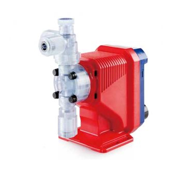
Iwaki EWN — R
- высокоскоростные дозирующие насосы высокого разрешения со встроенным цифровым многофункциональным контроллером;
- различные варианты напряжения питания переменного тока;
- широкий выбор головок насоса;
- производительность: от 38 до 420 мл/мин;
- макс. давление подачи: от 0,2 до 1,0 Мпа.
Iwaki EH — E
- дозирующие насосы высокого разрешения для больших потоков;
- встроенный контроллер с микрокомпьютером;
- пыле- влагозащищенное исполнение по IP65;
- высокая химическая стойкость;
- производительность: от 340 до 1250 мл/мин;
- макс. давление подачи: от 0,2 до 1,0 Мпа.
У нас вы также можете купить дозирующие насосы Iwaki Pumps серий:
EHN-Y
EWN-R-H2
EWN-A
EWN-W
EWN-Y
EWN-Y-A
ETU
Преимущества
лучшая цена
экспресс-доставка
фирменная гарантия
подбор по параметрам
Мы сочетаем оперативность обработки заказа и быструю доставку.
Доставляем ушедшие из РФ бренды напрямую из США и Европы. Есть вопросы? Напишите нам в WhatsApp!
×
Сейчас вы находитесь в городе Москва
Выберите город, в который Вы хотите осуществить доставку

28 290₽

29 990₽

99 990₽

36 790₽

28 290₽

21 390₽

37 490₽

28 290₽
iwaki walchem eh e metering pump ehe56e1 vc, а также миллионы оригинальных товаров с возможностью доставки в Москву, Санкт-Петербург и другие города России.
Есть вопросы? Спросите нас!

472 690₽

250 090₽

83 390₽

166 590₽

54 190₽

91 690₽

496 490₽

21 190₽

49 190₽

173 390₽

109 990₽

41 290₽

74 990₽

600 190₽

85 390₽

29 990₽

49 990₽

66 790₽

38 090₽

27 490₽

600 190₽

27 290₽

84 990₽

19 990₽

22 790₽

28 990₽

24 490₽
![iwaki walchem ehc35r1-fc metering pump ehc-c11upr controller [4*J-23]](https://i.ebayimg.com/00/s/MTIwMFgxNjAw/z/0joAAOSw2LlaoI2c/$_1.JPG)
12 490₽

165 890₽

52 790₽

25 790₽

166 590₽

108 390₽

7 090₽

43 290₽

79 190₽
В чем наша ценность
Покупки без ограничений
- Доставка в любой город СНГ
- Простой процесс оплаты
- Каталог на русском языке
Доступ к 3 млн. товаров
- Доставка в любой город СНГ
- Простой процесс оплаты
- Каталог на русском языке
Консолидация и сервис
- Доставка в любой город СНГ
- Простой процесс оплаты
- Каталог на русском языке
Покупки в США и Европе — это просто
Вы делаете заказ — мы выкупаем товары и доставляем вам
Склад

$46
Косметика M.A.C.maccosmetics.com

$46
Часы Timexamazon.com

$15
Джинсы levi’sebay.com
К вам домойОтправляем в Россию и
во все страны СНГ
Начать выгодные покупки в зарубежных интернет-магазинах