![]() Скачать бесплатно руководства по ремонту автомобилей в PDF формате
Скачать бесплатно руководства по ремонту автомобилей в PDF формате
Электронные книги : Руководства по ремонту, советы по эксплуатации, ремонту двигателей и электрооборудования, технические характеристики различных марок автомобилей
Скачать бесплатно электронные книги , инструкции и руководства по ремонту автомобилей, книги по ремонту и эксплуатации автомобилей, и другие автокниги, а также автокаталоги, карты, атласы, учебные пособия для подготовки водителей, CD диски по автомобильной тематике, каталоги запчастей для автомобилей, автокниги по ремонту, эксплуатации и обслуживанию автомобилей, как российских, так и зарубежных производителей, издательств технической литературы, таких как Третий Рим, Арус, Монолит, Мир Автокниг, За рулем, Легион Автодата
Acura, Alfa Romeo, Audi, Beifan Benchi, BMW, Buick, BYD, Cadillac, Chery, Chevrolet, Chrysler, Citroen, Dacia, Dadi, Daewoo, DAF, Daihatsu, Derways, Dodge, Dong Feng, FAW, Fiat, Ford, Foton, Freightliner, Geely, GMC, Great Wall, Groz, Hania, Hino, Holden, Honda, HOWO, Hummer, Hyundai, Infiniti, International, Iran, Isuzu, Iveco, Jeep, Kenworth, Kia, Lancia, Land Rover, Range Rover, Lexus, Lifan, Lincoln, MAN, Maxus, Mazda, Mercedes-Benz, Mercury, Mini, Mitsubishi, Nissan, Oldsmobile, Opel, Peterbilt, Peugeot, Plymouth, Pontiac, Porsche, Renault, Rover, Saab, Samsung, Saturn, Scania, Scion, Seat, Setra, Shaanxi, Skoda, SsangYong, Subaru, Suzuki, TagAZ, Tata, Toyota, VolksWagen, Volvo, Vortex, ZAZ, АЗЛК, Москвич, ВАЗ, Lada, ГАЗ, Донинвест, ЗИЛ, Иж, КамАЗ, КрАЗ, ЛиАЗ, ЛуАЗ, МАЗ, МЗКТ, ПАЗ, УАЗ, УРАЛ
- Manuals
- Brands
- Iveco Motors Manuals
- Engine
- Cursor 13 Series
- Use and maintenance
-
Contents
-
Table of Contents
-
Bookmarks
Quick Links
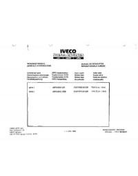
MARINE ENGINES
Publication edited by
Marketing — Adv. & Promotion
Print L31900013 — 12/05
USE AND MAINTENANCE
USO E MANUTENZIONE
UTILISATION ET ENTRETIEN
BETRIEB UND WARTUNG
USO Y MANTENIMIENTO
CURSOR 13
SERIES
Related Manuals for Iveco Motors Cursor 13 Series
Summary of Contents for Iveco Motors Cursor 13 Series
-
Page 1
USE AND MAINTENANCE USO E MANUTENZIONE UTILISATION ET ENTRETIEN BETRIEB UND WARTUNG USO Y MANTENIMIENTO CURSOR 13 SERIES MARINE ENGINES Publication edited by Marketing — Adv. & Promotion Print L31900013 — 12/05… -
Page 2
CURSOR 13 SERIES FOREWORD Thank you for choosing IVECO MOTORS and congratulations for your choice of engine. Before carrying out any operation involving the engine and its C13 ENT M50 equipment, please read carefully the instructions contained in this C13 ENT M77 manual. -
Page 3: Table Of Contents
TABLE OF CONTENTS Page Page GENERAL……… . 3 ENGINE FAILURES .
-
Page 4: General
Using non genuine spare parts may cause the guarantee to decay and electric equipment is subject to voltage and electric currents. waives any IVECO MOTORS liability for the entire life of the engine. Engine exhaust gases can be dangerous for health.
-
Page 5: C13 Ent M50 Engines Technical Data
C13 ENT M50 ENGINE TECHNICAL DATA Available ratings (*) C13 ENT M50 The technical acronym and the serial number are specified on the nameplate which — based on the model — can be found on different 382 kW (520 CV) @ 2000 rpm parts of the engine: flywheel casing, tappet cover, coolant pan.
-
Page 6
05_102_C 05_101_C CURSOR C13 ENT M50 Engine CURSOR C13 ENT M50 Engine 1. Air filter — 2. Fuel filters switch lever (opt.) — 3. Fuel filter — 4. Air-sea water 1. Location of thermostatic valve — 2. Coolant refill cap — 3. Lifting padeye — 4. heat exchanger — 5. -
Page 7: C13 Ent M77 Engines Technical Data
Engine rotation direction Counterclockwise fittings. Any non observance of the above shall null any warranty and (from flywheel side) IVECO MOTORS liability. Weight without liquids 1380 kg Electrical system 24 V…
-
Page 8
05_104_C 05_103_C CURSOR C13 ENT M77 Engine CURSOR C13 ENT M77 Engine 1. Air filter — 1. Fuel filters switch lever (opt.) — 3. Fuel filter — 4. Air-sea water 1. Location of thermostatic valve — 1. Coolant refill cap — 2. Lifting padeye — 3. -
Page 9: Labels
LABELS Below you can find the explanation of the caution labels located on the engine. NOTE: Labels with an exclamative point highlight a potential danger. Lifting point (engine only). Burn hazard: Pressurised hot water expulsion. Fuel refill plug Burn hazard: (on tank, if available).
-
Page 10: Use
STARTING AND STOPPING THE ENGINE For boats equipped with instrument panel not manufactured by IVECO MOTORS PRELIMINARY TESTING Startup and stop procedures described below are provided assuming Before each engine startup: a genuine IVECO MOTOR instrument panel is assembled on board.
-
Page 11: Starting And Stopping The Engine From An Analog Instrument
STARTING AND STOPPING THE ENGINE FROM AN ANALOG INSTRUMENT PANEL Startup procedure from IVECO MOTORS main panel (provided upon request) Make sure that the electric switch with ENGINE ROOM — BRIDGE label on the Relay box unit, (usually located in the engine room) is turned to BRIDGE, then proceed as follows: 1.
-
Page 12
WARNING For the onboard control panels to fully perform their relevant operations during navigation, it is essential that the engine startup is done only after the completion of warning lights and horn testing. Startup procedure from IVECO MOTORS secondary panel or fly-bridge (provided upon request) 1 Enable the secondary panel operation by turning the key switch on the main panel to 8B position (see instructions and procedure described in the previous paragraph). -
Page 13
A. To stop the engine from IVECO MOTORS main panel, turn the key switch to the stop position 8A or act on any similar control if your boat is equipped with a customized dashboard. -
Page 14: Recognizing Alarm Statuses
RECOGNIZING ALARM STATUSES IVECO MOTORS onboard panels equipped with analog instruments include an electronic module with indicator lights and interface circuits, timing and saving of alarms. The figure shows the module quadrant and the legend contains the meaning of the alarm pictorial corresponding to each light indicator; in some engine type and relevant fitting are not equipped with all of the features mentioned herein.
-
Page 15: Starting And Stopping The Engine From Digital Instrument Panel
STARTING AND STOPPING THE ENGINE FROM A DIGITAL INSTRUMENT PANEL (C13 ENT M50 engine only) Startup procedure from IVECO MOTORS main panel (provided upon request) Make sure that the electric switch with ENGINE ROOM — BRIDGE label on the Relay box unit, (usually located in the engine room) is turned to BRIDGE, then proceed as follows: 1.
-
Page 16
Startup procedure from IVECO MOTORS secondary panel or (provided upon request) fly-bridge 1. Enable the secondary panel operation by turning the key switch on the main panel to 8B position (see instructions described in the previous paragraph). 2. Wait for the acoustic alarm to stop and that the warning lights (5) on the signaling module are switched off (except for «alternator anomaly»… -
Page 17: Recognizing Alarm Statuses
Moreover these instructions may change A. From the IVECO MOTORS main panel: rotate the key based on the technical features provided by the boat manufacturer.
-
Page 18
Operation Detail of the main panel By rotating the key switch to 8B position the module performs a 5 seconds efficiency test of all light indicators, except for those concerning “Pre-lubrication”, “Pre-post heating”, “EDC system fault”, and the horn beeps. The beep may be silenced before the end of the test, by pushing the relevant button. -
Page 19
C13 ENT M50 In case the information set does not correspond to what provided for the type of oil used (see REFUELLING and FREQUENCY), proceed Maximum power(CV) Maximum insertion (mg/strk) as follows: — After having displayed the hour information previously set, release the push buttons and repeatedly press only the «Slide selection»… -
Page 20: Engine Management From C13 Ent M50 Relay Box
ENGINE MANAGEMENT FROM RELAY BOX (C13 ENT M50 engine only) WARNING! The engine fitting includes a «Box relay» unit which is usually located When the engine is rotating, do not operate the ENGINE near the engine room and which provides management of the ROOM / BRIDGE switch.
-
Page 21: Engine Management From C13 Ent M77 Relay Box
Stop procedure ENGINE MANAGEMENT FROM RELAY BOX 1. Press the 2 push button to STOP position until the engine is (C13 ENT M50 engine only) completely stopped. The engine fitting includes a «Box relay» unit which is usually located near 2.
-
Page 22: For A Correct Use Of The Engine
Startup procedure FOR A CORRECT USE OF THE ENGINE 1. Turn the switch to 1 ENGINE ROOM. The START-STOP (2) push Do not extend the startup control when the engine is started. button nearby is enabled; this action disables any function of Do not remain at the quay to wait for engine warm-up.
-
Page 23: Special Warnings
SPECIAL WARNINGS Water in the fuel pre-filter Coolant high temperature It’s a good habit to drain the water inside filters before the relevant led turns on. In case the temperature on the instrument is excessive or an alarm is Avoid using the engine when the tank contains only the reserve fuel; off, reduce speed and return to the harbor and check the sea water such condition fosters the formation of condensation and the suction intake and cooling circuits status.
-
Page 24: Running-In
Alternator anomaly RUNNING-IN Periodically check or have checked the cleaning, wear and tensioning Thanks to the engine construction advanced technology, non special condition of the tensioning belt. running-in procedure is required. However it is recommended to avoid at least for the first 50 hours, using the engine at high speeds for extended periods of time.
-
Page 25: Refuelling
REFUELING from the synthesis of organic substances and vegetable oils (Biodiesel) is not allowed. Parts to be refueled C13 ENT ..liters (kg) WARNING Cooling circuit Refuelling from drums or tanks may pollute diesel oil and therefore damage the injection system. If necessary filter or settle impurities Cooling circuit before refueling.
-
Page 26: Inspections And Maintenance
Do not leave foreign bodies on the engine. a wrench (see picture). Use suitable and safety container for exhaust oil. Authorized Servicing Centers are members of IVECO MOTORS When the repair is finished, take the necessary steps to stop engine Customer Care Network.
-
Page 27: Frequency
WARNING! Periodical maintenance: Frequency Avoid performing maintenance near a power source: check that the equipment is efficiently grounded. During (2) (7) Air filter/s cleaning 300 hours diagnosis and maintenance operations make sure hands (4) (7) Zinc anodes corrosion 300 hours and feet are dry and always use insulating footboards.
-
Page 28
6) Comburent air/sea water exchanger: clean both air and water sections; engine coolant/sea water exchanger: clean the sea water section; inverter oil/sea water exchanger (if available): clean the sea Extraordinary maintenance Frequency water section. 7) To be performed every year even if the operating hours expected Check sea water pump rotor wear 1200 hours are not met. -
Page 29: Prescriptions
PRESCRIPTIONS HOW TO 1. Do not disconnect battery power when the engine is running. Engine lubricant level inspection 2. Do not perform arch soldering near the engine without having Proceed only with engine stopped and at low temperature to avoid removed al electric connections and electronic units.
-
Page 30
Water drain from fuel pre-filter The high risk of refueling with fuel polluted with foreign bodies and WARNINGS water requires inspections to be performed even if no alarm is triggered on the on board panel. After refilling make sure oil level does not exceed «Max» on the stick. Proceed with engine not running. -
Page 31
Air filter/s cleaning Request an efficiency diagnosis of the battery recharge system if when the engine is running the voltage is lower than 22 V. Remove the filter by removing the rod (1) and loosening the screws Check that terminals and clamps are clean, securely tight and (2) shown in the figure. -
Page 32
Zinc anodes corrosion inspection Engine lubricant replacement Proceed with engine not running and at low temperature: Proceed only with engine not running and at low temperature to avoid Place the necessary basins in order to avoid water to spill off during any risk of burns. -
Page 33
04_001_C 05_005_C With transfer electric system (optional) Place under the cock (5) a container to collect the exhaust oil. The above operations can be performed by acting on the push button Open the cock (1) and press (A) towards DISCHARGE, until it is located on the electronic module. -
Page 34
Efficiency testing of one-way valve in the pre- With transfer and pre-lubrication electric system (optional) lubrication system (image page 32) The above operations can be performed by acting on the push button located on the electronic module. Fore safety reasons controls are Proceed with engine not running. -
Page 35
Place under the cock (1) a container to collect the exhaust oil. Remove filters. Accurately clean surfaces. Moist seals of the new filters with some oil. Manaully tighten until contact is made, then tighten again for 3/4 of turn. Dispose drained liquids observing current regulations in… -
Page 36
Fuel filter/s replacement Proceed only with engine not running and at low temperature to avoid any risk of burns. Use only filters with filtering degree equal to the above ones (see FREQUENCY). With traditional filter support Remove filter (1) by unscrewing it. Moist seals of the new filters with diesel or engine oil. -
Page 37
Fuel pre-filter/s replacement Proceed only with engine not running and at low temperature to avoid any risk of burns. Remove pre-filter unscrewing it. Unscrew the water sensor (3) from the old pre-filter. Check that the new filter matches the engine requirements. Moist seals of the new filters with diesel or engine oil. -
Page 38
Check tension and conditions of auxiliary parts belt Coolant replacement Proceed only with engine not running and at low temperature to Proceed only with engine not running and at low temperature to avoid avoid any risk of burns. any risk of burns. Remove pulley protection. -
Page 39
WARNING Only IVECO MOTORS Servicing Centers or Yard staff may perform the following operations. Please refer to the relevant technical and repair manuals. Condensation draining/suction from fuel tank/s Sea water intake inspection Check sea water pump rotor wear 84377 Check the efficiency of the pre-post heating system… -
Page 40: Moving The Engine
MOVING THE ENGINE EXHAUST PARTS DISMISSAL Only Authorized Servicing Center staff can perform such operations. The engine assembly includes parts and items which may cause To lift only the engine use the eyelets specified herein in the ecological damages if released in the environment. ENGINE TECHNICAL DATA section.
-
Page 41: Long Engine Inactivity
LONG ENGINE INACTIVITY 9. Drain coolant, and place a label stating the operation has been completed. ENGINE PREPARATION FOR LONG INACTIVITY In case of extended inactivity, repeat the above every 6 month, as PERIODS follows: In case of prolonged inactivity and order to avoid oxidation of internal A) Drain from 30/M protective oil;…
-
Page 42
COMMISSIONING AFTER EXTENDED PERIOD OF INACTIVITY 1. Drain any residual 30/M protective oil. 2. Fill the engine with lubricating oil as provided in REFUELLING table. 3. Drain any protective liquid from the fuel circuit and follow the instructions provided in point 3 ENGINE PREPARATION FOR LONG INACTIVITY PERIODS. -
Page 43: Engine Failures
ENGINE FAULTS WARNING! The electronic unit overseeing management and control of all operation of the engine is capable of recognising any malfunctions that The engine electronic unit may adopt safety strategies any may occur, and of adopting strategies that will allow you to navigate in time during navigation, whenever any risk condition for the full safety.
-
Page 44: Emergency On Board
EMERGENCY ON BOARD Burns 1. Extinguish flames on clothing using: The boat user, if observing the instructions contained in this manual, • water; will always be acting in safe conditions. • dust fire extinguisher; In case of accident, always request the immediate intervention of •…
-
Page 45
Electrocution Skin burns The electric system does not involve electrocution however in case of This may result from contact with acid substances. short circuit, some risk of burn may arise. In such case: This usually happens when liquid flows out of the battery. In such case: 1. -
Page 47
ON BOARD PANELS REQUIREMENTS The following refers to the original configuration of IVECO MOTORS equipment. The requirements and technical features of customizations may be different. Refer to the original manufacturer for further information. IVECO MOTORS on board panels With analog instruments…
Автомануалы » Руководства » Скачать руководство по ремонту и обслуживанию Iveco Stralis Cursor
|
Размещено: 17 ноября 2008 Просмотров: 21 641 Комментариев: 1
Скачать руководство по ремонту и обслуживанию Iveco Stralis Cursor
Руководство по ремонту и техническому обслуживанию автомобиля Iveco Stralis Cursor на русском языке с электрическими схемами. Язык: русский Скачать руководство по ремонту + электрические схемы Iveco Stralis Cursor: Внимание! У Вас нет прав для просмотра скрытого текста. |
Вы можете прямо сейчас зарегистрироваться или авторизоваться на сайте под своим именем.
ПОСЛЕДНИЕ
ТОП
КОММЕНТАРИИ
Руководство на английском языке по ремонту двигателей Iveco Cursor.
- Автор: —
- Издательство: Motorist
- Год издания: —
- Страниц: 367
- Формат: —
- Размер: —
Руководство на английском языке по техническому обслуживанию и ремонту двигателей Iveco C10/C13/C78/Cursor 10/Cursor 13.
- Автор: —
- Издательство: Iveco
- Год издания: 2007
- Страниц: 398
- Формат: PDF
- Размер: 26,9 Mb
Руководство на английском языке по техническому обслуживанию и ремонту двигателей Iveco C87/Cursor 87.
- Автор: —
- Издательство: Iveco
- Год издания: 2007
- Страниц: 216
- Формат: PDF
- Размер: 23,5 Mb
Руководство на английском языке по техническому обслуживанию и ремонту двигателей Iveco N45/N67
- Автор: —
- Издательство: Iveco
- Год издания: 2006
- Страниц: 186
- Формат: PDF
- Размер: 8,8 Mb
Руководство на английском языке по техническому обслуживанию и ремонту двигателей Iveco C10/C13/C78/Cursor 13/Cursor 78.
- Автор: —
- Издательство: Iveco
- Год издания: 2006
- Страниц: 552
- Формат: PDF
- Размер: 28,4 Mb
Руководство на английском языке по техническому обслуживанию и ремонту двигателя Iveco Vector 8.
- Автор: —
- Издательство: Iveco
- Год издания: 2006
- Страниц: 206
- Формат: PDF
- Размер: 13,7 Mb
Руководство на английском, итальянском, французском и немецком языках по техническому обслуживанию и ремонту двигателя Iveco модели 8131.
- Автор: —
- Издательство: Iveco
- Год издания: —
- Страниц: 160
- Формат: PDF
- Размер: 7,2 Mb
Руководство на испанском языке по техническому обслуживанию и ремонту двигателя F1C автомобиля Iveco Daily с 2007 года выпуска.
- Автор: —
- Издательство: Iveco
- Год издания: —
- Страниц: 191
- Формат: PDF
- Размер: 6,5 Mb
Спецификация на английском языке двигателя Iveco C10 ENT.
- Автор: —
- Издательство: Iveco
- Год издания: 2004
- Страниц: 22
- Формат: PDF
- Размер: 801 Kb
Спецификация на английском языке двигателей Iveco C87/Cursor 87 TE X.
- Автор: —
- Издательство: Iveco
- Год издания: 2007
- Страниц: 24
- Формат: PDF
- Размер: 1,6 Mb

Спецификация на английском языке двигателя Iveco S23 ENT C.
- Автор: —
- Издательство: Iveco
- Год издания: 2005
- Страниц: 28
- Формат: PDF
- Размер: 1,4 Mb
Спецификация на английском языке двигателя Iveco S30 ENT C.
- Автор: —
- Издательство: Iveco
- Год издания: 2006
- Страниц: 24
- Формат: PDF
- Размер: 1,1 Mb

-
Содержания книг
- Содержание Инструкция по ремонту Iveco Stralis Cursor
СОДЕРЖАНИЕ КНИГИ РУКОВОДСТВО ПО РЕМОНТУ И ТЕХНИЧЕСКОМУ ОБСЛУЖИВАНИЮ IVECO STRALIS CURSOR 10 / CURSOR 13
ГЛАВА 1. ВВЕДЕНИЕ
ГЛАВА 2. ДВИГАТЕЛЬ
Cursor 13
Технические характеристики 21
Моменты (Нм) и угловые значения
затяжки основных резьбовых соединений 34
Cursor 10
Технические характеристики 38
Моменты (Нм) и угловые значения затяжки основных резьбовых соединений 48
Cursor 13 Рекомендации по выполнению операций
Снятие и установка двигателя 51
Головка блока цилиндров 58
Седла клапанов 62
Клапаны 63
Клапанные пружины 63
Замена втулок форсунок 64
Распределительный вал 65
Подшипники распределительного вала 65
Сборка и установка головки блока 67
Рампа коромысел 68
Регулировка зазора клапанов привода насос-форсунок 70
Блок цилиндров 73
Гильзы цилиндров 74
Подшипники коленчатого вала 78
Подшипники распределительного вала 79
Масляные форсунки 79
Подвижные системы двигателя 81
Коленчатый вал 81
Узел шатун-поршень 86
Маховик двигателя 90
Картер маховика двигателя 92
Механизм распределительных шестерен 94
Проверка и регулировка распределительного вала 97
Регулировка импульсного кольца 98
Уплотнение «переднего» подшипника 98
Система смазки 100
Масляный насос 102
Перепускной клапан 103
Теплообменник 103
Масляные фильтры 105
Перепускной клапан 105
Система охлаждения 106
Водяной насос 106
Термостат 106
Контур системы охлаждения 108
Система литания 109
Контроль регулировки 110
Насосы-форсунки 110
Топливоподкачивающий насос 111
Продувка топливной системы 112
Дополнительное оборудование 113
Воздушный компрессор и насос сервопривода рулевого управления. 113
Продувка контура сервопривода рулевого механизма 113
Моторный тормоз 113
Система наддува 114
Неисправности в работе 117
Электромагнитный клапан «VGT». 117
Снятие и установка турбокомпрессора 117
Неисправности и возможные причины 118
Cursor 10 Рекомендации по выполнению операций
Снятие и установка двигателя 120
Головка блока цилиндров 122
Работы на головке блока цилиндров 123
Проверка герметичности 123
Разборка 124
Клапаны 124
Седла клапанов 126
Направляющие 126
Клапанные пружины 127
Замена втулок форсунок 127
Распределительный вал 128
Подшипники распределительного вала 128
Сборка головки блока цилиндров 129
Установка головки 129
Стойка коромысел 130
Регулировка зазоров клапанов привода насосов-форсунок 131
Блок цилиндров 134
Гильзы цилиндров 134
Подшипники коленчатого вала 137
Подшипники распределительного вала 139
Толкатели 139
Подвижная система двигателя. 141
Коленчатый вал 141
Узел шатун-поршень 146
Маховик двигателя 149
Задний сальник коленчатого вала 151
Передний сальник 151
Картер маховика двигателя 151
Механизм распределительных шестерен 152
Проверка и регулировка распределительного вала 154
Передний сальник 156
Система смазки 157
Масляный насос 157
Теплообменник 158
Система охлаждения 160
Водяной насос 160
Термостат 160
Система питания 162
Контроль регулировки 163
Насосы-форсунки 163
Декомпрессионный тормоз 164
Система наддува 165
Неисправности в работе 167
Регулировка подвижного элемента 168
Электромагнитный клапан привода «VGT 168
ГЛАВА 3. СЦЕПЛЕНИЕ
Технические характеристики 169
Профилактическое обслуживание 169
Моменты (Нм) и угловые значения затяжки основных резьбовых соединений 170
Рекомендации по выполнению операций
Снятие и установка сцепления 171
Проверка диска сцепления 172
Контроль и регулировка ограничителей педали сцепления 173
Ход распределителя 174
Рабочий цилиндр привода сцепления 174
Монтаж и регулировка индикатора износа 174
Регулировка рабочего цилиндра (новый механизм сцепления) 176
Рабочий цилиндр привода сцепления (КПП Euro Tronic Automated) 177
Монтаж рабочего цилиндра сцепления 178
Замена рабочего цилиндра привода сцепления 178
ГЛАВА 4. КОРОБКА ПЕРЕКЛЮЧЕНИЯ ПЕРЕДАЧ ZF16S 181/221
Технические характеристики 182
Моменты затяжки основных резьбовых соединений (Нм) 184
Рекомендации по выполнению операций
Буксировка 185
Снятие и установка КПП в сборе (совместно или без устройства intarder) 186
Снятие реле 188
Разборка основного картера 188
Ремонт валов 190
Первичный вал 190
Вторичный вал 192
Регулировка зазора синхронизации входного реле 194
Промежуточный вал 196
Сборка КПП 197
Масляный насос 198
Регулировка осевого зазора подшипника промежуточного вала 198
Выходное реле 199
Пневматический привод КПП 202
Привод переключения передач (устройство «servoshift) 204
Коробка переключения передач ZF EUROTRONIC AUTOMATED
Технические характеристики 206
ГЛАВА 5. ЗАДНИЙ МОСТ
Технические характеристики 209
Моменты (Нм) и угловые значения затяжки основных резьбовых соединений 210
Рекомендации по выполнению операций
Замена входной прокладки 211
Балка моста 211
Проверка ступиц 212
Проверка элементов 213
Установка ступиц 214
Коробка дифференциала 216
Ремонт дифференциала 216
Разборка корпуса ведущей шестерни 217
Проверка деталей 217
Регулировка зазора крышек подшипников 221
Регулировка и проверка контактора блокировки дифференциала 222
ГЛАВА 6. ПЕРЕДНИЙ МОСТ
Технические характеристики 224
Моменты затяжки основных резьбовых соединений (Нм) 226
Рекомендации по выполнению операций
Снятие и установка 228
Проверка на автомобиле 232
Тяги 232
Шаровые 232
Проверка зазора шарового пальца рулевого механизма 232
Снятие цапфы поворотного кулака 232
Замена подшипников цапфы поворотного кулака 233
Установка 234
Контроль и регулировка зазора между поворотным кулаком и осью 235
Параметры переднего моста 235
Ступицы передних колес 235
ГЛАВА 7. РУЛЕВОЕ УПРАВЛЕНИЕ
Технические характеристики 238
Рекомендации по выполнению операций
Снятие и установка картера рулевой передачи 239
Установка рулевой сошки 240
Продувка гидравлической системы 240
Измерение люфта рулевого колеса 241
Проверка максимального давления в контуре привода 241
Регулировка ограничителя поворота 242
ГЛАВА 8. ТОРМОЗНАЯ СИСТЕМА
Технические характеристики 243
Моменты затяжки основных резьбовых соединений (Нм) 249
Рекомендации по выполнению операций
Замена тормозных колодок 250
Снятие и установка 251
Снятие и установка тормозных дисков 252
ГЛАВА 9. ПОДВЕСКА
Технические характеристики 260
Моменты затяжки основных резьбовых соединений (Нм) 264
Рекомендации по выполнению операций
Снятие и установка передней листовой рессоры 266
Снятие и установка тяг передней подвески 266
Задняя подвеска 268
Пневматическое устройство 268
Запись в память значений уровня 269
ГЛАВА 10. ЭЛЕКТРООБОРУДОВАНИЕ
Перечень элементов электрических схем 272
Центральный блок предохранителей и реле 277
Перечень электрических схем (электросхемы) 279
КУПИТЬ КНИГУ РУКОВОДСТВО ПО РЕМОНТУ И ТЕХНИЧЕСКОМУ ОБСЛУЖИВАНИЮ ИВЕКО СТРАЛИС КУРСОР 10 / КУРСОР 13
© Автолитература 2008
Все материалы, опубликованные на сайте http://avtoliteratura.ru, фотоизображение или тексты, являются объектом авторского права. Торговые знаки и логотипы, а так же авторские и смежные права принадлежат их законным владельцам. Частичное или полное копирование текстов, слоганов и фотоизображений без письменного согласия владельцев сайта запрещено и влечет за собой ответственность согласно действующему законодательству
Главное отличие нашего магазина от всех других магазинов автокниги в том, что у нас действительно есть в наличии та автомобильная литература, которая представлена на сайте