-
Contents
-
Table of Contents
-
Bookmarks
Quick Links
ioLogik E2210 User’s Manual
Third Edition, January 2007
www.moxa.com/product
Moxa Technologies Co., Ltd.
Tel:
+886-2-8919-1230
Fax:
+886-2-8919-1231
Web:
www.moxa.com
MOXA Technical Support
Worldwide:
The Americas:
support@moxa.com.tw
support@moxa.com
Related Manuals for Moxa Technologies ioLogik E2210
Summary of Contents for Moxa Technologies ioLogik E2210
-
Page 1
E2210 User’s Manual Third Edition, January 2007 www.moxa.com/product Moxa Technologies Co., Ltd. Tel: +886-2-8919-1230 Fax: +886-2-8919-1231 Web: www.moxa.com MOXA Technical Support Worldwide: support@moxa.com.tw The Americas: support@moxa.com… -
Page 2
The software described in this manual is furnished under a license agreement, and may be used only in accordance with the terms of that agreement. Copyright Notice Copyright © 2007 MOXA Technologies Co., Ltd. All rights reserved. Reproduction without permission is prohibited. -
Page 3: Table Of Contents
LED Indicators ………………….1-7 Chapter 2. Initial Setup ………………..2-1 Hardware Installation ………………….2-2 Connecting the Power………………..2-2 Grounding the ioLogik E2210 ………………2-2 Connecting to the Network………………. 2-2 Setting the RS-485 Baudrate ………………2-2 Adding More I/O Channels ………………2-2 Software Installation………………….2-3 Chapter 3.
-
Page 4
Ethernet Configuration ………………..4-3 RS-485 Settings ………………….4-4 I/O Settings……………………… 4-4 DI Channels ……………………4-4 DO Channels …………………… 4-5 System Management ………………….4-6 Accessible IP Settings………………..4-6 SNMP Agent …………………… 4-7 Network Connection………………… 4-7 LCM ……………………….. 4-7 Change Password……………………4-8 Load Factory Default…………………. -
Page 5
Digital Input Structure ………………..F-2 Digital Output Structure ………………..F-2 Pin Assignment of Terminal Blocks ………………F-3 Appendix G. Restriction of Hazardous Substance Material Declaration….G-1 Appendix H. Service Information……………… H-1 MOXA Internet Services ………………… H-2 Technical Support E-mail Address …………….H-2 Website for Product Information …………….. -
Page 6: Chapter 1. Introduction
Introduction Chapter 1. The ioLogik E2210 is a stand-alone Active Ethernet I/O server that can connect sensors and on/off switches for automation applications over Ethernet and IP-based networks. The following topics are covered in this chapter: Overview Traditional Remote I/O Active Ethernet I/O Click&Go…
-
Page 7: Overview
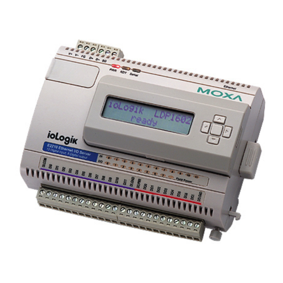
Overview (shown with and without optional LCM) The ioLogik E2210 is part of the E2000 line of ioLogik Active Ethernet I/O servers, which are designed for intelligent, pro-active status reporting of attached sensors, transmitters, transducers, and valves over a network. The ioLogik E2210 also supports an optional hot-pluggable Liquid Crystal Display Module (LCM), as shown above, to view and configure device settings.
-
Page 8: Optional Liquid Crystal Display Module (Lcm)
Display Module (LCM) for field management and configuration. The LCM can display network and I/O settings such as digital input mode and value. The ioLogik E2210’s IP address and netmask may also be configured using the LCM, and one LCM can be used to maintain and configure all your Easy View devices.
-
Page 9
E2210 User’s Manual Introduction Serial Communication Parameters Parity None Data bits Stop bits Flow control None Speed 1200 to 115200 bps Protocol Modbus/RTU Built-in RTC Digital Input Inputs 12, source type I/O Mode DI or Event Counter (input frequency: 100 Hz) -
Page 10: Physical Dimensions
E2210 User’s Manual Introduction Physical Dimensions Without LCD Module (unit: mm) 5.95 24.44 45.39 10.7 46.51 10.98 93.02 121.8 With LCD Module (unit: mm) 5.95 45.63 24.44 10.7 46.51 93.02 10.98 121.8…
-
Page 11: Hardware Reference
E2210 User’s Manual Introduction 44.5 35.1 57.5 Hardware Reference Panel Guide (TB1/TB2) (TB3) NOTE – The reset button restarts the server and resets all settings to factory defaults. Use a pointed object such as a straightened paper clip to hold the reset button down for 5 sec. The RDY LED will turn red as you are holding the reset button down.
-
Page 12: Led Indicators
(steady) ioLogik E2210 is functioning normally green (flashing) Click&Go ruleset is active green & red (flashing) ioLogik E2210 is in Safe Status Power is off or there is a power problem. Serial (flashing) Serial port is receiving/transmitting data DI x12 pins…
-
Page 13: Chapter 2. Initial Setup
Initial Setup Chapter 2. This chapter describes how to install the ioLogik E2210. The following topics are covered: Hardware Installation Connecting the Power Grounding the ioLogik E2210 Connecting to the Network Setting the RS-485 Baudrate Adding More I/O Channels Software Installation…
-
Page 14: Hardware Installation
Hardware Installation Connecting the Power Connect the 12 to 48 VDC power line to the ioLogik E2210’s terminal block (TB1). If power is properly supplied, the Power LED will glow a solid red color until the system is ready ATTENTION Disconnect the power before installing and wiring Disconnect the power cord before installing and/or wiring your ioLogik E2210.
-
Page 15: Software Installation
Search the network for the server: On the menu bar, select System Auto Scan Remote I/O Server. A dialog window will pop up. Click Start Search to begin searching for the ioLogik E2210. If ioAdmin is unable to find the ioLogik E2210, there may be a problem with your network settings.
-
Page 16
E2210 User’s Manual Initial Setup Monitoring I/O status: Once the ioLogik E2210 is found by ioAdmin, you may view the status of all I/O devices on ioAdmin’s main screen. You may now use ioAdmin to setup or configure your the ioLogik E2210. -
Page 17: Chapter 3. Using Ioadmin
Using ioAdmin Chapter 3. This chapter goes over the functions available in ioAdmin, the ioLogik E2210’s main configuration and management utility. The following topics are covered: Introduction to ioAdmin Features of ioAdmin ioAdmin Main Screen Main Screen Overview Wiring Guide…
-
Page 18: Introduction To Ioadmin
Windows 2000/XP utility provided with your ioLogik E2210. ioAdmin’s graphical-user interface gives you easy access to all status information and settings. The ioLogik E2210 also supports configuration by web console and by optional LCM, but full configuration and management is only available through ioAdmin.
-
Page 19: Ioadmin Main Screen
This is ioAdmin’s main screen. The main window defaults to the I/O Configuration tab, which displays a figure of the ioLogik E2210 and the status of every I/O channel below it. The other tabs in the main window take you to server and network settings, and further functions are available when you log on as an…
-
Page 20: Wiring Guide
E2210. You may access the wiring guide by right-clicking the figure of the ioLogik E2210 in the I/O Configuration tab. Select “Wiring Guide” in the submenu to open a help file showing the wiring information and electrical characteristics of the ioLogik E2210.
-
Page 21: I/O Configuration Tab (General)
E2210 User’s Manual Using ioAdmin I/O Configuration Tab (General) The I/O Configuration tab shows the status of every I/O channel. This is the default tab when you first open ioAdmin. Server Info Tab Server information, such as firmware version, is displayed in the Server Info tab.
-
Page 22: Server Settings Tab (General)
The Message Monitor tab will display any TCP/UDP I/O messages received from the ioLogik E2210. When you install the ioLogik E2210 for the first time, the active I/O messaging ruleset will not have been defined yet, so there will be no messages in the Message Monitor Tab. Please refer to Chapter 5: Click&Go Logic for information on how to program the ioLogik E2210’s active I/O messaging system.
-
Page 23: Ioadmin Administrator Functions
When making configuration changes, you will need to click on Update or on Apply to save the changes. Some changes will require a restart of the ioLogik E2210 in order to take effect, and you will be given the option to restart the computer if necessary.
-
Page 24
NOTE: “1” is the minimum filter value. Configuring Digital Output Channels The ioLogik E2210 is equipped with 8 DO (digital output or sink) channels that can be set individually to “DO” or “Pulse Output” mode. In DO mode, the specification is as follows. -
Page 25
Power On Settings Use this field to set the initial behavior of the DI/O channel when the ioLogik E2210 is powered on. For DI channels in Event Counter mode, you may configure whether or not counting begins at power up. For DO channels in DO mode, you may configure whether or not the DO is set to OFF or ON at power up. -
Page 26: Server Settings Tab (Administrator)
Serial settings, SNMP settings, and Web Access settings for the ioLogik E2210. IP Settings: You can set up a static or dynamic IP address for the ioLogik E2210, as well as the subnet mask and gateway address. The Accessible IP screen can be used to control network access to the ioLogik E2210 and attached sensors.
-
Page 27: Firmware Update Tab
Use these fields to enable SNMP and set the read and write community strings. Web Access Settings: This field enables and disables the ioLogik E2210’s web console. The web console allows the configuration of many settings using a web browser that is directed to the server’s IP address. If the web console is not enabled in this field, you will not be able to access the web console.
-
Page 28: Watchdog Tab
E2210 loses its network connection for the amount of time specified in the timeout, the Host Connection Watchdog will switch the ioLogik E2210 to Safe Status and the DI/O channels will reset to their Safe Status settings. By default, the Watchdog is disabled. To enable the Watchdog, make sure Enable Host Connection Watchdog is checked, set the Timeout value, then click the Update button.
-
Page 29: Server Context Menu
E2210 User’s Manual Using ioAdmin Changes made in the Click&Go Logic tab are not effective until the ioLogik E2210 is restarted, just like changes made in other tabs. Note that when Click&Go Logic is being used, the range and units of I/O channel being used in Click&Go Logic may not be modified.
-
Page 30
Select this command to reload a configuration that was exported to a text file. You will need to restart the ioLogik E2210 in order for the new configuration to take effect. This command may be used to restore a configuration after loading the factory defaults, or to duplicate a configuration to multiple ioLogik E2210’s. -
Page 31
E2210 User’s Manual Using ioAdmin ATTENTION You can import the configuration file from a TFTP server. For example, you can run TFTP Client software, open the configuration file, and enter the remote server’s IP. Note that both ASCII and Octet mode are supported. -
Page 32: Chapter 4. Using The Web Console
Using the Web Console Chapter 4. You may use the ioLogik E2210’s built in web console to configure many options. The following topics are covered: Introduction to the Web Console Basic Settings Network Settings General Settings Ethernet Configuration RS-485 Settings…
-
Page 33: Introduction To The Web Console
Save/Restart in the navigation panel. If you restart the ioLogik E2210 without saving your configuration, the ioLogik E2210 will discard all submitted changes. Basic Settings On the Basic Settings page, you may set the ioLogik E2210’s system time or provide the IP address of a time server for time synchronization.
-
Page 34: Network Settings
With Watchdog enabled, the ioLogik E2210 will enter Safe Status after there is disruption in communication that exceeds the time specified. Ethernet Configuration On the Ethernet Configuration page, you may set up a static or dynamic IP address for the ioLogik E2210, as well as the subnet mask and gateway address.
-
Page 35: Rs-485 Settings
E2210 User’s Manual Using the Web Console RS-485 Settings On the RS-485 Settings page, you may view the serial communication parameters, but no configuration changes are allowed. The baudrate may only be configured by the physical dial on the back of the ioLogik E2210.
-
Page 36: Do Channels
Modbus command. Make sure that the Counter Filter is not set to 0, otherwise the counter will never be activated. You may use the Power On Setting field to specify the channel’s setting when the ioLogik E2210 is powered on, and the Safe Status Setting field to specify channel’s setting when the ioLogik E2210 enters Safe Status.
-
Page 37: System Management
System Management Accessible IP Settings On the Accessible IP Settings page, you may control network access to the ioLogik E2210 by allowing only specified IP addresses. When the accessible IP list is enabled, a host’s IP address must be listed in order to have access to the ioLogik E2210.
-
Page 38: Snmp Agent
On the SNMP Agent page, you may enable SNMP and set the read and write community strings. The ioLogik E2210 provides SNMP v2 (Simple Network Management Protocol) to allow monitoring of network and I/O devices with SNMP Network Management software. It is useful in building automation and telecom applications.
-
Page 39: Change Password
Before you set a password for the first time, it is a good idea to export the configuration to a file when you have finished setting up your ioLogik E2210. Your configuration can then be easily imported back into the ioLogik E2210 if you need to reset the ioLogik E2210 due to a forgotten password or for other reasons.
-
Page 40: Chapter 5. Click&Go Logic
Click&Go Logic Chapter 5. Click&Go Logic was developed by MOXA to provide an easy way to program your ioLogik E2210 for active I/O messaging. In the chapter, we will show you how Click&Go Logic works and how to use it to develop your active I/O messaging program.
-
Page 41: Overview
TCP/UDP messages may be configured for transmission to up to 10 computers simultaneously. Click&Go can also be used to map an input channel on one ioLogik E2210 to an output channel on another ioLogik E2210, for direct peer-to-peer communication. Up to five different IP addresses can be entered as the output destination.
-
Page 42: Click&Go Logic Basics
DO operation can also be automated through DI trigger conditions or mapped directly to a remote DI channel on another ioLogik E2210. In the main screen, you will see a list of the rules in the current ruleset. Double click on a rule to open that…
-
Page 43: Defining Logic Rules
Logic rules and peer-to-peer I/O rules. Logic rules are used for DI event-based triggers, whereas peer-to-peer I/O rules are used for mapping I/O channels between two ioLogik E2210 servers. The Equivalent Logic Statement at the bottom shows a real-time text-based summary of the rule that you are defining.
-
Page 44: Then Actions
E2210 User’s Manual Click&Go Logic THEN Actions Under the THEN column, you may set up to 3 actions that will be performed if the conditions under the IF column are satisfied. The 3 actions may be any combination of DI/O setting, SNMP trap, Active Message (by TCP/UDP), or E-mail.
-
Page 45
E2210 User’s Manual Click&Go Logic Active Message Select Active Message for active I/O messaging over TCP or UDP. Click the memo icon to configure the message and parameters. Note that TCP and UDP cannot be used at the same time within a ruleset – all rules must use the same protocol. -
Page 46
DNS server information in the Network Settings tab. Enter your own e-mail address in the From Address field. Under Mail Server Settings, you must configure the IP address of the SMTP server with your username and password. Since the ioLogik E2210 supports DNS, you may enter the domain name of the SMTP server. -
Page 47: Defining Peer-To-Peer I/O Rules
The peer-to-peer I/O function allows this operation to be mapped over Ethernet from a digital input on one ioLogik E2210 to the digital output on another ioLogik E2210. This allows a pushbutton in one location to have direct control of an LED in another room, building, or even city.
-
Page 48: Configuring Input For Peer-To-Peer I/O
Configuring Input for Peer-to-Peer I/O Configuring the peer-to-peer I/O input module will use up one Click&Go rule on the ioLogik E2210 providing the input channels. In the Click&Go tab, open a new rule’s configuration window and enable peer-to-peer I/O.
-
Page 49: Configuring Output For Peer-To-Peer I/O
I/O. Select “Output channel” and provide the DO channel that will mirror the remote input channel, the IP address of the input module (i.e., the remote ioLogik E2210), and the DI channel on the input module that will be mirrored.
-
Page 50: Working With Click&Go Rulesets
Download in the Ruleset Management bar. After the ruleset has been downloaded, you must restart the ioLogik E2210. You may do this by right clicking on the server name in the navigation panel in ioAdmin and selecting Restart. Do not use the reset button, as that will load all factory defaults and erase your ruleset from memory.
-
Page 51: Click&Go Logic And Peer-To-Peer I/O Demo
E2210 User’s Manual Click&Go Logic Click&Go Logic and Peer-to-Peer I/O Demo Scenario 1 In this scenario, we have two switches, one attached to DI(0) and one attached to DO(0). Very simply, we want DO(0) to automatically mirror DI(0)’s setting. Once the ruleset is downloaded onto the ioLogik E2210 and activated, the server handles all processing locally and there is no usage of network or host resources.
-
Page 52: Scenario 3
E2210 User’s Manual Click&Go Logic Click the memo button. The Message parameters window will appear. Click on Keyword Lookup. In the Variable List that pops up, click on <Server_time>. Click on Save. 10. Click on Download on the Ruleset Management Bar.
-
Page 53
Rule 0: Send I/O status to 192.168.127.3 In ioAdmin, make sure that you have searched for and selected the correct ioLogik E2210 server, at IP address 192.168.127.154. Also, make sure you are logged in on the Server Settings tab. Go to the Click&Go Logic tab. -
Page 54
Sensors at the water tank will connect to digital input channels at 192.168.127.154, and the digital output channels at 192.168.127.3 will connect to the control panel. As long as both ioLogik E2210’s are on and connected to the network, the status of digital output channels 0 and 1 at 192.168.127.3 will be a “mirror”… -
Page 55: Appendix A. Liquid Crystal Display Module (Lcm
Module (LCM) for easier field maintenance. The LCM is hot-pluggable and can be used to configure the network settings or display other settings. When plugged in, the LCM displays the ioLogik E2210 “home page,” and pressing any button takes you into the settings and configuration.
-
Page 56
I/O server. The disable option has no effect. WARNING Any configuration changes that are made through the LCM will not take effect until the ioLogik E2210 is restarted. -
Page 57: Appendix B. Modbus/Tcp Address Mappings
Modbus/TCP Address Mappings Appendix B. E2210 Modbus Mapping 0xxxx Read/Write Coils (Support Functions 1, 5, 15) Reference Address Data Type Description 00001 0x0000 1 bit CH0 DO Value 0: Off 1: On 00002 0x0001 1 bit CH1 DO Value 0: Off 1: On 00003 0x0002 1 bit…
-
Page 58
E2210 User’s Manual Modbus/TCP Address Mappings Reference Address Data Type Description 00031 0x001E 1 bit CH6 DO Pulse Operate Status 0: Off 1: On 00032 0x001F 1 bit CH7 DO Pulse Operate Status 0: Off 1: On 00033 0x0020… -
Page 59
E2210 User’s Manual Modbus/TCP Address Mappings Reference Address Data Type Description CH5 DI Clear Counter Value read always: 0 Write: 1: Clear counter value 00066 0x0041 1 bit 0: return Illegal Data Value CH6 DI Clear Counter Value read always: 0… -
Page 60
E2210 User’s Manual Modbus/TCP Address Mappings Reference Address Data Type Description CH5 DI Counter Overflow Status Read: 0: Normal 1: Overflow Write: 0: clear overflow status 00078 0x004D 1 bit 1: return Illegal Data Value CH6 DI Counter Overflow Status… -
Page 61: 1Xxxx Read Only Coils (Support Function 2
E2210 User’s Manual Modbus/TCP Address Mappings Reference Address Data Type Description 00096 0x005F 1 bit CH11 DI Counter Trigger : 0=Low to High, 1=High to Low 00097 0x0060 1 bit CH0 DI Counter Power-On Status 0: Off 1: On…
-
Page 62: 3Xxxx Read Only Registers (Support Function 4
E2210 User’s Manual Modbus/TCP Address Mappings 3xxxx Read Only Registers (Support Function 4) Reference Address Data Type Description 30001 0x0000 word CH0 DI Counter Value Hi-Word 30002 0x0001 word CH0 DI Counter Value Lo-Word 30003 0x0002 word CH1 DI Counter Value Hi-Word…
-
Page 63
E2210 User’s Manual Modbus/TCP Address Mappings Reference Address Data Type Description 40017 0x0010 word CH0 DO Pulse Low Signal Width 40018 0x0011 word CH1 DO Pulse Low Signal Width 40019 0x0012 word CH2 DO Pulse Low Signal Width 40020… -
Page 64: Function 8
E2210 User’s Manual Modbus/TCP Address Mappings Reference Address Data Type Description CH0 DI Mode 0: DI 1: Counter 40053 0x0034 word Others: return Illegal Data Value CH1 DI Mode 0: DI 1: Counter 40054 0x0035 word Others: return Illegal Data Value…
-
Page 65: Appendix C. Used Network Port Numbers
Used Network Port Numbers Appendix C. E2210/E2210 Network Port Usage Port Type Usage Web Server Modbus Communication SNMP BOOTPC DHCP 4800 Auto search 9020 Peer-to-Peer function Export/import file 9000 Active Message (Default) 9000 Active Message (Default)
-
Page 66: Appendix D. Snmp Mib Ii
SNMP MIB II Appendix D. RFC1213 MIB II Supported SNMP Variables MOXA provides an SNMP to I/O MIB file that can help you monitor I/O status with SNMP software. You can find the MIB file on the CDROM. System MIB SysDescr SysObjectID SysUpTime…
-
Page 67
E2210 User’s Manual SNMP Agents with MIB II IP MIB IpRoutingDiscards ICMP MIB IcmpInAddrMasks IcmpInRedirects IcmpOutEchoReps IcmpOutTimeExcds IcmpInDestUnreachs IcmpInSrcQuenchs IcmpOutEchos IcmpOutTimestampReps IcmpInEchoReps IcmpInTimeExcds IcmpOutErrors IcmpOutTimestamps IcmpInEchos IcmpInTimestamps IcmpOutMsgs IcmpTimestampReps IcmpInErrors IcmpOutAddrMaskReps IcmpOutParmProbs IcmpInMsgs IcmpOutAddrMasks IcmpOutRedirects IcmpInParmProbs IcmpOutDestUnreachs IcmpOutSrcQuenchs UDP MIB… -
Page 68
E2210 User’s Manual SNMP Agents with MIB II SNMP MIB snmpOutSetRequests snmpOutTraps MOXA IO MIB DI00-Filter DI05-Filter DI10-Filter DO03-Type DI00-Index DI05-Index DI10-Index DO04-Index DI00-Mode DI05-Mode DI10-Mode DO04-Mode DI00-Status DI05-Status DI10-Status DO04-Status DI00-Type DI05-Type DI10-Type DO04-Type DI01-Filter DI06-Filter DI11-Filter DO05-Index… -
Page 69: Appendix E. Factory Default Settings
Factory Default Settings Appendix E. The ioLogik E2210 is configured with the following factory defaults: Default IP address: 192.168.127.254 Default Netmask: 255.255.255.0 Default Gateway: 0.0.0.0 Communication watchdog: Disable Modbus TCP alive check Timeout: 60 secs DI Mode: 100 × 0.5 ms…
-
Page 70: Appendix F. Pinouts And Cable Wiring
Pinouts and Cable Wiring Appendix F. Ethernet Port Pinouts Signal Serial Port Pinouts E2210 RS-485 Network Adapter Pin Assignment I/O Device Wiring * DO PWR is for powering up the field Power LED. Note: If you are using dry contacts, you must connect “DI COM” to power. For testing purposes, you may connect “DI COM”…
-
Page 71: Digital I/O Structure
E2210 Series User’s Manual Pinouts and Cable Wiring Digital I/O Structure Digital Input Structure Digital Output Structure…
-
Page 72: Pin Assignment Of Terminal Blocks
E2210 Series User’s Manual Pinouts and Cable Wiring Pin Assignment of Terminal Blocks (TB1 TB2) (TB3)
-
Page 73: Appendix G. Restriction Of Hazardous Substance Material Declaration
The following table lists the hazardous substances and elements that are contained in this electronic information product. Product: ioLogik E2210 Toxic and Hazardous Substances and Elements Hexavalent…
-
Page 74: Appendix H. Service Information
Service Information Appendix H. This appendix shows you how to contact MOXA for information about the ioLogik E2210, and other products, and how to report problems. In this appendix, we cover the following topics. MOXA Internet Services Problem Report Form…
-
Page 75: Moxa Internet Services
E2210 User’s Manual Service Information MOXA Internet Services Customer satisfaction is our top priority. To ensure that customers receive the full benefit of our products, MOXA Internet Services has been set up to provide technical support, driver updates, product information, and user’s manual updates.
-
Page 76: Problem Report Form
E2210 User’s Manual Service Information Problem Report Form MOXA ioLogik E2210 Active Ethernet I/O Server Customer name: Company: Tel: Fax: Email: Date: MOXA Product: ioLogik E2210 Serial Number: _________________ Problem Description: Please describe the symptoms of the problem as clearly as possible, including any error messages you see.
-
Page 77: Product Return Procedure
E2210 User’s Manual Service Information Product Return Procedure For product repair, exchange, or refund, the customer must complete each of the following: Provide evidence of original purchase. Obtain a Product Return Agreement (PRA) from the sales representative or dealer.
Порядок получения заказа:
- Перед выездом уточните у Вашего менеджера весовые и объемные габариты заказа, чтобы правильно выбрать транспорт.
- Для получения заказа представителю организации необходимо иметь надлежащим образом оформленную доверенность на право получения материальных средств или печать организации и доверенность на право подписи от лица руководителя организации, кроме случаев, когда получателем является сам руководитель организации.
- Для получения Вашего заказа представителем транспортной (курьерской) организации необходимо:
- предоставить менеджеру, оформившему ваш заказ, отсканированную доверенность (содержащую печать и подпись руководителя организации), в которой будет указана транспортная (курьерская) компания осуществляющая перевозку по конкретно указанному вами счёту;
- при получении товара представитель транспортной (курьерской) компании обязан предоставить доверенность, подтверждающую его право на получение и перевозку товаров.
При получении товара на складе обязательно проверяйте все позиции заказа и их количество. Расписывайтесь в документах, только убедившись в получении всего товара.

Доставка нашим курьером:
Стоимость доставки в пределах МКАД составляет 600 руб. (до 3 кг.)
Стоимость доставки за МКАД ограничена зонами на карте и составляет от 1000 руб. до 1500 руб. за зону.
Доставка курьерской службой:
Доставка курьерской службой осуществляется до двери клиента. Доставку осуществляет EMS Russian Post
Доставка Почтой России осуществляется при условии оплаты наложенным платежом. Стоимость доставки заказа из Москвы в другие города России и СНГ рассчитывается непосредственно для конкретного заказа. Также Вы можете рассчитать стоимость доставки сами, воспользовавшись ценами транспортных компаний. Наилучшим вариантом будет — поручить нашим менеджерам подобрать оптимальный для Вас способ доставки, исходя из полученных от Вас данных по пункту назначения заказа и срокам доставки. Оплата стоимости доставки при отправке заказа ж/д и автомобильным транспортом может быть произведена Вами при получении груза. В случае доставки товара экспресс почтой, от Вас потребуется предоплата ее стоимости.

Доставка транспортными компаниями
Самовывоз заказа осуществляется с нашего склада по адресу: Россия, 117105, г. Москва, 1-ый Нагатинский проезд, д. 2
Для того, что бы самостоятельно забрать товар Вам нужно уточнить у Вашего менеджера готовность заказа к отгрузке и согласовать место и дату получения товара.
СЭКОНОМЬТЕ СВОЕ ВРЕМЯ — воспользуйтесь услугой «ПРЕДВАРИТЕЛЬНЫЙ ЗАКАЗ».
Для этого сообщите Вашему менеджеру дату и примерное время, когда Вы планируете забрать свой заказ. Мы заранее подготовим для Вас документы и соберем Ваш заказ на складе. Вам останется, МИНУЯ ОЧЕРЕДЬ, получить свой заказ.
Moxa Technologies ioLogik E2210 I/O Systems PDF User Guides and Manuals for Free Download: Found (3) Manuals for Moxa Technologies ioLogik E2210 Device Model (Operation & User’s Manual, Quick Installation Manual)
More I/O Systems Device Models:
-
Texmate
Tiger 320 Series
Mar-14-2016 DI-60 320 DS (NZ301)_UL_March 2016 Page 1Texmate, Inc. Tel. (760) 598-9899 • www.texmate.comA powerful, intelligent, 6-digit Programmable Meter Controller (PMC)with modular outputs, input signal conditioning and advanced softwarefeatures for monitoring, measurement, control and communication application …
Tiger 320 Series Controller, 44
-
CREVIS
FnIO G-Series
1 MODBUS Programmable I/O GN-9371/2/3 FnIO G-Series Copyright(C) CREVIS Co.,Ltd Support +82-31-899-4599 URL : www.crevis.co.kr Version 1 …
FnIO G-Series I/O Systems, 109
-
auto maskin
Marine Pro 400 Series
Publication P/N 1006423 Configuration Manual 400 Series / 200 Series DCU 410E Engine Controller, P/N 1006445 RP 410E Remote Panel, P/N 1006446 DCU 408E Engine Controller, P/N 1006510 RP 210E Remote Panel, P/N 1006476 DCU 210E Engine Controller, P/N 1006475 RP 220E Remote Panel, P/N 1006472 DCU 208E Engine Controller, …
Marine Pro 400 Series Marine Equipment, 99
-
Sun Microsystems
Fire 6800
Sun Microsystems, Inc.4150 Network CircleSanta Clara, CA 95054 U.S.A.Send comments about this document to: http://www.sun.com/hwdocs/feedbackSun Fire™6800 System andSun Fire CabinetRackmount Placement MatrixPart No. 816-2062-18June 2003, Revision 01 …
Fire 6800 Server, 66
Recommended Documentation:
Дискретный ввод
-
Количество каналов
12
-
Тип каналов
Влажный контакт (нормально открытый), сухой контакт
-
Режим работы
Дискретный вход или счетчик (до 900 Гц)
-
Сухой контакт
Логический «0»: замкнут на землюЛогическая «1»: открыт
-
Влажный контакт
Логический «0»: 0~3 В постоянного токаЛогическая «1»: 10~30 В постоянного тока
-
Напряжение изоляции
3 кВ постоянного тока
Дискретный вывод
-
Количество каналов
8
-
Тип выходов
Sink
-
Режим работы
Дискретный выход или генератор импульсов
-
Защита по напряжению
45 В постоянного тока
-
Защита по току
2.6 А (по 650 мА на каждый из 4 каналов)
-
Напряжение изоляции
3 кВ постоянного тока
-
Защита от перегрева
175°С
Интерфейс Ethernet
-
Порты Ethernet
1 порт 10/100 Мбит/с (разъем RJ45)
-
Напряжение изоляции
1.5 кВ
-
Протоколы
Modbus/TCP, TCP/IP, UDP, DHCP, BOOTP, SNMP, HTTP, CGI, SNTP, SMTP
Последовательный интерфейс
-
Интерфейс
RS-485-2w: Data+, Data-, GND (разъем — 3-контактная клемма)
-
Скорость передачи данных, бит/с
1200 ~ 115200
-
Биты четности
нет
-
Биты данных
8
-
Стоповые биты
1
-
Защита от импульсных помех, кВ
15
-
Протоколы
Modbus/RTU
Требования по электропитанию
-
Рабочее напряжение
12 ~ 36 В (пост.)
-
Потребление тока
203 мА при 24 В
-
Разъем электропитания
Клеммы
-
Диаметр кабеля
14AWG
Требования к окружающей среде
-
Рабочая температура, град. C
-10 ~ 60
-
Рабочая влажность, %
5 ~ 95
-
Температура хранения, град. C
-40 ~ 85
Наличие международных сертификатов
-
Безопасность
UL508
-
Электромагнитная совместимость (EMI)
EN 61000-3-2EN 61000-3-3EN 61000-4-2EN 61000-4-3EN 61000-4-4EN 61000-4-5EN 61000-4-6EN 61000-4-8EN 61000-4-11EN 61000-6-2EN 61000-6-4FCC Part 15 Subpart B Class A
-
Среднее время наработки на отказ (MTBF), часов
213673
Конструктивные свойства
-
Габаритные размеры, мм
115 x 79 x 45.6
-
Материал корпуса
Пластик
-
Масса нетто, г
250
1
w w w. m o x a . c o m
i n f o @ m o x a . c o m
Industrial I/O
ioLogik E2210
Specifications
Instant event messaging by TCP/UDP/email/SNMP-trap
›
Easy-to-use Click&Go™ Logic for local output control
›
12-point 24 VDC digital input with counter
›
8-point 24 VDC digital output with pulse output
›
PC-based configuration utility and web console
›
I/O control over Modbus/TCP and SNMP protocol
›
Windows/WinCE VB/VC.NET and Linux C APIs
›
Peer-to-Peer I/O without controller
›
Introduction
Simple Applications without Programming
The ioLogik E2210 can convert a trigger event result directly into a
digital alarm output. This can be set up using the ioAdmin UI to define
an IF-THEN-ELSE Logic rule, eliminating the need to write programs
for PCs or controllers.
Software Event Counter Input and Pulse Output
Each digital input can be independently configured for DI or Event
Counter mode, and output can be independently configured for DO or
Pulse Output mode.
Active Ethernet I/O with 12 digital inputs and 8 digital outputs
LAN
Ethernet: 1 x 10/100 Mbps, RJ45
Protection: 1.5 KV magnetic isolation
Protocols: Modbus/TCP, TCP/IP, UDP, DHCP, Bootp, SNMP (MIB for
I/O and Network), HTTP, CGI, SNTP
Serial Communication
Interface: RS-485-2w: Data+, Data-, GND
Serial Line Protection: 15 KV ESD for all signals
Serial Communication Parameters
Parity: None
Data Bits: 8
Stop Bits: 1
Flow Control: None
Baudrate: 1200 to 115200 bps
Protocol: Modbus/RTU
Digital Input
Channels: 12, source type
Sensor Type: NPN, Dry contact
I/O Mode: DI or Event Counter (up to 900 Hz)
Dry Contact:
• Logic 0: short to GND
• Logic 1: open
Wet Contact:
• Logic 0: 0 to 3 VDC
• Logic 1: 10 to 30 VDC (DI COM to DI)
Common Type: 12 points per COM
Isolation: 3K VDC or 2K Vrms
Counter/Frequency: 900 Hz
Digital Filtering Time Interval: Software selectable
Over-voltage Protection: 36 VDC
Digital Output
Channels: 8, sink type, 36 VDC, 200 mA
I/O Mode: DO or Pulse Output (up to 100 Hz)
Pulse Wave Width/Frequency: 10 ms/100 Hz
Over-voltage Protection: 45 VDC
Over-current Limit: 400 mA (typical)
Over-temperature Shutdown: 175°C (min.)
Output Current Rating: Max. 200 mA per channel
Isolation: 3K VDC or 2K Vrms
Power Requirements
Power Input: 24 VDC nominal, 12 to 48 VDC
Power Consumption: 282 mA typical @ 24 VDC
Physical Characteristics
Wiring: I/O cable max. 14AWG
Dimensions: 115 x 79 x 45.63 mm (4.53 x 3.11 x 1.8 in)
Weight: 215 g
Environmental Limits
Operating Temperature: -10 to 60°C (14 to 140°F)
Storage Temperature: -40 to 85°C (-40 to 185°F)
Ambient Relative Humidity: 5 to 95% (non-condensing)