- Manuals
- Brands
- Intel Manuals
- Computer Hardware
- Core 2 Duo Processor
Manuals and User Guides for Intel Core 2 Duo Processor. We have 8 Intel Core 2 Duo Processor manuals available for free PDF download: Datasheet, User Manual, Design Manual, Installation Instructions Manual
File Specifications:1272/1272347-core_2_duo.pdf file (02 Jun 2023) |
Accompanying Data:
Intel Core 2 Duo Processor Computer Hardware, Processor PDF Installation Instructions Manual (Updated: Friday 2nd of June 2023 05:54:47 AM)
Rating: 4.2 (rated by 92 users)
Compatible devices: ARRANDALE IB957, D845GRG, NUC6i7KYK, 2920, Pentium 4, S5000PAL, 486MIS, BX80571E5300 — Pentium 2.6 GHz Processor.
Recommended Documentation:
Installation Instructions Manual (Text Version):
(Ocr-Read Summary of Contents of some pages of the Intel Core 2 Duo Processor Document (Main Content), UPD: 02 June 2023)
-
Intel Core 2 Duo Processor User Manual
-
Intel Core 2 Duo Processor User Guide
-
Intel Core 2 Duo Processor PDF Manual
-
Intel Core 2 Duo Processor Owner’s Manuals
Recommended: ASBB Series, 3258, PXD 25 DCI, Digital Pocket Thermometer, WLS920
Links & Tools
-
IN/OUT 1STEREO LINKIN/OUT 2GAIN REDUCTION dB INPUT / OUTPUT LEVEL dB-24 -6 -4-12 -2-18 0 +6-6 +9COMPRESSOR / LIMITEREXPANDER/GATE CH 1dBOFF +1005020TRIGGERRELEASEGATETHRESHOLDdB-40 +2010-30-104:1dB621RATIOI/OENHANCERMETERdB-20 +20+10-100OUTPUTGAIN REDUCTION dB INPUT / OUTPUT LEVEL dB-24 -6 -4-12 -2-18 0 + …
S-com 4 63
-
DC-8297-03PREFACEThank you for your interest in the Z380™ Central Processing Unit (CPU) and itsassociated family of products. This Technical Manual describes programmingand operation of the Z380™ Superintegration™ Core CPU, which is found in theZ380 Microprocessor Unit (MPU), and products built aro …
Z80380 268
-
IQ-PIP-USP2ULTRA SERIESDesigned for use with PIP2-compatible amplifi ers*, the IQ-PIP-USP2 connects the amplifi er to the Crown Bus of an IQ System, allowing the amplifi er to be controlled and monitored via IQ. The IQ-PIP-USP2 offers an extensive list of features, including output signal delay for …
IQ-PIP-USP2 2
-
11111ASRock X58 Extreme MotherboardEnglishEnglishEnglishEnglishEnglishCopyright Notice:Copyright Notice:Copyright Notice:Copyright Notice:Copyright Notice:No part of this installation guide may be reproduced, transcribed, transmitted, or trans-lated in any language, in any form or by any means, except …
X58 EXTREME — 216
Operating Impressions, Questions and Answers:
![]()
Intel® CoreTM 2 Duo Processor and
Intel ® Q35 Express Chipset
Development Kit
User’s Manual
October 2007
Order Number: 318476-001US

INFORMATION IN THIS DOCUMENT IS PROVIDED IN CONNECTION WITH INTEL® PRODUCTS. NO LICENSE, EXPRESS OR IMPLIED, BY ESTOPPEL OR OTHERWISE, TO ANY INTELLECTUAL PROPERTY RIGHTS IS GRANTED BY THIS DOCUMENT. EXCEPT AS PROVIDED IN INTEL’S TERMS AND CONDITIONS OF SALE FOR SUCH PRODUCTS, INTEL ASSUMES NO LIABILITY WHATSOEVER, AND INTEL DISCLAIMS ANY EXPRESS OR IMPLIED WARRANTY, RELATING TO SALE AND/OR USE OF INTEL PRODUCTS INCLUDING LIABILITY OR WARRANTIES RELATING TO FITNESS FOR A PARTICULAR PURPOSE, MERCHANTABILITY, OR INFRINGEMENT OF ANY PATENT, COPYRIGHT OR OTHER INTELLECTUAL PROPERTY RIGHT. Intel products are not intended for use in medical, life saving, life sustaining, critical control or safety systems, or in nuclear facility applications.
Intel may make changes to specifications and product descriptions at any time, without notice.
Intel Corporation may have patents or pending patent applications, trademarks, copyrights, or other intellectual property rights that relate to the presented subject matter. The furnishing of documents and other materials and information does not provide any license, express or implied, by estoppel or otherwise, to any such patents, trademarks, copyrights, or other intellectual property rights.
Designers must not rely on the absence or characteristics of any features or instructions marked “reserved” or “undefined.” Intel reserves these for future definition and shall have no responsibility whatsoever for conflicts or incompatibilities arising from future changes to them.
Intel processor numbers are not a measure of performance. Processor numbers differentiate features within each processor family, not across different processor families. See http://www.intel.com/products/processor_number for details.
The Intel® CoreTM 2 Duo Processor and Intel ® Q35 Express Chipset Development Kit may contain design defects or errors known as errata which may cause the product to deviate from published specifications. Current characterized errata are available on request.
Hyper-Threading Technology requires a computer system with an Intel® Pentium® 4 processor supporting HT Technology and a HT Technology enabled chipset, BIOS and operating system. Performance will vary depending on the specific hardware and software you use. See http://www.intel.com/ products/ht/Hyperthreading_more.htm for additional information.
Contact your local Intel sales office or your distributor to obtain the latest specifications and before placing your product order.
Copies of documents which have an order number and are referenced in this document, or other Intel literature may be obtained by calling 1-800-548-4725 or by visiting Intel’s website at http://www.intel.com.
BunnyPeople, Celeron, Celeron Inside, Centrino, Centrino logo, Core Inside, FlashFile, i960, InstantIP, Intel, Intel logo, Intel386, Intel486, Intel740, IntelDX2, IntelDX4, IntelSX2, Intel Core, Intel Inside, Intel Inside logo, Intel. Leap ahead., Intel. Leap ahead. logo, Intel NetBurst, Intel NetMerge, Intel NetStructure, Intel SingleDriver, Intel SpeedStep, Intel StrataFlash, Intel Viiv, Intel vPro, Intel XScale, IPLink, Itanium, Itanium Inside, MCS, MMX, Oplus, OverDrive, PDCharm, Pentium, Pentium Inside, skoool, Sound Mark, The Journey Inside, VTune, Xeon, and Xeon Inside are trademarks or registered trademarks of Intel Corporation or its subsidiaries in the United States and other countries.
*Other names and brands may be claimed as the property of others. Copyright © 2007, Intel Corporation. All Rights Reserved.
|
Intel® CoreTM 2 Duo Processor and Intel ® Q35 Express Chipset Development Kit |
|
|
User’s Manual |
October 2007 |
|
2 |
Order Number: 318476-001US |

Contents—Intel Core 2 Duo Processor and Intel Q35 Express Chipset
Contents
|
1.0 About This Manual ……………………………………………………………………………………….. |
6 |
||
|
1.1 |
Content Overview…………………………………………………………………………………… |
6 |
|
|
1.2 |
Text Conventions …………………………………………………………………………………… |
6 |
|
|
1.3 |
Glossary of Terms and Acronyms………………………………………………………………… |
7 |
|
|
1.4 |
Support Options…………………………………………………………………………………….. |
8 |
|
|
1.4.1 |
Electronic Support Systems …………………………………………………………….. |
8 |
|
|
1.4.2 |
Additional Technical Support ……………………………………………………………. |
8 |
|
|
1.5 |
Product Literature ………………………………………………………………………………….. |
8 |
|
|
2.0 Development Kit Hardware Features …………………………………………………………….. |
10 |
||
|
2.1 |
Intel® Q35 Express Chipset Development Kit Overview…………………………………… |
10 |
|
|
2.2 |
System Block Diagram …………………………………………………………………………… |
11 |
|
|
2.3 |
Development Kit Inventory Checklists ………………………………………………………… |
12 |
|
|
2.4 |
Processor Support ………………………………………………………………………………… |
14 |
|
|
2.5 |
System Memory …………………………………………………………………………………… |
14 |
|
|
2.5.1 Dual Channel (Interleaved) Mode Configurations …………………………………. |
15 |
||
|
2.5.2 Single Channel (Asymmetric) Mode Configurations……………………………….. |
17 |
||
|
2.6 |
Back-Panel Connectors…………………………………………………………………………… |
18 |
|
|
2.6.1 |
Audio-Connectors……………………………………………………………………….. |
18 |
|
|
2.6.2 RJ-45 LAN Connector with Integrated LEDs………………………………………… |
19 |
||
|
2.6.3 |
USB Port ………………………………………………………………………………….. |
19 |
|
|
2.6.4 Coaxial S/PDIF In/Out Connector…………………………………………………….. |
19 |
||
|
2.6.5 |
eSATA Port ……………………………………………………………………………….. |
19 |
|
|
2.7 |
Debug Features……………………………………………………………………………………. |
20 |
|
|
2.7.1 |
Extended Debug Probe (XDP)…………………………………………………………. |
20 |
|
|
2.7.2 |
Power LEDs ………………………………………………………………………………. |
20 |
|
|
2.7.3 Port 80 POST Code LEDs ………………………………………………………………. |
20 |
||
|
2.7.4 |
Voltage Reference ………………………………………………………………………. |
21 |
|
|
2.8 |
Development Kit Major Connectors and Jumpers……………………………………………. |
21 |
|
|
2.8.1 |
Jumper Functions ……………………………………………………………………….. |
22 |
|
|
2.8.2 USB 2.0 Front Panel ……………………………………………………………………. |
22 |
||
|
2.8.3 |
1394a Header ……………………………………………………………………………. |
22 |
|
|
2.9 |
SPI Removal / Installation Technique …………………………………………………………. |
23 |
|
|
2.9.1 |
SPI Device Removal…………………………………………………………………….. |
24 |
|
|
2.9.2 |
SPI Device Installation …………………………………………………………………. |
24 |
|
|
3.0 Setting Up and Configuring the Development Kit …………………………………………….. |
26 |
||
|
3.1 |
Overview …………………………………………………………………………………………… |
26 |
|
|
3.2 |
Installing Board Standoffs ………………………………………………………………………. |
26 |
|
|
3.3 |
BTX Heatsink Setup with SRM ………………………………………………………………….. |
28 |
|
|
3.3.1 SRM Alignment on any BTX Board …………………………………………………… |
28 |
||
|
3.4 |
Board Setup and Configuration before Boot………………………………………………….. |
30 |
|
|
3.5 |
Post Codes Definitions……………………………………………………………………………. |
32 |
|
|
3.5.1 |
Normal Post Codes ……………………………………………………………………… |
32 |
Figures
|
1 |
Board Features ………………………………………………………………………………………….. |
11 |
|
2 |
Intel® Q35 Express Chipset Development Kit block diagram …………………………………… |
12 |
|
3 |
Memory Channel and DIMM Configuration …………………………………………………………. |
15 |
|
4 |
Dual Channel (Interleaved) Mode Configuration with 2x DIMMs ……………………………….. |
16 |
|
5 |
Dual Channel (Interleaved) Mode Configuration with 3x DIMMs ……………………………….. |
16 |
|
Intel® CoreTM 2 Duo Processor and Intel ® Q35 Express Chipset Development Kit |
||
|
October 2007 |
User’s Manual |
|
|
Order Number: 318476-001US |
3 |

Intel Core 2 Duo Processor and Intel Q35 Express Chipset—Contents
|
6 |
Dual Channel (Interleaved) Mode Configuration with 4x DIMMs………………………………… |
17 |
|
7 |
Single Channel (Asymmetric) Mode Configuration with 1x DIMM ………………………………. |
17 |
|
8 |
Single Channel (Asymmetric) Mode Configuration with 3x DIMMs……………………………… |
18 |
|
9 |
Back-panel Connectors…………………………………………………………………………………. |
18 |
|
10 |
LAN Connector LED locations………………………………………………………………………….. |
19 |
|
11 |
ITP-XDP Connector location (J2BC) ………………………………………………………………….. |
20 |
|
12 |
Major Jumper and Header Locations…………………………………………………………………. |
21 |
|
13 |
Location for 1394a Header and USB Front Panel ………………………………………………….. |
23 |
|
14 |
SPI Socket with Retaining Clip………………………………………………………………………… |
24 |
|
15 |
SPI Device Installation …………………………………………………………………………………. |
25 |
|
16 |
Intel® Q35 Development Kits ………………………………………………………………………… |
26 |
|
17 |
Mounting Hole Locations……………………………………………………………………………….. |
27 |
|
18 |
Mounting the Standoff for BTX Heatsink…………………………………………………………….. |
28 |
|
19 |
Casing with “Support and Retention Module” ………………………………………………………. |
28 |
|
20 |
BTX board alignment on SRM …………………………………………………………………………. |
29 |
|
21 |
Heatsink Alignment……………………………………………………………………………………… |
29 |
|
22 |
Tightening Heatsink on the SRM and Board ………………………………………………………… |
30 |
|
23 |
CPU Fan location ………………………………………………………………………………………… |
31 |
|
24 |
2×12 Standard power supply and 2×2 power supply ……………………………………………… |
32 |
Tables |
||
|
1 |
Definition ………………………………………………………………………………………………….. |
7 |
|
2 |
Intel Literature Centers …………………………………………………………………………………. |
9 |
|
3 |
Development Kit Hardware Items ……………………………………………………………………. |
12 |
|
4 |
Development Kit Board Specification ………………………………………………………………… |
13 |
|
5 |
Internal I/O headers ……………………………………………………………………………………. |
13 |
|
6 |
Supported Intel Technologies …………………………………………………………………………. |
13 |
|
7 |
Additional Features ……………………………………………………………………………………… |
14 |
|
8 |
LAN Connector LED status …………………………………………………………………………….. |
19 |
|
9 |
Voltage Reference detail……………………………………………………………………………….. |
21 |
|
10 |
Intel® CoreTM 2 Duo Processor and Intel ® Q35 Express Chipset Development Kit Board |
|
|
Jumpers Description ……………………………………………………………………………………. |
22 |
|
|
11 |
USB Front Panel …………………………………………………………………………………………. |
22 |
|
12 |
1394a Header ……………………………………………………………………………………………. |
23 |
|
Intel® CoreTM 2 Duo Processor and Intel ® Q35 Express Chipset Development Kit |
|
|
User’s Manual |
October 2007 |
|
4 |
Order Number: 318476-001US |

Revision History—Intel Core 2 Duo Processor and Intel Q35 Express Chipset
Revision History
|
Date |
Revision |
Description |
|
October 2007 |
001 |
Initial release |
|
Intel® CoreTM 2 Duo Processor and Intel ® Q35 Express Chipset Development Kit |
|
|
October 2007 |
User’s Manual |
|
Order Number: 318476-001US |
5 |

Intel Core 2 Duo Processor and Intel Q35 Express Chipset—About This Manual
1.0About This Manual
This user’s manual describes the use of the Intel® Q35 Express Chipset Development Kit. This manual has been written for OEMs, system evaluators, and embedded system developers. All jumpers, headers, LED functions, and their locations on the board, along with subsystem features and POST codes, are defined in this document.
For the latest information about the Intel® Q35 Express Chipset Development Kit reference platform, visit:
http://developer.intel.com/design/intarch/devkits/ index.htm?iid=embed_body+devkits
For design documents related to this platform, such as schematics and layout, please contact your Intel Representative.
1.1Content Overview
Chapter 1.0, “About This Manual”
This chapter contains a description of conventions used in this manual. The last few sections explain how to obtain literature and contact customer support.
Chapter 2.0, “Development Kit Hardware Features”
This chapter provides information on the development kit features and the board capability. This includes the information on board component features, jumper settings, pin-out information for connectors and overall development kit board capability.
Chapter 3.0, “Setting Up and Configuring the Development Kit”
This chapter provides instructions on how to configure the evaluation board and processor assembly by setting BTX heatsink, jumpers, connecting peripherals, providing power, and configuring the BIOS.
1.2Text Conventions
The following notations may be used throughout this manual.
|
# |
The pound symbol (#) appended to a signal name indicates that |
|
the signal is active low. |
|
|
Variables |
Variables are shown in italics. Variables must be replaced with |
|
correct values. |
|
|
Instructions |
Instruction mnemonics are shown in uppercase. When you are |
|
programming, instructions are not case-sensitive. You may use |
|
|
either upper-case or lower-case. |
|
|
Numbers |
Hexadecimal numbers are represented by a string of |
|
hexadecimal digits followed by the character H. A zero prefix is |
|
|
added to numbers that begin with A through F. (For example, FF |
|
|
Intel® CoreTM 2 Duo Processor and Intel ® Q35 Express Chipset Development Kit |
|
|
User’s Manual |
October 2007 |
|
6 |
Order Number: 318476001US |

About This Manual—Intel Core 2 Duo Processor and Intel Q35 Express Chipset
is shown as 0FFH.) Decimal and binary numbers are represented by their customary notations (That is, 255 is a decimal number and 1111 1111 is a binary number). In some cases, the letter B is added for clarity.
|
Units of Measure |
The following abbreviations are used to represent units of |
|
|
measure: |
||
|
GByte |
gigabytes |
|
|
KByte |
kilobytes |
|
|
MByte |
megabytes |
|
|
MHz |
megahertz |
|
|
W |
watts |
|
|
V |
volts |
|
|
Signal Names |
Signal names are shown in uppercase. When several signals |
|
|
share a common name, an individual signal is represented by |
the signal name followed by a number, while the group is represented by the signal name followed by a variable (n). For example, the lower chip-select signals are named CS0#, CS1#, CS2#, and so on; they are collectively called CSn#. A pound symbol (#) appended to a signal name identifies an active-low signal. Port pins are represented by the port abbreviation, a period, and the pin number (e.g., P1.0).
1.3Glossary of Terms and Acronyms
|
This section defines conventions and terminology used throughout this document. |
|||
|
Table 1. |
Definition |
(Sheet 1 of 2) |
|
|
Term |
Description |
||
|
Advanced Digital Display Card – 2nd Generation. This card provides digital display options |
|||
|
for an Intel Graphics Controller that supports ADD2+ cards. It plugs into a x16 PCI |
|||
|
ADD2 Card |
Express* connector but uses the multiplexed SDVO interface. The card adds Video In |
||
|
capabilities to platform. This Advanced Digital Display Card will not work with an Intel |
|||
|
Graphics Controller that supports DVO and ADD cards. It will function as an ADD2 card in |
|||
|
an ADD2 supported system, but video in capabilities will not work. |
|||
|
ACPI |
Advanced Configuration and Power Interface |
||
|
Core |
The internal base logic in the (G)MCH |
||
|
DDR2 |
A second generation Double Data Rate SDRAM memory technology |
||
|
DMI |
(G)MCH-IntelÆ ICH9 Direct Media Interface |
||
|
DVI |
Digital Video Interface. Specification that defines the connector and interface for digital |
||
|
displays. |
|||
|
FSB |
Front Side Bus. FSB is synonymous with Host or processor bus |
||
|
GMA 3100 |
Intel® Graphic Media Accelerator 3100 |
||
|
Eighth generation I/O Controller Hub component that contains additional functionality |
|||
|
IntelÆ ICH9 |
compared to previous ICHs. The I/O Controller Hub component contains the primary PCI |
||
|
interface, LPC interface, USB2, ATA-100, and other I/O functions. It communicates with |
|||
|
the (G)MCH over a proprietary interconnect called DMI. |
|||
|
IGD |
Internal Graphics Device. |
||
|
LVDS |
Low Voltage Differential Signaling. A high speed, low power data transmission standard |
||
|
used for display connections to LCD panels. |
|||
|
Intel® CoreTM 2 Duo Processor and Intel ® Q35 Express Chipset Development Kit |
|
|
October 2007 |
User’s Manual |
|
Order Number: 318476001US |
7 |

Intel Core 2 Duo Processor and Intel Q35 Express Chipset—About This Manual
|
Table 1. |
Definition |
(Sheet 2 of 2) |
|
|
Term |
Description |
||
|
Advanced Digital Display Card – 2nd Generation. This card provides digital display options |
|||
|
for an Intel Graphics Controller that supports ADD2+ cards. It plugs into a x16 PCI |
|||
|
ADD2 Card |
Express* connector but uses the multiplexed SDVO interface. The card adds Video In |
||
|
capabilities to platform. This Advanced Digital Display Card will not work with an Intel |
|||
|
Graphics Controller that supports DVO and ADD cards. It will function as an ADD2 card in |
|||
|
an ADD2 supported system, but video in capabilities will not work. |
|||
|
Memory Controller Hub component that contains the processor interface, DRAM |
|||
|
MCH |
controller, and x16 PCI Express* port (typically, the external graphics interface). It |
||
|
communicates with the I/O controller hub (Intel ICH9) and other I/O controller hubs over |
|||
|
the DMI interconnect. In this document MCH refers to the Intel® Q35 MCH component. |
|||
|
MEC |
Media Expansion Card, also known as ADD2+ card. Refer to ADD2+ term for description. |
||
|
Third Generation input/output graphics attach called PCI Express* Graphics. PCI Express* |
|||
|
PCI Express* |
is a high-speed serial interface whose configuration is software compatible with the |
||
|
existing PCI specifications. The specific PCI Express* implementation intended for |
|||
|
connecting the (G)MCH to an external Graphics Controller is a x16 link and replaces AGP. |
|||
|
The Primary PCI is the physical PCI bus that is driven directly by the ICH9 component. |
|||
|
Primary PCI |
Communication between Primary PCI and the (G)MCH occurs over DMI. Note that the |
||
|
Primary PCI bus is not PCI Bus 0 from a configuration standpoint. |
|||
|
Serial Digital Video Out (SDVO). SDVO is a digital display channel that serially transmits |
|||
|
digital display data to an external SDVO device. The SDVO device accepts this serialized |
|||
|
SDVO |
format and then translates the data into the appropriate display format (i.e., TMDS, |
||
|
LVDS, TV-Out). This interface is not electrically compatible with the previous digital |
|||
|
display channel — DVO. For the 82Q965 GMCH, it will be multiplexed on a portion of the |
|||
|
x16 graphics PCI Express* interface. |
|||
|
SDVO Device |
Third party codec that uses SDVO as an input. May have a variety of output formats, |
||
|
including DVI, LVDS, HDMI, TV-out, etc. |
|||
|
System Management Interrupt. SMI is used to indicate any of several system conditions |
|||
|
SMI |
(such as, thermal sensor events, throttling activated, access to System Management |
||
|
RAM, chassis open, or other system state related activity). |
|||
|
A unit of DRAM corresponding to eight x8 SDRAM devices in parallel or four x16 SDRAM |
|||
|
Rank |
devices in parallel, ignoring ECC. These devices are usually, but not always, mounted on a |
||
|
single side of a DIMM. |
|||
1.4Support Options
1.4.1Electronic Support Systems
Intel’s site on the World Wide Web (http://www.intel.com/) provides up-to-date technical information and product support. This information is available 24 hours per day, 7 days per week, providing technical information whenever you need it.
Product documentation is provided online in a variety of web-friendly formats at:
(http://developer.intel.com/)
1.4.2Additional Technical Support
If you require additional technical support, please contact your field sales representative or local distributor.
1.5Product Literature
Product literature can be ordered from the following Intel literature centers:
|
Intel® CoreTM 2 Duo Processor and Intel ® Q35 Express Chipset Development Kit |
|
|
User’s Manual |
October 2007 |
|
8 |
Order Number: 318476001US |

About This Manual—Intel Core 2 Duo Processor and Intel Q35 Express Chipset
|
Table 2. |
Intel Literature Centers |
|
|
Location |
Telephone Number |
|
|
U.S. and Canada |
1-800-548-4725 |
|
|
U.S. (from overseas) |
708-296-9333 |
|
|
Europe (U.K.) |
44(0)1793-431155 |
|
|
Germany |
44(0)1793-421333 |
|
|
France |
44(0)1793-421777 |
|
|
Japan (fax only) |
81(0)120-47-88-32 |
|
|
Intel® CoreTM 2 Duo Processor and Intel ® Q35 Express Chipset Development Kit |
|
|
October 2007 |
User’s Manual |
|
Order Number: 318476001US |
9 |

Intel Core 2 Duo Processor and Intel Q35 Express Chipset—Development Kit Hardware Features
2.0Development Kit Hardware Features
This chapter describes the features of the Intel® Q35 Development Kit. These recommendations would largely apply to other designs incorporating Intel® Q35 chipset. This documentation should be used in conjunction with the datasheets, specification updates and platform design guides for the Intel® I/O Controller Hub 9 (ICH9) Family and the Intel® Q35 Express Chipset. Contact your Intel representative for the availability of these documents.
2.1Intel® Q35 Express Chipset Development Kit Overview
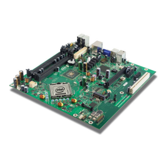
Figure 1 shows overview of the major features present on the development kit board. Refer to next page for system block diagram of the development kit’s motherboard.
|
Intel® CoreTM 2 Duo Processor and Intel ® Q35 Express Chipset Development Kit |
|
|
User’s Manual |
October 2007 |
|
10 |
Order Number: 318476001US |

Development Kit Hardware Features—Intel Core 2 Duo Processor and Intel Q35 Express Chipset
|
Figure 1. |
Board Features |
|||||||||||||||||||||||
|
Reset button |
||||||||||||||||||||||||
|
PCI Slot |
||||||||||||||||||||||||
|
PCI Express |
||||||||||||||||||||||||
|
x1 Slot |
||||||||||||||||||||||||
|
Power Button |
||||||||||||||||||||||||
|
SPI EEPROM |
||||||||||||||||||||||||
|
(Secondary) |
||||||||||||||||||||||||
|
Port 80 LED Display |
||||||||||||||||||||||||
|
SPI EEPROM |
||||||||||||||||||||||||
|
(Primary) |
||||||||||||||||||||||||
|
PCI Express |
||||||||||||||||||||||||
|
x16 Graphics |
||||||||||||||||||||||||
|
Slot |
||||||||||||||||||||||||
|
LGA775 Processor |
||||||||||||||||||||||||
|
Socket |
||||||||||||||||||||||||
|
Intel® I/O |
||||||||||||||||||||||||
|
Controller Hub |
||||||||||||||||||||||||
|
(ICH) |
||||||||||||||||||||||||
|
SATA Port |
||||||||||||||||||||||||
|
Intel® Q35 Memory |
||||||||||||||||||||||||
|
Controller Hub (MCH) |
||||||||||||||||||||||||
|
2×2 Standard |
||||||||||||||||||||||||
|
Power Supply |
||||||||||||||||||||||||
|
2×12 |
||||||||||||||||||||||||
|
Standard |
||||||||||||||||||||||||
|
Power Supply |
||||||||||||||||||||||||
|
2-DIMM per channel DDR2 |
2-DIMM per channel DDR2 |
|||||||||||||||||||||||
|
667/800 (Channel-B) |
667/800 (Channel-A) |
|||||||||||||||||||||||
2.2System Block Diagram
This section will document the common features that are applicable to the Intel® CoreTM 2 Duo Processor and Intel ® Q35 Express Chipset Development Kit. Figure 2 shows a simple block diagram of the development kit.
|
Intel® CoreTM 2 Duo Processor and Intel ® Q35 Express Chipset Development Kit |
|
|
October 2007 |
User’s Manual |
|
Order Number: 318476001US |
11 |
 Loading…
|
|
Related Devices:
|
Types of Manuals:
The main types of Intel Core 2 Duo Processor instructions:
- User guide — rules of useing and characteristics
- Service manual — repair, diagnostics, maintenance
- Operation manual — description of the main functions of equipment
Computer Hardware, Processor Instructions by Intel:
-
HPE StoreEver 1/8 G2
HPE StoreEver 1/8 G2 Tape AutoloaderGetting Started Guide*Q6Q67-00001*Part Number: Q6Q67-00001Published: December 2017Edition: 8AbstractThis guide provides information necessary to install the 1/8 G2 Tape Autoloader. This guide isintended for system administrators and other users who need physical knowledge of theautol …
StoreEver 1/8 G2 Computer Hardware, 24
-
Dell PowerEdge 2800
www.dell.com | support.dell.comDell™ PowerEdge™ SystemsProcessor UpgradeInstallation Guide处理器升级安装指南Guide d’installation pour la miseà niveau du processeurAnleitung zum Prozessor-Upgradeプロセッサアップグレードインストールガイド프로세서 업그레이드설치 안내서 …
PowerEdge 2800 Server, 56
-
Siemens SIMATIC NET
SCALANCE XC100-4OBR ___________________ ___________________ ___________________ ___________________ ___________________ ___________________ ___________________ ___________________ SIMATIC NET Network components SCALANCE XC100-4OBR Operating Instructions 10/2013 C79000-G8976-C297-02 Introduction 1 Safety notes 2 …
SIMATIC NET Network Hardware, 54
-
SightLine 3000-OEM
© SightLine Applications, Inc. EAN- Startup Guide 3000-OEM 2020-11-03 Exports: Export Summary Sheet EULA: End User License Agreement Web: sightlineapplications.com Sales: [email protected] Support: [email protected] Phone: +1 (541) 716-5137 1 Overview ……………………… …
3000-OEM Media Converter, 13
-
Eaton COOPER POWER SERIES
GeneralEaton’s Cooper Power™ series 600 A, 35 kV Class PUSH-OP™ bushing adapter is a factory as sembled LRTP and extender with a stainless steel shroud and tin-plated copper probe. It meets all the requirements of IEEE Std 386™-2006 standard – Separable Connector Sys tems.The PUSH-OP bushing adapter has a …
COOPER POWER SERIES Cables and connectors, 2
-
Renesas H8/38024
Revision Date: Aug 27, 20048H8/38024, H8/38024S,H8/38024F-ZTAT, H8/38124 GroupHardware ManualRenesas 8-Bit Single-Chip MicrocomputerH8 Family/H8/300L Super Low Power SeriesRev. 6.00REJ09B0042-0600OThe revision list can be viewed directly byclicking the title page.The revision list summarizes the locations ofrevisions a …
H8/38024 Computer Hardware, 661
-
Data Aire DAP III
Data Aire DAPTM III BACnet Integration Instructions Data Aire, Inc. 230 West BlueRidge Avenue Orange, California 92865 800-347-2473 714-921-6000 www.dataaire.com Engineering Document Number 600-000-460 April 2009 Revision 2.0 …
DAP III Control Panel, 13
- Manuals
- Brands
- Intel Manuals
- Computer Hardware
- Core 2 Duo Processor
Manuals and User Guides for Intel Core 2 Duo Processor. We have 8 Intel Core 2 Duo Processor manuals available for free PDF download: Datasheet, User Manual, Design Manual, Installation Instructions Manual
Используемая вами версия браузера не рекомендована для просмотра этого сайта.
Установите последнюю версию браузера, перейдя по одной из следующих ссылок.
- Safari
- Chrome
- Edge
- Firefox
-
Поиск примеров
-
Вы можете использовать несколько способов поиска продукции в нашем каталоге процессоров, наборов микросхем, комплектов, твердотельных накопителей, серверной и другой продукции.
-
Название торговой марки:
Core i7 -
Номер продукции:
i7-12700KF -
Код заказа:
CM8071504553829 -
Код спецификации:
SRL4P -
Кодовое название:
Alder Lake
6 МБ кэш-памяти, тактовая частота 3,00 ГГц, частота системной шины 1333 МГц
Спецификации
Сравнение продукции Intel®
-
Коллекция продукции
Устаревшие процессоры Intel® Core™
-
Кодовое название
Продукция с прежним кодовым названием Wolfdale
-
Вертикальный сегмент
Desktop -
Номер процессора
E8400 -
Литография
45 nm -
Условия использования
PC/Client/Tablet
Спецификации корпуса
-
Поддерживаемые разъемы
LGA775 -
TCASE
72.4°C -
Размер корпуса
37.5mm x 37.5mm -
Размер ядра процессора
107 mm2 -
Кол-во транзисторов в ядре процессора
410 million
Усовершенствованные технологии
-
Технология Intel® Turbo Boost ‡
Нет -
Технология Intel® Hyper-Threading ‡
Нет -
Технология виртуализации Intel® (VT-x) ‡
Да -
Технология виртуализации Intel® для направленного ввода/вывода (VT-d) ‡
Да -
Архитектура Intel® 64 ‡
Да -
Набор команд
64-bit -
Состояния простоя
Да -
Enhanced Intel SpeedStep® Technology (Усовершенствованная технология Intel SpeedStep®)
Да -
Технология Intel® Demand Based Switching
Нет -
Технологии термоконтроля
Да
Заказ и соблюдение требований
Продукция, снятая с производства
Intel® Core™2 Duo Processor E8400 (6M Cache, 3.00 GHz, 1333 MHz FSB) LGA775, Tray
-
MM#
893557 -
Код спецификации
SLAPL -
Код заказа
EU80570PJ0806M -
Средство доставки
TRAY -
Степпинг
C0 -
Идентификаторы MDDS
708949
Boxed Intel® Core™2 Duo Processor E8400 (6M Cache, 3.00 GHz, 1333 MHz FSB) LGA775
-
MM#
894369 -
Код спецификации
SLAPL -
Код заказа
BX80570E8400A -
Средство доставки
BOX -
Степпинг
C0 -
Идентификаторы MDDS
707707
Boxed Intel® Core™2 Duo Processor E8400 (6M Cache, 3.00 GHz, 1333 MHz FSB) LGA775
-
MM#
895696 -
Код заказа
BX80570E8400 -
Средство доставки
BOX -
Степпинг
C0 -
Идентификаторы MDDS
707707
Boxed Intel® Core™2 Duo Processor E8400 (6M Cache, 3.00 GHz, 1333 MHz FSB) LGA775
-
MM#
895733 -
Код спецификации
SLAPL -
Код заказа
BX80570E8400 -
Средство доставки
BOX -
Степпинг
C0 -
Идентификаторы MDDS
707707
Intel® Core™2 Duo Processor E8400 (6M Cache, 3.00 GHz, 1333 MHz FSB) LGA775, Tray
-
MM#
898841 -
Код спецификации
SLB9J -
Код заказа
AT80570PJ0806M -
Средство доставки
TRAY -
Степпинг
E0 -
Идентификаторы MDDS
708949
Boxed Intel® Core™2 Duo Processor E8400 (6M Cache, 3.00 GHz, 1333 MHz FSB) LGA775
-
MM#
899035 -
Код спецификации
SLB9J -
Код заказа
BX80570E8400 -
Средство доставки
BOX -
Степпинг
E0 -
Идентификаторы MDDS
707707
Информация о соблюдении торгового законодательства
-
ECCN
3A991.A.1 -
CCATS
NA -
US HTS
8542310001
Информация о PCN
Совместимая продукция
Поиск совместимых системных плат для настольных ПК
Поиск плат, совместимых с Процессор Intel® Core™2 Duo E8400 в инструменте проверки совместимости для настольных ПК
Семейство серверных плат Intel® S3200SH
Семейство серверных плат Intel® X38ML
Семейство серверных систем Intel® SR1000SH
Наборы микросхем Intel® серии 4
Наборы микросхем Intel® серии 3
Наборы микросхем Intel® серии 3000
Драйверы и ПО
Описание
Тип
Подробнее
ОС
Версия
Дата
Все
Подробно
Скачать
Просмотреть параметры загрузки
Поиск не дал результатов для запроса
Y
/apps/intel/arksuite/template/arkProductPageTemplate
Новейшие драйверы и ПО
Не найдено результатов для этого продукта.
Доступные загружаемые материалы:
Имя
Поддержка
Литография
Литография указывает на полупроводниковую технологию, используемую для производства интегрированных наборов микросхем и отчет показывается в нанометре (нм), что указывает на размер функций, встроенных в полупроводник.
Условия использования
Условия использования — это факторы окружающей среды и эксплуатационные характеристики, соответствующие должному использованию системы.
Для получения информации об условиях использования, относящихся к конкретному SKU, см. отчет PRQ.
Текущую информацию об условиях использования см. в материалах Intel UC (сайт соглашения о неразглашении информации)*.
Количество ядер
Количество ядер — это термин аппаратного обеспечения, описывающий число независимых центральных модулей обработки в одном вычислительном компоненте (кристалл).
Базовая тактовая частота процессора
Базовая частота процессора — это скорость открытия/закрытия транзисторов процессора. Базовая частота процессора является рабочей точкой, где задается расчетная мощность (TDP). Частота измеряется в гигагерцах (ГГц) или миллиардах вычислительных циклов в секунду.
Кэш-память
Кэш-память процессора — это область быстродействующей памяти, расположенная в процессоре. Интеллектуальная кэш-память Intel® Smart Cache указывает на архитектуру, которая позволяет всем ядрам совместно динамически использовать доступ к кэшу последнего уровня.
Частота системной шины
Шина — это подсистема, передающая данные между компонентами компьютера или между компьютерами. В качестве примера можно назвать системную шину (FSB), по которой происходит обмен данными между процессором и блоком контроллеров памяти; интерфейс DMI, который представляет собой соединение «точка-точка» между встроенным контроллером памяти Intel и блоком контроллеров ввода/вывода Intel на системной плате; и интерфейс Quick Path Interconnect (QPI), соединяющий процессор и интегрированный контроллер памяти.
Четность системной шины
Четность системной шины обеспечивает возможность проверки ошибок в данных, отправленных в FSB (системная шина).
Расчетная мощность
Расчетная тепловая мощность (TDP) указывает на среднее значение производительности в ваттах, когда мощность процессора рассеивается (при работе с базовой частотой, когда все ядра задействованы) в условиях сложной нагрузки, определенной Intel. Ознакомьтесь с требованиями к системам терморегуляции, представленными в техническом описании.
Диапазон напряжения VID
Диапазон напряжения VID является индикатором значений минимального и максимального напряжения, на которых процессор должен работать. Процессор обеспечивает взаимодействие VID с VRM (Voltage Regulator Module), что, в свою очередь обеспечивает, правильный уровень напряжения для процессора.
Дата выпуска
Дата выпуска продукта.
Доступные варианты для встраиваемых систем
Доступные варианты для встраиваемых систем указывают на продукты, обеспечивающие продленную возможность приобретения для интеллектуальных систем и встроенных решений. Спецификация продукции и условия использования представлены в отчете Production Release Qualification (PRQ). Обратитесь к представителю Intel для получения подробной информации.
Поддерживаемые разъемы
Разъемом называется компонент, которые обеспечивает механические и электрические соединения между процессором и материнской платой.
TCASE
Критическая температура — это максимальная температура, допустимая в интегрированном теплораспределителе (IHS) процессора.
Технология Intel® Turbo Boost ‡
Технология Intel® Turbo Boost динамически увеличивает частоту процессора до необходимого уровня, используя разницу между номинальным и максимальным значениями параметров температуры и энергопотребления, что позволяет увеличить эффективность энергопотребления или при необходимости «разогнать» процессор.
Технология Intel® Hyper-Threading ‡
Intel® Hyper-Threading Technology (Intel® HT Technology) обеспечивает два потока обработки для каждого физического ядра. Многопоточные приложения могут выполнять больше задач параллельно, что значительно ускоряет выполнение работы.
Технология виртуализации Intel® (VT-x) ‡
Технология Intel® Virtualization для направленного ввода/вывода (VT-x) позволяет одной аппаратной платформе функционировать в качестве нескольких «виртуальных» платформ. Технология улучшает возможности управления, снижая время простоев и поддерживая продуктивность работы за счет выделения отдельных разделов для вычислительных операций.
Технология виртуализации Intel® для направленного ввода/вывода (VT-d) ‡
Технология Intel® Virtualization Technology для направленного ввода/вывода дополняет поддержку виртуализации в процессорах на базе архитектуры IA-32 (VT-x) и в процессорах Itanium® (VT-i) функциями виртуализации устройств ввода/вывода. Технология Intel® Virtualization для направленного ввода/вывода помогает пользователям увеличить безопасность и надежность систем, а также повысить производительность устройств ввода/вывода в виртуальных средах.
Архитектура Intel® 64 ‡
Архитектура Intel® 64 в сочетании с соответствующим программным обеспечением поддерживает работу 64-разрядных приложений на серверах, рабочих станциях, настольных ПК и ноутбуках.¹ Архитектура Intel® 64 обеспечивает повышение производительности, за счет чего вычислительные системы могут использовать более 4 ГБ виртуальной и физической памяти.
Набор команд
Набор команд содержит базовые команды и инструкции, которые микропроцессор понимает и может выполнять. Показанное значение указывает, с каким набором команд Intel совместим данный процессор.
Состояния простоя
Режим состояния простоя (или C-состояния) используется для энергосбережения, когда процессор бездействует. C0 означает рабочее состояние, то есть ЦПУ в данный момент выполняет полезную работу. C1 — это первое состояние бездействия, С2 — второе состояние бездействия и т.д. Чем выше численный показатель С-состояния, тем больше действий по энергосбережению выполняет программа.
Enhanced Intel SpeedStep® Technology (Усовершенствованная технология Intel SpeedStep®)
Усовершенствованная технология Intel SpeedStep® позволяет обеспечить высокую производительность, а также соответствие требованиям мобильных систем к энергосбережению. Стандартная технология Intel SpeedStep® позволяет переключать уровень напряжения и частоты в зависимости от нагрузки на процессор. Усовершенствованная технология Intel SpeedStep® построена на той же архитектуре и использует такие стратегии разработки, как разделение изменений напряжения и частоты, а также распределение и восстановление тактового сигнала.
Технология Intel® Demand Based Switching
Intel® Demand Based Switching — это технология управления питанием, в которой прикладное напряжение и тактовая частота микропроцессора удерживаются на минимальном необходимом уровне, пока не потребуется увеличение вычислительной мощности. Эта технология была представлена на серверном рынке под названием Intel SpeedStep®.
Технологии термоконтроля
Технологии термоконтроля защищают корпус процессора и систему от сбоя в результате перегрева с помощью нескольких функций управления температурным режимом. Внутрикристаллический цифровой термодатчик температуры (Digital Thermal Sensor — DTS) определяет температуру ядра, а функции управления температурным режимом при необходимости снижают энергопотребление корпусом процессора, тем самым уменьшая температуру, для обеспечения работы в пределах нормальных эксплуатационных характеристик.
Новые команды Intel® AES
Команды Intel® AES-NI (Intel® AES New Instructions) представляют собой набор команд, позволяющий быстро и безопасно обеспечить шифрование и расшифровку данных. Команды AES-NI могут применяться для решения широкого спектра криптографических задач, например, в приложениях, обеспечивающих групповое шифрование, расшифровку, аутентификацию, генерацию случайных чисел и аутентифицированное шифрование.
Технология Intel® Trusted Execution ‡
Технология Intel® Trusted Execution расширяет возможности безопасного исполнения команд посредством аппаратного расширения возможностей процессоров и наборов микросхем Intel®. Эта технология обеспечивает для платформ цифрового офиса такие функции защиты, как измеряемый запуск приложений и защищенное выполнение команд. Это достигается за счет создания среды, где приложения выполняются изолированно от других приложений системы.
Функция Бит отмены выполнения ‡
Бит отмены выполнения — это аппаратная функция безопасности, которая позволяет уменьшить уязвимость к вирусам и вредоносному коду, а также предотвратить выполнение вредоносного ПО и его распространение на сервере или в сети.
Процессор в оптовой упаковке
Intel поставляет эти процессоры OEM-производителям, которые предустанавливают их в свои системы. Intel называет такие процессоры процессорами в оптовой упаковке или OEM-процессорами. Для таких процессоров Intel не предоставляет непосредственное гарантийное обслуживание. За гарантийной поддержкой обращайтесь к OEM-производителю или реселлеру.
В чем разница между процессорами в штучной и оптовой упаковке?
Процессор в штучной упаковке
Авторизованные дистрибьюторы Intel продают процессоры Intel в упаковках Intel с четким обозначением. Эти процессоры называются процессорами в штучной упаковке. На них, как правило, распространяется трехлетняя гарантия.
В чем разница между процессорами в штучной и оптовой упаковке?
Процессор в оптовой упаковке
Intel поставляет эти процессоры OEM-производителям, которые предустанавливают их в свои системы. Intel называет такие процессоры процессорами в оптовой упаковке или OEM-процессорами. Для таких процессоров Intel не предоставляет непосредственное гарантийное обслуживание. За гарантийной поддержкой обращайтесь к OEM-производителю или реселлеру.
В чем разница между процессорами в штучной и оптовой упаковке?
Процессор в штучной упаковке
Авторизованные дистрибьюторы Intel продают процессоры Intel в упаковках Intel с четким обозначением. Эти процессоры называются процессорами в штучной упаковке. На них, как правило, распространяется трехлетняя гарантия.
В чем разница между процессорами в штучной и оптовой упаковке?
Вам нужна дополнительная помощь?
Оставьте отзыв
Оставьте отзыв
Наша цель — сделать семейство инструментов ARK максимально полезным для вас ресурсом. Оставьте свои вопросы, комментарии или предложения здесь. Вы получите ответ в течение 2 рабочих дней.
Ваши комментарии отправлены. Спасибо за ваш отзыв.
Предоставленная вами персональная информация будет использована только для ответа на этот запрос. Ваше имя и адрес электронной почты не будут добавлены ни в какие списки рассылок, и вы не будете получать электронные сообщения от корпорации Intel без вашего запроса. Нажимая кнопку «Отправить», вы подтверждаете принятие Условий использования Intel и понимание Политики конфиденциальности Intel.
Вся информация, приведенная в данном документе, может быть изменена в любое время без предварительного уведомления. Корпорация Intel сохраняет за собой право вносить изменения в цикл производства, спецификации и описания продукции в любое время без уведомления. Информация в данном документе предоставлена «как есть». Корпорация Intel не делает никаких заявлений и гарантий в отношении точности данной информации, а также в отношении характеристик, доступности, функциональных возможностей или совместимости перечисленной продукции. За дополнительной информацией о конкретных продуктах или системах обратитесь к поставщику таких систем.
Классификации Intel приведены исключительно в информационных целях и состоят из номеров классификации экспортного контроля (ECCN) и номеров Гармонизированных таможенных тарифов США (HTS). Классификации Intel должны использоваться без отсылки на корпорацию Intel и не должны трактоваться как заявления или гарантии в отношении правильности ECCN или HTS. В качестве импортера и/или экспортера ваша компания несет ответственность за определение правильной классификации вашей транзакции.
Формальные определения свойств и характеристик продукции представлены в техническом описании.
‡ Эта функция может присутствовать не во всех вычислительных системах. Свяжитесь с поставщиком, чтобы получить информацию о поддержке этой функции вашей системой или уточнить спецификацию системы (материнской платы, процессора, набора микросхем, источника питания, жестких дисков, графического контроллера, памяти, BIOS, драйверов, монитора виртуальных машин (VMM), платформенного ПО и/или операционной системы) для проверки совместимости с этой функцией. Функциональные возможности, производительность и другие преимущества этой функции могут в значительной степени зависеть от конфигурации системы.
Некоторые продукты могут поддерживать новые наборы инструкций AES с обновлением конфигурации процессоров, в частности, i7-2630QM/i7-2635QM, i7-2670QM/i7-2675QM, i5-2430M/i5-2435M, i5-2410M/i5-2415M. Свяжитесь с OEM-поставщиком для получения BIOS, включающего последнее обновление конфигурации процессора.
Максимальная тактовая частота с технологией Turbo Boost — это максимальная тактовая частота одноядерного процессора, которую можно достичь с помощью технологии Intel® Turbo Boost. Более подробную информацию можно найти по адресу https://www.intel.com/content/www/ru/ru/architecture-and-technology/turbo-boost/turbo-boost-technology.html.
Номера процессоров Intel® не служат мерой измерения производительности. Номера процессоров указывают на различия характеристик процессоров в пределах семейства, а не на различия между семействами процессоров. Дополнительную информацию смотрите на сайте https://www.intel.com/content/www/ru/ru/processors/processor-numbers.html.
Для процессоров с поддержкой 64-разрядных архитектур Intel® требуется поддержка технологии Intel® 64 в BIOS.
Анонсированные артикулы (SKUs) на данный момент недоступны. Обратитесь к графе «Дата выпуска» для получения информации о доступности продукции на рынке.
Расчетная мощность системы и максимальная расчетная мощность рассчитаны для максимально возможных показателей. Реальная расчетная мощность может быть ниже, если используются не все каналы ввода/вывода набора микросхем.
Для получения дополнительной информации, в том числе о процессорах, поддерживающих технологию Intel® HT, посетите сайт https://www.intel.com/content/www/ru/ru/architecture-and-technology/hyper-threading/hyper-threading-technology.html?wapkw=hyper+threading.
-
Contents
-
Table of Contents
-
Bookmarks
Quick Links
®
TM
Intel
Core
2 Duo Processor and
®
Intel
Q35 Express Chipset
Development Kit
User’s Manual
October 2007
Order Number: 318476-001US
Related Manuals for Intel Core 2 Duo
Summary of Contents for Intel Core 2 Duo
-
Page 1
® Intel Core 2 Duo Processor and ® Intel Q35 Express Chipset Development Kit User’s Manual October 2007 Order Number: 318476-001US… -
Page 2
Contact your local Intel sales office or your distributor to obtain the latest specifications and before placing your product order. Copies of documents which have an order number and are referenced in this document, or other Intel literature may be obtained by calling 1-800-548-4725 or by visiting Intel’s website at http://www.intel.com. -
Page 3: Table Of Contents
Contents—Intel Core 2 Duo Processor and Intel Q35 Express Chipset Contents About This Manual … 6 Content Overview… 6 Text Conventions … 6 Glossary of Terms and Acronyms…7 Support Options … 8 1.4.1 Electronic Support Systems … 8 1.4.2 Additional Technical Support …8 Product Literature …
-
Page 4
1394a Header …23 ® Intel Core 2 Duo Processor and Intel User’s Manual Intel Core 2 Duo Processor and Intel Q35 Express Chipset—Contents ® Q35 Express Chipset Development Kit Board ® Q35 Express Chipset Development Kit October 2007 Order Number: 318476-001US… -
Page 5: Revision History
Revision History—Intel Core 2 Duo Processor and Intel Q35 Express Chipset Revision History Date Revision Description October 2007 Initial release ® ® Intel Core 2 Duo Processor and Intel Q35 Express Chipset Development Kit October 2007 User’s Manual Order Number: 318476-001US…
-
Page 6: About This Manual
® Intel Core 2 Duo Processor and Intel User’s Manual Intel Core 2 Duo Processor and Intel Q35 Express Chipset—About This Manual ® Q35 Express Chipset Development Kit ® The pound symbol (#) appended to a signal name indicates that the signal is active low.
-
Page 7: Glossary Of Terms And Acronyms
Definition (Sheet 1 of 2) Term Advanced Digital Display Card – 2 for an Intel Graphics Controller that supports ADD2+ cards. It plugs into a x16 PCI Express* connector but uses the multiplexed SDVO interface. The card adds Video In ADD2 Card capabilities to platform.
-
Page 8: Support Options
Definition (Sheet 2 of 2) Term Advanced Digital Display Card – 2 for an Intel Graphics Controller that supports ADD2+ cards. It plugs into a x16 PCI Express* connector but uses the multiplexed SDVO interface. The card adds Video In ADD2 Card capabilities to platform.
-
Page 9: Intel Literature Centers
About This Manual—Intel Core 2 Duo Processor and Intel Q35 Express Chipset Table 2. Intel Literature Centers Location U.S. and Canada U.S. (from overseas) Europe (U.K.) Germany France Japan (fax only) October 2007 Order Number: 318476001US Telephone Number 1-800-548-4725 708-296-9333…
-
Page 10: Development Kit Hardware Features
Intel Core 2 Duo Processor and Intel Q35 Express Chipset—Development Kit Hardware Features Development Kit Hardware Features This chapter describes the features of the Intel® Q35 Development Kit. These recommendations would largely apply to other designs incorporating Intel® Q35 chipset. This documentation should be used in conjunction with the datasheets, specification updates and platform design guides for the Intel®…
-
Page 11: System Block Diagram
Development Kit Hardware Features—Intel Core 2 Duo Processor and Intel Q35 Express Chipset Figure 1. Board Features PCI Slot PCI Express x1 Slot SPI EEPROM (Secondary) SPI EEPROM (Primary) PCI Express x16 Graphics Slot Intel® I/O Controller Hub (ICH) SATA Port…
-
Page 12: Development Kit Inventory Checklists
Intel Core 2 Duo Processor and Intel Q35 Express Chipset—Development Kit Hardware Features Figure 2. Intel® Q35 Express Chipset Development Kit block diagram Development Kit Inventory Checklists This section describes major hardware items which should be available on this development kit.
-
Page 13: Development Kit Board Specification
Development Kit Hardware Features—Intel Core 2 Duo Processor and Intel Q35 Express Chipset Table 4. Development Kit Board Specification 1 PCI Express x16, 2 PCIe x1, 1 PCI expansion slots 1394a • 1 front panel headers for support of 1 port •…
-
Page 14: Processor Support
• Intel Pentium ® • Intel Celeron Refer to this link for other processors which is also supported by Intel® Q35 Express Chipset. http://developer.intel.com/products/chipsets/Q35_Q33/index.htm System Memory The Intel® Q35 Express Chipset supports two types of memory organization. These are interleaved mode and asymmetric mode. The Q35 supports: Listed here are the summary of the system memory supported.
-
Page 15: Dual Channel (Interleaved) Mode Configurations
Development Kit Hardware Features—Intel Core 2 Duo Processor and Intel Q35 Express Chipset • Non-ECC DDR2 (667/800) • 512Mb, 1Gb and 2Gb technology • 4 DIMMs, 4GB maximum per channel, 8GB total memory • Dual channel (Interleaved) mode. This mode offers the highest throughput for real world applications.
-
Page 16: Dual Channel (Interleaved) Mode Configuration With 2X Dimms
Intel Core 2 Duo Processor and Intel Q35 Express Chipset—Development Kit Hardware Features Figure 4. Dual Channel (Interleaved) Mode Configuration with 2x DIMMs Figure 5 shows a dual channel configuration using 3 DIMMs. In this example, the combined capacity of the two DIMMs in Channel A equal the capacity of the single DIMM in the DIMM 0 socket of Channel B.
-
Page 17: Single Channel (Asymmetric) Mode Configurations
Development Kit Hardware Features—Intel Core 2 Duo Processor and Intel Q35 Express Chipset Figure 6. Dual Channel (Interleaved) Mode Configuration with 4x DIMMs 2.5.2 Single Channel (Asymmetric) Mode Configurations Figure 7 shows a single channel configuration using 1x DIMM. In this example, only the DIMM 0 socket of Channel A is populated.
-
Page 18: Back-Panel Connectors
Intel Core 2 Duo Processor and Intel Q35 Express Chipset—Development Kit Hardware Features Figure 8. Single Channel (Asymmetric) Mode Configuration with 3x DIMMs Back-Panel Connectors Figure 9 shows back-panel connectors for the development kit. Figure 9. Back-panel Connectors 1394a Port…
-
Page 19: Lan Connector With Integrated Leds
Development Kit Hardware Features—Intel Core 2 Duo Processor and Intel Q35 Express Chipset Center/Subwoofer Speaker Out Jack (Orange) This audio jack is used to connect to center/subwoofer speakers in a 5.1 and 7.1- channel audio configuration. Rear Speaker Out (Black) This audio jack is used to connect to rear speakers in a 5.1 and 7.1-channel audio…
-
Page 20: Debug Features
Intel Core 2 Duo Processor and Intel Q35 Express Chipset—Development Kit Hardware Features Debug Features 2.7.1 Extended Debug Probe (XDP) The reference board provides a JTAG-compliant test access port (TAP) for attachment of an XDP connector. The XDP connector and associated circuitry enable the use of the ITP for the particular processor to interrupt the boot sequence and view processor status.
-
Page 21: Voltage Reference
Development Kit Hardware Features—Intel Core 2 Duo Processor and Intel Q35 Express Chipset 2.7.4 Voltage Reference Table 9 for details of the expected voltage levels for each voltage rail on the CRB. Table 9. Voltage Reference detail Voltage Rail VCC3…
-
Page 22: Jumper Functions
Intel Core 2 Duo Processor and Intel Q35 Express Chipset—Development Kit Hardware Features 2.8.1 Jumper Functions Table 10 provides a list of the setting definitions for the Intel ® and Intel Q35 Express Chipset Development Kit. ® Table 10. Intel…
-
Page 23: Spi Removal / Installation Technique
Development Kit Hardware Features—Intel Core 2 Duo Processor and Intel Q35 Express Chipset Figure 13. Location for 1394a Header and USB Front Panel U1FW (USB Front Panel) Table 12. 1394a Header Pin Number SPI Removal / Installation Technique When removing or installing the SPI device, care must be taken to avoid damage to the SPI socket.
-
Page 24: Spi Device Removal
Intel Core 2 Duo Processor and Intel Q35 Express Chipset—Development Kit Hardware Features 2.9.1 SPI Device Removal To remove the SPI device from the socket, use a tweezer tip to gently pry one leg of the cap away from the socket. There is a small latch on the bottom of the leg of the cap.
-
Page 25: Spi Device Installation
Development Kit Hardware Features—Intel Core 2 Duo Processor and Intel Q35 Express Chipset Figure 15. SPI Device Installation 1. Place the fresh IC into the socket. Match pin 1. on the IC to pin 1 on the socket. 3. Lock the cover with the hook.
-
Page 26: Setting Up And Configuring The Development Kit
Intel Core 2 Duo Processor and Intel Q35 Express Chipset—Setting Up and Configuring the Setting Up and Configuring the Development Kit This chapter discusses basic board set up and operation. Please refer to the board layout, jumper setting location and the component reference designator.
-
Page 27: Mounting Hole Locations
Setting Up and Configuring the Development Kit—Intel Core 2 Duo Processor and Intel Q35 Express Chipset environment. Since the board is not in a protective chassis, the user is required to observe extra precautions when handling and operating the system.
-
Page 28: Btx Heatsink Setup With Srm
Intel Core 2 Duo Processor and Intel Q35 Express Chipset—Setting Up and Configuring the Figure 18. Mounting the Standoff for BTX Heatsink BTX Heatsink Setup with SRM This section describes BTX casing which uses “Support and Retention Module (SRM)” as…
-
Page 29: Btx Board Alignment On Srm
Setting Up and Configuring the Development Kit—Intel Core 2 Duo Processor and Intel Q35 Express Chipset 1. Place the uBTX board on the Support and Retention Module (SRM) so that the holes A, B, C and D on the PCB line up with the corresponding locations on the SRM (see Figure 19).
-
Page 30: Board Setup And Configuration Before Boot
Intel Core 2 Duo Processor and Intel Q35 Express Chipset—Setting Up and Configuring the Figure 22. Tightening Heatsink on the SRM and Board Board Setup and Configuration before Boot Follow the steps below to operate the board. Warning: Before starting, ensure the power supply is not connected to the board.
-
Page 31: Cpu Fan Location
Setting Up and Configuring the Development Kit—Intel Core 2 Duo Processor and Intel Q35 Express Chipset 2. Set jumpers to default positions. Refer to 3. Install the processor and ensure the 4-pin CPU fan power connector is installed on header shown in Figure 23.
-
Page 32: Post Codes Definitions
Intel Core 2 Duo Processor and Intel Q35 Express Chipset—Setting Up and Configuring the Figure 24. 2×12 Standard power supply and 2×2 power supply Post Codes Definitions The CRB BIOS writes progress and error codes to Port 80 during POST. These codes are defined below.
-
Page 33
Setting Up and Configuring the Development Kit—Intel Core 2 Duo Processor and Intel Q35 Express Chipset E1-E8 EC-EE Boot Block Recovery Code Checkpoints Runtime POST Code Checkpoints October 2007 Order Number: 318476001US Restore CPUID value to register. Bootblock runtime module transferred to system memory. -
Page 34
Intel Core 2 Duo Processor and Intel Q35 Express Chipset—Setting Up and Configuring the ® Intel Core 2 Duo Processor and Intel User’s Manual Initialize CPU. The BAT test performed on KBC. Auto detection of KB and MS. Early CPU Init Start. Disable cache and init local APIC. -
Page 35
Setting Up and Configuring the Development Kit—Intel Core 2 Duo Processor and Intel Q35 Express Chipset 61-70 October 2007 Order Number: 318476001US Initialize NUM-LOCK status and program typematic rate. Initialize INT-13 and prepare for IPL detection. Initialize IPL devices controlled by BIOS and option ROMs. -
Page 36: User’s Manual October
Intel Core 2 Duo Processor and Intel Q35 Express Chipset—Setting Up and Configuring the Development Kit ® ® Intel Core 2 Duo Processor and Intel Q35 Express Chipset Development Kit User’s Manual October 2007 Order Number: 318476001US…
Краткое содержание страницы № 1
® TM
Intel Core 2 Duo Processor and
®
Intel Q35 Express Chipset
Development Kit
User’s Manual
October 2007
Order Number: 318476-001US
Краткое содержание страницы № 2
Legal Lines and Disclaimers INFORMATION IN THIS DOCUMENT IS PROVIDED IN CONNECTION WITH INTEL® PRODUCTS. NO LICENSE, EXPRESS OR IMPLIED, BY ESTOPPEL OR OTHERWISE, TO ANY INTELLECTUAL PROPERTY RIGHTS IS GRANTED BY THIS DOCUMENT. EXCEPT AS PROVIDED IN INTEL’S TERMS AND CONDITIONS OF SALE FOR SUCH PRODUCTS, INTEL ASSUMES NO LIABILITY WHATSOEVER, AND INTEL DISCLAIMS ANY EXPRESS OR IMPLIED WARRANTY, RELATING TO SALE AND/OR USE OF INTEL PRODUCTS INCLUDING LIABILITY OR WARRANTIES RELATING TO FITNESS
Краткое содержание страницы № 3
Contents—Intel Core 2 Duo Processor and Intel Q35 Express Chipset Contents 1.0 About This Manual………………………………………………………………………………………..6 1.1 Content Overview……………………………………………………………………………………6 1.2 Text Conventions ……………………………………………………………………………………6 1.3 Glossary of Terms and Acronyms…………………………
Краткое содержание страницы № 4
Intel Core 2 Duo Processor and Intel Q35 Express Chipset—Contents 6 Dual Channel (Interleaved) Mode Configuration with 4x DIMMs…………………………………17 7 Single Channel (Asymmetric) Mode Configuration with 1x DIMM ……………………………….17 8 Single Channel (Asymmetric) Mode Configuration with 3x DIMMs………………………………18 9 Back-panel Connectors………………………………………………………………………………….18 10 LAN C
Краткое содержание страницы № 5
Revision History—Intel Core 2 Duo Processor and Intel Q35 Express Chipset Revision History Date Revision Description October 2007 001 Initial release ® TM ® Intel Core 2 Duo Processor and Intel Q35 Express Chipset Development Kit October 2007 User’s Manual Order Number: 318476-001US 5
Краткое содержание страницы № 6
Intel Core 2 Duo Processor and Intel Q35 Express Chipset—About This Manual 1.0 About This Manual ® This user’s manual describes the use of the Intel Q35 Express Chipset Development Kit. This manual has been written for OEMs, system evaluators, and embedded system developers. All jumpers, headers, LED functions, and their locations on the board, along with subsystem features and POST codes, are defined in this document. ® For the latest information about the Intel Q35 Express Chipset Developme
Краткое содержание страницы № 7
About This Manual—Intel Core 2 Duo Processor and Intel Q35 Express Chipset is shown as 0FFH.) Decimal and binary numbers are represented by their customary notations (That is, 255 is a decimal number and 1111 1111 is a binary number). In some cases, the letter B is added for clarity. Units of Measure The following abbreviations are used to represent units of measure: GByte gigabytes KByte kilobytes MByte megabytes MHz megahertz W watts V volts Signal Names Signal names are shown in uppercase
Краткое содержание страницы № 8
Intel Core 2 Duo Processor and Intel Q35 Express Chipset—About This Manual Table 1. Definition (Sheet 2 of 2) Term Description nd Advanced Digital Display Card – 2 Generation. This card provides digital display options for an Intel Graphics Controller that supports ADD2+ cards. It plugs into a x16 PCI Express* connector but uses the multiplexed SDVO interface. The card adds Video In ADD2 Card capabilities to platform. This Advanced Digital Display Card will not work with an Intel Graphics C
Краткое содержание страницы № 9
About This Manual—Intel Core 2 Duo Processor and Intel Q35 Express Chipset Table 2. Intel Literature Centers Location Telephone Number U.S. and Canada 1-800-548-4725 U.S. (from overseas) 708-296-9333 Europe (U.K.) 44(0)1793-431155 Germany 44(0)1793-421333 France 44(0)1793-421777 Japan (fax only) 81(0)120-47-88-32 ® TM ® Intel Core 2 Duo Processor and Intel Q35 Express Chipset Development Kit October 2007 User’s Manual Order Number: 318476001US 9
Краткое содержание страницы № 10
Intel Core 2 Duo Processor and Intel Q35 Express Chipset—Development Kit Hardware Features 2.0 Development Kit Hardware Features This chapter describes the features of the Intel® Q35 Development Kit. These recommendations would largely apply to other designs incorporating Intel® Q35 chipset. This documentation should be used in conjunction with the datasheets, specification updates and platform design guides for the Intel® I/O Controller Hub 9 (ICH9) Family and the Intel® Q35 Express Chipset
Краткое содержание страницы № 11
Development Kit Hardware Features—Intel Core 2 Duo Processor and Intel Q35 Express Chipset Figure 1. Board Features Reset button PCI Slot PCI Express x1 Slot Power Button SPI EEPROM (Secondary) Port 80 LED Display SPI EEPROM (Primary) PCI Express x16 Graphics Slot LGA775 Processor Socket Intel® I/O Controller Hub (ICH) SATA Port Intel® Q35 Memory Controller Hub (MCH) 2×2 Standard Power Supply 2×12 Standard Power Supply 2-DIMM per channel DDR2 2-DIMM per channel DDR2 667/800 (Channe
Краткое содержание страницы № 12
Intel Core 2 Duo Processor and Intel Q35 Express Chipset—Development Kit Hardware Features Figure 2. Intel® Q35 Express Chipset Development Kit block diagram 2.3 Development Kit Inventory Checklists This section describes major hardware items which should be available on this development kit. Table 3. Development Kit Hardware Items 1x 4-Layer Micro-BTX form factor (targeted dimensions: 10.5” x 10.4”) motherboard TM 1x Intel® Core 2 Duo E6400 Processors in the LGA775 Socket 2x 1 GBytes DDR2 800
Краткое содержание страницы № 13
Development Kit Hardware Features—Intel Core 2 Duo Processor and Intel Q35 Express Chipset Table 4. Development Kit Board Specification 1 PCI Express x16, 2 PCIe x1, 1 PCI expansion slots 1394a • 1 front panel headers for support of 1 port • 1 back panel port Universal Serial Bus 2.0 • 2 front panel headers for support of 4 ports • 1 internal header for support of 2 ports • 6 back panel ports 6 SATA 3 Gb/sec ports (1 port used for eSATA) Table 5. Internal I/O headers 2×5 Front Panel I/O header 2
Краткое содержание страницы № 14
Intel Core 2 Duo Processor and Intel Q35 Express Chipset—Development Kit Hardware Features Table 6. Supported Intel Technologies (Sheet 2 of 2) Technology Features/support Reference Documentation • Helps improve system performance by optimizing use of available memory bandwidth and reducing latency of memory http://www.intel.com/products/chipsets/ Intel® Fast Memory Access access by monitoring all pending read/write q965_q963/demo/demo.html requests; allows safe and efficient overlapping of
Краткое содержание страницы № 15
Development Kit Hardware Features—Intel Core 2 Duo Processor and Intel Q35 Express Chipset • Non-ECC DDR2 (667/800) • 512Mb, 1Gb and 2Gb technology • 4 DIMMs, 4GB maximum per channel, 8GB total memory • Dual channel (Interleaved) mode. This mode offers the highest throughput for real world applications. Dual channel mode is enabled when the installed memory capacities of both DIMM channels are equal. Technology and device width can vary from one channel to the other but the installed memory c
Краткое содержание страницы № 16
Intel Core 2 Duo Processor and Intel Q35 Express Chipset—Development Kit Hardware Features Figure 4. Dual Channel (Interleaved) Mode Configuration with 2x DIMMs Figure 5 shows a dual channel configuration using 3 DIMMs. In this example, the combined capacity of the two DIMMs in Channel A equal the capacity of the single DIMM in the DIMM 0 socket of Channel B. Figure 5. Dual Channel (Interleaved) Mode Configuration with 3x DIMMs Figure 6 shows a dual channel configuration using 4 DIMMs. In this
Краткое содержание страницы № 17
Development Kit Hardware Features—Intel Core 2 Duo Processor and Intel Q35 Express Chipset Figure 6. Dual Channel (Interleaved) Mode Configuration with 4x DIMMs 2.5.2 Single Channel (Asymmetric) Mode Configurations Figure 7 shows a single channel configuration using 1x DIMM. In this example, only the DIMM 0 socket of Channel A is populated. Channel B is not populated. Figure 7. Single Channel (Asymmetric) Mode Configuration with 1x DIMM Figure 8 shows a single channel configuration using 3x DIM
Краткое содержание страницы № 18
Intel Core 2 Duo Processor and Intel Q35 Express Chipset—Development Kit Hardware Features Figure 8. Single Channel (Asymmetric) Mode Configuration with 3x DIMMs 2.6 Back-Panel Connectors Figure 9 shows back-panel connectors for the development kit. Figure 9. Back-panel Connectors Side Line-in Jack Speaker Out RJ-45 LAN Port 1394a Port Rear Line-out Speaker Jack Out S/PDIF IN USB Port Center/ Mic In Jack VGA Analog eSATA Port Sub (Total 6 S/PDIF OUT Display Woofer Ports) Speaker Out Jac
Краткое содержание страницы № 19
Development Kit Hardware Features—Intel Core 2 Duo Processor and Intel Q35 Express Chipset Center/Subwoofer Speaker Out Jack (Orange) This audio jack is used to connect to center/subwoofer speakers in a 5.1 and 7.1- channel audio configuration. Rear Speaker Out (Black) This audio jack is used to connect to rear speakers in a 5.1 and 7.1-channel audio configuration. Side Speaker Out (Gray) This audio jack is used to connect to side speakers for 7.1-channel audio configuration only. 2.6.2 RJ-45
Краткое содержание страницы № 20
Intel Core 2 Duo Processor and Intel Q35 Express Chipset—Development Kit Hardware Features 2.7 Debug Features 2.7.1 Extended Debug Probe (XDP) The reference board provides a JTAG-compliant test access port (TAP) for attachment of an XDP connector. The XDP connector and associated circuitry enable the use of the ITP for the particular processor to interrupt the boot sequence and view processor status. The XDP connector is located on the backside of the board at location J2BC. Refer to Figure
Посмотреть инструкция для Intel 2 Duo T7500 бесплатно. Руководство относится к категории Процессоры, 2 человек(а) дали ему среднюю оценку 6.6. Руководство доступно на следующих языках: английский. У вас есть вопрос о Intel 2 Duo T7500 или вам нужна помощь? Задайте свой вопрос здесь
Не можете найти ответ на свой вопрос в руководстве? Вы можете найти ответ на свой вопрос ниже, в разделе часто задаваемых вопросов о Intel 2 Duo T7500.
Инструкция Intel 2 Duo T7500 доступно в русский?
Не нашли свой вопрос? Задайте свой вопрос здесь