| Название | Русский | English |
|---|---|---|
| HTR-6230 Owner’s Manual | — |
[1.4MB] |
| HTR-6230 Owner’s Manual | — |
[1MB] |
| HTR-6230 Инструкция по эксплуатации |
[1.4MB] |
[1.4MB] |
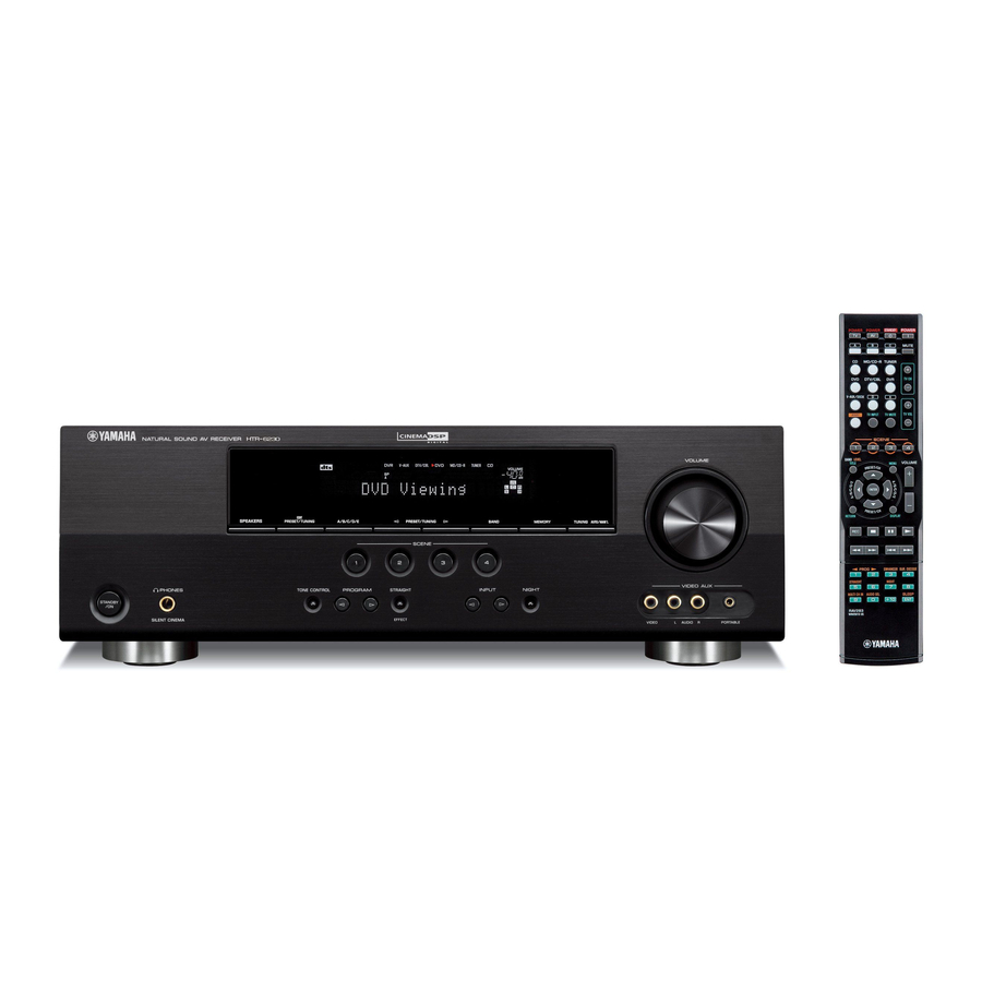
инструкцияYamaha HTR-6230

AV Receiver
OWNER’S MANUAL
F
Посмотреть инструкция для Yamaha HTR-6230 бесплатно. Руководство относится к категории приемники, 8 человек(а) дали ему среднюю оценку 7.8. Руководство доступно на следующих языках: русский, английский. У вас есть вопрос о Yamaha HTR-6230 или вам нужна помощь? Задайте свой вопрос здесь
- English
- Русский
Ресивер Yamaha HTR-6230 — это аудиоаппаратура для домашнего кинотеатра, предлагающая впечатляющий звуковой опыт. Он оснащен мощным усилителем, который обеспечивает чистоту звучания и высокую динамику. Данный ресивер имеет несколько аудио входов и выходов, включая HDMI, коаксиальные и оптические входы, что позволяет подключить различные аудиоисточники, такие как телевизоры, DVD-плееры и игровые приставки.
С помощью встроенного процессора звука Dolby Digital и DTS, ресивер Yamaha HTR-6230 обеспечивает пространственный и объемный звук, делая каждое воспроизведение звукового трека неповторимым и эмоциональным. Он также поддерживает режимы Hi-Fi и Cinema DSP, предоставляя настройки, которые оптимизируют качество звука в зависимости от предпочтений слушателя.
Располагая передним и задних каналами, ресивер Yamaha HTR-6230 создает многоканальный звук, превращая обычный домашний театр в настоящий кинозал. Благодаря встроенному AM/FM тюнеру, вы также можете настроиться на любимое радио и наслаждаться музыкой в высоком качестве звука.
В комплекте с ресивером поставляется пульт дистанционного управления, который позволяет удобно настраивать и управлять звуком. Кроме того, ресивер Yamaha HTR-6230 имеет компактный и стильный дизайн, который легко интегрируется с другими компонентами домашней аудиосистемы.
В целом, ресивер Yamaha HTR-6230 является надежным и функциональным устройством, которое позволяет наслаждаться качественным звуковым воспроизведением в домашней обстановке. Он идеально подходит для киноманов и меломанов, которые ценят потрясающее качество звука.
Главная
| Yamaha | |
| HTR-6230 | |
| приемник | |
| русский, английский | |
| Руководство пользователя (PDF) |
Не можете найти ответ на свой вопрос в руководстве? Вы можете найти ответ на свой вопрос ниже, в разделе часто задаваемых вопросов о Yamaha HTR-6230.
Когда звук считается слишком громким?
Уровень звука выше 80 децибел может нанести вред слуху. Уровень звука выше 120 децибел может нанести прямое повреждение слуху. Вероятность повреждения слуха зависит от частоты и продолжительности прослушивания.
Могут ли устройства разных марок подключаться друг к другу при помощи Bluetooth?
Да, Bluetooth — универсальный метод, позволяющий различным устройствам, оснащенным Bluetooth, подключаться друг к другу.
Что такое Bluetooth?
Bluetooth — это способ обмена данными по беспроводной сети между электронными устройствами с помощью радиоволн. Расстояние между двумя устройствами обменивающимися данными в большинстве случаев составляет не более десяти метров.
Что такое HDMI?
HDMI расшифровывается как «интерфейс для мультимедиа высокой четкости». Кабель HDMI используется для передачи аудио- и видеосигналов между устройствами.
Как лучше всего выполнять чистку приемник?
Для удаления отпечатков пальцев лучше всего использовать слегка влажную салфетку для уборки или мягкую чистую ткань. Пыль в труднодоступных местах лучше всего удаляется потоком сжатого воздуха.
Что такое Dolby Atmos?
Dolby Atmos — это технология, которая обеспечивает отражение звука от потолка к месту нахождения слушателя. Это позволяет создать эффект 5.1 при помощи всего лишь одного динамика.
Инструкция Yamaha HTR-6230 доступно в русский?
Да, руководствоYamaha HTR-6230 доступно врусский .
Не нашли свой вопрос? Задайте свой вопрос здесь
-
Contents
-
Table of Contents
-
Troubleshooting
-
Bookmarks
Quick Links
U
HTR-6230
AV Receiver
OWNER’S MANUAL
Related Manuals for Yamaha HTR 6230 — AV Receiver
Summary of Contents for Yamaha HTR 6230 — AV Receiver
-
Page 1
HTR-6230 AV Receiver OWNER’S MANUAL… -
Page 2: Important Safety Instructions
IMPORTANT SAFETY INSTRUCTIONS Ventilation – Slots and openings in the cabinet are provided for ventilation and to ensure reliable operation of the CAUTION product and to protect it from overheating, and these openings must not be blocked or covered. The openings RISK OF ELECTRIC SHOCK DO NOT OPEN should never be blocked by placing the product on a bed,…
-
Page 3: Note To Catv System Installer
Modifications not expressly approved by following measures: Yamaha may void your authority, granted by the FCC, to use the product. Relocate either this product or the device that is being 2 IMPORTANT: When connecting this product to affected by the interference.
-
Page 4
Yamaha la prise et pousser jusqu’au fond. will not be held responsible for any damage resulting from use Cet appareil numérique de la classe B est conforme à… -
Page 5: Table Of Contents
Contents INTRODUCTION ADVANCED OPERATION Features…………..2 Set menu …………..31 Supplied accessories ……….2 Using set menu…………32 Functional overview……….3 1 SOUND MENU………… 32 2 INPUT MENU…………34 Front panel …………..3 3 OPTION MENU ……….. 35 Front panel display…………. 4 Remote control features ……..
-
Page 6: Introduction
Bluetooth is a registered trademark of the Bluetooth SIG 1), Composite video (IN x 3, OUT x 2), Coaxial digital audio and is used by Yamaha in accordance with a license (IN x 1), Optical digital audio (IN x 2), Analog audio (IN x 9, OUT x 2) agreement.
-
Page 7: Functional Overview
Functional overview Front panel VOLUME EDIT SPEAKERS PRESET/TUNING A/B/C/D/E PRESET/TUNING BAND MEMORY TUNING AUTO/MAN’L SCENE VIDEO AUX PHONES TONE CONTROL PROGRAM STRAIGHT INPUT NIGHT STANDBY SILENT CINEMA EFFECT VIDEO AUDIO PORTABLE STANDBY/ON VOLUME control Turns on this unit, or sets it to standby mode (see page 15). Adjusts the volume level of this unit (see page 17).
-
Page 8: Front Panel Display
Lights up when headphones are connected and a sound field signal. program is selected (see page 26). DOCK indicator Lights up or flashes according to the state of Yamaha iPod universal dock or Bluetooth Wireless Audio Receiver connected to this unit (see pages 14 and 30). Input source indicators The corresponding cursor lights up to show the currently selected input source.
-
Page 9: Remote Control
Functional overview Remote control Press this button before you control this unit (see page 17). SCENE 1/2/3/4 Recalls an input source and a sound field program assigned to each SCENE button (see page 21). POWER POWER STANDBY POWER BAND LEVEL TITLE MUTE Selects the speaker that you want to adjust (see page 19).
-
Page 10: Rear Panel
DOCK terminal This input jacks support PCM, Dolby Digital and DTS bitstream (see page 11). Connect to the Yamaha iPod Universal Dock (such as YDS-11, • COAXIAL (DVD) sold separately) or Bluetooth Wireless Audio Receiver (such as • OPTICAL (DTV/CBL) YBA-10, sold separately) using its dedicated cable (see •…
-
Page 11: Quick Start Guide
• Connecting a multi-format player or an external We recommend magnetically shielded speakers. ☞P. 14 decoder ❏ Front speaker ……..x 2 • Connecting a Yamaha iPod universal dock or At least two front speakers are required to start ☞P. 14 Bluetooth Wireless Audio Receiver playback.
-
Page 12: Preparation
PREPARATION Preparation of remote control Installing batteries in the remote control Using the remote control The remote control transmits a directional infrared ray. Be sure to aim the remote control directly at the remote control sensor on this unit during operation. 30º…
-
Page 13: Connections
AUDIO OUTPUT (PLAY) CD-R (REC) the Yamaha Active Servo Processing Subwoofer System, WOOFER is effective not only for reinforcing bass frequencies from FRONT A any or all channels, but also for high fidelity sound reproduction of the LFE (low-frequency effect) channel included in Dolby Digital and DTS sources.
-
Page 14
Connections ■ Connecting to the FRONT A terminals Speakers Jacks on this unit a Front speaker (A) Right* FRONT A (R) b Front speaker (A) Left* FRONT A (L) c Surround speaker Right SURROUND (R) Red: positive (+) d Surround speaker Left SURROUND (L) Black: negative (–) e Center speaker… -
Page 15: Connecting Video Components
Connections VIDEO jacks Connecting video components For conventional composite video signals transmitted via composite video cables. Information on jacks and cable plugs COMPONENT VIDEO jacks For component signals, separated into the luminance (Y) Audio jacks and cable plugs and chrominance (P ) video signals transmitted on separate wires of component video cables.
-
Page 16: Connecting A Tv Monitor Or Projector
Connections Connecting a TV monitor or projector Make sure that this unit and other components are unplugged from the AC wall outlets. Note • If you turn off the video monitor connected to the HDMI OUT jack via a DVI connection, the connection may fail. In this case, the HDMI indicator flashes irregularly.
-
Page 17: Connecting Other Components
Connections Connecting other components Connecting audio and video components This unit has three types of audio jacks, two types of video jacks and HDMI jacks. You can choose the connection method depending on the component to be connected. ■ Connecting example (connecting a DVD player) ANTENNA DTV/CBL HDMI…
-
Page 18: Connecting A Yamaha Ipod Universal Dock Or Bluetooth Wireless Audio Receiver
Bluetooth Wireless Audio Receiver input jacks for the front and surround channels. This unit is equipped with the DOCK terminal on the rear panel that allows you to connect a Yamaha iPod universal MULTI CH INPUT DTV/CBL FRONT…
-
Page 19: Using The Video Aux Jacks On The Front Panel
If you experience poor reception quality, install an outdoor into the AC wall outlet. antenna. Consult the nearest authorized Yamaha dealer or service center about outdoor antennas. • The AM loop antenna should always be connected, even if an outdoor AM antenna is connected to this unit.
-
Page 20: Basic Setup
Basic setup The “BASIC SETUP” feature is a useful way to set up Choice Function your system quickly and with minimal effort. Applies the settings you made. CANCEL* Notes Cancels the setup procedure without making any changes. • Make sure that you disconnect your headphones from this unit. •…
-
Page 21: Basic Operation
BASIC OPERATION Playback Rotate PVOLUME (or press mVOLUME +/–) Caution Extreme caution should be exercised when you play to adjust the volume to the desired output back CDs encoded in DTS. If you play back a CD level. encoded in DTS on a DTS-incompatible CD player, you will only hear some unwanted noise that may damage your speakers.
-
Page 22: Additional Operations
Playback ■ Selecting the component connected to the Guide to contents MULTI CH INPUT jacks as the input source Use this feature to select the component connected to the When you want… See page MULTI CH INPUT jacks (see page 14) as the input source.
-
Page 23: Using Audio Features
Playback Using audio features • Once you press jBAND LEVEL TITLE on the remote control, you can also select the speaker by pressing lk / n. Use the following features to adjust the audio output or • The available speaker channels differ depending on the speaker settings.
-
Page 24: Signal Info
Playback ■ Using the sleep timer • “NIGHT:CINEMA” and “NIGHT:MUSIC” adjustments are stored Use this feature to automatically set this unit to the independently. standby mode after a certain amount of time. The sleep Notes timer is useful when you are going to sleep while this unit •…
-
Page 25: Selecting The Scene Templates
Selecting the SCENE templates Just by pressing one SCENE button, you can recall your Selecting the desired SCENE template favorite input source and sound field program according to the SCENE template that has been assigned to the SCENE If you want to use other SCENE templates, you can select button.
-
Page 26
SCENE template Input source Playback mode Features Select this SCENE template when you play back music on your iPod stationed in a Yamaha iPod Dock Listening DOCK Music Enh. 5ch universal dock or Bluetooth component that is connected to the Bluetooth receiver. -
Page 27: Creating Your Original Scene Templates
Note • When an iPod is connected to the Yamaha iPod universal dock or a Bluetooth component is connected to the Bluetooth receiver, this unit plays back the audio sources input at the DOCK terminal. Press lk / n to select the desired parameter…
-
Page 28: Using Remote Control On The Scene Feature
Selecting the SCENE templates Using remote control on the SCENE feature Controlling the input source components in the SCENE mode You can operate both this unit and the input source component by using the remote control. You must set the appropriate remote control code for each input source in advance (see page 39).
-
Page 29: Sound Field Programs
This unit is also equipped with a Yamaha digital sound • Sound field programs cannot be selected when the component connected to the MULTI CH INPUT jacks is selected as the input source (see field processing (DSP) chip containing several sound field page 18).
-
Page 30
Sound field programs ■ Selecting decoders for 2-channel sources CT WIDTH Center width (surround decode mode) Function: Adjusts the center image from all three front Signals input from 2-channel sources can also be played speakers to varying degrees. A larger value back on multi-channels. -
Page 31: Fm/Am Tuning
FM/AM tuning Overview To begin automatic tuning, press FPRESET/TUNING l / h once. To tune You can use two tuning modes to tune into a desired FM/ into the desired station manually, press AM station: FPRESET/TUNING l / h repeatedly. ■…
-
Page 32: Exchanging Preset Stations
FM/AM tuning Press EA/B/C/D/E (or ll / h) repeatedly to • You can select the preset station group and the preset station number where the first received station will be stored by pressing EA/B/C/D/E select the desired preset station group (A to and then FPRESET/TUNING l / h.
-
Page 33: Using Ipod
Using iPod™ Once you have stationed your iPod in a Yamaha iPod universal dock (such as the YDS-11, sold separately) connected to the DOCK terminal of this unit (see page 14), you can enjoy playback of your iPod using the supplied remote control.
-
Page 34: Using Bluetooth™ Components
• If the Bluetooth receiver is not connected to the DOCK terminal of this unit, “No BT adapter” appears on the front panel display. Check that the Bluetooth component detects the Bluetooth receiver. If the Bluetooth component detects the Bluetooth receiver, “YBA-10 YAMAHA” (example) appears in the Bluetooth device list.
-
Page 35: Advanced Operation
ADVANCED OPERATION Set menu You can use the following parameters in the set menu to adjust a variety of system settings and customize the way this unit operates. Change the initial settings to reflect the needs of your listening environment. BASIC SETUP Basic setup Use this feature to automatically adjust speaker and system parameters (see page 16).
-
Page 36: Using Set Menu
Set menu Using set menu 1 SOUND MENU Use the remote control to access and adjust each Use this menu to manually adjust any speaker settings or parameter. compensate for video signal processing delays when using LCD monitors or projectors. •…
-
Page 37
Set menu LFE signals output Notes Choice Subwoofer Front speakers Other speakers • The available speaker channels differ depending on the setting of the speakers. BOTH* Output No output No output • This does not affect recorded material. C)SP DISTANCE Speaker distance SWFR Output… -
Page 38: Input Menu
Set menu ■ ■ TEST A.DELAY Test tone Audio delay Use this feature to make adjustments for “CENTER GEQ” Use this feature to delay the sound output and synchronize while listening to a test tone. it with the video image. This may be necessary for certain LCD monitors or projectors.
-
Page 39: Option Menu
Set menu ■ The following is an example where “DVD” is renamed DTS decoder prioritize setting “My DVD.” Choice Function pDVD V-AUX DTV/CBL MD/CD-R TUNER AUTO* Automatically detect the type of input signals and selects the appropriate input mode. My DVD Enables to playback a DTS-CD.
-
Page 40: Start Pairing
Set menu C)AUDIO SELECT Press nRETURN to exit from “START Audio select PAIRING.” Use this feature to designate the default audio input jack select setting for the input sources. Notes • If the connected Bluetooth receiver cannot find any Bluetooth Choice Function components, “Not found”…
-
Page 41: Remote Control Features
Remote control features In addition to controlling this unit, the remote control can also operate other audiovisual components made by Yamaha and other manufacturers. To control your TV or other components, you must set up the appropriate remote control code for each input source (see page 39).
-
Page 42
Remote control features ■ Controlling other components Press one of the input selector buttons (f) or A to E buttons to control other components. You must set the appropriate remote control code for each input source in BAND LEVEL TITLE MENU VOLUME advance (see page 39). -
Page 43: Setting Remote Control Codes
Note are cleared and reset to the initial factory settings. • You may not be able to operate your Yamaha component even if a Yamaha remote control code is preset as listed above. In this case, try setting another Yamaha remote control code.
-
Page 44: Advanced Setup
Advanced setup This unit has additional menus that are displayed on the front panel display. The advanced setup menu offers additional operations to adjust and customize the way this unit operates. Change the initial settings (indicated by (*) in this following parameter) to reflect the needs of your listening environment.
-
Page 45: Additional Information
Refer to the table below when this unit does not function properly. If the problem you are experiencing is not listed below or if the instruction below does not help, turn off this unit, disconnect the power cable, and contact the nearest authorized Yamaha dealer or service center. ■…
-
Page 46
Troubleshooting Problem Cause Remedy page Sound is heard from Incorrect cable connections. Connect the cables properly. If the problem persists, 11-14 the speaker on one the cables may be defective. side only. Incorrect settings in “SP LEVEL.” Adjust the “SP LEVEL” settings. Only the center When playing a monaural source with a speaker outputs… -
Page 47
Troubleshooting Problem Cause Remedy page The sound field “MEM.GUARD” in “OPTION MENU” is Set “MEM.GUARD” to “OFF.” parameters and some set to “ON.” other settings of this unit cannot be changed. This unit does not The internal microcomputer has been Disconnect the power cable from the AC wall outlet —… -
Page 48
Remedy page Connect error There is a problem with the signal path Turn off this unit and reconnect the Yamaha iPod from your iPod to this unit. universal dock to the DOCK terminal of this unit. Try resetting your iPod. -
Page 49: Resetting The System
Troubleshooting ■ Remote control Problem Cause Remedy page The remote control Wrong distance or angle. The remote control functions within a maximum does not work nor range of 6 m (20 ft) and no more than 30 degrees off- function properly. axis from the front panel.
-
Page 50: Glossary
5-channel playback with 2 front left and right heard. Based on a wealth of actually measured data, Yamaha channels, 1 center channel, and 2 surround left and right channels…
-
Page 51: Specifications
Specifications AUDIO SECTION • Filter Characteristics (fc=40/60/80/90/100/110/120/160/200 Hz) H.P.F. (Front, Center, Surround) ……..12 dB/oct. • Minimum RMS Output Power for Front, Center, Surround L.P.F. (Subwoofer) …………24 dB/oct. [U.S.A. and Canada models] 1 kHz, 0.9% THD, 8 Ω ……….100 W/ch VIDEO SECTION [Other models] •…
-
Page 52: Index
■ Connecting the FM antennas ……15 Front speakers ……….32 Connecting the power cable ……15 NIGHT indicator ……….4 Connecting the Yamaha iPod ■ Night listening mode ……..19 universal dock ……….. 14 NIGHT, front panel ……… 3 G)AUDIO SET ……….34 Connecting to CD player …….
-
Page 53
Index ■ Subwoofer phase ……….33 Supplied accessories ……..2 Option menu ………..31 SUR. LR …………32 SUR.DECODE, remote control ……. 5 ■ Surround left/right speakers ……32 Pairing, Bluetooth control ……30 SWFR PHASE ……….33 PANORAMA ……….26 ■ Panorama …………26 Parameter initialization ……..36 TEST ………….. -
Page 54: List Of Remote Control Codes
List of remote control codes 2078 Yamaha 2000, 2001, 2003, Microsoft 2132 Blu-ray Player Medion 2072 2030, 2101 Mind 2132 Samsung 2137 Micromaxx 2072 Yukai 2078 Niveus Media 2132 Micromedia 2073 Zenith 2038, 2047, 2073 Northgate 2132 CD Player Microstar…
-
Page 55
Akai 0059, 0065, 0127, Cascade 0208 Envision 0060, 0061 Hisawa 0209, 0218 0129, 0130, 0200, Cathay 0213, 0217 Erres 0213, 0217 Hitachi 0006, 0014, 0015, 0204, 0208, 0209, 0127 0080 0016, 0042, 0060, 0213, 0217, 0218, Celebrity 0059 Etron 0208 0061, 0095, 0105, 0255 Centurion… -
Page 56
Lenco 0208 0026, 0053, 0060, 0182, 0194, 0195, Sanyo 0020, 0021, 0022, Lenoir 0207, 0208 0061, 0096, 0127 0211, 0213, 0216, 0049, 0060, 0064, Lesa 0214 Neckermann 0205, 0207, 0210, 0217, 0250 0127, 0128, 0200, Leyco 0206, 0213, 0217 0213, 0217, 0255 Plantron 0206, 0213 0203, 0207, 0215… -
Page 57
White Westinghouse Amstrad 1042 1045 Tatung 0127, 0204, 0207, 0200, 0207, 0217 Anitech 1050 Goodmans 1042, 1045, 1050, 0213, 0217, 0237 Yamaha 0000, 0001, 0002, 1045, 1046 1069 0206, 0208 0003, 0004, 0005, Asha 1002, 1014 Gradiente 1005 Teac 0127… -
Page 60
© 2009 Yamaha Corporation All rights reserved. Printed in China WQ96000… -
Page 61
HTR-6230 The letters in circles and the numbers in squares correspond to those in the Owner’s Manual. Les lettres dans les cercles et les numéros dans les carrés correspondent à ceux du mode d’emploi. ■ Front panel/Face avant VOLUME EDIT SPEAKERS PRESET/TUNING A/B/C/D/E… -
Page 62
■ Remote control/Boîtier de télécommande POWER POWER STANDBY POWER MUTE MD/CD-R TUNER TV CH DTV/CBL V-AUX/DOCK TV VOL TV INPUT TV MUTE SCENE BAND LEVEL VOLUME TITLE MENU ENTER RETURN DISPLAY PROG ENHANCER SUR.DECODE STRAIGHT NIGHT MULTI CH IN AUDIO SEL SLEEP Printed in China WQ96070…
Caution-i En
1 To assure the finest performance, please read this manual
carefully. Keep it in a safe place for future reference.
2 Install this sound system in a well ventilated, cool, dry, clean
place – away from direct sunlight, heat sources, vibration,
dust, moisture, and/or cold. Allow ventilation space of at least
30 cm on the top, 20 cm on the left and right, and 20 cm on
the back of this unit.
3 Locate this unit away from other electrical appliances, motors,
or transformers to avoid humming sounds.
4 Do not expose this unit to sudden temperature changes from
cold to hot, and do not locate this unit in an environment with
high humidity (i.e. a room with a humidifier) to prevent
condensation inside this unit, which may cause an electrical
shock, fire, damage to this unit, and/or personal injury.
5 Avoid installing this unit where foreign objects may fall onto
this unit and/or this unit may be exposed to liquid dripping or
splashing. On the top of this unit, do not place:
– Other components, as they may cause damage and/or
discoloration on the surface of this unit.
– Burning objects (i.e. candles), as they may cause fire,
damage to this unit, and/or personal injury.
– Containers with liquid in them, as they may fall and liquid
may cause electrical shock to the user and/or damage to
this unit.
6 Do not cover this unit with a newspaper, tablecloth, curtain,
etc. in order not to obstruct heat radiation. If the temperature
inside this unit rises, it may cause fire, damage to this unit,
and/or personal injury.
7 Do not plug in this unit to a wall outlet until all connections
are complete.
8 Do not operate this unit upside-down. It may overheat,
possibly causing damage.
9 Do not use force on switches, knobs and/or cords.
10 When disconnecting the power cable from the wall outlet,
grasp the plug; do not pull the cable.
11 Do not clean this unit with chemical solvents; this might
damage the finish. Use a clean, dry cloth.
12 Only voltage specified on this unit must be used. Using this
unit with a higher voltage than specified is dangerous and may
cause fire, damage to this unit, and/or personal injury. Yamaha
will not be held responsible for any damage resulting from use
of this unit with a voltage other than specified.
13 To prevent damage by lightning, keep the power cord and
outdoor antennas disconnected from a wall outlet or the unit
during a lightning storm.
14 Do not attempt to modify or fix this unit. Contact qualified
Yamaha service personnel when any service is needed. The
cabinet should never be opened for any reasons.
15 When not planning to use this unit for long periods of time
(i.e. vacation), disconnect the AC power plug from the wall
outlet.
16 Install this unit near the AC outlet and where the AC power
plug can be reached easily.
17 Be sure to read the “Troubleshooting” section on common
operating errors before concluding that this unit is faulty.
18 Before moving this unit, press
AST
ANDBY/ON to set this
unit in the standby mode, and disconnect the AC power plug
from the wall outlet.
19 VOLTAGE SELECTOR (Asia and General models only)
The VOLTAGE SELECTOR on the rear panel of this unit
must be set for your local main voltage BEFORE plugging
into the AC wall outlet. Voltages are:
…………..……………………..AC 110–120/220–240 V, 50/60 Hz
20 The batteries shall not be exposed to excessive heat such as
sunshine, fire or like.
21 Excessive sound pressure from earphones and headphones can
cause hearing loss.
22 When replacing the batteries, be sure to use batteries of the
same type. Danger of explosion may happen if batteries are
incorrectly replaced.
■ For U.K. customers
If the socket outlets in the home are not suitable for the
plug supplied with this appliance, it should be cut off and
an appropriate 3 pin plug fitted. For details, refer to the
instructions described below.
The plug severed from the mains lead must be destroyed, as a
plug with bared flexible cord is hazardous if engaged in a live
socket outlet.
■ Special Instructions for U.K. Model
Caution: Read this before operating your unit.
WARNING
TO REDUCE THE RISK OF FIRE OR ELECTRIC
SHOCK, DO NOT EXPOSE THIS UNIT TO RAIN
OR MOISTURE.
As long as this unit is connected to the AC wall outlet,
it is not disconnected from the AC power source even
if you turn off this unit by ASTANDBY/ON. In this
state, this unit is designed to consume a very small
quantity of power.
Note
IMPORTANT
THE WIRES IN MAINS LEAD ARE COLOURED IN
ACCORDANCE WITH THE FOLLOWING CODE:
Blue: NEUTRAL
Brown: LIVE
As the colours of the wires in the mains lead of this apparatus
may not correspond with the coloured markings identifying
the terminals in your plug, proceed as follows:
The wire which is coloured BLUE must be connected to the
terminal which is marked with the letter N or coloured
BLACK. The wire which is coloured BROWN must be
connected to the terminal which is marked with the letter L or
coloured RED.
Making sure that neither core is connected to the earth
terminal of the three pin plug.
Caution-ii En
Caution: Read this before operating your unit.
Information for Users on Collection and Disposal of Old Equipment and used Batteries
These symbols on the products, packaging, and/or accompanying documents mean that used electrical
and electronic products and batteries should not be mixed with general household waste.
For proper treatment, recovery and recycling of old products and used batteries, please take them to
applicable collection points, in accordance with your national legislation and the Directives 2002/96/
EC and 2006/66/EC.
By disposing of these products and batteries correctly, you will help to save valuable resources and
prevent any potential negative effects on human health and the environment which could otherwise
arise from inappropriate waste handling.
For more information about collection and recycling of old products and batteries, please contact your
local municipality, your waste disposal service or the point of sale where you purchased the items.
[Information on Disposal in other Countries outside the European Union]
These symbols are only valid in the European Union. If you wish to discard these items, please contact
your local authorities or dealer and ask for the correct method of disposal.
Note for the battery symbol (bottom two symbol examples):
This symbol might be used in combination with a chemical symbol. In this case it complies with the
requirement set by the Directive for the chemical involved.

1 En
English
INTRODUCTION
ADDITIONAL
INFORMATION APPENDIX
PREPARATION
BASIC
OPERATION
ADVANCED
OPERATION
Features……….……….………………………………………… 2
Supplied accessories ………………..………….…………….. 2
Functional overview…………..……….……………………3
Front panel …………….…………….…………….…………….. 3
Front panel display………..………………………….……….. 4
Remote control………………..…………….………………….. 5
Rear panel …..……………………….…………….…………….. 6
Quick start guide…………..………………….…………….. 7
L
Preparation of remote control …………………………. 8
Connections ……..…………………………….………………. 9
Placing speakers……………………………….……………….. 9
Connecting speakers ………………………………………….. 9
Connecting video components……..………….………… 11
Connecting other components …………………………… 13
Using the VIDEO AUX jacks on the front panel …. 14
Connecting the FM and AM antennas ………………… 15
Connecting the power cable………………….…………… 15
Turning on and off the power ……………….…………… 15
Optimizing the speaker setting for your listening
room (YPAO) …………………….………………….….. 16
Using AUTO SETUP……….…………….………………… 16
Playback………………………….…………………………….18
Basic procedure…………………….…………….…………… 18
Additional operations……….…………….………………… 19
Selecting the SCENE templates ……….……………..22
Selecting the desired SCENE template..……………… 22
Creating your original SCENE templates ……….…… 24
Sound field programs …………………………………….25
Selecting sound field programs…………..……………… 25
FM/AM tuning ……………..………………….…………… 27
Overview……………….…………….………….……………… 27
FM/AM tuning operations …..…………….……………… 27
Preset FM/AM stations ……………….…………….……… 27
Radio Data System tuning (Europe and Russia
models only)……………………….………………….….. 29
Displaying the Radio Data System information …… 29
Selecting the Radio Data System program type (PTY
SEEK mode) ……………….……………………….……… 29
Using the enhanced other networks (EON) data
service…….……………………….…………….…………… 30
Set menu ………………………….………………….……….. 31
Using set menu………………….……………………….……. 32
1 SOUND MENU ……………..……………………….……. 32
2 INPUT MENU ……………………….…………….………. 34
3 OPTION MENU ………………….…………….…………. 35
Advanced setup…..………………….………………….…. 37
Troubleshooting…………..……….………………………. 38
Glossary …..……….………………….………………………. 43
Specifications…..………………………….………………… 44
Index ………………..……….…………………………………. 45
Contents
INTRODUCTION
PREPARATION
BASIC OPERATION
ADVANCED OPERATION
ADDITIONAL INFORMATION
About this manual
• y indicates a tip for your operation.
• Some operations can be performed by using either the buttons on the
front panel or the ones on the remote control. In case the button
names differ between the front panel and the remote control, the
button name on the remote control is given in parentheses.
• This manual is printed prior to production. Design and specifications
are subject to change in part as a result of improvements, etc. In case
of differences between the manual and product, the product has
priority.
• “ASTANDBY/ON” or “eDVD” (example) indicates the name of
the parts on the front panel or the remote control. Refer to the
“Functional overview” on page 3.

2 En
INTRODUCTION
Built-in 5-channel power amplifier
◆ Minimum RMS output power
(1 kHz, 0.9% THD, 6 Ω)
Front: 100 W/ch
Center: 100 W
Surround: 100 W/ch
Various input/output connectors
◆ HDMI (IN x 2, OUT x 1), Component video (IN x 3, OUT x
1), Composite video (IN x 3, OUT x 2), Coaxial digital audio
(IN x 1), Optical digital audio (IN x 2), Analog audio (IN x 9,
OUT x 2)
◆ Speaker out (5-channel), Subwoofer out
◆ Discrete multi-channel input (6-channel)
SCENE select function
◆ Preset SCENE templates for various situations
◆ SCENE template customizing capability
Sound field programs
◆ Proprietary Yamaha technology for the creation of surround
field
◆ Compressed Music Enhancer mode
◆ SILENT CINEMA™
Decoders and DSP circuits
◆ Dolby Digital decoder
◆ Dolby Pro Logic/Dolby Pro Logic II decoder
◆ DTS decoder
◆ Virtual CINEMA DSP
◆ SILENT CINEMA™
Sophisticated FM/AM tuner
◆ 40-station random and direct preset tuning
◆ Automatic preset tuning
HDMI™ (High-Definition Multimedia Interface)
◆ HDMI interface for standard, enhanced or high-definition
video (includes 1080p video signal transmission)
Other features
◆ 192-kHz/24-bit D/A converter
◆ Sleep timer
◆ Cinema and music night listening modes
◆ Remote control capability
Manufactured under license from Dolby Laboratories.
“Dolby,” “Pro Logic,” and the double-D symbol are
trademarks of Dolby Laboratories.
Manufactured under license under U.S. Patent No’s:
5,451,942;5,956,674;5,974,380;5,978,762;6,487,535 and
other U.S. and worldwide patents issued and pending.
DTS is a registered trademark and the DTS logos and
symbol are trademarks of DTS, Inc. © 1996-2007 DTS,
Inc. All Rights Reserved.
“HDMI,” the “HDMI” logo and “High-Definition
Multimedia Interface” are trademarks, or registered
trademarks of HDMI Licensing LLC.
“SILENT CINEMA” is a trademark of Yamaha
Corporation.
Check that you received all of the following parts.
❏ Remote control
❏ Batteries (2) (AAA, R03, UM-4)
❏ AM loop antenna
❏ Indoor FM antenna
❏ Optimizer microphone
Features
Supplied accessories
3 En
English
INTRODUCTION
ADDITIONAL
INFORMATION APPENDIX
PREPARATION
BASIC
OPERATION
ADVANCED
OPERATION
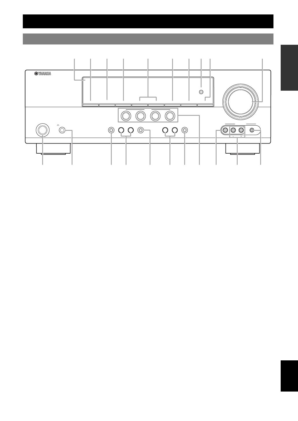
A STANDBY/ON
Turns on this unit, or sets it to standby mode (see page 15).
B PHONES jack
Connect to a pair of headphones (see page 20).
C SPEAKERS
Turns on or off the set of front speakers connected to the
FRONT A or FRONT B speaker terminals (see page 19).
D EDIT PRESET/TUNING
Switches the tuning mode (see page 27).
E A/B/C/D/E
Selects the preset station group (A to E) (see page 28).
F PRESET/TUNING l / h
Tunes into radio stations manually or automatically and selects a
preset station group (see page 27).
G BAND
Selects the reception band from FM and AM (see page 27).
H MEMORY
Stores a station that you tuned into as a preset station (see
page 27).
I TUNING AUTO/MAN’L
Selects a tuning method from automatic or manual tuning (see
page 27).
J SCENE 1/2/3/4
Recalls an input source and a sound field program assigned to
each SCENE button (see page 22).
K TONE CONTROL
Selects “BASS” and “TREBLE” to adjust frequency response
(see page 20).
L PROGRAM l / h
Selects a sound field program (see page 25).
M STRAIGHT
Activates the “STRAIGHT” mode (see page 26).
N INPUT l / h
Selects an input source (see page 18).
O NIGHT
Selects a night listening mode (see page 20).
P VOLUME control
Adjusts the volume level of this unit (see page 18).
Q VIDEO (VIDEO AUX) jack
Connects to a game console or a video camera using a
composite video cable (see page 14).
R AUDIO L/R (VIDEO AUX) jacks
Connects to a game console or a video camera using analog
audio cables (see page 14).
S PORTABLE (VIDEO AUX) jack
Connects to an audio component (such as iPod) (see page 14).
T OPTIMIZER MIC jack
Connect to the supplied optimizer microphone (see page 16).
U Front panel display
Shows information about the operational status of this unit (see
page 18).
Functional overview
Front panel
OPTIMIZER
MIC
PHONES
SILENT
CINEMA
TONE
CONTROL
PROGRAM
STRAIGHT
INPUT
VIDEO
AUDIO
PORTABLE
VIDEO
AUX
VOLUME
EFFECT
l
h
l
h
SCENE
STANDBY
/ON
1
NIGHT
2
3
4
SPEAKERS
PRESET/TUNING
EDIT
A/B/C/D/E
PRESET/TUNING
l
h
BAND
MEMORY
TUNING
AUTO/MAN’L
A
K OL N
J Q SB RM
4 En
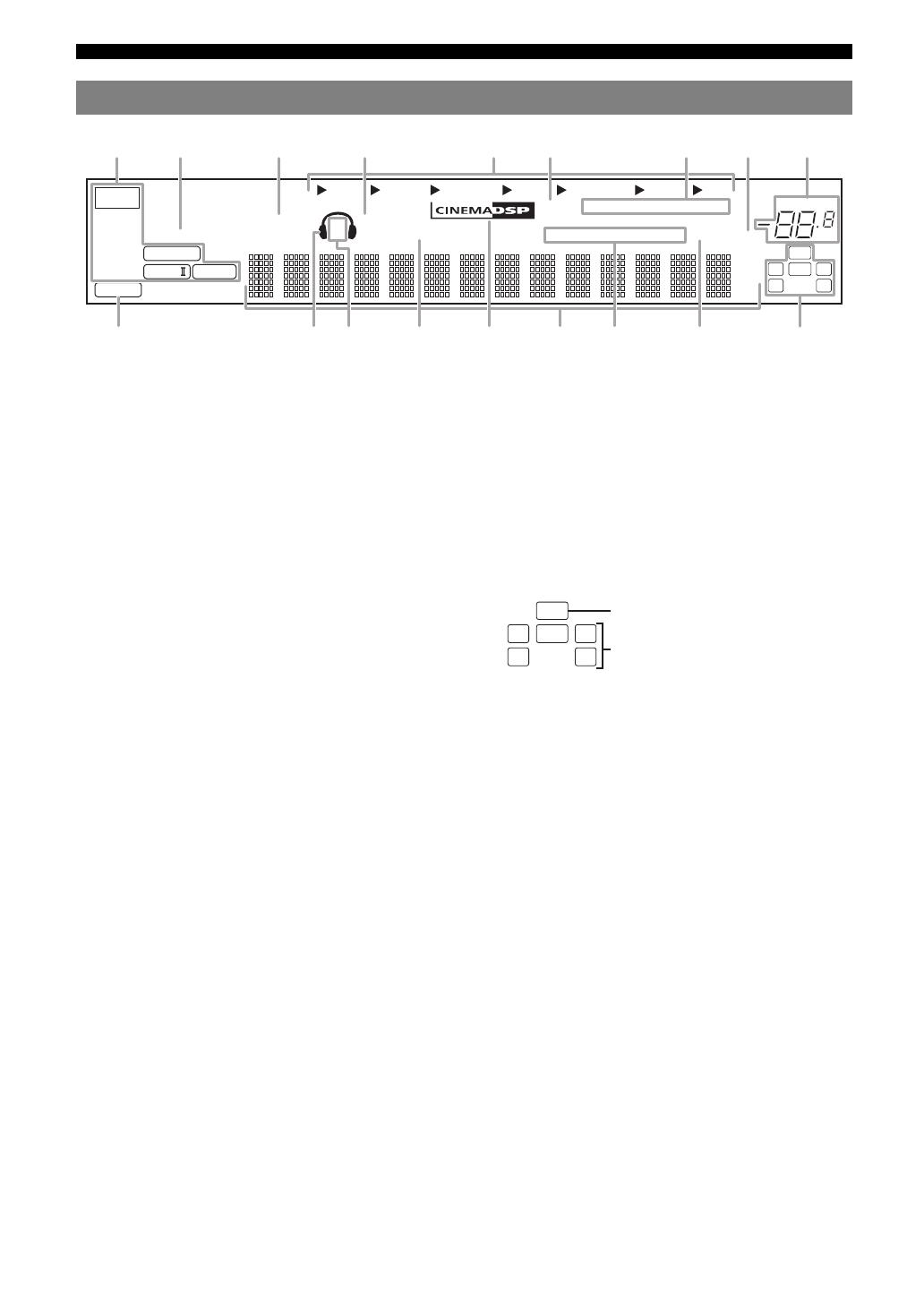
Functional overview
a Decoder indicator
Lights up when any of the decoders of this unit functions.
b ENHANCER indicator
Lights up when the Compressed Music Enhancer mode is
selected (see page 25).
c VIRTUAL indicator
Lights up when Virtual CINEMA DSP is active (see page 26).
d SILENT CINEMA indicator
Lights up when headphones are connected and a sound field
program is selected (see page 26).
e Input source indicators
The corresponding cursor lights up to show the currently
selected input source.
f YPAO indicator
Lights up when you run “AUTO SETUP” and when the speaker
settings set in “AUTO SETUP” are used without any
modifications (see page 16).
g Tuner indicators
Lights up when this unit is in the FM or AM tuning mode (see
page 27).
h MUTE indicator
Flashes while the MUTE function is on (see page 20).
i VOLUME level indicator
Indicates the current volume level.
j PCM indicator
Lights up when this unit is reproducing PCM (Pulse Code
Modulation) digital audio signals.
k Headphones indicator
Lights up when headphones are connected (see page 20).
l SP A B indicators
Lights up according to the set of front speakers selected (see
page 18).
m NIGHT indicator
Lights up when you select a night listening mode (see page 20).
n CINEMA DSP indicator
Lights up when you select a sound filed program (see page 26).
o Multi-information display
Shows the name of the current sound field program and other
information when adjusting or changing settings.
p Radio Data System indicators (Europe and Russia
models only)
• PTY HOLD
Lights up when this unit is in the PTY SEEK mode (see
page 29).
• PS, PTY, RT and CT
Light up according to the available Radio Data System
information.
•EON
Lights up when the EON data service is available.
q SLEEP indicator
Lights up while the sleep timer is on (see page 21).
r Input channel and speaker indicators
• LFE indicator
Lights up when the input signal contains the LFE signal.
• Input channel indicators
Indicates the channel components of the current digital input
signal.
Front panel display
DVR DVD CD
V-AUX DTV/CBL
MD/CD-R
TUNER
q
PL
q
PL
ENHANCER
SILENT CINEMA
NIGHT
AUTO
YPAO
PRESET
PSHOLD RT
EON
PTYPTY
TUNED
MUTE
VOLUME
MEMORY
SLEEP
VIRTUAL
PCM
A B
SP
mS
ft
dB
LFE
LCR
SL SR
q
DIGITAL
t
dB
STEREO
CT
LFE
LCR
SL SR
LFE indicator
Input channel indicators
5 En
Functional overview
English
INTRODUCTION
ADDITIONAL
INFORMATION APPENDIX
PREPARATION
BASIC
OPERATION
ADVANCED
OPERATION
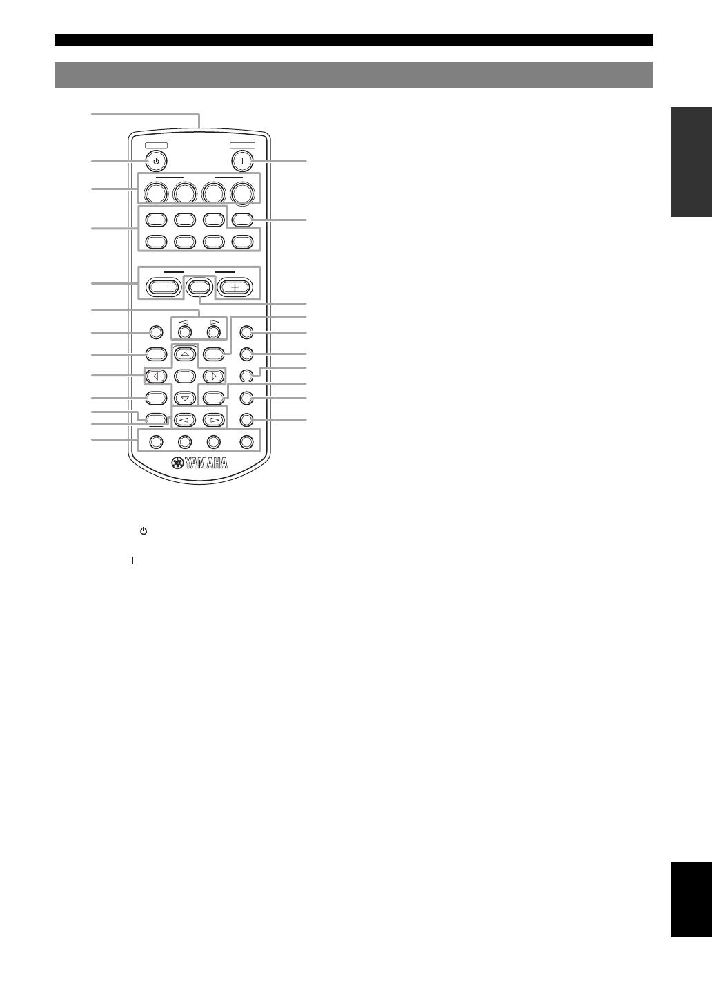
a Infrared window
Outputs infrared control signals (see page 8).
b STANDBY ( )
Sets this unit to the standby mode (see page 15).
c POWER ( )
Turns this unit on (see page 15).
d SCENE 1/2/3/4
Recalls an input source and a sound field program assigned to
each SCENE button (see page 22).
e Input selector buttons
Switches the input source to each source (see page 18).
f MULTI CH IN
Sets the input source to MULTI CH IN (see page 19).
g VOLUME +/–
Adjusts the volume level of this unit (see page 18).
h MUTE
Mutes audio output. Press the button again to resume audio
output (see page 20).
i PRESET l / h
Tunes into radio stations manually or automatically and selects a
Preset station number (1 to  (see page 27).
j A/B/C/D/E
Selects the preset station group (A to E) (see page 28).
k MENU
Displays the set menu on the front panel display (see page 32).
l SLEEP
Sets the sleep timer (see page 21).
m LEVEL
Selects the speaker that you want to adjust (see page 20).
n AUDIO SEL
Selects an audio input select setting for each input source (see
page 19).
o Cursors (l / h / n / k) / ENTER
• Press cursors to navigate the set menu (see page 32).
• Press ENTER to confirm a selection in the set menu (see
page 32).
p NIGHT
Selects a night listening mode (see page 20).
q RETURN
Returns the previous menu level in the set menu mode (see
page 32).
r SUR.DECODE
Selects a decoder from four decoders (see page 26).
s DISPLAY
Is not available for this unit.
t STRAIGHT
Activates the “STRAIGHT” mode (see page 26).
u PROG l / h
Selects the sound field program (see page 25).
v ENHANCER
Sets the sound field program to the “Music Enh. 2ch” or “Music
Enh. 5ch” (see page 25).
w INFO/Radio data system control
Controls the Radio Data System with 4-buttons (INFO/EON/
MODE (PTY-SEEK)/START (PTY-SEEK)) (see page 29).
Remote control
STANDBY
SCENE
POWER
CD
DVD
A/B/C/D/E
PRESET
SLEEP
LEVEL
MENU
AUDIO SEL
NIGHT
RETURN
SUR.DECODE
STRAIGHT
INFO EON
PTY
MODE
PROG
ENHANCER
DISPLAY
ENTER
MUTE
DVR
V-AUX
DTV/CBL
MD/CD-R
TUNER
MULTI CH IN
1234
VOLUME
START
SEEK
b
d
g
k
s
p
t
h
c
f
l
n
r
v
j
m
q
e
i
u
w
o
6 En
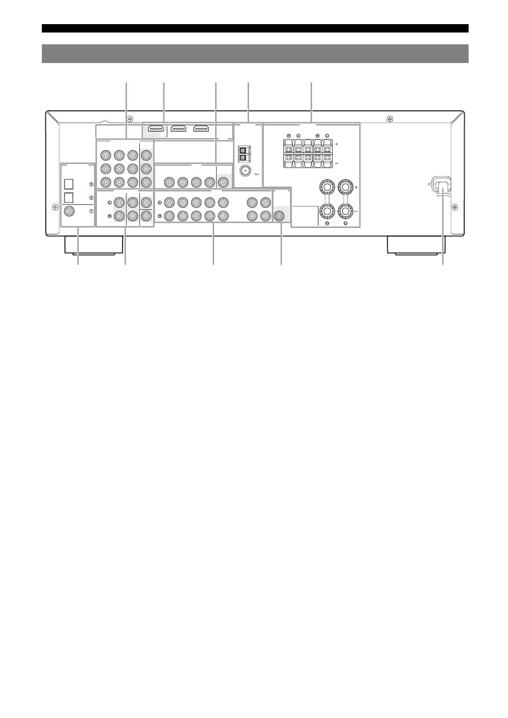
Functional overview
a COMPONENT VIDEO jacks
Connect to Y, PB/CB and PR/CR jacks on your video components
with component video cables (see page 11).
• DVD input jacks
• DTV/CBL input jacks
• DVR input jacks
• MONITOR OUT output jacks
b HDMI terminals
Connect to HDMI output/input terminals on your external
components with HDMI cables (see page 11).
• HDMI DVD terminal
• HDMI DTV/CBL terminal
• HDMI OUT output terminal
c VIDEO jacks
Connect to video jacks on your video components with
composite video cables (see page 11).
• DVD input jack
• DTV/CBL input jack
• DVR IN jack
• DVR OUT jack
• MONITOR OUT jack
d ANTENNA terminals
Connect to the supplied FM and AM antennas (see page 15).
e SPEAKERS terminals
Connect to each speakers (see page 9).
• FRONT A L/R
• FRONT B L/R
• SURROUND L/R
• CENTER
f DIGITAL INPUT jacks
Connect to the DIGITAL output jacks on your digital audio
components with Coaxial/Optical digital audio cables.
This input jacks support PCM, Dolby Digital and DTS bitstream
(see page 11).
• COAXIAL (DVD)
• OPTICAL (DTV/CBL)
• OPTICAL (CD)
g MULTI CH INPUT jacks
Connect to the output jacks on your multi-format player or
external decoder with analog audio cables (see page 14).
• FRONT L/R jack
• SURROUND L/R jack
•CENTER jack
• SUBWOOFER jack
h AUDIO jacks
Connect to the audio output/input jacks on your components
with analog audio cables (see page 11).
• DVD L/R jack
• DTV/CBL L/R jack
• DVR IN L/R jack
• DVR OUT L/R jack
• CD L/R jack
• IN (PLAY) L/R jack
• OUT (REC) L/R jack
i SUBWOOFER OUTPUT jack
Connect to a Subwoofer with an analog audio cable (see
page 9).
j Power cable
Connect to a standard AC outlet (see page 15).
Rear panel
DIGITAL INPUT
COMPONENT VIDEO
VIDEO
AUDIO
MULTI CH INPUT
HDMI
ANTENNA
SPEAKERS
DVD
OPTICAL
DVD
SURROUND
CENTER
FRONT B
FRONT A
DVR
SURROUND
FRONT
CENTER
SUBWOOFER
DTV/CBL
DVD
DVR
FM
AM
GND
IN
OUT
DTV/CBL
DVD
DVR
CD
OUTPUT
SUB
WOOFR
IN
OUT
MD/
CD-R
IN
(PLAY)
OUT
(REC)
DTV/CBL
DTV/CBL
MONITOR
OUT
MONITOR
OUT
CD
P
R
P
B
Y
DVD
COAXIAL
DTV/
CBL
OUT
UNBAL.
f g h i
j
7 En
English
INTRODUCTION
ADDITIONAL
INFORMATION APPENDIX
PREPARATION
BASIC
OPERATION
ADVANCED
OPERATION
The following steps describe the easiest way to operate this unit. See the related pages for details on the operation and
settings.
In these steps, you need the following items which are not
included in the package of this unit.
❏ Speakers
We recommend magnetically shielded speakers.
❏ Front speaker ………………………….…… x 2
At least two front speakers are required to start
playback.
❏ Center speaker …………………………….. x 1
❏ Surround speaker ………….…………….. x 2
❏ Active subwoofer …………………………….. x 1
Select an active subwoofer equipped with an RCA
input jack.
❏ Speaker cable ……….………………..……….. x 5
❏ Subwoofer cable ………………..…………….. x 1
Select a monaural RCA cable.
❏ DVD player ……………………………….……… x 1
Select DVD player equipped with coaxial digital
audio output jack and composite video output jack.
❏ Video monitor ……….………………..……….. x 1
Select a TV monitor, video monitor or projector
equipped with a composite video input jack.
❏ Video cable ………………….………………..… x 2
Select an RCA composite video cable.
❏ Digital coaxial audio cable ……………….. x 1
Place your speakers in the room and connect them to this
unit.
Connect your TV, DVD player or other components.
Connect the power cable and turn on this unit.
Select the component connected in the step 3 as an input
source and start playback.
Quick start guide
Step 1: Check the items
Step 2: Set up your speakers
• Placing speakers ☞P. 9
• Connecting speakers ☞P. 9
Video monitor
Front left
speaker
Center speaker
DVD player
Surround left
speaker
Surround right
speaker
Subwoofer
Front right
speaker
Step 3: Connect your components
• Connecting a TV monitor or projector ☞P. 1 2
• Connecting audio and video components ☞P. 1 3
• Connecting a multi-format player or an external
decoder ☞P. 1 4
• Using the VIDEO AUX jacks on the front panel
☞P. 1 4
• Connecting the FM and AM antennas ☞P. 1 5
Step 4: Turn on the power
• Connecting the power cable ☞P. 1 5
• Turning on and off the power ☞P. 1 5
Step 5: Select the input source and start
playback
• Basic procedure ☞P. 1 8
• Selecting the SCENE templates ☞P. 2 2
• Adjusting the sound field programs ☞P. 2 5
8 En
PREPARATION
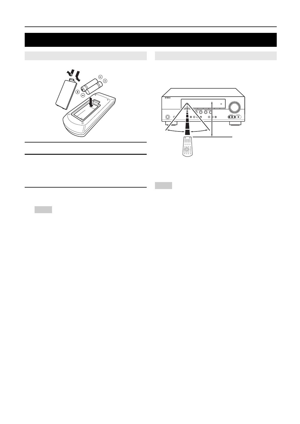
1 Take off the battery compartment cover.
2 Insert the four supplied batteries (AAA, R03,
UM-4) according to the polarity markings (+
and –) on the inside of the battery
compartment.
3 Snap the battery compartment cover back
into place.
Notes
• Change all of the batteries if you notice the following conditions:
– the operation range of the remote control decreases.
• Do not use old batteries together with new ones.
• Do not use different types of batteries (such as alkaline and
manganese batteries) together. Read the packaging carefully as
these different types of batteries may have the same shape and
color.
• If the batteries have leaked, dispose of them immediately. Avoid
touching the leaked material or letting it come into contact with
clothing, etc. Clean the battery compartment thoroughly before
installing new batteries.
• Do not throw away batteries with general house waste; dispose of
them correctly in accordance with your local regulations.
The remote control transmits a directional infrared ray.
Be sure to aim the remote control directly at the remote
control sensor on this unit during operation.
a Infrared window
Outputs infrared control signals. Aim this window at the
component you want to operate.
Notes
• Do not spill water or other liquids on the remote control.
• Do not drop the remote control.
• Do not leave or store the remote control in the following types of
conditions:
– places of high humidity, such as near a bath
– places of high temperature, such as near a heater or stove
– places of extremely low temperatures
– dusty places
Preparation of remote control
Installing batteries in the remote control
1
3
2
Using the remote control
30º 30º
Approximately 6 m (20 ft)
9 En
English
INTRODUCTION
ADDITIONAL
INFORMATION APPENDIX
PREPARATION
BASIC
OPERATION
ADVANCED
OPERATION
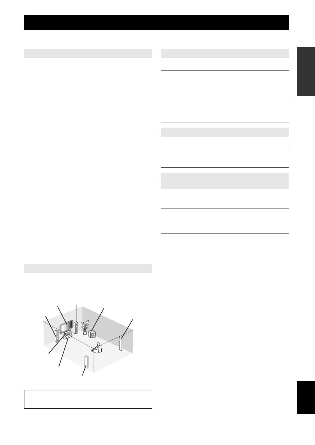
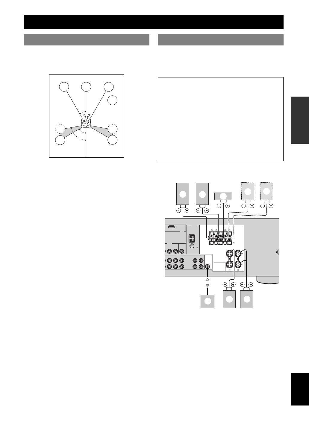
The speaker layout below shows the speaker setting we
recommend. You can use it to enjoy CINEMA DSP and
multi-channel audio sources.
Front left and right speakers (FL and FR)
The front speakers are used for the main source sound plus
effect sounds. Place these speakers at an equal distance
from the ideal listening position. The distance of each
speaker from each side of the video monitor should be the
same.
Center speaker (C)
The center speaker is for the center channel sounds
(dialog, vocals, etc.). If for some reason it is not practical
to use a center speaker, you can do without it. Best results,
however, are obtained with the full system.
Surround left and right speakers (SL and SR)
The surround speakers are used for effect and surround
sounds.
Subwoofer (SW)
The use of a subwoofer with a built-in amplifier, such as
the Yamaha Active Servo Processing Subwoofer System,
is effective not only for reinforcing bass frequencies from
any or all channels, but also for high fidelity sound
reproduction of the LFE (low-frequency effect) channel
included in Dolby Digital and DTS sources. The position
of the subwoofer is not so critical, because low bass
sounds are not highly directional. But it is better to place
the subwoofer near the front speakers. Turn it slightly
toward the center of the room to reduce wall reflections.
Be sure to connect the left channel (L), right channel (R),
“+” (red) and “–” (black) properly. If the connections are
faulty, this unit cannot reproduce the input sources
accurately.
■ 5.1-channel speaker connection
Connections
Placing speakers
60˚
30˚
FL
FR
C
SL
SR
SR
80˚
SL
SW
Connecting speakers
Caution
• Use speakers with the specified impedance shown on
the rear panel of this unit.
• Before connecting the speakers, make sure that this
the AC power plug is disconnected from the AC wall
outlet.
• Do not let the bare speakers wires touch each other or
do not let them touch any metal part of this unit. This
could damage this unit and/or speakers.
• Use magnetically shielded speakers. If this type of
speaker still creates interference with the monitor,
place the speakers away from the monitor.
LRLR
LR
HDMI
VIDEO
AUDIO OUTPUT
ANTENNA
SPEAKERS
L
DTV/CBL
SURROUND CENTER FRONT B
FRONT A
MONITOR
OUT
MD/
CD-R
SUB
WOOFER
OUT
(REC)
IN
(PLAY)
DVR
L DVR CD
IN
OUT
IN
OUT
AM
GND
FM
75
UNBAL.
a b
c
d
f
g
e
h
10 En
Connections
* You can select the front speaker set from Front speakers (A) and Front
speakers (B) by pressing CSPEAKERS repeatedly. See page 19 for
details.
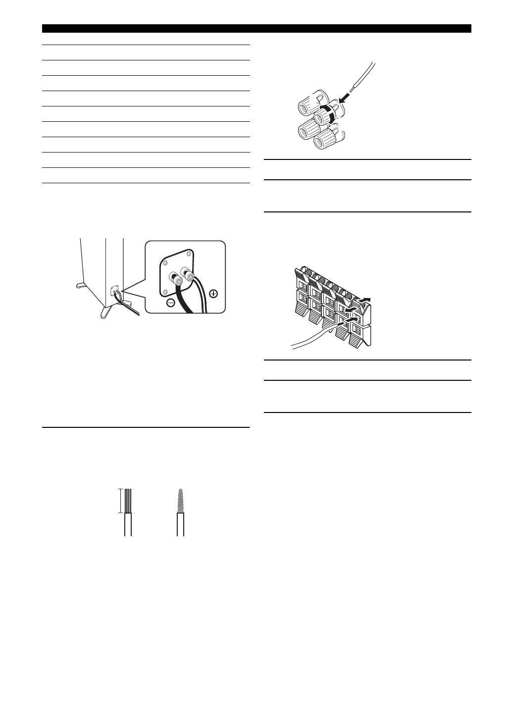
■ Connect speaker cables to each speaker
Cables are colored or shaped differently, perhaps with a
stripe, groove or ridge. Connect the striped (grooved, etc.)
cable to the “+” (red) terminals of your speaker. Connect
the plain cable to the “–” (black) terminals.
■ Before connecting to the SPEAKERS
terminal
A speaker cord is actually a pair of insulated cables
running side by side.
Remove approximately 10 mm (3/8”) of insulation
from the end of each speaker cable and then
twist the bare wires of the cable together to
prevent short circuits.
■ Connecting to the FRONT A terminals
1 Loosen the knob.
2 Insert the bare end of the speaker wire into
the slit on the terminal.
3 Tighten the knob to secure the wire.
■ Connecting to the FRONT B, CENTER, and
SURROUND terminals
1 Press down the tab.
2 Insert the bare end of the speaker wire into
the hole on the terminal.
3 Release the tab to secure the wire.
Speakers Jacks on this unit
a Front speaker (A) Right* FRONT A (R)
b Front speaker (A) Left* FRONT A (L)
c Surround speaker Right SURROUND (R)
d Surround speaker Left SURROUND (L)
e Center speaker CENTER
f Front speaker (B) Right* FRONT B (R)
g Front speaker (B) Left* FRONT B (L)
h Subwoofer SUBWOOFER
10 mm (3/8”)
1
2
3
Red: positive (+)
Black: negative (–)
Red: positive (+)
Black: negative (–)
11 En
Connections
English
INTRODUCTION
ADDITIONAL
INFORMATION APPENDIX
PREPARATION
BASIC
OPERATION
ADVANCED
OPERATION
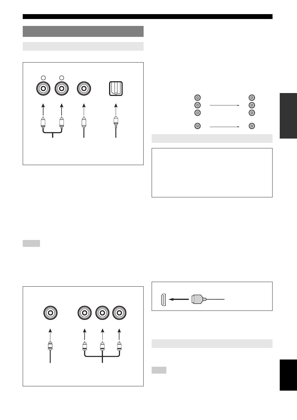
Audio jacks and cable plugs
AUDIO jacks
For conventional analog audio signals transmitted via left
and right analog audio cables. Connect red plugs to the
right jacks and white plugs to the left jacks.
COAXIAL jack
For digital audio signals transmitted via coaxial digital
audio cable.
OPTICAL jacks
For digital audio signals transmitted via optical digital
audio cables.
Notes
• You can use the digital jacks to input PCM, Dolby Digital, and DTS
bitstreams. All digital input jacks are compatible with digital signals with
up to 96 kHz of sampling frequency.
• This unit handles digital and analog signals independently. Thus audio
signals input at the digital jacks are not output at the analog AUDIO OUT
(REC) jack.
Video jacks and cable plugs
VIDEO jacks
For conventional composite video signals transmitted via
composite video cables.
COMPONENT VIDEO jacks
For component signals, separated into the luminance (Y)
and chrominance (P
B, PR) video signals transmitted on
separate wires of component video cables.
You can play back pictures by connecting your video
monitor and video source component to this unit using
HDMI connections.
At that time, audio/video signals output from the
connected component (such as DVD player etc.) are
output to the connected video monitor only when this unit
is turned on and set to the input source (DVD or DTV/
CBL).
Furthermore, available audio/video signals depend on the
specification of the connected video monitor. Refer to the
instruction manual of each connected component.
■ HDMI jack and cable plug
y
• We recommend using an HDMI cable shorter than 5 meters (16 feet)
with the HDMI logo printed on it.
• Use a conversion cable (HDMI jack ↔ DVI-D jack) to connect this unit
to other DVI components.
You can record the audio signal output at the AUDIO
OUT (REC) jack by using the recording components.
Note
• Check the copyright laws in your country to record from CDs, radio, etc.
Recording of copyrighted material may infringe copyright laws.
Connecting video components
Information on jacks and cable plugs
COAXIAL
DIGITAL AUDIO
AUDIO
OPTICAL
DIGITAL AUDIO
R
L
C
O
R
L
(White) (Red) (Orange)
Left and right
analog audio
cable plugs
Coaxial
digital audio
cable plug
Optical
digital
audio cable
plug
VIDEO
COMPONENT VIDEO
Y P
B
P
R
PB
Y
P
R
V
(Yellow) (Blue) (Red)(Green)
Composite
video cable
plug
Component
video cable
plugs
Information on HDMI™
Audio signals input at the HDMI jack are not output
from any speaker terminals but output from the
connected video monitor. To enjoy the sound from
speakers connected to this unit,
– make an analog or digital connection besides the
HDMI connection (see page 13).
– mute the volume of the connected video monitor.
Using the AUDIO OUT REC jack
PR
P
B
Y
P
R
P
B
Y
COMPONENT
VIDEO
VIDEO
Video signal flow for MONITOR OUT
Input
Output
(MONITOR OUT)
HDMI
HDMI cable plug
12 En
Connections
Note
• If you turn off the video monitor connected to the HDMI OUT jack via a DVI connection, the connection may fail. In this case, the HDMI indicator
flashes irregularly.
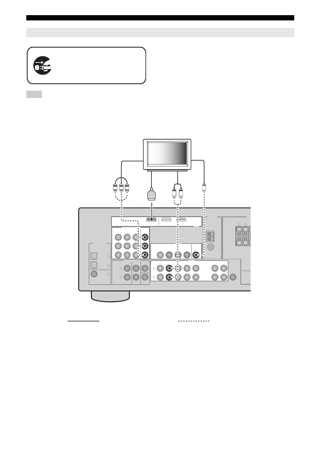
Connecting a TV monitor or projector
Make sure that this unit and other
components are unplugged from the
AC wall outlets.
LR
L
R
VIDEO
MULTI CH INPUT
DIGITAL INPUT
OUTPUT
ANTENNA
SP
1
2
3
DVD
DVD
COAXIAL
OPTICAL
CD
DTV/CBL
DTV/
CBL
SURROUND C
MONITOR
OUT
SUB
WOOFER
DVR
FRONT CENTER
SUBWOOFER
SURROUND
IN
OUT
AM
GND
FM
75
UNBAL.
HDMI
DVDOUT DTV/CBL
COMPONENT VIDEO
DVD DTV/CBL DVR
MONITOR
OUT
Y
P
R
P
B
V
P
R
P
B
Y
LR
MD/
CD-R
OUT
(REC)
IN
(PLAY)
L
R
AUDIO
DVD DTV/CBL DVR CD
IN
OUT
TV
(or projector)
Component
video in
Video
in
Audio
out
HDMI
in
Recommended connections Alternative connections
13 En
Connections
English
INTRODUCTION
ADDITIONAL
INFORMATION APPENDIX
PREPARATION
BASIC
OPERATION
ADVANCED
OPERATION
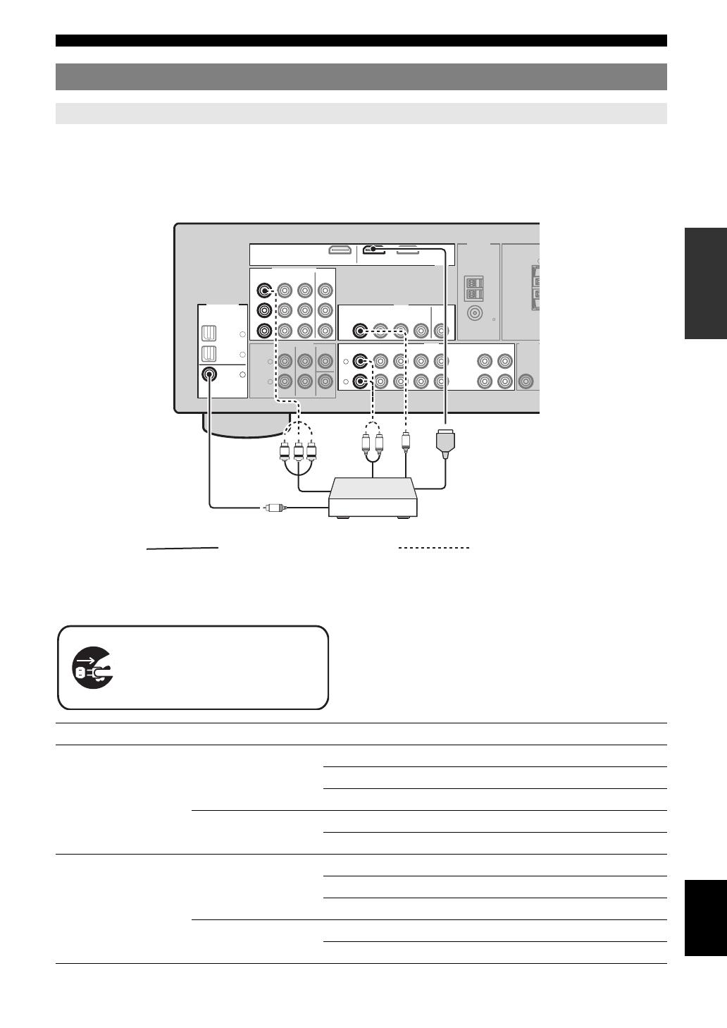
This unit has three types of audio jacks, two types of video jacks and HDMI jacks. You can choose the connection
method depending on the component to be connected.
■ Connecting example (connecting a DVD player)
■ Jacks used for audio and video connections
Recommended connections are indicated by (*). When connecting a recording component, you need to make additional
connections for recording (signal transmission from this unit to the recording component).
y
• You can also use the VIDEO AUX jacks (see page 14) on the front panel
to connect an additional component.
• To confirm the positions of “jacks on this unit” in the following table,
refer to “Rear panel” in “Functional overview” on page 6.
Connecting other components
Connecting audio and video components
L
R
L
R
COMPONENT VIDEO
HDMI
VIDEO
AUDIOMULTI CH INPUT
DIGITAL INPUT
OUTPUT
ANTENNA
1
2
3
DVD DTV/CBL DVR
DVD
DVD
COAXIAL
OPTICAL
CD
DTV/CBL
DTV/
CBL
DVDOUT DTV/CBL
S
MONITOR
OUT
MD/
CD-R
SUB
WOOFER
OUT
(REC)
IN
(PLAY)
DVR
DVD
FRONT CENTER
SUBWOOFER
SURROUND
DTV/CBL DVR CD
IN
OUT
IN
OUT
MONITOR
OUT
AM
GND
FM
75
UNBAL.
Y
P
R
P
B
P
R
P
B
Y
L
R
C
V
Component out
Audio out
Video out
Coaxial out
HDMI out
Recommended connections Alternative connections
Make sure that this unit and other
components are unplugged from the
AC wall outlets.
Component Signal type Jacks on component Jacks on this unit
DVD player or Blu-ray
Disc player
Video HDMI out* HDMI (DVD)*
Component out COMPONENT VIDEO (DVD)
Video out (composite) VIDEO (DVD)
Audio Optical out* COAXIAL (DVD)*
Audio out (analog) AUDIO (DVD)
Set-top box Video HDMI out* HDMI (DTV/CBL)*
Component out COMPONENT VIDEO (DTV/CBL)
Video out (composite) VIDEO (DTV/CBL)
Audio Optical out* OPTICAL (DTV/CBL)*
Analog out (analog) AUDIO (DTV/CBL)
14 En
Connections
Notes
• Be sure to make the same type of video connections as those made for your TV if the video conversion is disabled. For example, if you connected your
TV to the VIDEO MONITOR OUT jack of this unit, connect other components to the VIDEO jacks.
• Check the copyright laws in your country to record from CDs, radio, etc. Recording of copyrighted material may infringe copyright laws.
• To make a digital connection to a component other than the default one assigned to each DIGITAL INPUT or DIGITAL OUTPUT jack, configure the
“INPUT ASSIGN” setting (see page 34).
• Only analog audio signals output at AUDIO OUT (REC) jack can be recorded using the recording components. Therefore Digital signals input at the
DIGITAL INPUT jacks or analog signals input at MULTI CH IN jacks can be output at the analog AUDIO OUT (REC) jack for recording.
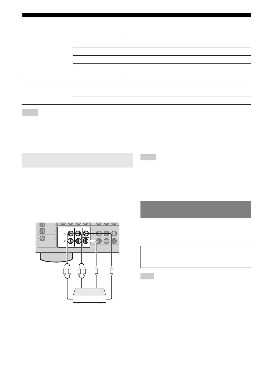
This unit is equipped with 6 additional input jacks
(FRONT L/R, SURROUND L/R, CENTER and
SUBWOOFER) for discrete multi-channel input from a
multi-format player, external decoder or sound processor.
Connect the output jacks on your multi-format player or
external decoder to the MULTI CH INPUT jacks. Be sure
to match the left and right output jacks to the left and right
input jacks for the front and surround channels.
Notes
• When you select the component connected to the MULTI CH INPUT
jacks as the input source (see page 19), this unit automatically turns off
the digital sound field processor, and you cannot select sound field
programs.
• This unit does not redirect signals input at the MULTI CH INPUT jacks
to accommodate for missing speakers. We recommend that you connect a
5.1-channel speaker system before using this feature.
• The source connected to the MULTI CH INPUT jacks on this unit cannot
be recorded.
Use the VIDEO AUX jacks on the front panel to connect a
game console or a video camera to this unit. To reproduce
the source signals input at these jacks, select “V-AUX” as
the input source.
Note
• The audio signals input at the PORTABLE mini jack take priority over
the ones input at the AUDIO L/R jacks.
DVD recorder Video HDMI out* HDMI (DVR)*
Video out (composite) VIDEO (DVR IN)
Audio Audio out (analog)* AUDIO (IN (PLAY))*
Audio recording Audio in (analog)* AUDIO (OUT (REC))*
Video recording Video in (composite)* VIDEO (DVR OUT)*
CD player Audio Coaxial out* OPTICAL (CD)*
Audio out (analog) AUDIO (CD)
MD or CD recorder Audio Audio out (analog)* AUDIO (IN (PLAY))*
Audio recording Audio in (analog)* AUDIO (OUT (REC))*
Component Signal type Jacks on component Jacks on this unit
Connecting a multi-format player or an
external decoder
L
R
L
R
MULTI CH INPUT
1
2
3
DVD
COAXIAL
CD
DTV/
CBL
DVD
FRONT CENTER
SUBWOOFER
SURROUND
DTV/CBL DV
IN
L
R
L
R
Front out
Surround out
Subwoofer out
Center out
Multi-format player or
external decoder
Using the VIDEO AUX jacks on the
front panel
Caution
Be sure to turn down the volume of this unit and other
components before making connections.
15 En
Connections
English
INTRODUCTION
ADDITIONAL
INFORMATION APPENDIX
PREPARATION
BASIC
OPERATION
ADVANCED
OPERATION
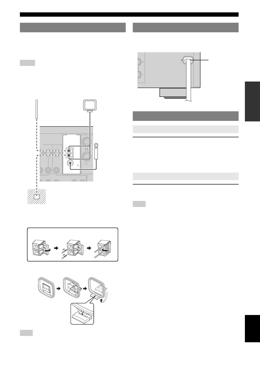
Both FM and AM indoor antennas are supplied with this
unit. In general, these antennas should provide sufficient
signal strength. Connect each antenna correctly to the
designated terminals.
Notes
• The AM loop antenna should be placed away from this unit.
• A properly installed outdoor antenna provides clearer reception than an
indoor one. If you experience poor reception quality, install an outdoor
antenna. Consult the nearest authorized Yamaha dealer or service center
about outdoor antennas.
• The AM loop antenna should always be connected, even if an outdoor
AM antenna is connected to this unit.
Connecting the wire of the AM loop antenna
Assembling the supplied AM loop antenna
Note
• The types of the supplied AM loop antenna is different depending on the
models.
Once all connections are complete, plug the power cable
into the AC wall outlet.
Press ASTANDBY/ON (or cPOWER) to turn on
this unit.
y
• When you turn on this unit, there will be a 4 to 5-second delay before this
unit can reproduce sound.
Press ASTANDBY/ON (or bSTANDBY) to turn
off this unit.
Note
• In the standby mode, this unit consumes a small amount of power in
order to receive infrared signals from the remote control.
Connecting the FM and AM antennas
EO
ANTENNA
R
SURR
AUDIO OUT
DVR
CD
N
OUT
DVR
AM
GND
FM
UNBAL.
75
N OUT
MONITOR
OUT
MD/
CD-R
OUT
(REC)
IN
(PLAY)
Outdoor AM antenna
Use a 5 to 10 m (16 to 32 ft)
of vinyl-covered wire
extended outdoors from a
window.
AM loop
antenna
(supplied)
Indoor FM
antenna
(supplied)
Ground
For maximum safety and minimum
interference, connect the antenna GND
terminal to a good earth ground. A good earth
ground is a metal stake driven into moist earth.
Open the
lever
Insert Close the
lever
Connecting the power cable
Turning on and off the power
Turning on this unit
Set this unit to the standby mode
Power cable
To the AC wall outlet
16 En
This unit has the Yamaha Parametric Acoustic Optimizer (YPAO). With the YPAO, this unit automatically adjusts output
characteristics of your speakers based on speaker positions, speaker performances, and acoustic characteristics of the
room. We recommend that you first adjust the output characteristics with the YPAO when you use this unit.
y
• Initial settings are indicated by (*) in the following each parameter.
1 Make sure of the following check points.
Before starting the automatic setup, check the
following check points.
• All speakers and subwoofer are connected
appropriately.
• Headphones are disconnected from this unit.
• This unit is turned on.
• The connected subwoofer is tuned on and the
volume level is set to about half way (or slightly
less).
• FRONT A speakers are selected as the front
speaker system (see page 19).
• The room is sufficiently quiet.
• The crossover frequency control of the connected
subwoofer is set to the maximum.
2 Connect the supplied optimizer microphone
to the OPTIMIZER MIC jack on the front
panel.
“SETUP•••••AUTO” appears on the front panel
display.
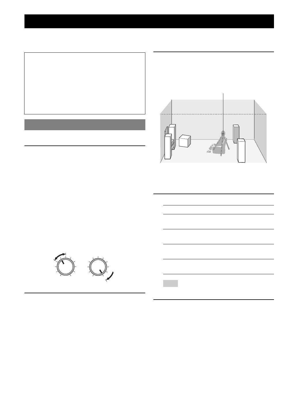
3 Place the optimizer microphone at your
normal listening position on a flat level
surface with the omni-directional
microphone heading upward.
y
• We recommend that you use a tripod (etc.) to affix the optimizer
microphone at the same height as your ears would be when you are
seated in your listening position. You can use the attached screw of
a tripod (etc.) to fix the optimizer microphone to the tripod (etc.).
4 Press ol / h to select “AUTO.”
Note
• “RELOAD” or “UNDO” is available only when you have
previously run “AUTO SETUP” and confirmed the results.
5 Press oENTER to start the setup
procedure.
This unit starts the automatic setup procedure. Loud
test tones are output from each speaker during the
audio setup procedure. After all settings
(“INITIALIZING,” “WIRING/LEVEL,”
“DISTANCE,” “SIZE”) are sequentially completed,
“FINISH” appears on the front panel display.
y
• To cancel the automatic setup, press ok.
Optimizing the speaker setting for your listening room (YPAO)
Notes
• Be advised that it is normal for loud test tones to be
output during the “AUTO SETUP” procedure. Do not
allow small children to enter the room during the
procedure.
• To achieve the best results, make sure that the room
is as quiet as possible while the “AUTO SETUP”
procedure is in progress. If there is too much ambient
noise, the results may not be satisfactory.
Using AUTO SETUP
VOLUME
MIN
MAX
MIN MAX
CROSSOVER
HIGH CUT
Controls of a subwoofer (example)
Choice Function
AUTO* Automatically runs the entire “AUTO
SETUP” procedure.
RELOAD Reloads the last “AUTO SETUP” settings and
overrides the previous settings.
UNDO Undoes the last “AUTO SETUP” settings and
restores the previous settings.
DEFAULT Resets the “AUTO SETUP” parameters to the
initial factory settings.
Optimizer microphone
1 HTR-6230AV R e ce ive rOWNER S MANUALUC aution-i En Explanation of Graphical SymbolsThe lightning flash with arrowhead symbol, within an equilateral triangle, is intended to alert you to the presence of uninsulated dangerous voltage within the product s enclosure that may be of sufficient magnitude to constitute a risk of electric shock to exclamation point within an equilateral triangle is intended to alert you to the presence of important operating and maintenance (servicing) instructions in the literature accompanying the Instructions All the safety and operating instructions should be read before the product is Instructions The safety and operating instructions should be retained for future Warnings All warnings on the product and in the operating instructions should be adhered Instructions All operating and use instructions should be Unplug this product from the wall outlet before cleaning.
2 Do not use liquid cleaners or aerosol Do not use attachments not recommended by the product manufacturer as they may cause and Moisture Do not use this product near water for example, near a bath tub, wash bowl, kitchen sink, or laundry tub; in a wet basement; or near a swimming pool; and the Do not place this product on an unstable cart, stand, tripod, bracket, or table. The product may fall, causing serious injury to a child or adult, and serious damage to the product. Use only with a cart, stand, tripod, bracket, or table recommended by the manufacturer, or sold with the product.
3 Any mounting of the product should follow the manufacturer s instructions, and should use a mounting accessory recommended by the product and cart combination should be moved with care. Quick stops, excessive force, and uneven surfaces may cause the product and cart combination to Slots and openings in the cabinet are provided for ventilation and to ensure reliable operation of the product and to protect it from overheating, and these openings must not be blocked or covered. The openings should never be blocked by placing the product on a bed, sofa, rug, or other similar surface.
4 This product should not be placed in a built-in installation such as a bookcase or rack unless proper ventilation is provided or the manufacturer s instructions have been adhered Sources This product should be operated only from the type of power source indicated on the marking label. If you are not sure of the type of power supply to your home, consult your product dealer or local power company. For products intended to operate from battery power, or other sources, refer to the operating or Polarization This product may be equipped with a polarized alternating current line plug (a plug having one blade wider than the other).
5 This plug will fit into the power outlet only one way. This is a safety feature. If you are unable to insert the plug fully into the outlet, try reversing the plug. If the plug should still fail to fit, contact your electrician to replace your obsolete outlet. Do not defeat the safety purpose of the polarized Protection Power-supply cords should be routed so that they are not likely to be walked on or pinched by items placed upon or against them, paying particular attention to cords at plugs, convenience receptacles, and the point where they exit from the For added protection for this product during a lightning storm, or when it is left unattended and unused for long periods of time, unplug it from the wall outlet and disconnect the antenna or cable system.
6 This will prevent damage to the product due to lightning and power-line Lines An outside antenna system should not be located in the vicinity of overhead power lines or other electric light or power circuits, or where it can fall into such power lines or circuits. When installing an outside antenna system, extreme care should be taken to keep from touching such power lines or circuits as contact with them might be Do not overload wall outlets, extension cords, or integral convenience receptacles as this can result in a risk of fire or electric and Liquid Entry Never push objects of any kind into this product through openings as they may touch dangerous voltage points or short-out parts that could result in a fire or electric shock.
7 Never spill liquid of any kind on the Do not attempt to service this product yourself as opening or removing covers may expose you to dangerous voltage or other hazards. Refer all servicing to qualified service Requiring Service Unplug this product from the wall outlet and refer servicing to qualified service personnel under the following conditions:a)When the power-supply cord or plug is damaged,b)If liquid has been spilled, or objects have fallen into the product,c)If the product has been exposed to rain or water,IMPORTANT SAFETY INSTRUCTIONSCAUTIONCAUTION: TO REDUCE THE RISK OF ELECTRIC SHOCK, DO NOT REMOVE COVER (OR BACK).
8 NO USER-SERVICEABLE PARTS INSIDE. REFER SERVICING TO QUALIFIED SERVICE OF ELECTRIC SHOCK DO NOT OPENC aution-ii EnIMPORTANT SAFETY INSTRUCTIONSd)If the product does not operate normally by following the operating instructions. Adjust only those controls that are covered by the operating instructions as an improper adjustment of other controls may result in damage and will often require extensive work by a qualified technician to restore the product to its normal operation,e)If the product has been dropped or damaged in any way, and f)
9 When the product exhibits a distinct change in performance — this indicates a need for Parts When replacement parts are required, be sure the service technician has used replacement parts specified by the manufacturer or have the same characteristics as the original part. Unauthorized substitutions may result in fire, electric shock, or other Check Upon completion of any service or repairs to this product, ask the service technician to perform safety checks to determine that the product is in proper operating or Ceiling Mounting The unit should be mounted to a wall or ceiling only as recommended by the The product should be situated away from heat sources such as radiators, heat registers, stoves, or other products (including amplifiers)
10 That produce Antenna Grounding If an outside antenna or cable system is connected to the product, be sure the antenna or cable system is grounded so as to provide some protection against voltage surges and built-up static charges. Article 810 of the National Electrical Code, ANSI/NFPA 70, provides information with regard to proper grounding of the mast and supporting structure, grounding of the lead-in wire to an antenna discharge unit, size of grounding conductors, location of antenna discharge unit, connection to grounding electrodes, and requirements for the grounding to CATV system installer.