-
Contents
-
Table of Contents
-
Bookmarks
Related Manuals for Briggs & Stratton 106200
Summary of Contents for Briggs & Stratton 106200
-
Page 1
REPAIR MANUAL 106200, 10R200, 10U200 SINGLE CYLINDER OHV AIR-COOLED ENGINES… -
Page 3
Foreword This manual was written to assist engine technicians and service personnel with the repair and maintenance procedures for Briggs & Stratton® engines. It assumes that persons using this manual have been properly trained in and are familiar with the servicing procedures for these products, including the proper use of required tools and safety equipment and the application of appropriate safety practices. -
Page 4
This engine repair manual includes the following engine models: • MODEL 106200 • MODEL 10R200 • MODEL 10U200 NOTICE Models 10R200 and 10U200 have limited service parts. Review the parts list for part availability before conducting any service work. -
Page 5
SECTION 1 – GENERAL INFORMATION SECTION 2 – SAFETY, MAINTENANCE AND ADJUSTMENTS SECTION 3 – TROUBLESHOOTING SECTION 4 – FUEL SYSTEM AND CARBURETION SECTION 5 – CONTROLS AND GOVERNOR SYSTEM SECTION 6 – LUBRICATION SYSTEM SECTION 7 – CYLINDER HEAD AND VALVES SECTION 8 –… -
Page 7
SECTION 1 – GENERAL INFORMATION GENERAL INFORMATION — — — — — — — — — — — — — — — — — — — — — — — — — — — — — — — — — — — — — — — — — — — — — — — — — — — — — — — — — — — — — — — — — 4 Engine Identification — — — — — — — — — — — — — — — — — — — — — — — — — — — — — — — — — — — — — — — — — — — — — — — — — — — — — — — — — — — — — — — — — — — 4 Acronyms, Abbreviations and Meanings — — — — — — — — — — — — — — — — — — — — — — — — — — — — — — — — — — — — — — — — — — — — — — — — — — — — — 4 Order of Engine Assembly and Disassembly — — — — — — — — — — — — — — — — — — — — — — — — — — — — — — — — — — — — — — — — — — — — — — — — — — 4… -
Page 8
GENERAL INFORMATION Order of Disassembly Section Section Procedure Engine Identification Number Engine identification is located at (A) or (B) as shown. Control panel trim Remove Control Bracket Governor control bracket Remove Control Bracket Air cleaner base Remove Control Bracket Carburetor Remove Carburetor Disassemble carburetor Disassemble Carburetor… -
Page 9
Order of Assembly Section Section Procedure Number Rocker arms Install Cylinder Head Adjust valve clearance Adjust Valve Clearance Rocker cover / breather Install Breather Cylinder shield Install Cylinder Head Flywheel Install Flywheel Armature Install Flywheel Adjust armature air gap Adjust Armature Air Gap Blower housing Adjust Armature Air Gap Rewind starter… -
Page 10
BRIGGSandSTRATTON.COM… -
Page 11: Table Of Contents
In-Tank Fuel Filter (Models 106200 and 10U200) — — — — — — — — — — — — — — — — — — — — — — — — — — — — — — — — -…
-
Page 12
Adjust Valve Clearance — — — — — — — — — — — — — — — — — — — — — — — — — — — — — — — — — — — — — — — — — — — — — — — — — — — — — — — — — — — — — — — — 25 BRIGGSandSTRATTON.COM… -
Page 13: Safety Information
SAFETY INFORMATION This repair manual contains safety information that is Symbol Meaning Symbol Meaning designed to: Amputation hazard — entanglement • Make you aware of hazards associated with engines. • Inform you of the risk of injury associated with those hazards.
-
Page 14
be empty or fuel can leak out and result in a fire or explosion. WARNING When Transporting Equipment The engine exhaust from this product contains chemicals known to the State of California to cause cancer, birth • Transport/move/repair with fuel tank EMPTY or with defects, or other reproductive harm. -
Page 15
Before performing adjustments or repairs: WARNING • Disconnect the spark plug wire and keep it away from Starter cord kickback (rapid retraction) will pull hand and the spark plug. arm toward engine faster than you can let go which could cause broken bones, fractures, bruises, or sprains •… -
Page 16: Engine Maintenance
This engine is certified to operate on gasoline. The emissions control system for this engine is EM (Engine Modifications). In-Tank Fuel Filter (Models 106200 and 10U200) 1. Drain fuel tank by running engine until fuel tank is High Altitude empty.
-
Page 17: In-Line Fuel Filter (Models 106200 And 10U200)
9. Install cleaned or new fuel filter and O-ring into fuel tank. Torque fuel filter to the value listed in Section 13 In-Line Fuel Filter (Models 106200 and 10U200) — Engine Specifications . 1. Drain fuel tank by running engine until fuel tank is Note: Make sure o-ring is seated in groove of fuel filter.
-
Page 18: Change Oil
1. Disconnect spark plug wire from spark plug. Secure • If you drain the oil from the oil fill hole (not spark plug wire away from spark plug. recommended), the fuel tank must be empty or fuel can leak out and result in a fire or explosion. 2.
-
Page 19: Change Air Filter
• Never start or run the engine with the air cleaner assembly or the air filter removed. NOTICE Do not use pressurized air or solvents to clean the filter. Pressurized air can damage the filter and solvents will dissolve the filter. The air filter system uses either a Dual Element Oval, Oil Bath, Foam Low Mount or Foam Large Panel filter.
-
Page 20: Oil Bath Air Filter
and void your warranty. If oil or debris enters the carburetor elbow, wipe with a clean dry cloth. 11. Install retainer (E) and O-ring (F) into the bowl (D). 12. Install foam filter (C) into cover (B). 13. Install air cleaner cover (B) and secure using washer and knob (A).
-
Page 21: Foam Large Panel Air Filter
6. Install air cleaner cover (B) and secure with two fasteners (A). Do not over-tighten. Foam Large Panel Air Filter Service Spark Plug 1. Open two fastening clips (A), and then remove air NOTICE Spark plugs have different thread lengths and cleaner cover (B) and foam filter (C).
-
Page 22: Clean Air Cooling System
5. Install spark plug by hand and tighten finger tight. Then torque to the value listed in Section 13 — Engine Specifications. 6. Connect the spark plug wire. Clean Air Cooling System WARNING Running engines produce heat. Engine parts, especially muffler, become extremely hot.
-
Page 23: Storage
There is no need to drain gasoline from the engine if a fuel Storage stabilizer is added according to instructions. Run the engine for 2 minutes to circulate the stabilizer throughout the fuel Fuel can become stale when stored over 30 days. Stale system before storage.
-
Page 24: Engine Adjustments
2. If equipped, remove two screws (B) and then remove away from engine to gain access to the stop switch wire connections. control panel trim (C) from engine. 3. 106200 engine: Remove screws (F) and then remove rewind starter assembly (G) from blower housing (E). BRIGGSandSTRATTON.COM…
-
Page 25
14. Loosen screw (N). Press armature legs (P) tight against flywheel. 106200 engine: Mark each wire on stop switch for reassembly and then disconnect wires from stop switch. A. Top Terminal (H) — Red ground wire B. -
Page 26: Carburetor
(B). Torque screws to the value listed 18. 106200 engine: Connect stop switch wires to the same in Section 13 — Engine Specifications . terminals as removed from.
-
Page 27: Remote Choke And Throttle Controls
Adjust Remote Throttle Control — Control Bracket Mounted There are two locations on the control bracket that the remote cable can be mounted. Refer to the following illustration. Remote Choke and Throttle Controls 1. Remove air cleaner cover and air filter as instructed in Adjust Remote Choke Control — Carb Mounted Change Air Filter found in this section.
-
Page 28: Remote Throttle Control — Carburetor Mounted
Note: Each time the governor lever is removed, it must be replaced with a new governor lever. 7. Install nut (B) and screw from the previous step onto a new governor lever. Slide the new governor lever onto the governor shaft. 8.
-
Page 29
2. Remove the four rocker cover screws and remove the rocker cover. Dealers — www.thepowerportal.com 3. Turn crankshaft clockwise (J) (flywheel end) until piston (H) is at top dead center on the compression stroke. Consumers — Please contact your local Briggs & 4. -
Page 30
BRIGGSandSTRATTON.COM… -
Page 31
SECTION 3 – TROUBLESHOOTING SYSTEMIC CHECK — — — — — — — — — — — — — — — — — — — — — — — — — — — — — — — — — — — — — — — — — — — — — — — — — — — — — — — — — — — — — — — — — — — — — — 28 Check Ignition — — — — — — — — — — — — — — — — — — — — — — — — — — — — — — — — — — — — — — — — — — — — — — — — — — — — — — — — — — — — — — — — — — — — — — — 28 Check Carburetion — — — — — — — — — — — — — — — — — — — — — — — — — — — — — — — — — — — — — — — — — — — — — — — — — — — — — — — — — — — — — — — — — — — — 29 Check Compression — — — — — — — — — — — — — — — — — — — — — — — — — — — — — — — — — — — — — — — — — — — — — — — — — — — — — — — — — — — — — — — — — — — 29… -
Page 32: Systemic Check
SYSTEMIC CHECK Most complaints concerning engine operation can be classified as one or a combination of the following: Check Ignition • Will not start Engine Stopped • Hard starting With spark plug installed, connect Ignition Tester #19368 • Lack of power to spark plug lead and connect ground wire to a good •…
-
Page 33: Check Carburetion
• Shorted equipment or engine stop switch wire the spark plug hole. Replace the plug. If the engine fires a few times and then stops, look for the same conditions as • Incorrect armature air gap for a dry plug. •…
-
Page 34: Electrical Systems
ELECTRICAL SYSTEMS Starter Motor Test Fixture Equipment Used for Testing A starter motor test fixture may be made from 1/4” (6 mm) Note: Not all testing equipment shown is used on every steel stock. engine model. 1. Drill two 3/8” (10 mm) holes for starter mounting bracket Digital Multimeter (B).
-
Page 35
3. Rotate selector to (Ohms) position. 4. Insert RED test lead into the V Ω receptacle in the meter. 5. Insert BLACK test lead into COM receptacle. 6. Connect either test lead to sensor wire. 7. Connect other test lead to base of cylinder. If meter reads «near zero»… -
Page 36
BRIGGSandSTRATTON.COM… -
Page 37
SECTION 4 – FUEL SYSTEM AND CARBURETION FUEL TANK — — — — — — — — — — — — — — — — — — — — — — — — — — — — — — — — — — — — — — — — — — — — — — — — — — — — — — — — — — — — — — — — — — — — — — — — — — — 34 Remove Fuel Tank — — — — — — — — — — — — — — — — — — — — — — — — — — — — — — — — — — — — — — — — — — — — — — — — — — — — — — — — — — — — — — — — — — — 35 Inspect Fuel Tank — — — — — — — — — — — — — — — — — — — — — — — — — — — — — — — — — — — — — — — — — — — — — — — — — — — — — — — — — — — — — — — — — — — — 35 Install Fuel Tank — — — — — — — — — — — — — — — — — — — — — — — — — — — — — — — — — — — — — — — — — — — — — — — — — — — — — — — — — — — — — — — — — — — — — 35… -
Page 38: Fuel Tank
FUEL TANK BRIGGSandSTRATTON.COM…
-
Page 39: Remove Fuel Tank
Remove Fuel Tank WARNING Fuel and its vapors are extremely flammable and 1. Drain fuel tank (B) by running engine until fuel tank is explosive. empty. Fire or explosion can cause severe burns or death. 2. Disconnect spark plug wire from spark plug (N). Secure spark plug wire away from spark plug.
-
Page 40
2. Install fuel line (E) with clamp (F) onto in-tank fuel filter 5. Install the air filter (K) and air cleaner cover (J). For (D) or fuel tank fitting (in-line fuel filter applications). detailed instructions and air cleaner variations, refer to Change Air Filter found in Section 2. -
Page 41: Carburetor
CARBURETOR…
-
Page 42: Carburetor And Carburetor Overhaul Kit
2. Remove bowl nut (Z) and metal or fiber washer (Y) and Carburetor and Carburetor Overhaul Kit then remove the bowl (V) and rubber gasket (U). Discard the fiber washer (if equipped), and rubber Consult the Illustrated Parts List for the correct carburetor gasket.
-
Page 43: Install Carburetor
4. Install float and then install the float hinge pin (T). 5. Install control bracket (F) and air cleaner base (E) as instructed in Install Control Bracket found in Section 5. 5. Install new rubber gasket (U), bowl (V), old metal or new fiber washer (Y) and bowl nut (Z).
-
Page 44
BRIGGSandSTRATTON.COM… -
Page 45
SECTION 5 – CONTROLS AND GOVERNOR SYSTEM CONTROL BRACKET — — — — — — — — — — — — — — — — — — — — — — — — — — — — — — — — — — — — — — — — — — — — — — — — — — — — — — — — — — — — — — — — — — — — 42 Remove Control Bracket — — — — — — — — — — — — — — — — — — — — — — — — — — — — — — — — — — — — — — — — — — — — — — — — — — — — — — — — — — — — — — — 43 Install Control Bracket — — — — — — — — — — — — — — — — — — — — — — — — — — — — — — — — — — — — — — — — — — — — — — — — — — — — — — — — — — — — — — — — — 43 GOVERNOR SYSTEM — — — — — — — — — — — — — — — — — — — — — — — — — — — — — — — — — — — — — — — — — — — — — — — — — — — — — — — — — — — — — — — — — — — — 44… -
Page 46: Control Bracket
CONTROL BRACKET BRIGGSandSTRATTON.COM…
-
Page 47: Remove Control Bracket
2. Install control bracket using two screws (J) and (K). 2. Remove air cleaner cover and air filter (B) as instructed Install ground wire under screw (K), (106200 engine in Change Air Filter found in Section 2. only). Torque screws to the value listed in Section 13 3.
-
Page 48: Governor System
GOVERNOR SYSTEM BRIGGSandSTRATTON.COM…
-
Page 49: Top No-Load Speed
Be sure to note orientation of linkages and springs (N) 4. Check governor gear (R) for chipped or damaged teeth. before removing. Note: If the governor gear assembly is damaged, the engine must be replaced. There are no replacement parts available. Top No-Load Speed Briggs &…
-
Page 50
BRIGGSandSTRATTON.COM… -
Page 51
SECTION 6 – LUBRICATION SYSTEM BREATHER AND LUBRICATION SYSTEM — — — — — — — — — — — — — — — — — — — — — — — — — — — — — — — — — — — — — — — — — — — — — — — — — — — — — 48 Breathers — — — — — — — — — — — — — — — — — — — — — — — — — — — — — — — — — — — — — — — — — — — — — — — — — — — — — — — — — — — — — — — — — — — — — — — — — — 49 Service Breather — — — — — — — — — — — — — — — — — — — — — — — — — — — — — — — — — — — — — — — — — — — — — — — — — — — — — — — — — — — — — — — — — — 49 Lubrication System — — — — — — — — — — — — — — — — — — — — — — — — — — — — — — — — — — — — — — — — — — — — — — — — — — — — — — — — — — — — — — — — — — — 49… -
Page 52: Breather And Lubrication System
BREATHER AND LUBRICATION SYSTEM BRIGGSandSTRATTON.COM…
-
Page 53: Breathers
3. If air flow is restricted under vacuum at the breather Breathers hose, or has no resistance when blowing on the breather hose, replace the rocker cover. Briggs & Stratton engines utilize a breather valve (C) to control and maintain cylinder vacuum. The breather valve is a fiber disc or reed which closes on the piston up stroke Install Breather and opens on the piston down stroke.
-
Page 54: Low Oil Sensor System
LOW OIL SENSOR SYSTEM BRIGGSandSTRATTON.COM…
-
Page 55: Low Oil Sensor System
2. Rotate oil sensor fitting back and forth to make sure Low Oil Sensor System rubber washer is seated against cylinder housing. Install nut (U) onto oil sensor fitting and torque to the value The Low Oil Sensor System consists of: listed in Section 13 — Engine Specifications .
-
Page 56
BRIGGSandSTRATTON.COM… -
Page 57
SECTION 7 – CYLINDER HEAD AND VALVES CYLINDER HEAD AND VALVES — — — — — — — — — — — — — — — — — — — — — — — — — — — — — — — — — — — — — — — — — — — — — — — — — — — — — — — — — — — — 54 Remove Cylinder Head — — — — — — — — — — — — — — — — — — — — — — — — — — — — — — — — — — — — — — — — — — — — — — — — — — — — — — — — — — — — — — — — 55 Disassemble Cylinder Head — — — — — — — — — — — — — — — — — — — — — — — — — — — — — — — — — — — — — — — — — — — — — — — — — — — — — — — — — — — — — 55 Inspect Cylinder Head — — — — — — — — — — — — — — — — — — — — — — — — — — — — — — — — — — — — — — — — — — — — — — — — — — — — — — — — — — — — — — — — — 55… -
Page 58: Cylinder Head And Valves
CYLINDER HEAD AND VALVES BRIGGSandSTRATTON.COM…
-
Page 59: Remove Cylinder Head
Note: Refer to the following illustrations and the exploded Remove Cylinder Head view at the beginning of this section. 1. Remove four screws (H) from rocker cover (J), then remove cover and gasket (K). 2. Remove three screws (AA), (AC) and (AD) from cylinder head shield (AB).
-
Page 60: Assemble Cylinder Head
2. If head passes visual inspection, check valve guides for wear. If valve guides meet or exceed the reject dimension shown in Section 13 — Engine Specifications , replace the cylinder head. 3. Inspect valves for wear or damage. If slight wear is found, lap the valve and seat as instructed in the following steps.
-
Page 61: Install Cylinder Head
6. 10U200 engine only – Install valve cap (M) onto end of exhaust valve stem (Q). 106200 and 10R200 engines only – Install valve cap (M) onto end of intake and exhaust valve stems (Q).
-
Page 62
BRIGGSandSTRATTON.COM… -
Page 63
SECTION 8 – PISTON, RINGS AND CONNECTING ROD PISTON, RINGS AND CONNECTING ROD — — — — — — — — — — — — — — — — — — — — — — — — — — — — — — — — — — — — — — — — — — — — — — — — — — — — — 60 Remove Piston and Connecting Rod — — — — — — — — — — — — — — — — — — — — — — — — — — — — — — — — — — — — — — — — — — — — — — — — — — — — — — — 61 Disassemble Piston and Connecting Rod — — — — — — — — — — — — — — — — — — — — — — — — — — — — — — — — — — — — — — — — — — — — — — — — — — — — 61 Inspect Piston and Pin — — — — — — — — — — — — — — — — — — — — — — — — — — — — — — — — — — — — — — — — — — — — — — — — — — — — — — — — — — — — — — — — — 61… -
Page 64: Piston, Rings And Connecting Rod
PISTON, RINGS AND CONNECTING ROD BRIGGSandSTRATTON.COM…
-
Page 65: Remove Piston And Connecting Rod
Remove Piston and Connecting Rod 1. Carefully remove any carbon or ridge at top of cylinder bore to prevent ring breakage. 4. Remove the bottom oil control ring (M) by hand as follows: 2. Remove rod bolts (G) and connecting rod cap (H). •…
-
Page 66: Check Ring End Gap
2. Using a dial caliper or plug gauge, measure the pin bore diameter. Compare with reject dimensions listed in Section 13 — Engine Specifications . If pin bore exceeds reject dimensions, replace the piston. 3. Measure outside diameter of pin (R) and compare to the reject dimension listed in Section 13 — Engine Specifications .
-
Page 67: Assemble Piston And Connecting Rod
Assemble Piston and Connecting Rod 1. Install a new piston pin retainer (Q) into one groove in piston bore (K). 2. Oil the piston pin bore (K), connecting rod pin bore (J), and the pin (R). Insert rod into piston, then slide pin through piston and rod bores until it seats against the retainer.
-
Page 68
NOTICE Apply steady pressure to piston until fully installed in cylinder bore. If piston sticks, do not pound or hammer on the piston crown. Loosen ring compressor and repeat procedure. 5. Cap should snap into position when assembled correctly. Install rod screws (G). 6. -
Page 69
SECTION 9 – CRANKSHAFT, CAMSHAFT AND FLYWHEEL FLYWHEEL — — — — — — — — — — — — — — — — — — — — — — — — — — — — — — — — — — — — — — — — — — — — — — — — — — — — — — — — — — — — — — — — — — — — — — — — — — — 66 Remove Flywheel — — — — — — — — — — — — — — — — — — — — — — — — — — — — — — — — — — — — — — — — — — — — — — — — — — — — — — — — — — — — — — — — — — — — 67 Inspect Flywheel — — — — — — — — — — — — — — — — — — — — — — — — — — — — — — — — — — — — — — — — — — — — — — — — — — — — — — — — — — — — — — — — — — — — — 67 Install Flywheel — — — — — — — — — — — — — — — — — — — — — — — — — — — — — — — — — — — — — — — — — — — — — — — — — — — — — — — — — — — — — — — — — — — — — — 67… -
Page 70: Flywheel
FLYWHEEL BRIGGSandSTRATTON.COM…
-
Page 71: Remove Flywheel
Remove Flywheel Inspect Flywheel Inspect flywheel key (A) for partial or complete sheering. 1. Remove blower housing (J) as instructed in Adjust Armature Air Gap found in Section 2. Inspect flywheel (E) for cracks, burrs on taper or keyway 2. Remove flywheel guard (B). and distortion of keyway.
-
Page 72: Crankshaft And Camshaft
CRANKSHAFT AND CAMSHAFT BRIGGSandSTRATTON.COM…
-
Page 73: Remove Crankshaft And Camshaft
Specifications . If wear exceeds the reject dimensions, Remove Crankshaft and Camshaft replace the camshaft. 1. Remove spark plug wire from the spark plug and then Install Crankshaft and Camshaft remove the spark plug. 2. Drain oil from engine and all fuel from fuel tank. 1.
-
Page 74: Check And Adjust Crankshaft End Play
11. Install spark plug by hand and tighten finger tight. Then torque to the value listed in Section 13 — Engine Specifications. 12. Connect the spark plug wire. 13. Adjust governor system as instructed in Governor found in Section 2. Check and Adjust Crankshaft End Play When crankcase cover (D) is installed with a standard gasket (C), end play should match values listed in Section…
-
Page 75
SECTION 10 – CYLINDER AND CRANKCASE COVER CYLINDER AND CRANKCASE COVER — — — — — — — — — — — — — — — — — — — — — — — — — — — — — — — — — — — — — — — — — — — — — — — — — — — — — — — 72 Cylinder — — — — — — — — — — — — — — — — — — — — — — — — — — — — — — — — — — — — — — — — — — — — — — — — — — — — — — — — — — — — — — — — — — — — — — — — — — — 73 Inspect and Measure Cylinder — — — — — — — — — — — — — — — — — — — — — — — — — — — — — — — — — — — — — — — — — — — — — — — — — — — — — — — — — 73 Recondition Cylinder Bore — — — — — — — — — — — — — — — — — — — — — — — — — — — — — — — — — — — — — — — — — — — — — — — — — — — — — — — — — — — 73… -
Page 76: Cylinder And Crankcase Cover
CYLINDER AND CRANKCASE COVER BRIGGSandSTRATTON.COM…
-
Page 77: Cylinder
Cylinder Inspect and Measure Cylinder 1. Using a plastic scraper, remove all traces of head gasket and cover gasket material. • Visually check cylinder for cracks, stripped threads, and bore damage. Bore damage, if not severe, may be corrected by reconditioning or resizing. •…
-
Page 78: Resize Cylinder Bore
4. Repeat washing and rinsing until all traces of honing grit are gone. Note: Honing grit is highly abrasive and will cause rapid wear to all of the internal components of the engine. When cylinder and cylinder housing has been thoroughly cleaned, use a clean white rag to wipe the cylinder bore and internal cylinder housing surfaces.
-
Page 79: Install Mag Bearing
6. Install new oil seal (J). Press oil seal past flush to the following dimension (K). Dimension K (Models 106200 and 10R200) = 0.060 ± 0.010 in. (1.50 ± 0.25 mm) Dimension K (Model 10U200) = 0.065 ± 0.006 in. (1.65 ±…
-
Page 80: Clean Cover
2. Visually inspect cover for cracks, stripped threads, and wear in bearing surfaces. If damage is found, replace the cover. Clean Cover 1. Wash the cover thoroughly with kerosene or other commercial solvent to remove oil sludge and residues. PTO Bearing Inspect PTO Bearing Ball bearing must rotate freely.
-
Page 81
6. Install new oil seal (B). Press oil seal past flush to the following dimension (L). Dimension L (Models 106200 and 10R200) = 0.167 ± 0.010 in. (4.25 ± 0.25 mm) Dimension L (Model 10U200) = 0.124 ± 0.006 in. (3.15… -
Page 82
BRIGGSandSTRATTON.COM… -
Page 83
SECTION 11 – STARTER REWIND STARTER — — — — — — — — — — — — — — — — — — — — — — — — — — — — — — — — — — — — — — — — — — — — — — — — — — — — — — — — — — — — — — — — — — — — — — 80 Remove Rewind Starter — — — — — — — — — — — — — — — — — — — — — — — — — — — — — — — — — — — — — — — — — — — — — — — — — — — — — — — — — — — — — — — — 81 Inspect Rewind Starter — — — — — — — — — — — — — — — — — — — — — — — — — — — — — — — — — — — — — — — — — — — — — — — — — — — — — — — — — — — — — — — — — 81 Replace Rewind Starter Rope — — — — — — — — — — — — — — — — — — — — — — — — — — — — — — — — — — — — — — — — — — — — — — — — — — — — — — — — — — — — 81… -
Page 84
REWIND STARTER BRIGGSandSTRATTON.COM… -
Page 85
2. Rotate rewind pulley clockwise to line up holes of pulley Remove Rewind Starter (G) and rope eyelet (F) and secure pulley assembly with a screwdriver (J) to prevent it from spinning. 1. Remove screws (E) and then remove rewind starter assembly (B) from blower housing (A). -
Page 86
6. Insert the other end of rope into handle (C) and tie a knot (L) to secure it. Fit knot into opening of handle. 7. Hold rope (D) firmly while removing screwdriver (J). Then slowly allow rope to rewind itself on pulley. Install Rewind Starter 1. -
Page 87
SECTION 12 – EXHAUST SYSTEM EXHAUST SYSTEM — — — — — — — — — — — — — — — — — — — — — — — — — — — — — — — — — — — — — — — — — — — — — — — — — — — — — — — — — — — — — — — — — — — — — 84 Exhaust System Warnings — — — — — — — — — — — — — — — — — — — — — — — — — — — — — — — — — — — — — — — — — — — — — — — — — — — — — — — — — — — — — — 85 OEM Statement — — — — — — — — — — — — — — — — — — — — — — — — — — — — — — — — — — — — — — — — — — — — — — — — — — — — — — — — — — — — — — — — — — — — — — 85 Inspect Exhaust System — — — — — — — — — — — — — — — — — — — — — — — — — — — — — — — — — — — — — — — — — — — — — — — — — — — — — — — — — — — — — — — — 85… -
Page 88
EXHAUST SYSTEM BRIGGSandSTRATTON.COM… -
Page 89
Exhaust System Warnings Muffler Deflector Remove Muffler Deflector WARNING 1. Prior to removing the muffler deflector, note its Running engines produce heat. Engine parts, especially orientation for reinstallation. mufflers, become extremely hot. Note: Orientation of muffler deflector should match the Severe thermal burns can occur on contact. -
Page 90
5. Install two nuts (Q) and lock washers (P) and torque to Inspect Spark Arrester value listed in Section 13 — Engine Specifications . 6. Install muffler guard (B) using screws (A). Torque Inspect spark arrester monthly or every 50 hours. screws to the value listed in Section 13 — Engine 1. -
Page 91
Specifications —… -
Page 92
SPECIFICATIONS Specifications — Models 106200 and 10R200 ENGINE SPECIFICATIONS Armature Air Gap 0.008 — 0.016 in (0,20 — 0,41 mm) Bore 2.68 in (68,00 mm) Compression Ratio Crankshaft End Play 0.003 — 0.030 in (0,09 — 0,75 mm) Displacement 9.95 ci (163 cc) Fuel Tank Capacity 3.2 qt (3,1 L) -
Page 93
Middle Ring End Gap 0.017 in (0,43 mm) 0.047 in (1,19 mm) Oil Ring End Gap 0.018 in (0,45 mm) 0.053 in (1,34 mm) Top Ring Land Clearance * 0.002 in (0,05 mm) 0.009 in (0,23 mm) STARTER ROPE Model 106200… -
Page 94
REJECT DIMENSIONS STANDARD SIZE REJECT SIZE Rope Size 0.177 in (4,5 mm) Rope Length 54.00, 102.00 in (1,37 / 2,59 m) Rope Size 0.157 in (4,0 mm) Rope Length 85.00 in (2,16 m) Model 10R200 Rope Size 0.157 in (4,0 mm) Rope Length 45.00 in (1,14 m) * Only Top Ring Land Clearance needs to be checked. -
Page 95
Specifications — Model 10U200 ENGINE SPECIFICATIONS Armature Air Gap 0.008 — 0.016 in (0,20 — 0,41 mm) Bore 2.68 in (68,00 mm) Compression Ratio 8.5:1 Crankshaft End Play 0.002 — 0.013 in (0,05 — 0,33 mm) Displacement 9.95 ci (163 cc) Fuel Tank Capacity 3.2 qt (3 L) Ignition Timing… -
Page 96
FASTENER TORQUE SPECIFICATIONS TORQUE Spark Plug 19 — 26 lb-ft (26 — 36 N-m) Stator (to Cylinder), AC Option 70 — 120 lb-in (8 — 14 N-m) REJECT DIMENSIONS STANDARD SIZE REJECT SIZE CYLINDER Mag Bearing Camshaft Bearing 0.551 in (14,00 mm) 0.553 in (14,05 mm) Bore Out-Of-Round 0.002 in (0,04 mm) -
Page 97
This page is intentionally left blank. -
Page 98
This page is intentionally left blank. BRIGGSandSTRATTON.COM… -
Page 99
This page is intentionally left blank. -
Page 100
Quality Starts With A Master Service Technician Part No. 381570EN (Rev -) BRIGGS&STRATTON POST OFFICE BOX 702 CORPORATION MILWAUKEE, WI 53201 USA 414 259 5333 BRIGGSandSTRATTON.COM ©2016 Briggs & Stratton Corporation…
Как научиться ремонтировать двигатели малого объема

Научиться ремонтировать свой собственный двигатель малого объема проще, чем вы думаете. Существует много простых шагов по устранению неисправностей и регулярному техническому обслуживанию, которые позволят вам сохранить вашу газонокосилку и другое наружное силовое оборудование в течение долгих лет. В случае больших проектов, вы всегда можете обратиться к местному дилеру двигателей малого объема для получения профессиональной помощи. Также всегда обращайтесь к руководству оператора , прежде чем предпринимать какие-либо действия для ремонта вашего двигателя.
Начало
Для тех, кто впервые ремонтирует двигатель малого объема, лучшим ресурсом является руководство. Содержащаяся в нем подробная информация должна решить большинство проблем с вашим двигателем малого объема. Затем проверьте множество ресурсов на веб-сайте Briggs & Stratton, которые дополняют часто задаваемые вопросы и полезное видео.
Покупайте правильные запчасти для ремонта
Обязательно покупайте оригинальные запчасти Briggs & Stratton, которые можно найти в нашем онлайн-магазине и у авторизованного дилера. Эти детали гарантированно подойдут для вашего двигателя. Обратитесь к руководству оператора вашего двигателя, чтобы узнать о правильном наборе деталей для вашего двигателя.
Непрерывное обучение
Лучший способ научиться ремонтировать двигатели малого объема — быть хорошим владельцем и следовать руководству. Для получения дополнительной информации о двигателях малого объема также можно обратиться к множеству небольших книг по ремонту двигателей и полезным видеороликам, предоставляемых сертифицированными механиками и авторами.
Руководство по ремонту
Раздел 1 Общие сведения
File001 (1).pdf
Раздел 2 Зажигание
File002.pdf
Раздел 3 Карбюрация
File003.pdf
Раздел 4 Органы управления, тяги карбюратора и тормоз маховика
File004.pdf
Раздел 5 Регуляторы скорости
File005.pdf
Раздел 6 Компрессия
File006.pdf
Раздел 7-1 Стартеры с обратной обмоткой (ручные стартеры)
File007.pdf
Раздел 7-2 Электростартеры
File008.pdf
Раздел 7-3 Генераторы
File009.pdf
Раздел 8 Смазка
File010.pdf
Раздел 9 Поршни кольца шатуны
File011.pdf
Раздел 10 Коленчатые валы, кулачковые валы и шестерёнчатые редукторы
File012.pdf
Раздел 11 цилиндры и подшипники
File013.pdf
Раздел 12 Системы балансировки
File014.pdf
Раздел 13 Глушители
File015.pdf
Раздел 14 технические данные одноцилиндровых двигателей
File016.pdf
7,86 Мб
Руководство по ремонту двигателей Briggs and Stratton
Формат: pdf
-
Год:
2007
-
Страниц:
281
-
Язык:
английский
-
Размер:
7,86 Мб
-
Категории:
Двигатели Briggs and Stratton
0,3 Мб
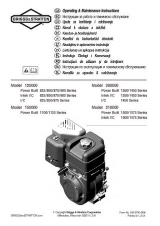
Двигатели Briggs and Stratton 120000 / 150000 / 200000 /
Формат: djvu
-
Год:
2009
-
Страниц:
11
-
Язык:
русский
-
Размер:
0,3 Мб
-
Категории:
Двигатели Briggs and Stratton
-
Contents
-
Table of Contents
-
Bookmarks
Quick Links
Repair Manuals for other
Briggs & Stratton Engines:
277527 Single Cylinder DOV
Air-Cooled Engines
®
273521 Twin Cylinder OHV Air-Cooled Engines
276781 Single Cylinder OHV Air-Cooled Engines
271172 Twin Cylinder «L» Head Air-Cooled Engines
270962 Single Cylinder «L» Head Air-Cooled Engines
276535 Two-Cycle Snow Engines
CE8069 Out of Production Engines (1919-1981)
Quality Starts With A
Master Service Technician
www.thePowerPortal.com (Dealers)
bRiGGsandstRattoN.coM (consumers)
BRIGGS&STRATTON
coRPoRatioN
Part No. 279000 — 3/11
Post office box 702
Milwaukee, wi 53201 usa
©2011 Briggs & Stratton Corporation
110000/120000 Professional Series
Service, Troubleshooting, and Repair Manual
Single Cylinder Engines
™
Chapters