![]()
4-я Красноармейская, 2А
Санкт-Петербург, 190005
Email: info@lenmoto.ru
Телефон: +7 (921) 930-81-18
Телефон: +7 (911) 928-08-06
Компания ЛенМото
Запчасти, аксессуары, экипировка, тюнинг для мотоциклов, скутеров, квадроциклов, снегоходов, багги, гидроциклов, катеров и лодочных моторов.
Подпишитесь на наши новости
Подписаться
-
Contents
-
Table of Contents
-
Troubleshooting
-
Bookmarks
Related Manuals for Yamaha XVS1100
Summary of Contents for Yamaha XVS1100
-
Page 1
OWNER’S MANUAL XVS1100 5EL-28199-E1… -
Page 3
EAU00001 Welcome to the Yamaha world of motorcycling! As the owner of a XVS1100, you are benefiting from Yamaha’s vast experience in and newest technology for the design and the manufacture of high-quality products, which have earned Yamaha a reputation for dependability. -
Page 4
This manual should be considered a permanent part of this motorcycle and should remain with it even if the motorcycle is subsequently sold. Yamaha continually seeks advancements in product design and quality. Therefore, while this manual contains the most current product information available at the time of printing, there may be minor discrepancies between your motorcycle and this manual. -
Page 5: Important Manual Information
IMPORTANT MANUAL INFORMATION EW000002 WARNING PLEASE READ THIS MANUAL CAREFULLY AND COMPLETELY BEFORE OPERATING THIS MOTORCYCLE.
-
Page 6
IMPORTANT MANUAL INFORMATION EAU00008 XVS1100 OWNER’S MANUAL © 1999 by Yamaha Motor Co., Ltd. 1st Edition, June 1999 All rights reserved. Any reprinting or unauthorized use without the written permission of Yamaha Motor Co., Ltd. is expressly prohibited. Printed in Japan. -
Page 7: Table Of Contents
EAU00009 TABLE OF CONTENTS 1 GIVE SAFETY THE RIGHT OF WAY 2 DESCRIPTION 3 INSTRUMENT AND CONTROL FUNCTIONS 4 PRE-OPERATION CHECKS 5 OPERATION AND IMPORTANT RIDING POINTS 6 PERIODIC MAINTENANCE AND MINOR REPAIR 7 MOTORCYCLE CARE AND STORAGE 8 SPECIFICATIONS 9 CONSUMER INFORMATION INDEX…
-
Page 9: Give Safety The Right Of Way
GIVE SAFETY THE RIGHT OF WAY GIVE SAFETY THE RIGHT OF WAY……….1-1…
-
Page 10
g ive safety the right of way EAU00021 Motorcycles are fascinating vehicles, which can give you an unsurpassed feeling of power and freedom. However, they also impose certain limits, which you must accept; even the best motorcycle does not ignore the laws of physics. Regular care and maintenance are essential for preserving your motorcycle’s value and operating condition. -
Page 11: Description
DESCRIPTION Left view ………………… 2-1 Right view………………. 2-2 Controls/Instruments …………….2-3…
-
Page 12
D ESCRIPTION EAU00026 Left view 1. Shift pedal (page 3-6) 2. Fuel cock (page 3-8) 3. Rear shock absorber spring preload adjusting ring (page 3-14) 4. Helmet holder (page 3-11) 5. Storage compartment (page 3-11) 6. Tool kit (page 6-1) 7. -
Page 13
DESCRIPTION Right view 8. Oil filter (page 6-9) 9. Battery (page 6-23) 10. Main fuse (page 6-25) 11. Main switch/Steering lock (page 3-1) 12. Air filter (page 6-10) 13. Rear brake pedal (page 3-6) -
Page 14
DESCRIPTION Controls/Instruments 1. Clutch lever (page 3-5) 2. Left handlebar switches (page 3-4) 3. Starter (choke) “ ” (page 3-9) 4. Speedometer (page 3-3) 5. Fuel tank cap (page 3-7) 6. Right handlebar switches (page 3-5) 7. Throttle grip (page 6-12) 8. -
Page 15: Instrument And Control Functions
INSTRUMENT AND CONTROL FUNCTIONS Main switch/Steering lock…………..3-1 Indicator lights ………………3-2 Speedometer………………3-3 Antitheft alarm (optional) …………..3-4 Handlebar switches …………….3-4 Clutch lever ………………3-5 Shift pedal ………………3-6 Front brake lever…………….. 3-6 Rear brake pedal…………….3-6 Fuel tank cap………………3-7 Fuel ………………..
-
Page 16: Main Switch/Steering Lock
I NSTRUMENT AND CONTROL FUNCTIONS EAU00027 1. Push 2. Turn EAU00029 EAU00040 Main switch/Steering lock LOCK EW000016 The steering is locked in this position WARNING The main switch controls the ignition and all electrical circuits are switched and lighting systems. Its operation is Never turn the key to “OFF”…
-
Page 17: Indicator Lights
This indicator light will come on if the oil level is low. To check that the oil level indicator light is working properly: Turn the main switch to “ON”. If the oil level indicator light does not come on, have a Yamaha dealer inspect the electrical circuit.
-
Page 18: Speedometer
“TRIP” button until it displays “TRIP”, gine trouble indicator light does not Speedometer then push it once again and hold it come on, have a Yamaha dealer in- This speedometer is equipped with an down for at least one second. spect the electrical circuit.
-
Page 19: Antitheft Alarm (Optional)
To signal a right-hand turn, push the An antitheft alarm can be equipped to switch to “ ”. To signal a left-hand this motorcycle. Consult your Yamaha turn, push the switch to “ ”. Once the dealer to obtain and install the alarm.
-
Page 20: Clutch Lever
INSTRUMENT AND CONTROL FUNCTIONS EAU00143 3. Start switch “ ” The starter motor cranks the engine when pushing the start switch. EC000005 CAUTION: See starting instructions prior to starting the engine. 1. Engine stop switch 2. Lights switch EAU00152 Clutch lever 3.
-
Page 21: Shift Pedal
INSTRUMENT AND CONTROL FUNCTIONS 1. Shift pedal 1. Rear brake pedal EAU00157 EAU00158 EAU00162 Shift pedal Front brake lever Rear brake pedal This motorcycle is equipped with a con- The front brake lever is located on the The rear brake pedal is on the right stant-mesh 5-speed transmission.
-
Page 22: Fuel Tank Cap
INSTRUMENT AND CONTROL FUNCTIONS NOTE: This tank cap cannot be closed unless the key is in the lock. The key cannot be removed if the cap is not locked properly. EW000023 WARNING Be sure the cap is properly installed and locked in place before riding the 1.
-
Page 23: Fuel Cock
INSTRUMENT AND CONTROL FUNCTIONS EAU00185 Off position Normal position CAUTION: Always wipe off spilled fuel immedi- ately with a dry and clean soft cloth. Fuel may deteriorate painted surfac- es or plastic parts. EAU00191 Recommended fuel: 1. Pointed end positioned over “OFF” 1.
-
Page 24: Starter (Choke)
INSTRUMENT AND CONTROL FUNCTIONS ECA00038 Reserve position CAUTION: Do not use the starter (choke) for more than 3 minutes as the exhaust pipe may discolor from excessive heat. Also, longer use of the starter (choke) will cause afterburning. If af- terburning occurs, turn off the starter (choke).
-
Page 25: Seats
INSTRUMENT AND CONTROL FUNCTIONS 1. Nut 1. Projection 1. Bolt ( 2) 2. Seat holder 2. Bracket EAU01710 Seats To install Rider seat Passenger seat Insert the projection on the front of the To remove To remove seat into the seat holder and install the Remove the passenger seat.
-
Page 26: Helmet Holder
INSTRUMENT AND CONTROL FUNCTIONS 1. Projection ( 2) 1. Helmet holder 1. Compartment cover 2. Seat holder ( 2) 2. Lock EAU00260 Helmet holder To install EAU01869 Storage compartment To open the helmet holder, insert the 1. Insert the projections on the front The storage compartment is located on key in the lock and turn it as shown.
-
Page 27
INSTRUMENT AND CONTROL FUNCTIONS 1. Storage compartment 1. Storage compartment To open Then, pull the storage compartment To close Slide the lock cover open, insert the cover out as shown. Place the storage compartment cover key in the lock and turn it clockwise. in its original position as shown. -
Page 28: Rear Shock Absorber Adjustment
INSTRUMENT AND CONTROL FUNCTIONS EAU01713 Rear shock absorber adjustment This shock absorber is located under the rider seat. This shock absorber is equipped with a spring preload adjust- ing ring. Adjust spring preload as fol- lows. 1. Remove the rider seat. (See page 1.
-
Page 29
INSTRUMENT AND CONTROL FUNCTIONS After removal Before installation 1. Quick fastener ( 3) 1. Adjusting ring 2. Mud guard 2. Position indicator NOTE: 3. Special wrench 4. Remove the mud guard by remov- When adjusting, use the special 5. Turn the adjusting ring in direction a ing each quick fastener. -
Page 30: Luggage Strap Holders
This may and distract the operator, resulting in cause the unit to explode due to a possible loss of control. Yamaha excessive gas pressure. has designed into this motorcycle a Do not deform or damage the lockout system to assist the operator cylinder in any way.
-
Page 31: Sidestand/Clutch Switch Operation Check
WARNING AND THE ENGINE STOP SWITCH TO If improper operation is noted, con- “ ”. sult a Yamaha dealer immediately. TRANSMISSION IS IN GEAR AND SIDESTAND IS UP. PULL IN CLUTCH LEVER AND PUSH THE START SWITCH. ENGINE WILL START.
-
Page 33: Pre-Operation Checks
PRE-OPERATION CHECKS Pre-operation check list…………..4-1…
-
Page 34: Pre-Operation Check List
P RE-OPERATION CHECKS EAU01114 Owners are personally responsible for their vehicle’s condition. Your motorcycle’s vital functions can start to deteriorate quickly and unexpectedly, even if it remains unused (for instance, if it is exposed to the elements). Any damage, fluid leak or loss of tire pressure could have serious consequences.
-
Page 35
PRE-OPERATION CHECKS ITEM CHECKS PAGE • Make sure that all nuts, bolts and screws are properly tightened. Chassis fasteners — • Tighten if necessary. • Check fuel level. Fuel 3-7 ~ 3-8 • Fill with fuel if necessary. Lights, signals and switches •… -
Page 37: Operation And Important Riding Points
OPERATION AND IMPORTANT RIDING POINTS Starting the engine…………….5-1 Starting a warm engine …………..5-4 Shifting ………………..5-5 Recommended shift points (for Switzerland only) ……5-5 Tips for reducing fuel consumption ………… 5-6 Engine break-in ……………… 5-6 Parking ………………..5-7…
-
Page 38: Starting The Engine
The engine their functions. Consult can be started only under one of the Yamaha dealer regarding any following conditions: control or function that you do The transmission is in neutral. not thoroughly understand. The sidestand is up, the transmis-…
-
Page 39: Operation And Important Riding Points
OPERATION AND IMPORTANT RIDING POINTS CF-33E TURN THE MAIN SWITCH TO “ON” AND THE ENGINE STOP SWITCH TO “ ”. IF TRANSMISSION IS IN NEUTRAL AND IF TRANSMISSION IS IN GEAR AND SIDESTAND IS DOWN, SIDESTAND IS UP, PUSH THE START SWITCH. PULL IN THE CLUTCH LEVER AND PUSH THE ENGINE WILL START.
-
Page 40
NOTE: NOTE: is turned to “ON”, consult a Yamaha When the transmission is in neutral, the If the engine fails to start, release the dealer. -
Page 41: Starting A Warm Engine
OPERATION AND IMPORTANT RIDING POINTS 6. After starting the engine, move the EAU01258 Starting a warm engine starter (choke) halfway back. The starter (choke) is not required NOTE: when the engine is warm. For maximum engine life, never accel- EC000046 erate hard with a cold engine! CAUTION: See the “Engine break-in”…
-
Page 42: Shifting
OPERATION AND IMPORTANT RIDING POINTS EC000048 EAU02941 Recommended shift points CAUTION: (for Switzerland only) Do not coast for long periods The recommended shift points are with the engine off, and do not shown in the table below. tow the motorcycle a long dis- CF-25E tance.
-
Page 43: Tips For Reducing Fuel Consumption
Turn off the engine instead of let- ting it idle for an extended length If any engine trouble should occur of time, i.e. in traffic jams, at traffic during the break-in period, consult a lights or railroad crossings. Yamaha dealer immediately.
-
Page 44: Parking
OPERATION AND IMPORTANT RIDING POINTS EAU00457 Parking When parking the motorcycle, stop the engine and remove the ignition key. Turn the fuel cock to “OFF” whenever stopping the engine. EW000058 WARNING The exhaust system is hot. Park the motorcycle in a place where pedes- trians or children are not likely to touch the motorcycle.
-
Page 45: Periodic Maintenance And Minor Repair
PERIODIC MAINTENANCE AND MINOR REPAIR Tool kit…………..6-1 Checking the front and rear brake pads ….. 6-18 Periodic maintenance and lubrication….6-2 Inspecting the brake fluid level ……6-19 Panel removal and installation ……6-5 Brake fluid replacement ……..6-20 Panel A …………..6-5 Cable inspection and lubrication ……
-
Page 46: Tool Kit
If you do not have necessary tools re- brication will keep your motorcycle in quired during a service operation, take the safest and most efficient condition your motorcycle to a Yamaha dealer for possible. Safety is an obligation of the service. motorcycle owner. The maintenance…
-
Page 47: Periodic Maintenance And Lubrication
PERIODIC MAINTENANCE AND MINOR REPAIR EAU00473 PERIODIC MAINTENANCE AND LUBRICATION CP-01E EVERY 6,000 km 12,000 km INITIAL ITEM CHECKS AND MAINTENANCE JOBS (1,000 km) 6 months 12 months (whichever (whichever comes first) comes first) • Check fuel hoses for cracks or damage. Fuel line •…
-
Page 48
PERIODIC MAINTENANCE AND MINOR REPAIR EVERY 6,000 km 12,000 km INITIAL ITEM CHECKS AND MAINTENANCE JOBS (1,000 km) 6 months 12 months (whichever (whichever comes first) comes first) • Check bearing for looseness or damage. Wheel bearings • Replace if necessary. •… -
Page 49
Final gear oil • Change oil at initial 1,000 km and thereafter every 24,000 km or 24 months (whichever comes first). * Since these items require special tools, data and technical skills, they should be serviced by a Yamaha dealer. EAU02970 NOTE: The air filter needs more frequent service if you are riding in unusually wet or dusty areas. -
Page 50: Panel Removal And Installation
PERIODIC MAINTENANCE AND MINOR REPAIR 1. Panel A 1. Bolt To install EAU01777 EAU00491 Panel removal and installation Panel A Place the panel in its original position The panel illustrated needs to be re- To remove and install the bolt. moved to perform some of the mainte- Remove the bolt and pull outward on nance described in this chapter.
-
Page 51: Spark Plugs
If one spark plug shows a distinctly different color, there could be some- thing wrong with the engine. Do not attempt to diagnose such prob- lems yourself. Instead, take the motor- cycle to a Yamaha dealer. You should…
-
Page 52: Engine Oil
PERIODIC MAINTENANCE AND MINOR REPAIR NOTE: If a torque wrench is not available when you are installing a spark plug, a good estimate of the correct torque is 1/4 to 1/2 turn past finger tight. Have the spark plug tightened to the specified torque as soon as possible.
-
Page 53
PERIODIC MAINTENANCE AND MINOR REPAIR 5. Fill the engine with sufficient rec- ommended oil. Install the oil filler cap and tighten it. Recommended oil: See page 8-1. Oil quantity: Total amount: 3.6 L 1. Engine oil filler cap 1. Engine oil drain bolt Periodic oil change: 2. -
Page 54: Final Gear Oil
If the indicator light flickers or re- EW000066 mains on, immediately stop the en- Tightening torque: WARNING gine and consult with a Yamaha Drain bolt: Do not let foreign material enter the dealer. 23 Nm (2.3 m·kg) final gear case. Be sure oil does not Engine oil filter replacement get on the tire or wheel.
-
Page 55: Air Filter
PERIODIC MAINTENANCE AND MINOR REPAIR Final gear case capacity: 0.2 L Recommended oil: SAE 80 API GL-4 Hypoid gear oil If desired, an SAE 80W90 hypoid gear oil may be used for all condi- tions. NOTE: 1. Case cover “GL-4” is a quality and additive rating. 2.
-
Page 56: Carburetor Adjustment
A diagnostic tachometer must be used cated adjustment. Most adjustments for this procedure. should be left to a Yamaha dealer who 1. Attach the tachometer. Start the has the professional knowledge and engine and warm it up for a few experience to do so.
-
Page 57: Throttle Cable Free Play Inspection
There should be a free play of 4 ~ speed and in direction b to de- 6 mm at the throttle grip. If the free play is incorrect, ask a Yamaha dealer to crease engine speed. make this adjustment. Standard idle speed:…
-
Page 58: Tires
PERIODIC MAINTENANCE AND MINOR REPAIR EAU00647 CE-32E EW000083 201 kg (export for G, A, SF) Tires Maximum load* WARNING 200 kg (for G, A, SF) To ensure maximum performance, Cold tire pressure Front Rear Proper loading of your motorcycle long service, and safe operation, note 200 kPa 225 kPa is important for several characteris-…
-
Page 59
1. Side wall Minimum tire tread depth parts replacement should be 1.6 mm a. Tread depth (front and rear) left to a Yamaha Service Techni- Tire inspection cian. NOTE: Always check the tires before operating These limits may be different by regula- Patching a punctured tube is the motorcycle. -
Page 60: Wheels
If proper adjustment cannot be ob- To ensure maximum performance, tained or the clutch does not work cor- long service, and safe operation, note rectly, ask a Yamaha dealer to inspect the following: the internal clutch mechanism. Always inspect the wheels before a ride.
-
Page 61: Front Brake Lever Free Play Adjustment
PERIODIC MAINTENANCE AND MINOR REPAIR control and an accident. Have a Yamaha dealer inspect and bleed the system if necessary. 1. Locknut a. Free play 2. Adjusting bolt EW000099 EAU00696 WARNING Front brake lever free play Check the brake lever free play.
-
Page 62: Rear Brake Pedal Height Adjustment
82 mm above the top of the justed when the brake light comes on footrest. If not, ask a Yamaha dealer to just before braking takes effect. To ad- adjust it.
-
Page 63: Checking The Front And Rear Brake Pads
Inspect each wear indicator groove and, as soon as one of them has almost worn away, ask a Yamaha dealer to replace the brake pads as a set. 6-18…
-
Page 64: Inspecting The Brake Fluid Level
Brake fluid may deteriorate paint- ed surfaces or plastic parts. Al- ways clean spilled fluid immediately. Have a Yamaha dealer check the cause if the brake fluid level goes down. 1. Minimum level mark 1. Minimum level mark Use only the designated quality EAU00731 Inspecting the brake fluid brake fluid.
-
Page 65: Brake Fluid Replacement
Yamaha service personnel. EW000112 The throttle twist grip assembly should Have the Yamaha dealer replace the WARNING be greased at the time that the cable is following components during periodic Damage to the outer housing of ca-…
-
Page 66: Brake And Shift Pedal Lubrication
Lubricate the pivoting parts. Lubricate the pivoting parts. Check that the sidestand moves up and down smoothly. Recommended lubricant: Recommended lubricant: Engine oil Engine oil Recommended lubricant: Engine oil EW000113 WARNING If the sidestand does not move smoothly, consult a Yamaha dealer. 6-21…
-
Page 67: Front Fork Inspection
If EC000098 any free play can be felt, ask a Yamaha CAUTION: dealer to inspect and adjust the steer- If any damage or unsmooth move- ing.
-
Page 68: Wheel Bearings
Therefore it is not dangerous, causing severe burns, smoothly, have a Yamaha dealer in- necessary to check the electrolyte or fill etc. It contains sulfuric acid. Avoid spect the wheel bearings.
-
Page 69
If you do not have a sealed- Battery storage type battery charger, contact When the motorcycle is not used for a your Yamaha dealer. month or longer, remove the battery, Always make sure the connec- fully charge it and store it in a cool, dry tions are correct when reinstall- place. -
Page 70: Fuse Replacement
PERIODIC MAINTENANCE AND MINOR REPAIR Specified fuses: Odometer fuse: Ignition fuse: 10 A Headlight fuse: 15 A Carburetor heater fuse: 15 A Signaling system fuse: 10 A Main fuse The main fuse is located under the rid- 1. Odometer fuse 1.
-
Page 71
5. Install the rider seat. switch and the switch of the circuit in question. Install a new fuse of specified amperage. Turn on the switches and see if the electrical device operates. If the fuse immediately blows again, con- sult a Yamaha dealer. 6-26… -
Page 72: Headlight Bulb Replacement
PERIODIC MAINTENANCE AND MINOR REPAIR 1. Screw ( 2) 1. Bulb holder 1. Don’t touch 3. Turn the bulb holder counterclock- EAU00833 EW000119 Headlight bulb replacement WARNING wise to remove it and remove the This motorcycle is equipped with a Keep flammable products and your defective bulb.
-
Page 73: Turn Signal And Taillight Bulb Replacement
EAU00855 Turn signal and taillight bulb 5. Install the bulb cover, connectors replacement and headlight unit. Ask a Yamaha 1. Remove the screws and the lens. dealer to adjust the headlight 2. Push the bulb inward and turn it beam if necessary.
-
Page 74: Troubleshooting
If your motorcycle requires any repair, bring it to a Yamaha dealer. The skilled technicians at a Yamaha dealership have the tools, experience, and know- how to properly service your motor- cycle.
-
Page 75: Troubleshooting Chart
Remove spark plugs and check electrodes. Engine doesn’t start, go to battery Dry. Ask a Yamaha dealer to inspect. check. 4. Battery Engine turns over Battery good. quickly. Engine doesn’t start, ask a Yamaha Use the electric starter.
-
Page 77: Motorcycle Care And Storage
MOTORCYCLE CARE AND STORAGE Care ………………..7-1 Storage………………..7-4…
-
Page 78
M OTORCYCLE CARE AND STORAGE EAU01521 Care Before cleaning Cleaning 1. Cover up the muffler outlets with After normal use The exposure of its technology makes plastic bags. Remove dirt with warm water, a neutral a motorcycle charming but also vulner- 2. -
Page 79: Motorcycle Care And Storage
MOTORCYCLE CARE AND STORAGE ECA00010 Do not use any harsh chemical For motorcycles equipped with CAUTION: products on plastic parts. Be a windshield: Do not use strong Avoid using strong acidic wheel sure to avoid using cloths or cleaners or hard sponges as cleaners, especially on spoked sponges which have been in they…
-
Page 80
6. Wax all painted surfaces. uct. 7. Let the motorcycle dry completely Avoid using abrasive polishing before storing it or covering it. compounds as they wear away the paint. NOTE: Consult a Yamaha dealer for advice on what products to use. -
Page 81
MOTORCYCLE CARE AND STORAGE Storage Long-term c. Install the spark plug caps onto the Before storing your motorcycle for sev- spark plugs and place the spark Short-term eral months: plugs on the cylinder head so that Always store your motorcycle in a cool, 1. -
Page 82
MOTORCYCLE CARE AND STORAGE 7. Check and, if necessary, correct the tire air pressure, then raise the motorcycle so that both of its wheels are off the ground. Alterna- tively, turn the wheels a little every month in order to prevent the tires from becoming degraded in one spot. -
Page 83: Specifications
SPECIFICATIONS Specifications ………………8-1 HOW TO USE THE CONVERSION TABLE ……..8-5…
-
Page 84: Specifications
S PECIFICATIONS EAU01038 Specifications Model XVS1100 Engine oil Dimensions Type -20˚ -10˚ 0˚ 10˚ 20˚ 30˚ 40˚ 50˚C Overall length 2,405 mm SAE 10W/30 Overall width 895 mm SAE 10W/40 Overall height 1,095 mm Seat height 690 mm SAE 15W/40…
-
Page 85
SPECIFICATIONS Final gear oil Gear ratio Type SAE80API “GL-4” Hypoid Gear 2.353 1.667 Quantity 0.2 L 1.286 Air filter Dry type element 1.032 Fuel 0.853 Type Regular unleaded gasoline Chassis Fuel tank capacity 17 L Frame type Double cradle Reserve amount 4.5 L Caster angle 33°… -
Page 86
SPECIFICATIONS Air pressure (cold tire) Rear Up to 90 kg load* Type Single disc brake Front 200 kPa (2.00 kg/cm , 2.00 bar) Operation Right foot operation Rear 225 kPa (2.25 kg/cm , 2.25 bar) Fluid DOT 4 90 kg load ~ maximum Suspension load* Front… -
Page 87
SPECIFICATIONS Headlight type Quartz bulb (halogen) Bulb voltage, wattage quantity Headlight 12 V, 60/55 W Auxiliary light 12 V, 4 W Tail/brake light 12 V, 5/21 W Turn signal light 12 V, 21 W Meter light 14 V, 1.4 W Oil level indicator light 12 V, 1.7 W Neutral indicator light… -
Page 88: How To Use The Conversion Table
SPECIFICATIONS EAU01064 HOW TO USE THE CONVERSION TABLE CS-02E CONVERSION TABLE All specification data in this manual are listed in SI and METRIC TO IMPERIAL METRIC UNITS. Metric unit Multiplier Imperial unit Use this table to convert METRIC unit data to IMPERIAL m·kg 7.233 ft·lb…
-
Page 89: Consumer Information
CONSUMER INFORMATION Identification number records…………. 9-1 Key identification number …………..9-1 Vehicle identification number………….. 9-1 Model label………………9-2…
-
Page 90: Identification Number Records
Record the key identification number, vehicle identification number and mod- el label information in the spaces pro- vided for assistance when ordering spare parts from a Yamaha dealer or for reference in case the vehicle is sto- len. 1. Key identification number 1.
-
Page 91: Model Label
The model label is affixed to the frame under the seat. (See page 3-10 for seat removal procedures.) Record the infor- mation on this label in the space pro- vided. This information will be needed to order spare parts from your Yamaha dealer.
-
Page 92: Left View
I NDEX 1 0 — High beam indicator light ….3-3 Neutral indicator light ……3-2 Air filter ……….6-10 Final gear oil……….6-9 Oil level indicator light ……3-2 Antitheft alarm (optional) ……3-4 Front brake lever ……..3-6 Turn indicator light ……3-2 Front brake lever free play adjustment… 6-16 Inspecting the brake fluid level ….6-19 Front fork inspection ……
-
Page 93: Right View
INDEX Tool kit ………… 6-1 Troubleshooting ……..6-29 Rear brake pedal ……..3-6 Troubleshooting chart ……6-30 Rear brake pedal height adjustment ..6-17 Turn indicator light……..3-2 Rear shock absorber adjustment … 3-13 Turn signal and taillight bulb Recommended shift points replacement……..
-
Page 96
YAMAHA MOTOR CO., LTD. PRINTED ON RECYCLED PAPER PRINTED IN JAPAN 99 · 7 — 0.4…
- Page 2
EB000000 XVS1100 (L) SERVICE MANUAL 1998 by Yamaha Motor Co.,Ltd. First edition, October 1998 All rights reserved. Any reproduction or unauthorized use without the written permission of Yamaha Motor Co., Ltd. is expressly prohibited. - Page 3
It is not possible to include all the knowledge of a mechanic in one manual, so it is assumed that anyone who uses this book to perform maintenance and repairs on Yamaha mo- torcycles has a basic understanding of the mechanical ideas and the procedures of motorcycle repair. -
Page 4: How To Use This Manual
EB002000 HOW TO USE THIS MANUAL MANUAL ORGANIZATION This manual consists of chapters for the main categories of subjects. (See “Illustrated symbols”) 1st title 1 : This is the title of the chapter with its symbol in the upper right corner of each page. 2nd title 2 : This title indicates the section of the chapter and only appears on the first page of each section.
- Page 5
EB003000 ILLUSTRATED SYMBOLS Illustrated symbols 1 to 9 are printed on the top right of each page and indicate the subject of each chapter. 1 General information 2 Specifications 3 Periodic inspections and adjustments 4 Engine 5 Cooling system 6 Carburetion 7 Chassis 8 Electrical 9 Troubleshooting… - Page 6
CHAPTER TITLES GENERAL INFORMATION INFO SPECIFICATIONS SPEC PERIODIC INSPECTION AND INSP ADJUSTMENTS ENGINE OVERHAUL CARBURETION CARB CHASSIS CHAS ELECTRICAL ELEC TROUBLESHOOTING TRBL SHTG… - Page 7
INFO… -
Page 8: Table Of Contents
INFO CHAPTER 1. GENERAL INFORMATION MOTORCYCLE IDENTIFICATION ……. VEHICLE IDENTIFICATION NUMBER .
-
Page 9: General Information
MOTORCYCLE IDENTIFICATION INFO EB100000 GENERAL INFORMATION MOTORCYCLE IDENTIFICATION EB100010 VEHICLE IDENTIFICATION NUMBER The vehicle identification number 1 is stamped into the right side of the steering head. MODEL LABEL The model label 1 is affixed to the frame. This information will be needed to order spare parts.
-
Page 10: Important Information
5. Keep all parts away from any source of fire. EB101010 REPLACEMENT PARTS 1. Use only genuine Yamaha parts for all re- placements. Use oil and grease recom- mended by Yamaha for all lubrication jobs. Other brands may be similar in function and appearance, but inferior in quality.
-
Page 11: Lock Washers/Plates And Cotter Pins
IMPORTANT INFORMATION INFO EB101030 LOCK WASHERS/PLATES AND COTTER PINS 1. Replace all lock washers/plates 1 and cot- ter pins after removal. Bend lock tabs along the bolt or nut flats after the bolt or nut has been tightened to specification. EB101040 BEARINGS AND OIL SEALS 1.
-
Page 12: Checking Of Connections
CHECKING OF CONNECTIONS INFO EB801000 CHECKING OF CONNECTIONS Check the connectors for stains, rust, moisture, etc. 1. Disconnect: S Connector 2. Check: S Connector Moisture ! Dry each terminal with an air blower. Stains/rust ! Connect and disconnect the terminals several times. 3.
-
Page 13: Special Tools
SPECIAL TOOLS INFO EB102001 SPECIAL TOOLS The following special tools are necessary for complete and accurate tune-up and assembly. Use only the appropriate special tools; this will help prevent damage caused by the use of inappropriate tools or improvised techniques. Special tools may differ by shape and part number from country to country. In such a case, two types are provided.
- Page 14
SPECIAL TOOLS INFO Tool No. Tool name/How to use Illustration T-handle/damper rod holder T-handle 90890-01326 Holder These tools are needed to loosen and tighten 90890-01460 the damper rod holding bolt. Flywheel puller/adapter Puller 90890-01362 Adapter 90890-04131 These tools are needed to remove the rotor. Fork seal driver weight/adapter Weight 90890-01367… - Page 15
SPECIAL TOOLS INFO Tool No. Tool name/How to use Illustration Timing light 90890-03141 This tool is necessary for checking ignition timing. Valve guide remover & installer 90890-04014 This tool is needed to remove and install the valve guide. Valve spring compressor 90890-04019 This tool is needed to remove and install the valve assemblies. - Page 16
This tool is needed when removing or instal- ling the damper spring. Dynamic spark tester Ignition checker 90890-06754 This instrument is necessary for checking the ignition system components. Yamaha bond No.1215 90890-85505 This sealant (bond) is used on crankcase mat- ing surfaces, etc. - Page 17
SPEC… - Page 18
SPEC CHAPTER 2. SPECIFICATIONS GENERAL SPECIFICATIONS ……..MAINTENANCE SPECIFICATIONS . -
Page 19: Chapter 2. Specifications
SPEC GENERAL SPECIFICATIONS SPECIFICATIONS GENERAL SPECIFICATIONS Item Standard Model code: XVS1100: 5EL1 (For Europe) 5EL2 (For D, A, FIN) 5EL3 (For Australia) Dimensions: Overall length 2,405 mm Overall width 895 mm Overall height 1,095 mm Seat height 690 mm Wheelbase 1,640 mm Minimum ground clearance 145 mm…
- Page 20
SPEC GENERAL SPECIFICATIONS Item Standard Carburetor: Type/quantity BSR37/2 Manufacturer MIKUNI Spark plug: Type BPR7ES/W22EPR–U Manufacturer NGK/DENSO 0.7 X 0.8 mm Spark plug gap Clutch type: Wet, multiple-disc Transmission: Primary reduction system Spur gear Primary reduction ratio 78/47 (1.660) Secondary reduction system Shaft drive Secondary reduction ratio 44/47… - Page 21
SPEC GENERAL SPECIFICATIONS Item Standard Suspension: Front suspension Telescopic fork Rear suspension Swingarm (link suspension) Shock absorber: Front shock absorber Coil spring/Oil damper Rear shock absorber Coil spring/Gas-oil damper Wheel travel: Front wheel travel 140 mm Rear wheel travel 113 mm Electrical: Ignition system T.C.I. -
Page 22: Maintenance Specifications
SPEC MAINTENANCE SPECIFICATIONS MAINTENANCE SPECIFICATIONS ENGINE Item Standard Limit Cylinder head: Warp limit 0.03 mm Cylinder: 95.00 X 95.01 mm Bore size 95.1 mm Measuring point 40 mm Camshaft: Drive method Chain drive (left & right) 25.000 X 25.021 mm Cam cap inside diameter 24.96 X 24.98 mm Camshaft outside diameter…
- Page 23
SPEC MAINTENANCE SPECIFICATIONS Item Standard Limit Timing chain: Timing chain type/No. of links SILENT CHAIN/98L Timing chain adjustment method Automatic Rocker arm/rocker arm shaft: 14.000 mm X 14.018 mm Bearing inside diameter 14.036 mm 13.985 mm X 13.991 mm Shaft outside diameter 13.95 mm 0.009 mm X 0.033 mm Arm-to-shaft clearance… - Page 24
SPEC MAINTENANCE SPECIFICATIONS Item Standard Limit Stem runout limit 0.03 mm 1.2 X 1.4 mm Valve seat width 2.0 mm 1.2 X 1.4 mm 2.0 mm Valve spring: Free length 44.6 mm 43.5 mm 44.6 mm 43.5 mm Set length (valve closed) 40 mm 40 mm Compressed pressure… - Page 25
SPEC MAINTENANCE SPECIFICATIONS Item Standard Limit 22.004 X 22.015 mm Piston pin bore inside diameter 21.991 X 22.000 mm Piston pin outside diameter Piston rings: Top ring: Type Plain Dimensions (B 3.8 mm 0.3 X 0.5 mm End gap (installed) 0.8 mm 0.04 X 0.08 mm Side clearance (installed) - Page 26
SPEC MAINTENANCE SPECIFICATIONS Item Standard Limit Clutch: 2.9 X 3.1 mm Friction plate thickness 2.8 mm Quantity 2.5 X 2.7 mm Clutch plate thickness 0.1 mm Quantity 1.9 X 2.1 mm Clutch plate thickness 0.1 mm Quantity Clutch spring free length 7.2 mm 6.5 mm Quantity… - Page 27
SPEC MAINTENANCE SPECIFICATIONS Item Standard Limit Lubrication system: Oil filter type Paper type Oil pump type Trochoid type 0.03 X 0.09 mm Tip clearance “A” or “B” 0.15 mm 0.03 X 0.08 mm 0.15 mm Side clearance 450 X 550 kPa (4.5 X 5.5 kg/cm Relief valve operating pressure Shaft drive: 0.1 X 0.2 mm… - Page 28
SPEC MAINTENANCE SPECIFICATIONS Item Standard Lubrication chart: 2-10… - Page 29
SPEC MAINTENANCE SPECIFICATIONS Cylinder head tightening sequence: Crankcase tightening sequence: Left crankcase Right crankcase 2-11… - Page 30
SPEC MAINTENANCE SPECIFICATIONS Tightening torques Tightening Thread torque Part to be tightened Part name Q’ty Remarks size size mSkg Cylinder head Cylinder head Plate Bolt Cylinder head cover Screw Cylinder head (exhaust pipe) Stud bolt 12.5 1.25 Rocker arm shaft Union bolt 37.5 3.75… - Page 31
SPEC MAINTENANCE SPECIFICATIONS Tightening Thread torque Part to be tightened Part name Q’ty Remarks size size mSkg Clutch spring Bolt Clutch adjuster Clutch boss Use lock washer Push lever axle Screw Stake Middle drive pinion gear 11.0 Stake Bearing retainer (middle driven shaft) 11.0 Stake Yoke (middle driven shaft) -
Page 32: Chassis
SPEC MAINTENANCE SPECIFICATIONS CHASSIS Item Standard Limit Steering system: Steering bearing type Angular bearing Front suspension: Front fork travel 140 mm Fork spring free length 356.9 mm 350 mm Fitting length 319.4 mm Collar length 183 mm Spring rate (K1) 8.8 N/mm (0.9 kg/mm) (K2) 12.7 N/mm (1.3 kg/mm)
- Page 33
SPEC MAINTENANCE SPECIFICATIONS Item Standard Limit Front brake: Type Dual disc Disc outside diameter thickness 5 mm 4.5 mm Disc deflection limit 0.15 mm Pad thickness inner 6.2 mm 0.8 mm Pad thickness outer 6.2 mm 0.8 mm Master cylinder inside diameter 14.0 mm Caliper cylinder inside diameter 25.4 mm… - Page 34
SPEC MAINTENANCE SPECIFICATIONS Tightening torques Tightening torque Part to be tightened Thread size Remarks mSkg Upper bracket and inner tube Lower bracket and inner tube Upper bracket and steering shaft 11.0 Ring nut (steering shaft) — See NOTE Handlebar holder (lower) and upper bracket Handlebar holder (lower) and handlebar holder (upper) Master cylinder (front brake) - Page 35
SPEC MAINTENANCE SPECIFICATIONS Tightening Thread torque Part to be tightened Remarks size size mSkg Passenger footrest and frame Sidestand bracket and frame Sidestand and sidestand bracket Sidestand switch Brake pedal/footrest and frame Rear brake master cylinder and master cylinder bracket Master cylinder bracket and down tube Footrest and frame Front wheel axle… -
Page 36: Electrical
SPEC MAINTENANCE SPECIFICATIONS ELECTRICAL Item Standard Limit Voltage: 12 V Ignition system: Ignition timing (B.T.D.C.) 10_ at 1,000 r/min Advancer type Digital type T.C.I.: 189 X 231 Ω at 20_C/Gray – Black Pickup coil resistance/color T.C.I. unit model/manufacturer J4T101/MITSUBISHI Ignition coil: Model/manufacturer F6T507 /MITSUBISHI 3.57 X 4.83 Ω…
- Page 37
SPEC MAINTENANCE SPECIFICATIONS Item Standard Limit Horn: Type Plane type Quantity Model/manufacturer YF-12/NIKKO Maximum amperage Flasher relay: Type Full transistor type Model/manufacturer FE246BH/DENSO Self cancelling device 75 X 95 cycle/min Flasher frequency Wattage 21 W 2 + 3.4W Oil level gauge: Model/manufacturer 5EL/DENSO Starting circuit cut-off relay… -
Page 38: General Torque Specifications
GENERAL TORQUE SPECIFICATIONS SPEC /CONVERSION TABLE EB202001 EAS00028 GENERAL TORQUE CONVERSION TABLE SPECIFICATIONS All specification data in this manual are listed in SI and METRIC UNITS. This chart specifies torque for standard fasten- Use this table to convert METRIC unit data to ers with standard I.S.O.
-
Page 39: Lubrication Points And Lubricant Types
SPEC LUBRICATION POINTS AND LUBRICANT TYPES EB203000 LUBRICATION POINTS AND LUBRICANT TYPES ENGINE Lubrication point Symbol Oil seal lips O-ring Bearing Connecting rod bolt/nut Connecting rod small end and big end Crankshaft pin Crankshaft journal/big end Piston surface Piston pin Camshaft cam lobe/journal Rocker arm shaft Valve stem (IN, EX)
-
Page 40: Chassis
SPEC LUBRICATION POINTS AND LUBRICANT TYPES EB203010 CHASSIS Lubrication point Symbol Steering head pipe (upper/lower), bearing Steering head pipe, bearing cover lip Steering head pipe, oil seal lip Front wheel oil seal lip (right/left) Rear wheel oil seal lip Clutch hub fitting area Rear brake pedal shaft Shift pedal shaft Sidestand bolt, sidestand sliding surface…
-
Page 41: Lubrication Diagrams
SPEC LUBRICATION DIAGRAMS EB205000 LUBRICATION DIAGRAMS Rocker arm shaft (intake) Oil pump Rocker arm shaft (exhaust) Drive axle Oil filter Middle drive shaft 2-23…
- Page 42
SPEC LUBRICATION DIAGRAMS Oil pump Middle drive shaft Releaf valve Oil filter 2-24… - Page 43
SPEC LUBRICATION DIAGRAMS Camshaft Middle drive shaft Crankshaft Drive axle Main axle Connecting rod big end 2-25… - Page 44
SPEC CABLE ROUTING EB206000 CABLE ROUTING Clutch cable Alarm connector Fuel hose (carburetor-fuel pump) Starter cable Fuel pump lead Brake hose Handlebar switch lead (left) Speed sensor lead Heat protector Handlebar switch lead (right) Sidestand switch lead Fuel breather hose (fuel tank- High tension code Neutral switch lead roll over valve) (for California) -
Page 45: Cable Routing
SPEC CABLE ROUTING Purge hose (carburetor-solenoid B Position the throttle cable and F Push the wire harness inside valve) (for California) starter cable as shown, and of the tool box plate. A Fasten the handlebar switch clamp them with holder. G Route the sidestand lead leads (left and right) to the C Clamp the wire harness with…
- Page 46
SPEC CABLE ROUTING J Fasten the handlebar switch M Fasten the AC magneto lead leads (left and right) under the and sidestand switch lead with a handle crown with a plastic plastic locking tie. band. N Fasten the alarm lead with a Set the band at four notches, plastic band on the lid. - Page 47
SPEC CABLE ROUTING Battery Ignition coil Handlebar switch lead (left) Battery positive (+) lead Master cylinder reservoir hose Throttle position sensor lead Starter motor positive (+) lead Breather hose Carburetor heater lead Speedometer lead Air filter drain hose Thermo switch lead Fuel hose (carburetor-fuel pump) Battery negative (–) lead Starting circuit cutoff relay… - Page 48
SPEC CABLE ROUTING A Clamp the battery positive (+) D Connect the purge hose H Fasten the rear brake switch lead to the battery with battery (carburetor side-solenoid valve lead and master cylinder band. side) with joint. (for California) reservoir hose to the down B Connect the battery negative E Route the front turn signal light tube with a plastic locking tie. - Page 49
SPEC CABLE ROUTING K To rear brake caliper L Clamp the handlebar switch lead (right) and main switch lead to the frame with a holder. M Arrange the throttle position sensor connector, carburetor heater connector and thermo switch connector between the starting circuit cutoff relay and high tension code. - Page 50
SPEC CABLE ROUTING Brake hose Battery negative (–) lead Starter cable Throttle cable connector Fuel hose (fuel cock-fuel filter) Master cylinder reservoir hose Battery Carburetor heater lead High tension code Battery positive (+) lead Thermo switch lead Purge hose (carburetor-solenoid Taillight lead Igniter unit valve) (for California) - Page 51
SPEC CABLE ROUTING B Route the rear brake switch F Route the battery positive (+) J Fasten the wire harness with a lead under the master cylinder lead through the slit of the band on the tool box plate. reservoir hose. battery box. - Page 52
SPEC CABLE ROUTING L Route wire harness outside of P Route the igniter lead through the guide on the frame. the igniter plate hole to the wire M Clamp the clutch cable and harness. starter cable with a holder. Q Clamp the taillight lead with Position the end of holder down mud guard clamp. - Page 53
SPEC CABLE ROUTING Throttle cable Starter cable Clutch cable Handlebar switch lead (left) Headlight lead Brake hose A Route the handlebar switch lead (right) rear side of the throttle cable. 2-35… - Page 54
INSP… - Page 55
INSP CHAPTER 3 PERIODIC INSPECTIONS AND ADJUSTMENTS INTRODUCTION ……….PERIODIC MAINTENANCE/LUBRICATION INTERVALS . - Page 56
INSP ELECTRICAL SYSTEM ……… 3-37 CHECKING AND CHARGING THE BATTERY . -
Page 57: Periodic Inspections And Adjustments
INTRODUCTION/PERIODIC MAINTENANCE/ INSP LUBRICATION INTERVALS EB300000 PERIODIC INSPECTIONS AND ADJUSTMENTS INTRODUCTION This chapter includes all information necessary to perform recommended inspections and adjust- ments. These preventive maintenance procedures, if followed, will ensure more reliable vehicle opera- tion and a longer service life. The need for costly overhaul work will be greatly reduced. This informa- tion applies to vehicles already in service as well as to new vehicles that are being prepared for sale.
- Page 58
Final gear oil 24,000 km or 24 months (whichever comes first). * Since these items require special tools, data and technical skills, they should be serviced by a Yamaha dealer. NOTE: S The air filter needs more frequent service if you are riding in unusually wet or dusty areas. -
Page 59: Fuel Tank And Seats
INSP FUEL TANK AND SEATS FUEL TANK AND SEATS 23Nm (2.3mSkg) 7 Nm (0.7mSkg) 7 Nm (0.7mSkg) Order Job name/Part name Q’ty Remarks Fuel tank and seats removal Remove the parts in the order below. Passenger seat Seat bracket Rider’s seat Fuel hose NOTE: Set the fuel cock to “OFF”…
-
Page 60: Removal
INSP FUEL TANK AND SEATS REMOVAL 1. Remove: S Ignitor plate NOTE: To remove the quick fastener, push its center in with a screwdriver, then pull the fastener out. INSTALLATION 1. Install: S Ignitor plate NOTE: To install the quick fastener, push its pin so that it protrudes from the fastener head, then insert the fastener into the cowling and push the pin a in with a screwdriver.
-
Page 61: Engine
INSP ADJUSTING THE VALVE CLEARANCE EAS00047 ENGINE ADJUSTING THE VALVE CLEARANCE The following procedure applies to all of the valves. NOTE: S Valve clearance adjustment should be made on a cold engine, at room temperature. S When the valve clearance is to be measured or adjusted, the piston must be at top dead center (TDC) on the compression stroke.
- Page 62
INSP ADJUSTING THE VALVE CLEARANCE 6. Remove: S tappet covers 1 7. Remove: S camshaft sprocket cover (rear cylinder) 1 S camshaft sprocket cover (front cylinder) 8. Remove: S timing plug 1 S straight plug 2 9. Measure: S valve clearance Out of specification ! Adjust. - Page 63
INSP ADJUSTING THE VALVE CLEARANCE a. Turn the crankshaft counterclockwise. b. When the piston is at TDC on the compres- sion stroke, align either the camshaft sprock- et plate hole a with the stationary pointer b on the cylinder head. When the camshaft sprocket plate hole or camshaft sprocket punch mark is aligned with the stationary pointer, the piston is at top dead center… -
Page 64: Synchronizing The Carburetors
ADJUSTING THE VALVE CLEARANCE/ INSP SYNCHRONIZING THE CARBURETORS Locknut: 27 Nm (2.7 mSkg) e. Measure the valve clearance again. f. If the valve clearance is still out of specifica- tion, repeat all of the valve clearance adjust- ment steps until the specified clearance is obtained.
- Page 65
INSP SYNCHRONIZING THE CARBURETORS 5. Install: S vacuum gauge 1 S engine tachometer 2 (to the spark plug lead of cyl. #2) Vacuum gauge: 90890-03094 Engine tachometer: 90890-03113 6. Start the engine and let it warm up for several minutes. 7. -
Page 66: Adjusting The Engine Idling Speed
SYNCHRONIZING THE CARBURETORS/ INSP ADJUSTING THE ENGINE IDLING SPEED Throttle cable free play (at the flange of the throttle grip) 4 X 6 mm 12. Install: S vacuum plugs S air duct S fuel tank S seat EAS00054 ADJUSTING THE ENGINE IDLING SPEED NOTE: Prior to adjusting the engine idling speed, the carburetor synchronization should be adjusted…
-
Page 67: Adjusting The Throttle Cable Free Play
ADJUSTING THE ENGINE IDLING SPEED/ INSP ADJUSTING THE THROTTLE CABLE FREE PLAY 6. Adjust: S throttle cable free play Refer to “ADJUSTING THE THROTTLE CABLE FREE PLAY”. Throttle cable free play (at the flange of the throttle grip) 4 X 6 mm EAS00058 ADJUSTING THE THROTTLE CABLE FREE PLAY…
-
Page 68: Checking The Spark Plugs
ADJUSTING THE THROTTLE CABLE FREE PLAY/ INSP CHECKING THE SPARK PLUGS Handlebar side a. Loosen the locknut 1 . b. Turn the adjusting nut 2 in direction a or b until the specified throttle cable free play is obtained. Throttle cable free play is Direction increased.
-
Page 69: Checking The Ignition Timing
CHECKING THE SPARK PLUGS/ INSP CHECKING THE IGNITION TIMING 7. Measure: S spark plug gap a (with a wire gauge) Out of specification ! Regap. Spark plug gap 0.7 X 0.8 mm 8. Install: S spark plug 20 Nm (2.0 mSkg) NOTE: Before installing the spark plug, clean the spark plug and gasket surface.
-
Page 70: Measuring The Compression Pressure
CHECKING THE IGNITION TIMING/ INSP MEASURING THE COMPRESSION PRESSURE 3. Check: S ignition timing a. Start the engine, warm it up for several min- utes, and then let it run at the specified en- gine idling speed. Engine idling speed: 950 X 1,050 r/min b.
- Page 71
INSP MEASURING THE COMPRESSION PRESSURE CAUTION: Before removing the spark plugs, use com- pressed air to blow away any dirt accumu- lated in the spark plug wells to prevent it from falling into the cylinders. 5. Install: S compression gauge 1 Compression gauge set: 90890-03081 6. -
Page 72: Checking The Engine Oil Level
MEASURING THE COMPRESSION PRESSURE/ INSP CHECKING THE ENGINE OIL LEVEL 7. Install: S spark plug 20 Nm (2.0 mSkg) 8. Connect: S spark plug cap EAS00069 CHECKING THE ENGINE OIL LEVEL 1. Stand the motorcycle on a level surface. NOTE: S Place the motorcycle on a suitable stand.
-
Page 73: Changing The Engine Oil
CHECKING THE ENGINE OIL LEVEL/ INSP CHANGING THE ENGINE OIL 4. Start the engine, warm it up for several min- utes, and then turn it off. 5. Check the engine oil level again. NOTE: Before checking the engine oil level, wait a few minutes until the oil has settled.
-
Page 74: Adjusting The Clutch Cable Free Play
CHANGING THE ENGINE OIL/ INSP ADJUSTING THE CLUTCH CABLE FREE PLAY Quantity Total amount 3.6 L Without oil filter element replacement 3.0 L With oil filter element replacement 3.1 L 9. Install: S o-ring S engine oil filter cap 10. Start the engine, warm it up for several min- utes, and then turn it off.
-
Page 75: Cleaning The Air Filter Element
ADJUSTING THE CLUTCH CABLE FREE PLAY/ INSP CLEANING THE AIR FILTER ELEMENT 4. Adjust: S clutch mechanism Engine side a. Loosen the locknut 1 . b. Turn in the adjusting screw 2 until it is lightly seated. c. Turn the adjusting screw out 1/4 of a turn. d.
-
Page 76: Checking The Carburetor Joint And Intake Manifold
CLEANING THE AIR FILTER ELEMENT / INSP CHECKING THE CARBURETOR JOINT AND INTAKE MANIFOLD / CHECKING THE BREATHER HOSE CAUTION: Never operate the engine without the air filter element installed. Unfiltered air will cause rapid wear of engine parts and may damage the engine.
-
Page 77: Checking The Exhaust System
INSP CHECKING THE EXHAUST SYSTEM EAS00100 CHECKING THE EXHAUST SYSTEM The following procedure applies to all of the ex- haust pipes, mufflers and gaskets. 1. Check: S exhaust pipes 1 S muffler 2 Cracks/damage ! Replace. S gaskets 3 Exhaust gas leaks ! Replace. 2.
-
Page 78: Chassis
INSP ADJUSTING THE FRONT BRAKE EAS00108 CHASSIS ADJUSTING THE FRONT BRAKE 1. Check: S brake lever free play a Out of specification ! Adjust. Brake lever free play (at the end of the brake lever) 5 X 8 mm 2. Adjust: S brake lever free play a.
-
Page 79: Adjusting The Rear Brake
INSP ADJUSTING THE REAR BRAKE EAS00110 ADJUSTING THE REAR BRAKE 1. Check: S brake pedal position (distance a from the top of the rider footrest to the top of the brake pedal) Out of specification ! Adjust. Brake pedal position (below the top of the rider footrest) 81.8 mm 2.
-
Page 80: Checking The Brake Fluid Level
INSP CHECKING THE BRAKE FLUID LEVEL EAS00115 CHECKING THE BRAKE FLUID LEVEL 1. Stand the motorcycle on a level surface. NOTE: S Place the motorcycle on a suitable stand. S Make sure that the motorcycle is upright. 2. Check; S brake fluid level Below the minimum level mark a ! Add the recommended brake fluid to the proper level.
-
Page 81: Adjusting The Rear Brake Light Switch
ADJUSTING THE REAR BRAKE LIGHT SWITCH/ INSP CHECKING THE BRAKE HOSES EAS00128 ADJUSTING THE REAR BRAKE LIGHT SWITCH NOTE: The rear brake light switch is operated by move- ment of the brake pedal. The rear brake light switch is properly adjusted when the brake light comes on just before the braking effect starts.
-
Page 82: Bleeding The Hydraulic Brake System
INSP BLEEDING THE HYDRAULIC BRAKE SYSTEM EAS00134 BLEEDING THE HYDRAULIC BRAKE SYS- WARNING Bleed the hydraulic brake system whenever: S the system was disassembled, S a brake hose was loosened or removed, S the brake fluid level is very low, S brake operation is faulty.
-
Page 83: Adjusting The Shift Pedal
BLEEDING THE HYDRAULIC BRAKE SYSTEM/ INSP ADJUSTING THE SHIFT PEDAL h. Tighten the bleed screw and then release the brake lever or brake pedal. i. Repeat steps (e) to (h) until all of the air bubbles have disappeared from the brake fluid in the plastic hose.
-
Page 84: Checking The Final Drive Oil Level
CHECKING THE FINAL DRIVE OIL LEVEL/ INSP CHANGING THE FINAL DRIVE OIL EAS00144 CHECKING THE FINAL DRIVE OIL LEVEL 1. Stand the motorcycle on a level surface. NOTE: S Place the motorcycle on a suitable stand. S Make sure that the motorcycle is upright. 2.
-
Page 85: Checking And Adjusting The Steering Head
CHANGING THE FINAL DRIVE OIL/ INSP CHECKING AND ADJUSTING THE STEERING HEAD Quantity 0.2 L Refer to “CHECKING THE FINAL DRIVE OIL LEVEL”. EAS00146 CHECKING AND ADJUSTING THE STEER- ING HEAD 1. Stand the motorcycle on a level surface. WARNING Securely support the motorcycle so that there is no danger of it falling over.
- Page 86
INSP CHECKING AND ADJUSTING THE STEERING HEAD b. Loosen the lower ring nut 4 and then tighten it to specification with a ring nut wrench 5 . NOTE: Set the torque wrench at a right angle to the ring nut wrench. Ring nut wrench 90890-01403 Lower ring nut (initial tightening… -
Page 87: Checking The Front Fork
CHECKING THE FRONT FORK/ INSP ADJUSTING THE REAR SHOCK ABSORBER ASSEMBLY EAS00149 CHECKING THE FRONT FORK 1. Stand the motorcycle on a level surface. WARNING Securely support the motorcycle so that there is no danger of it falling over. 2. Check: S inner tube Damage/scratches ! Replace.
-
Page 88: Checking The Tires
ADJUSTING THE REAR SHOCK ABSORBER ASSEMBLY/ INSP CHECKING THE TIRES Ring nut wrench 1HX-28135-00 a. Turn the adjusting knob 1 in direction a or ! Spring preload is Direction increased (suspension is harder). ! Spring preload is Direction decreased (suspension is softer). Adjusting position Standard: 3 Minimum: 1 (soft)
- Page 89
INSP CHECKING THE TIRES Basic weight: (with 274 kg oil and full fuel tank) Maximum 201 kg load*: Cold tire Front Rear pressure: Up to 90 kg 200 kPa 225 kPa load* (2.00 kgf/cm (2.25 kgf/cm 90 kg 225 kPa 250 kPa X maximum (2.25 kgf/cm… - Page 90
No guarantee concerning handling characteristics can be given if a tire combination other than one approved by Yamaha is used on this motorcycle. Front tire: Manufactur- Type… -
Page 91: Checking And Tightening The Spokes
CHECKING THE TIRES/ INSP CHECKING AND TIGHTENING THE SPOKES NOTE: For tires with a direction of rotation mark 1 : S Install the tire with the mark pointing in the direction of wheel rotation. S Align the mark 2 with the valve installation point.
-
Page 92: Checking And Lubricating The Cables
CHECKING AND LUBRICATING THE CABLES / INSP LUBRICATING THE LEVERS AND PEDALS / LUBRICATING THE SIDESTAND/ LUBRICATING THE REAR SUSPENSION EAS00170 CHECKING LUBRICATING CABLES The following procedure applies to all of the cable sheaths and cables. WARNING Damaged cable sheaths may causes the cable to corrode and interfere with its move- ment.
-
Page 93: Electrical System
INSP CHECKING AND CHARGING THE BATTERY EB305020 ELECTRICAL SYSTEM CHECKING AND CHARGING THE BATTERY WARNING Batteries generate explosive hydrogen gas and contain electrolyte which is made of poi- sonous and highly caustic sulfuric acid. Therefore, always follow these preventive measures: S Wear protective eye gear when handling or working near batteries.
- Page 94
INSP CHECKING AND CHARGING THE BATTERY NOTE: Since MF batteries are sealed, it is not possible to check the charge state of the battery by mea- suring the specific gravity of the electrolyte. Therefore, the charge of the battery has to be checked by measuring the voltage at the battery terminals. - Page 95
INSP CHECKING AND CHARGING THE BATTERY WARNING Ambient temperature 20_C Do not quick charge a battery. CAUTION: S Make sure that the battery breather hose and battery vent are free of obstructions. S Never remove the MF battery sealing caps. Condition of charge in battery (%) S Do not use a high-rate battery charger. - Page 96
INSP CHECKING AND CHARGING THE BATTERY Charging method using a variable-current (voltage) type charger Charger Measure the open-circuit NOTE: AMP meter voltage prior to charging. Voltage should be measured 30 min- utes after the machine is stopped. Connect a charger and NOTE: AMP meter to the battery Set the charging voltage at 16 X 17 V. - Page 97
INSP CHECKING AND CHARGING THE BATTERY Charging method using a constant-voltage type charger Measure the open-circuit NOTE: voltage prior to charging. Voltage should be measured 30 min- utes after the machine is stopped. Connect a charger and AMP meter to the battery and start charging. - Page 98
INSP CHECKING AND CHARGING THE BATTERY 6. Check: S battery breather hose and battery vent Obstruction ! Clean. Damage ! Replace. 7. Install: S battery CAUTION: S When inspecting the battery, make sure that the battery breather hose is properly attached and routed correctly. -
Page 99: Checking The Fuses
INSP CHECKING THE FUSES EAS00181 CHECKING THE FUSES The following procedure applies to all of the fuses. CAUTION: To avoid a short circuit, always turn the main switch to “OFF” when checking or replacing a fuse. 1. Remove: S rider’s seat S ignitor plate Refer to “FUEL TANK AND SEATS”.
-
Page 100: Replacing The Headlight Bulb
CHECKING THE FUSES/ INSP REPLACING THE HEADLIGHT BULB WARNING Never use a fuse with an amperage rating other than that specified. Improvising or us- ing a fuse with the wrong amperage rating may cause extensive damage to the electri- cal system, cause the lighting and ignition systems to malfunction and could possibly cause a fire.
-
Page 101: Adjusting The Headlight Beam
REPLACING THE HEADLIGHT BULB/ INSP ADJUSTING THE HEADLIGHT BEAM CAUTION: Avoid touching the glass part of the head- light bulb to keep it free from oil, otherwise the transparency of the glass, the life of the bulb and the luminous flux will be adversely affected.
- Page 103
CHAPTER 4 ENGINE ENGINE REMOVAL ……….MUFFLERS, BRAKE PEDAL AND SIDE COVER . - Page 104
CLUCTH …………4-38 RIGHT CRANKCASE COVER . - Page 105
MIDDLE GEAR ……….4-72 MIDDLE DRIVE PINION GEAR . -
Page 106: Engine
ENGINE REMOVAL ENGINE ENGINE REMOVAL MUFFLERS, BRAKE PEDAL AND SIDE COVER 23 Nm (2.3 mSkg) 64 Nm (6.4 mSkg) 10 Nm (1.0 mSkg) 20 Nm (2.0 mSkg) 25 Nm (2.5 mSkg) 20 Nm (2.0 mSkg) Order Job name/Part name Q’ty Remarks Removing the muffler, brake pedal Remove the parts in the order listed.
- Page 107
ENGINE REMOVAL 23 Nm (2.3 mSkg) 64 Nm (6.4 mSkg) 10 Nm (1.0 mSkg) 20 Nm (2.0 mSkg) 25 Nm (2.5 mSkg) 20 Nm (2.0 mSkg) Order Job name/Part name Q’ty Remarks Rear brake master cylinder/bracket Battery cover Battery leads Disconnect NOTE: First, disconnect the negative lead, then… -
Page 108: Leads, Shift Pedal And Clutch Cable
ENGINE REMOVAL LEADS, SHIFT PEDL AND CLUTCH CABLE 64 Nm (6.4 mSkg) 64 Nm (6.4 mSkg) Order Job name/Part name Q’ty Remarks Removing the leads, shift pedal and Remove the parts in the order listed. clutch cable Tool box cover Left side cover AC magneto lead/pickup lead/side 1/1/1…
-
Page 109: Engine Mounting Bolts
ENGINE REMOVAL ENGINE MOUNTING BOLTS 48 Nm (4.8 mSkg) 74 Nm (7.4 mSkg) 48 Nm (4.8 mSkg) 48 Nm (4.8 mSkg) Order Job name/Part name Q’ty Remarks Engine mounting bolt removal Remove the parts in the order below. Place a suitable stand under the frame and engine.
-
Page 110: Installing The Engine
ENGINE EAS00192 INSTALLING THE ENGINE 1. Tighten the bolts in the following order. Bolt 1 : 48 Nm (4.8 mSkg) Bolt 2 : 48 Nm (4.8 mSkg) Bolt 3 : 48 Nm (4.8 mSkg) Bolt 4 : 48 Nm (4.8 mSkg) Bolt 5 : 48 Nm (4.8 mSkg) 2.
-
Page 111: Cylinder Heads
CYLINDER HEADS CYLINDER HEADS REAR CYLINDER HEAD 50 Nm (5.0 mSkg) 35 Nm (3.5 mSkg) 10 Nm (1.0 mSkg) 20 Nm (2.0 mSkg) 20 Nm (2.0 mSkg) 20 Nm (2.0 mSkg) 10 Nm (1.0 mSkg) 55 Nm (5.5 mSkg) Order Job name/Part name Q’ty Remarks…
- Page 112
CYLINDER HEADS 50 Nm (5.0 mSkg) 35 Nm (3.5 mSkg) 10 Nm (1.0 mSkg) 20 Nm (2.0 mSkg) 20 Nm (2.0 mSkg) 20 Nm (2.0 mSkg) 10 Nm (1.0 mSkg) 55 Nm (5.5 mSkg) Order Job name/Part name Q’ty Remarks Timing chain tensioner/gasket Refer to “REMOVING/INSTALLING THE Camshaft sprocket… -
Page 113: Front Cylinder Head
CYLINDER HEADS FRONT CYLINDER HEAD 35 Nm (3.5 mSkg) 50 Nm (5.0 mSkg) 10 Nm (1.0 mSkg) 10 Nm (1.0 mSkg) 55 Nm (5.5 mSkg) 20 Nm (2.0 mSkg) 10 Nm (1.0 mSkg) 10 Nm (1.0 mSkg) Order Job name/Part name Q’ty Remarks Cylinder head removal…
- Page 114
CYLINDER HEADS 35 Nm (3.5 mSkg) 50 Nm (5.0 mSkg) 10 Nm (1.0 mSkg) 10 Nm (1.0 mSkg) 55 Nm (5.5 mSkg) 20 Nm (2.0 mSkg) 10 Nm (1.0 mSkg) 10 Nm (1.0 mSkg) Order Job name/Part name Q’ty Remarks Timing chain tensioner/gasket Camshaft sprocket plate Refer to “REMOVING/INSTALLING… -
Page 115: Removing The Cylinder Heads
CYLINDER HEADS EAS00226 REMOVING THE CYLINDER HEADS Rear cylinder head 1. Remove: S camshaft sprocket cover S tappet covers 2. Align: S “T” mark a (with the stationary pointer b ) a. Temporarily install the left crankcase cover without the pickup coil and stator coil. b.
- Page 116
CYLINDER HEADS 4. Remove: S timing chain tensioner S gasket 5. Remove: S bolt (camshaft sprocket) 1 S camshaft sprocket 2 NOTE: To prevent the timing chain from falling into the crankcase fasten a wire to it. 6. Remove: S cylinder head NOTE: S Loosen the bolts and nuts in the proper se- quence. -
Page 117: Checking The Cylinder Heads
CYLINDER HEADS EAS00228 CHECKING THE CYLINDER HEADS The following procedure applies to all of the cyl- inder heads. 1. Eliminate: S combustion chamber carbon deposits (with a rounded scraper) NOTE: Do not use a sharp instrument to avoid damag- ing or scratching: S spark plug threads S valve seats 2.
-
Page 118: Checking The Timing Chain Tensioner
CYLINDER HEADS EB401430 CHECKING THE TIMING CHAIN TENSIONER 1. Check: S timing chain tensioner Cracks/damage/rough movement ! Re- place. a. Lightly press the timing chain tensioner rod into the timing chain tensioner housing by hand. NOTE: While pressing the timing chain tensioner rod, wind it clockwise with a thin screwdriver 1 until it stops.
- Page 119
CYLINDER HEADS 3. Install: S camshaft sprocket a. Temporarily install the rotor nut and left crankcase cover without the pickup coil and stator coil. b. Turn the crankshaft clockwise. c. Align the “T” mark a with the stationary pointer b on the crankcase cover (left). d. - Page 120
CYLINDER HEADS d. Remove the screwdriver, make sure that the timing chain tensioner rod releases, and tighten the cap bolt to the specified torque. Cap bolt 8 Nm (0.8 mSkg) 5. Install: S bolt (camshaft sprocket) 1 55 Nm (5.5 mSkg) NOTE: S Be sure the projection on the camshaft sprock- et plate is aligned with the hole in the sprocket. -
Page 121: Rocker Arms And Camshaft
ROCKER ARMS AND CAMSHAFT ROCKER ARMS AND CAMSHAFT 37.5 Nm (3.75 mSkg) 27 Nm (2.7 mSkg) 20 Nm (2.0 mSkg) Order Job name/Part name Q’ty Remarks Removing the rocker arm and Remove the parts in the order listed. camshaft Cylinder heads Refer to “CYLINDER HEAD”.
-
Page 122: Removing The Rocker Arms And Camshaft
ROCKER ARMS AND CAMSHAFT EAS00202 REMOVING THE ROCKER ARMS AND CAM- SHAFT 1. Remove: S rocker arm shafts (intake and exhaust) 1 S rocker arms 2 NOTE: Use a slide hammer 3 and weight 4 to remove the rocker arm shafts. Slide hammer bolt (M8): 90890-01085 Weight:…
-
Page 123: Checking The Rocker Arms And Rocker Arm
ROCKER ARMS AND CAMSHAFTS EB401410 CHECKING THE ROCKER ARMS AND ROCKER ARM SHAFTS The following procedure applies to all of the rocker arms and rocker arm shafts. 1. Check: S rocker arm Damage/wear ! Replace. S rocker arm lobe 1 S valve adjuster 2 Excessive wear ! Replace.
-
Page 124: Installing The Camshaft And Rocker Arms
ROCKER ARMS AND CAMSHAFTS EAS00220 INSTALLING THE CAMSHAFT AND ROCK- ER ARMS 1. Lubricate: S camshaft Recommended lubricant Camshaft/Bushing Molybdenum disulfide oil 2. Install: S camshaft 1 S camshaft bushing 2 NOTE: S The dowel pin a on the end of the camshaft must align with the timing mark b on the cylin- der head.
- Page 125
ROCKER ARMS AND CAMSHAFTS 5. Install: S rocker arms S rocker arm shafts NOTE: Make sure that the rocker arm shafts is com- pletely pushed into the cylinder head. 4-20… -
Page 126: Valves And Valve Springs
VALVES AND VALVE SPRINGS VALVES AND VALVE SPRINGS Order Job name/Part name Q’ty Remarks Removing the valves and valve Remove the parts in the order listed. springs. Cylinder heads Refer to “CYLINDER HEADS”. Rocker arms and camshafts Refer to “ROCKER ARMS AND CAMSHAFT”.
-
Page 127: Removing The Valves
VALVE AND VALVE SPRINGS EAS00237 REMOVING THE VALVES The following procedure applies to all of the valves and related components. NOTE: Before removing the internal parts of the cylin- der head (e.g., valves, valve springs, valve seats), make sure that the valves properly seal. 1.
- Page 128
VALVE AND VALVE SPRINGS Out of specification ! Replace the valve guide. Valve-stem-to-valve-guide clearance Intake 0.010 X 0.037 mm <Limit>: 0.08 mm Exhaust 0.025 X 0.052 mm <Limit>: 0.10 mm 2. Replace. S valve guide NOTE: To ease valve guide removal and installation, and to maintain the correct fit, heat the cylinder head to 100_C (212_K) in an oven. -
Page 129: Checking The Valve Seats
VALVE AND VALVE SPRINGS 5. Measure: S valve margin thickness a Out of specification ! Replace the valve. Valve margin thickness limit 0.8 mm 6. Measure: S valve stem runout Out of specification ! Replace the valve. NOTE: S When installing a new valve, always replace the valve guide.
- Page 130
VALVE AND VALVE SPRINGS 4. Lap: S valve face S valve seat NOTE: After replacing the cylinder head or replacing the valve and valve guide, the valve seat and valve face should be lapped. a. Apply a coarse lapping compound to the valve face. -
Page 131: Checking The Valve Springs
VALVE AND VALVE SPRINGS EAS00241 CHECKING THE VALVE SPRINGS The following procedure applies to all of the valve springs. 1. Measure: S valve spring free length a Out of specification ! Replace the valve spring. Valve spring free length (intake and exhaust) 44.6 mm <Limit>: 43.5 mm…
- Page 132
VALVE AND VALVE SPRINGS NOTE: Install the valve spring with the larger pitch a facing up. b Smaller pitch 4. Install: S valve cotters NOTE: Install the valve cotters by compressing the valve spring with the valve spring compressor 1 . Valve spring compressor 90890-04019 5. -
Page 133: Cylinders And Pistons
CYLINDERS AND PISTONS CYLINDERS AND PISTONS 10 Nm (1.0 mSkg) Order Job name/Part name Q’ty Remarks Removing the cylinders and pistons Remove the parts in the order listed. Cylinder heads Refer to “CYLINDER HEADS”. Timing chain guide The “5EL” mark should face towards the cylinder head.
-
Page 134: Checking The Cylinders And Pistons
CYLINDERS AND PISTONS EAS00254 REMOVING THE PISTONS The following procedure applies to all of the pis- tons. 1. Remove: S piston pin clip 1 S piston pin 2 S piston 3 CAUTION: Do not use a hammer to drive the piston pin out.
- Page 135
CYLINDER AND PISTONS 2. Measure: S piston-to-cylinder clearance a. Measure cylinder bore “C” with the cylinder bore gauge. a 40 mm from the top of the cylinder NOTE: Measure cylinder bore “C” by taking side-to- side and front-to-back measurements of the cyl- inder. -
Page 136: Checking The Piston Rings
CYLINDER AND PISTONS EB404410 CHECKING THE PISTON RINGS 1. Measure: S piston ring side clearance Out of specification ! Replace the piston and piston rings as a set. NOTE: Before measuring the piston ring side clear- ance, eliminate any carbon deposits from the piston ring grooves and piston rings.
-
Page 137: Checking The Piston Pins
CYLINDERS AND PISTONS EAS00266 CHECKING THE PISTON PINS The following procedure applies to all of the pis- ton pins. 1. CHECK: S piston pin Blue discoloration/grooves ! Replace, then inspect the lubrication system. 2. Measure: S piston pin outside diameter a Out of specification ! Replace the piston pin.
- Page 138
CYLINDERS AND PISTONS 2. Install: S piston 1 S piston pin 2 S piston pin clip (New) 3 NOTE: S Apply engine oil onto the piston pin. S Make sure that the “EX” mark a on the piston faces towards the exhaust side of the engine. S Before installing the piston pin clip, cover the crankcase opening with a clean rag to prevent the clip from falling into the crankcase. -
Page 139: Timing Gears
TIMING GEARS TIMING GEARS 10 Nm (1.0 mSkg) 110 Nm (11.0 mSkg) Order Job name/Part name Q’ty Remarks Removing the timing gears Remove the parts in the order listed. Cylinder heads Refer to “CYLINDER HEAD”. Cylinders Refer to “CYLINDERS AND PISTONS”. Clutch assembly Refer to “CLUTCH”.
-
Page 140: Removing The Timing Drive Gears
TIMING GEARS REMOVING THE TIMING DRIVE GEAR Front cylinder 1. Straighten the lock washer tab. 2. Remove: S primary drive gear nut 1 NOTE: While holding the generator rotor with the sheave holder, loosen the primary drive gear nut. 3. Remove: S timing drive gear 2 S dowel pins S springs…
-
Page 141: Checking The Primary Drive
TIMING GEARS EAS00292 CHECKING THE PRIMARY DRIVE 1. Check: S primary drive gear S primary driven gear Damage/wear ! Replace the primary drive and primary driven gears as a set. Excessive noise during operation ! Re- place the primary drive and primary driven gears as a set.
- Page 142
TIMING GEARS Front cylinder 1. Install: (Front cylinder) S springs 1 S dowel pins S timing drive gear 2 NOTE: S Insert the suitable pin 3 into the hole of timing chain drive gear sprocket and match the gear teeth. S Push the projections a on the timing drive gear into the spaces b . -
Page 143: Right Crankcase Cover
CLUTCH CLUTCH RIGHT CRANKCASE COVER 10 Nm (1.0 mSkg) Order Job name/Part name Q’ty Remarks Removing the right clutch cover Remove the parts in the order listed. Stand the motorcycle on a level surface. WARNING Securely support the motorcycle so there is no danger of it falling over.
- Page 144
CLUTCH 10 Nm (1.0 mSkg) Order Job name/Part name Q’ty Remarks Dowel pins Crankcase cover gasket For installation, reverse the removal procedure. 4-39… -
Page 145: Clutch Assembly
CLUTCH CLUTCH ASSEMBLY 70 Nm (7.0 mSkg) 8 Nm (0.8 mSkg) Order Job name/Part name Q’ty Remarks Removing the clutch Remove the parts in the order listed. Clutch spring bolts Clutch spring plate Clutch spring Clutch spring seat Refer to “INSTALLING THE CLUTCH”. Clutch pressure plate Bearing/shart clutch push rod Friction plates…
- Page 146
CLUTCH 70 Nm (7.0 mSkg) 8 Nm (0.8 mSkg) Order Job name/Part name Q’ty Remarks Thrust washer Clutch housing Long clutch push rod For installation, reverse the removal procedure. 4-41… -
Page 147: Removing The Clutch
CLUTCH EAS00278 REMOVING THE CLUTCH 1. Straighten the lock washer tab. 2. Loosen: S clutch boss nut 1 NOTE: While holding the clutch boss 2 with the clutch holding tool 3 , loosen the clutch boss nut. Clutch holding tool 90890-04086 3.
-
Page 148: Checking The Pressure Plate
CLUTCH EAS00286 CHECKING THE PRESSURE PLATE 1. Check: S pressure plate Cracks/damage ! Replace. S bearing Damage/wear ! Replace. EAS00285 CHECKING THE CLUTCH BOSS 1. Check: S clutch boss splines Damage/pitting/wear ! Replace the clutch boss. NOTE: Pitting on the clutch boss splines will cause er- ratic clutch operation.
-
Page 149: Checking The Clutch Plates
CLUTCH EAS00281 CHECKING THE CLUTCH PLATES The following procedure applies to all of the clutch plates. 1. Check: S clutch plate Damage ! Replace the clutch plates as a set. 2. Measure: S clutch plate warpage (with a surface plate and thickness gauge 1 ) Out of specification ! Replace the clutch plates as a set.
-
Page 150: Installing The Clutch
CLUTCH EAS00295 INSTALLING THE CLUTCH 1. Install: S clutch housing 1 NOTE: S If the wire circlip 2 has been removed, care- fully install a new one as shown. 2. Tighten: S lock washer S clutch boss nut 1 70 Nm (7.0 mSkg) NOTE: While holding the clutch boss with the clutch holding tool 2 , tighten the clutch boss nut.
- Page 151
CLUTCH NOTE: Make sure that the semicircular slot a in the friction plate is aligned with the mark b on the clutch housing. 7. Install: S clutch pressure plate S clutch spring plate seat S clutch spring 1 S clutch spring plate 2 S clutch spring bolts 3 NOTE: Tighten the clutch spring bolts in stages and in a… -
Page 152: Generator And Starter Clutch
GENERATOR AND STARTER CLUTCH GENERATOR AND STARTER CLUTCH STATOR COIL AND PICKUP COIL 7 Nm (0.7 mSkg) 10 Nm (1.0 mSkg) 10 Nm (1.0 mSkg) Order Job name/Part name Q’ty Remarks Removing the startor coil Remove the parts in the order listed Engine oil Refer to “ENGINE OIL REPLACEMENT”…
-
Page 153: Generator And Starter Clutch
GENERATOR AND STARTER CLUTCH GENERATOR AND STARTER CLUTCH 12 Nm (1.2 mSkg) 175 Nm (17.5 mSkg) Order Job name/Part name Q’ty Remarks Removing the generator and starter Remove the parts in the order listed clutch. Rotor Dowel pins Refer to “REMOVING/INSTALLING Springs THE GENERATOR.”…
-
Page 154: Removing The Generator
GENERATOR AND STARTER CLUTCH EAS00347 REMOVING THE GENERATOR 1. Remove: S camshaft sprocket cover S tappet covers Refer to “REAR CYLINDER HEAD.” 2. Align: S “T” mark a (with the stationary pointer b ) a. Temporarily install the AC magneto cover without the pickup coil and stator coil.
-
Page 155: Checking The Starter Clutch
GENERATOR AND STARTER CLUTCH NOTE: S Remove the rotor by pushing back the rotor, the flywheel puller 2 and the adapter 3 . S Install the flywheel puller bolts and tighten the center bolt, making sure that the tool body stays parallel to the rotor.
-
Page 156: Installing The Generator
GENERATOR AND STARTER CLUTCH INSTALLING THE GENERATOR 1. Install: S starter clutch assembly NOTE: Align the hole a on the starter clutch housing with the hole b on the rotor. Starter clutch bolt: 12 Nm (1.2 mSkg) LOCTITE 2. Install: S timing drive gear 1 S springs 2 S dowel pins 3…
- Page 157
GENERATOR AND STARTER CLUTCH 4. Check: S TDC on the compression stroke If the marks do not align ! Adjust. a. Align the “T” mark a with the stationary pointer b on the left crankcase cover. b. When the “T” mark is aligned with the station- ary pointer, the punch mark c on the cam- shaft sprocket should be aligned with the sta- tionary pointer d on the cylinder head. -
Page 158: Shift Shaft
SHIFT SHAFT SHIFT SHAFT Order Job name/Part name Q’ty Remarks Removing the shift shaft and stopper Remove the parts in the order listed. lever. Engine oil Refer to “ENGINE OIL REPLACEMENT” in CHAPTER 3. Left crankcase cover Refer to “GENERATOR AND STARTER Rotor assembly CLUTCH”.
-
Page 159: Checking The Shift Shaft
SHIFT SHAFT EAS00328 CHECKING THE SHIFT SHAFT 1. Check: S shift shaft 1 S shift lever 2 Bends/damage/wear ! Replace. S shift lever spring 3 Damage/wear ! Replace. EB408410 CHECKING THE STOPPER LEVER 1. Check: S stopper lever Bends/damage ! Replace. Roller turns roughly ! Replace the stopper lever.
-
Page 160: Oil Pump
OIL PUMP OIL PUMP 10 Nm (1.0 mSkg) 7 Nm (0.7 mSkg) 12 Nm (1.2 mSkg) Order Job name/Part name Q’ty Remarks Removing the oil pump Remove the parts in the order listed. Rotor assembly Refer to “GENERATOR AND STARTER CLUTCH”.
- Page 161
OIL PUMP 10 Nm (1.0 mSkg) Order Job name/Part name Q’ty Remarks Disassembling the oil pump Disassembly the parts in the order listed. Oil pump cover Oil pump body Oil pump rotor (inner) Refer to “ASSEMBLING THE OIL Oil pump rotor (outer) PUMP”. -
Page 162: Checking The Oil Pump
OIL PUMP EAS00364 CHECKING THE OIL PUMP 1. Check: S oil pump driven gear S oil pump body S oil pump driven gear cover Cracks/damage/wear ! Replace the de- fective part(-s). 2. Measure: S inner-rotor-to-outer-rotor-tip clearance a S outer-rotor-to-oil-pump-body-side clearance S oil-pump-body-to-inner-rotor-and-outer-ro- tor clearance c Out of specification ! Replace the oil pump.
- Page 163
OIL PUMP EAS00376 ASSEMBLING THE OIL PUMP 1. Assemble: S oil pump 10 Nm (1.0 mSkg) CAUTION: After tightening the bolts, make sure that the oil pump turns smoothly. NOTE: Align the pin a with the slots b on the inner ro- tor. -
Page 164: Crankshaft And Connecting Rods
CRANKSHAFT AND CONNECTING RODS CRANKSHAFT AND CONNECTING RODS CRANKCASE 38.5 Nm (3.85 mSkg) 10 Nm (1.0 mSkg) 20 Nm (2.0 mSkg) Order Job name/Part name Q’ty Remarks Removing the crankshaft assembly Remove the parts in the order listed. Engine assembly Refer to “ENGINE REMOVAL”.
- Page 165
CRANKSHAFT AND CONNECTING RODS CRANKSHAFT AND CONNECTING RODS 48 Nm (4.8 mSkg) Order Job name/Part name Q’ty Remarks Removing the crankshaft and Remove the parts in the order listed. connecting rod Crankshaft assembly Refer to “REMOVING/INSTALLING THE CRANKSHAFT”. Oil pump drive sprocket Bearing Nuts (connecting rod caps) Refer to “INSTALLING THE… -
Page 166: Disassembling The Crankcase
CRANKSHAFT AND CONNECTING RODS EAS00386 DISASSEMBLING THE CRANKCASE 1. Remove: S crankcase bolts NOTE: S Loosen each bolt 1/4 of a turn at a time, in stages and in a crisscross pattern. After all of the bolts are fully loosened, remove them. S Loosen the bolts in decreasing numerical or- der (refer to the numbers in the illustration.) A Right crankcase…
-
Page 167: Removing The Connecting Rods
CRANKSHAFT AND CONNECTING RODS EB412111 REMOVING THE CRANKSHAFT 1. Remove: S crankshaft assembly 1 NOTE: S Remove the crankshaft assembly with the crankcase separating tool 2 . S Make sure that the crankcase separating tool is centered over the crankshaft assembly. Crankcase separating tool 90890-01135 EB412121…
- Page 168
CRANKSHAFT AND CONNECTING RODS CAUTION: Do not interchange the big end bearings and connecting rods. To obtain the correct crankshaft-pin-to-big-end-bearing clearance and prevent engine damage, the big end bearings must be installed in their original positions. a. Clean the big end bearings, crankshaft pins, and the inside of the connecting rod halves. - Page 169
CRANKSHAFT AND CONNECTING RODS Refer to “INSTALLING THE CONNECTING RODS”. Connecting rod nut 48 Nm (4.8 mSkg) f. Remove the connecting rod and big end bearings. Refer to “REMOVING THE CONNECTING RODS”. g. Measure the compressed Plastigauge width 1 on each crankshaft pin. If the clearance is out of specification, select replacement big end bearings. -
Page 170: Checking The Bearing And Oil Seals
CRANKSHAFT AND CONNECTING RODS EB412440 CHECKING THE BEARINGS AND OIL SEALS 1. Check: S bearings Clean and lubricate the bearings, then rotate the inner race with your finger Rough movement ! Replace. 2. Check: S oil seals Damage/wear ! Replace. INSTALLING THE CRANKSHAFT 3.
-
Page 171: Assembling The Crankcase
S crankshaft 1 NOTE: Align the left connecting rod with the rear cylin- der sleeve hole. ASSEMBLING THE CRANKCASE 1. Apply: S engine oil (onto the main journal bearings) S sealant (onto the crankcase mating surfaces) Yamaha Bond No. 1215: 90890-85505 4-66…
- Page 172
CRANKSHAFT AND CONNECTING RODS 2. Tighten: S crankcase bolts (follow the proper tightening sequence) NOTE: The numbers embossed on the crankcase indi- cate the crankcase tightening sequence. 4 X 6 (M10) 38.5Nm (3.85 mSkg) 1 X 3 , 7 X (M6) 10 Nm (1.0 mSkg) NOTE:… -
Page 173: Transmission
TRANSMISSION TRANSMISSION Order Job name/Part name Q’ty Remarks Transmission removal Remove the parts in the order listed. Crankcase separation Refer to “CRANKSHAFT”. Guide bar Shift fork 1 “R” Shift fork 2 “C” Refer to “INSTALLING THE Shift fork 3 “L” TRANSMISSION”.
-
Page 174: Checking The Shift Forks
TRANSMISSION EAS00421 CHECKING THE SHIFT FORKS The following procedure applies to all of the shift forks and related components. 1. Check: S shift fork cam follower 1 S shift fork pawl 2 Bends/damage/scoring/wear ! Replace the shift fork. 2. Check: S shift fork guide bar Roll the shift fork guide bar on a flat surface.
-
Page 175: Checking The Transmission
TRANSMISSION EAS00424 CHECKING THE TRANSMISSION 1. Measure: S main axle runout (with a centering device and dial gauge) Out of specification ! Replace the main axle. Main axle runout limit 0.08 mm 2. Measure: S drive axle runout (with a centering device and dial gauge) Out of specification ! Replace the drive axle.
-
Page 176: Installing The Transmission
TRANSMISSION EAS00430 INSTALLING THE TRANSMISSION 1. Install: S shift drum assembly NOTE: Turn the shift drum assembly to the neutral posi- tion. 2. Install: S main axle assembly 1 S drive axle assembly 2 S shift fork “L” 3 S shift fork “C” 4 S shift fork “R”…
-
Page 177: Middle Gear
MIDDLE GEAR MIDDLE GEAR MIDDLE DRIVE PINION GEAR 110 Nm (11.0 mSkg) 110 Nm (11.0 mSkg) Order Job name/Part name Q’ty Remarks Removing the middle drive pinion Remove the parts in the order listed. gear Sepalate the crankcase Refer to “CRANKSHAFT AND CONNECTING ROD.”…
-
Page 178: Middle Driven Pinion Gear
MIDDLE GEAR MIDDLE DRIVEN PINION GEAR Order Job name/Part name Q’ty Remarks Removing the middle driven Remove the parts in the order listed. pinion gear. Bolts Refer to “REMOVING THE MIDDLE Circlips DRIVEN SHAFT ASSEMBLY/ Bearings INSTALLING THE UNIVERSAL JOINT”. Driven yoke Refer to “REMOVING THE MIDDLE DRIVEN SHAFT ASSEMBLY/INSTALING…
- Page 179
MIDDLE GEAR Order Job name/Part name Q’ty Remarks Collapsible collar Refer to “INSTALLING THE MIDDLE Middle driven shaft GEAR ASSEMBLY AND ADJUSTING THE BACKLASH”. Oil seal Refer to “ASSEMBLING THE MIDDLE Bearing DRIVEN SHAFT ASSEMBLY”. Bearing For installation, reverse the removal procedure. -
Page 180: Removing The Middle Drive Shaft Assembly
MIDDLE GEAR REMOVING THE MIDDLE DRIVE SHAFT AS- SEMBLY 1. Remove: S bearing retainer S middle drive shaft assembly a. Straighten the thread on the bearing retainer. b. Attach the bearing retainer wrench 1 . Bearing retainer wrench: 90890-04137 c. Remove the bearing retainer and middle drive shaft assembly.
-
Page 181: Removing The Middle Driven Shaft Assembly
MIDDLE GEAR REMOVING THE MIDDLE DRIVEN SHAFT ASSEMBLY 1. Remove: S universal joint a. Remove the circlips 1 . b. Place the universal joint in a press. c. With a pipe of the proper diameter positioned beneath the universal joint driven yoke as shown, press the bearing into the pipe.
-
Page 182: Assembling The Middle Drive Shaft Assembly
MIDDLE GEAR 3. Check: S O-ring S oil seal Damage ! Replace the defective part(-s). 4. Check: S universal joint movement Rough movement ! Replace the universal joint. EAS00441 ASSEMBLING THE MIDDLE DRIVE SHAFT ASSEMBLY 1. Tighten: S middle drive shaft nut 1 110 Nm (11.0 mSkg) NOTE: S Set the torque wrench at a right angle to the…
-
Page 183: Assembling The Middle Driven Shaft Assembly
MIDDLE GEAR ASSEMBLING THE MIDDLE DRIVEN SHAFT ASSEMBLY NOTE: The following points are critical when assem- bling the middle gears: S The collapsible collar must be replaced when- ever the middle driven shaft assembly is re- moved from the middle driven shaft bearing housing.
- Page 184
MIDDLE GEAR 2. Install: S shim S middle drive shaft assembly 3. Install: S bearing retainer Install steps: S Attach the bearing retainer wrench 1 . Bearing retainer wrench: 90890-04137 S Tighten the bearing retainer. Bearing retainer: 110 Nm (11.0 mSkg) S Lock the threads on the bearing retainer by staking them with a center punch. -
Page 185: Installing The Universal Joint
MIDDLE GEAR CAUTION: Do not over tighten the middle driven pinion gear nut. If over tighten the middle driven pinion gear nut, replace the collapsible col- lar and adjust the backlash. f. Stake the middle driven pinion gear shaft thread. INSTALLING THE UNIVERSAL JOINT 4.
-
Page 186: Aligning The Middle Gear
MIDDLE GEAR EAS00452 ALIGNING THE MIDDLE GEAR NOTE: Aligning the middle gear is necessary when any of the following parts are replaced: S Crankcase S Middle drive shaft 1. Select: S middle drive gear shim(-s) 1 NOTE: Select the middle drive gear shim(-s) 1 by cal- culating the middle drive gear shim thickness and then measuring the middle gear backlash.
- Page 187
MIDDLE GEAR Hundredths Rounded value 0, 1, 2 3, 4, 5, 6, 7, 8, 9 Shims are supplied in the following thickness. Middle drive pinion gear shim: Thickness (mm) 0.10, 0.15, 0.20 4-82… - Page 188
CARB… - Page 189
CARB CHAPTER 5 CARBURETION CARBURETOR ……….CHECKING THE CARBURETORS . -
Page 190: Carburetor
CARB CARBURETOR CARBURETION CARBURETOR 10 Nm (1.0 mSkg) Order Job name/Part name Q’ty Remarks Removing the carburetors Remove the parts in the order listed. Fuel tank Refer to “FUEL TANK AND SEATS” in CHAPTER 3. Air filter case assembly Air ducts Cylinder head breather hose Disconnect Air chamber…
- Page 191
CARB CARBURETOR Order Job name/Part name Q’ty Remarks Disassembling the carburetor. Disassemble the parts in the order listed. Carburetor heater leads Carburetor heaters 12V 30W Float chamber/gasket Float Needle valve set Main jet Jet holder Pilot jet Starter jet Refer to “CARBURETOR ASSEMBLY”. Jet needle set Starter plunger set… - Page 192
CARB CARBURETOR Order Job name/Part name Q’ty Remarks Diaphragm set Refer to “ASSEMBLING THE CARBURE TORS”. Throttle position sensor Refer to “CHECKING AND ADJUSTING THE THROTTLE POSITION SENSOR (TPS)”. Pilot screw Main air jet Pilot air jet 1 Pilot air jet 2 Throttle stop screw set For assembly, reverse the disassembly procedure. -
Page 193: Checking The Carburetors
CARB CARBURETORS EB600031 CHECKING THE CARBURETORS The following procedure applies to all of the car- buretors. 1. Check: S carburetor body S float chamber S jet housing Cracks/damage ! Replace. 2. Check: S fuel passages Obstruction ! Clean. a. Wash the carburetor in a petroleumbased solvent.
- Page 194
CARB CARBURETOR 8. Check: S vacuum chamber cover 1 S piston valve spring 2 S plastic cap 3 S O-ring 4 S spring 5 Cracks/damage ! Replace. 9. Check: S jet needle 1 S needle jet 2 S main jet 3 S pilot screw 4 S pilot jet 5 S main air jet 6… -
Page 195: Assembling The Carburetors
CARB CARBURETOR EB600042 ASSEMBLING THE CARBURETORS The following procedure applies to both of the carburetors. CAUTION: S Before assembling the carburetors, wash all of the parts in a petroleum-based sol- vent. S Always use a new gasket. 1. Install: S coasting enricher diaphragm S coasting enricher spring S coasting enricher cover NOTE:…
-
Page 196: Measuring And Adjusting The Fuel Level
CARB CARBURETOR EB600063 MEASURING AND ADJUSTING THE FUEL LEVEL 1. Measure: S fuel level a Out of specification ! Adjust. Fuel level (above the line on the float chamber) 4 X 5 mm a. Stand the motorcycle on a level surface. b.
-
Page 197: Checking And Adjusting The Throttle Position Sensor
CARB CARBURETOR EB600071 CHECKING ADJUSTING THROTTLE POSITION SENSOR NOTE: S Before adjusting the throttle position sensor, the engine idling speed should be properly ad- justed. 1. Inspect: S throttle position sensor a. Disconnect the throttle position sensor cou- pler. b. Connect the pocket tester (Ω 1k) to the throttle position sensor.
- Page 198
CARB CARBURETOR Closed-throttle resistance 0.56 X 0.84 kΩ at 20 C (yellow – black) c. Tighten the throttle position sensor screws. NOTE: Remove the pocket tester leads and connect the throttle position sensor coupler. -
Page 199: Air Induction System (Ais)
CARB AIR INDUCTION SYSTEM (AIS) EB601000 AIR INDUCTION SYSTEM (AIS) AIR INDUTION This system burns the unburned exhaust gases by injecting fresh air (secondary air) at the ex- haust port. This is to reduce the output of the hy- drocarbons. When there is negative pressure around the ex- haust port, the reed valve opens and the sec- ondary air flows into the exhaust port.
-
Page 200: Air Induction System Inspection
CARB AIR INDUCTION SYSTEM (AIS) AIR INDUCTION SYSTEM INSPECTION Reed valve 1. Inspect: Air filter S hose connections Orifice Poor connections ! Properly connect. Carburetor joint (near cylinder) S hoses To the front cylinder head S reed valves To the rear cylinder head S air cut-off valve To the orifice S air filter…
- Page 201
CARB… - Page 202
CHAS… - Page 203
CHAS CHAPTER 6 CHASSIS FRONT WHEEL AND BRAKE DISCS ……REMOVING THE FRONT WHEEL . - Page 204
CHAS HANDLEBAR ……….6-52 REMOVING THE HANDLEBAR . -
Page 205: Front Wheel And Brake Discs
CHAS FRONT WHEEL AND BRAKE DISCS CHASSIS FRONT WHEEL AND BRAKE DISCS 59 Nm (5.9 mSkg) 20 Nm (2.0 mSkg) 40 Nm (4.0 mSkg) 23 Nm (2.3 mSkg) Order Job name/Part name Q’ty Remarks Removing the front wheel and brake Remove the parts in the order listed.
- Page 206
CHAS FRONT WHEEL AND BRAKE DISCS Order Job name/Part name Q’ty Remarks Disassembling the front wheel Disassemble the parts in the order listed. Oil seals Bearings Collar For assembly, reverse the disassembly procedure. -
Page 207: Removing The Front Wheel
CHAS FRONT WHEEL AND BRAKE DISCS EAS00521 REMOVING THE FRONT WHEEL 1. Stand the motorcycle on a level surface. WARNING Securely support the motorcycle so that there is no danger of it falling over. NOTE: Place the motorcycle on a suitable stand so that the front wheel is elevated.
- Page 208
CHAS FRONT WHEEL AND BRAKE DISCS NOTE: A tight spoke will emit a clear, ringing tone, a loose spoke will sound flat. 4. Tighten: S spokes 3 Nm (0.3mSkg) NOTE: After tightening the spokes, measure the front wheel runout. 5. Measure: S front wheel radial runout 1 S front wheel lateral runout 2 Over the specified limits ! Replace. -
Page 209: Checking The Brake Discs
CHAS FRONT WHEEL AND BRAKE DISCS a. Clean the outside of the front wheel hub. b. Remove the oil seals 1 with a flat-head screwdriver. NOTE: To prevent damaging the wheel, place a rag be- tween the screwdriver and the wheel surface. c.
- Page 210
CHAS FRONT WHEEL AND BRAKE DISCS c. Remove the brake caliper. d. Hold the dial gauge at a right angle against the brake disc surface. e. Measure the deflection 2 – 3 mm below the edge of the brake disc. 3. -
Page 211: Installing The Front Wheel
CHAS FRONT WHEEL AND BRAKE DISCS EAS00544 INSTALLING THE FRONT WHEEL The following procedure applies to both brake discs. 1. Lubricate: S wheel axle S oil seallips Recommended lubricant Lithium soap base grease 2. Install: S front wheel assembly NOTE: The arrow mark a on the tire must point in the direction of the wheel.
-
Page 212: Adjusting The Front Wheel Static Balance
CHAS FRONT WHEEL AND BRAKE DISCS EAS00549 ADJUSTING THE FRONT WHEEL STATIC BALANCE NOTE: S After replacing the tire, wheel or both, the front wheel static balance shourd be adjusted. S Adjust the front wheel static balance with the brake discs installed. 1.
- Page 213
CHAS FRONT WHEEL AND BRAKE DISCS 4. Check: S front wheel static balance a. Turn the front wheel and make sure that it stays at each position shown. b. If the front wheel does not remain stationary at all of the positions, rebalance it. -
Page 214: Rear Wheel And Brake Disc
CHAS REAR WHEEL AND BRAKE DISC REAR WHEEL AND BRAKE DISC MUFFLER AND BRAKE CALIPER 20 Nm (2.0mSkg) 30 Nm (3.0mSkg) 40 Nm (4.0mSkg) 20 Nm (2.0mSkg) 25 Nm (2.5mS kg) Order Job name/Part name Q’ty Remarks Removing the muffler and brake Remove the parts in the order listed.
-
Page 215: Rear Wheel
CHAS REAR WHEEL AND BRAKE DISC REAR WHEEL 23 Nm (2.3mSkg) 40 Nm (4.0mSkg) 23 Nm (2.3mSkg) 90 Nm (9.0mSkg) 107 Nm (10.7mSkg) Order Job name/Part name Q’ty Remarks Remove the parts in the order listed. Removing the rear wheel WARNING Securely support the motorcycle so there is no danger of it falling over.
- Page 216
CHAS REAR WHEEL AND BRAKE DISC 62 Nm (6.2mSkg) Order Job name/Part name Q’ty Remarks Rear wheel disassembly Remove the parts in the order listed. Disassembling the rear wheel Lock washers Clutch hub Dampers O-rings Oil seal Bearing Spacer Bearing For assembly, reverse the disassembly procedure. -
Page 217: Removing The Rear Wheel
CHAS REAR WHEEL AND BRAKE DISC EAS00562 REMOVING THE REAR WHEEL 1. Stand the motorcycle on a level surface. WARNING Securely support the motorcycle so that there is no danger of it falling over. NOTE: Place the motorcycle on a suitable stand so that the rear wheel is elevated.
-
Page 218: Checking The Rear Wheel Drive Hub
CHAS REAR WHEEL AND BRAKE DISC EAS00567 CHECKING THE REAR WHEEL DRIVE HUB 1. Check: S rear wheel drive hub Cracks/damage ! Replace. S rear wheel drive hub dampers Damage/wear ! Replace. EAS00572 INSTALLING THE REAR WHEEL 1. Lubricate: S drive shaft splines Recommended lubricant Molydenum disulfide grease 2.
-
Page 219: Adjusting The Rear Wheel Static Balance
CHAS REAR WHEEL AND BRAKE DISC f. Tighten the rear axle holder with specified torque. Rear axle end nut 23 Nm (2.3 mSkg) g. Tighten the rear brake caliper bracket bolt with specified tightening torque. Brake caliper bracket bolt 40 Nm (4.0 mSkg) h.
-
Page 220: Front And Rear Brakes
CHAS FRONT AND REAR BRAKES FRONT AND REAR BRAKES FRONT BRAKE PADS 23 Nm (2.3 mSkg) Order Job name/Part name Q’ty Remarks Removing the front brake pads Remove the parts in the order listed. Retaining bolt Brake caliper Refer to “REPLACING THE FRONT Brake pads BRAKE PADS”.
-
Page 221: Rear Brake Pads
CHAS FRONT AND REAR BRAKES EAS00578 REAR BRAKE PADS 40 Nm (4.0 mSkg) Order Job name/Part name Q’ty Remarks Removing the rear brake pads Remove the parts in the order listed. Muffler Refer to “REAR WHEEL AND BRAKE Muffler stay DISC”.
-
Page 222: Replacing The Front Brake Pads
CHAS FRONT AND REAR BRAKES EAS00579 CAUTION: Disc brake components rarely require dis- assembly. Therefore, always follow these preventive measures: S Never disassemble brake components un- less absolutely necessary. S If any connection on the hydraulic brake system is disconnected, the entire brake system must be disassembled, drained, cleaned, properly filled, and bled after reas- sembly.
- Page 223
CHAS FRONT AND REAR BRAKES 2. Remove: S brake pads 1 (along with the brake pad shims) 3. Measure: S brake pad wear limit a Out of specification ! Replace the brake pads as a set. Brake pad wear limit 0.8 mm 4. -
Page 224: Replacing The Rear Brake Pads
CHAS FRONT AND REAR BRAKES 6. Check: S brake fluid level Below the minimum lever mark a ! Add the recommended brake fluid to the proper level. Refer to “CHECKING THE BRAKE FLUID LEVEL” in chapter 3. 7. Check: S brake lever operation Soft or spongy feeling ! Bleed the brake system.
- Page 225
CHAS FRONT AND REAR BRAKES 5. Install: S brake pad shims (onto the brake pads) S brake pads S brake pad spring NOTE: Always install new brake pads, brake pad shims, and a brake pad spring as a set. a. Connect a clear plastic hose 1 tightly to the bleed screw 2 . -
Page 226: Front Brake Master Cylinder
CHAS FRONT AND REAR BRAKES FRONT BRAKE MASTER CYLINDER 10 Nm (1.0 mSkg) 30 Nm (3.0 mSkg) Order Job name/Part name Q’ty Remarks Removing the front brake master Remove the parts in the order listed. cylinder. Brake fluid Drain Rear view mirror (right) Brake lever/compression spring Front brake switch Union bolt…
- Page 227
CHAS FRONT AND REAR BRAKES Order Job name/Part name Q’ty Remarks Disassembling the front brake Remove the parts in the order listed. master cylinder Dust boot Circlip Master cylinder cup Spring For assembly, reverse the disassembly procedure. 6-23… -
Page 228: Rear Brake Master Cylinder
CHAS FRONT AND REAR BRAKES EAS00586 REAR BRAKE MASTER CYLINDER 64 Nm (6.4 mSkg) 30 Nm (3.0 mSkg) 23 Nm (2.3 mSkg) Order Job name/Part name Q’ty Remarks Removing the rear brake master Remove the parts in the order listed. cylinder Brake fluid Drain…
- Page 229
CHAS FRONT AND REAR BRAKES Order Job name/Part name Q’ty Remarks Disassembling the rear brake master Disassembly the parts in the order listed. cylinder Master cylinder boot Circlip Master cylinder cup Spring For assembly, reverse the disassembly procedure. 6-25… -
Page 230: Removing The Front Brake Master Cylinder
CHAS FRONT AND REAR BRAKES EAS00588 REMOVING THE FRONT BRAKE MASTER CYLINDER NOTE: Before removing the front brake master cylin- der, drain the brake fluid from the entire brake system. 1. Remove: S rear view mirror (right) S brake lever/compression spring S brake switch 1 2.
-
Page 231: Checking The Front And Rear Brake Master Cylinder
CHAS FRONT AND REAR BRAKES EAS00592 CHECKING THE FRONT AND REAR BRAKE MASTER CYLINDERS The following procedure applies to the both of the brake master cylinders. 1. Check: S brake master cylinder 1 Damage/scratches/wear ! Replace. S brake fluid delivery passages 2 (brake master cylinder body) Obstruction ! Blow out with compressed air.
-
Page 232: Installing The Front Brake Master Cylinder
CHAS FRONT AND REAR BRAKES EAS00598 INSTALLING THE FRONT BRAKE MASTER CYLINDER WARNING S Before installation, all internal brake com- ponents should be cleaned and lubricated with clean or new brake fluid. S Never use solvents on internal brake com- ponents.
- Page 233
CHAS FRONT AND REAR BRAKES WARNING S Use only the designated brake fluid. Other brake fluids may cause the rubber seals to deteriorate, causing leakage and poor brake performance. S Refill with the same type of brake fluid that is already in the system. Mixing brake fluids may result in a harmful chemical reaction, leading to poor brake perfor- mance. -
Page 234: Installing The Rear Brake Master Cylinder
CHAS FRONT AND REAR BRAKES EAS00610 INSTALLING THE REAR BRAKE MASTER CYLINDER 1. Install: S copper washers (New) S brake hose Union bolt 30 Nm (3.0 mSkg) WARNING Proper brake hose routing is essential to in- sure safe motorcycle operation. Refer to “CABLE ROUTING”.
- Page 235
CHAS FRONT AND REAR BRAKES 5. Adjust: S brake pedal position a Refer to “ADJUSTING THE REAR BRAKE” in chapter 3. Brake pedal position (below the top of the rider footrest) 81.8 mm 6. Adjust: S rear brake light operation timing Refer to “ADJUSTING THE REAR BRAKE LIGHT SWITCH”… -
Page 236: Front Brake Calipers
CHAS FRONT AND REAR BRAKES FRONT BRAKE CALIPERS 6 Nm (0.6 mSkg) 30 Nm (3.0 mSkg) 23 Nm (2.3 mSkg) Order Job name/Part name Q’ty Remarks Removing the front brake calipers Remove the parts in the order listed. Brake fluid Drain Brake hose holder Union bolt…
- Page 237
CHAS FRONT AND REAR BRAKES Order Job name/Part name Q’ty Remarks Disassembling the front brake Remove the parts in the order listed. calipers Pad spring Brake caliper pistons Refer to “REMOVING THE FRONT Dust seals BRAKE CALIPERS”. Caliper piston seals Bleed screw For assembly, reverse the disassembly procedure. -
Page 238: Rear Brake Caliper
CHAS FRONT AND REAR BRAKES ESA00616 REAR BRAKE CALIPER 40 Nm (4.0 mSkg) 30 Nm (3.0 mSkg) Order Job name/Part name Q’ty Remarks Removing the rear brake caliper Remove the parts in the order listed. Muffler Refer to “REAR WHEEL AND BRAKE Muffler stay DISC”.
- Page 239
CHAS FRONT AND REAR BRAKES Order Job name/Part name Q’ty Remarks Disassembling the rear brake caliper Disassembly the parts in the order listed. Cover Clips Pad pins Pad spring Brake pads Caliper pistons Refer to “DISASSEMBLING THE REAR Dust seals BRAKE CALIPER”. -
Page 240: Removing The Front Brake Calipers
CHAS FRONT AND REAR BRAKES EAS00624 REMOVING THE FRONT BRAKE CALIPERS The following procedure applies to both of the brake calipers. NOTE: Before removing either brake caliper, drain the brake fluid from the entire brake system. 1. Remove: S brake hose holder S union bolt 1 S copper washers 2 S brake hose…
-
Page 241: Checking The Front And Rear Brake Calipers
CHAS FRONT AND REAR BRAKES 1. Remove: S union bolt 1 S copper wachers 2 S brake hose NOTE: Put the end of the brake hose into a container and pump out the brake fluid carefully. 2. Remove: S brake caliper pistons 1 S brake caliper pistons seals 2 a.
-
Page 242: Installing The Front Brake Calipers
CHAS FRONT AND REAR BRAKES 1. Check: S brake caliper pistons 1 Rust/scratches/wear ! Replace the brake caliper piston assembly. S brake caliper cylinders 2 Scratches/wear ! Replace the brake cali- per. S brake calipers 3 Cracks/damage ! Replace. S brake fluid delivery passages (brake caliper body) Obstruction ! Blow out with compressed air.
- Page 243
CHAS FRONT AND REAR BRAKES 1. Install: S brake caliper 1 (temporarily) S copper washers (New) 2 S brake hose 3 S union bolt 4 30 Nm (3.0 mSkg) WARNING Proper brake hose routing is essential to in- sure safe motorcycle operation. Refer to “CABLE ROUTING”. -
Page 244: Installing The Rear Brake Caliper
CHAS FRONT AND REAR BRAKES CAUTION: Brake fluid may damage painted surfaces and plastic parts. Therefore, always clean up any spilt brake fluid immediately. 4. Bleed: S brake system Refer to “BLEEDING THE HYDRAULIC BRAKE SYSTEM” in chapter 3. 5. Check: S brake fluid level Below the minimum level mark a ! Add the recommended brake fluid to the proper level.
- Page 245
CHAS FRONT AND REAR BRAKES 1. Install: S brake caliper 1 (temporarily) S copper washers S brake hose 2 S union bolt 3 30 Nm (3.0 mSkg) WARNING Proper brake hose routing is essential to in- sure safe motorcycle operation. Refer to “CABLE ROUTING”. - Page 246
CHAS FRONT AND REAR BRAKES CAUTION: Brake fluid may damage painted surfaces and plastic parts. Therefore, always clean up any spilt brake fluid immediately. 4. Bleed: S brake system NOTE: S Place the motorcycle on a suitable stand. S Make sure that the motorcycle is upright. Refer to “BLEEDING THE HYDRAULIC BRAKE SYSTEM”… -
Page 247: Front Fork
CHAS FRONT FORK FRONT FORK 20 Nm (2.0 mSkg) 7 Nm (0.7 mSkg) 30 Nm (3.0 mSkg) 40 Nm (4.0 mSkg) 10 Nm (1.0 mSkg) Order Job name/Part name Q’ty Remarks Removing the front fork Remove the parts in the order listed. Front wheel Refer to “FRONT WHEEL AND BRAKE DISCS”.
- Page 248
CHAS FRONT FORK 23 Nm (2.3 mSkg) 30 Nm (3.0 mSkg) Order Job name/Part name Q’ty Remarks Disassembling the front fork Disassemble the parts in the order listed. Cap bolt O-ring Spacer Spring seat Fork spring Refer to “DISASSEMBLING/ASSEM- Dust seal BLING THE FRONT FORK LEGS”. - Page 249
CHAS FRONT FORK 23 Nm (2.3 mSkg) 30 Nm (3.0 mSkg) Order Job name/Part name Q’ty Remarks Seal spacer Outer tube bushing Refer to “DISASSEMBLING/ASSEM- Inner tube/inner tube bushing BLING THE FRONT FORK LEGS”. Oil lock piece Outer tube For assembly, reverse the disassembly procedure. -
Page 250: Removing The Front Fork Legs
CHAS FRONT FORK EAS00649 REMOVING THE FRONT FORK LEGS The following procedure applies to both of the front fork legs. 1. Stand the motorcycle on a level surface. WARNING Securely support the motorcycle so that there is no danger of it falling over. NOTE: Place the motorcycle on a suitable stand so that the front wheel is elevated.
-
Page 251: Checking The Front Fork Legs
CHAS FRONT FORK NOTE: S Do not remove the front fork leg protector from the outer tube. S If the front fork leg protector must be removed, always install a new one. 4. Remove: S damper rod bolt S copper washer NOTE: While holding the damper rod with the T-handle 1 and damper rod holder 2 , loosen the damp-…
-
Page 252: Assembling The Front Fork Legs
CHAS FRONT FORK 3. Check: S damper rod 1 Damage/wear ! Replace. Obstruction ! Blow out all of the oil pas- sages with compressed air. S oil lock piece 2 Damage ! Replace. CAUTION: When disassembling and assembling the front fork leg, do not allow any foreign mate- rial to enter the front fork.
- Page 253
CHAS FRONT FORK 2. Lubricate: S inner tube’s outer surface Recommended lubricant Yamaha fork and shock oil 10 W or equivalent 3. Tighten: S damper rod bolt 1 30 Nm (3.0 mSkg) NOTE: While holding the damper rod with the T-handle 1 and damper rod holder 2 , tighten the damp- er rod bolt 3 . - Page 254
(with the specified amount of the recom- mended fork oil) Quantity (each front fork leg) 0.464 L Recommended oil Yamaha fork and shock oil 10W or equivalent CAUTION: S Be sure to use the recommended fork oil. Other oils may have an adverse effect on front fork performance. - Page 255
CHAS FRONT FORK NOTE: S Install the fork spring with its smaller pitch up- word. S Before installing the cap bolt, apply grease to the O-ring. S Temporarily tighten the cap bolt. EAS00662 INSTALLING THE FRONT FORK LEGS The fllowing procedure applies to both of the front fork legs. -
Page 256: Handlebar
CHAS HANDLEBAR HANDLEBAR 28 Nm (2.8 mSkg) 10 Nm (1.0 mSkg) 32 Nm (3.2 mSkg) Order Job name/Part name Q’ty Remarks Removing the handlebar Remove the parts in the order listed. Stand the motorcycle on a level surface. WARNING Securely support the motorcycle so that there is no danger of it falling over.
- Page 257
CHAS HANDLEBAR 28 Nm (2.8 mSkg) 10 Nm (1.0 mSkg) 32 Nm (3.2 mSkg) Order Job name/Part name Q’ty Remarks Throttle grip assembly Handlebar holders (upper) Refer to “INSTALLING THE Handlebar HANDLEBAR”. Cable guide Handlebar holders (lower) For installation, reverse the removal procedure. -
Page 258: Removing The Handlebar
CHAS HANDLEBAR EAS00666 REMOVING THE HANDLEBAR 1. Stand the motorcycle on a level surface. WARNING Securely support the motorcycle so that there is no danger of it falling over. 2. Remove: S handlebar grip (left) 1 NOTE: Blow compressed air between the handlebar and the handlebar grip, and gradually push the grip off the handlebar.
-
Page 259: Installing The Handlebar
CHAS HANDLEBAR a. Apply a light coat of rubber adhesive onto the left end of the handlebar. b. Slide the handlebar grip over the left end of the handlebar. c. Wipe off any excess rubber adhesive with a clean rag. WARNING Do not touch the handlebar grip until the rubber adhesive has fully dried.
- Page 260
CHAS HANDLEBAR S Align the match marks b on the handlebar with the upper surface of the lower handlebar holders. 3. Install: S throttle grip S throttle cable WARNING Make sure that the pin a on the throttle cable housing is aligned with the hole b in the handlebar. - Page 261
CHAS HANDLEBAR 9. Adjust: S clutch cable free play Refer to “ADJUSTING THE CLUTCH CABLE FREE PLAY” in chapter 3. Clutch cable free play (at the end of the clutch lever) 5 X 10 mm 10. Adjust: S throttle cable free play Refer to “ADJUSTING THE THROTTLE CABLE FREE PLAY”… -
Page 262: Steering Head
CHAS STEERING HEAD STEERING HEAD 52 Nm (5.2 mSkg) 18 Nm (1.8 mSkg) 110 Nm (11.0 mSkg) 7 Nm (0.7 mSkg) Order Job name/Part name Q’ty Remarks Removing the lower bracket Remove the parts in the order listed. Stand the motorcycle on a level surface. WARNING Securely support the motorcycle so that there is no danger of it falling over.
- Page 263
CHAS STEERING HEAD 52 Nm (5.2 mSkg) 18 Nm (1.8 mSkg) 110 Nm (11.0 mSkg) 7 Nm (0.7 mSkg) Order Job name/Part name Q’ty Remarks Rubber washer Lower ring nut Refer to “REMOVING THE LOWER Bearing cover BRACKET/INSTALLING THE Lower bracket STEERING HEAD”. -
Page 264: Removing The Lower Bracket
CHAS STEERING HEAD EAS00677 REMOVING THE LOWER BRACKET 1. Stand the motorcycle on a level surface. WARNING Securely support the motorcycle so that there is no danger of it falling over. 2. Remove: S upper ring nut 1 S lower ring nut 2 NOTE: Hold the lower ring nut with the exhaust and steering nut wrench, then remove the upper ring…
-
Page 265: Installing The Steering Head
CHAS STEERING HEAD a. Remove the bearing reces from the steering head pipe with a long rod 1 and hammer. b. Remove the bearing race from the lower bracket with a floor chisel 2 and hammer. c. Install a new rubber seal and new bearing re- ces.
- Page 266
CHAS STEERING HEAD NOTE: Temporarily tighten the steering stem nut. 4. Install: S front fork legs Refer to “FRONT FORK” NOTE: Temporarily tighten the upper and lower bracket pinch bolts. 6-62… -
Page 267: Rear Shock Absorber And Swingarm
CHAS REAR SHOCK ABSORBER AND SWINGARM REAR SHOCK ABSORBER AND SWINGARM RIGHT SIDE COVER AND BATTERY BOX 7 Nm (0.7 mSkg) Order Job name/Part name Q’ty Remarks Removing the right side cover and Remove the parts in the order listed. battery box.
-
Page 268: Left Side Cover And Tool Box
CHAS REAR SHOCK ABSORBER AND SWINGARM LEFT SIDE COVER AND TOOL BOX 7 Nm (0.7 mSkg) Order Job name/Part name Q’ty Remarks Removing the left side cover and Remove the parts in order listed. tool box Tool box cover Left side cover Owner’s tool kit Connector’s –…
- Page 269
CHAS REAR SHOCK ABSORBER AND SWINGARM REAR SHOCK ABSORBER AND SWINGARM 40 Nm (4.0 mSkg) 48 Nm (4.8 mSkg) 90 Nm (9.0 mSkg) 48 Nm (4.8 mSkg) 48 Nm (4.8 mSkg) Order Job name/Part name Q’ty Remarks Removing the rear shock absorber Remove the parts in order listed. -
Page 270: Disposing Of A Rear Shock Absorber And Gas Cylinder
CHAS REAR SHOCK ABSORBER AND SWINGARM EAS00687 HANDLING THE REAR SHOCK ABSORBER AND GAS CYLINDER WARNING This rear shock absorber and gas cylinder contain highly compressed nitrogen gas. Before handling the rear shock absorber or gas cylinder, read and make sure you under- stand following information.
-
Page 271: Removing The Rear Shock Absorber
CHAS REAR SHOCK ABSORBER AND SWINGARM EAS00694 REMOVING THE REAR SHOCK ABSORBER ASSEMBLY 1. Stand the motorcycle on a level surface. WARNING Securely support the motorcycle so that there is no danger of it falling over. NOTE: Place the motorcycle on a suitable stand so that the rear wheel is elevated.
-
Page 272: Removing The Swingarm
CHAS REAR SHOCK ABSORBER AND SWINGARM EAS00702 REMOVING THE SWINGARM 1. Stand the motorcycle on a level surface. WARNING Securely support the motorcycle so that there is no danger of it falling over. NOTE: Place the motorcycle on a suitable stand so that the rear wheel is elevated.
-
Page 273: Cylinder
CHAS REAR SHOCK ABSORBER AND SWINGARM EAS00696 CHECKING THE REAR SHOCK ABSORBER ASSEMBLY AND GAS CYLINDER 1. Check: S rear shock absorber rod Bends/damage ! Replace the rear shock absorber assembly. S rear shock absorber Gas leaks/oil leaks ! Replace the rear shock absorber assembly.
-
Page 274: Installing The Rear Shock Absorber
CHAS REAR SHOCK ABSORBER AND SWINGARM EAS00698 INSTALLING THE REAR SHOCK ABSORB- ER ASSEMBLY 1. Install: S swingarm Refer to “INSTALLING THE SWINGARM”. 2. Lubricate: S spacers S bearings Recommended lubricant Molybdenum disulfide grease 3. Install: S rear shock absorber assembly Rear shock absorber assembly upper nut 40 Nm (4.0 mSkg)
- Page 275
CHAS REAR SHOCK ABSORBER AND SWINGARM 2. Install: S relay arm S left connecting arm S right connecting arm Rear-shock-absorber-assembly lower nut 1 48 Nm (4.8 mSkg) Connecting arm nuts 2 48 Nm (4.8 mSkg) Relay-arm-to-frame-nut 3 48 Nm (4.8 mSkg) 3. -
Page 276: Shaft Drive
CHAS SHAFT DRIVE SHAFT DRIVE EAS00715 TROUBLESHOOTING The following conditions may indicate damaged shaft drive components: Symptoms Possible causes 1. A pronounced hesitation or jerky movement A. Bearing damage during acceleration, deceleration, or sus- B. Improper gear lash tained speeds. (not to be confused with engine C.Damaged gear teeth surging or transmissionrelated D.Broken drive shaft…
- Page 277
CHAS SHAFT DRIVE Inspection notes 1. Investigate any unusual noises. The following noises may indicate a me- chanical defect: a. A rolling “rumble” during coasting, accelera- tion, or deceleration, (increases with the rear wheel speed, but does not increase with higher engine or transmission speeds). - Page 278
CHAS SHAFT DRIVE EAS00716 Troubleshooting chart When causes A and B shown in the chart at the beginning of the “TROUBLESHOOTING” section exist, check the following points: Place the motorcycle on a suitable stand so Replace the wheel bearing. that the front wheel is elevated and then spin Refer to “FRONT WHEEL AND BRAKE the front wheel. -
Page 279: Checking The Final Drive Oil For Contamination And Inspecting The Shaft Drive For Leaks
CHAS SHAFT DRIVE EAS00717 CHECKING THE FINAL DRIVE OIL FOR CONTAMINATION AND INSPECTING THE SHAFT DRIVE FOR LEAKS 1. Drain: S final drive oil (from the final drive housing) Refer to “CHARGING THE FINAL DRIVE OIL” in chapter 3. 2. Check: S final drive oil Large amount of metal particles ! Check for bearing seizure.
-
Page 280: Measuring The Ring Gear Backlash
CHAS SHAFT DRIVE EAS00719 MEASURING THE RING GEAR BACKLASH 1. Secure the final drive assembly in a vise. 2. Remove: S final drive oil drain bolt 3. Drain: S final drive oil (from the final drive assembly) 4. Measure: S ring gear backlash Out of specification ! Adjust.
-
Page 281: Adjusting The Ring Gear Backlash
CHAS SHAFT DRIVE g. Rotate the final drive pinion gear 90_. h. Reinstall the bolt, special tool, and dial gauge. i. Repeat steps (d) to (h) three more times (for a total of four measurements). j. If any of the readings are over specification, adjust the ring gear backlash.
- Page 282
CHAS SHAFT DRIVE b. If it is necessary to increase the ring gear backlash by more than 0.2 mm, reduce the thrust washer thickness by 0.2 mm for every 0.2 mm increase of ring gear shim thickness. c. If it is necessary to reduce the ring gear back- lash by more than 0.2 mm, increase the thrust washer thickness by 0.2 mm for every 0.2 mm decrease of ring gear shim thick-… -
Page 283: Final Drive Assembly And Drive Shaft
CHAS SHAFT DRIVE FINAL DRIVE ASSEMBLY AND DRIVE SHAFT 23 Nm (2.3 mSkg) 115 Nm (11.5 mSkg) 23 Nm (2.3 mSkg) 130 Nm (13.0 mSkg) 42 Nm (4.2 mSkg) Order Job name/Part name Q’ty Remarks Removing the final drive assembly Remove the parts in the order listed.
-
Page 284: Final Gear
CHAS SHAFT DRIVE FINAL GEAR 23 Nm (2.3 mSkg) 40 Nm (4.0 mSkg) Order Job name/Part name Q’ty Remarks Disassembling the final gear. Disassemble the parts in the order listed. Bolts (bearing housing) NOTE: Nuts (bearing housing) Working in a crisscross pattern, loosen each bolt and nut 1/4 of a turn.
-
Page 285: Disassembling The Final Drive Assembly
CHAS SHAFT DRIVE EAS00724 DISASSEMBLING THE FINAL DRIVE AS- SEMBLY 1. Remove: S ring gear bearing housing nuts S ring gear bearing housing bolts NOTE: Working in a crisscross pattern, loosen each bolts and nuts 1/4 of a turn. After all of the bolts and nuts are fully loosened, and remove them.
-
Page 286: Removing And Installing The Ring Gear Bearings
CHAS SHAFT DRIVE EAS06725 REMOVING AND INSTALLING THE RING GEAR BEARINGS 1. Remove: S collar 1 S oil seal 2 S bearing 3 (with an appropriate press tool 4 and an ap- propriate support for the final drive housing) 2. Check: S bearing Damage ! Replace.
-
Page 287: Aligning The Final Drive Pinion Gear And Ring Gear
S collar 1 S oil seal 2 S bearing (with an appropriate press tool 3 and press) NOTE: The bearing can be reused, but Yamaha recom- mends installing a new one. EAS00726 ALIGNING THE FINAL DRIVE PINION GEAR AND RING GEAR…
- Page 288
CHAS SHAFT DRIVE Where: a = a numeral (positive or negative) on the ring gear, to be divided by 100 and added to “84” b = a numeral on the final drive housing. Example: If the final drive pinion gear is marked “+ 01” and the final drive housing is marked “83.50”: A = (84 + 1/100) –… - Page 289
CHAS SHAFT DRIVE f = the ring gear bearing thickness constant Ring gear bearing thickness“ f ” 13.00 mm Example: If the final drive housing is marked “45.51” the ring gear bearing housing is marked “3.35” the ring gear is marked “-05”, and “f” is 13.00: B = 45.51 + 3.35 –… - Page 290
CHAS SHAFT DRIVE Bearing retainer wrench 90890-04077 3. Install: S gear coupling S self-locking nut 130 Nm (13.0 mSkg) (with the special tool 1 ) Coupling gear/middle shaft tool 90890-01229 CAUTION: Apply LOCTITE to the self-locking nut. 4. Install: S ring gear bearing housing (along with the ring gear, but without the thrust washer) 5. -
Page 291: Checking The Drive Shaft
1. Lubricate: S drive shaft splines Recommended lubricant Molybdenum disulfide grease 2. Apply: S sealant (onto both final drive housing mating sur- faces) Yamaha bond No. 1215 90890-85505 3. Install: S drive shaft (to the final drive pinion gear) 6-87…
- Page 292
CHAS SHAFT DRIVE 4. Tighten: S final bearing housing nuts 42 Nm (4.3 mSkg) 5. Install: S rear wheel assembly Refer to “REAR WHEEL AND BRAKE DISC”. 6-88… - Page 293
– ELEC… - Page 294
ELEC CHAPTER 7 ELECTRICAL ELECTRICAL COMPONENTS ……..SWITCHES . - Page 295
ELEC CARBURETOR HEATER SYSTEM ……7-44 CIRCUIT DIAGRAM ……… 7-44 TROUBLESHOOTING . -
Page 296: Electrical
ELEC ELECTRICAL COMPONENTS EB800000 ELECTRICAL ELECTRICAL COMPONENTS Main switch Side stand switch Thermo switch Neutral switch Flasher relay Rectifier/ regulator Starting circuit cut off relay Oil lamp relay Ignition coil Battery Starter relay Rear brake switch Fuse Horn Igniter unit…
-
Page 297: Switches
ELEC SWITCHES EAS0010 SWITCHES CHECKING SWITCH CONTINUITY Check each switch for continuity with the pocket tester. If the continuity reading is incorrect, check the wiring connections and if necessary, replace the switch. CAUTION: Never insert the tester probes into the cou- pler terminal slots 1 .
-
Page 298: Checking The Switches
ELEC CHECKING THE SWITCHES EAS00731 CHECKING THE SWITCHES Check each switch for damage or wear, proper connections, and also for continuity between the termi- nals. Refer to “CHECKING SWITCH CONTINUITY”. Damage/wear ! Repair or replace the switch. Improperly connected ! Properly connect. Incorrect continuity reading ! Replace the switch.
- Page 299
ELEC CECKING THE SWITCHES Clutch switch Engine stop switch Pass switch Start switch Horn switch Fuse Dimmer switch Rear brake switch Turn switch Sidestand switch Main switch Neutral switch : for Europe Front brake switch : for AUS Lights switch (for Europe) -
Page 300: Checking The Bulbs And Bulb Sockets
ELEC CHECKING THE BULBS AND BULB SOCKETS EAS00732 CHECKING BULBS BULB SOCKETS Check each bulb and bulb socket for damage or wear, proper connections, and also for continu- ity between the terminals. Damage/wear ! Repair or replace the bulb, bulb socket or both. Improperly connected ! Properly connect.
- Page 301
ELEC CHECKING THE BULBS AND BULB SOCKETS WARNING Since the headlight bulb gets extremely hot, keep flammable products and your hands away from the bulb until it has cooled down. CAUTION: S Be sure to hold the socket firmly when re- moving the bulb. -
Page 302: Checking The Condition Of The Bulb Sockets
ELEC CHECKING THE BULBS AND BULB SOCKETS CHECKING THE CONDITION OF THE BULB SOCKETS The following procedure applies to all of the bulb sockets. 1. Check: S bulb socket (for continuity) (with the pocket tester) No continuity ! Replace. Pocket tester 90890-03112 NOTE: Check each bulb socket for continuity in the…
-
Page 303: Ignition System
ELEC IGNITION SYSTEM EB802000 IGNITION SYSTEM CIRCUIT DIAGRAM…
-
Page 304: Troubleshooting
ELEC IGNITION SYSTEM EAS00737 EAS00739 TROUBLESHOOTING 2. Battery S Check the condition of the battery. The ignition system fails to operate (no spark or intermittent spark). Refer to “CHECKING AND CHARGING THE BATTERY” in chapter 3. Check: Min. open-circuit voltage 1.
- Page 305
ELEC IGNITION SYSTEM EAS00743 Spark plug cap resistance 4. Ignition spark gap 10 kΩ at 20 _C The following procedure applies to all of the S Is the spark plug cap OK? spark plugs. S Disconnect the spark plug cap from the spark plug. - Page 306
ELEC IGNITION SYSTEM EAS00749 8. Main switch S Check the main switch for continuity. Refer to “CHECKING THE SWITCHES”. S Is the main switch OK? Replace the main switch. Secondary coil resistance 10.7 X 14.5 kΩ 20 _C EAS00750 S Is the ignition coil OK? 9. - Page 307
ELEC IGNITION SYSTEM 13. Starting circuit cut-off relay (diode) S Remove the relay unit from the wire har- ness. S Check for continuity as follows: 12. Diode Sky blue – Blue/Yellow 2 S Remove the diode from the wire harness. S Check for continuity as follows: Tester (+) lead ! SKy blue Continu-… -
Page 308: Electric Starting System
ELEC ELECTRIC STARTING SYSTEM EB803000 ELECTRIC STARTING SYSTEM CIRCUIT DIAGRAM 7-13…
-
Page 309: Starting Circuit Operation
ELEC ELECTRIC STARTING SYSTEM EB803010 STARTING CIRCUIT OPERATION The starting circuit on this model consists of the starter motor, starter relay, and the starting cir- cuit cut-off relay. If the engine stop switch is on “RUN” and the main switch is on “ON” (both switches are closed), the starter motor can op- erate only if: The transmission is in neutral (the neutral…
-
Page 310: Troubleshooting
ELEC ELECTRIC STARTING SYSTEM EAS00757 EAS00739 TROUBLESHOOTING 2. Battery S Check the condition of the battery. The starter motor fails to turn. Refer to “CHECKING AND CHARGING Check: THE BATTERY” in chapter 3. 1. main and ignition fuses Open-circuit voltage 2.
- Page 311
ELEC ELECTRIC STARTING SYSTEM EAS00759 EAS00760 4. Starting circuit cutoff relay 5. Starting circuit cutoff relay (Diode) S Disconnect the relay unit from the coupler. S Disconnect the starting circuit cutoff relay S Connect the pocket tester (Ω 1) and bat- from the coupler. - Page 312
ELEC ELECTRIC STARTING SYSTEM EAS00761 EAS00750 6. Starter relay 8. Engine stop switch S Check the engine stop switch for continuity. S Disconnect the starter relay from the cou- Refer to “CHECKING THE SWITCHES”. pler. S Is the engine stop switch OK? S Connect the pocket tester (Ω… - Page 313
ELEC ELECTRIC STARTING SYSTEM EAS00764 12. Start switch S Check the start switch for continuity. Refer to “CHECKING THE SWITCHES”. S Is the start switch OK? Replace right handlebar switch. 13. Diode S Check the diode for continuity. Refer to “IGNITION SYSTEM”. S Is the diode OK? Replace the diode. -
Page 314: Starter Motor
ELEC ELECTRIC STARTING SYSTEM STARTER MOTOR 10 Nm (1.0 mSkg) Order Job name/Part name Q’ty Remarks Removing the starter motor Remove the parts in the order listed. Starter motor lead Starter motor assembly For installation, reverse the removal procedure. Disassembling the starter motor Disassembly the pats in the order listed.
- Page 315
ELEC ELECTRIC STARTING SYSTEM EAS00769 Checking the starter motor 1. Check: S commutator Dirt ! Clean with 600 grit sandpaper. 2. Measure: S commutator diameter a Out of specification ! Replace the starter motor. Min. commutator diameter 27 mm 3. Measure: S mica undercut a Out of specification ! Scrape the mica to the proper measurement with a hacksaw blade… - Page 316
ELEC ELECTRIC STARTING SYSTEM 5. Measure: S brush length a Out of specification ! Replace the brushes as a set. Min. brush length 5 mm 6. Measure: S brush spring force Out of specification ! Replace the brush springs as a set. Bruch spring force 7.65 X 10.01 N (780 X 1.020 g) 7. - Page 317
ELEC ELECTRIC STARTING SYSTEM 3. Install: S Starter motor rear cover 1 NOTE: Align the match marks a on the rear cover with the match marks b on the front cover. 7-22… -
Page 318: Charging System
ELEC CHARGING SYSTEM EB804000 CHARGING SYSTEM CIRCUIT DIAGRAM AC magneto (stator coil) Rectifier/ regulator Battery Main fuse 7-23…
-
Page 319: Troubleshooting
ELEC CHARGING SYSTEM EAS00774 EAS00739 TROUBLESHOOTING 2. Battery S Check the condition of the battery. The battery is not being sharged. Refer to “CHECKING AND CHARGING THE BATTERY” in chapter 3. Check: 1. main fuses Open-circuit voltage 2. battery 12.8 V or more at 20_C 3.
- Page 320
ELEC CHARGING SYSTEM EAS00779 5. Wiring NOTE: S Check the wiring connections of the entire Make sure that the battery is fully charged. charging system. S Is the charging voltage within specification? Refer to “CIRCUIT DIAGRAM”. S Is the charging system’s wiring properly con- ected and without defects? The charging circuit is OK. -
Page 321: Lighting System
ELEC LIGHTING SYSTEM EB805000 LIGHTING SYSTEM CIRCUIT DIAGRAM 7-26…
-
Page 322: Troubleshooting
ELEC LIGHTING SYSTEM EAS00781 EAS00739 TROUBLESHOOTING 2. Battery S Check the condition of the battery. Any of the following fail to light: headlight, Refer to “CHECKING AND CHARGING high beam indicator light, taillight, auxilia- THE BATTERY” in chapter 3. ry light (for Europe) or meter light. Open-circuit voltage Check: 12.8 V or more at 20_C…
-
Page 323: Checking The Lighting System
ELEC LIGHTING SYSTEM EAS00784 EAS00788 CHECKING THE LIGHTING SYSTEM 5. Dimmer switch 1. The headlight and the high beam indicator S Check the dimmer switch for continuity. light fail to came on. Refer to “CHECKING THE SWITCHES”. S Is the dimmer switch OK? 1.
- Page 324
ELEC LIGHTING SYSTEM 2. Voltage S Connect the pocket tester (20 V) to the meter assembly coupler (wire harness side) as shown. Tester positive probe ! blue Tester negative probe ! black S Set the main switch to “ON”. S Set the light switch to “ ”. - Page 325
ELEC LIGHTING SYSTEM 2. Voltage 2. Voltage S Connect the pocket tester (DC 20 V) to the S Connect the pocket tester (DC 20 V) to the tail/brake light coupler (wire harness side) as auxiliary light couplers (wire harness side) as shown. -
Page 326: Signal System
ELEC SIGNAL SYSTEM EB806000 SIGNAL SYSTEM CIRCUIT DIAGRAM 7-31…
- Page 327
ELEC SIGNAL SYSTEM 4 Main switch 6 Ignition fuse 7 Battery 8 Main fuse Oil level gauge Oil lamp relay Neutral switch Oil warning light Turn signal indicator light Neutral indicator light Flasher relay Turn signal switch Rear turn signal light (R) Rear turn signal light (L) Front turn signal light (R) Front turn signal light (L) -
Page 328: Troubleshooting
ELEC SIGNALING SYSTEM EB806010 EAS00739 TROUBLESHOOTING 2. Battery S Check the condition of the battery. S Any of the following fail to light: turn sig- Refer to “CHECKING THE BATTERY” in nal light, brake light or an indicator light. S The forn fails to sound. chapter 3.
-
Page 329: Checking The Signaling System
ELEC SIGNALING SYSTEM EAS00796 3. Horn CHECKING THE SIGNALING SYSTEM 1. The horn fails to sound. S Disconnect the black connector at the horn terminal. 1. Horn switch S Connect a jumper lead to the horn terminal S Check the forn switch for continuity. and ground the jumper lead.
-
Page 330: Signaling System
ELEC SIGNALING SYSTEM EAS00797 S Set the main switch to “ON”. 2. A tail/brake light fails to come on. S Pull in the brake lever or push down on the 1. Tail/brake light bulb and socket brake pedal. S Measure the voltage (12 V) of yellow at the S Check the tail/brake light bulb and socket for tail/brake light coupler (wire harness side).
- Page 331
ELEC SIGNALING SYSTEM Tester positive probe ! brown/white 2. Turn signal switch Tester negative probe ! ground S Check the turn signal for continuity. Refer to “CHECKING THE SWITCHES”. S Is the turn signal switch OK? Replace the left han- dlebar switch. - Page 332
ELEC SIGNALING SYSTEM S Set the main switch to “ON”. 3. Voltage S Set the turn signal switch to “ ” or “ ”. S Connect the pockt tester (DC 20V) to the me- S Measure the voltage (12 V) of chocolate ter assembly coupler (wire harness side) as dark green at the turn signal light connec-… - Page 333
ELEC SINGNAL SYSTEM 2. Oil level switch 4. Voltage S Connect the pocket tester (DC 20 V) to the S Drain the engine oil and remove the oil level switch from the oil pan. meter assembly coupler (wire harness side) S Check the oil level switch for continuity. -
Page 334: Fuel Pump System
ELEC FUEL PUMP SYSTEM EB808000 FUEL PUMP SYSTEM CIRCUIT DIAGRAM 7-39…
-
Page 335: Fuel Pump Circuit Operation
ELEC FUEL PUMP SYSTEM EB808010 FUEL PUMP CIRCUIT OPERATION The fuel pump circuit consists of the fuel pump Battery Main fuse relay, fuel pump, engine stop switch and ignitor Main switch unit. Ignition fuse The ignitor unit includes the control unit for the Engine stop switch fuel pump.
-
Page 336: Troubleshooting
ELEC FUEL PUMP SYSTEM EAS00781 EAS00739 TROUBLESHOOTING 2. Battery S Check the condition of the battery. The fuel pump fails to operate. Refer to “CHECKING AND CHARGING THE BATTERY” in chapter 3. Check: 1. main, and ignition fuses Open-circuit voltage 2.
- Page 337
ELEC FUEL PUMP SYSTEM EB803023 EB808021 5. Starting circuit cutoff relay (fuel pump relay) 6. Fuel pump resistance S Disconnect the fuel pump coupler from the S Remove the relay unit from the wire har- wire harness. ness. S Connect the pocket tester (Ω S Connect the pocket tester (Ω… -
Page 338: Fuel Pump Test
ELEC FUEL PUMP SYSTEM EB808030 FUEL PUMP TEST WARNING Gasoline is extremely flammable and under certain circumstances there can be a danger of an explosion or combustion. Be extreme- ly careful and note the following points: S Stop the engine before refuelling. S Do not smoke and keep away from open flames, sparks, or any other source of fire.
-
Page 339: Carburetor Heater System
ELEC CARBURETOR HEATER SYSTEM CARBURETOR HEATER SYSTEM CIRCUIT DIAGRAM 7-44…
-
Page 340: Troubleshooting
ELEC CARBURETOR HEATER SYSTEM EAS00781 EAS00739 TROUBLESHOOTING 2. Battery S Check the condition of the battery. The carburetor heater fails to operate. Refer to “CHECKING AND CHARGING Check: THE BATTERY” in chapter 3. 1. main, and carburetor heater Open-circuit voltage 2.
- Page 341
ELEC CARBURETOR HEATER SYSTEM 5. Carburetor heater relay S Remove the carburetor heater relay from the wire harness. S Connect the pocket tester (Ω 1) and bat- tery (12 V) to the carburetor heater relay ter- minals. Battery (+) terminal ! Brown/Yellow terminal Battery (–) terminal ! Sky blue terminal 2… - Page 342
ELEC CARBURETOR HEATER SYSTEM 7. Carburetor heater S Remove the carburetor heater from the car- buretor body. S Connect the pocket tester to the carburetor heater. Tester (+) lead ! Heater terminal Tester (–) lead ! Heater body S Measure the heater resistance. Carburetor heater resistance: 12 V 30 W : 6 X 10 Ω… -
Page 343: Self-Diagnosis
ELEC SELF-DIAGNOSIS SELF-DIAGNOSIS The XVS1100 features self-diagnosis. When the main switch is turned to “ON”, the following items are monitored and the condition codes are displayed on the engine indicator light (irrespective of whether the engine is running or not). NOTE: The XVS1100 features a self-diagnosing system.
- Page 344
ELEC SELF-DIAGNOSIS EAS00835 1. Wire harness TROUBLESHOOTING S Check the wire harness for continuity. The engine warning light starts to display Refer to “CIRCUIT DIAGRAM”. the self-diagnosis sequence. S Is the wire harness OK? Check: 1. throttle position sensor 2. speed sensor Repair or replace the NOTE: wire harness. - Page 345
ELEC SELF-DIAGNOSIS 2. Speed sensor CIRCUIT DIAGRAM S Set the main switch to “ON”. S Turn the rear wheel slowly. S Check the tester voltage (0V — 5V — 0V). S Is the speed sensor OK? Replace the ignitor Replace the speed unit. - Page 346
TRBL SHTG… -
Page 347: Troubleshooting
TRBL SHTG CHAPTER 8. TROUBLESHOOTING STARTING FAILURE/HARD STARTING ……FUEL SYSTEM ……….ELECTRICAL SYSTEM .
-
Page 348: Starting Failure/Hard Starting
TRBL STARTING FAILURE/HARD STARTING SHTG EB900000 TROUBLESHOOTING NOTE: The following guide for troubleshooting does not cover all the possible causes of problems. It should be helpful, however, as a guide to troubleshooting. Refer to the relative procedure in this manual for inspection, adjustment and replacement of parts. STARTING FAILURE/HARD STARTING FUEL SYSTEM Fuel tank…
-
Page 349: Compression System
STARTING FAILURE/HARD STARTING/POOR IDLE SPEED TRBL PERFORMANCE/POOR MEDIUM-AND HIGH-SPEED PERFORMANCE SHTG COMPRESSION SYSTEM Cylinder and cylinder head Piston and piston ring S Loose spark plug S Improperly installed piston ring S Loose cylinder head or cylinder S Worn, fatigued or broken piston ring S Faulty cylinder head gasket S Seized piston ring S Worn, damaged or seized cylinder…
-
Page 350: Faulty Gear Shifting
FAULTY GEAR SHIFTING/ TRBL CLUTCH SLIPPING/DRAGGING SHTG EB903000 FAULTY GEAR SHIFTING HARD SHIFTING Refer to “CLUTCH DRAGGING”. SHIFT PEDAL DOES NOT MOVE Shift shaft Transmission S Improperly adjusted shift pedal link S Seized transmission gear S Bent shift shaft S Jammed impurities S Incorrectly assembled transmission Shift cam, shift fork S Groove jammed with impurities…
-
Page 351: Overheating Overheating
OVERHEATING/FAULTY BRAKE/FRONT FORK OIL TRBL LEAKAGE AND FRONT FORK MALFUNCTION SHTG EB905000 OVERHEATING OVERHEATING Ignition system Compression system S Improper spark plug gap S Heavy carbon build-up S Improper spark plug heat range Engine oil S Faulty ignitor unit S Improper oil level S Improper oil viscosity Fuel system S Improper carburetor main jet setting…
-
Page 352: Unstable Handling
UNSTABLE HANDLING/ TRBL FAULTY LIGHTING AND SIGNAL SYSTEMS SHTG EB908000 UNSTABLE HANDLING UNSTABLE HANDLING Handlebar Front fork S Improperly installed or bent S Uneven oil levels on both sides S Uneven spring tension Steering S Improperly installed handlebar crown (uneven damping force adjuster position) S Bent steering stem S Broken spring S Improperly installed steering shaft…
- Page 353
XVS1100 WIRING DIAGRAM (for Europe) Pickup coil A.C. magneto Rectifier/ regulator Main switch Alarm system (Option) Ignition fuse Battery Main fuse Starter relay Starter motor Oil level gauge Oil lamp relay Starting circuit cut-off relay Fuel pump Throttle position sensor Igniter unit Ignition coil Spark plug… - Page 354
XVS1100L WIRING DIAGRAM (for AUS) Pickup coil A.C. magneto Rectifier/ regulator Main switch Ignition fuse Battery Main fuse Starter relay Starter motor Oil level gauge Oil lamp relay Starting circuit cut-off relay Fuel pump Throttle position sensor Igniter unit Ignition coil Spark plug Speed sensor Neutral switch… - Page 355
SPEC CABLE ROUTING A Clamp the throttle cables with E Position the steel band end to I Connect the wireharness to the the holder. Position the end of right side. ignitar unit through the hole of clip downword. F Route the battery positive (+) LID.
XVS1100 XVS1100A 5PB-28199-R1 5PB-28197-R1-Cv.pmd 2 2003/05/22, 15:22
WhitepageL.pmd 1 2003/05/22, 14:54
EAU03338 ÂÂÅÄÅÍÈÅ Äîáðî ïîæàëîâàòü â ìèð ìîòîöèêëîâ ßìàõà ! Êàê âëàäåëåö ìîòîöèêëà XVS1100/ XVS1100A, Âû ïîëó÷èëè âîçìîæíîñòü âîñïîëüçîâàòüñÿ îãðîìíûì îïûòîì è íîâåéøèìè òåõíîëîãèÿìè ôèðìû ßìàõà â îáëàñòè ðàçðàáîòêè è èçãîòîâëåíèÿ âûñîêîêà÷åñòâåííûõ èçäåëèé, áëàãîäàðÿ êîòîðûì ßìàõà èìååò ðåïóòàöèþ
EAU00005 ÂÀÆÍÀß ÈÍÔÎÐÌÀÖÈß Â ÝÒÎÌ ÐÓÊÎÂÎÄÑÒÂÅ Îñîáî âàæíàÿ èíôîðìàöèÿ â ýòîì Ðóêîâîäñòâå îáîçíà÷àåòñÿ ñëåäóþùèì îáðàçîì: Çíà÷îê, îòíîñÿùèéñÿ ê áåçîïàñíîñòè, îçíà÷àåò : ÂÍÈÌÀÍÈÅ ! ÁÓÄÜÒÅ ÎÑÒÎÐÎÆÍÛ ! ÝÒÎ ÊÀÑÀÅÒÑß ÂÀØÅÉ ÁÅÇÎÏÀÑÍÎÑÒÈ ! Q Ïðåíåáðåæåíèå èíñòðóêöèÿìè ïîä çàãîëîâêàìè ÏÐÅÄÓÏÐÅÆÄÅÍÈÅ ìîæåò
ÂÀÆÍÀß ÈÍÔÎÐÌÀÖÈß ÎÁ ÝÒÎÌ ÐÓÊÎÂÎÄÑÒÂÅ EW000002 ÏÎÆÀËÓÉÑÒÀ, ÂÍÈÌÀÒÅËÜÍÎ ÏÐÎ×ÈÒÀÉÒÅ ÝÒÎ ÐÓÊÎÂÎÄÑÒÂÎ ÄÎ ÊÎÍÖÀ ÏÐÅÆÄÅ, ×ÅÌ ÏÐÈÑÒÓÏÈÒÜ Ê ÝÊÑÏËÓÀÒÀÖÈÈ ÝÒÎÃÎ ÌÎÒÎÖÈÊËÀ. 5PB-28197-R1-0.pmd 3 2003/05/22, 15:18
ÂÀÆÍÀß ÈÍÔÎÐÌÀÖÈß ÎÁ ÝÒÎÌ ÐÓÊÎÂÎÄÑÒÂÅ EAU04229 XVS1100/XVS1100A ÐÓÊÎÂÎÄÑÒÂÎ ÄËß ÂËÀÄÅËÜÖÀ © 2001 àâòîðñêèå ïðàâà ïðèíàäëåæàò ôèðìå Yamaha Motor Co., Ltd. 1-å Èçäàíèå Àïðåëü 2001 ã. Âñå ïðàâà çàùèùåíû. Ëþáàÿ ïåðåïå÷àòêà èëè íåñàíêöèîíèðîâàííîå èñïîëüçîâàíèå áåç ïèñüìåííîãî ðàçðåøåíèÿ ôèðìû Yamaha
EAU00009 ÑÎÄÅÐÆÀÍÈÅ 1 ÁÅÇÎÏÀÑÍÎÑÒÜ ÏÐÅÆÄÅ ÂÑÅÃÎ 1 2 ÎÏÈÑÀÍÈÅ 2 3 ÔÓÍÊÖÈÈ ÏÐÈÁÎÐÀ È ÎÐÃÀÍΠÓÏÐÀÂËÅÍÈß 3 4 ÏÐÎÂÅÐÊÈ ÏÅÐÅÄ ÝÊÑÏËÓÀÒÀÖÈÅÉ 4 5 6 ÝÊÑÏËÓÀÒÀÖÈß È ÂÀÆÍÛÅ ÑÎÂÅÒÛ ÏÎ ÓÏÐÀÂËÅÍÈÞ ÌÎÒÎÖÈÊËÎÌ ÏÅÐÈÎÄÈ×ÅÑÊÈÅ ÒÅÕÍÈ×ÅÑÊÈÅ ÎÁÑËÓÆÈÂÀÍÈß È ÌÅËÊÈÉ ÐÅÌÎÍÒ 5 6 7 ÓÕÎÄ ÇÀ ÌÎÒÎÖÈÊËÎÌ È ÅÃÎ ÕÐÀÍÅÍÈÅ 7 8
WhitepageL.pmd 1 2003/05/22, 14:54
QÁÅÇÎÏÀÑÍÎÑÒÜ ÏÐÅÆÄÅ ÂÑÅÃÎ ÁÅÇÎÏÀÑÍÎÑÒÜ ÏÐÅÆÄÅ ÂÑÅÃÎ …………………………………………… 1-1 1 5PB-28197-R1-1.pmd 2 2003/05/22, 15:19
ÁÅÇÎÏÀÑÍÎÑÒÜ ÏÐÅÆÄÅ ÂÑÅÃÎ EAU00021 QÁÅÇÎÏÀÑÍÎÑÒÜ ÏÐÅÆÄÅ ÂÑÅÃÎ 1 2 3 4 5 6 7 8 9 Ìîòîöèêë ÿâëÿåòñÿ çàìå÷àòåëüíûì òðàíñïîðòíûì ñðåäñòâîì, ñïîñîáíûì äàòü Âàì íè ñ ÷åì íå ñðàâíèìîå îùóùåíèå ìîùíîñòè è ñâîáîäû. Îäíàêî, îí òàêæå íàëàãàåò è îïðåäåëåííûå îãðàíè÷åíèÿ, êîòîðûì Âû äîëæíû ïîä÷èíÿòüñÿ,
ÎÏÈÑÀÍÈÅ Âèä ñëåâà (XVS1100) …………………………………………………………………… 2-1 Âèä ñïðàâà (XVS1100) …………………………………………………………………. 2-2 Âèä ñëåâà (XVS1100A)
ÎÏÈÑÀÍÈÅ Âèä ñëåâà (XVS1100) 1 2 3 4 5 6 7 8 9 1. Ïåäàëü ïåðåêëþ÷àòåëÿ ïåðåäà÷ (ñòð. 3-6) 2. Òîïëèâíûé êðàíèê (ñòð. 3-9) 3. Óçåë àìîðòèçàòîðà ñ ðåãóëèðîâî÷íûì êîëüöîì ïðåäâàðèòåëüíîãî íàòÿãà ïðóæèíû (ñòð. 3-17) 4. Äåðæàòåëü øëåìà (ñòð. 3-14) 5. Áàãàæíîå îòäåëåíèå (ñòð. 3-14) 6. Íàáîð èíñòðóìåíòîâ
ÎÏÈÑÀÍÈÅ Âèä ñïðàâà (XVS1100) 1 2 3 4 5 6 7 8 9. 10. 11. 12. 13. 14. Ôèëüòðóþùèé ýëåìåíò ìàñëÿíîãî ôèëüòðà äâèãàòåëÿ (ñòð. 6-8) Àêêóìóëÿòîðíàÿ áàòàðåÿ (ñòð. 6-30) Ãëàâíûé ïðåäîõðàíèòåëü (ñòð. 6-31) Ãëàâíûé âûêëþ÷àòåëü/Çàìîê ðóëÿ (ñòð. 3-1) Ôèëüòðóþùèé ýëåìåíò âîçäóøíîãî ôèëüòðà (ñòð. 6-13) Ïåäàëü
ÎÏÈÑÀÍÈÅ Âèä ñëåâà (XVS1100A) 1 2 3 4 5 6 7 8 9 1. Ïåäàëü ïåðåêëþ÷àòåëÿ ïåðåäà÷ (ñòð. 3-6) 2. Òîïëèâíûé êðàíèê (ñòð. 3-9) 3. Óçåë àìîðòèçàòîðà ñ ðåãóëèðîâî÷íûì êîëüöîì ïðåäâàðèòåëüíîãî íàòÿãà ïðóæèíû (ñòð. 3-17) 4. Äåðæàòåëü øëåìà (ñòð. 3-14) 5. Áàãàæíîå îòäåëåíèå (ñòð. 3-14) 6. Íàáîð èíñòðóìåíòîâ
ÎÏÈÑÀÍÈÅ Âèä ñïðàâà (XVS1100A) 1 2 3 4 5 6 7 8 9. 10. 11. 12. 13. 14. Ôèëüòðóþùèé ýëåìåíò ìàñëÿíîãî ôèëüòðà äâèãàòåëÿ (ñòð. 6-8) Àêêóìóëÿòîðíàÿ áàòàðåÿ (ñòð. 6-30) Ãëàâíûé ïðåäîõðàíèòåëü (ñòð. 6-31) Ãëàâíûé âûêëþ÷àòåëü/Çàìîê ðóëÿ (ñòð. 3-1) Ôèëüòðóþùèé ýëåìåíò âîçäóøíîãî ôèëüòðà (ñòð. 6-13) Ïåäàëü
ÎÏÈÑÀÍÈÅ Îðãàíû óïðàâëåíèÿ è ïðèáîðû (XVS1100/XVS1100A) 1 2 3 4 5 6 7 8 9 1. 2. 3. 4. 5. 6. 7. 8. Ðû÷àã ñöåïëåíèÿ (ñòð. 3-6) Âûêëþ÷àòåëè íà ëåâîé ðóêîÿòêå (ñòð. 3-5) Ðû÷àæîê ïóñêîâîãî óñòðîéñòâà (âîçäóøíîé çàñëîíêè) (ñòð. 3-10) Ñïèäîìåòð (ñòð. 3-3) Êðûøêà òîïëèâíîãî áàêà (ñòð. 3-8) Âûêëþ÷àòåëè íà
ÔÓÍÊÖÈÈ ÏÐÈÁÎÐÎÂ È ÎÐÃÀÍΠÓÏÐÀÂËÅÍÈß Ãëàâíûé âûêëþ÷àòåëü/Çàìîê ðóëÿ ……………………………………….. 3-1 Èíäèêàòîð è ñèãíàëüíûå ëàìïû ……………………………………………… 3-2 Ïðîòèâîóãîííàÿ ñèãíàëèçàöèÿ (äîïîëíèòåëüíàÿ) ……………. 3-4 Âûêëþ÷àòåëè íà ðóêîÿòêàõ
ÔÓÍÊÖÈÈ ÏÐÈÁÎÐÎÂ È ÎÐÃÀÍΠÓÏÐÀÂËÅÍÈß 1 2 3 EAU00029 4 5 6 7 8 9 Ãëàâíûé âûêëþ÷àòåëü/Çàìîê ðóëÿ Ãëàâíûé âûêëþ÷àòåëè/Çàìîê ðóëÿ âûïîëíÿåò ôóíêöèè óïðàâëåíèÿ çàæèãàíèåì è ñâåòîâûìè ïðèáîðàìè è èñïîëüçóåòñÿ äëÿ çàïèðàíèÿ ðóëÿ. Îïèñàíèå ðàçíûõ ïîëîæåíèé ïðèâåäåíî íèæå. EAU00036 ÂÊËÞ×ÅÍÎ Íà âñå
ÔÓÍÊÖÈÈ ÏÐÈÁÎÐÎÂ È ÎÐÃÀÍΠÓÏÐÀÂËÅÍÈß EAU01590 .(Ñòîÿíêà) Ðóëü çàïåðò, çàäíèé ãàáàðèòíûé ôîíàðü è äîïîëíèòåëüíûé ôîíàðü âêëþ÷åíû, íî âñå îñòàëüíûå ýëåêòðè÷åñêèå ñèñòåìû âûêëþ÷åíû. Êëþ÷ ìîæíî âûíóòü. Ðóëü äîëæåí áûòü çàïåðò ïåðåä òåì, êàê êëþ÷ ìîæíî áóäåò óñòàíîâèòü â ïîëîæåíèå “.“. ECA00043 Íå
ÔÓÍÊÖÈÈ ÏÐÈÁÎÐÎÂ È ÎÐÃÀÍΠÓÏÐÀÂËÅÍÈß EAU00057 1 2 Ñèãíàëüíàÿ ëàìïà óêàçàòåëÿ 46 “ ïîâîðîòîâ “4 Ïðè ïåðåâîäå ïåðåêëþ÷àòåëÿ óêàçàòåëÿ ïîâîðîòîâ âïðàâî èëè âëåâî ýòà ñèãíàëüíàÿ ëàìïà íà÷èíàåò ìèãàòü. 3 4 5 6 7 8 9 EAU03192 Ïðåäóïðåäèòåëüíàÿ ëàìïà íåèñïðàâíîñòè äâèãàòåëÿ “ “ Ýòà ïðåäóïðåäèòåëüíàÿ
ÔÓÍÊÖÈÈ ÏÐÈÁÎÐÎÂ È ÎÐÃÀÍΠÓÏÐÀÂËÅÍÈß EAU00109 Ïðîòèâîóãîííàÿ ñèãíàëèçàöèÿ (äîïîëíèòåëüíàÿ) Ýòîò ìîòîöèêë ìîæíî îáîðóäîâàòü äîïîëíèòåëüíîé ïðîòèâîóãîííîé ñèãíàëèçàöèåé ó äèëåðà ôèðìû “ßìàõà”. Äîïîëíèòåëüíóþ èíôîðìàöèþ ìîæíî ïîëó÷èòü ó äèëåðà ôèðìû “ßìàõà”. “TRIP”, ïîñëå ÷åãî íàæìèòå íà êíîïêó
ÔÓÍÊÖÈÈ ÏÐÈÁÎÐÎÂ È ÎÐÃÀÍΠÓÏÐÀÂËÅÍÈß íàðÿ, îñâåùåíèÿ ïðèáîðîâ è çàäíåãî ãàáàðèòíîãî ôîíàðÿ. Óñòàíàâëèâàéòå ïåðåêëþ÷àòåëü â ïîëîæåíèå “:“ äëÿ òîãî, ÷òîáû âêëþ÷èòü òàêæå è ñâåò ôàðû. Óñòàíàâëèâàéòå ïåðåêëþ÷àòåëü â ïîëîæåíèå “8“ äëÿ òîãî, ÷òîáû âûêëþ÷èòü âñå îñâåòèòåëüíûå ïðèáîðû. EAU00129 1 2 3 4 5
ÔÓÍÊÖÈÈ ÏÐÈÁÎÐÎÂ È ÎÐÃÀÍΠÓÏÐÀÂËÅÍÈß XVS1100 XVS1100A 1 2 3 1. Ðû÷àã ñöåïëåíèÿ 1. Ïåäàëü ïåðåêëþ÷àòåëÿ ïåðåäà÷ EAU00152 Ðû÷àã ñöåïëåíèÿ Ðû÷àã ñöåïëåíèÿ ðàñïîëîæåí íà ëåâîé ðóêîÿòêå ðóëÿ. Äëÿ âûêëþ÷åíèÿ ñöåïëåíèÿ ïðèæìèòå ðû÷àã ê ðóêîÿòêå ðóëÿ. Äëÿ âêëþ÷åíèÿ ñöåïëåíèÿ îòïóñòèòå ðû÷àã. Äëÿ
ÔÓÍÊÖÈÈ ÏÐÈÁÎÐÎÂ È ÎÐÃÀÍΠÓÏÐÀÂËÅÍÈß XVS1100 XVS1100A 1 2 3 4 5 6 1. Ðû÷àã òîðìîçà 1. Ïåäàëü òîðìîçà EAU00158 Ðû÷àã òîðìîçà Ðû÷àã òîðìîçà ðàñïîëîæåí íà ïðàâîé ðóêîÿòêå ðóëÿ. Äëÿ âêëþ÷åíèÿ ïåðåäíåãî òîðìîçà ïðèæìèòå ðû÷àã ê ðóêîÿòêå ðóëÿ. 1. Ïåäàëü òîðìîçà Ïåäàëü òîðìîçà EAU00162 Ïåäàëü òîðìîçà
ÔÓÍÊÖÈÈ ÏÐÈÁÎÐÎÂ È ÎÐÃÀÍΠÓÏÐÀÂËÅÍÈß 2. Ïîâåðíèòå êëþ÷ ïðîòèâ ÷àñîâîé ñòðåëêè â åãî èñõîäíîå ïîëîæåíèå, âûíüòå åãî, ïîñëå ÷åãî ñäâèíüòå êðûøêó çàìêà íà ìåñòî. 1. 2. à. b. Êðûøêà çàìêà êðûøêè òîïëèâíîãî áàêà Çíà÷îê “U“ Îòïèðàíèå Çàïèðàíèå. Êðûøêà òîïëèâíîãî áàêà ÏÐÈÌÅ×ÀÍÈÅ : Êðûøêó òîïëèâíîãî áàêà
ÔÓÍÊÖÈÈ ÏÐÈÁÎÐÎÂ È ÎÐÃÀÍΠÓÏÐÀÂËÅÍÈß EAU00185 1 2 3 Íåìåäëåííî âûòèðàéòå ïðîëèòîå òîïëèâî ÷èñòîé ñóõîé ìÿãêîé òêàíüþ, ïîñêîëüêó òîïëèâî ìîæåò ïîâðåäèòü îêðàøåííûå ïîâåðõíîñòè èëè ïëàñòìàññîâûå äåòàëè. EAU04202 4 5 6 7 Ðåêîìåíäóåìîå òîïëèâî ÒÎËÜÊÎ ÎÁÛ×ÍÛÉ ÍÅÝÒÈËÈÐÎÂÀÍÍÛÉ ÁÅÍÇÈÍ Åìêîñòü òîïëèâíîãî
ÔÓÍÊÖÈÈ ÏÐÈÁÎÐÎÂ È ÎÐÃÀÍΠÓÏÐÀÂËÅÍÈß ON: Íîðìàëüíîå ïîëîæåíèå RES: Ðåçåðâíîå ïîëîæåíèå 1 2 3 1. Çíà÷îê ñòðåëêè ïîêàçûâàåò íà ïîëîæåíèå “ON” (“ÎÒÊÐÛÒ”). ON (ÎÒÊÐÛÒ) Êîãäà ðû÷àæîê êðàíèêà óñòàíîâëåí â ýòî ïîëîæåíèå, òîïëèâî ïîäàåòñÿ â êàðáþðàòîðû. Ïðè çàïóñêå äâèãàòåëÿ è ïðè åçäå óñòàíàâëèâàéòå
ÔÓÍÊÖÈÈ ÏÐÈÁÎÐÎÂ È ÎÐÃÀÍΠÓÏÐÀÂËÅÍÈß ECA00038 1 2 3 4 5 Íå èñïîëüçóéòå ïóñêîâîå óñòðîéñòâî (âîçäóøíóþ çàñëîíêó) äîëüøå 3 ìèíóò, ïîñêîëüêó ÷ðåçìåðíîå âûäåëåíèå òåïëà âåäåò ê èçìåíåíèþ öâåòà âûõëîïíîé òðóáû. Êðîìå òîãî, äëèòåëüíîå èñïîëüçîâàíèå ïóñêîâîãî óñòðîéñòâà âûçûâàåò äîãîðàíèå òîïëèâà â
ÔÓÍÊÖÈÈ ÏÐÈÁÎÐÎÂ È ÎÐÃÀÍÎÂ ÓÏÐÀÂËÅÍÈß XVS1100 XVS1100 XVS1100A 1 2 3 1. Áîëò (2 øò.) 2. Ñêîáà 1. Âûñòóï (2 øò.) 2. Äåðæàòåëü ñèäåíüÿ (2 øò.) 1. Áîëò Âîäèòåëüñêîå ñèäåíüå Êàê ñíÿòü âîäèòåëüñêîå ñèäåíüå 1. Ñíèìèòå ïàññàæèðñêîå ñèäåíüå. 2. Âûâåðíèòå áîëòû è ñíèìèòå ñêîáó, à çàòåì ïîäíèìèòå
ÔÓÍÊÖÈÈ ÏÐÈÁÎÐÎÂ È ÎÐÃÀÍΠÓÏÐÀÂËÅÍÈß XVS1100A XVS1100A XVS1100A 1 2 3 4 5 6 7 1. Âûñòóï 2. Äåðæàòåëü ñèäåíüÿ 1. Áîëò Êàê óñòàíîâèòü ïàññàæèðñêîå ñèäåíüå Âñòàâüòå âûñòóï â ïåðåäíåé ÷àñòè âîäèòåëüñêîãî ñèäåíüÿ â äåðæàòåëü, êàê ïîêàçàíî íà ðèñóíêå, óñòàíîâèòå ñèäåíüå íà ìåñòî, à çàòåì çàâåðíèòå áîëò.
ÔÓÍÊÖÈÈ ÏÐÈÁÎÐÎÂ È ÎÐÃÀÍÎÂ ÓÏÐÀÂËÅÍÈß 1 2 3 1. Äåðæàòåëü äëÿ øëåìà 2. Îòïèðàíèå 1. Êðûøêà áàãàæíîãî îòäåëåíèÿ Äåðæàòåëü äëÿ øëåìà EAU00260 Äëÿ òîãî, ÷òîáû îòêðûòü äåðæàòåëü äëÿ øëåìà, âñòàâüòå êëþ÷ â çàìîê è ïîâåðíèòå åãî, êàê ïîêàçàíî íà ðèñóíêå. Äëÿ òîãî, ÷òîáû çàïåðåòü äåðæàòåëü äëÿ øëåìà,
ÔÓÍÊÖÈÈ ÏÐÈÁÎÐÎÂ È ÎÐÃÀÍÎÂ ÓÏÐÀÂËÅÍÈß EAU03194 Ðåãóëèðîâêà àìîðòèçàòîðà Óçåë àìîðòèçàòîðà ðàñïîëîæåí ïîä âîäèòåëüñêèì ñèäåíüåì è îáîðóäîâàí êîëüöîì ðåãóëèðîâêè ïðåäâàðèòåëüíîãî íàòÿãà ïðóæèíû. 1 2 EC000015 3 4 5 1. Êðûøêà áàãàæíîãî îòäåëåíèÿ 1. Êðûøêà áàãàæíîãî îòäåëåíèÿ 2. Îòêèíüòå êðûøêó
ÔÓÍÊÖÈÈ ÏÐÈÁÎÐÎÂ È ÎÐÃÀÍΠÓÏÐÀÂËÅÍÈß XVS1100 1 2 3 1. Ïèñòîí áûñòðîãî êðåïëåíèÿ (3 øò.) 1. Ïàíåëü áëîêà çàæèãàíèÿ 2. Èçâëåêèòå ïèñòîíû áûñòðîãî êðåïëåíèÿ ïàíåëè áëîêà çàæèãàíèÿ, íàæèìàÿ íà èõ öåíòðàëüíóþ ÷àñòü îòâåðòêîé è âûíèìàÿ èõ. 3. Îòâåäèòå ïàíåëü áëîêà çàæèãàíèÿ âïðàâî. 1. Ïèñòîí áûñòðîãî
ÔÓÍÊÖÈÈ ÏÐÈÁÎÐÎÂ È ÎÐÃÀÍΠÓÏÐÀÂËÅÍÈß XVS1100A 1 2 3 4 1. Ïèñòîí áûñòðîãî êðåïëåíèÿ (2 øò.) 2. Ãðÿçåâîé ùèòîê 5 1. Êîëüöî ðåãóëèðîâêè ïðåäâàðèòåëüíîãî íàòÿãà ïðóæèíû 2. Èíäèêàòîð ïîëîæåíèÿ 3. Ñïåöèàëüíûé êëþ÷ ÏÐÈÌÅ×ÀÍÈÅ : 8 Ñîâìåñòèòå ñîîòâåòñòâóþùóþ ïðîðåçü íà ðåãóëèðîâî÷íîì êîëüöå ñ èíäèêàòîðîì
ÔÓÍÊÖÈÈ ÏÐÈÁÎÐÎÂ È ÎÐÃÀÍΠÓÏÐÀÂËÅÍÈß Ïîñëå ñíÿòèÿ Ïåðåä óñòàíîâêîé 1. Ïèñòîí áûñòðîãî êðåïëåíèÿ 2. Øòèôò Ìèíèìàëüíàÿ (ìÿãêàÿ) Ñòàíäàðòíàÿ Ìàêñèìàëüíàÿ (æåñòêàÿ) Óñòàíîâêà 1 ÏÐÈÌÅ×ÀÍÈÅ : Äëÿ òîãî, ÷òîáû óñòàíîâèòü ïèñòîí áûñòðîãî êðåïëåíèÿ, íàæìèòå íà çàäíþþ ÷àñòü øòèôòà òàê, ÷òîáû îí âûñòóïàë èç
ÔÓÍÊÖÈÈ ÏÐÈÁÎÐÎÂ È ÎÐÃÀÍΠÓÏÐÀÂËÅÍÈß 1 2 íà, ïîñêîëüêó ýòî âåäåò óõóäøåíèþ äåìïôèðîâàíèÿ êîëåáàíèé. 8 Âñåãäà ïîðó÷àéòå òåõíè÷åñêîå îáñëóæèâàíèå àìîðòèçàòîðà äèëåðó ôèðìû ßìàõà. Áîêîâàÿ ïîäñòàâêà 3 1. Äåðæàòåëü áàãàæíîãî ðåìíÿ (2 øò.) 4 EAU01172 Äåðæàòåëè áàãàæíîãî ðåìíÿ Äåðæàòåëè áàãàæíîãî ðåìíÿ
ÔÓÍÊÖÈÈ ÏÐÈÁÎÐÎÂ È ÎÐÃÀÍΠÓÏÐÀÂËÅÍÈß EW000044 Íà ìîòîöèêëå íåëüçÿ åçäèòü ñ îïóùåííîé èëè ñ íå ïîëíîñòüþ ïîäíÿòîé áîêîâîé ïîäñòàâêîé (åñëè îíà íå ôèêñèðóåòñÿ â ïîäíÿòîì ïîëîæåíèè), â ïðîòèâíîì ñëó÷àå ïîäñòàâêà ìîæåò êàñàòüñÿ çåìëè, ÷òî îòâëåêàåò âîäèòåëÿ è ìîæåò âåñòè ê ïîòåðå óïðàâëåíèÿ. Ñèñòåìà
ÔÓÍÊÖÈÈ ÏÐÈÁÎÐÎÂ È ÎÐÃÀÍΠÓÏÐÀÂËÅÍÈß 1 2 Ïðè îñòàíîâëåííîì äâèãàòåëå : 1. Îïóñòèòå áîêîâóþ ïîäñòàâêó. 2. Âûêëþ÷àòåëü îñòàíîâêè äâèãàòåëÿ äîëæåí íàõîäèòüñÿ â ïîëîæåíèè “#“. 3. Ïîâåðíèòå êëþ÷ â ïîëîæåíèå “ON” (“ÂÊËÞ×ÅÍΔ). 4. Óñòàíîâèòå êîðîáêó ïåðåäà÷ â íåéòðàëüíîå ïîëîæåíèå. 5. Íàæìèòå íà
ÏÐÎÂÅÐÊÈ ÏÅÐÅÄ ÝÊÑÏËÓÀÒÀÖÈÅÉ Ïåðå÷åíü ïðîâåðîê ïåðåä ýêñïëóàòàöèåé ……………………………. 4-1 4 5PB-28197-R1-4.pmd 4 2003/05/22, 15:20
ÏÐÎÂÅÐÊÈ ÏÅÐÅÄ ÝÊÑÏËÓÀÒÀÖÈÅÉ 1 2 Îòâåòñòâåííîñòü çà ñîñòîÿíèå òðàíñïîðòíîãî ñðåäñòâà ëåæèò íà âëàäåëüöå. Âàæíûå äåòàëè ìîòîöèêëà ìîãóò íà÷àòü âûõîäèòü èç ñòðîÿ áûñòðî è íåîæèäàííî, äàæå åñëè ìîòîöèêëîì íå ïîëüçóþòñÿ (íàïðèìåð, â ðåçóëüòàòå âîçäåéñòâèÿ îêðóæàþùèõ ïîãîäíûõ óñëîâèé). Ëþáûå
ÏÐÎÂÅÐÊÈ ÏÅÐÅÄ ÝÊÑÏËÓÀÒÀÖÈÅÉ ÓÇÅË ÏÐÎÂÅÐÊÀ Ñöåïëåíèå Ðóêîÿòêà ïðèâîäà äðîññåëüíîé çàñëîíêè Òðîñû óïðàâëåíèÿ Äèñêè êîëåñ è øèíû Ïåäàëè òîðìîçà è ïåðåêëþ÷àòåëÿ ïåðåäà÷ Ðû÷àãè òîðìîçà è ñöåïëåíèÿ Áîêîâàÿ ïîäñòàâêà Ýëåìåíòû êðåïëåíèÿ øàññè Ïðèáîðû, ôîíàðè, ñèãíàëû è âûêëþ÷àòåëè Âûêëþ÷àòåëü íà áîêîâîé
ÏÐÎÂÅÐÊÈ ÏÅÐÅÄ ÝÊÑÏËÓÀÒÀÖÈÅÉ 1 ÏÐÈÌÅ×ÀÍÈÅ : Ïðîâîäèòå ïðåäñòàðòîâûå ïðîâåðêè êàæäûé ðàç ïåðåä èñïîëüçîâàíèåì ìîòîöèêëà. Íà ïðîâåäåíèå ýòèõ ïðîâåðîê òðåáóåòñÿ ñîâñåì íåìíîãî âðåìåíè, à ïîâûøåíèå áåçîïàñíîñòè, êîòîðîå îíè îáåñïå÷èâàþò, ñòîèò ýòîãî çàòðà÷åííîãî âðåìåíè. 2 3 EWA00033 Åñëè ëþáîé èç
ÝÊÑÏËÓÀÒÀÖÈß È ÂÀÆÍÛÅ ÑÎÂÅÒÛ ÏÎ ÓÏÐÀÂËÅÍÈÞ ÌÎÒÎÖÈÊËÎÌ Çàïóñê äâèãàòåëÿ ……………………………………………………………………….. 5-1 Çàïóñê ïðîãðåòîãî äâèãàòåëÿ …………………………………………………. 5-3 Ïåðåêëþ÷åíèå ïåðåäà÷
ÝÊÑÏËÓÀÒÀÖÈß È ÂÀÆÍÛÅ ÑÎÂÅÒÛ ÏÎ ÓÏÐÀÂËÅÍÈÞ ÌÎÒÎÖÈÊËÎÌ EAU00373 1 2 3 4 5 6 7 8 9 8 Âíèìàòåëüíî èçó÷èòå âñå îðãàíû óïðàâëåíèÿ è èõ ôóíêöèè ïðåæäå, ÷åì íà÷àòü åçäèòü íà ìîòîöèêëå. Îáðàùàéòåñü ê äèëåðó ôèðìû ßìàõà, åñëè Âû íå ïîíèìàåòå ôóíêöèè êàêîãî-ëèáî èç îðãàíîâ óïðàâëåíèÿ. 8 Íèêîãäà íå çàïóñêàéòå
ÝÊÑÏËÓÀÒÀÖÈß È ÂÀÆÍÛÅ ÑÎÂÅÒÛ ÏÎ ÓÏÐÀÂËÅÍÈÞ ÌÎÒÎÖÈÊËÎÌ íî áîëåå êîðîòêîé. Íå ïðîâîðà÷èâàéòå êîëåí÷àòûé âàë äâèãàòåëÿ äîëüøå 10 ñåêóíä ïðè êàæäîé îòäåëüíîé ïîïûòêå. ECA00103 4. Âêëþ÷èòå ïóñêîâîå óñòðîéñòâî (âîçäóøíóþ çàñëîíêó) è ïîëíîñòüþ çàêðîéòå äðîññåëüíóþ çàñëîíêó. (Îïèñàíèå äåéñòâèÿ ïóñêîâîãî
ÝÊÑÏËÓÀÒÀÖÈß È ÂÀÆÍÛÅ ÑÎÂÅÒÛ ÏÎ ÓÏÐÀÂËÅÍÈÞ ÌÎÒÎÖÈÊËÎÌ ECA00045 1 2 3 4 5 6 7 XVS1100A Äëÿ ïðîäëåíèÿ ñðîêà ñëóæáû äâèãàòåëÿ íèêîãäà íå äîïóñêàéòå ðåçêîãî ïîâûøåíèÿ îáîðîòîâ, ïîêà äâèãàòåëü õîëîäíûé ! 7. Êîãäà äâèãàòåëü áóäåò ïðîãðåò, ïîëíîñòüþ âûêëþ÷èòå ïóñêîâîå óñòðîéñòâî (îòêðîéòå âîçäóøíóþ
ÝÊÑÏËÓÀÒÀÖÈß È ÂÀÆÍÛÅ ÑÎÂÅÒÛ ÏÎ ÓÏÐÀÂËÅÍÈÞ ÌÎÒÎÖÈÊËÎÌ EC000048 8 Äàæå ïðè âêëþ÷åííîé íåéòðàëè íå äâèãàéòåñü íàêàòîì â òå÷åíèå äëèòåëüíîãî âðåìåíè ñ îñòàíîâëåííûì äâèãàòåëåì è íå áóêñèðóéòå ìîòîöèêë íà äàëüíèå ðàññòîÿíèÿ. Êîðîáêà ïåðåäà÷ ïîëó÷àåò àäåêâàòíóþ ñìàçêó òîëüêî ïðè ðàáîòàþùåì äâèãàòåëå.
ÝÊÑÏËÓÀÒÀÖÈß È ÂÀÆÍÛÅ ÑÎÂÅÒÛ ÏÎ ÓÏÐÀÂËÅÍÈÞ ÌÎÒÎÖÈÊËÎÌ Îáêàòêà äâèãàòåëÿ 1 2 3 4 5 6 7 8 EAU01128 Íåò áîëåå âàæíîãî ïåðèîäà â æèçíè Âàøåãî äâèãàòåëÿ, ÷åì ïåðèîä ìåæäó 0 è 1.600 êì. Ïîýòîìó âíèìàòåëüíî ïðî÷èòàéòå ïðèâåäåííûå íèæå èíñòðóêöèè. Ïîñêîëüêó äâèãàòåëü ñîâåðøåííî íîâûé, íå äîïóñêàéòå
ÏÅÐÈÎÄÈ×ÅÑÊÈÅ ÒÅÕÍÈ×ÅÑÊÈÅ ÎÁÑËÓÆÈÂÀÍÈß È ÌÅËÊÈÉ ÐÅÌÎÍÒ Êîìïëåêò èíñòðóìåíòîâ âëàäåëüöà ………. 6-1 Òàáëèöà ïåðèîäè÷åñêèõ òåõíè÷åñêèõ îáñëóæèâàíèé è ñìàçûâàíèé …………………………….. 6-3 Ñíÿòèå è óñòàíîâêà ïàíåëè ………………………. 6-6 Ïðîâåðêà ñâå÷åé çàæèãàíèÿ
ÏÅÐÈÎÄÈ×ÅÑÊÈÅ ÒÅÕÍÈ×ÅÑÊÈÅ ÎÁÑËÓÆÈÂÀÍÈß È ÌÅËÊÈÉ ÐÅÌÎÍÒ EAU00464 1 2 3 4 5 6 7 8 9 Îòâåòñòâåííîñòü çà áåçîïàñíîñòü ëåæèò íà âëàäåëüöå. Ïåðèîäè÷åñêèå îñìîòðû, ðåãóëèðîâêè è ñìàçûâàíèÿ îáåñïå÷àò ñàìîå áåçîïàñíîå è ýôôåêòèâíîå ñîñòîÿíèå Âàøåãî ìîòîöèêëà. Íà ñëåäóþùèõ ñòðàíèöàõ óêàçàíû íàèáîëåå âàæíûå
ÏÅÐÈÎÄÈ×ÅÑÊÈÅ ÒÅÕÍÈ×ÅÑÊÈÅ ÎÁÑËÓÆÈÂÀÍÈß È ÌÅËÊÈÉ ÐÅÌÎÍÒ äîïîëíèòåëüíûå èíñòðóìåíòû, íàïðèìåð, äèíàìîìåòðè÷åñêèé êëþ÷. ÏÐÈÌÅ×ÀÍÈÅ: Åñëè ó Âàñ íåò èíñòðóìåíòîâ èëè îïûòà, íåîáõîäèìûõ äëÿ êîíêðåòíûõ îïåðàöèé, ïîðó÷èòå èõ âûïîëíåíèå äèëåðó ôèðìû “ßìàõà”. 1 2 3 4 EW000063 5 Âíåñåíèå èçìåíåíèé, íå
ÏÅÐÈÎÄÈ×ÅÑÊÈÅ ÒÅÕÍÈ×ÅÑÊÈÅ ÎÁÑËÓÆÈÂÀÍÈß È ÌÅËÊÈÉ ÐÅÌÎÍÒ EAU03685 Òàáëèöà ïåðèîäè÷åñêèõ òåõíè÷åñêèõ îáñëóæèâàíèé è ñìàçûâàíèé 1 2 3 ÏÐÈÌÅ×ÀÍÈÅ : 8 Åæåãîäíûå ïðîâåðêè íåîáõîäèìî ïðîâîäèòü êàæäûé ãîä, åñëè òîëüêî âìåñòî ýòîãî íå íóæíî ïðîâîäèòü òåõíè÷åñêîå îáñëóæèâàíèå íà îñíîâàíèè ïðîáåãà. 8 Ïîñëå
ÏÅÐÈÎÄÈ×ÅÑÊÈÅ ÒÅÕÍÈ×ÅÑÊÈÅ ÎÁÑËÓÆÈÂÀÍÈß È ÌÅËÊÈÉ ÐÅÌÎÍÒ ¹ 9 11 * 12 * 13 * 14 * 15 * 16 17 * 18 * 19 * 20 * • Ïðîâåðüòå, íåò ëè òðåùèí èëè ïîâðåæäåíèé. • Çàìåíèòå. (Ñì. ÏÐÈÌÅ×ÀÍÈÅ íà ñòð. 6-4.) Êîëåñà • Ïðîâåðüòå áèåíèå, ëþôò â ñòóïèöå è óáåäèòåñü â îòñóòñòâèè ïîâðåæäåíèé. • Ïîäòÿíèòå ñòóïèöû, åñëè
ÏÅÐÈÎÄÈ×ÅÑÊÈÅ ÒÅÕÍÈ×ÅÑÊÈÅ ÎÁÑËÓÆÈÂÀÍÈß È ÌÅËÊÈÉ ÐÅÌÎÍÒ ¹ 1 22 2 23 24 * 3 4 25 26 * ÓÇÅË Ôèëüòðóþùèé ýëåìåíò ìàñëÿíîãî ôèëüòðà äâèãàòåëÿ Ìàñëî â ãëàâíîé ïåðåäà÷å Âûêëþ÷àòåëè íà ïåðåäíåì è çàäíåì òîðìîçå Ïîäâèæíûå äåòàëè è òðîñû Îñâåòèòåëüíûå ïðèáîðû, ñèãíàëû è âûêëþ÷àòåëè ÏÐÎÂÅÐÊÀ ÈËÈ ÎÏÅÐÀÖÈß
ÏÅÐÈÎÄÈ×ÅÑÊÈÅ ÒÅÕÍÈ×ÅÑÊÈÅ ÎÁÑËÓÆÈÂÀÍÈß È ÌÅËÊÈÉ ÐÅÌÎÍÒ 1 2 3 1. Ïàíåëü À 1. Áîëò EAU00491 EAU01777 Ñíÿòèå è óñòàíîâêà ïàíåëè Ïîêàçàííóþ íà ðèñóíêå ïàíåëü íåîáõîäèìî ñíèìàòü äëÿ âûïîëíåíèÿ íåêîòîðûõ îïåðàöèé òåõíè÷åñêîãî îáñëóæèâàíèÿ, îïèñàíèå êîòîðûõ ïðèâåäåíî â ýòîé ãëàâå. Ðóêîâîäñòâóéòåñü
ÏÅÐÈÎÄÈ×ÅÑÊÈÅ ÒÅÕÍÈ×ÅÑÊÈÅ ÎÁÑËÓÆÈÂÀÍÈß È ÌÅËÊÈÉ ÐÅÌÎÍÒ Êàê èçâëå÷ü ñâå÷ó çàæèãàíèÿ 1. Ñíèìèòå ñîîòâåòñòâóþùèé ùèòîê ñâå÷åé (çàäíèé ïðàâûé èëè ïåðåäíèé ëåâûé) è âûòÿíèòå åãî, êàê ïîêàçàíî íà ðèñóíêå. 2. Ñíèìèòå íàêîíå÷íèê ñâå÷è. 1 2 3 4 5 6 7 8 9 1. Ùèòîê ñâå÷åé çàæèãàíèÿ 1. Ñâå÷íîé êëþ÷ EAU01673
ÏÅÐÈÎÄÈ×ÅÑÊÈÅ ÒÅÕÍÈ×ÅÑÊÈÅ ÎÁÑËÓÆÈÂÀÍÈß È ÌÅËÊÈÉ ÐÅÌÎÍÒ 3. Çàâåðíèòå ñâå÷ó ïðè ïîìîùè ñâå÷íîãî êëþ÷à, à çàòåì çàòÿíèòå åå ñ òðåáóåìûì ìîìåíòîì. ÏÐÈÌÅ×ÀÍÈÅ : Åñëè êàêàÿ-ëèáî èç ñâå÷åé çàìåòíî îòëè÷àåòñÿ ïî öâåòó, ýòî ìîæåò ñâèäåòåëüñòâîâàòü î íåèñïðàâíîñòè äâèãàòåëÿ. Íå ïûòàéòåñü ïðîâîäèòü òàêóþ
ÏÅÐÈÎÄÈ×ÅÑÊÈÅ ÒÅÕÍÈ×ÅÑÊÈÅ ÎÁÑËÓÆÈÂÀÍÈß È ÌÅËÊÈÉ ÐÅÌÎÍÒ 1 2 3 4 5 6 7 8 9 Óðîâåíü ìàñëà â äâèãàòåëå ñëåäóåò ïðîâåðÿòü ïåðåä êàæäîé ïîåçäêîé. Êðîìå òîãî, ñëåäóåò çàìåíÿòü ìàñëî è ôèëüòðóþùèé ýëåìåíò ìàñëÿíîãî ôèëüòðà ÷åðåç èíòåðâàëû, óêàçàííûå â òàáëèöå ïåðèîäè÷åñêèõ òåõíè÷åñêèõ îáñëóæèâàíèé è
ÏÅÐÈÎÄÈ×ÅÑÊÈÅ ÒÅÕÍÈ×ÅÑÊÈÅ ÎÁÑËÓÆÈÂÀÍÈß È ÌÅËÊÈÉ ÐÅÌÎÍÒ 1. Êðûøêà íàëèâíîé ìàñëÿíîé ãîðëîâèíû äâèãàòåëÿ Êàê çàìåíÿòü ìàñëî â äâèãàòåëå 1. Çàïóñòèòå äâèãàòåëü, ïðîãðåéòå åãî â òå÷åíèå íåñêîëüêèõ ìèíóò, à çàòåì îñòàíîâèòå åãî. 2. Óñòàíîâèòå ïîä äâèãàòåëü ïîääîí äëÿ ñáîðà îòðàáîòàííîãî ìàñëà. 3. Ñëåéòå
ÏÅÐÈÎÄÈ×ÅÑÊÈÅ ÒÅÕÍÈ×ÅÑÊÈÅ ÎÁÑËÓÆÈÂÀÍÈß È ÌÅËÊÈÉ ÐÅÌÎÍÒ 1 2 3 4 5 6. Çàïóñòèòå äâèãàòåëü è äàéòå åìó ïîðàáîòàòü íåñêîëüêî ìèíóò íà õîëîñòûõ îáîðîòàõ, ïðîâåðÿÿ, íåò ëè óòå÷åê ìàñëà. Åñëè åñòü óòå÷êà ìàñëà, íåìåäëåííî îñòàíîâèòå äâèãàòåëü è óñòàíîâèòå ïðè÷èíó óòå÷êè. ÏÐÈÌÅ×ÀÍÈÅ : Ïîñëå çàïóñêà
ÏÅÐÈÎÄÈ×ÅÑÊÈÅ ÒÅÕÍÈ×ÅÑÊÈÅ ÎÁÑËÓÆÈÂÀÍÈß È ÌÅËÊÈÉ ÐÅÌÎÍÒ Äàæå íåáîëüøîé íàêëîí ìîæåò ïðèâåñòè ê îøèáî÷íûì ðåçóëüòàòàì ïðîâåðêè. 1. Ïðîáêà ñëèâíîãî îòâåðñòèÿ êàðòåðà ãëàâíîé ïåðåäà÷è 2. Ïðîáêà íàëèâíîãî îòâåðñòèÿ êàðòåðà ãëàâíîé ïåðåäà÷è 3. Ïðàâèëüíûé óðîâåíü ìàñëà Êàê ïðîâåðèòü óðîâåíü ìàñëà â
ÏÅÐÈÎÄÈ×ÅÑÊÈÅ ÒÅÕÍÈ×ÅÑÊÈÅ ÎÁÑËÓÆÈÂÀÍÈß È ÌÅËÊÈÉ ÐÅÌÎÍÒ 1 ÏÐÈÌÅ×ÀÍÈÅ: GL4 ýòî îáîçíà÷åíèå êà÷åñòâà ìàñëà. Ìîæíî òàêæå èñïîëüçîâàòü ìàñëî äëÿ ãèïîèäíûõ ïåðåäà÷ ñ îáîçíà÷åíèåì GL5 èëè GL6. 2 3 4 5 5. Óñòàíîâèòå è çàòÿíèòå ïðîáêó íàëèâíîãî îòâåðñòèÿ. 6. Ïðîâåðüòå, íåò ëè óòå÷åê ìàñëà èç êàðòåðà ãëàâíîé
ÏÅÐÈÎÄÈ×ÅÑÊÈÅ ÒÅÕÍÈ×ÅÑÊÈÅ ÎÁÑËÓÆÈÂÀÍÈß È ÌÅËÊÈÉ ÐÅÌÎÍÒ 5. Óñòàíîâèòå êðûøêó êîðïóñà âîçäóøíîãî ôèëüòðà íà ìåñòî, ñîâìåñòèâ ïðèöåëüíûå ìåòêè è çàòÿíóâ âèíòû. 1. Ôèëüòðóþùèé ýëåìåíò âîçäóøíîãî ôèëüòðà 2. Âûñòóï 3. Ïðîðåçü 4. Óñòàíîâèòå ôèëüòðóþùèé ýëåìåíò â êîðïóñ âîçäóøíîãî ôèëüòðà, êàê ïîêàçàíî íà
ÏÅÐÈÎÄÈ×ÅÑÊÈÅ ÒÅÕÍÈ×ÅÑÊÈÅ ÎÁÑËÓÆÈÂÀÍÈß È ÌÅËÊÈÉ ÐÅÌÎÍÒ EAU01168 ÏÐÈÌÅ×ÀÍÈÅ: Åñëè óñòàíîâèòü òðåáóåìîå ÷èñëî îáîðîòîâ õîëîñòîãî õîäà íå óäàåòñÿ, ïîðó÷èòå ýòó ðåãóëèðîâêó äèëåðó ôèðìû “ßìàõà”. Ðåãóëèðîâêà õîëîñòûõ îáîðîòîâ äâèãàòåëÿ 1 2 3 4 5 6 7 8 9 Õîëîñòûå îáîðîòû äâèãàòåëÿ ñëåäóåò ïðîâåðÿòü è,
ÏÅÐÈÎÄÈ×ÅÑÊÈÅ ÒÅÕÍÈ×ÅÑÊÈÅ ÎÁÑËÓÆÈÂÀÍÈß È ÌÅËÊÈÉ ÐÅÌÎÍÒ EAU00637 Ðåãóëèðîâêà çàçîðîâ êëàïàííîãî ìåõàíèçìà à. Ñâîáîäíûé õîä òðîñà äðîññåëüíîé çàñëîíêè EAU00635 Ðåãóëèðîâêà ñâîáîäíîãî õîäà òðîñà äðîññåëüíîé çàñëîíêè Âåëè÷èíà ñâîáîäíîãî õîäà òðîñà äðîññåëüíîé çàñëîíêè, èçìåðåííàÿ íà ðóêîÿòêå, äîëæíà
ÏÅÐÈÎÄÈ×ÅÑÊÈÅ ÒÅÕÍÈ×ÅÑÊÈÅ ÎÁÑËÓÆÈÂÀÍÈß È ÌÅËÊÈÉ ÐÅÌÎÍÒ XVS1100 1 2 3 4 5 6 7 8 9 EWA00012 Äàâëåíèå âîçäóõà (äëÿ õîëîäíûõ øèí) Íàãðóçêà* Ïåðåäíÿÿ Çàäíÿÿ 200 êÏà 225 êÏà Äî 90 êã (2,00 êãñ/ (2,25 êãñ/ ñì2,2,00 áàð) ñì2,2,25 áàð) 90 êã-ìàê- 225 êÏà 250 êÏà ñèìóì (2,25 êãñ/ (2,50 êãñ/ 2 ñì ,2,25 áàð)
ÏÅÐÈÎÄÈ×ÅÑÊÈÅ ÒÅÕÍÈ×ÅÑÊÈÅ ÎÁÑËÓÆÈÂÀÍÈß È ÌÅËÊÈÉ ÐÅÌÎÍÒ áûòü ðàçíûìè â ðàçíûõ ñòðàíàõ. Âñåãäà ñîáëþäàéòå óñòàíîâëåííûå ìåñòíûå ïðàâèëà. Èíôîðìàöèÿ î øèíàõ Ýòîò ìîòîöèêë îáîðóäîâàí êàìåðíûìè øèíàìè. EW000078 1 EW000079 1. Áîêîâèíà øèíû à. Ãëóáèíà ïðîòåêòîðà øèíû Îñìîòð øèí Øèíû íåîáõîäèìî ïðîâåðÿòü
ÏÅÐÈÎÄÈ×ÅÑÊÈÅ ÒÅÕÍÈ×ÅÑÊÈÅ ÎÁÑËÓÆÈÂÀÍÈß È ÌÅËÊÈÉ ÐÅÌÎÍÒ ÏÅÐÅÄÍßß (XVS1100) 1 2 3 4 5 6 7 Ôèðìà-èçãîòîâèòåëü Dunlop Dunlop Bridgestone Bridgestone EAU00681 Ðàçìåð Ìîäåëü 110/90-18 61S K555F 110/90-18 M/C 61S K555F 110/90-18 61S EXEDRA L309 110/90-18 M/C 61S EXEDRA L309 ÇÀÄÍßß (XVS1100) Ðàçìåð Ìîäåëü
ÏÅÐÈÎÄÈ×ÅÑÊÈÅ ÒÅÕÍÈ×ÅÑÊÈÅ ÎÁÑËÓÆÈÂÀÍÈß È ÌÅËÊÈÉ ÐÅÌÎÍÒ íûõ êà÷åñòâ, çàòðóäíÿþò óïðàâëåíèå ìîòîöèêëîì è ñîêðàùàþò ñðîê ñëóæáû øèí. 8 Ïîñëå çàìåíû øèíû åçäèòå ñ íåáîëüøèìè ñêîðîñòÿìè, ïîñêîëüêó ïîâåðõíîñòü øèíû äîëæíà “ïðèðàáîòàòüñÿ” äëÿ òîãî, ÷òîáû äîñòè÷ü îïòèìàëüíûõ õàðàêòåðèñòèê. âî÷íûé øòóöåð â
ÏÅÐÈÎÄÈ×ÅÑÊÈÅ ÒÅÕÍÈ×ÅÑÊÈÅ ÎÁÑËÓÆÈÂÀÍÈß È ÌÅËÊÈÉ ÐÅÌÎÍÒ EW000099 1 2 3 4 5 6 7 8 a. Ñâîáîäíûé õîä ðû÷àãà òîðìîçà EAU00696 Ðåãóëèðîâêà ñâîáîäíîãî õîäà ðû÷àãà ñöåïëåíèÿ Âåëè÷èíà ñâîáîäíîãî õîäà ðû÷àãà òîðìîçà äîëæíà ñîñòàâëÿòü 5-8 ìì, êàê ïîêàçàíî íà ðèñóíêå. Ïåðèîäè÷åñêè ïðîâåðÿéòå âåëè÷èíó
ÏÅÐÈÎÄÈ×ÅÑÊÈÅ ÒÅÕÍÈ×ÅÑÊÈÅ ÎÁÑËÓÆÈÂÀÍÈß È ÌÅËÊÈÉ ÐÅÌÎÍÒ XVS1100 XVS1100A 1 2 3 à. Ðàññòîÿíèå ìåæäó ïåäàëüþ òîðìîçà è ïîäíîæêîé. à. Ðàññòîÿíèå ìåæäó ïåäàëüþ òîðìîçà è ïîäíîæêîé. EAU01746* EW000109 Ðåãóëèðîâêà ïîëîæåíèÿ ïåäàëè òîðìîçà Âåðõíÿÿ ÷àñòü ïåäàëè äîëæíà íàõîäèòüñÿ ïðèìåðíî íà 82 ìì (ìîäåëü
ÏÅÐÈÎÄÈ×ÅÑÊÈÅ ÒÅÕÍÈ×ÅÑÊÈÅ ÎÁÑËÓÆÈÂÀÍÈß È ÌÅËÊÈÉ ÐÅÌÎÍÒ 1 ÷òîáû ñòîï-ñèãíàë çàãîðàëñÿ ðàíüøå, âðàùàéòå ðåãóëèðîâî÷íóþ ãàéêó â íàïðàâëåíèè a. Äëÿ òîãî, ÷òîáû îí çàãîðàëñÿ ïîçæå, âðàùàéòå åå â íàïðàâëåíèè b. Ïåðåäíèå Çàäíèå 2 3 1. Êàíàâêà èíäèêàöèè èçíîñà òîðìîçíîé íàêëàäêè 4 EAU01314 Ïðîâåðêà
ÏÅÐÈÎÄÈ×ÅÑÊÈÅ ÒÅÕÍÈ×ÅÑÊÈÅ ÎÁÑËÓÆÈÂÀÍÈß È ÌÅËÊÈÉ ÐÅÌÎÍÒ ñòè íèçêèé, ïðîâåðüòå èçíîñ òîðìîçíûõ íàêëàäîê è óáåäèòåñü â îòñóòñòâèè óòå÷åê â òîðìîçíîé ñèñòåìå. Ïåðåäíèå Çàäíèå 1 2 3 1. Áà÷îê ñ òîðìîçíîé æèäêîñòüþ 2. Îòìåòêà ìèíèìàëüíîãî óðîâíÿ 1. Áà÷îê ñ òîðìîçíîé æèäêîñòüþ 2. Îòìåòêà ìèíèìàëüíîãî
ÏÅÐÈÎÄÈ×ÅÑÊÈÅ ÒÅÕÍÈ×ÅÑÊÈÅ ÎÁÑËÓÆÈÂÀÍÈß È ÌÅËÊÈÉ ÐÅÌÎÍÒ 1 2 3 4 5 6 7 8 9 8 Äîëèâàéòå òîðìîçíóþ æèäêîñòü òîãî æå ñàìîãî òèïà. Ñìåøèâàíèå ðàçíûõ æèäêîñòåé ìîæåò âûçûâàòü âðåäíóþ õèìè÷åñêóþ ðåàêöèþ è âåñòè ê ñíèæåíèþ ýôôåêòèâíîñòè òîðìîæåíèÿ. 8 Ñëåäèòå çà òåì, ÷òîáû ïðè çàëèâêå â áà÷îê òîðìîçíîé
ÏÅÐÈÎÄÈ×ÅÑÊÈÅ ÒÅÕÍÈ×ÅÑÊÈÅ ÎÁÑËÓÆÈÂÀÍÈß È ÌÅËÊÈÉ ÐÅÌÎÍÒ EAU04034 Ïðîâåðêà è ñìàçûâàíèå ðóêîÿòêè è òðîñà äðîññåëüíîé çàñëîíêè Ðàáîòó ðóêîÿòêè ïðèâîäà äðîññåëüíîé çàñëîíêè ñëåäóåò ïðîâåðÿòü ïåðåä êàæäîé ïîåçäêîé. Êðîìå òîãî, òðîñ ñëåäóåò ñìàçûâàòü èëè çàìåíÿòü ÷åðåç èíòåðâàëû âðåìåíè, óêàçàííûå â
ÏÅÐÈÎÄÈ×ÅÑÊÈÅ ÒÅÕÍÈ×ÅÑÊÈÅ ÎÁÑËÓÆÈÂÀÍÈß È ÌÅËÊÈÉ ÐÅÌÎÍÒ Ðåêîìåíäóåìàÿ ñìàçêà: Êîíñèñòåíòíàÿ ñìàçêà íà îñíîâå ëèòèåâîãî ìûëà (Óíèâåðñàëüíàÿ ñìàçêà) 1 2 3 6 7 EAU03165 EW000115 Ïðîâåðêà è ñìàçûâàíèå áîêîâîé ïîäñòàâêè Íàäåæíî óñòàíîâèòå ìîòîöèêë òàê, ÷òîáû èñêëþ÷èòü îïàñíîñòü åãî ïàäåíèÿ. Ðàáîòó
ÏÅÐÈÎÄÈ×ÅÑÊÈÅ ÒÅÕÍÈ×ÅÑÊÈÅ ÎÁÑËÓÆÈÂÀÍÈß È ÌÅËÊÈÉ ÐÅÌÎÍÒ 1 2 3 Êàê ïðîâåðèòü ðàáîòó 1. Óñòàíîâèòå ìîòîöèêë íà ãîðèçîíòàëüíóþ ïëîùàäêó è óäåðæèâàéòå åãî â âåðòèêàëüíîì ïîëîæåíèè. 2. Íàæàâ íà ðó÷íîé òîðìîç, ñèëüíî íàäàâèòå íà ðóêîÿòêè ðóëÿ íåñêîëüêî ðàç è óáåäèòåñü â òîì, ÷òî ïåðåäíÿÿ âèëêà ñæèìàåòñÿ è
ÏÅÐÈÎÄÈ×ÅÑÊÈÅ ÒÅÕÍÈ×ÅÑÊÈÅ ÎÁÑËÓÆÈÂÀÍÈß È ÌÅËÊÈÉ ÐÅÌÎÍÒ EAU00794 Ïðîâåðêà ðóëÿ 1 2 3 4 5 Èçíîñ èëè ëþôò ïîäøèïíèêîâ ðóëÿ ìîãóò ïðåäñòàâëÿòü îïàñíîñòü. Ïîýòîìó ïðîâåðêó ðàáîòû ðóëÿ íåîáõîäèìî ïðîâîäèòü ÷åðåç èíòåðâàëû âðåìåíè, óêàçàííûå â òàáëèöå ïåðèîäè÷åñêèõ òåõíè÷åñêèõ îáñëóæèâàíèé è ñìàçûâàíèé,
ÏÅÐÈÎÄÈ×ÅÑÊÈÅ ÒÅÕÍÈ×ÅÑÊÈÅ ÎÁÑËÓÆÈÂÀÍÈß È ÌÅËÊÈÉ ÐÅÌÎÍÒ EAU00800 Àêêóìóëÿòîðíàÿ áàòàðåÿ Ýòîò ìîòîöèêë óêîìïëåêòîâàí ãåðìåòè÷íîé àêêóìóëÿòîðíîé áàòàðååé (òèïà MF), êîòîðàÿ íå íóæäàåòñÿ íè â êàêîì îáñëóæèâàíèè. Ïðîâåðÿòü óðîâåíü ýëåêòðîëèòà èëè äîëèâàòü äèñòèëëèðîâàííóþ âîäó íåò íåîáõîäèìîñòè.
ÏÅÐÈÎÄÈ×ÅÑÊÈÅ ÒÅÕÍÈ×ÅÑÊÈÅ ÎÁÑËÓÆÈÂÀÍÈß È ÌÅËÊÈÉ ÐÅÌÎÍÒ 1 2 3 4 5 6 7 8 9 1. Ïîëîæèòåëüíûé âûâîä àêêóìóëÿòîðíîé áàòàðåè 2. Îòðèöàòåëüíûé âûâîä àêêóìóëÿòîðíîé áàòàðåè 4. Óñòàíàâëèâàÿ àêêóìóëÿòîðíóþ áàòàðåþ ñëåäèòå çà òåì, ÷òîáû ïðîâîäà áûëè ïðàâèëüíî ïðèñîåäèíåíû ê åå âûâîäàì. öèàëüíîå çàðÿäíîå
ÏÅÐÈÎÄÈ×ÅÑÊÈÅ ÒÅÕÍÈ×ÅÑÊÈÅ ÎÁÑËÓÆÈÂÀÍÈß È ÌÅËÊÈÉ ÐÅÌÎÍÒ 1. Ïèñòîí áûñòðîãî êðåïëåíèÿ (3 øò.) Åñëè ïåðåãîðåë êàêîé-ëèáî ïðåäîõðàíèòåëü, çàìåíèòå åãî ñëåäóþùèì îáðàçîì : ÏÐÈÌÅ×ÀÍÈÅ : Âûïîëíÿéòå øàãè 1-3 è 9-10 òîëüêî ïðè çàìåíå ãëàâíîãî ïðåäîõðàíèòåëÿ. 1. Ñíèìèòå âîäèòåëüñêîå ñèäåíüå. (Îïèñàíèÿ ñíÿòèÿ
ÏÅÐÈÎÄÈ×ÅÑÊÈÅ ÒÅÕÍÈ×ÅÑÊÈÅ ÎÁÑËÓÆÈÂÀÍÈß È ÌÅËÊÈÉ ÐÅÌÎÍÒ 1 2 3 4 5 6. Óñòàíîâèòå êëþ÷ â ïîëîæåíèå “ON” (“ÂÊËÞ×ÅÍΔ), âêëþ÷èòå ýëåêòðè÷åñêóþ öåïü, çàùèùåííóþ ýòèì ïðåäîõðàíèòåëåì, è óáåäèòåñü â èñïðàâíîñòè äàííîãî ïðèáîðà. 7. Åñëè ïðåäîõðàíèòåëü îïÿòü ñðàçó æå ïåðåãîðàåò, ïîðó÷èòå äèëåðó ôèðìû “ßìàõà”
ÏÅÐÈÎÄÈ×ÅÑÊÈÅ ÒÅÕÍÈ×ÅÑÊÈÅ ÎÁÑËÓÆÈÂÀÍÈß È ÌÅËÊÈÉ ÐÅÌÎÍÒ 7. Ïîðó÷èòå äèëåðó ôèðìû “ßìàõà” îòðåãóëèðîâàòü íàïðàâëåíèå ëó÷à ôàðû, åñëè íåîáõîäèìî. 1 2 3 1. Äåðæàòåëü ëàìïû ôàðû 1. Íå ïðèêàñàéòåñü ê ýòîé ÷àñòè ëàìïû. 3. Ñíèìèòå äåðæàòåëü ëàìïû, ïîâåðíóâ åãî ïðîòèâ ÷àñîâîé ñòðåëêè, à çàòåì âûíüòå
ÏÅÐÈÎÄÈ×ÅÑÊÈÅ ÒÅÕÍÈ×ÅÑÊÈÅ ÎÁÑËÓÆÈÂÀÍÈß È ÌÅËÊÈÉ ÐÅÌÎÍÒ XVS1100 XVS1100A 1 2 3 4 5 6 7 1. Âèíò (2 øò.) 1. Âèíò (2 øò.) EAU00855 Çàìåíà ëàìï óêàçàòåëåé ïîâîðîòîâ èëè çàäíåãî ãàáàðèòíîãî ôîíàðÿ/Ñòîï-ñèãíàëà 1. Ñíèìèòå ðàññåèâàòåëü, îòâåðíóâ âèíòû. 2. Âûíüòå ïåðåãîðåâøóþ ëàìïó, íàæàâ íà íåå è ïîâåðíóâ
ÏÅÐÈÎÄÈ×ÅÑÊÈÅ ÒÅÕÍÈ×ÅÑÊÈÅ ÎÁÑËÓÆÈÂÀÍÈß È ÌÅËÊÈÉ ÐÅÌÎÍÒ Ïîääåðæêà ìîòîöèêëà EAU01579 Ïîñêîëüêó ýòà ìîäåëü íå îáîðóäîâàíà öåíòðàëüíîé ïîäñòàâêîé, ñîáëþäàéòå óêàçàííûå íèæå ìåðû ïðåäîñòîðîæíîñòè ïðè ñíÿòèè ïåðåäíåãî èëè çàäíåãî êîëåñà èëè ïðè ïðîâåäåíèè êàêèõëèáî äðóãèõ îïåðàöèé òåõíè÷åñêîãî
ÏÅÐÈÎÄÈ×ÅÑÊÈÅ ÒÅÕÍÈ×ÅÑÊÈÅ ÎÁÑËÓÆÈÂÀÍÈß È ÌÅËÊÈÉ ÐÅÌÎÍÒ 1 2 âûãëÿäåòü òàêæå, êàê è äåòàëè, èçãîòîâëåííûå ôèðìîé ßìàõà, íî î÷åíü ÷àñòî îíè óñòóïàþò èì ïî êà÷åñòâó, èìåþò ìåíüøèé ñðîê ñëóæáû è ìîãóò âåñòè ê ïîëó÷åíèþ î÷åíü áîëüøèõ ñ÷åòîâ çà ðåìîíò. 3 4 5 6 7 8 9 6-37 5PB-28197-R1-6.pmd 37 2003/05/22,
ÏÅÐÈÎÄÈ×ÅÑÊÈÅ ÒÅÕÍÈ×ÅÑÊÈÅ ÎÁÑËÓÆÈÂÀÍÈß È ÌÅËÊÈÉ ÐÅÌÎÍÒ EAU01297 Êàðòà ïîèñêà è óñòðàíåíèÿ íåèñïðàâíîñòåé EW000125 Íå ïðèáëèæàéòåñü ê ìîòîöèêëó ñ èñòî÷íèêàìè îòêðûòîãî ïëàìåíè è íå êóðèòå âî âðåìÿ ïðîâåðêè èëè ðàáîòû ñ òîïëèâíîé ñèñòåìîé. 1 2 1. Òîïëèâî Òîïëèâà äîñòàòî÷íî Ïåðåõîäèòå ê ïðîâåðêå
WhitepageL.pmd 1 2003/05/22, 14:54
ÓÕÎÄ ÇÀ ÌÎÒÎÖÈÊËÎÌ È ÅÃÎ ÕÐÀÍÅÍÈÅ Óõîä ………………………………………………………………………………………………… 7-1 Õðàíåíèå ……………………………………………………………………………………….. 7-4 7 5PB-28197-R1-7.pmd 6
ÓÕÎÄ ÇÀ ÌÎÒÎÖÈÊËÎÌ È ÅÃÎ ÕÐÀÍÅÍÈÅ Óõîä 1 2 3 4 5 6 7 8 Íàðÿäó ñ òåì, ÷òî îòêðûòàÿ êîíñòðóêöèÿ ìîòîöèêëà èìååò ñâîþ ïðèâëåêàòåëüíîñòü, îíà âåäåò òàêæå è ê åãî óÿçâèìîñòè. Ðæàâëåíèå è êîððîçèÿ ìîãóò ïðîÿâëÿòüñÿ, íåñìîòðÿ íà èñïîëüçîâàíèå âûñîêîêà÷åñòâåííûõ äåòàëåé. Ðæàâàÿ âûõëîïíàÿ òðóáà ìîæåò áûòü
ÓÕÎÄ ÇÀ ÌÎÒÎÖÈÊËÎÌ È ÅÃÎ ÕÐÀÍÅÍÈÅ 8 Íå íàíîñèòå íèêàêèå ñèëüíîäåéñòâóþùèå õèìè÷åñêèå âåùåñòâà íà ïëàñòèêîâûå äåòàëè. Íå èñïîëüçóéòå òêàíü èëè ãóáêó, êîòîðûå íàõîäèëèñü â êîíòàêòå ñ ñèëüíîäåéñòâóþùèìè èëè àáðàçèâíûìè ÷èñòÿùèìè ñðåäñòâàìè, ðàñòâîðèòåëÿìè èëè ðàçáàâèòåëÿìè, òîïëèâîì (áåíçèíîì),
ÓÕÎÄ ÇÀ ÌÎÒÎÖÈÊËÎÌ È ÅÃÎ ÕÐÀÍÅÍÈÅ 1 1. Ïîñëå òîãî, êàê äâèãàòåëü îñòûíåò, ïðîìîéòå ìîòîöèêë õîëîäíîé âîäîé ñ ìÿãêèì ìîþùèì ñðåäñòâîì. ECA00012 2 3 4 5 6 7 8 9 Íå èñïîëüçóéòå òåïëóþ âîäó, ïîñêîëüêó îíà óñèëèâàåò êîððîçèîííîå äåéñòâèå ñîëè. 2. Ïîñëå òîãî, êàê ìîòîöèêë âûñîõíåò, íàíåñèòå ñîñòàâ äëÿ
ÓÕÎÄ ÇÀ ÌÎÒÎÖÈÊËÎÌ È ÅÃÎ ÕÐÀÍÅÍÈÅ ECA00013 8 Íàíîñèòå ìàñëî è âîñêîâûå ñîñòàâû ýêîíîìíî è îáÿçàòåëüíî óäàëÿéòå ëèøíåå. 8 Íå íàíîñèòå ìàñëî èëè âîñê íà ðåçèíîâûå è ïëàñòèêîâûå äåòàëè, à îáðàáàòûâàéòå èõ ñïåöèàëüíûìè ñîñòàâàìè, ïðåäíàçíà÷åííûìè äëÿ óõîäà çà íèìè. 8 Èçáåãàéòå èñïîëüçîâàíèÿ àáðàçèâíûõ
ÓÕÎÄ ÇÀ ÌÎÒÎÖÈÊËÎÌ È ÅÃÎ ÕÐÀÍÅÍÈÅ a. 1 b. 2 3 c. 4 5 6 d. 7 8 9 e. êàõ öèëèíäðîâ, ïîðøíåâûõ êîëüöàõ è ò. ï. Ñíèìèòå íàêîíå÷íèêè ñâå÷åé è âûâåðíèòå ñâå÷è. Çàëåéòå ïî îäíîé ÷àéíîé ëîæêå ìîòîðíîãî ìàñëà â êàæäîå ñâå÷íîå îòâåðñòèå. Óñòàíîâèòå íàêîíå÷íèêè ñâå÷åé íà ñâå÷è è ïîëîæèòå ñâå÷è íà ãîëîâêè
ÒÅÕÍÈ×ÅÑÊÈÅ ÄÀÍÍÛÅ ÒÅÕÍÈ×ÅÑÊÈÅ ÄÀÍÍÛÅ ……………………………………………………………. 8-1 Òàáëèöà ïåðåâîäà åäèíèö ………………………………………………………… 8-6 8 5PB-28197-R1-8.pmd 7 2003/05/22, 15:21
ÒÅÕÍÈ×ÅÑÊÈÅ ÄÀÍÍÛÅ ÒÅÕÍÈ×ÅÑÊÈÅ ÄÀÍÍÛÅ 1 2 3 4 5 6 7 8 Ìîäåëü Ðàçìåðû Ìîäåëü XVS1100 Îáùàÿ äëèíà Îáùàÿ øèðèíà Îáùàÿ âûñîòà Âûñîòà ñèäåíüÿ Êîëåñíàÿ áàçà Äîðîæíûé ïðîñâåò Ìèíèìàëüíûé ðàäèóñ ïîâîðîòà Ìîäåëü XVS1100A Îáùàÿ äëèíà Îáùàÿ øèðèíà Îáùàÿ âûñîòà Âûñîòà ñèäåíüÿ Êîëåñíàÿ áàçà Äîðîæíûé ïðîñâåò
ÒÅÕÍÈ×ÅÑÊÈÅ ÄÀÍÍÛÅ Êàðáþðàòîð Ôèðìà-èçãîòîâèòåëü Ìîäåëü õ Êîëè÷åñòâî Ñâå÷è çàæèãàíèÿ Ôèðìà-èçãîòîâèòåëü/Ìàðêà Èñïîëüçóéòå òîëüêî ìàñëà, íå ñîäåðæàùèå àíòèôðèêöèîííûõ ïðèñàäîê. Ìàñëà äëÿ ëåãêîâûõ àâòîìîáèëåé (÷àñòî èìåþùèå ìàðêèðîâêó “ENERGY CONSERVING II”) ñîäåðæàò àíòèôðèêöèîííûå ïðèñàäêè, êîòîðûå
ÒÅÕÍÈ×ÅÑÊÈÅ ÄÀÍÍÛÅ 1 2 3 4 5 6 7 8 9 Øèíû Ìîäåëü XVS1100 Ïåðåäíÿÿ Òèï Ðàçìåð Ìîäåëü XVS1100A Ïåðåäíÿÿ Òèï Ðàçìåð Êàìåðíàÿ øèíà 130/90-16 67S 130/90-16 M/C 67S Ôèðìà-èçãîòîâèòåëü/Ìîäåëü Dunlop / D404F Çàäíÿÿ Òèï Êàìåðíàÿ øèíà Ðàçìåð 170/80-15 M/C 77S Ôèðìà-èçãîòîâèòåëü/Ìîäåëü Dunlop / D404G
ÒÅÕÍÈ×ÅÑÊÈÅ ÄÀÍÍÛÅ Äèñêè êîëåñ Ìîäåëü XVS1100 Ïåðåäíèé Òèï Ðàçìåð Çàäíèé Òèï Ðàçìåð Ìîäåëü XVS1100A Ïåðåäíèé Òèï Ðàçìåð Çàäíèé Òèï Ðàçìåð Òîðìîçà Ïåðåäíèé Òèï Ïîäâåñêà Ïåðåäíÿÿ Êîëåñî ñî ñïèöàìè 18*2.15 Òåëåñêîïè÷åñêàÿ âèëêà Êà÷àþùèéñÿ ðû÷àã (ìîíîêðîññ) Çàäíÿÿ Ïðóæèíà/Àìîðòèçàòîð Ïåðåäíèå Êîëåñî ñî
ÒÅÕÍÈ×ÅÑÊÈÅ ÄÀÍÍÛÅ 1 2 3 4 5 6 7 Íàïðÿæåíèå, ìîùíîñòü õ êîëè÷åñòâî ëàìï Ôàðà 12 Â, 60/55 Âò õ 1 Âñïîìîãàòåëüíûé ôîíàðü 12 Â, 4 Âò õ 1 Çàäíèé ãàáàðèòíûé ôîíàðü/ Ñòîï-ñèãíàë 12 Â, 5/21 Âò õ 1 Ôîíàðü óêàçàòåëÿ ïîâîðîòîâ 12 Â, 21 Âò õ 4 Ñèãíàëüíàÿ ëàìïà íåéòðàëè “N” Èíäèêàòîð äàëüíåãî ñâåòà Ñèãíàëüíàÿ
ÒÅÕÍÈ×ÅÑÊÈÅ ÄÀÍÍÛÅ EAU03941 Òàáëèöà ïåðåâîäà åäèíèö Âñå òåõíè÷åñêèå äàííûå â ýòîì Ðóêîâîäñòâå óêàçàíû â ñèñòåìå ÑÈ è â ÌÅÒÐÈ×ÅÑÊÈÕ ÅÄÈÍÈÖÀÕ. Èñïîëüçóéòå ýòó òàáëèöó äëÿ ïåðåâîäà ìåòðè÷åñêèõ åäèíèö â ÈÌÏÅÐÑÊÈÅ åäèíèöû. Ïðèìåð : ÌÅÒÐÈ×ÅÑÊÀß ÂÅËÈ×ÈÍÀ 2 ìì ÊÎÝÔÔÈÖÈÅÍÒ ÏÅÐÅÂÎÄÀ ¯ 0.03937 ÈÌÏÅÐÑÊÀß
WhitepageL.pmd 1 2003/05/22, 14:54
ÈÍÔÎÐÌÀÖÈß ÄËß ÂËÀÄÅËÜÖÀ Èäåíòèôèêàöèîííûå íîìåðà ……………………………………………………. Èäåíòèôèêàöèîííûé íîìåð êëþ÷à …………………………………………. Èäåíòèôèêàöèîííûé íîìåð ìîòîöèêëà ………………………………… Òàáëè÷êà ñ îáîçíà÷åíèåì ìîäåëè
ÈÍÔÎÐÌÀÖÈß ÄËß ÂËÀÄÅËÜÖÀ EAU02944 Èäåíòèôèêàöèîííûå íîìåðà 1 2 3 4 5 Äëÿ îáëåã÷åíèÿ çàêàçà çàïàñíûõ ÷àñòåé ó äèëåðà ôèðìû ßìàõà èëè äëÿ ñïðàâîê â ñëó÷àå óãîíà ìîòîöèêëà çàïèøèòå èäåíòèôèêàöèîííûé íîìåð êëþ÷à, èäåíòèôèêàöèîííûé íîìåð ìîòîöèêëà è èíôîðìàöèþ ñ òàáëè÷êè îáîçíà÷åíèÿ ìîäåëè â
ÈÍÔÎÐÌÀÖÈß ÄËß ÂËÀÄÅËÜÖÀ 1 2 3 1. Òàáëè÷êà ñ îáîçíà÷åíèåì ìîäåëè 4 EAU01804 Òàáëè÷êà ñ îáîçíà÷åíèåì ìîäåëè 5 Òàáëè÷êà ñ îáîçíà÷åíèåì ìîäåëè óêðåïëåíà íà ðàìå ïîä ñèäåíüåì âîäèòåëÿ. (Îïèñàíèÿ ñíÿòèÿ è óñòàíîâêè ñèäåíèé ïðèâåäåíû íà ñòð. 3-11 [ìîäåëü XVS1100] è íà ñòð. 3-12 [ìîäåëü XVS1100A].)
ÀËÔÀÂÈÒÍÛÉ ÓÊÀÇÀÒÅËÜ À Àêêóìóëÿòîðíàÿ áàòàðåÿ …………… 6-30 Á ÁÅÇÎÏÀÑÍÎÑÒÜ ÏÐÅÆÄÅ ÂÑÅÃÎ 1-1 Áàãàæíîå îòäåëåíèå ……………………. 3-14 Áîêîâàÿ ïîäñòàâêà ……………………….. 3-19 Â Âèä ñëåâà (XVS1100) …………………….. 2-1 Âèä ñëåâà (XVS1100A) …………………..
ÀËÔÀÂÈÒÍÛÉ ÓÊÀÇÀÒÅËÜ Ð Ðåãóëèðîâêà àìîðòèçàòîðà ………… 3-15 Ðåãóëèðîâêà âûêëþ÷àòåëÿ ñòîï-ñèãíàëà çàäíåãî òîðìîçà ………………. 6-22 Ðåãóëèðîâêà çàçîðîâ êëàïàííîãî ìåõàíèçìà …………………………………………. 6-16 Ðåãóëèðîâêà êàðáþðàòîðîâ ………… 6-14 Ðåãóëèðîâêà
WhitepageL.pmd 1 2003/05/22, 14:54
WhitepageR.pmd 1 2003/05/22, 14:54
2001.5 — 0.3 * 1 (R) 5PB-28197-R1-Cv.pmd 1 2003/05/22, 15:22
Скрыть/показать содержание
Материал из BikesWiki, Энциклопедия японских мотоциклов

5PB-28199-R1

EAU03338
ВВЕДЕНИЕ
Добро пожаловать в мир мотоциклов Ямаха !
Как владелец мотоцикла XVS1100/ XVS1100A, Вы получили возможность воспользоваться огромным опытом и новейшими технологиями фирмы Ямаха в области разработки и изготовления высококачественных изделий, благодаря которым Ямаха имеет репутацию надежной фирмы.
Пожалуйста, найдите время внимательно прочитать это Руководство, чтобы полностью использовать возможности вашего мотоцикла модели XVS1100/ XVS1100A. Это Руководство для владельца не только предоставит Вам инструкции по эксплуатации, осмотрам и уходу за Вашим мотоциклом, но и научит Вас, как избежать неприятностей или травм для Вас и для окружающих.
Кроме того, советы, приведенные в этом Руководстве, помогут Вам всегда содержать мото-
цикл в наилучшем состоянии. Если у Вас возникают какие-либо вопросы, пожалуйста, не стесняйтесь обращаться к Вашему дилеру фирмы Ямаха.
Сотрудники фирмы Ямаха желают Вам много безопасных и приятных путешествий. Итак, помните о безопасности !

EAU00005
ВАЖНАЯ ИНФОРМАЦИЯ В ЭТОМ РУКОВОДСТВЕ
Особо важная информация в этом Руководстве обозначается следующим образом:
Q
Значок, относящийся к безопасности, означает : ВНИМАНИЕ ! БУДЬТЕ ОС-
ТОРОЖНЫ ! ЭТО КАСАЕТСЯ ВАШЕЙ БЕЗОПАСНОСТИ !
Пренебрежение инструкциями под заголовками ПРЕДУПРЕЖДЕНИЕ может
вести к серьезным травмам или к гибели водителя мотоцикла, окружающих или лиц, производящих осмотр или ремонт мотоцикла.
Заголовок ОСТОРОЖНО обозначает специальные меры предосторожности, которые необходимо принимать для предупреждения повреждения мотоцик-
ëà.
ПРИМЕЧАНИЕ : Под заголовком ПРИМЕЧАНИЕ содержится информация, облегчающая или
поясняющая выполнение операций.
ПРИМЕЧАНИЕ :
8Это Руководство следует считать неотъемлемой частью мотоцикла и долж-
но оставаться с ним, даже если в последствии он будет продан.
8Фирма Ямаха постоянно внедряет усовершенствования в конструкцию мото-
цикла и повышает качество своих изделий. Поэтому, хотя это Руководство и
содержит самую последнюю информацию об изделии, имеющуюся на момент его издания, Ваш мотоцикл может незначительно отличаться от приведенных
в Руководстве описаний. Если у Вас возникают какие-либо вопросы, касающие-
ся этого Руководства, пожалуйста, обращайтесь к Вашему дилеру фирмы Яма-
õà.

ВАЖНАЯ ИНФОРМАЦИЯ ОБ ЭТОМ РУКОВОДСТВЕ
EW000002
ПОЖАЛУЙСТА, ВНИМАТЕЛЬНО ПРОЧИТАЙТЕ ЭТО РУКОВОДСТВО ДО КОНЦА ПРЕЖДЕ, ЧЕМ ПРИСТУПИТЬ К ЭКСПЛУАТАЦИИ ЭТОГО МОТОЦИКЛА.

ВАЖНАЯ ИНФОРМАЦИЯ ОБ ЭТОМ РУКОВОДСТВЕ
EAU04229
XVS1100/XVS1100A
РУКОВОДСТВО ДЛЯ ВЛАДЕЛЬЦА
© 2001 авторские права принадле-
жат фирме Yamaha Motor Co., Ltd.
1-е Издание Апрель 2001 г. Все права защищены.
Любая перепечатка или несанкцио-
нированное использование без письменного разрешения фирмы
Yamaha Motor Co., Ltd. строго запре-
ùåíû.
Отпечатано в Японии.
1 БЕЗОПАСНОСТЬ ПРЕЖДЕ ВСЕГО
2ОПИСАНИЕ
3ФУНКЦИИ ПРИБОРА И ОРГАНОВ УПРАВЛЕНИЯ
4ПРОВЕРКИ ПЕРЕД ЭКСПЛУАТАЦИЕЙ
5ЭКСПЛУАТАЦИЯ И ВАЖНЫЕ СОВЕТЫ ПО УПРАВ-
ЛЕНИЮ МОТОЦИКЛОМ
6ПЕРИОДИЧЕСКИЕ ТЕХНИЧЕСКИЕ ОБСЛУЖИВА-
НИЯ И МЕЛКИЙ РЕМОНТ
7УХОД ЗА МОТОЦИКЛОМ И ЕГО ХРАНЕНИЕ
8ТЕХНИЧЕСКИЕ ДАННЫЕ
9ИНФОРМАЦИЯ ДЛЯ ВЛАДЕЛЬЦА
АЛФАВИТНЫЙ УКАЗАТЕЛЬ

QБЕЗОПАСНОСТЬ ПРЕЖДЕ ВСЕГО
|
БЕЗОПАСНОСТЬ ПРЕЖДЕ ВСЕГО …………………………………………… |
1-1 |
1

EAU00021
QБЕЗОПАСНОСТЬ ПРЕЖДЕ ВСЕГО
Мотоцикл является замечательным транспортным средством, способным дать Вам ни с чем не сравнимое ощущение мощности и свободы. Однако, он также налагает и определенные ограничения, кото-
рым Вы должны подчиняться, поскольку даже самые лучшие мотоциклы подчиняются законам физи-
1êè.
Регулярный уход и техническое обслуживание очень важны для сохранения достоинств и работоспо-
собности Вашего мотоцикла. Более того, что справедливо для мотоцикла, то также справедливо и для водителя: высокая работоспособность зависит от хорошей формы. Езда на мотоцикле под воздей-
ствием лекарств, наркотиков и алкоголя, конечно абсолютно исключена. Водитель мотоцикла — го-
раздо в большей степени, чем водитель автомобиля — всегда должен быть в наилучшей интеллектуальной и физической форме. Под воздействием даже незначительной дозы алкоголя появляется тен-
денция к неоправданному риску.
Защитная одежда также важна для водителя мотоцикла, как и ремни безопасности для водителя
автомобиля и его пассажиров. Всегда надевайте полный мотоциклетный костюм (изготовленный из
кожи или из износостойких синтетических материалов с защитными вставками), прочные ботинки,
мотоциклетные перчатки и хорошо подогнанный шлем.
Однако, оптимальная защитная одежда не должна провоцировать безрассудство. Хотя полностью закрытый шлем и костюм создают ощущение абсолютной безопасности и защищенности, мотоцик-
лист всегда остается уязвимым. Водители, у которых отсутствует критический самоконтроль, склон-
ны к риску высоких скоростей и к надежде на удачу. Это особенно опасно в сырую погоду. Хороший мотоциклист всегда ездит безопасно, предсказуемо и ответственно — избегая любых опасностей, вклю-
чая те, которые представляют окружающие.
Приятных Вам поездок !
1-1
![]()
ОПИСАНИЕ
|
……………………………………………………………………Вид слева (XVS1100) |
2-1 |
|||
|
Вид справа (XVS1100) …………………………………………………………………. |
2-2 |
|||
|
Вид слева (XVS1100A) ……………………………………………………………….. |
2-3 |
|||
|
Вид справа (XVS1100A) ………………………………………………………………. |
2-4 |
|||
|
Органы управления и приборы (XVS1100/XVS1100A) |
2-5 |
|||
|
2 |
||||

ОПИСАНИЕ
Вид слева (XVS1100)
2
1.Педаль переключателя передач (стр. 3-6)
2.Топливный краник (стр. 3-9)
3.Узел амортизатора с регулировочным кольцом предваритель-
ного натяга пружины (стр. 3-17)
4.Держатель шлема (стр. 3-14)
5.Багажное отделение (стр. 3-14)
6.Набор инструментов владельца (стр. 6-1)
7.Плавкие предохранители (стр. 6-31)
8.Смотровое окно уровня масла в двигателе (стр. 6-9)
2-1

ОПИСАНИЕ
Вид справа (XVS1100)
2
9.Фильтрующий элемент масляного фильтра двигателя (стр. 6-8)
10.Аккумуляторная батарея (стр. 6-30)
11.Главный предохранитель (стр. 6-31)
12.Главный выключатель/Замок руля (стр. 3-1)
13.Фильтрующий элемент воздушного фильтра (стр. 6-13)
14.Педаль тормоза (стр. 3-7)
2-2

ОПИСАНИЕ
Вид слева (XVS1100A)
2
1.Педаль переключателя передач (стр. 3-6)
2.Топливный краник (стр. 3-9)
3.Узел амортизатора с регулировочным кольцом предваритель-
ного натяга пружины (стр. 3-17)
4.Держатель шлема (стр. 3-14)
5.Багажное отделение (стр. 3-14)
6.Набор инструментов владельца (стр. 6-1)
7.Плавкие предохранители (стр. 6-31)
8.Смотровое окно уровня масла в двигателе (стр. 6-9)
2-3

ОПИСАНИЕ
Вид справа (XVS1100A)
2
9.Фильтрующий элемент масляного фильтра двигателя (стр. 6-8)
10.Аккумуляторная батарея (стр. 6-30)
11.Главный предохранитель (стр. 6-31)
12.Главный выключатель/Замок руля (стр. 3-1)
13.Фильтрующий элемент воздушного фильтра (стр. 6-13)
14.Педаль тормоза (стр. 3-7)
2-4

ОПИСАНИЕ
Органы управления и приборы (XVS1100/XVS1100A)
2
1.Рычаг сцепления (стр. 3-6)
2.Выключатели на левой рукоятке (стр. 3-5)
3.Рычажок пускового устройства (воздушной заслонки) (стр. 3-10)
4.Спидометр (стр. 3-3)
5.Крышка топливного бака (стр. 3-8)
6.Выключатели на правой рукоятке (стр. 3-5)
7.Рукоятка дроссельной заслонки (стр. 6-16)
8.Рычаг тормоза (стр. 3-7)
2-5

ФУНКЦИИ ПРИБОРОВ И ОРГАНОВ УПРАВЛЕНИЯ
|
………………………………………..Главный выключатель/Замок руля |
3-1 |
|||
|
Индикатор и сигнальные лампы ……………………………………………… |
3-2 |
|||
|
Противоугонная сигнализация (дополнительная)……………. |
3-4 |
|||
|
Выключатели на рукоятках……………………………………………………… |
3-4 |
|||
|
Рычаг сцепления …………………………………………………………………………. |
3-6 |
|||
|
Педаль переключателя передач …………………………………………….. |
3-6 |
|||
|
Педаль переключателя передач (модель XVS650A) |
3-6 |
|||
|
3 |
||||
|
Рычаг тормоза |
3-7 |
|||
|
Педаль тормоза |
3-7 |
|||
|
Крышка топливного бака …………………………………………………………… |
3-8 |
|||
|
Топливо ………………………………………………………………………………………….. |
3-8 |
|||
|
Топливный краник ………………………………………………………………………. |
3-9 |
|||
|
Рычажок пускового устройства (воздушной заслонки) ……. |
3-10 |
|||
|
Сиденья (модель XVS1100) ……………………………………………………… |
3-11 |
|||
|
Сиденья (модель XVS1100А) …………………………………………………… |
3-12 |
|||
|
Держатель для шлема ……………………………………………………………….. |
3-14 |
|||
|
Багажное отделение ………………………………………………………………….. |
3-14 |
|||
|
Регулировка амортизатора………………………………………………………. |
3-15 |
|||
|
Держатели багажного ремня …………………………………………………… |
3-19 |
|||
|
Боковая подставка……………………………………………………………………… |
3-19 |
|||
|
Система блокировки зажигания …………………………………………….. |
3-20 |
|||

ФУНКЦИИ ПРИБОРОВ И ОРГАНОВ УПРАВЛЕНИЯ
3
EAU00029
Главный выключатель/Замок руля
Главный выключатели/Замок руля выполняет функции управления зажиганием и световыми приборами и используется для
запирания руля. Описание разных положений приведено ниже.
EAU00036
ВКЛЮЧЕНО
На все электрические системы подается питание и можно произвести запуск двигателя.
Ключ нельзя вынуть.
EAU00038
ВЫКЛЮЧЕНО
Все электрические системы вы-
ключены. Ключ можно вынуть.
EAU00040
ЗАПЕРТО
Руль заперт и все электрические системы выключены. Ключ можно вынуть.
Как запереть руль
1.Поверните руль влево до упора.
2.Нажмите на ключ в положении “OFF” (“ВЫКЛЮЧЕНО”) и, удерживая его нажатым, поверните его в положение “LOCK” (“ЗАПЕРТО”).
3.Выньте ключ.
Как отпереть руль Нажмите на ключ и, удерживая
его нажатым, поверните его в положение “OFF” (“ВЫКЛЮЧЕНО”).
1.Нажать.
2.Повернуть.
EW000016
Никогда не поворачивайте ключ в положение “OFF” (“ВЫКЛЮЧЕ- НО”) или “LOCK” (“ЗАПЕРТО”) во время движения мотоцикла, т. к.
при этом электрическая системы выключается, а это может вести к потере управления и к несчастному случаю. Мотоцикл должен быть остановлен прежде, чем установить ключ в положение“ВЫКЛЮЧЕНО” или“ЗАПЕРТ”.
3-1

ФУНКЦИИ ПРИБОРОВ И ОРГАНОВ УПРАВЛЕНИЯ
EAU01590
.(Стоянка)
Руль заперт, задний габаритный фонарь и дополнительный фонарь включены, но все остальные электрические системы выключены. Ключ можно вынуть.
Руль должен быть заперт перед тем, как ключ можно будет установить в положение “.“.
ECA00043
Не используйте положение“СТОЯНКА” в течение длительного времени, т. к. это может вызвать разрядку аккумуляторной батареи.
|
жение “#“ и переведите ключ |
||||||
|
в положение “ON” (“ВКЛЮЧЕ- |
||||||
|
ÍΔ). |
||||||
|
2. |
Установите коробку передач |
|||||
|
на нейтраль или нажмите на |
||||||
|
рычаг сцепления. |
||||||
|
3. |
Нажмите на выключатель |
|||||
|
стартера. Если при нажатии |
||||||
|
3 |
||||||
|
на выключатель стартера |
||||||
|
1. Предупреждающий световой сигнал уровня |
сигнальная лампа не загора- |
|||||
|
масла “7“ |
ется, обращайтесь к дилеру |
|||||
|
2. Сигнальная лампа нейтрали “N” |
фирмы Ямаха по поводу про- |
|||||
|
3. Сигнальная лампа указателя поворотов “4 |
||||||
|
верки электрических цепей. |
||||||
|
6“ |
||||||
|
4. Предупредительная лампа неисправности |
ПРИМЕЧАНИЕ : |
|||||
|
двигателя “ “ |
||||||
|
Даже если уровень масла доста- |
||||||
|
5. Сигнальная лампа дальнего света “&“ |
||||||
|
EAU03034 |
точный, предупреждающая лам- |
|||||
|
Индикатор и сигнальные лам- |
||||||
|
ïû |
па может мерцать при езде по |
|||||
|
склону или при резких ускорени- |
||||||
|
EAU03201 |
||||||
|
ях или замедлениях, но это не |
||||||
|
Предупреждающий световой сиг- |
||||||
|
нал уровня масла “7“ |
свидетельствует о неисправно- |
|||||
|
Эта предупреждающая лампа го- |
ñòè. |
|||||
|
рит, когда уровень масла в дви- |
||||||
|
гателе слишком низкий. |
EAU00061 |
|||||
|
Электрические цепи этой лампы |
Сигнальная лампа нейтрали “N” |
|||||
|
можно проверить следующим об- |
Когда коробка передач находит- |
|||||
|
разом: |
ся в нейтрали, эта сигнальная |
|
1. Установите переключатель |
лампа горит. |
|
остановки двигателя в поло- |
3-2
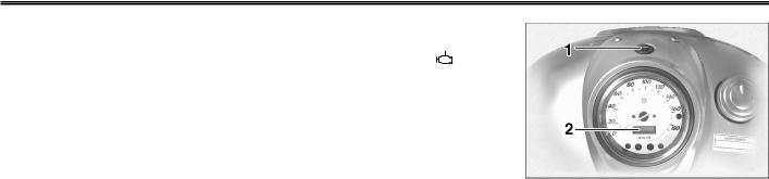
ФУНКЦИИ ПРИБОРОВ И ОРГАНОВ УПРАВЛЕНИЯ
|
EAU00057 |
EAU03192 |
||||
|
Сигнальная лампа указателя |
Предупредительная лампа неис- |
||||
|
поворотов “46 “ |
правности двигателя “ |
“ |
|||
|
При переводе переключателя |
Эта предупредительная лампа |
||||
|
указателя поворотов вправо или |
горит или мигает, когда элек- |
||||
|
влево эта сигнальная лампа на- |
трическая схема, контролирую- |
||||
|
чинает мигать. |
щая работу двигателя, неис- |
||||
|
правна. Если это происходит, по- |
|||||
|
3 |
ручите дилеру фирмы “Ямаха” |
||||
|
проверить систему самодиагно- |
|||||
|
стики. |
|||||
|
Электрические цепи этой лам- |
|||||
|
пы можно проверить следующим |
|||||
|
образом: |
|||||
|
1. |
Установите выключатель ос- |
||||
|
тановки двигателя в положе- |
|||||
|
íèå “#“. |
|||||
|
2. |
Поверните ключ в положение |
||||
|
“ON” (“ВКЛЮЧЕНО”). Если |
|||||
|
предупредительная лампа не |
|||||
|
загорается, обращайтесь к |
|||||
|
дилеру фирмы “Ямаха” по по- |
|||||
|
воду проверки электриче- |
|||||
|
ских цепей. |
EAU00063
Сигнальная лампа дальнего света “&“
Эта лампа горит, когда в фаре включена лампа дальнего света.
1.Кнопка “TRIP”
2.Одометр/Счетчик дальности поездки
EAU03193
Спидометр В узел спидометра входят циф-
ровой одометр и счетчик дальности поездки. Спидометр показывает скорость движения. Одо-
метр показывает общий пробег мотоцикла. Счетчик дальности поездки показывает пройденное расстояние с момента его последнего сброса на нуль. При нажатии на кнопку “TRIP” происходит переключение между режимом одометра “ODO” и режимом счетчика дальности поездки “TRIP”. Для сброса на нуль счет- чика дальности поездки, вызови-
те этот режим, нажав кнопку
3-3
![]()
ФУНКЦИИ ПРИБОРОВ И ОРГАНОВ УПРАВЛЕНИЯ
“TRIP”, после чего нажмите на кнопку “TRIP” еще раз и удерживайте ее нажатой по крайней мере одну секунду. Счетчик дальности данной поездки можно использовать для оценки расстояния, которое можно проехать с полным баком топлива. Эта информация позволяет планировать будущие остановки для заправки.
ПРИМЕЧАНИЕ :
Этот мотоцикл не оборудован тахометром, но он имеет встроенный ограничитель скорости, который предотвращает повышение частоты вращения двигателя выше 6 800 об/мин и повышение скорости движения мотоцикла выше 175 км/час.
EAU00109
Противоугонная сигнализация (дополнительная)
Этот мотоцикл можно оборудовать дополнительной противоугонной сигнализацией у дилера фирмы “Ямаха”. Дополнительную информацию можно получить у дилера фирмы “Ямаха”.
3-4
3
1.Выключатель сигнализации обгона “&“
2.Переключатель света фары “&/%“
3.Выключатель звукового сигнала “*“
4.Переключатель указателя поворотов
“4/6“
EAU00118
Выключатели на рукоятках
EAU00119
Выключатель сигнализации обгона “&“
Нажмите на этот выключатель для кратковременного включе- ния света фары.
EAU03888
Переключатель света фары “&/
%“
Установите этот переключатель в положение“&“ для включения дальнего света и в положение “% “ для включения ближнего света.

ФУНКЦИИ ПРИБОРОВ И ОРГАНОВ УПРАВЛЕНИЯ
EAU00129
Выключатель звукового сигнала “*“
Нажмите на этот выключатель для подачи звукового сигнала.
EAU03889
Переключатель указателя поворотов “4/ 6“
3Для индикации правого поворота переведите переключатель в положение “6“. Для индикации левого поворота переведите переключатель в положение “4“. При отпускании переключатель возвращается в центральное положение. Для отмены подачи сигнала поворота нажмите на переключатель после того, как он вернется в центральное положение.
1.Выключатель остановки двигателя “#/$“
2.Переключатель световых приборов “:/  /8“
/8“
3.Выключатель стартера “,“
EAU03890
Выключатель остановки двигателя “#/$“
Перед запуском двигателя установите этот выключатель в положение “#“. Устанавливайте этот выключатель в положение “$“ в аварийных ситуациях, например, при опрокидывании мотоцикла или при заедании троса дроссельной заслонки.
EAU03898
Переключатель световых приборов “:/ /8“
/8“
Устанавливайте этот переклю- чатель в положение “ “ äëÿ
“ äëÿ
включения дополнительного фо-
наря, освещения приборов и заднего габаритного фонаря. Устанавливайте переключатель в положение “:“ для того, чтобы включить также и свет фары. Устанавливайте переключатель в положение “8“ для того, чтобы выключить все осветительные приборы.
EAU00143
Выключатель стартера “,“
Нажмите на этот выключатель для проворачивания коленчатого вала двигателя стартером.
EC000005
Прочитайте инструкции по запуску на стр. 5-1 прежде, чем запускать двигатель.
3-5

ФУНКЦИИ ПРИБОРОВ И ОРГАНОВ УПРАВЛЕНИЯ
1. Рычаг сцепления
EAU00152
Рычаг сцепления
Рычаг сцепления расположен на левой рукоятке руля. Для выключения сцепления прижмите рычаг к рукоятке руля. Для включения сцепления отпусти-
те рычаг. Для обеспечения плавной работы сцепления рычаг следует нажимать быстро, а отпускать медленно.
Рычаг сцепления оборудован выключателем, который является частью системы блокировки цепей зажигания. (Описание системы блокировки цепей зажигания приведено на стр. 3-19.)
1. Педаль переключателя передач
EAU00157
Педаль переключателя передач (модель XVS1100)
Педаль переключателя передач расположена с левой стороны двигателя и используется в со- четании с рычагом сцепления
для переключения 5-ступенча- той коробки передач с шестернями постоянного зацепления, используемой на этом мотоцикле.
1. Педаль переключателя передач
EAU01215
Педаль переключателя передач (модель XVS1100A)
Педаль переключателя передач расположена с левой стороны двигателя и используется в со- четании с рычагом сцепления
для переключения 5-ступенча- той коробки передач с шестернями постоянного зацепления, используемой на этом мотоцикле.
ПРИМЕЧАНИЕ:
Используйте носок ноги или пятку для повышения передачи и носок ноги для понижения передачи.
3-6

ФУНКЦИИ ПРИБОРОВ И ОРГАНОВ УПРАВЛЕНИЯ
3
1. Рычаг тормоза
EAU00158
Рычаг тормоза
Рычаг тормоза расположен на правой рукоятке руля. Для вклю- чения переднего тормоза прижмите рычаг к рукоятке руля.
|
1. Педаль тормоза |
1. Педаль тормоза |
EAU00162
Педаль тормоза
Педаль тормоза расположена на правой стороне мотоцикла. Для того, чтобы включить задний тормоз нажмите на педаль тормоза.
3-7
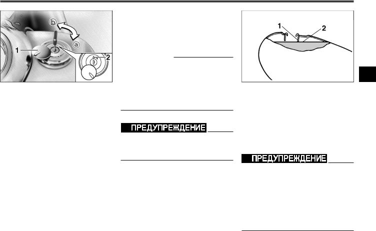
ФУНКЦИИ ПРИБОРОВ И ОРГАНОВ УПРАВЛЕНИЯ
1.Крышка замка крышки топливного бака
2.Значок “U“
а. Отпирание b. Запирание.
EAU02917
Крышка топливного бака
Как открыть крышку топливного бака Сдвиньте крышку замка в сторо-
ну, вставьте ключ в замок и поверните его по часовой стрелке на 1/4 оборота. Замок отпирается и крышку топливного бака можно открыть.
Как установить крышку топливного бака на место
1. Вставив ключ в замок, установите крышку на горловину топливного бака так, чтобы зна- чок “U“ был направлен вперед.
2.Поверните ключ против часовой стрелки в его исходное положение, выньте его, после чего сдвиньте крышку замка на место.
ПРИМЕЧАНИЕ :
Крышку топливного бака нельзя установить на место, не вставив ключ в ее замок. Кроме того, ключ нельзя вынуть, если крышка не установлена правильно и не заперта.
EW000024
Перед каждой поездкой прове-
ряйте, правильно ли установлена крышка топливного бака.
3
1.Наливная горловина топливного бака
2.Уровень топлива
EAU03753
Топливо
Проверьте, достаточное ли количество топлива в баке. Заполняйте топливный бак до нижней кромки наливной горловины, как показано на рисунке.
EW000130
8Не допускайте переполнения топливного бака, иначе топливо может начать выливаться при расширении в результате нагрева.
8Не допускайте попадания топлива на горячий двигатель.
3-8

ФУНКЦИИ ПРИБОРОВ И ОРГАНОВ УПРАВЛЕНИЯ
EAU00185
Немедленно вытирайте пролитое топливо чистой сухой мягкой тканью, поскольку топливо может повредить окрашенные поверхности или пластмассовые
детали.
3
EAU04202
Рекомендуемое топливо ТОЛЬКО ОБЫЧНЫЙ НЕЭТИЛИРОВАННЫЙ БЕНЗИН Емкость топливного бака : Общее количество :
17, литров Резервное количество :
4,5 литра
ECA00102
Используйте только неэтилированный бензин. Использование этилированного бензина вызывает серьезные повреждения таких внутренних деталей двигателя, как клапаны, поршневые кольца,
систему выхлопа и т. д.
Конструкция двигателя Вашей Ямахи рассчитана на использование обычного неэтилированного бензина с исследовательским октановым числом 91 или выше. При возникновении детонации (стуках в двигателе) используйте бензин другой марки или неэтилированное топливо более высокого качества. Использование неэтилированного топлива продлевает срок службы свечей зажигания и уменьшает расходы на техническое обслуживание.
OFF : Закрыт
1.Значок стрелки показывает на положение “OFF” (“ЗАКРЫТ”).
EAU02969
Топливный краник
Топливный краник служит для подачи топлива в карбюраторы, а также для фильтрации топлива.
Положения рычажка топливного краника показано на рисунках, а их описания приведены ниже.
OFF (ЗАКРЫТ)
Когда рычажок краника установлен в это положение, подача топлива перекрыта. Всегда устанавливайте рычажок краника в это положение, когда двигатель не работает.
3-9

ФУНКЦИИ ПРИБОРОВ И ОРГАНОВ УПРАВЛЕНИЯ
|
ON: Нормальное положение |
RES: Резервное положение |
3
1.Значок стрелки показывает на положение “ON” (“ОТКРЫТ”).
ON (ОТКРЫТ)
Когда рычажок краника установлен в это положение, топливо подается в карбюраторы. При запуске двигателя и при езде ус-
танавливайте рычажок топливного краника в это положение.
1.Значок стрелки показывает на положение “RES” (“РЕЗЕРВ”).
RES (РЕЗЕРВ)
Это обозначает “Резерв”. При установке рычажка топливного краника в это положение можно использовать резервный запас
топлива. Если во время движения у Вас кончился бензин, переведите рычажок краника в это положение. Если это произошло, залейте топливо при первой возможности и не забудьте перевести рычажок краника в положение “ON” (“ОТКРЫТ”) !
1.Рычажок пускового устройства (воздушной заслонки) “

 “
“
EAU02973
Рычажок пускового устройства (воздушной заслонки) “

 “
“
Для запуска холодного двигателя требуется более богатая воз- душно-топливная смесь, что
обеспечивается пусковым устройством (воздушной заслонкой).
Переведите рычажок в положение aдля использования пускового устройства (воздушной заслонки).
Переведите рычажок в положение b для возврата пускового устройства (воздушной заслонки) в исходное положение.
3-10

ФУНКЦИИ ПРИБОРОВ И ОРГАНОВ УПРАВЛЕНИЯ
ECA00038
Не используйте пусковое устройство (воздушную заслонку) дольше 3 минут, поскольку чрезмерное выделение тепла ведет к изменению цвета выхлопной трубы. Кроме того, длительное
3использование пускового устройства вызывает догорание топлива в выпускном тракте.
Если это происходит, выключи- те пусковое устройство (откройте воздушную заслонку).
XVS1100
1. Гайка
EAU01710
Сиденья (модель XVS1100)
Пассажирское сиденье
Как снять пассажирское сиденье Отверните гайку и поднимите пассажирское сиденье.
XVS1100
1.Выступ
2.Держатель сиденья
Как установить пассажирское сиденье Вставьте выступ в передней час-
ти пассажирского сиденья в держатель сиденья, как показано на
рисунке, а затем наверните гайку.
3-11
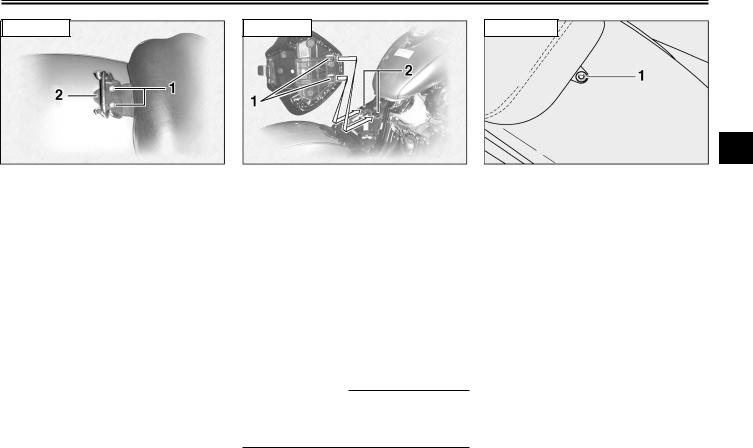
ФУНКЦИИ ПРИБОРОВ И ОРГАНОВ УПРАВЛЕНИЯ
3
1.Áîëò (2 øò.)
2.Скоба
Водительское сиденье
Как снять водительское сиденье
1.Снимите пассажирское сиденье.
2.Выверните болты и снимите скобу, а затем поднимите водительское сиденье.
1.Выступ (2 шт.)
2.Держатель сиденья (2 шт.)
Как установить водительское сиденье
1.Вставьте выступы в передней части водительского сиденья в держатели сиденья, как
показано на рисунке, и установите сиденье на место.
2.Установите снятую скобу и заверните болты.
3.Установите пассажирское сиденье.
ПРИМЕЧАНИЕ :
Перед началом движения проверьте, надежно ли закреплены сиденья.
1. Áîëò
EAU03202
Сиденья (модель XVS1100А)
Пассажирское сиденье
Как снять пассажирское сиденье Выверните болт, а затем поднимите пассажирское сиденье.
3-12

ФУНКЦИИ ПРИБОРОВ И ОРГАНОВ УПРАВЛЕНИЯ
XVS1100A
3
1.Выступ
2.Держатель сиденья
Как установить пассажирское сиденье Вставьте выступ в передней час-
ти водительского сиденья в держатель, как показано на ри-
сунке, установите сиденье на место, а затем заверните болт.
XVS1100A
1. Áîëò
Водительское сиденье
Как снять водительское сиденье
1.Снимите пассажирское сиденье.
2.Выверните болт, а затем под-
нимите водительское сиденье.
XVS1100A
1.Выступ (2 шт.)
2.Держатель сиденья (2 шт.)
Как установить водительское сиденье
1.Вставьте выступы в передней части водительского сиденья в держатели, как показа-
но на рисунке, установите сиденье на место, а затем заверните болт.
2.Установите пассажирское сиденье.
ПРИМЕЧАНИЕ :
Перед началом движения проверьте, надежно ли закреплены сиденья.
3-13
![]()
ФУНКЦИИ ПРИБОРОВ И ОРГАНОВ УПРАВЛЕНИЯ
1.Держатель для шлема
2.Отпирание
EAU00260
Держатель для шлема
Для того, чтобы открыть держатель для шлема, вставьте ключ
âзамок и поверните его, как показано на рисунке.
Для того, чтобы запереть держатель для шлема, установите его
âисходное положение и выньте ключ.
EW000030
Никогда не ездите на мотоцикле со шлемом, закрепленном на держателе, поскольку шлем может зацепиться за какое-нибудь препятствие, что ведет к потере
управления, а возможно и к не- счастному случаю.
3
|
1. Крышка багажного отделения |
1. Замок багажного отделения |
|
EAU01869 |
|
|
Багажное отделение |
Как открыть багажное отделе- |
|
Багажное отделение расположе- |
íèå |
|
но на левой стороне мотоцикла. |
1. Сдвиньте крышку замка в |
|
сторону, вставьте ключ и по- |
|
|
верните его по часовой |
|
|
стрелке. |
3-14

ФУНКЦИИ ПРИБОРОВ И ОРГАНОВ УПРАВЛЕНИЯ
3
|
1. Крышка багажного отделения |
1. Крышка багажного отделения |
|
|
2. Откиньте крышку багажного |
Как закрыть багажное отделе- |
|
|
отделения, как показано на |
íèå |
|
|
рисунке. |
1. |
Установите крышку багажно- |
|
го отделения в исходное по- |
||
|
ложение, как показано на ри- |
||
|
сунке. |
||
|
2. |
Поверните ключ против часо- |
|
|
вой стрелки, выньте его, по- |
||
|
сле чего закройте крышку |
||
|
замка. |
EAU03194
Регулировка амортизатора
Узел амортизатора расположен под водительским сиденьем и оборудован кольцом регулировки предварительного натяга пружины.
EC000015
Ни в коем случае не поворачи- вайте регулировочный механизм за пределы максимальной или минимальной установки.
Регулируйте предварительный натяг пружины следующим образом :
1.Снимите водительское сиденье. (Описания снятия и установки водительского сиденья приведены на стр. 3-11 [модель XVS1100] или на стр. 3-12 [модель XVS1100A].)
3-15

ФУНКЦИИ ПРИБОРОВ И ОРГАНОВ УПРАВЛЕНИЯ
XVS1100
3
|
1. Пистон быстрого крепления (3 шт.) |
1. Панель блока зажигания |
1. Пистон быстрого крепления (3 шт.) |
|
|
2. Извлеките пистоны быстрого |
3. Отведите панель блока зажи- |
2. Грязевой щиток |
|
|
4. Снимите грязевой щиток, вы- |
|||
|
крепления панели блока за- |
гания вправо. |
||
|
нув пистоны быстрого креп- |
|||
|
жигания, нажимая на их цен- |
|||
|
ления. |
|||
|
тральную часть отверткой и |
|||
|
вынимая их. |
3-16
 Loading…