- Manuals
- Brands
- Volvo Manuals
- Automobile
- V90 cross country
- Owner’s manual
-
Contents
-
Table of Contents
-
Troubleshooting
-
Bookmarks
Quick Links
O W N E R ‘ S M A N U A L
Related Manuals for Volvo V90 CROSS COUNTRY
Summary of Contents for Volvo V90 CROSS COUNTRY
-
Page 1
O W N E R ‘ S M A N U A L… -
Page 3
VÄLKOMMEN! We trust that you will enjoy many years of safe driving in your Volvo, an cle if you may be affected by alcohol, medication or any impairment that automobile designed with your safety and comfort in mind. To help get could hinder your ability to drive. -
Page 4: Table Of Contents
Options, accessories and the On- Seat belt pretensioners board Diagnostic (OBDII) socket Buckling and unbuckling seat belts Volvo ID Door and seat belt reminders Volvo and the environment Airbag system IntelliSafe—driver support Driver/passenger side airbags Sensus Occupant weight sensor Owner’s manual and the environment…
-
Page 5
INSTRUMENTS AND CONTROLS Top tether anchors Instruments and controls Seats Integrated booster cushion* Instrument panel Manually operated front seats Instrument panel settings Power front seats* Raising the integrated booster cushion* Indicator symbols in the instrument panel Adjusting power front seats* Stowing the integrated booster cushion* Warning symbols in the instrument panel Using the power seat memory function*… -
Page 6
CLIMATE Using turn signals Categories in Settings view Climate control system Passenger compartment lighting Changing system settings in Set- Climate system sensors tings view Home safe lighting Perceived temperature Resetting the settings view Approach lighting Air quality Driver profiles Using the windshield wipers Passenger compartment air filter Selecting a driver profile Activating/deactivating the rain sensor… -
Page 7
LOADING AND STORAGE LOCKS AND ALARM Passenger compartment storage spaces Locks and remote keys Turning steering wheel heating* on and off Tunnel console Remote key Electrical sockets Remote key’s range Using the glove compartment Red Key* Sun visors Antenna locations for the start and lock system Loading Locking/unlocking from outside the… -
Page 8
DRIVER SUPPORT Start and lock system type designations Driver support systems Distance Alert* Adjustable steering force* Using Distance Alert* Roll stability control (RSC) Distance Alert* limitations Electronic Stability Control (ESC) Adaptive Cruise Control (ACC)* Electronic Stability Control (ESC) Starting and activating Adaptive sport mode Cruise Control (ACC)* Electronic Stability Control (ESC) -
Page 9
Changing target vehicles and auto- Blind Spot Information (BLIS)* with Park Assist Camera (PAC)* trajectory matic braking with Pilot Assist Cross Traffic Alert (CTA)* symbols lines and fields and messages Pilot Assist limitations Starting the Park Assist Camera (PAC)* Road Sign Information (RSI)* Pilot Assist symbols and messages Park Assist Camera (PAC)* limitations Road Sign Information (RSI)* operation… -
Page 10
STARTING AND DRIVING INFOTAINMENT Starting and driving Parking brake malfunctions The infotainment system Ignition modes Hill Start Assist Apps (applications) Starting the engine Auto-hold brake function Sound settings Turning the engine off Radio Low Speed Control (LSC)* Jump starting Hill Descent Control (HDC) Changing and searching for radio stations Automatic transmission… -
Page 11
WHEELS AND TIRES Tethering (Wi-Fi sharing) Tires CD (media) player* Streaming media through a Blue- Internet connection troubleshooting Tire direction of rotation tooth connection Deleting Wi-Fi networks Tread wear indicator ® Connecting a Bluetooth device Wi-Fi technology and security Checking tire inflation pressure Playing media through the USB socket Vehicle modem settings Tire Pressure Monitoring System (TPMS) -
Page 12
MAINTENANCE AND SERVICING Loading specifications Volvo’s service program Battery symbols Uniform Tire Quality Grading Vehicle status Support battery Booking service and repairs Fuses Remote updates Replacing fuses System updates Fuses in the engine compartment Hoisting the vehicle Fuses in the passenger compartment… -
Page 13
SPECIFICATIONS INDEX Label information Index Dimensions Weights Engine specifications Engine oil specifications and volume Coolant specifications Transmission fluid specification and volume Brake fluid specification and volume Fuel tank volume Air conditioning refrigerant Tire inflation pressure table… -
Page 15
INTRODUCTION… -
Page 16
Volvo’s sup- and interior images of the vehi- specifications as well as a sum- port website. -
Page 17: Introduction
It is also important that the vehicle be oper- ated, maintained and serviced according to Volvo’s recommendations/instructions in the owner’s manual. All articles sorted by cate- Changing the language used in the gory.
-
Page 18: Navigating In The Digital Owner’s Manual
INTRODUCTION Navigating in the digital owner’s Symbols and their descriptions Symbols and their descriptions manual Exterior/interior views of Leads to short instructional The digital on-board owner’s manual is the vehicle in which certain videos for various vehicle accessed from the center display. The contents areas/components are functions.
-
Page 19
INTRODUCTION Searching using categories Saving/deleting favorites 1. Tap Exterior Interior followed by The articles in the owner’s Save an article as a favorite by tapping the star > Exterior/interior views will be displayed manual are structured in main ) at the upper right when an article is open. with hotspots, which lead to relevant arti- and sub-categories. -
Page 20: Owner’s Manual In Mobile Devices
Using the center display keyboard (p. 47) This QR code will take you directly to the app or you can search for «Volvo manual» in the App Store or Google Play. The mobile app is available at the App Store and Google…
-
Page 21: Additional Information About Your Vehicle
Mobile apps Beginning with model year 2014, the owner’s manual is available in the form of an app for cer- tain Volvo models. The Volvo On Call app can also be found here. Owner’s manuals for earlier model Volvos Owner’s manuals for earlier model Volvos are available in PDF format.
-
Page 22: Using The Owner’s Manual
There are several displays in the vehicle that mation and how to contact Volvo if help is show messages generated by various systems required. and functions in the vehicle. The appearance of…
-
Page 23
INTRODUCTION Risk of damage to the vehicle White ISO symbols and white text/image on a Arrows containing letters are used to indi- black background. These decals provide general cate movement. information. If there are no illustrations associated with a step-by-step list, the steps in the procedure are NOTE indicated by ordinary numbers. -
Page 24: Crash Event Data
Whether or not the driver and passenger them to diagnose and rectify any faults that have safety belts were buckled/fastened; occurred in the vehicle and to enable Volvo to ful- • fill legal and other regulatory requirements. Infor- How far (if at all) the driver was depressing mation thus registered in the vehicle is registered the accelerator and/or brake pedal;…
-
Page 25: Options, Accessories And The On- Board Diagnostic (Obdii) Socket
In Canada sion requirements. In some cases it may formed only by a trained and qualified Volvo be difficult or impossible to comply with Volvo Car Canada Ltd. service technician.
-
Page 26
If your vehicle is involved in an accident, may and may not be safely installed in your unseen damage may affect its drivability and Volvo. In all cases, please consult a trained WARNING safety. and qualified Volvo service technician before Volvo Cars takes no responsibility for the con- installing any accessory in or on your vehicle. -
Page 27: Volvo Id
• matically to this address. Connecting to the Internet (p. 450) undesired operation. These services vary and may be subject to change. Consult your Volvo retailer.
-
Page 28: Volvo And The Environment
Volvo was the first in the world to introduce into Lane Keeping Aid* alerts the driver if the vehicle if the check engine (malfunction indicator)
-
Page 29
INTRODUCTION • High and low beam headlights (p. 141) • Cross Traffic Alert (CTA)* (p. 321) • Blind Spot Information (BLIS)* (p. 319) • City Safety™ (p. 307) • Driving lane assistance (p. 330) • Airbag system (p. 67) • Roll stability control (RSC) (p. -
Page 30: Sensus
Sensus Sensus provides an intelligent interface and Internet-connected service with an intuitive navi- Sensus is the core of your personal Volvo experi- gation structure that offers access to relevant ence and provides information, entertainment information when it is needed, with minimal dis- and features that make owning your vehicle eas- tractions.
-
Page 31
INTRODUCTION Information when it’s needed, where it’s needed Information is presented in different displays depending on how it should be prioritized (generic illustration) Head-up-display* ately, such as traffic warnings, speed information Instrument panel and navigation. Road sign information and incom- ing phone calls are also displayed here. -
Page 32
INTRODUCTION • Many of the vehicle’s main functions are con- Head-up display (HUD)* (p. 117) trolled from the center display, a touchscreen that • Instrument panel (p. 97) reacts to taps or other gestures. The number of • Voice control (p. 120) physical buttons is thereby minimized. -
Page 33: Owner’s Manual And The Environment
INTRODUCTION Owner’s manual and the Glass environment Laminated glass The wood pulp in Volvo’s printed owner’s infor- The windshield and panoramic roof* are made of ® mation comes from FSC (Forest Stewardship laminated glass, which is reinforced to help pre- ®…
-
Page 34: Center Display Overview
INTRODUCTION Center display overview Many of the vehicle’s functions are controlled from the center display. Three of the center display’s basic views. Swipe to the right/left to access the Function/App view (generic illustration)
-
Page 35
INTRODUCTION Function view: vehicle functions can be acti- The extra sub-view: the most recently used vated/deactivated by tapping. Certain func- apps/vehicle functions that do not belong in tions are called «trigger functions», which any of the other sub-views are listed here. Camera open settings windows, e.g., Tap the sub-view to expand it. -
Page 36: Using The Center Display
INTRODUCTION Using the center display The screen reacts differently depending on CAUTION whether the user taps, drags or swipes on the Many of the vehicle’s functions can be con- Do not touch the screen with sharp objects screen. This makes it possible to move between trolled and settings can be made from the because this could cause scratches.
-
Page 37
INTRODUCTION Procedure Gesture Result Drag Moves between screen views, scrolls in a list, text or a view. Press and hold to drag apps or objects in a list. Swipe Moves between screen views, scrolls in a list, text or a view Stretch Zooms in. -
Page 38
INTRODUCTION Turning off and reactivating the center Moving apps and vehicle function 2. Reactivate by pressing the Home button display briefly. buttons Apps and function buttons can be moved and > The view that was displayed when the organized in their respective views. screen was turned off will be displayed again. -
Page 39
INTRODUCTION Digital controls are available for many of the vehi- cle’s functions. For example, to set the tempera- ture: • Drag the control to the desired temperature • − to raise or lower the temperature incrementally, or • Tap the desired temperature on the control Related information •… -
Page 40: Navigating In The Center Display’s Views
INTRODUCTION Navigating in the center display’s used app/vehicle function is a music app, the NOTE views Media sub-view will be displayed. When the vehicle is moving: There are 5 different basic views in the center The sub-views display brief information about the •…
-
Page 41
INTRODUCTION Expanding a sub-view from the standard view Standard view and an expanded sub-view in the center display… -
Page 42
INTRODUCTION Status bar Expanding a sub-view: In expanded mode, open the app in full-screen mode by tap- Current vehicle activities are shown in the status – To expand sub-view one, two or three: tap ping the symbol. bar at the top of the screen. Network and con- the screen anywhere in the sub-view. -
Page 43
INTRODUCTION App view To leave (minimize) Top view, tap the screen out- When applicable, swipe downward to scroll in the side of this view or tap at the bottom of Top view list of apps (depending on the number of apps and swipe upward. -
Page 44
INTRODUCTION Swipe the screen from left to right to access Function view from Home view. From Function view, you can activate/deactivate various vehicle Drive Modes Speed Sign functions such as Assist Park Assist When applicable, swipe upward to scroll in the list of functions (depending on the number of func- tions). -
Page 45: Symbols In The Center Display Status Bar
INTRODUCTION Symbols in the center display status Changing center display settings Symbol Meaning The center display activates automatically when Audio source being played. The following table provides an overview of the the driver’s door is opened. Settings can be symbols used in the center display’s status bar. made for e.g., sounds, background and themes.
-
Page 46
INTRODUCTION ground will be light and the text will be dark, which can increase readability in strong ambient lighting. These alternatives are always available and do not shift automatically according to changes in ambient lighting. Related information • Using the center display (p. 34) •… -
Page 47: Function View Buttons
INTRODUCTION Function view buttons Different types of buttons on-screen function buttons. From the Home view, swipe from left to right on the screen to There are three different types of vehicle function The Function view, which is one of the center come to the Function view.
-
Page 48
INTRODUCTION The yellow triangle indicates that the function is not working correctly Related information • Center display overview (p. 32) • Navigating in the center display’s views (p. 38) • Categories in Settings view (p. 171) -
Page 49: Using The Center Display Keyboard
INTRODUCTION Using the center display keyboard A keyboard can be used on the center display to enter characters and search for e.g., destina- tions using the navigation system, adding con- tacts in phone book, etc. It is also possible to use handwriting on the screen.
-
Page 50
INTRODUCTION Keyboard function buttons (the appearance may vary depending on language settings, context, etc.) Field for possible search hits. The word word to select it. The keyboard may not sup- The characters that can be entered are lan- changes as new letters are added. Scroll in port all language selections, in which case guage-dependent (see point 7). -
Page 51
INTRODUCTION Several buttons (depending on the context languages and tap a language to use it. To When more than one language for which the keyboard is being used) will be add keyboard languages, see the heading has been selected, this button displayed here. -
Page 52
INTRODUCTION Special characters Entering characters 1. Enter a handwritten character (1) using a fin- gertip or by holding e.g., a pen near the screen. > Several character suggestions will appear (3). The most likely character will be at the top of the list. CAUTION Do not touch the screen with sharp objects because this could cause scratches. -
Page 53
INTRODUCTION Erasing/changing handwritten characters New lines Erase a character by swiping over the handwriting area Create a new line by drawing above the characters as shown in the illustration Blank spaces Characters can be erased/changed in several ways: • Tap the desired character in the list (3). •… -
Page 54: Changing Settings In Different Types Of Apps
5. Press the Home button, tap the screen out- air bag deployment. side of Top view or pull Top view up. Due to the above, Volvo Car USA does not sup- port the use of aftermarket, alternative or any- Third-party apps…
-
Page 55: Driver Distraction
Never program your audio system while or if you allow accessories to be installed by in the driving environment. Your new Volvo is, or the vehicle is moving. Program radio pre- someone unfamiliar with your vehicle.
-
Page 56
Use the following contact information if you The driver is always responsible for operating ports certification by the National Institute for would like to get in touch with Volvo in the Uni- the vehicle in a safe manner and for comply- Automotive Service Excellence (A.S.E.). -
Page 57
INTRODUCTION Volvo Roadside Assistance Your new Volvo comes with a four year Volvo Roadside Assistance program. Additional information, features, and benefits of this program are described in a separate informa- tion package in your glove compartment. If you require assistance, dial: In the U.S. -
Page 59
SAFETY… -
Page 60: General Safety Information
It must never be allowed to ride upward. while you are driving, have the vehicle Remove all slack from the belt and ensure that it inspected by a trained and qualified Volvo fits close to the body without any twists. service technician as soon as possible.
-
Page 61: Whiplash Protection System
In the event of certain rear-end collisions, the must be inspected by a trained and quali- hinges and brackets of the front seat backrests fied Volvo service technician, even if the are designed to change position slightly to allow seats appear to be undamaged. Certain…
-
Page 62: Occupant Safety
Our concern for safety dates back to 1927 when • Take a driver-retraining course. the first Volvo rolled off the production line. • Have your eyes checked regularly. Three-point seat belts (a Volvo invention), safety cages, and energy-absorbing impact zones were •…
-
Page 63: Reporting Safety Defects
Car USA, LLC. If NHTSA receives simi- soon as possible. Please check with lar complaints, it may open an investi- your local retailer or Volvo Car USA, gation, and if it finds that a safety LLC if your vehicle is covered under defect exists in a group of vehicles, it these conditions.
-
Page 64: Recall Information
For any questions regarding open recalls for your passenger’s seat. We also recommend vehicle, please contact your authorized Volvo Seat belt maintenance that children who have outgrown these retailer. If your retailer is unable to answer your…
-
Page 65: Seat Belt Pretensioners
Volvo service technician only. as the airbags. sion. Some or all of the pretensioners will be •…
-
Page 66: Buckling And Unbuckling Seat Belts
SAFETY Buckling and unbuckling seat belts 2. Insert the latch plate into the receptacle. The 3. The height of the seat belts in the front seats seat belt retractor is normally «unlocked» and can be adjusted. The height of the shoulder Seat belts should be used by all occupants in you can move freely, provided that the shoul- section of the seat belt must be correctly…
-
Page 67
SAFETY Unbuckling the seat belt 4. Tighten the lap section of the seat belt by pulling the diagonal section upward toward To remove the seat belt, press the red section on the shoulder. the seat belt receptacle. Before exiting the vehi- cle, check that the seat belt retracts fully after being unbuckled. -
Page 68: Door And Seat Belt Reminders
SAFETY Door and seat belt reminders Seat belt reminder Rear seats The rear seat belt reminder has two functions. The door and seat belt reminders are intended to alert all occupants of the vehicle that their • It indicates which seat belts are buckled in seat belts should be buckled before the vehicle the rear seats.
-
Page 69: Airbag System
Volvo service technician for while you are driving, have the vehicle repairs. inspected by a trained and qualified Volvo Before attempting to tow the vehicle: service technician as soon as possible. 1. Switch off the ignition for at least •…
-
Page 70
SAFETY The location of the front airbags is indicated by certain non-frontal collisions where rapid WARNING SRS AIRBAG embossed on the steering wheel deceleration occurs. • The airbags in the vehicle are designed to pad and above the glove compartment, and by •… -
Page 71
SRS system, please contact a trained and at partial capacity. If the impact is more qualified Volvo service technician or Volvo cus- severe, the airbags are triggered at full tomer support: capacity. -
Page 72: Occupant Weight Sensor
Never try to open the airbag cover on the Passenger’s side airbag decal steering wheel or the passenger’s side dashboard. This should only be done by a WARNING trained and qualified Volvo service techni- cian. • Children must never be allowed in the •…
-
Page 73
• out by an a trained and qualified Volvo the front passenger’s seat is unoccupied, or service technician. has small/medium objects in the front seat, However, if a fault is detected in the system: •… -
Page 74
This condition reflects limitations of the OWS Volvo recommends that children always be properly restrained in appropriate child restraints in the rear seats. Do not assume classification capability. It does not indicate OWS that the passenger’s side front airbag is disabled unless the malfunction. -
Page 75
SAFETY WARNING WARNING WARNING • • • No objects that add to the total weight on Keep the following points in mind with Do not place any type of object on the the seat should be placed on the front respect to the OWS system. -
Page 76: Side Impact Airbags
SIPS airbag system. This should be done only by a trained and The SIPS airbag system is designed to help qualified Volvo service technician. increase occupant protection in the event of cer- • In order for the SIPS airbag to provide its tain side impact collisions.
-
Page 77: Inflatable Curtains
IC system. This should be and the occupant of the outboard rear seating reduced. done only by a trained and qualified Volvo positions in certain side impact collisions. service technician. If the vehicle has been involved in a collision, the •…
-
Page 78: Starting Or Moving A Vehicle In Safety Mode
It must be trans- • General safety information (p. 58) ported on a flatbed tow truck to a trained and qualified Volvo service technician for inspec- 2. Turn the start knob clockwise as far as possi- tion/repairs. ble and release it.
-
Page 79: Child Safety
A specially designed and tested booster cushion erly restrained. A child restraint system can help and backrest can be obtained from your Volvo LATCH attachments, which make it more conven- ient to install child seats.
-
Page 80
Volvo’s recommendations • Volvo strongly recommends that everyone in Why does Volvo believe that no child should sit in the vehicle be properly restrained. the front seat of a car? It’s quite simple really. A •… -
Page 81: Child Restraints
SAFETY Child restraints Suitable child restraints should always be used when children travel in the vehicle. Child restraint systems Convertible seat Booster cushion WARNING WARNING A child seat should never be used in the front Always refer to the child restraint manufactur- passenger seat of any vehicle with a front er’s instructions for detailed information on Infant seat…
-
Page 82: Infant Seats
A small child’s head represents a consid- erable part of its total weight and its neck WARNING is still very weak. Volvo recommends that Do not use child safety seats or child booster children up to age 4 travel, properly cushions/backrests in the front passenger’s restrained, facing rearward.
-
Page 83
SAFETY WARNING A child seat should never be used in the front passenger seat of any vehicle with a front passenger airbag – not even if the «Passen- ger airbag off» symbol near the rear-view mir- ror is illuminated (on vehicles equipped with Occupant Weight Sensor). -
Page 84: Convertible Seats
SAFETY Convertible seats NOTE WARNING Suitable child restraints should always be used The locking retractor will automatically It should not be possible to move the child when children (depending on their age/size) are restraint (child seat) more than 1 in. (2.5 cm) release when the seat belt is unbuckled and seated in the vehicle.
-
Page 85
• A small child’s head represents a consider- able part of its total weight and its neck is still very weak. Volvo recommends that children up to age 4 travel, properly restrained, facing rearward. In addition, Volvo recommends that children should ride rearward facing, properly restrained, as long as possible. -
Page 86
SAFETY Related information NOTE WARNING • ISOFIX/LATCH lower anchors (p. 86) The locking retractor will automatically It should not be possible to move the child • Top tether anchors (p. 88) restraint (child seat) more than 1 in. (2.5 cm) release when the seat belt is unbuckled and in any direction along the seat belt path. -
Page 87: Booster Cushions
SAFETY Booster cushions Related information 3. Fasten the seat belt by inserting the latch • plate into the buckle (lock) until a distinct ISOFIX/LATCH lower anchors (p. 86) Securing a booster cushion click is audible. • Top tether anchors (p. 88) •…
-
Page 88: Isofix/Latch Lower Anchors
4. Firmly tension the lower child seat straps according to the manufacturer’s instructions. WARNING Volvo’s ISOFIX/LATCH anchors conform to Fasten the attachment correctly to the ISOFIX/LATCH FMVSS/CMVSS standards. Always refer to lower anchors the child restraint system’s manual for weight and size ratings.
-
Page 89: Lower Child Seat Attachment Points
SAFETY Related information Lower child seat attachment points WARNING • Top tether anchors (p. 88) The vehicle is equipped with lower attachment A child seat should never be used in the front points for child seats in the rear seats. passenger seat of any vehicle with a front passenger airbag –…
-
Page 90: Top Tether Anchors
Top tether anchors 3. Attach lower tether straps to the lower ISO- WARNING FIX/LATCH anchors. If the child restraint is Your Volvo is equipped with child restraint top • Always refer to the recommendations not equipped with lower tether straps, or the tether anchorages, located on the rear side of made by the child restraint manufacturer.
-
Page 91: Integrated Booster Cushion
SAFETY Integrated booster cushion* WARNING Volvo’s optional integrated booster cushions are DEATH or SERIOUS INJURY can located in the rear seat’s outer positions and are occur designed to raise the child higher so that the • Follow all instructions on this shoulder strap crosses over the child’s collar- bone, not over the neck.
-
Page 92: Raising The Integrated Booster Cushion
SAFETY • Raising the integrated booster Canadian models The integrated two-stage booster cushion is cushion* set in the correct position according to the Stage 1 Stage 2 child’s height and weight The integrated booster cushions in the rear • Weight 22 –…
-
Page 93
SAFETY Upper position (assuming the booster cushion is already in the lower position): Press the booster cushion rearward to lock it Lift the front edge of the booster cushion in position. and press it rearward toward the backrest to lock it in position. Press the button to release the booster cushion. -
Page 94: Stowing The Integrated Booster Cushion
The booster cushion should also be replaced if it is badly worn or damaged in any way. This work should be performed by a trained and qualified Volvo service technician only. * Option/accessory.
-
Page 95
The booster cushion should folded down. also be replaced if it is badly worn or damaged in any way. This work should be performed by a trained and qualified Volvo service technician only. * Option/accessory. -
Page 97
INSTRUMENTS AND CONTROLS… -
Page 98: Instruments And Controls
INSTRUMENTS AND CONTROLS Instruments and controls Display/function/control Display/function/control This overview shows the location of the primary Instrument panel Front reading lights and courtesy lighting displays, and controls/buttons/switches. Wipers/washers, rain sensor* Laminated panoramic roof* Right-side steering wheel keypad Ceiling console display Steering wheel adjustment Manual rearview mirror auto-dim (certain markets only)
-
Page 99: Instrument Panel
If the instrument panel turns off, does not activate when the ignition is switched on or is completely/partially not possible to read, do not drive the vehicle. Contact a Display/function/control trained and qualified Volvo service techni- cian. Memory control for: • power seats* •…
-
Page 100
INSTRUMENTS AND CONTROLS • 12″ Instrument panel* 8″ instrument panel Cell phone • Voice control • Compass* Right side • Tachometer (depending on current driving mode) • ECO gauge (depending on current driving mode) • Gear indicator • Current driving mode •… -
Page 101
INSTRUMENTS AND CONTROLS Position for variable symbols Related information Center • • Speedometer Instrument panel App menu (p. 111) • • Road sign information* Warning symbols in the instrument panel (p. 103) • Cruise control/speed limiter information • Indicator symbols in the instrument panel •… -
Page 102: Instrument Panel Settings
INSTRUMENTS AND CONTROLS Instrument panel settings 3. Select the information to be displayed in the 2. To select a language, tap System background: Instrument panel settings can be made from its System Languages and Units System Settings • app menu and under in the center dis- Language.
-
Page 103: Indicator Symbols In The Instrument Panel
If this happens, please the automatic high beams are off. have your vehicle checked by a High beam indicator trained and qualified Volvo service technician as soon as possible. The symbol will illuminate when the high beams are on or when…
-
Page 104
INSTRUMENTS AND CONTROLS Symbol Explanation Symbol Explanation Symbol Explanation Automatic/active high beams Lane keeping aid Not in use White symbol: lane keeping aid on The symbol will be blue when the and marker lines detected. automatic high beams are on. The Stability system Gray symbol: lane keeping aid on parking lights will also be on. -
Page 105: Warning Symbols In The Instrument Panel
Have the sys- driver that an important function is tem(s) inspected by a trained and activated or that a serious fault qualified Volvo service technician has occurred that may affect the as soon as possible. vehicle’s drivability. The warning…
-
Page 106: Ambient Temperature Sensor
DO NOT DRIVE. Have the vehicle towed engine oil level is too low. Stop the to a trained and qualified Volvo service engine immediately and check the technician and have the brake system engine oil level. Add oil if neces- inspected.
-
Page 107: Clock
INSTRUMENTS AND CONTROLS Clock Settings Automatic time Auto Time Changing measurement standard in the center The function is also available, which The clock is displayed in the instrument panel display: adjusts the time zone automatically, depending and in the center display. Auto Time on the vehicle’s location.
-
Page 108: Fuel Gauge
INSTRUMENTS AND CONTROLS Fuel gauge Instrument panel licenses The fuel gauge in the instrument panel shows BSD 4-clause «Original» or «Old» the current fuel level and indicates when the License level is low. Copyright ©) 1982, 1986, 1990, 1991, 1993 The Regents of the University of California.
-
Page 109
INSTRUMENTS AND CONTROLS BSD 2-clause “Simplified” license ANY EXPRESS OR IMPLIED WARRANTIES, the documentation and/or other materials Copyright ©) <YEAR>, <OWNER> All rights INCLUDING, BUT NOT LIMITED TO, THE provided with the distribution. IMPLIED WARRANTIES OF MERCHANTABILITY reserved. 3. Neither the name of the organisation nor the AND FITNESS FOR A PARTICULAR PURPOSE names of its contributors may be used to Redistribution and use in source and binary… -
Page 110
INSTRUMENTS AND CONTROLS OR TORT (INCLUDING NEGLIGENCE OR distribution) o You can use this software for must contact us to verify this. The FreeType OTHERWISE) ARISING IN ANY WAY OUT OF whatever you want, in parts or full form, project is copyright (C) 1996-1999 by David THE USE OF THIS SOFTWARE, EVEN IF without having to pay us. -
Page 111
INSTRUMENTS AND CONTROLS documentation. The copyright notices of the Discusses bugs, as well as engine internals, and with the following additions to the disclaimer: unaltered, original files must be preserved in design issues, specific licenses, porting, etc. There is no warranty against interference with all copies of source files. -
Page 112
INSTRUMENTS AND CONTROLS Greg Roelofs 1. The origin of this source code must not be Permission is hereby granted, free of charge, to misrepresented. any person obtaining a copy of this software and Tom Tanner associated documentation files (the «Software»), 2. -
Page 113: Instrument Panel App Menu
INSTRUMENTS AND CONTROLS Instrument panel App menu This software is provided ‘as-is’, without any limitation the rights to use, copy, modify, merge, express or implied warranty. In no event will the publish, distribute, sublicense, and/or sell copies The App (application) menu in the instrument authors be held liable for any damages arising of the Software, and to permit persons to whom panel provides quick access to commonly used…
-
Page 114: Using The Instrument Panel App Menu
INSTRUMENTS AND CONTROLS Using the instrument panel App Opening/closing the App menu Functions menu – Press the App menu (1). Trip com- Select a trip odometer, make The App (application) menu in the instrument The App menu cannot be opened if there are puter instrument panel display set- panel is controlled using the right-side steering…
-
Page 115: Messages In The Instrument Panel And Center Display
INSTRUMENTS AND CONTROLS Messages in the instrument panel Message Action and center display Stop safely Stop and switch off the Information and warning messages are dis- engine. There is a risk of played in the instrument panel and center dis- serious damage to the vehi- play.
-
Page 116: Ment Panel And Center Display
Instrument panel played with graphics, symbols or buttons for e.g., Part of the message is context-dependent. confirming a message or accepting a request. Contact a Volvo retailer or a trained and qualified Volvo service technician. Pop-up messages Center display Messages are sometimes displayed in pop-up windows.
-
Page 117: Ment Panel And Center Display
INSTRUMENTS AND CONTROLS For messages without buttons: Handling new messages For messages with buttons: – Close the message by pressing (2) or let the message time-out after a short period. – Tap the button to carry out the action or let the message time-out after a short period.
-
Page 118: Handling Messages Stored From The Instrument Panel And Center Display
INSTRUMENTS AND CONTROLS Handling messages stored from the Reading saved messages Booking service: instrument panel and center display Reading a saved message immediately: – With the message in expanded form, tap Messages in the instrument panel and center Request appoint. Call to make –…
-
Page 119: Head-Up Display (Hud)
INSTRUMENTS AND CONTROLS Head-up display (HUD)* Messages saved from the center Messages saved in Top view are erased automat- display ically when the engine is switched off. The head-up display provides information such as speed, cruise control functions, navigation, Related information traffic sign information, incoming phone calls, •…
-
Page 120
This graphic will illuminate • the use of polarizing sunglasses even if the HUD is turned off. • the use of an aftermarket or non-Volvo replacement windshield • not sitting in the center of the driver’s seat •… -
Page 121
Show Driver Support If the windshield has to be replaced, contact a Show Phone trained and qualified Volvo service technician or authorized workshop. The correct type of replace- This selection can be stored as a personal set- ment windshield must be used for a head-up dis- ting in a driver profile. -
Page 122: Voice Control
3. Use the buttons on the right-side steering player, a Bluetooth-connected cell phone, cli- (p. 38) wheel keypad to calibrate the horizontal posi- mate system and the Volvo navigation system*. tion. Voice control offers convenience and enables the driver to keep his/her hands on the steering wheel and concentrate on driving and the traffic situation around the vehicle.
-
Page 123: Using Voice Commands
INSTRUMENTS AND CONTROLS Using voice commands Voice command examples The voice control system uses the same micro- phone as the Bluetooth hands-free system and The following is an introduction for using voice Press , say «Call»-«[First-name]»-«[Last- system responses come via the infotainment sys- name]»-«[number category]»…
-
Page 124: Voice Control Settings
INSTRUMENTS AND CONTROLS Voice control settings Voice control for cell phones Numbers Numbers can be spoken in different ways There are a number of settings that can be made Voice commands can be used to control many depending on the context and function being ®…
-
Page 125: Voice Control For Radio And Media
INSTRUMENTS AND CONTROLS • Voice control for radio and media Related information » «: starts playback from a USB flash • drive. Voice control (p. 120) The following voice commands can be used for • • iPod the radio or an external media player. «…
-
Page 126: Climate System Voice Commands
INSTRUMENTS AND CONTROLS • • Climate system voice commands Air condition on Air condition off Turn on seat ventilation Turn off seat » «/» «: » «/» ventilation activates/deactivates the air conditioning. «: activates/deactivates seat ven- Voice commands can be used to control the cli- tilation*.
-
Page 127: Navigation System Voice Commands
INSTRUMENTS AND CONTROLS • Navigation system voice commands Seats Go to [Zip code] » «: Enter a zip code as a destination, e.g., «Go to 07405.» Many of the navigation system’s functions can The front seats can be adjusted electronically* or •…
-
Page 128: Manually Operated Front Seats
INSTRUMENTS AND CONTROLS Manually operated front seats Power front seats* WARNING The front seats can be adjusted in a number of The power front seats offer a number of adjust- • Do not adjust the seat while driving. The ways to help provide the most comfortable seat- ment possibilities to help maximize comfort and seat should be adjusted so that the brake ing position.
-
Page 129: Adjusting Power Front Seats
INSTRUMENTS AND CONTROLS Using the power seat memory Adjusting power front seats* Related information • function* Power front seats* (p. 126) The power front seat(s) can be adjusted to many • positions to help improve comfort and ergonom- The memory function can be used to store the Using the power seat memory function* ics.
-
Page 130: Multifunctional Front Seats
INSTRUMENTS AND CONTROLS Multifunctional front seats* 2. Press and release the M button. The indica- The seat, door mirrors and head-up display will tor light in the button will illuminate. stop automatically if the button is released before In addition to the adjustment settings offered by the they have reached the stored positions.
-
Page 131: Adjusting Function Settings In The
INSTRUMENTS AND CONTROLS Adjusting function settings in the center of the display. If both seats are adjusted, multifunctional front seats* the settings for the driver seat are shown on the upper half of the screen and the ones made for The multifunction controls on the side of the seat the passenger seat are on the lower half.
-
Page 132
INSTRUMENTS AND CONTROLS 3. Select massage settings by tapping the cen- The massage function switches off automatically ter display or by moving the cursor up/down after 20 minutes and must be restarted manually using the multifunction control’s upper/lower for continued use. buttons. -
Page 133
INSTRUMENTS AND CONTROLS Adjusting front seat lumbar support* Lumbar 2. Select in the seat settings view. Lumbar support can be adjusted up/down/front/ • Tap the button up/down to move lumbar rear. support up/down. • Tap the front button to make lumbar sup- port firmer. -
Page 134: Adjusting The Passenger’s Seat From The Driver’s Seat
INSTRUMENTS AND CONTROLS Adjusting the passenger’s seat from Related information • the driver’s seat* Multifunctional front seats* (p. 128) Using the controls on the side of the driver’s seat, the driver can adjust the position of the front passenger’s seat. Activating the function in the center display From the center display, the function can be acti-…
-
Page 135: Rear Seats
INSTRUMENTS AND CONTROLS Rear seats Adjusting the second row head WARNING restraints The rear seat has three seating positions and the The center rear seat head restraint should backrests can be folded down separately. This only be in its lowest position when this seat is The center head restraint in the second row of feature may be optional on certain models.
-
Page 136: Folding Down The Rear Seat Backrests
INSTRUMENTS AND CONTROLS Folding down the rear seat Electrically folding down the rear seat’s Via settings backrests The ignition has to be in at least mode II. outboard head restraints* The rear seat backrests are divided into two sec- 1. In the center display’s Top view, tap tions that can be folded down together or sepa- Settings rately.
-
Page 137
INSTRUMENTS AND CONTROLS Folding down a section of the backrest 1. If necessary, manually press down the center WARNING position’s head restraint. Folding down electrically* • When one or more sections of the back- 2. Press and hold one of the buttons marked rest is returned to the upright position, (L)eft or (R)ight to fold down the respective check that it is properly locked in place by… -
Page 138: Steering Wheel
INSTRUMENTS AND CONTROLS Steering wheel Returning a backrest to the upright Horn position The steering wheel has controls for the horn, The backrests always have to be returned to the certain optional driver support systems, menus/ upright position manually. messages and paddles for manually shifting gears*.
-
Page 139: Adjusting The Steering Wheel
INSTRUMENTS AND CONTROLS • Adjusting the steering wheel Using the instrument panel App menu (p. 112) The steering wheel can be adjusted to various • Phone (p. 442) positions. WARNING Never adjust the steering wheel while driving. Adjusting the steering wheel To adjust the steering wheel: 1.
-
Page 140: Lighting Panel And Controls
INSTRUMENTS AND CONTROLS Lighting panel and controls Lighting Result Lighting Result The lighting ring on the left-side steering wheel ring posi- ring posi- lever can be used to activate the vehicle’s exte- tion tion rior lighting. With the ignition in mode II or if With the ignition in mode II or if Instrument lighting brightness can be adjusted the engine is running:…
-
Page 141: Parking Lights
NOTE Turn the parking lights on by turning the lighting Instrument lighting Volvo recommends the use of Daytime Run- ring on the left-side steering wheel lever. ning Lights in the United States. The use of these lights is mandatory in Canada.
-
Page 142: Low Beam Headlights
INSTRUMENTS AND CONTROLS Low beam headlights engine is started or the ignition is in mode II, pens regardless of the position that the lighting ring is in or which mode the ignition is in. regardless of the ambient lighting conditions. The low beam headlights can be activated in several ways.
-
Page 143: High And Low Beam Headlights
INSTRUMENTS AND CONTROLS High and low beam headlights Continuous high beams When released, the ring will automatically return Continuous high beams are available if the light- to the position. If the ignition is in mode II or when the engine is started, the low beams are activated automati- ing ring is turned to .
-
Page 144: Daytime Running Lights (Drl)
NOTE • At the top of hills or in dips in the road • Volvo recommends the use of Daytime Run- In sharp curves ning Lights in the United States. The use of these lights is mandatory in Canada. Related information •…
-
Page 145: Active Bending Lights
INSTRUMENTS AND CONTROLS Active Bending Lights* NOTE With the lighting ring in the position Active Bending Lights (ABL) are designed to and the ignition in mode II or if the engine is This function is only active in twilight or dark help light up a curve according to movements of running: conditions, and only when the vehicle is in…
-
Page 146: Front Fog Lights
INSTRUMENTS AND CONTROLS Front fog lights* Related information NOTE • Low beam headlights (p. 140) The front fog lights cannot be used if the • Lighting panel and controls (p. 138) continuous high beam headlights are on. If the front fog lights are already on when the continuous high beams are switched on, the front fog lights will switch off.
-
Page 147: Rear Fog Light
INSTRUMENTS AND CONTROLS • Rear fog light Brake lights the ignition is switched off or when the light- ing ring is turned to the position The rear fog light is considerably brighter than The brake lights illuminate automatically when the normal taillight and should be used only •…
-
Page 148: Hazard Warning Flashers
INSTRUMENTS AND CONTROLS Hazard warning flashers Using turn signals NOTE The hazard warning flashers should be used to The turn signals are controlled using the left • This automatic flashing sequence can be indicate that the vehicle has become a traffic steering wheel lever.
-
Page 149: Passenger Compartment Lighting
INSTRUMENTS AND CONTROLS Passenger compartment lighting Front interior lighting Courtesy lighting switch Activate the automatic function by briefly press- The passenger compartment lighting is con- ing the AUTO button in the ceiling console. The trolled using the buttons in the ceiling above the indicator light in the button will illuminate.
-
Page 150
INSTRUMENTS AND CONTROLS Glove compartment lighting The glove compartment lighting comes on or goes off when the glove compartment is opened or closed. Vanity mirror lighting The vanity mirror lighting comes on or goes off when the cover over the mirror is opened or closed. -
Page 151: Home Safe Lighting
INSTRUMENTS AND CONTROLS Home safe lighting Lighting in the door storage Brightness compartments 1. In the center display’s Top view, select The home safe lighting function illuminates the This lighting is illuminated when the engine is Settings My Car Lights and Lighting area in front of the vehicle in dark conditions.
-
Page 152: Approach Lighting
INSTRUMENTS AND CONTROLS Approach lighting Using the windshield wipers Continuous wipers Move the lever upward for the wipers to Approach lighting (the parking lights, outer door Before using the wipers, ice and snow should operate at normal speed. handle lights*, license plate lighting, courtesy be removed from the windshield.
-
Page 153: Activating/Deactivating The Rain Sensor
INSTRUMENTS AND CONTROLS Activating/deactivating the rain Activating/deactivating the memory Activate the rain sensor by pressing the sensor function button. The wipers will make one sweep. The rain sensor’s memory function can be set to The rain sensor monitors the amount of water on If the lever is pressed down, the wipers will make activate the rain sensor each time the engine is the windshield and automatically regulates wiper…
-
Page 154: Windshield And Headlight Washers
INSTRUMENTS AND CONTROLS Windshield and headlight washers A text message and the symbol will be dis- CAUTION played in the instrument panel to remind the Use the windshield/headlight washers to help • Use ample washer fluid when washing driver to fill the washer fluid reservoir. improve visibility.
-
Page 155: Tailgate Window Wiper And Washer
INSTRUMENTS AND CONTROLS Tailgate window wiper and washer Power windows Tailgate wiper and reverse gear 1. In the center display, select Settings Start the tailgate window wiper/washer with con- All power windows can be operated using the trols on the right-side steering wheel lever. control panel in the driver’s door.
-
Page 156: Operating The Power Windows
INSTRUMENTS AND CONTROLS Operating the power windows Operating NOTE All power windows can be operated using the • Movement of the windows will stop if they control panel in the driver’s door. The control are obstructed in any way. If this happens panels in the other doors only operate the win- twice in succession, the automatic func- dow in the respective doors.
-
Page 157: Using Sun Curtains
INSTRUMENTS AND CONTROLS Adjusting the power door mirrors Using sun curtains* Related information • Child safety locks (p. 246) Both rear doors have integrated sun curtains. The control on the driver’s door is used to adjust the position of the door mirrors. Rear doors Door mirror controls Hook and locking mechanism…
-
Page 158
INSTRUMENTS AND CONTROLS Storing the position* Automatically tilting the door mirrors This function can be activated/deactivated in the center display. The mirror positions are stored in the key mem- when parking ory* when the vehicle has been locked with the This function can be activated/deactivated in the Settings 1. -
Page 159: Rearview Mirror
INSTRUMENTS AND CONTROLS Rearview mirror NOTE NOTE The interior rearview mirror has an auto-dim When the level of sensitivity is changed, this When the level of sensitivity is changed, this function that helps reduce glare from following change will not be noticeable immediately but change will not be noticeable immediately but vehicle’s headlights.
-
Page 160: Compass
INSTRUMENTS AND CONTROLS Compass Calibrating the compass Related information • Calibrating the compass (p. 158) The rear-view mirror has an integrated compass North America is divided into 15 magnetic zones • that shows the direction in which the vehicle is and the compass will need to be calibrated if the Ignition modes (p.
-
Page 161: Laminated Panoramic Roof
INSTRUMENTS AND CONTROLS Laminated panoramic roof* 8. Repeat the calibration procedure if neces- sary. The laminated panoramic roof is divided into two sections and only the front section can be Related information opened; it can be slid horizontally to the open or •…
-
Page 162: Operating The Laminated Panoramic Roof
INSTRUMENTS AND CONTROLS Operating the laminated panoramic Wind blocker roof* When the laminated panoramic roof is opened using the controls in the front ceiling console, it opens horizontally to the «comfort» position. In the tilt (ventilation) position, the rear edge of the front section of the roof is raised.
-
Page 163
INSTRUMENTS AND CONTROLS If the sun shade is completely closed, it will open Manual operation CAUTION approximately 2 inches (5 cm) when the lamina- 1. Opening the sun shade: Pull the control The optional panoramic roof should not be ted panoramic roof is opened to the tilt position. back to the first stop (the manual open posi- opened while load carriers are installed on tion) and hold it until the sun shade has… -
Page 164
INSTRUMENTS AND CONTROLS – Close: push the control forward (to the auto Automatic operation Closing using an outside door handle 1. Opening the sun shade: Pull the control as close position) twice in quick succession and To close the panoramic roof when locking the release it. -
Page 165: Homelink ® Wireless Control System
INSTRUMENTS AND CONTROLS ® HomeLink Wireless Control tion can be found on the Internet at, WARNING www.homelink.com/www.youtube.com/ System* If the pinch protection (auto-stop) feature has HomeLinkGentex or by phoning the hotline at 1– ® been triggered, the laminated panoramic roof HomeLink can be used to open garage doors, 800–355–3515.
-
Page 166: Programming The Homelink ® Wire
INSTRUMENTS AND CONTROLS ® Programming the HomeLink for security purposes. See the article «Program- 3. Press and hold the button on the original ming HomeLink.» remote control that is to be programmed on Wireless Control System* ® ® HomeLink and observe the HomeLink Related information indicator light.
-
Page 167
INSTRUMENTS AND CONTROLS ® 4. Press the programmed HomeLink Gate Operator/Canadian Programming button and check the indicator light. Canadian radio-frequency laws require transmit- ter signals to “time-out” (or quit) after several Indicator light glows steadily green: pro- seconds of transmission – which may not be long gramming has been completed. -
Page 168
INSTRUMENTS AND CONTROLS indicator light will glow steadily or flash when the 2. Release both buttons. rules. Changes or modifications not expressly button has been pressed. Activation will now approved by the party are prohibited. ® > HomeLink is now in the training (or occur for the trained device (i.e., garage door learning) mode and can be programmed opener, gate operator, security system, entry door… -
Page 169: Trip Computer
INSTRUMENTS AND CONTROLS • Trip computer Average speed • The trip computer registers and calculates infor- Average fuel consumption mation such as distance driven, fuel consump- The values displayed are those since the last tion and average speed. This information is dis- time the trip odometer was reset.
-
Page 170: Displaying Trip Computer Information
INSTRUMENTS AND CONTROLS Displaying trip computer speedometer is in mph, this gauge will show the 1. Press (1) to open the app menu in the information vehicle’s speed in km/h and vice versa. instrument panel. The trip computer registers and calculates infor- The app menu cannot be opened if there is Related information mation such as distance driven, fuel consump-…
-
Page 171: Displaying Trip Statistics
Measurement and marking the desired unit. hours) • Reset data for the current trip NOTE Changing these units of measure will also change the ones used in the Volvo navigation system*. This can also be displayed in kilometers. * Option/accessory.
-
Page 172: Settings View
INSTRUMENTS AND CONTROLS Settings view Changing a setting The center display’s Settings view is used to make many of the vehicle’s function settings and to display vehicle-related information. Opening Settings view The illustration is generic; the layout may vary depending on the model or due to software updates A sub-category in Settings view with various possible settings…
-
Page 173: Categories In Settings View
INSTRUMENTS AND CONTROLS Categories in Settings view Related information Types of settings • Center display overview (p. 32) Settings view consists of a number of main cate- Type of Description • gories and sub-categories that contain settings Navigating in the center display’s views setting and information for many of the vehicle’s fea- (p.
-
Page 174
Global Settings view (p. 170) Sub-categories Type of setting • Changing system settings in Settings view Vehicle Modem Internet Global Personal (p. 173) Volvo On Call – Route and Guidance Personal Volvo Service Networks Global Traffic Personal Climate Guidance Personal… -
Page 175: Changing System Settings In Set
INSTRUMENTS AND CONTROLS Changing system settings in 3. Select one of the following measurement 2. Tap System Storage. Settings view standards: > Storage information for the vehicle’s hard • System Settings view’s main category contains Metric drive will be displayed, including total : kilometers, liters and degrees Cel- general settings and information, such as lan- sius.
-
Page 176: Driver Profiles
INSTRUMENTS AND CONTROLS Resetting the settings view Driver profiles 3. Tap to confirm your choice. All of the changes made under Settings view Many of the vehicle’s settings can be adapted to Reset Personal Settings Reset , tap can be reset to their default values at the same the driver’s personal preferences and saved in for the active profile Reset for all…
-
Page 177: Selecting A Driver Profile
INSTRUMENTS AND CONTROLS Selecting a driver profile Confirm Global settings 4. Tap Global settings and parameters remain the same > The new driver profile has now been The most recently selected driver profile will be regardless of which driver profile is currently selected and the system will load the set- used automatically the next time the vehicle is active.
-
Page 178: Editing A Driver Profile
INSTRUMENTS AND CONTROLS Editing a driver profile Linking a remote key to a driver Back Close 3. Save the changes by tapping profile > The name has now been changed. The names of the driver profiles created for the vehicle can be changed. A remote key can be linked to a driver profile, Resetting driver profile changes which means that all of the settings stored in the…
-
Page 179: Importing/Exporting A Driver Profile From/To A Usb Flash Drive
INSTRUMENTS AND CONTROLS Importing/exporting a driver profile Related information 4. Open Top view in the center display again • from/to a USB flash drive Settings System Driver Driver profiles (p. 174) and tap • Profiles Edit Profile. The personal settings stored in a driver profile Editing a driver profile (p.
-
Page 180: Changing Settings In Apps
Third party apps was removed before the import was comple- Third party apps have to be downloaded e.g., ted. Volvo ID . Settings for these apps are made in • No driver profile had been stored on the USB the apps themselves, not in Top view.
-
Page 181: Resetting User Data When The Vehicle
• Categories in Settings view (p. 171) When the vehicle changes owners, it is essential to reset all user data and system settings to their factory defaults, including Volvo On Call. Related information • Resetting the settings view (p. 174) •…
-
Page 183
CLIMATE… -
Page 184: Climate Control System
CLIMATE • Climate control system 4-zone climate system* Air quality (p. 184) • The vehicle is equipped with Electronic Climate Climate system controls (p. 186) Control (ECC) that cools, heats, dehumidifies • Air distribution (p. 197) and filters the air in the passenger compartment. 2-zone climate system 4-zone system climate zones The 4-zone climate system makes it possible to…
-
Page 185: Climate System Sensors
CLIMATE Climate system sensors Perceived temperature On models equipped with the optional Interior Air Quality System, there is also an air quality sensor The climate system’s sensors help regulate the The climate system regulates passenger com- located at the climate system’s air intake. passenger compartment temperature, humidity partment temperature based on the perceived level, etc.
-
Page 186: Air Quality
Only use cleaning agents and car care products • Climate system controls in the center display The indicator is shown in the climate bar recommended by Volvo. Clean regularly and fol- (p. 187) when the Climate view is not open. low the instructions included with the product.
-
Page 187: Passenger Compartment Air Filter
CZIP includes the following: contaminants are detected, the air intake closes replaced more often. Consult your Volvo retailer. • An enhanced blower function that starts the and the air inside the passenger compartment is…
-
Page 188: Climate System Controls
CLIMATE • Climate system controls 2. Activate/deactivate IAQS by selecting/dese- Defrosting windows and mirrors (p. 194) Air Quality Sensor lecting the box. • Climate system functions are controlled using Climate system voice commands (p. 124) buttons on the center console, the center dis- •…
-
Page 189: Climate System Controls In The Center
CLIMATE Climate system controls in the Climate view center display Tap the center button on the climate bar to access Climate view, which is divided into the fol- All climate system functions can be controlled * and Main climate Rear climate lowing tabs: from the center display’s climate bar and Cli- Parking climate…
-
Page 190: Rear Climate System Controls On The Tunnel Console
CLIMATE Rear climate system controls on the Related information Rear climate* • tunnel console* All of the climate system functions for the rear Climate system controls (p. 186) Rear climate seat can be controlled from the • The rear seat climate system functions are con- Defrosting windows and mirrors (p.
-
Page 191: Automatic Climate Control
CLIMATE Automatic climate control AUTO 2. Tap or press and hold seat controls* and the unlocking button are dis- played. > Auto mode is activated (button lights up)/ The Auto feature automatically controls a num- deactivated (button is off). Auto mode ber of climate system functions.
-
Page 192: Air Conditioning
CLIMATE Air conditioning Setting the temperature NOTE The air conditioning cools and dehumidifies the The temperature can be set separately for the • For the air conditioning to function opti- air in the passenger compartment. left and right sides of the passenger compart- mally, close the side windows and lamina- ment.
-
Page 193
CLIMATE Setting the rear seat temperature* Synchronizing the temperature From the front seat Temperature control Synchronization button on the driver’s side temperature 2. Set a temperature by: control Temperature buttons in the Rear climate group in Cli- • dragging the control to the desired tem- 1. -
Page 194
CLIMATE • Rear climate system controls on the tunnel console* (p. 188) • Perceived temperature (p. 183) Temperature control Temperature controls on the climate panel on the rear side of the tunnel console 4. Set the temperature by: < > 2. -
Page 195: Setting The Blower Speed
CLIMATE Setting the blower speed From the rear seat NOTE 1. Tap the unlock button on the rear climate The blower can be set to five different automatic If the blower is turned off completely, the air panel to access the controls. speeds plus .
-
Page 196: Defrosting Windows And Mirrors
CLIMATE Defrosting windows and mirrors Related information Models without a heated windshield. • Climate system controls in the center display The max. defroster, heated windshield* and – Press button (1). (p. 187) heated rear window/door mirror functions are > Max. defroster is activated (button indica- •…
-
Page 197
CLIMATE From the center display’s Climate view Activating/deactivating windshield heating* NOTE Activate/deactivate max. defroster • Triangular areas at the far sides of the windshield are not heated electrically and will take slightly longer to defrost/de-ice. • The heated windshield may affect the performance/range of e.g., transponders used to automatically pay highway tolls or other communication equipment. -
Page 198: Turning Recirculation On And Off
CLIMATE • Turning recirculation on and off Automatically activating/deactivating Turning front seat ventilation* on and off the window heating function when the (p. 203) Recirculation can be used to shut out exhaust engine is started • fumes, smoke, etc., from the passenger com- Turning steering wheel heating* on and off The rear window/door mirror/windshield heating* partment.
-
Page 199: Air Distribution
CLIMATE Air distribution Activating/deactivating the recirculation timer The incoming air is distributed through a number With the timer activated, recirculation will switch of different vents in the passenger compartment. off automatically after 20 minutes. Air distribution overview Settings 1. Tap in the center display’s Top view.
-
Page 200: Adjusting Air Distribution
CLIMATE • Adjusting air distribution Opening/closing/directing air vents Air distribution table (p. 200) • Air distribution can be adjusted manually. Climate system controls in the center display Some of the passenger compartment air vents (p. 187) can be open/closed/directed individually. Direct the dashboard and door pillar outer air vents toward the side windows to demist/defrost.
-
Page 201
CLIMATE Opening/closing air vents Directing air flow Rear seat air vents Air vent thumb wheel Air flow control Air vent thumb wheel – – Turn the thumb wheel to open/close the air Move the control from side to side or up/ –… -
Page 202: Air Distribution Table
CLIMATE Air distribution table Air distribution can be adjusted manually. Air distribution If all air distribution buttons are deselected in manual mode, the climate system will revert to automatic mode. Main air flow from the defroster vents, some flow from the other vents. To remove ice and condensation (with moderate blower speed).
-
Page 203
CLIMATE Air distribution Main air flow from the defroster and dashboard vents, some flow from the other For best comfort in hot and dry weather. vents. Main air flow from the defroster and floor vents, some flow from the other vents. For best comfort and defrosting in cold or humid con- ditions. -
Page 204: Turning Seat Heating* On And Off
CLIMATE Turning seat heating* on and off 2. Tap the seat heating button repeatedly to From the rear seat High Medium select one of four levels: With the 2-zone climate system The seats can be heated for added comfort in cold weather.
-
Page 205: Turning Front Seat Ventilation* On And Off
CLIMATE Turning front seat ventilation* on Auto Driver Seat Heating Level 3. Under and off Auto Passenger Seat Heating Level Medium High select to acti- Seat ventilation can be used e.g., to help remove vate/deactivate the automatic function and dampness from the seat occupant’s clothing. select a level for the driver’s and passenger’s The ventilation system consists of fans in the seats.
-
Page 206
CLIMATE Turning steering wheel heating* on Activating/deactivating front seat Related information • and off ventilation Climate system controls (p. 186) • The steering wheel can be heated electrically for Climate system controls in the center display added comfort in cold weather. (p. -
Page 207
CLIMATE 2. Tap the steering wheel heating button repeatedly to select one of four levels: High Medium > The level changes and is displayed in the button. Automatic steering wheel heating The automatic function starts heating the steer- ing wheel automatically when the engine is started if the temperature is sufficiently cold. -
Page 209
LOADING AND STORAGE… -
Page 210: Passenger Compartment Storage Spaces
LOADING AND STORAGE Passenger compartment storage Related information spaces • Tunnel console (p. 209) • The following is an overview of the passenger Using the glove compartment (p. 213) compartment and its storage spaces. • Electrical sockets (p. 210) • Front seats Sun visors (p.
-
Page 211: Tunnel Console
LOADING AND STORAGE Tunnel console NOTE The tunnel console, located between the front One of the alarm sensors, which is sensitive seats, contains a 12-volt electrical socket, cup to metallic objects, is located under the tunnel holders and storage spaces, etc. console cup holders.
-
Page 212: Electrical Sockets
LOADING AND STORAGE Electrical sockets 2. Disconnect the device by pulling its plug, not WARNING its cord. There are two 12-volt sockets in the tunnel con- • Be sure to place any devices connected sole, a 120-volt socket on the rear side of the Pull up the cover over the socket when it is not in to the socket safely so that they do not tunnel console, and one 12-volt socket in the…
-
Page 213
Put the vehicle’s ignition in at least mode I. The socket is not active. The socket has been active but has been deactivated. Start the engine and/or charge the start battery. If a problem persists, have the socket checked by a trained and qualified Volvo service technician. -
Page 214
LOADING AND STORAGE 12-volt socket in the tunnel console Fold down the cover to access the socket. Max. WARNING current provided is 10 A (120 W). Always keep the sockets covered when not in use. NOTE The 12-volt socket in the cargo compartment CAUTION provides electrical current even when the igni- Max. -
Page 215: Using The Glove Compartment
LOADING AND STORAGE Using the glove compartment Locking/unlocking the glove compartment* The glove compartment provides storage space for small items. To lock the glove compartment: Insert the key into the lock. Storage compartment for the key Turn the key 90 degrees clockwise. The glove compartment and tailgate can be The owner’s manual and maps can be kept here.
-
Page 216: Sun Visors
LOADING AND STORAGE Sun visors Loading There are vanity mirrors with card holders on the The load carrying capacity of your vehicle is upper sides of the sun visors. determined by factors such as the number of passengers, the amount of cargo, the weight of any accessories that may be installed, etc.
-
Page 217
Roof loads The jack*, tire sealing system and tools can be higher than this level could impede the Load carriers are available as Volvo accessories. found under the cargo compartment’s floor. function of the Inflatable Curtain. Observe the following points when in use: •… -
Page 218: Load Anchoring Eyelets
LOADING AND STORAGE • • Load anchoring eyelets Place heavier cargo at the bottom of the Load anchoring eyelets (p. 216) load. • Whiplash protection system (p. 59) The eyelets in the cargo compartment can be • Secure the cargo correctly with appropriate folded out to secure objects with straps, a net, •…
-
Page 219: Grocery Bag Holder
• Cargo net (p. 220) with handles can also be hung on the hooks. • Steel cargo grid* (p. 222) • Cargo compartment cover* (p. 218) Can be replaced by ordering a new one from a Volvo retailer. * Option/accessory.
-
Page 220: Ski Hatch
LOADING AND STORAGE Ski hatch Cargo compartment cover* The hatch in the rear seat backrest can be The cover can be used to conceal objects in the opened without folding the backrest down to cargo compartment. transport long objects such as skis, etc. Installing the cover 4.
-
Page 221
LOADING AND STORAGE Fully open Loading (partially retracted) position In models equipped with the electrically operated cargo compartment cover*, the cover will retract From the fully open position: from the fully open position to the loading posi- tion each time the tailgate is opened and return to the fully open position when the tailgate is closed. -
Page 222: Cargo Net
LOADING AND STORAGE Cargo net Installing the net Retracting the cover From the fully open position: The cargo net helps protect passengers from Rear mounting objects in the cargo compartment in the event of – Lift the cover’s handle and pull it rearward a sudden stop or hard braking.
-
Page 223
LOADING AND STORAGE Front mounting CAUTION When moving the front seats with the cargo net installed, only move the seat(s)/back- rest(s) rearward until they touch the net. Excessive pressure from the front seats against the cargo net could damage the net and/or its brackets. -
Page 224: Steel Cargo Grid
This should preferably be done by ment from moving forward into the passenger a trained and qualified Volvo service technician. area. 1. Fold down the rear seat backrests. 2. Be sure that the steel grid is turned in the right direction.
-
Page 225
LOADING AND STORAGE • Load anchoring eyelets (p. 216) • Loading (p. 214) -
Page 227
LOCKS AND ALARM… -
Page 228: Locks And Remote Keys
The remote key is used to lock/unlock the vehi- ous ways and there are several types of remote cle and must be in the passenger compartment Additional keys can be ordered from a Volvo keys that can be used. in order to start the engine.
-
Page 229
If a remote key is lost, the others should be taken Unlock: Press to unlock the doors/tailgate with the vehicle to a Volvo retailer. As an anti- and disarm the alarm. This setting can be The Key Tag is also referred to as a Sport key. This key is designed to be waterproof to a depth of approximately 30 ft (10 meters) for up to 60 minutes, making it suitable for use in activities in and around water. -
Page 230: Remote Key’s Range
Keyless use A list of independent repair facilities and/or signal will sound when all of the doors have been locksmiths known to Volvo that can cut and closed. The message will be erased when a code replacement keys can be found: remote key has been returned to the vehicle and •…
-
Page 231: Red Key*
Blind Spot Information (BLIS)* (p. 319) information. One or more Red Keys can be ordered from a • Volvo retailer after the vehicle has been pur- Driving lane assistance (p. 330) Speed reminder (On/Off): chased. A total of 11 keys can be programmed •…
-
Page 232: Antenna Locations For The Start And
LOCKS AND ALARM Antenna locations for the start and Locking/unlocking from outside the WARNING lock system vehicle People with implanted pacemakers should not The buttons on the remote key can be used to The vehicle is equipped with a keyless start and allow the pacemaker to come closer than lock or unlock all doors and the tailgate at the…
-
Page 233
LOCKS AND ALARM Remote and Interior Locking The settings made for the Unlock function also affect the central locking All of the doors have to be closed before the system when a door is opened from inside the vehicle can be locked but the tailgate can be vehicle using a door handle. -
Page 234: Locking And Unlocking Confirmation
Remote door unlock The vehicle can be unlocked using the Volvo On Lock and alarm indicator light on the dashboard Call app. A long flash indicates the vehicle is locked. While…
-
Page 235
LOCKS AND ALARM Indicators in the interior lock buttons Related information In all doors* • Locking/unlocking from outside the vehicle Lock buttons in the front doors (p. 230) • Home safe lighting (p. 149) • Adjusting the power door mirrors (p. 155) Rear door lock button and indicator light Indicator light in the respective door on: that door Front door lock button and indicator light… -
Page 236: Locking/Unlocking From Inside The
LOCKS AND ALARM Locking/unlocking from inside the Unlocking To unlock a rear door: vehicle • Press the button to unlock all doors and – To open one of the rear doors individually, The lock buttons in either of the front doors can the tailgate.
-
Page 237
LOCKS AND ALARM Locking/unlocking the tailgate Keyless unlocking* CAUTION The tailgate can be locked/unlocked in different • When pressing the rubberized pressure ways, depending on whether the vehicle is plate, only light pressure is necessary to equipped with the optional keyless Passive Entry release the tailgate’s electronic locking system. -
Page 238: Private (Valet) Locking
PIN codes. Keep this code in a safe place. • If private locking is activated and the vehi- cle is unlocked using Volvo On Call or the Volvo On Call mobile app, it will be auto- matically deactivated. * Option/accessory.
-
Page 239: Detachable Key Blade
Top view: door, etc. • Private Locking In Function view, tap A Volvo retailer can provide you with the key • blade’s unique code. Settings In Top view, tap and then tap My Car Locking.
-
Page 240: Locking/Unlocking With The Detacha Ble Key Blade
Unlocking After use, press the key blade back into its position in the key. Press the front cover (with the Volvo Backup key reader under the tunnel console cup hold- logo) until it clicks into place. To turn off the alarm: Slide the cover into position as indicated by arrow 2 in the illustration.
-
Page 241: Power Tailgate
LOCKS AND ALARM Power tailgate* that the door cannot be opened from the outside. NOTE The doors can still be opened from the inside. The optional power tailgate can be opened/ If the child safety locks are activated for the closed in several ways.
-
Page 242
LOCKS AND ALARM Opening the tailgate Interrupting opening/closing – The power tailgate can be opened electrically by: This can be done in five ways: • • Press the button on the lighting panel Pressing and holding the button on the •… -
Page 243
LOCKS AND ALARM Related information Erasing tailgate programming opening position. An audible signal will • sound. Remote key’s range (p. 228) – Open the tailgate manually to its highest • position and press and hold the closing but- Locking/unlocking from outside the vehicle WARNING ton on the tailgate’s lower edge for at least 3 (p. -
Page 244: Foot Movement Tailgate Operation
LOCKS AND ALARM Foot movement tailgate operation* Operation If several attempts have been made to open/ close the tailgate using the foot sensor without a The foot movement sensor* simplifies opening or remote key within range, the function will time closing the tailgate if your hands are full.
-
Page 245: Changing The Remote Key’s Battery
Hold the remote key with the front side The battery in the smaller extra key without but- (with the Volvo symbol) facing up and move tons (Key Tag) provided with models with the the button on the key ring section of the key optional Passive Entry system cannot be to the right.
-
Page 246
Volvo workshop fulfill the above criteria. Old batteries should be disposed of properly at a recycling center or at your Volvo retailer. Insert a new battery with the positive (+) The battery’s positive (+) side is up. Pry side up. -
Page 247: Immobilizer
Put the rear cover in position and press Press the front cover (with the Volvo The following message (which may appear in the down until it clicks into place.
-
Page 248: Child Safety Locks
LOCKS AND ALARM Child safety locks 2. Press the button on the driver’s door control Symbol Message Explanation panel. Child safety locks help prevent children from Rear child The rear-door Rear child lock Activated > will be dis- inadvertently opening one of the rear doors from lockActivated child safety played in the instrument panel and the…
-
Page 249: Alarm
The alarm can be disarmed by: insurance policy on the vehicle. Contact a trained • Unlock the vehicle by pressing the remote and qualified Volvo service technician. key’s unlock button • Pressing the pressure-sensitive area on the NOTE…
-
Page 250: Automatically Arming/Disarming The
LOCKS AND ALARM Automatically arming/disarming the Alarm signals the ignition has been put in mode I (turn the alarm start knob clockwise as far as possible and The following occurs if the alarm has been trig- release it): the alarm has been triggered gered: Automatically arming the alarm helps prevent •…
-
Page 251: Deactivating The Alarm Without A Functioning Remote Key
3. Turn the start knob clockwise as far as possi- ble and release it. This device complies with Part 15 of the FCC Volvo Standard Key FCC ID: YGOHUF8423 > The alarm will turn off. Rules. Operation is subject to the following two…
-
Page 252
LOCKS AND ALARM Any changes or modification not expressly approved by the party responsible for compliance could void the user’s authority to operate this equipment. Canada–IC:3659A-VO3134 This device complies with Industry Canada licence-exempt RSS standard(s). Operation is subject to the following two conditions: (1) This device may not cause harmful interfer- ence, and (2) this device must accept any inter- ference received, including interference that may… -
Page 253
DRIVER SUPPORT… -
Page 254: Driver Support Systems
DRIVER SUPPORT • Driver support systems Adjustable steering force* Driver Alert Control (DAC) (p. 329) • The vehicle is equipped with a number of driver Driving lane assistance (p. 330) Steering force increases with the speed of the support systems that help provide the driver with •…
-
Page 255: Roll Stability Control (Rsc)
Roll stability control (RSC) Electronic Stability Control (ESC) Active Yaw Control • Volvo’s Roll Stability Control (RSC) is a stability Electronic Stability Control (ESC) helps reduce Engine Drag Control system designed to help minimize the risk of a wheel spin, counteract skidding and to generally •…
-
Page 256: Electronic Stability Control (Esc Sport Mode
The green indicator light in the button will illuminate to show that the function has been acti- vated or gray when the function is deactivated. This function is included if the vehicle is equipped with a Volvo original trailer hitch. * Option/accessory.
-
Page 257: Electronic Stability Control (Esc)
DRIVER SUPPORT Electronic Stability Control (ESC) symbols and messages Symbol Message Description Steady glow for 2 seconds The system is performing a self-diagnostic test. when the engine is started. Flashing symbol. ESC is actively functioning to help counteract wheel spin and/or a skid. Sport mode has been activated.
-
Page 258
• Stop the vehicle in a safe place, turn off the engine and restart it. • If the message is still displayed when the engine has restarted, drive to an authorized Volvo workshop to have the system inspected. Related information WARNING •… -
Page 259
DRIVER SUPPORT Speed limiter (SL)* Related information Set maximum speed indicator • Starting and activating the Speed Limiter The Speed Limiter (SL) is a feature that helps The vehicle’s current speed (SL)* (p. 258) prevent the driver from exceeding a preset maxi- •… -
Page 260: Starting And Activating The Speed
DRIVER SUPPORT Starting and activating the Speed Changing a Speed Limiter (SL)* Activating SL (putting it in active mode Limiter (SL)* maximum speed and setting a maximum speed) The engine must be running before SL can be The Speed Limiter (SL) is a feature that has to put in active mode.
-
Page 261: Deactivating/Reactivating The Speed Limiter
DRIVER SUPPORT Deactivating/reactivating the Speed Reactivating SL from standby mode NOTE Limiter* To reactivate SL after it has temporarily been put This message will appear if the maximum in standby mode: The Speed Limiter (SL) can be temporarily deac- speed is exceeded by more than approx. tivated and put in standby mode.
-
Page 262: Turning The Speed Limiter* Off
DRIVER SUPPORT Turning the Speed Limiter* off Automatic Speed Limiter (ASL)* Related information • Speed limiter (SL)* (p. 257) The Speed Limiter (SL) can be turned off. Automatic Speed Limiter (ASL) helps the driver • adapt the vehicle’s maximum speed to the pos- Starting and activating the Speed Limiter ted speed limits.
-
Page 263
DRIVER SUPPORT • Is SL or ASL active? Starting and activating the Speed Limiter Road sign Explanation (SL)* (p. 258) Symbols in the instrument panel indicate which symbol’s color function is active: • Deactivating/reactivating the Speed Limiter* Green/yellow ASL is active (p. -
Page 264: Activating/Deactivating The
DRIVER SUPPORT Activating/deactivating the Changing tolerance for the Deactivating ASL Automatic Speed Limiter (ASL)* Automatic Speed Limiter – Speed Sign Assist Tap the button in the center display’s Function view. Automatic Speed Limiter can be set to different The function Automatic Speed Limiter (ASL) is a >…
-
Page 265
DRIVER SUPPORT Cruise Control (CC) (75 km/h) in the center of the speedometer (4). Cruise Control (CC) is designed to assist the > The vehicle will then use the selected tol- driver by maintaining a set speed. It is primarily erance +4 mph (+5 km/h) until the vehi- intended for use on long straight roads in steady cle passes a sign with a lower or higher… -
Page 266: Starting And Activating Cruise Control
DRIVER SUPPORT Starting and activating Cruise The vehicle’s current speed NOTE Control The set speed Before CC can be activated, the vehicle’s Cruise Control (CC) must be selected and acti- speed must be at least 20 mph (30 km/h). vated before it can regulate the vehicle’s speed. In models equipped with the optional Adaptive This is also the lowest speed that can be set.
-
Page 267: Changing Cruise Control (Cc) Speed
DRIVER SUPPORT Changing Cruise Control (CC) Models equipped with Cruise Control and uation, the driver can temporarily deactivate CC speed braking function. Adaptive Cruise Control* – Change a set speed by pressing the To do so: Changing a set speed (3) buttons briefly or by pressing and –…
-
Page 268: Deactivating/Resuming Cruise
DRIVER SUPPORT Deactivating/resuming Cruise Reactivating CC from standby mode Standby mode due to action by the driver Control (CC) CC is temporarily deactivated and put in standby To reactivate CC after it has temporarily been put mode if: in standby mode: Cruise Control (CC) can be temporarily deacti- vated and put in standby mode.
-
Page 269
DRIVER SUPPORT Turning Cruise Control off between CC and ACC – see the article «Switch- – Press the button (2). ing between Cruise Control and Adaptive Cruise Cruise Control (CC) can be deactivated (turned > The set speed marker (4) and symbols will Control». -
Page 270: Distance Alert
DRIVER SUPPORT Distance Alert* Related information Head-up-display* • Distance Alert* limitations (p. 270) Distance Alert is a function that alerts the driver • if the time interval to the vehicle ahead is too Using Distance Alert* (p. 269) short. • Head-up display (HUD)* (p.
-
Page 271: Using Distance Alert
DRIVER SUPPORT Using Distance Alert* Setting a time interval One bar between the vehicles represents a time interval of approximately 1 second; 5 bars is Distance Alert can be set to different time inter- approximately 3 seconds. vals and can also be deactivated. The same symbol appears if Adaptive Cruise Activate/deactivate Control is activated.
-
Page 272: Distance Alert* Limitations
The camera and radar sensor monitor the distance to the vehicle ahead (generic illustration — certain details • qualified Volvo technician. Distance Alert* (p. 268) may vary from model to model) •…
-
Page 273
Maintenance of ACC components may winding roads or on highway on- or off- only be performed by a trained and quali- ramps. fied Volvo technician. Overview The distance to the vehicle ahead (in the same lane) is monitored by a radar sensor. Your vehi- cle’s speed is regulated by accelerating and braking. -
Page 274
DRIVER SUPPORT Collision warning Controls Instrument panel Function buttons and symbols (generic illustration) Speed indicators Audible/visual warning signals Increases the set speed or puts ACC back Set speed Audible warning signal into active mode (previous settings will be Speed of the vehicle ahead Visual warning symbol resumed) Puts ACC in active mode and stores the cur-… -
Page 275: Starting And Activating Adaptive Cruise Control (Acc)
DRIVER SUPPORT Starting and activating Adaptive Related information WARNING • Cruise Control (ACC)* Starting and activating Adaptive Cruise Adaptive Cruise Control only warns of vehicles Control (ACC)* (p. 273) ACC must first be put in active mode before it detected by the radar sensor. In some cases •…
-
Page 276: Changing Adaptive Cruise Control
DRIVER SUPPORT Changing Adaptive Cruise Control Activating ACC (putting it in active The time interval to the vehi- (ACC) speed mode and setting a speed) cle ahead will only be shown when two vehicles are dis- Before ACC can be put in active mode: ACC makes it possible to set various speeds.
-
Page 277: Setting An Adaptive Cruise Control Acc) Time Interval
DRIVER SUPPORT Setting an Adaptive Cruise Control Changing a time interval cle’s speed when the button is pressed will (ACC) time interval become the set speed assuming that the accel- erator pedal is still depressed when the button is ACC makes it possible to set various time inter- pressed.
-
Page 278: Deactivating/Resuming Adaptive Cruise Control (Acc)
DRIVER SUPPORT Deactivating/resuming Adaptive setting is made using the DRIVE MODE control time interval to the vehicle ahead does not Cruise Control (ACC) allow an increase in speed. on the tunnel console. • The higher the speed, the greater the dis- ACC can be put temporarily in standby mode Select one of the following: tance to the vehicle ahead for a given time…
-
Page 279
DRIVER SUPPORT Reactivating ACC from standby mode WARNING WARNING When ACC is in standby mode, the driver has If this happens, the driver will be alerted by an to control the vehicle’s speed and distance to audible signal and a message in the instru- a vehicle ahead. -
Page 280: Passing Assistance With Adaptive Cruise Control (Acc)* Or Pilot Assist
DRIVER SUPPORT • Passing Assistance with Adaptive Using passing assistance Passing Assistance with Adaptive Cruise Cruise Control (ACC)* or Pilot Control (ACC)* or Pilot Assist* (p. 278) To activate passing assistance: Assist* • • Adaptive Cruise Control (ACC) symbols and Your vehicle (ACC or Pilot Assist) must be messages (p.
-
Page 281: Changing Target Vehicles And Auto
DRIVER SUPPORT Changing target vehicles and Passing assistance in these situations can be WARNING automatic braking with Adaptive deactivated by putting ACC or Pilot Assist in At speeds above 20 mph (30 km/h), if ACC Cruise Control (ACC) standby mode. changes targets from a moving vehicle to a At certain speeds, Adaptive Cruise Control can stationary one, the system will not react to the…
-
Page 282: Tations
DRIVER SUPPORT • Adaptive Cruise Control (ACC) — the gear selector is moved to the P, N or R The driver will then have to reactivate ACC in – limitations one of the following ways: positions • • the driver puts ACC in standby mode. Adaptive Cruise Control (ACC) functionality may Press the button on the left-side…
-
Page 283: Switching Between Cruise Control
DRIVER SUPPORT Switching between Cruise Control 2. In the center display’s Function view, tap the 3. Press the button on the left-side steer- (CC) and Adaptive Cruise Control Cruise control button. The button’s indica- ing wheel keypad. (ACC)* tor will change from GREEN to GRAY. >…
-
Page 284: Adaptive Cruise Control (Acc) Sym Bols And Messages
DRIVER SUPPORT Adaptive Cruise Control (ACC) This illustration shows that ACC is set at a symbols and messages speed of 68 mph (110 km/h) and that there is no vehicle ahead to follow. A number of ACC symbols and/or messages may appear in the instrument panel or the head- up display*.
-
Page 285
Adaptive cruise ACC is in standby mode. Unavailable GRAY symbol Adaptive cruise The system is not functioning properly. Contact a trained and qualified Volvo Service technician. Service required GRAY symbol Windscreen sensor Sensor blocked, see Owner’s Clean the windshield in front of the camera/radar sensor. -
Page 286: Pilot Assist
DRIVER SUPPORT Pilot Assist* camera and radar sensor mounted in the upper, WARNING center section of the windshield. It helps maintain The Pilot Assist feature helps keep the vehicle in • Pilot Assist is designed to be a supple- the set time interval by automatically adjusting its current traffic lane by providing steering mentary driving aid and cannot cover all speed and by providing steering assistance to…
-
Page 287
• Pilot Assist maintenance should only be or switching to Adaptive Cruise Control. carried out by a trained and qualified Volvo service technician. • Pilot Assist regulates your vehicle’s speed using the accelerator pedal and the brakes. Please be aware that there may be a faint sound from the brakes when the system is using them. -
Page 288
DRIVER SUPPORT Pilot Assist overview Collision warning Function symbol Controls Distance and target vehicle symbol Steering assistance symbol Instrument panel Audible/visual warning signals Audible warning signal Function buttons and symbols (generic illustration) Increase set speed or resume Pilot Assist set Visual warning signal speed and distance (time interval) to the vehicle ahead… -
Page 289: Starting And Activating Pilot Assist
DRIVER SUPPORT Starting and activating Pilot Assist WARNING NOTE Pilot Assist has to be started and then activated Pilot Assist only provides warnings for vehi- Strong sunlight, reflections, extreme light con- before it can provide steering assistance and cles that its radar sensor and camera have trasts, the use of sunglasses, or if the driver is regulate speed and the distance to the vehicle detected.
-
Page 290
DRIVER SUPPORT Prerequisites And Pilot Assist will only regulate the time inter- WARNING val to the vehicle ahead when a vehicle symbol The prerequisites for activating Pilot Assist are: Pilot Assist is not a collision avoidance sys- (1) is displayed above the steering wheel. •… -
Page 291: Changing Pilot Assist Speed
DRIVER SUPPORT • Changing Pilot Assist speed the lane is at the top of a hill, on an If the driver does not return his/her hands to the uneven road surface or over a bump. steering wheel after the audible signal, Pilot Different speeds can be set for Pilot Assist.
-
Page 292: Setting A Pilot Assist Time Interval
DRIVER SUPPORT • Setting a Pilot Assist time interval cle’s speed when the button is pressed will Pilot Assist limitations (p. 295) become the set speed assuming that the accel- • Pilot Assist symbols and messages (p. 297) Different time intervals to the vehicle ahead can erator pedal is still depressed when the button is be selected and are shown in the instrument pressed.
-
Page 293
DRIVER SUPPORT Related information WARNING • Pilot Assist* (p. 284) • Only use a time interval that is suitable in • Starting and activating Pilot Assist (p. 287) current traffic conditions. • Changing Pilot Assist speed (p. 289) • A short time interval gives the driver lim- •… -
Page 294: Deactivating/Resuming Pilot Assist
DRIVER SUPPORT Deactivating/resuming Pilot Assist In standby mode, the driver will have to regulate Assist set speed. The vehicle will return to the set the vehicle’s speed and the distance to the vehi- speed when the accelerator pedal is released. Pilot Assist can be temporarily deactivated, put cle ahead.
-
Page 295
DRIVER SUPPORT • Related information Automatic standby mode brake temperature is too high • • Pilot Assist interacts with other systems, such as Pilot Assist* (p. 284) the parking brake is set Electronic Stability Control. If any of these other •… -
Page 296: Changing Target Vehicles And Auto
DRIVER SUPPORT Changing target vehicles and The driver will then have to reactivate Pilot – WARNING automatic braking with Pilot Assist Assist in one of the following ways: If Pilot Assist changes targets from a moving • At certain speeds, Pilot Assist can change target vehicle to a stationary one at speeds above Press the button on the left-side…
-
Page 297: Pilot Assist Limitations
DRIVER SUPPORT Pilot Assist limitations Related information Deactivation of the auto-hold brake function • In certain situations, auto-hold will be deactivated Pilot Assist* (p. 284) Pilot Assist functionality may be limited in certain when the vehicle is at a standstill and Pilot Assist •…
-
Page 298
DRIVER SUPPORT • • bad weather conditions (rain, snow, fog, Do not use Pilot Assist when the vehicle is WARNING slush, poor visibility, backlighting, etc). transporting a heavy load or if it is towing a Pilot Assist is not a collision avoidance sys- trailer. -
Page 299: Pilot Assist Symbols And Messages
DRIVER SUPPORT • Pilot Assist symbols and messages Radar sensor limitations (p. 300) • Camera limitations (p. 304) A number of Pilot Assist symbols and/or mes- sages may appear in the instrument panel or the head-up display*. Several examples are provided here. In this illustration, Pilot Assist is set at 68 mph (110 km/h) and there is a target vehicle ahead that is traveling at the same speed.
-
Page 300: Driver Support System Radar Sensor
DRIVER SUPPORT Driver support system radar sensor In this illustration, Pilot Assist is set at 68 mph (110 km/h) and there is no target vehicle ahead. The radar sensor is used by a number of driver support systems to e.g., help detect other vehi- In this example, Pilot Assist also provides steer- cles.
-
Page 301
DRIVER SUPPORT Related information • Radar sensor limitations (p. 300) • Radar sensor — type approval (p. 303) • Distance Alert* (p. 268) • Adaptive Cruise Control (ACC)* (p. 270) • City Safety™ (p. 307) • Pilot Assist* (p. 284) * Option/accessory. -
Page 302: Radar Sensor Limitations
No action. The driver should be extra alert in conditions of this view. type. There is dirt between the inside of the windshield and the camera/radar sensor. Have the area of the windshield cleaned by a trained and quali- fied Volvo service technician.
-
Page 303
DRIVER SUPPORT Vehicle’s speed The radar sensor’s capacity to detect vehicles ahead is impeded: • if the speed of the vehicle ahead differs greatly from your vehicle’s speed. Limited field of vision The radar sensor has a limited field of vision. In some situations it may detect a vehicle later than expected or not detect other vehicles at all. -
Page 304
• • When replacing windshield wipers, use City Safety limitations (p. 314) CAUTION the same type or ones approved by Volvo. • Road Sign Information (RSI)* limitations • Service and maintenance on City Safety After the windshield has been replaced, the (p. -
Page 305: Radar Sensor — Type Approval
DRIVER SUPPORT Radar sensor — type approval Driver support system camera Related information • Camera limitations (p. 304) The camera is used by a number of driver sup- • USA & Canada: port systems to e.g., detect a driving lane’s side Adaptive Cruise Control (ACC)* (p.
-
Page 306: Camera Limitations
DRIVER SUPPORT Camera limitations WARNING Obstructions The camera used by several of the driver support Never place any objects, decals, electronic toll systems has certain limitations, which also affect devices, window tinting films etc., on the wind- the systems using it. shield in front of or around the camera/radar sensor.
-
Page 307
Before the windshield is replaced, con- may only be carried out by a trained and temporarily turned off for approx. 15 minutes tact a Volvo retailer to ensure that the qualified Volvo service technician. after the engine has been started to protect their correct windshield is ordered and instal- •… -
Page 308
DRIVER SUPPORT Maintenance In order for camera and radar sensor to function properly, the area of the windshield must be kept free of dirt, ice, snow, etc. and should be washed regularly with a suitable car washing detergent. NOTE Dirt, ice and/or snow covering the camera and radar sensors reduce functionality and may disable the vehicle’s camera-/radar- based systems. -
Page 309: City Safety
DRIVER SUPPORT City Safety™ Normally, the occupants of the vehicle will not be WARNING aware of City Safety except when the system City Safety™ is a support system designed to • City Safety™ is a supplemental aid to the intervenes when a collision is imminent. help alert the driver to pedestrians, cyclists, large driver.
-
Page 310
City Safety does not activate the auto-brake nent collision. function during fast acceleration. City Safety can detect pedestrians, cyclists or City Safety maintenance may only be carried vehicles that are stationary, are moving in the out by a trained and qualified Volvo service technician. -
Page 311: City Safety Warning Level Settings
DRIVER SUPPORT • City Safety warning level settings 3: Auto-brake Detecting obstructions with City Safety (p. 311) The brakes will be applied automatically. City Safety is always activated but the function’s • Rear Collision Warning (RCW) (p. 318) warning distance can be adjusted. If the driver has not taken action at this stage and •…
-
Page 312
DRIVER SUPPORT Setting a warning level (distance) WARNING NOTE The distance set for warnings determines the • • No automatic system can be guaranteed Due to local traffic regulations in certain system’s responsiveness and sets the distance at to function 100% correctly in all situa- markets, Rear Collision Warning (RCW) which visual, audible and tangible (haptic) warn- will not activate the rear turn signals. -
Page 313: Detecting Obstructions With City Safety
DRIVER SUPPORT Detecting obstructions with City Pedestrians shoulders, legs, the upper and lower parts of the Safety body and a cyclist’s normal pattern of movement. • City Safety can detect vehicles, cyclists, large If major parts of the cyclist’s body are not animals and pedestrians.
-
Page 314
DRIVER SUPPORT Large animals body and the person must be at least 32 in. WARNING (80 cm) tall. City Safety is designed to be a supplementary • City Safety can also help detect pedestrians driving aid. in dark conditions if they are in the path of It cannot detect large animals in all situations the vehicle’s headlights. -
Page 315: City Safety In Crossing Traffic
DRIVER SUPPORT City Safety in crossing traffic WARNING NOTE City Safety can help the driver when turning in • City Safety is a supplementary driving aid This function uses the vehicle’s camera and the path of an oncoming vehicle in an intersec- and does not function in all driving situa- radar sensor, which have certain general limi- tion.
-
Page 316: City Safety When Evasive Action Is Not Possible
DRIVER SUPPORT City Safety when evasive action is City Safety limitations However, if City Safety determines that an eva- not possible sive steering maneuver is not possible due to a City Safety™ may have limited or reduced func- lack of space in the adjacent traffic lanes, the City Safety can help the driver by automatically tionality in certain situations.
-
Page 317
Camera and radar sensor components should Warnings and braking are most effective only be serviced or replaced by a trained and at speeds above 43 mph (70 km/h) and qualified Volvo service technician. less effective at lower speeds. Action by the driver Backing up City Safety is temporarily deactivated while the vehicle is backing up. -
Page 318
DRIVER SUPPORT WARNING • Warnings for stationary or slow-moving vehicles and large animals may be impe- ded by darkness or poor visibility. • Warnings and braking for pedestrians and cyclists will not be provided at speeds above approx. 43 mph (70 km/h). •… -
Page 319: City Safety Symbols And Messages
City Safety City Safety The system is not functioning properly. Contact a trained and authorized Volvo service technician. Reduced functionality Service required A text message can be erased by briefly pressing the O button on the right-side steering wheel keypad.
-
Page 320: Rear Collision Warning (Rcw)
DRIVER SUPPORT Rear Collision Warning (RCW) Related information NOTE • City Safety™ (p. 307) Rear Collision Warning (RCW) function • Due to local traffic regulations in certain • can help the driver avoid rear-end collisions. Whiplash protection system (p. 59) markets, Rear Collision Warning (RCW) •…
-
Page 321: Blind Spot Information (Blis)
DRIVER SUPPORT Blind Spot Information (BLIS)* Overview Blind Spot Information is a system designed to alert the driver to the presence of other vehicles moving in the same direction as your vehicle on roads with several lanes. Blind Spot Information is a driving aid intended •…
-
Page 322: Blind Spot Information (Blis)* On/Off
DRIVER SUPPORT Blind Spot Information (BLIS)* If BLIS is deactivated when the engine is WARNING On/Off switched off, it will remain off the next time the • Blind Spot Information does not function engine is started and the indicator lights in the The Blind Spot Information function can be acti- in sharp curves.
-
Page 323: Blind Spot Information (Blis)* Limitations
Dirt, ice and snow on the sensors may repainting the rear bumper should only be reduce functionality and prevent the system When does Cross Traffic Alert function done by a trained and qualified Volvo service from providing warnings. technician. •…
-
Page 324: Activating/Deactivating Cross Traffic Alert (Cta)
DRIVER SUPPORT • Activating/deactivating Cross Traffic If CTA detects that something is approaching Cross Traffic Alert (CTA)* limitations (p. 323) Alert (CTA)* your vehicle from the side: • Cross Traffic Alert (CTA) can be activated/deac- An audible signal indicates will sound from tivated separately from Blind Spot Information either the left or right infotainment system (BLIS).
-
Page 325: Cross Traffic Alert (Cta)* Limitations
DRIVER SUPPORT Cross Traffic Alert (CTA)* limitations WARNING CTA functionality may be reduced in certain sit- • BLIS and CTA are information systems, uations. NOT warning or safety systems and do not function in all situations. Limitations • BLIS and CTA do not eliminate the need CTA has limitations in certain situations, for for you to visually confirm the conditions example, the CTA sensors cannot «see»…
-
Page 326
Do not attach any objects, tape, decals, etc., on the surface of the sensors. CAUTION Repairs to the BLIS/CTA systems and/or repainting the rear bumper should only be done by a trained and qualified Volvo service technician. * Option/accessory. -
Page 327: Blind Spot Information (Blis)* With Cross Traffic Alert (Cta)* Symbols
Message Explanation Blind spot sensor The system is not functioning properly. Contact a trained and qualified Volvo service technician Service required Blind spot system off BLIS and CTA have been deactivated because a trailer has been connected to teh vehicle’s electrical system.
-
Page 328: Road Sign Information (Rsi)
DRIVER SUPPORT Road Sign Information (RSI)* Road Sign Tap the NOTE Information button (generic RSI is a feature that helps the driver see road If the vehicle is equipped with the Sensus illustration) in the center dis- signs showing the posted speed limit. Navigation system, speed-related information play’s Function view.
-
Page 329: Road Sign Information (Rsi)* Operation
DRIVER SUPPORT Road Sign Information (RSI)* Speed Limit Warning 2. Tap Speed camera alert to activate/deac- operation tivate this function. > If the function is activated, a speed selec- Speed limit information tor will be displayed. Setting a speed warning level The driver can choose to receive a speed warning at a speed that is lower or higher than the posted speed limit.
-
Page 330: Road Sign Information (Rsi)* Limitations
DRIVER SUPPORT Road Sign Information (RSI)* Sensus Navigation Related information limitations • The Sensus Navigation system provides speed Road Sign Information (RSI)* (p. 326) limit-related information: • The RSI function may be limited in certain situa- Road Sign Information (RSI)* operation •…
-
Page 331: Driver Alert Control (Dac)
DRIVER SUPPORT Driver Alert Control (DAC) WARNING DAC is intended to alert the driver if his/her driv- • DAC is not intended to extend the dura- ing becomes erratic due to e.g., distraction or tion of driving. Always plan breaks at reg- fatigue.
-
Page 332: Using Driver Alert Control (Dac)
DRIVER SUPPORT Using Driver Alert Control (DAC) Driver Alert Control limitations Driving lane assistance DAC settings are made in the center display’s Driver Alert Control (DAC) may have limited or Lane Assistance functions are designed to menu system. reduced functionality in certain situations. help reduce the risk of accidents in situations where the vehicle unintentionally leaves its lane Activating/deactivating Driver Alert…
-
Page 333
DRIVER SUPPORT NOTE If the turn signal is used, Lane Keeping Aid will not provide an alert or steering assis- tance. WARNING Lane Keeping Aid is only intended to assist the driver and does not function in all driving, weather, traffic or road conditions. As the driver, you have full responsibility for operating the vehicle in a safe manner. -
Page 334: Activating/Deactivating Lane Keeping Aid (Lka)
DRIVER SUPPORT Activating/deactivating Lane will sound and the following message will be dis- assist the driver. In these situations, it may be Keeping Aid (LKA) played: advisable to turn the function off. • LKA can be activated/deactivated. Lane Keeping Aid Standby until Examples of such situations: –…
-
Page 335
DRIVER SUPPORT Related information • Driving lane assistance (p. 330) • Driving lane assistance symbols and mes- sages (p. 334) -
Page 336: Driving Lane Assistance Symbols And Messages
DRIVER SUPPORT Driving lane assistance symbols LKA are monitoring the driving lane’s marker Steering/warning indicator and messages line(s). Not available A number of symbols and messages relating to Lane Keeping Aid (LKA) may appear in the instrument panel. Symbols in the instrument panel The driving lane assistance systems use a symbol in the instrument panel in different…
-
Page 337
The following table lists several LKA-related symbols and messages. Symbol Message Explanation Driver support system The system is not functioning properly. Contact a trained and qualified Volvo service techni- cian. Reduced functionality Service required Windscreen sensor The camera’s functionality is limited. -
Page 338: Steering Assistance When There Is A Risk Of A Collision
DRIVER SUPPORT Steering assistance when there is a Collision Avoidance Assistance 2. Deselect risk of a collision > The function is deactivated. Collision Avoidance The purpose of Assistance is to help the driver reduce the risk NOTE of the vehicle inadvertently leaving its traffic lane Collision Please be aware that when the and/or colliding with another vehicle by actively…
-
Page 339: Steering Assistance Symbols And Messages
Sensor blocked, see Owner’s manual A text message can be erased by briefly pressing the O button on the right-side steering wheel keypad. If the message recurs, contact a trained and authorized Volvo service technician or retailer. Related information •…
-
Page 340: Steering Assist With Run-Off Mitigation
DRIVER SUPPORT Steering assist with run-off Run-off Mitigation with steering assistance Braking is triggered in situations where steering mitigation assistance may not be sufficient. Braking effect is only modulated automatically depending on the situa- This function is designed to assist the driver by tion when the vehicle begins to run off the road.
-
Page 341: Steering Assistance In Oncoming Traffic
DRIVER SUPPORT • Steering assistance in oncoming roads with indistinct or no lane marker lines NOTE traffic Collision Please be aware that when the NOTE This function can help a driver if the vehicle inad- Avoidance Assistance function is deacti- vertently begins to cross a road’s center line into This function uses the vehicle’s camera and vated, the following sub-functions are also…
-
Page 342
DRIVER SUPPORT • Steering assistance is not provided if a turn sig- 1. Tap on roads without clear lane marker lines Settings My Car IntelliSafe nal is being used. If the vehicle is being driven the center display’s Top view. actively, activation may be delayed. -
Page 343: Steering Assistance During Collision Risks From Behind
DRIVER SUPPORT Steering assistance during collision This function can also help provide assistance if 1. Tap Settings My Car IntelliSafe risks from behind the driver is changing lanes and using the turn the center display’s Top view. signal and another vehicle is approaching from This system is designed to help a driver if the Collision Avoidance Assistance 2.
-
Page 344: Park Assist
DRIVER SUPPORT • • Park Assist* outside of the speed interval 37–87 mph Blind Spot Information (BLIS)* limitations (60–140 km/h) (p. 321) The Park Assist system is designed to assist you • • on roads without clear lane marker lines when driving into parking spaces, garages, etc.
-
Page 345
Volvo genuine trailer wir- parking the vehicle. It is not, however, the vehicle has stopped moving. ing is used. If a non-Volvo trailer hitch is being intended to replace the driver’s attention The audible signal becomes constant when you used, it may be necessary to switch off the sys- and judgement. -
Page 346: Activating/Deactivating Park Assist
DRIVER SUPPORT Activating/deactivating Park Assist Park Assist limitations Front park assist The Park Assist system can be turned on or off. The Park Assist system has certain limitations. On/Off WARNING Park Assist’s front and side sensors are activated Use extra caution when automatically when the engine is started.
-
Page 347
DRIVER SUPPORT Cleaning the sensors NOTE • The system will not detect high objects, such as a loading dock, etc. • Certain materials or fabrics may not be detected by the sensors. Objects made of these materials or people wearing cloth- ing made of these fabrics may not be detected. -
Page 348: Park Assist Symbols And Messages
Sensors blocked, cleaning needed Park Assist System The system is not functioning properly. Contact a trained and qualified Volvo service technician. Unavailable Service required A text message can be erased by briefly pressing the O button on the right-side steering wheel keypad.
-
Page 349: Park Assist Camera (Pac)
DRIVER SUPPORT Park Assist Camera (PAC)* Towbar: Guiding lines for a trailer hitch* front, rear, left, right. The currently selected cam- era will be displayed at the top of the view. On/Off The Park Assist Camera system is designed to provide the driver with a view of the area around CTA: Cross Traffic Alert* On/Off the vehicle in the form of a camera image and…
-
Page 350
DRIVER SUPPORT 360° view* The cameras can be activated automatically or Front camera manually, see the article «Park Assist Camera settings.» Backing up Location of the front Park Assist Camera (generic illus- Location of the cameras and their fields of vision tration) This function activates all of the cameras to show The front camera is located behind the grill and… -
Page 351: Park Assist Camera (Pac)* Trajectory Lines And Fields
DRIVER SUPPORT • Park Assist Camera (PAC)* Park Assist* (p. 342) NOTE trajectory lines and fields • Cross Traffic Alert (CTA)* (p. 321) The front camera will only reactivate automati- The Park Assist Camera system uses trajectory • Auto Camera Reverse Activation Park Assist Pilot (PAP)* (p.
-
Page 352
DRIVER SUPPORT These lines also indicate the outermost limits that Models with the 360° panorama camera Trajectory lines for a trailer hitch (towbar) any object (door mirrors, corners of the body, a system and Park Assist sensors* trailer hitch, etc.) extends out from the vehicle, even when it turns. -
Page 353: Starting The Park Assist Camera (Pac)
DRIVER SUPPORT Starting the Park Assist Camera Front and rear sensor fields Side sensors (PAC)* If the vehicle is also equipped with the optional The side fields will only be shown in orange. Park Assist system, this information will be dis- PAC starts automatically when the gear selector Side field color Distance to the object…
-
Page 354: Park Assist Camera (Pac)* Limitations
DRIVER SUPPORT Park Assist Camera (PAC)* onds on the condition that the vehicle’s speed limitations has not exceeded 31 mph (50 km/h). The Park Assist Camera system has certain limi- Other camera views switch off at 9 mph (15 tations that the driver should be aware of. km/h) and will not reactivate automatically.
-
Page 355: Ambient Lighting
DRIVER SUPPORT Maintenance • Keep the camera’s lens free of dirt, ice and snow. This is particularly important in poor ambient lighting conditions. • Remove dirt, ice and snow carefully to avoid scratching the lenses. • Clean the lens regularly with warm water and a suitable car washing detergent.
-
Page 356: Park Assist Camera (Pac)* — Symbols And Messages
Sensors blocked, cleaning nee- Park Assist System The system is not functioning properly. Contact a trained and qualified Volvo service technician. Unavailable Service required A text message can be erased by briefly pressing and authorized Volvo service technician or the O button on the right-side steering wheel retailer.
-
Page 357
DRIVER SUPPORT Related information • Park Assist* (p. 342) • Activating/deactivating Park Assist (p. 344) • Park Assist limitations (p. 344) * Option/accessory. -
Page 358: Park Assist Pilot (Pap)
DRIVER SUPPORT Park Assist Pilot (PAP)* Types of parking Perpendicular parking Park Assist Pilot (PAP) helps the driver drive into Parallel parking parallel or perpendicular parking spaces and leave parallel parking spaces. Park Assist Pilot provides assistance when park- ing by measuring the parking space and turning the steering wheel to guide the vehicle into the space.
-
Page 359: Using Park Assist Pilot (Pap)
DRIVER SUPPORT Using Park Assist Pilot (PAP)* WARNING NOTE Park Assist Pilot (PAP) gives the driver instruc- • PAP does not function in all situations If a trailer hitch is configured in the vehicle’s tions during the parking procedure. The function and is only intended to assist the driver electrical system, PAP will take the trailer can also assist when leaving a parking space.
-
Page 360
DRIVER SUPPORT Park In 1: Searching and measuring 2: Backing into the parking space 1. Tap the button in the center display’s Function view. If necessary, slow down to: • a speed below 20 mph (30 km/h) for parallel parking •… -
Page 361
DRIVER SUPPORT When the vehicle is backing up, PAP will steer it 3: Adjusting the vehicle’s position adjusted by driving slightly forward and backing into the parking space. Do as follows: 1. Put the gear selector in D, wait until the 1. -
Page 362: Park Assist Pilot (Pap)* Limitations
Changing to a different approved tire size cle’s exhaust, etc.) emitting ultrasound may affect PAP’s parameters. Consult a using approximately the same frequen- trained and qualified Volvo service technician. cies as PAP. * Option/accessory.
-
Page 363
DRIVER SUPPORT • Maintenance Heavy rain or snow may inhibit PAP’s capacity to correctly measure a parking space. • Do not use PAP when using snow chains and/or a temporary spare tire. • Do not use PAP if there are any objects pro- truding from the vehicle. -
Page 364: Park Assist Pilot (Pap)* Symbols And Messages
Message Explanation Park Assist System The system is not functioning properly. Contact a trained and qualified Volvo service technician. Unavailable Service required Park Assist System One or more of the system’s sensors are blocked. Check and clean the sensors as soon as possible.
-
Page 365
STARTING AND DRIVING… -
Page 366: Starting And Driving
STARTING AND DRIVING Starting and driving Ignition modes Mode Functions available The vehicle is equipped with features that sup- The vehicle’s ignition can be put in various • The odometer, clock and tem- plement its basic functions, such as shifting modes (levels) to make different functions availa- perature gauge are illuminated gears with steering wheel paddles* and the fuel-…
-
Page 367: Starting The Engine
STARTING AND DRIVING Starting the engine NOTE Mode Functions available The engine can be started using the start knob To access ignition modes I or II without star- • The headlights illuminate on the tunnel console if there is a remote key in ting the engine, the brake pedal must not be •…
-
Page 368
> The starter motor will crank until the • Volvo’s floor mats are specially manufac- CAUTION engine starts or its overheating protection tured for your car. They must be firmly is triggered. -
Page 369: Turning The Engine Off
STARTING AND DRIVING Turning the engine off WARNING CAUTION The engine can be turned off using the start • • Always remove the remote key from the When starting in cold weather, the auto- knob on the tunnel console. passenger compartment when leaving the matic transmission may shift up at slightly vehicle and ensure that the ignition in higher engine speeds than normal until…
-
Page 370: Jump Starting
STARTING AND DRIVING Jump starting 2. If the 12-volt auxiliary battery to be used is 9. Start the engine in the assisting vehicle and in another vehicle, switch off that vehicle’s run it at approx. 1,500 rpm. Follow the instructions provided here to jump ignition while the jumper cables are being start your vehicle or to jump start another vehi- 10.
-
Page 371: Automatic Transmission
STARTING AND DRIVING Automatic transmission WARNING Symbol Explanation The automatic transmission has 8 forward gears • Do not connect the jumper cable to any Transmission-related information. and shifts up or down based on the level of part of the fuel system or to any moving Follow the instructions provided.
-
Page 372: Gear Selector Positions
STARTING AND DRIVING Gear selector positions The ignition must be in mode II and the brake The ignition must be in mode II and the brake pedal must be depressed before the gear selec- pedal must be depressed before the gear selec- The automatic transmission has 8 forward gears tor can be moved from P.
-
Page 373: Gear Shift Indicator
STARTING AND DRIVING Gear shift indicator Move the gear selector to the side toward D at Manual shifting – M (shown on the any time to resume automatic gear shifting. instrument panel) The gear shift indicator in the instrument panel Manual shifting can be selected at any time and shows the current gear (in manual shifting Safety function…
-
Page 374: Shiftlock
STARTING AND DRIVING Shiftlock Automatic shiftlock from the P or D positions into N so that the vehi- cle can be moved. To do so: The automatic transmission’s shiftlock feature From Park – P helps prevent inadvertently moving the gear In order to move the gear selector from the P Lift away the rubber mat on the bottom of selector between different positions.
-
Page 375: Steering Wheel Paddles
STARTING AND DRIVING Steering wheel paddles* In addition to the manual gearshift function using the gear selector, the paddles make it possible to manually shift gears from the steering wheel. Activating the paddles In order to shift gears with the paddles, they have to first be activated.
-
Page 376: Start/Stop
STARTING AND DRIVING Start/Stop Using the Start/Stop function Automatic deactivation In shift mode D, if the paddles are not used for a Start/Stop is a function that temporarily switches Start/Stop is a function that temporarily switches period of time, they will deactivate automatically. off the engine when the vehicle is not moving, off the engine when the vehicle is not moving, The number of the current gear will no longer be…
-
Page 377
STARTING AND DRIVING Symbols in the instrument panel approx. 3 seconds. See also the article «Condi- Symbol Explanation tions for Start/Stop.» 12″ instrument panel White symbol: the function is avail- • READY will be displayed in the tachometer Auto-start able. when Start/Stop is available. -
Page 378: Conditions For Start/Stop
STARTING AND DRIVING • Conditions for Start/Stop Related information the road’s incline is very steep. • • Conditions for Start/Stop (p. 376) Certain conditions must be met for the Start/ the hood is opened. • Stop feature to function. If a condition is not met, •…
-
Page 379: Drive Modes
STARTING AND DRIVING • Drive modes* condensation forms on the inside of the win- WARNING dows. Selecting a drive mode affects the vehicle’s driv- Do not open the hood if the engine has auto- • the climate system cannot keep the desired ing characteristics to help make driving more stopped.
-
Page 380
STARTING AND DRIVING • Selecting a drive mode Not possible to select due to gear in OFF ROAD manual This mode helps maximize the vehicle’s capacity • to traverse difficult terrain or poor roads. Not possible to select due to low battery •… -
Page 381
STARTING AND DRIVING Presets Comfort DYNAMIC 3. Under , select: Dynamic Dynamic drive mode is designed to provide sportier driving characteristics. Gear shifting will The following settings can be modified: be faster and more distinct and will occur at • Driver Display higher rpm. -
Page 382: Eco Drive Mode
STARTING AND DRIVING ECO drive mode Selecting ECO mode 3. Press the control again to select it. A drive mode can also be selected by tapping its When the engine is switched off, ECO mode is The Eco drive mode is a function designed to button on the center display.
-
Page 383
STARTING AND DRIVING • a short distance (in heavy traffic, etc.) or ECO gauge in the instrument panel The gradient of a down-slope is more than when driving down hills. approximately 6% • To help keep fuel consumption as low as possi- The steering wheel paddles* are used for ble, Eco Coast should not be used in traffic situa- manual shifting… -
Page 384: Leveling Control* And Suspension
STARTING AND DRIVING • Leveling control* and suspension Transport A low reading in the green area indicates economical driving. When transporting the vehicle on a ferry, train or Self-leveling and suspension functions are con- • a tow truck, it may only be secured (lashed) A higher reading indicates higher fuel con- trolled automatically.
-
Page 385: All Wheel Drive (Awd)
The vehicle’s standard braking features are aug- The brake system is a hydraulic system consist- Your Volvo can be equipped with All Wheel mented by a number of auxiliary help functions. ing of two separate brake circuits. If a problem…
-
Page 386
STARTING AND DRIVING Driving on wet or salted roads return to its normal position if the vehicle is WARNING parked on an incline or uneven surface. Prolonged driving on wet or salted roads can • Use the jack intended for the vehicle affect brake function and increase stopping dis- When driving in very hilly areas or if the vehicle is when changing a tire. -
Page 387: Emergency Brake Lights
NOT DRIVE. Have the vehicle towed to a on each side of the vehicle to illuminate to help cause of the loss of fluid. trained and qualified Volvo service technician alert vehicles traveling behind. and have the brake system inspected.
-
Page 388: Brake Assist System
STARTING AND DRIVING Brake assist system Braking effect after a collision Parking brake The Brake Assist System (BAS) increases brak- In certain types of collisions, the vehicle’s brakes The electric parking brake helps to keep the ing force, thereby helping reduce braking dis- are applied to help prevent or mitigate a secon- vehicle stationary when it is parked.
-
Page 389: Using The Parking Brake
STARTING AND DRIVING Using the parking brake ted. If it is applied while the vehicle is moving, the Symbol in the instrument panel normal brakes are used on all four wheels. The The electric parking brake helps to keep the Symbol Explanation brakes will only be applied on the rear wheels…
-
Page 390
STARTING AND DRIVING Releasing the parking brake 1. Keep the electric parking brake control NOTE pushed in. • In order to perform an automatic release 2. While pressing the accelerator pedal to pull when the engine is initially started, the away, release the parking brake control only driver’s seat belt does not need to be fas- after the vehicle begins to move. -
Page 391: Parking Brake Malfunctions
If If the symbol flashes, a parking trained and authorized Volvo service technician you are backing up a hill, HSA helps prevent the brake fault has been detected.
-
Page 392: Auto-Hold Brake Function
STARTING AND DRIVING Auto-hold brake function Low Speed Control (LSC)* Turn Auto-hold on or off by pressing the control in the tunnel console. The indicator light illumi- With the Auto-hold brake function, the driver can Low Speed Control (LSC) helps make off-road nates when the function is on.
-
Page 393: Hill Descent Control (Hdc)
STARTING AND DRIVING Hill Descent Control (HDC) Using the drive mode control* NOTE HDC is a type of low-speed automatic engine The function is deactivated when driving at brake and makes it possible to increase or higher speeds and must be reactivated at decrease the vehicle’s speed on steep downhill lower speeds if so desired.
-
Page 394: Driving Through Standing Water
STARTING AND DRIVING Driving through standing water HDC is activated along with Low Speed Control From the center display’s Function view (LSC), which together make driving on slippery Models without the drive mode The vehicle should be driven with extreme cau- surfaces at low speeds easier.
-
Page 395: Overheating The Engine And Transmission
STARTING AND DRIVING Overheating the engine and Related information CAUTION • transmission Towing recommendations (p. 407) • Engine damage will occur if water is In demanding driving conditions, such as when drawn into the air cleaner. transporting heavy loads, driving in mountainous •…
-
Page 396: Battery Drain
• After a prolonged period of driving, do not tery to varying extents. checked by a trained and qualified Volvo service turn off the engine immediately after stop- technician before driving long distances. Your Avoid using ignition mode II as much as posssi- ping.
-
Page 397: Winter Driving
Consider your destination. If you will be driv- weather. • ing through an area where snow or ice are Volvo recommends the use of snow tires on The following advice is worth noting: likely to occur, consider using snow tires. all four wheels for winter driving.
-
Page 398: Opening/Closing The Fuel Filler Door
STARTING AND DRIVING Opening/closing the fuel filler door Refueling from a service station pump CAUTION The fuel tank has a filling system that does not Avoid spilling gasoline during refueling. In have a cover. addition to causing damage to the environ- ment, gasolines containing alcohol can cause Opening/closing the fuel filler door damage to painted surfaces, which may not…
-
Page 399: Fuel
New panel may light. If this occurs, please return NOTE Vehicle Limited Warranty. your vehicle to a trained and qualified Volvo service technician for service. Volvo does not recommend the use of exter- Related information nal fuel injector cleaning systems.
-
Page 400: Octane Rating
If you ever smell exhaust fumes inside Unburned benzene has been strongly linked to Volvo endorses the use of “TOP TIER Detergent the vehicle, make sure the passenger com- certain forms of cancer. If you live in an area partment is ventilated, and immediately return Gasoline”…
-
Page 401: Emission Controls
STARTING AND DRIVING Emission controls Driving economically or location or removing components, and/or repeated use of leaded fuel. Better driving economy can be obtained by Three-way catalytic converter thinking ahead, avoiding rapid starts and stops • Keep your engine properly tuned. Certain NOTE and adjusting the speed of your vehicle to imme- engine malfunctions, particularly involving the…
-
Page 402: Retractable Towbar
STARTING AND DRIVING • Retractable towbar* Use tires recommended by Volvo for your capacity weight or maximum permissible axle vehicle. loads are not exceeded. The Volvo retractable towbar is specially • • Remove snow tires when threat of snow or At the specified curb weight your vehicle has designed for the vehicle.
-
Page 403
STARTING AND DRIVING Folding out the towbar 2. Press and release the button. Holding in the 3. Pull up the towbar until it locks in the fixed button may prevent the towbar from folding position. The indicator light in the button will 1. -
Page 404: Driving With A Trailer
Reacti- • vate the folding towbar function by closing All Volvo models are equipped with energy- and then reopening the tailgate. absorbing shock-mounted bumpers. Trailer hitch installation should not interfere with the If the vehicle’s electrical system has detected proper operation of this bumper system.
-
Page 405
• The drawbar assembly/trailer hitch may be rated for trailers heavier than the vehi- cle is designed to tow. Please adhere to Volvo’s recommended trailer weights. • Avoid driving with a trailer on inclines of more than 15%. -
Page 406
Consult your nearest authorized Volvo retailer for If one of the trailer’s turn signal bulbs is defective, 5. After a short time, all of the trailer’s lamps correct installation. -
Page 407: Trailer Stability Assist (Tsa)
STARTING AND DRIVING Trailer Stability Assist (TSA) How TSA works Manual check If the automatic lamp check has been disabled, Once swaying has begun, it can be very difficult Trailer Stability Assist is a system designed to the function can be started manually. to stop, which makes it difficult to control the help stabilize a vehicle that is towing a trailer vehicle and trailer.
-
Page 408: Towing Eyelet
STARTING AND DRIVING Towing eyelet Related information • Driving with a trailer (p. 402) When used, the towing eyelet should always be • securely attached in the openings on the right Electronic Stability Control (ESC) (p. 253) side of the front and rear bumpers. There are covers over these attachment points.
-
Page 409: Towing Recommendations
STARTING AND DRIVING Towing recommendations CAUTION Always check with state and local authorities In certain conditions, the towing eyelet before attempting to tow another vehicle may be used to pull the vehicle onto a because this type of towing is subject to regula- flatbed tow truck.
-
Page 410
STARTING AND DRIVING Tow trucks CAUTION WARNING • General towing precautions: When the vehicle is being towed, the igni- CAUTION tion should be in mode II (in mode I, all of • If the vehicle’s battery is dead, an auxiliary In certain conditions, the towing eyelet the vehicle’s airbags are deactivated). -
Page 411
STARTING AND DRIVING Vehicle with pneumatic suspension* WARNING WARNING If the vehicle is equipped with the optional pneu- • PROPOSITION 65 WARNING! Do not connect the jumper cable to any matic suspension, this feature must be deacti- part of the fuel system or to any moving Battery posts, terminals, and related accesso- vated before the vehicle is lifted onto a tow truck. -
Page 413
INFOTAINMENT… -
Page 414: The Infotainment System
INFOTAINMENT The infotainment system Apps (applications) Related information • Media player (p. 429) The infotainment system consists of a radio, Apps (applications) are programs used to con- • media player and has the capacity to communi- trol some of the vehicle’s features and functions. Radio (p.
-
Page 415: Sound Settings
INFOTAINMENT Sound settings Some apps are only available if the vehicle is ceiling liner react to engine noise and the info- connected to the Internet. tainment system produces signals (white noise) The infotainment system is precalibrated for opti- to counteract this. mal sound reproduction but these settings can –…
-
Page 416: Radio
INFOTAINMENT Radio Changing and searching for radio Genres : only plays stations broadcasting the stations selected genre or program type, e.g., pop, classi- Your vehicle’s radio offers AM and FM with HD cal, etc. Radio ™ Technology and SiriusXM ® The radio automatically compiles a list of the Satellite strongest stations that it is currently receiving.
-
Page 417
INFOTAINMENT Searching for a radio station Searching for a station manually Radio favorites Radio favorites shows all of the favorite stations that have been saved for e.g., AM, FM. Radio favorites 1. Open the app in App view. 2. Tap the desired station to listen. When a station is removed, it will also be removed from the respective waveband’s list of favorites. -
Page 418: Rbds Radio
INFOTAINMENT RBDS radio HD Radio™reception The IBOC system is referred to as a «hybrid» since it is both analogue and digital. During RBDS radio HD Radio is a brand name registered by DTS, hybrid operation, receivers still continue to Inc. .
-
Page 419: Switching Hd Radio On And Off
INFOTAINMENT • Switching HD Radio on and off be displayed immediately. Album art is synched Instead of transmitting one analogue signal, with the artist that you are currently listening to. stations send out a bundled signal – both The factory setting for HD Radio is off. analogue and digital.
-
Page 420: Hd Radio Sub-Channels
INFOTAINMENT HD Radio sub-channels Related information If you tap a sub-channel favorite, it may take up • to 6 seconds before the channel becomes audi- HD Radio™reception (p. 416) In many cases, a main HD Radio station (FM ble. If you tap a station while you are out of digital •…
-
Page 421: Hd Radio Limitations
INFOTAINMENT ® HD Radio limitations SiriusXM Satellite radio* NOTE ® The SiriusXM Satellite system broadcasts from There may be a noticeable difference in Limitations of a number of high elevation satellites in geo- sound quality when a change from analogue •…
-
Page 422: Using Siriusxm ® Satellite Radio
INFOTAINMENT ® Using SiriusXM Satellite radio* function and display the channel list included in your subscription. ® SiriusXM Satellite radio offers several features for finding and listening to music, news, sporting Related information events, etc. being broadcast on satellite radio •…
-
Page 423
INFOTAINMENT EPG (Electronic Program Guide) iTunes tagging Search SiriusXM Tap the magnifying glass to display a screen On the center display’s Home screen, tap From the center display’s Top view, tap Settings iTunes Tagging where you can enter text using the center dis- for information about e.g., when a program is . -
Page 424: Siriusxm ® Satellite Radio* Settings
INFOTAINMENT ® SiriusXM Satellite radio* settings JUMP when information about the team is being broad- From the Home screen, tap to activate the cast. function. When traffic/weather information is There are numerous settings that can be made available from the selected city, the radio will ®…
-
Page 425: Siriusxm Travel Link
INFOTAINMENT SiriusXM Travel Link* Subscription Status 3. Tap NOTE > To subscribe, call the phone number listed SiriusXM Travel Link is a feature offered by If the Close button is used to return to ® on the screen. SiriusXM Satellite radio* that can provide infor- SiriusXM Travel Link home screen, the follow- mation about e.g., weather forecasts, weather Any services not subscribed will be grayed out…
-
Page 426: Siriusxm Travel Link — Weather
INFOTAINMENT • SiriusXM Travel Link — Weather Navigating in the center display’s views Local (p. 38) Information from the closest weather station will This SiriusXM Travel Link service provides • be displayed and the following alternatives are SiriusXM Travel Link — Weather (p. 424) weather-related information near the vehicle, at a available: local ski resort, etc.
-
Page 427: Siriusxm Travel Link — Alerts
INFOTAINMENT SiriusXM Travel Link — Alerts Areas 5 days Areas Tap to see weather information for the coming 5 to display a list of areas/locations in This SiriusXM Travel Link service provides alerts days. states from the SiriusXM Travel Link database. for potential weather problems or other emer- gency situations in the vicinity of the vehicle.
-
Page 428: Siriusxm Travel Link — Fuel
INFOTAINMENT SiriusXM Travel Link — Fuel Search Information about an alert If any alerts have been displayed on the screen, Tap the magnifying glass icon. If the function is This SiriusXM Travel Link service provides infor- tap one for more detailed information (i.e., the supported in the current context, a keyboard will mation and guidance to service stations near the location of the weather problem on a map and a…
-
Page 429: Siriusxm Travel Link — Sports
INFOTAINMENT SiriusXM Travel Link — Sports the Sensus Navigation supplement for additional 2. Tap a brand to display a list of service sta- information about using the navigation system. tions affiliated with that brand (e.g., BP, This SiriusXM Travel Link service provides infor- Exxon, etc.).
-
Page 430: Radio Settings
INFOTAINMENT Radio settings Related information 4. Tap one of the divisions to display: • ® • SiriusXM Satellite radio* settings (p. 422) The following information lists the settings that In progress : play-by-play information • can be made for the various wavebands. ®…
-
Page 431: Media Player
INFOTAINMENT Media player Playing media The media player is controlled from the center display but cer- The media player can play audio from a CD The media player can controlled from the right- tain functions can also be con- player*, from external media devices connected side steering wheel keypad, the center display or trolled from the right-side to the USB socket or it can stream audio from…
-
Page 432
INFOTAINMENT Controlling and changing media Bluetooth-connected device 1. Insert a CD. 1. Connect the device. The media player can be con- trolled using voice commands, 2. Open the app in the center display’s App 2. Activate Bluetooth in the device. the right-side steering wheel view. -
Page 433
INFOTAINMENT • Change device Fast forward/reverse, move within a track: press Gracenote (p. 432) : tap to toggle the time axis on the center display and drag from between USB devices if more • Connecting to the Internet (p. 450) than one is connected. -
Page 434: Gracenote
INFOTAINMENT Gracenote Media searches Updating Gracenote Gracenote’s contents are updated continuously. Gracenote identifies artists, albums, tracks and Searches can be made for information such as For optimal functionality, always use the latest any associated images that can be displayed artists, composers, song titles, albums, video, version.
-
Page 435: Cd (Media) Player
INFOTAINMENT Streaming media through a CD (media) player* Related information • Bluetooth connection Media player (p. 429) The CD (media) player can play commercially • ® purchased discs as well as ones that you have Playing media (p. 429) The media player is equipped with Bluetooth burned yourself.
-
Page 436: Connecting A Device Via The Usb Socket
Bluetooth technology. socket (if the ignition is on or the engine is run- Consult your Volvo retailer or go to If there are two USB sockets, the one with a ning). support.volvocars.com for any questions regar-…
-
Page 437: Video
INFOTAINMENT Video Media sound settings Sound experience The media player can play video from USB-con- Sound settings for the media player can be per- nected devices. sonalized. Settings No video will be available when the vehicle is 1. Tap in the center display’s Top moving.
-
Page 438: Apple Carplay
(including its position) is transferred to your functions with certain Apple devices. • Please be aware that Volvo has no con- iPhone. In relation to Volvo Cars, you are trol over the content of the Apple CarPlay fully responsible for your and any others app.
-
Page 439
INFOTAINMENT 2. If the automatic start setting has not been From an iPhone that is connected for the 2. Read the conditions in the pop-up window Apple CarPlay first time activated, open the app from that appears and tap the center display’s App view. 1. -
Page 440: Apple Carplay Settings
INFOTAINMENT Apple CarPlay settings Android auto* 2. Tap Sound System Volumes and select the following settings: This article explains settings for a cell phone Android Auto makes it possible to get voice connected through Apple CarPlay. guidance from the navigation system, listen to •…
-
Page 441
Connecting an Android device for the first • Please be aware that Volvo has no con- the center display’s App view. time trol over the content of the Android Auto > The Android Auto sub-view will open and 1. -
Page 442: Android Auto* Settings
INFOTAINMENT Media player technical data Android Auto* settings 2. Tap Sound System Volumes and select the following settings: The following settings can be made for The following tables list compatible file formats Android Auto. and other technical specifications for the media •…
-
Page 443
INFOTAINMENT File extension .divx, .avi Format File extension Max. number Max. file size 4 GB .avi Tracks in a playlist 1,000 AVI (DivX) .avi, .divx Audio codec MP3, AC3 Subfolders No limit .asf, .wmv Subtitles XSUB USB socket • Type A socket Special func- Multiple subtitles, multiple .mkv… -
Page 444: Phone
INFOTAINMENT • Phone Overview Text message settings (p. 448) A Bluetooth-enabled cell phone can be paired and connected to the vehicle’s integrated hands- free system. The infotainment system offers hands-free func- tionality for remote-controlling a number of a cell phone’s features. The phone’s integrated controls can also be used, even when it is connected to the vehicle.
-
Page 445: Pairing A Cell Phone
INFOTAINMENT Pairing a cell phone There are two ways of pairing a Bluetooth device 5. For the phone selected, accept or cancel the to the infotainment system: alternatives for the phone book (list of con- ® A Bluetooth -enabled cell phone or other device tacts), text messages, etc.
-
Page 446: Connecting/Disconnecting A Cell Phone
1. Be sure that the phone’s Bluetooth and per- www.volvocars.com for a list of compatible sonal hotspot (tethering) functions are acti- phones or contact your Volvo retailer. Removing a phone (or other device) vated. from the list Related information 2.
-
Page 447: Handling Phone Calls
INFOTAINMENT Handling phone calls 3. Tap the name of the phone to be deleted Making multiple calls from the list. While a call is in progress: Calls can be made to one or more parties. Remove device 4. Tap Add call and confirm.
-
Page 448: Handling Text Messages
INFOTAINMENT Handling text messages Privacy NOTE While a call is in progress: Text messages can be received and sent from a While the vehicle is moving: Bluetooth-connected cell phone – Privacy • Text messages will be truncated to one > The vehicle’s integrated microphone will Text message functionality has to be activated in Read out line.
-
Page 449: Managing The Phone Book
INFOTAINMENT Managing the phone book Handling text messages in the Sorting instrument panel The phone book is sorted in alphabetical order The following is information about keeping track and you can choose to sort by first or last names Text messages are only displayed in the instru- of contacts in your Bluetooth-connected cell (see the article «Phone settings»…
-
Page 450: Phone Settings
INFOTAINMENT Phone settings Text message settings Bluetooth settings The following settings can be made for a paired The following settings can be made for text mes- The following settings apply to a Bluetooth-con- and connected cell phone. sages received through a paired and connected nected cell phone or other device.
-
Page 451: Internet Connected Vehicle
Connecting to the Internet makes it possible to System updates (p. 497) or transmitter. e.g., use certain navigation services, listen to • Volvo ID (p. 25) web radio, stream music using apps, contact a Canada • Symbols in the center display status bar retailer and download software.
-
Page 452: Connecting To The Internet
Bluetooth, Wi-Fi or via the vehicle’s integrated 3. Tap Communication Wi-Fi. Volvo On Call services will use the connection. modem. 4. Tap Wi-Fi to activate/deactivate. 1. Insert a personal SIM card in the holder The cell phone and the network service provider 5.
-
Page 453: Tethering (Wi-Fi Sharing)
INFOTAINMENT Tethering (Wi-Fi sharing) Related information 2. Tap Settings Communication • Pairing a cell phone (p. 443) Vehicle Wi-Fi Hotspot. When the vehicle is connected to the Internet, • this connection can be shared (tethered) with Connecting/disconnecting a cell phone Network name 3.
-
Page 454: Internet Connection Troubleshooting
INFOTAINMENT Internet connection troubleshooting Deleting Wi-Fi networks Related information • Internet connected vehicle (p. 449) The following are factors that may affect the Networks that are not used can be deleted. • vehicle’s Internet connection. Connecting to the Internet (p. 450) Settings 1.
-
Page 455: Wi-Fi Technology And Security
INFOTAINMENT Wi-Fi technology and security Vehicle modem settings Change PIN : enter max. 4 digits. Disable PIN The following are types of networks can be con- The vehicle is equipped with a modem that can : Allow access to the SIM card nect to.
-
Page 456: Downloading, Updating And Uninstal
INFOTAINMENT Downloading, updating and Install Uninstalling an app 3. Select to start downloading the app. It uninstalling apps will remain in the list and a new download An app being used must be closed before it can can be initiated if necessary. be uninstalled.
-
Page 457
INFOTAINMENT Infotainment system license Dirac Live technology has been used in the Go to vod.divx.com for more information on how information development and tuning of the sound in order to to complete your registration. ensure a world-class sound experience. Dirac The following license information pertains to Vol- Patent number Live and the D-symbol are registered trademarks… -
Page 458
INFOTAINMENT ® liable for any payment to you for any information CHANTABILITY, FITNESS FOR A PARTICULAR Gracenote End User License Agreement that you provide. You agree that Gracenote, Inc. PURPOSE, TITLE, AND NON-INFRINGEMENT. This application or device contains software from may enforce its rights under this Agreement GRACENOTE DOES NOT WARRANT THE Gracenote, Inc. -
Page 459
INFOTAINMENT Original Code is Copyright ©) 1991-2000 Silicon with the distribution. Neither the name of the the name of Silicon Graphics, Inc. shall not be <ORGANIZATION> nor the names of its used in advertising or otherwise to promote the Graphics, Inc. Copyright in any portions created contributors may be used to endorse or promote sale, use or other dealings in this Software by third parties is as indicated elsewhere herein. -
Page 460
INFOTAINMENT Please note that we cannot respond to any OR BUSINESS INTERRUPTION) HOWEVER Data File(s) or Software that the data or software inquiries regarding the source code. CAUSED AND ON ANY THEORY OF LIABILITY, has been modified. WHETHER IN CONTRACT, STRICT LIABILITY, THE DATA FILES AND SOFTWARE ARE camellia:1.2.0 OR TORT (INCLUDING NEGLIGENCE OR… -
Page 461: Terms, Conditions And Confidentiality
Terms & Conditions for Services or transmitter. Volvo offers the best possible services to make Canada owning and operating a Volvo safe, convenient, This device complies with Industry Canada comfortable and enjoyable.
-
Page 463
WHEELS AND TIRES… -
Page 464: Tires
(radial) and CAUTION preferably from the same manufacturer, on all four wheels. Otherwise there is a risk of altering Some Volvo models are equipped with an the car’s roadholding and handling characteris- Ultra High Performance tire and wheel com- tics.
-
Page 465
• • If the tires are rotated, they should only The wheel and tire sizes for your Volvo immediately. be moved from front to rear or vice versa. are specified to meet stringent stability… -
Page 466: Tire Direction Of Rotation
• Contact a trained and qualified Volvo service Related information technician if you are unsure about the tread • Tire direction of rotation (p. 464) depth.
-
Page 467: Checking Tire Inflation Pressure
WHEELS AND TIRES Checking tire inflation pressure When weather temperature changes occur, tire side of the vehicle, at the rear of the driver’s door inflation pressures also change. A 10-degree opening). This placard indicates the designation Correct tire inflation pressure helps improve driv- temperature drop causes a corresponding drop of the factory-mounted tires on your vehicle, as ing stability, save fuel and increase the service…
-
Page 468: Tire Pressure Monitoring System (Tpms)
WHEELS AND TIRES Tire Pressure Monitoring System Checking tire pressure NOTE (TPMS) 1. Remove the cap from the valve on one tire, • If you overfill the tire, release air by push- then firmly press the tire gauge onto the TPMS provides a warning if inflation pressure in ing on the metal stem in the center of the valve.
-
Page 469
WHEELS AND TIRES the inflation pressure recommended by the vehi- When the system detects a malfunction, the tell- After changing wheels, always calibrate the sys- cle manufacturer on the vehicle placard or tire tale will flash for approximately one minute and tem to avoid false warnings. -
Page 470: Checking Tire Inflation Pressure
1 minute: the system is not functioning correctly. Green: tire pressure is above the threshold for a pressure status. Have it checked by a trained and qualified Volvo low inflation pressure warning. service technician. Yellow: low tire pressure.
-
Page 471: Reinflating Tires Equipped With The Tire Pressure Monitoring System (Tpms)
WHEELS AND TIRES Reinflating tires equipped with the 4. Drive the vehicle at a speed of at least WARNING Tire Pressure Monitoring System 22 mph (35 km/h). Please be aware that the • Incorrect inflation pressure could lead to (TPMS) TPMS telltale warning will not go out until tire failure, resulting in a loss of control of the low tire pressure has been corrected and…
-
Page 472: Calibrating The Tire Pressure Monitoring System (Tpms)
WHEELS AND TIRES Calibrating the Tire Pressure TPMS 2. Re-inflate the tire(s) to the correct pressure. 5. Tap to access Tire Pressure Monitoring System (TPMS) Consult the tire pressure placard located on Monitoring System. the driver’s side B-pillar (the structural mem- In order for the Tire Pressure Monitoring System ber at the side of the vehicle, at the rear of to work properly, tire pressure reference values…
-
Page 473: Tire Sealing System
WHEELS AND TIRES • Tire sealing system After adjusting inflation pressure, repeat steps Reinflating tires equipped with the Tire 1-8. Pressure Monitoring System (TPMS) Certain models are equipped with a tire sealing (p. 469) system that enables you to temporarily seal a NOTE hole in the tread surface and re-inflate a flat tire, or to adjust a tire’s inflation pressure.
-
Page 474
Volvo. manently repaired or must be replaced. tion date has passed, please take it to a Volvo retailer or a recycling station that • The vehicle should not be driven faster The 12-volt sockets are located in the front tun-… -
Page 475: Using The Tire Sealing System
WHEELS AND TIRES • Using the tire sealing system Ingestion: Do NOT induce vomiting WARNING unless directed to do so by medical per- Please keep the following points in mind Overview sonnel. Get medical attention. when using the tire sealing system: •…
-
Page 476
The vehicle should not be driven cannot be unscrewed. This must be done by a faster than 50 mph (80 km/h) while using a trained and qualified Volvo service technician. tire that has been temporarily repaired with the tire sealing system. -
Page 477
22—51 psi (1.8—3.5 bar). Use the air vehicle should not be driven if this occurs. release valve to release some air from the Contact a towing service, use the Volvo On tire if necessary. Call feature in your vehicle or contact Volvo Roadside Assistance if applicable. -
Page 478
Have the vehicle inflate the tire to the correct pressure pound. towed to a trained and qualified Volvo service (see the tire pressure decal on the on the technician. driver’s side B-pillar (the structural mem-… -
Page 479: Inflating A Tire With The Tire Sealing
If the sealing compound bottle’s expira- WARNING tion date has passed, please take it to a Related information • Volvo retailer or a recycling station that The vehicle’s engine should be running • Tire sealing system (p. 471) can properly dispose of harmful sub- when the tire sealing system is used to •…
-
Page 480: Changing Tires
• Use plastic valve caps only. Metal caps side of the vehicle, at the rear of the driver’s Volvo retailer to update the vehicle’s software. could corrode and become difficult to door opening). Use the air release valve to This may also be necessary when changing from remove.
-
Page 481: Removing A Wheel
WHEELS AND TIRES Removing a wheel WARNING NOTE Wheel changes should always be carried out • The jack must correctly engage the jack The jack provided with your vehicle is correctly. attachment. intended to be used only in temporary situa- tions such as changing wheels in the event of •…
-
Page 482: Installing A Wheel
WHEELS AND TIRES Installing a wheel 7. When hoisting the vehicle, it is essential that the jack (or garage lift arms) are positioned It is important to install wheels properly. correctly on the underside of the vehicle. 1. Clean the contact surfaces on the wheel and There are two jack attachment points on hub.
-
Page 483: Wheel Bolts
• Only use wheels/rims that have been tested and The spare tire is only intended for tempo- Related information approved by Volvo and are included in Volvo’s rary use. Replace it with a normal wheel • Wheel bolts (p. 481) product range.
-
Page 484
WHEELS AND TIRES Accessing the spare tire Related information WARNING • Changing tires (p. 478) Current legislation prohibits the use of the • Removing a wheel (p. 479) «Temporary Spare» tire other than as a tem- porary replacement for a punctured tire. It •… -
Page 485: Snow Tires And Chains
18″. • Snow chains can be used on your Volvo with the Always follow the chain manufacturer’s following restrictions: installation instructions carefully. Install chains as tightly as possible and •…
-
Page 486: Jack
WHEELS AND TIRES Jack Wheel (rim) designations CAUTION The jack is used to raise the vehicle, for example Wheel and rim dimensions are shown in the fol- • When not in use, the jack* should be kept when mounting winter wheels, etc. lowing table.
-
Page 487: Tire Sidewall Designations
WHEELS AND TIRES Tire sidewall designations NOTE NOTE The following information can be found on a Please be aware that the following tire desig- The tire’s load index and speed rating may tire’s sidewall. nation is an example only and that this par- not appear on the sidewall because they are ticular tire may not be available on your vehi- not required by law.
-
Page 488: Tire Terminology
• Inflation pressure: A measure of the and should be at least equivalent to the vehicle’s • The wheel and tire sizes for your Volvo amount of air in a tire. top speed. are specified to meet stringent stability •…
-
Page 489: Loading Specifications
• Recommended tire inflation pressure: The maximum allowable weight that can be car- Inflation pressure, established by Volvo, ried by a single axle (front or rear). These num- which is based on the type of tires that are bers are shown on the Federal/Canadian Motor mounted on a vehicle at the factory.
-
Page 490: Uniform Tire Quality Grading
GVW TREADWEAR and passengers from XXX kg or XXX lbs. rating. Use only tires with the correct load carrying capacity. Consult your Volvo The treadwear grade is a comparative rating 4. The resulting figure equals the available retailer for information.
-
Page 491
WHEELS AND TIRES (straight-ahead) traction tests and is not a meas- ure of cornering (turning) traction. WARNING The traction grade assigned to this tire is based on braking (straight-ahead) traction tests and is not a measure of cornering (turn- ing) traction. TEMPERATURE The temperature grades are A (the highest), B, and C, representing the tire’s resistance to the… -
Page 493
MAINTENANCE AND SERVICING… -
Page 494: Volvo’s Service Program
• therefore must be performed by a qualified tech- Parts and Accessories Limited Warranty and services necessary for the proper nician. To keep your Volvo in top condition, spec- • Corrosion Protection Limited Warranty function of your vehicle and includes ify time-tested and proven Genuine Volvo Parts •…
-
Page 495
OBD II to • inspection? Wipe driver information displays with a soft reach readiness. Your Volvo retailer can pro- cloth. Your vehicle can fail OBD II emission inspection vide you with more information on planning a for any of the following reasons: •… -
Page 496: Vehicle Status
• Messages : stored messages system using the Volvo On-Line Service Schedu- • Status : tire pressure and engine oil level ler with your smart phone. The system will also •…
-
Page 497
If you would like to register a different email • Specific alerts or fault codes in the vehicle address, open the Volvo ID app in the center dis- 6. Open the email and click the link to book Booking service or repairs… -
Page 498
VIN (Vehicle Identification Number) appointment request to your retailer; only • The vehicle’s software version vehicle data will be transmitted to Volvo. This • Diagnostic information vehicle data can be accessed by any retailer if you call the retailer and provide your Vehicle Related information Identification Number (VIN). -
Page 499: Remote Updates
MAINTENANCE AND SERVICING Remote updates System updates NOTE With the vehicle connected to the Internet, Updates are available for infotainment-related Downloading data may affect other system updates for a number of the vehicle’s systems services and Internet connections. If system soft- features that share the Internet connection.
-
Page 500
MAINTENANCE AND SERVICING Keep in mind that a download can be cancelled but an installation that has already begun cannot be interrupted. Allowing background searches or software updates This function can be deactivated from the center display: 1. Go to the Settings in the center display’s Top Download Center view and select 2. -
Page 501: Hoisting The Vehicle
MAINTENANCE AND SERVICING Hoisting the vehicle When the vehicle is hoisted, the jack or garage lift must be positioned correctly under the vehi- cle. For vehicles equipped with leveling control*, if it is also equipped with the optional pneumatic sus- pension, this must be deactivated before the vehicle is hoisted.
-
Page 502
MAINTENANCE AND SERVICING Location of the jack attachment points (triangles)/lifting points (red areas) NOTE WARNING • The jack provided with your vehicle is Ensure that the jack is positioned so that intended to be used only in temporary situa- the vehicle cannot slide off it. tions such as changing wheels in the event of •… -
Page 503: Opening And Closing The Hood
For additional information about this symbol, see also the article «Door and seat belt reminders.» NOTE If the warning symbol remains on or if the audible signal is given even if the hood is completely closed and locked, consult a trained and qualified Volvo service technician.
-
Page 504: Engine Compartment Overview
MAINTENANCE AND SERVICING Engine compartment overview WARNING The engine compartment overview shows some • The cooling fan (located at the front of maintenance points. the engine compartment, behind the radi- ator) may start or continue to operate (for up to 6 minutes) after the engine has been switched off.
-
Page 505: Engine Oil
(p. 515) • Oil that is lower than the specified quality can damage the engine. • Volvo does not recommend the use of oil additives. • Always add oil of the same type and vis- cosity as already used. •…
-
Page 506: Checking And Refilling Engine Oil
• Engine oil (p. 503) have the vehicle checked by a • Ignition modes (p. 364) trained and qualified Volvo service technician. The oil level may be too high. • Engine oil specifications and volume (p. 552) Do not allow oil to spill onto or come into con- tact with hot exhaust pipe surfaces.
-
Page 507: Refilling Coolant
• Only use coolants with corrosion protec- When refilling coolant, follow the instructions on tion recommended by Volvo. the package and use the recommended amount • The ratio of coolant to water is 50/50. of coolant. Never fill the cooling system with •…
-
Page 508: Climate System Service
• WARNING Condensation may form temporarily on Consult your Volvo retailer if you are uncertain the inside of the lenses of exterior lights The air conditioning system contains the about the type of headlights in your vehicle.
-
Page 509
MAINTENANCE AND SERVICING Front bulbs (vehicles with halogen CAUTION headlights) Never touch the glass of bulbs with your fin- gers. Grease and oils from your fingers vapor- ize in the heat and will leave a deposit on the reflector, which will damage it. WARNING •… -
Page 510: Replacing Low Beam Headlight Bulbs
Side marker light (LED) reflector, which will damage it. Taillight (LED) Fog light Backup light Turn signal Brake light (LED) High-mounted brake light (LED) Not available in all markets. Must be replaced by a trained and qualified Volvo service technician.
-
Page 511: Replacing High Beam Headlight Bulbs
MAINTENANCE AND SERVICING Replacing High Beam headlight 2. Remove the bulb by turning the bulb holder bulbs upward and then pulling it straight out. On models with halogen headlights, the High 3. Carefully pry the plastic sleeve by the con- Beam headlight bulb can be replaced by the nector’s locking lug to release it.
-
Page 512: Replacing Front Parking Light Bulbs
MAINTENANCE AND SERVICING Replacing front parking light bulbs Replacing front turn signal bulbs 5. Insert the bulb holder in the socket and press it into place. On models with halogen headlights, the front On models with halogen headlights, the front parking light/Daytime Running Light bulb can be turn signal bulb can be replaced by the owner.
-
Page 513: Replacing Backup Lights
MAINTENANCE AND SERVICING Replacing backup lights Related information • Replacing bulbs (p. 506) The backup light bulb is behind the panel in the • tailgate. Bulb specifications (p. 512) Driver’s side bulb housing shown 2. Remove the bulb holder by turning it coun- terclockwise and pulling it out.
-
Page 514: Replacing The Rear Fog Light
If other bulbs need to be replaced, contact a trained and qualified NOTE Volvo service technician. Rear fog lights are not available on all models Function Type or in all markets.
-
Page 515: Windshield Wipers In The Service Position
MAINTENANCE AND SERVICING Windshield wipers in the service The service position can be activated in two ways Via Function view position from the center display: The windshield wiper blades must be in the verti- Via Function view cal (service) position for replacement, washing or to lift them away from the windshield when e.g., removing ice or snow.
-
Page 516: Replacing Wiper Blades
MAINTENANCE AND SERVICING Replacing wiper blades Related information • Replacing wiper blades (p. 514) The wiper blades should be replaced regularly • for best effect. Using the windshield wipers (p. 150) The windshield wiper blades must be in the verti- cal (service) position for replacement, washing or to lift them away from the windshield when e.g., removing ice or snow.
-
Page 517: Refilling The Windshield Washer Fluid
Clean the window. freeze. Use Volvo Original Washer Fluid or the wiper blades with a stiff-bristle brush and luke- Related information equivalent with a recommended pH value warm soap solution or car washing detergent.
-
Page 518
The start battery should only be replaced by a • fabrics or painted surfaces. If contact Opening and closing the hood (p. 501) trained and qualified Volvo service technician. occurs, flush the affected area immedi- • Engine compartment overview (p. 502) ately with water. -
Page 519
MAINTENANCE AND SERVICING CAUTION NOTE • • The infotainment system’s energy-saving The service life of the start battery is feature may not function correctly or at shortened if it becomes discharged all, and/or a message may be displayed if repeatedly. a battery charger or jumper cables are •… -
Page 520: Battery Symbols
See the owner’s manual for sions must be used. The battery should only additional information. be replaced by a trained and qualified Volvo The start battery is located in the cargo compartment service technician. The following table provides start battery specifi- cations.
-
Page 521: Support Battery
If questions Used batteries should be disposed of in an strut in the engine compartment arise, consult a Volvo retailer or trained and quali- environmentally responsible manner. Consult The following table shows the specifications for fied Volvo service technician.
-
Page 522: Fuses
If the start battery is completely discharged the component, which should be inspected by a and the vehicle has no normal electrical func- trained and qualified Volvo service technician. tions, and the engine is then started using an Location of the fuseboxes auxiliary battery or battery charger, the Start/Stop function will be activated.
-
Page 523: Replacing Fuses
MAINTENANCE AND SERVICING Replacing fuses Engine compartment The fuses help protect the vehicle’s electrical Under the glove compartment components from overloading or short circuits. Cargo compartment Fuse replacement 1. See the list of fuse boxes for their locations. Related information •…
-
Page 524: Fuses In The Engine Compartment
MAINTENANCE AND SERVICING Fuses in the engine compartment The fuses in the engine compartment help pro- tect electrical components such as engine and brake functions.
-
Page 525
MAINTENANCE AND SERVICING Positions There is a fuse removal tool on the inside of the fuse box cover. There are also positions in the There is a decal on the inside of the cover with a fuse box for several extra fuses. list of fuses. -
Page 526
– – • Fuses 31–34 and 38–45 are called «MCase» and should only be replaced by a trained and Starter motor – – qualified Volvo service technician. Starter motor Shunt Heated windshield*, driver side Shunt Function – – Heated windshield*, driver side –… -
Page 527
MAINTENANCE AND SERVICING Related information Function • Fuses (p. 520) Heated windshield*, passenger Shunt • Replacing fuses (p. 521) side Feed when ignition is switched on to: engine control module, transmission components, elec- trical power steering, central electrical module; Brake system control module –… -
Page 528: Fuses In The Passenger Compartment
MAINTENANCE AND SERVICING Fuses in the passenger tect electrical components such as the 120-volt There is a fuse removal tool on the inside of the compartment socket, displays and door modules. fuse box covers. There are also positions in the fuse box for several extra fuses.
-
Page 529
MAINTENANCE AND SERVICING… -
Page 530
Panorama roof and sun shade* are called «Micro». • Fuses 2, 22, 37–38 and 54 are called – – Head-up display* «MCase» and should only be replaced by a trained and qualified Volvo service technician. – – Courtesy lighting Function – – –… -
Page 531
MAINTENANCE AND SERVICING Function Function – – – – Tailgate window wiper – – Fuel pump control module Circuit breaker for fuses 53 and 58 – – Certain markets only Related information – – • Fuses (p. 520) Driver side front seat heating* •… -
Page 532: Fuses In The Cargo Compartment
MAINTENANCE AND SERVICING Fuses in the cargo compartment The fuses in the cargo compartment help pro- tect electrical components such as power seats*, airbags and seat belt tensioners. * Option/accessory.
-
Page 533
MAINTENANCE AND SERVICING There is a fuse removal tool on the inside of the fuse box cover. There are also positions in the fuse box in the engine compartment for several extra fuses. -
Page 534
Fuses 1–12, 18–20 and 37 are called «MCase» and should only be replaced by a – – – – trained and qualified Volvo service technician. Foot movement detection module Blind Spot Information (BLIS)*, Function for opening the power tailgate* Control module for exterior audible… -
Page 535: Cleaning The Exterior
MAINTENANCE AND SERVICING • Cleaning the exterior Dry the vehicle with a clean chamois and CAUTION remember to clean the drain holes in the The vehicle should be washed at regular inter- • During high pressure washing, the spray doors and rocker panels. vals since dirt, dust, insects and tar spots mouthpiece must never be closer to the •…
-
Page 536: Exterior Components
Engine cleaning agents should not be used when the engine is warm. This con- stitutes a fire risk. Exterior components Volvo recommends the use of special cleaning products, available at your Volvo retailer, for cleaning colored plastic, rubber, or ornamental…
-
Page 537: Polishing And Waxing
MAINTENANCE AND SERVICING Polishing and waxing Related information components such as chromed strips on the exte- • rior of your vehicle. The instructions for using Paint damage (p. 539) Normally, polishing is not required during the these products should be followed carefully. Sol- •…
-
Page 538: Corrosion Protection
CAUTION Your vehicle is constructed with effective protec- Only use cleaning agents and car care products Volvo does not recommend the use of long- tion against corrosion. recommended by Volvo. Clean regularly and fol- life or durable paint protection coatings, some…
-
Page 539
Remove soil, dust, etc., with a damp sponge Leather should be allowed to breath. Never cover and a neutral soap solution. Volvo also offers a special leather softener that the upper side of the dashboard or door panels • should be applied after the cleaner and protec- with a plastic protector. -
Page 540: Cleaning The Center Display
For best protection in winter, Volvo recommends 2. Wipe the screen clean with the microfiber the use of Volvo rubber floor mats. Consult your cloth provided or use a similar one, using a Volvo retailer.
-
Page 541: Paint Damage
• Do not use rough cloths, paper towels or Paint repairs require special equipment and skill. tissues that could scratch the screen. Contact your Volvo retailer for any extensive dam- • When cleaning the center display, apply age. only light pressure on the screen. Press- ing too hard could cause damage.
-
Page 542: Touching Up Paint Damage
MAINTENANCE AND SERVICING Touching up paint damage Related information NOTE • Paint damage (p. 539) Stone chips or other minor paint damage can be When touching up the vehicle, it should be • repaired by the vehicle’s owner. Cleaning the exterior (p. 533) clean and dry.
-
Page 543
SPECIFICATIONS… -
Page 544: Label Information
SPECIFICATIONS Label information The labels in your vehicle provide information such as the chassis number, paint code, tire inflation pressure, etc.
-
Page 545
SPECIFICATIONS Location of labels Generic illustration — details may vary slightly depending on model/market… -
Page 546
Federal Motor Vehicle Safety Standards (FMVSS) specifications (USA) and Minis- try of Transport (CMVSS) standards (Canada). Your Volvo is designed to meet all applicable safety standards, as evidenced by the certification label on the driver’s side B- pillar (the structural member at the side of the vehicle, at the rear of the driver’s door opening). -
Page 547: Dimensions
SPECIFICATIONS Dimensions The following table lists your vehicle’s most important dimensions.
-
Page 548
SPECIFICATIONS Dimension Dimension (mm) (mm) Ground clearance (curb 7.8 (198) Width incl. door mirrors 80.8 (2052) (folded out) weight + 2 people) Width incl. door mirrors 75.9 (1929) Wheelbase 115.8 (2941) (folded in) Length 194.4 (4939) Varies slightly depending on tire size, chassis options, etc. Load length, floor, seat- 78.3 (1988) 18/19″… -
Page 549: Weights
SPECIFICATIONS Weights The following table lists important weight data for your vehicle. Category Canada Gross vehicle weight 5,335 lbs 2,420 kg T6 AWD (B4204T27) 5,290 lbs 2,400 kg T5 AWD (B4204T23) Capacity weight All models 950 lbs 430 kg Permissible axle weights, front T6 AWD (B4204T27) 2,645 lbs 1,200 kg…
-
Page 550
SPECIFICATIONS Category Canada Max. trailer weights (with brakes) T6 AWD (B4204T27) 2,000 lbs 900 kg T6 AWD (B4204T27) (Towing Pack) 3,500 lbs 1,580 kg T5 AWD (B4204T23) 2,000 lbs 900 kg T5 AWD (B4204T23) (Towing Pack) 3,500 lbs 1,580 kg… -
Page 551
SPECIFICATIONS Category Canada Max. tongue weight T6 AWD (B4204T27) 200 lbs 90 kg T6 AWD (B4204T27) (Towing Pack) 350 lbs 150 kg T5 AWD (B4204T23) 200 lbs 90 kg T5 AWD (B4204T23) (Towing Pack) 350 lbs 150 kg All Wheel Drive CAUTION •… -
Page 552: Engine Specifications
SPECIFICATIONS Engine specifications Not all engines listed here are available in all markets. The following table provides technical data for the respective engines. Engine specifications for Special Edition vehicles may vary. Specification T6 AWD Engine designation B4204T27 Output (kW/rps) 235/95 Output (hp/rpm) 316/5700 Torque (Nm/rps)
-
Page 553
SPECIFICATIONS Related information • Engine oil specifications and volume (p. 552) • Coolant specifications (p. 552) -
Page 554: Engine Oil Specifications And Volume
(50/50 mix), see packaging. cosity chart. may not offer the same fuel economy, engine performance, or engine protection. Consult a Volvo retailer if you are uncertain. Different types of coolant should not be mixed to Volvo recommends: help avoid health risks.
-
Page 555: Transmission Fluid Specification And Volume
US gallons (60 liters) service life. However, it may be necessary under Topping up or replacing brake fluid should only adverse driving conditions. be done by a trained and qualified Volvo service Related information technician. Transmission: TG-81SC •…
-
Page 556: Air Conditioning Refrigerant
1.54 lbs (700 g) R134a WARNING The air conditioning system contains R134a refrigerant under pressure. Service and repairs may only be carried out by a trained and qualified Volvo service technician. Compressor oil Volume Type 2.03 fl. oz. (60 ml) PAG SP-A2…
-
Page 557: Tire Inflation Pressure Table
The following tire pressures are recommended by Volvo for your vehicle. Refer to the tire infla- Tire sizes: V90 Cross Country Cold tire pressure for up to five persons…
-
Page 559
INDEX INDEX Alarm Automatic transmission automatically arming/disarming Eco (driving function) A/C (air conditioning) Deactivating gear shift indicator general description 369, 370 Accessory installation warning 23, 53 All Wheel Drive Active high beams Ambient temperature sensor shifting with steering wheel paddles Active yaw control Android Auto shiftlock override… -
Page 560
INDEX Bluetooth cell phone connection Cargo net convertible seats infant seats Booster cushion, integrated 89, 90, 92 Cargo space ISOFIX/LATCH anchors Booster cushions Car wash top tether anchors Brake assist system Catalytic converter Child safety Brake lights 145, 385 CD, USB, iPod, , Bluetooth, Recents, booster cushions Library, Shuffle, Similar, Change device, Brakes… -
Page 561
INDEX air filter Cross Traffic Alert 321, 322, 323, 325 Driver distraction warning 23, 53 air vents Cruise control 263, 264, 265, 266, 267, 281 Driver profile 174, 177 auto mode adaptive 270, 273, 274, 275, 276, editing blower 278, 279, 280, 281,… -
Page 562
INDEX Engine Fog lights overheating front Start/Stop 374, 376 rear 145, 512 Garage door opener ® starting HomeLink Wireless Control Sys- Front airbags turning off 163, 164 disconnecting passenger’s side airbag Engine compartment Gasoline requirements 397, 398 Front fog lights fuses Glossary of tire terminology Front park assist… -
Page 563
Horn, Keypad, Paddles, Signal sound settings 413, 435 type approval video voice control remote 176, 226 Inspection readiness Key blade 237, 238 ID, Volvo Instrument lighting Keys Ignition modes Instrument overview Immobilizer (start inhibitor) Instrument panel Indicator lights settings Infant seats Intellisafe… -
Page 564
INDEX Media player 429, 434 compatible file formats Labels Occupant safety Media player (infotainment system) list of Occupant weight sensor Menus location of instrument panel 112, 113, 114, 116 Octane recommendations Laminated panoramic roof 159, 160 Mirrors Odometer Lane Keeping Aid 330, 334 defroster settings… -
Page 565
INDEX Power steering Rear seats adjustable center head restraint Paint, touching up 539, 540 Power tailgate Rearview mirror Park assist 342, 344, 346 compass Power windows 153, 154 Park Assist Camera 347, 349, 351, 352, 354 Rear window defroster Pregnancy, using seat belts during settings 347, 351 Recalls… -
Page 566
INDEX Run-off mitigation Service deactivating/reactivating connected service booking starting/activating Settings view Spin control categories Stability system resetting sport mode Safety, occupant system settings Start/Stop (engine function) 374, 376 Safety defects, reporting Shiftlock Start and lock system override Safety locks, child type designations Side door mirrors Safety mode… -
Page 567
INDEX Sun shade 153, 155 Tire Pressure Monitoring System 466, 469 Towing a trailer 402, 405 calibrating trailer hitch Sun visor Tire Pressure Monitoring System (TPMS) Towing eyelet Suspension Tires 462, 483 Towing the vehicle System updates changing Traction control changing from summer to winter Trailer hitch glossary of terms… -
Page 568
INDEX Turn signals radio Whiplash Protection System changing bulbs settings Wi-Fi 451, 452, 453 Volvo and the environment Windows Volvo ID laminated glass power 153, 154 Volvo maintenance sun shade Volvo programs Uniform Tire Quality Grading Windshield Volvo Roadside Assistance… -
Page 570
TP 23148 (English — USA & Canada), AT 1717, MY18, Copyright © 2000-2017 Volvo Car Corporation…
Посмотреть инструкция для Volvo V90 Cross Country (2019) бесплатно. Руководство относится к категории автомобили, 2 человек(а) дали ему среднюю оценку 8. Руководство доступно на следующих языках: русский. У вас есть вопрос о Volvo V90 Cross Country (2019) или вам нужна помощь? Задайте свой вопрос здесь
Не можете найти ответ на свой вопрос в руководстве? Вы можете найти ответ на свой вопрос ниже, в разделе часто задаваемых вопросов о Volvo V90 Cross Country (2019).
Как перевести мили в километры?
1 миля равна 1,609344 километрам, а 1 километр — 0,62137119 милям.
Где я могу узнать идентификационный номер транспортного средства Volvo?
Место размещения идентификационного номера транспортного средства зависит от марки и типа транспортного средства. Номер может быть выбит на раме транспортного средства или указан на номерном знаке. Чтобы узнать место расположения идентификационного номера транспортного средства лучше всего ознакомиться с руководством по эксплуатации Volvo V90 Cross Country (2019).
Что такое идентификационный номер транспортного средства (VIN)?
Идентификационный номер транспортного средства — уникальный для каждого транспортного средства идентификационный номер. Аббревиатура VIN расшифровывается как «Vehicle Identification Number» (Идентификационный номер транспортного средства).
Когда транспортному средству Volvo требуется техническое обслуживание?
Регулярное техническое обслуживание необходимо всем транспортным средствам. С информацией о том, как часто необходимо проходить техническое обслуживание и чему именно стоит уделять особое внимание можно ознакомиться в инструкции по техническому обслуживанию. Как правило, транспортное средство требует технического обслуживания каждые 2 года или 30 000 километров пробега.
Когда следует заменять тормозную жидкость на Volvo?
Тормозную жидкость рекомендуется менять каждые два года.
В чем разница между топливом E10 и E5?
В топливе E10 содержится до десяти процентов этанола, в то время как в E5 содержится менее пяти процентов. Соответственно, топливо E10 менее вредит окружающей среде.
Одна или несколько дверей не открываются изнутри. Что мне делать?
Скорее всего, замок оснащен защитой от детей и поэтому не может быть открыт изнутри. Процедура открытия замка с защитой от детей зависит от марки и типа замка.
Автомобильный радиоприемник не включается, что делать?
Если автомобильный радиоприемник не включен, на него не будет подаваться питание. Убедитесь, что красный провод подключен к контактному источнику питания, а желтый провод — к источнику питания постоянной мощности.
Инструкция Volvo V90 Cross Country (2019) доступно в русский?
Да, руководствоVolvo V90 Cross Country (2019) доступно врусский .
Не нашли свой вопрос? Задайте свой вопрос здесь
![]()
OWNER’S MANUAL

VÄLKOMMEN!
We trust that you will enjoy many years of safe driving in your Volvo, an automobile designed with your safety and comfort in mind. To help get the most from your Volvo, we urge you to familiarize yourself with the instructions and maintenance information in this owner’s manual. The owner’s manual can also be found in a mobile app (Volvo manual) and on Volvo Car’s support site at support.volvocars.com.
We also urge you and your passengers to wear seat belts at all times in this (or any other) vehicle. And, of course, please do not operate a vehi-
cle if you may be affected by alcohol, medication or any impairment that could hinder your ability to drive.
Your Volvo is designed to meet all applicable federal safety and emission standards. If you have any questions regarding your vehicle, please contact your Volvo retailer or see the article «Contacting Volvo» for information on getting in touch with Volvo in the United States and Canada.

TABLE OF CONTENTS
INTRODUCTION
|
Finding owner’s information |
14 |
|
On-board digital owner’s manual |
15 |
|
Navigating in the digital owner’s manual |
16 |
|
Owner’s manual in mobile devices |
18 |
|
Additional information about your vehicle |
19 |
|
Using the owner’s manual |
20 |
|
Crash event data |
22 |
|
Options, accessories and the On- |
23 |
|
board Diagnostic (OBDII) socket |
|
|
Volvo ID |
25 |
|
Volvo and the environment |
26 |
|
IntelliSafe—driver support |
26 |
|
Sensus |
28 |
|
Owner’s manual and the environment |
31 |
|
Glass |
31 |
|
Center display overview |
32 |
|
Using the center display |
34 |
|
Navigating in the center display’s views |
38 |
|
Symbols in the center display status bar |
43 |
|
Changing center display settings |
43 |
|
Function view buttons |
45 |
|
Using the center display keyboard |
47 |
|
Changing settings in different types |
52 |
|
of apps |
|
|
Volvo Structural Parts Statement |
52 |
|
Driver distraction |
53 |
|
Technician certification |
54 |
|
Contacting Volvo |
54 |
|
Volvo Roadside Assistance |
55 |
SAFETY
|
General safety information |
58 |
|
Safety during pregnancy |
58 |
|
Whiplash protection system |
59 |
|
Occupant safety |
60 |
|
Reporting safety defects |
61 |
|
Recall information |
62 |
|
Seat belts |
62 |
|
Seat belt pretensioners |
63 |
|
Buckling and unbuckling seat belts |
64 |
|
Door and seat belt reminders |
66 |
|
Airbag system |
67 |
|
Driver/passenger side airbags |
67 |
|
Occupant weight sensor |
70 |
|
Side impact airbags |
74 |
|
Inflatable curtains |
75 |
|
Safety mode |
75 |
|
Starting or moving a vehicle in safety |
76 |
|
mode |
|
|
Child safety |
77 |
|
Child restraints |
79 |
|
Infant seats |
80 |
|
Convertible seats |
82 |
|
Booster cushions |
85 |
|
ISOFIX/LATCH lower anchors |
86 |
|
Lower child seat attachment points |
87 |
2

|
Top tether anchors |
88 |
|
Integrated booster cushion* |
89 |
|
Raising the integrated booster cushion* |
90 |
|
Stowing the integrated booster cushion* |
92 |
INSTRUMENTS AND CONTROLS
|
Instruments and controls |
96 |
|
Instrument panel |
97 |
|
Instrument panel settings |
100 |
|
Indicator symbols in the instrument panel |
101 |
|
Warning symbols in the instrument panel |
103 |
|
Ambient temperature sensor |
104 |
|
Clock |
105 |
|
Fuel gauge |
106 |
|
Instrument panel licenses |
106 |
|
Instrument panel App menu |
111 |
|
Using the instrument panel App menu |
112 |
|
Messages in the instrument panel |
113 |
|
and center display |
|
|
Handling messages in the instru- |
114 |
|
ment panel and center display |
|
|
Handling messages stored from the |
116 |
|
instrument panel and center display |
|
|
Head-up display (HUD)* |
117 |
|
Voice control |
120 |
|
Using voice commands |
121 |
|
Voice control settings |
122 |
|
Voice control for cell phones |
122 |
|
Voice control for radio and media |
123 |
|
Climate system voice commands |
124 |
|
Navigation system voice commands |
125 |
|
Seats |
125 |
|
Manually operated front seats |
126 |
|
Power front seats* |
126 |
|
Adjusting power front seats* |
127 |
|
Using the power seat memory function* |
127 |
|
Multifunctional front seats* |
128 |
|
Adjusting function settings in the |
129 |
|
multifunctional front seats* |
|
|
Adjusting the passenger’s seat from |
132 |
|
the driver’s seat* |
|
|
Rear seats |
133 |
|
Adjusting the second row head restraints |
133 |
|
Folding down the rear seat backrests |
134 |
|
Steering wheel |
136 |
|
Adjusting the steering wheel |
137 |
|
Lighting panel and controls |
138 |
|
Parking lights |
139 |
|
Low beam headlights |
140 |
|
High and low beam headlights |
141 |
|
Daytime Running Lights (DRL) |
142 |
|
Active Bending Lights* |
143 |
|
Front fog lights* |
144 |
|
Rear fog light |
145 |
|
Brake lights |
145 |
|
Hazard warning flashers |
146 |
3

|
Using turn signals |
146 |
|
Passenger compartment lighting |
147 |
|
Home safe lighting |
149 |
|
Approach lighting |
150 |
|
Using the windshield wipers |
150 |
|
Activating/deactivating the rain sensor |
151 |
|
Windshield and headlight washers |
152 |
|
Tailgate window wiper and washer |
153 |
|
Power windows |
153 |
|
Operating the power windows |
154 |
|
Using sun curtains* |
155 |
|
Adjusting the power door mirrors |
155 |
|
Rearview mirror |
157 |
|
Compass |
158 |
|
Calibrating the compass |
158 |
|
Laminated panoramic roof* |
159 |
|
Operating the laminated panoramic roof* |
160 |
|
HomeLink® Wireless Control System* |
163 |
|
Programming the HomeLink® Wire- |
164 |
|
less Control System* |
|
|
Trip computer |
167 |
|
Displaying trip computer information |
168 |
|
Displaying trip statistics |
169 |
|
Settings view |
170 |
|
Categories in Settings view |
171 |
|
Changing system settings in Set- |
173 |
|
tings view |
|
|
Resetting the settings view |
174 |
|
Driver profiles |
174 |
|
Selecting a driver profile |
175 |
|
Editing a driver profile |
176 |
|
Linking a remote key to a driver profile |
176 |
|
Importing/exporting a driver profile |
177 |
|
from/to a USB flash drive |
|
|
Changing settings in apps |
178 |
|
Resetting user data when the vehicle |
179 |
|
changes owners |
CLIMATE
|
Climate control system |
182 |
|
Climate system sensors |
183 |
|
Perceived temperature |
183 |
|
Air quality |
184 |
|
Passenger compartment air filter |
185 |
|
Clean Zone Interior Package (CZIP)* |
185 |
|
Interior Air Quality System (IAQS)* |
185 |
|
Climate system controls |
186 |
|
Climate system controls in the center |
187 |
|
display |
|
|
Rear climate system controls on the |
188 |
|
tunnel console* |
|
|
Automatic climate control |
189 |
|
Air conditioning |
190 |
|
Setting the temperature |
190 |
|
Setting the blower speed |
193 |
|
Defrosting windows and mirrors |
194 |
|
Turning recirculation on and off |
196 |
|
Air distribution |
197 |
|
Adjusting air distribution |
198 |
|
Opening/closing/directing air vents |
198 |
|
Air distribution table |
200 |
|
Turning seat heating* on and off |
202 |
|
Turning front seat ventilation* on and off |
203 |
4

|
LOADING AND STORAGE |
|||
|
Turning steering wheel heating* on |
204 |
Passenger compartment storage spaces |
208 |
|
and off |
Tunnel console |
209 |
|
|
Electrical sockets |
210 |
||
|
Using the glove compartment |
213 |
||
|
Sun visors |
214 |
||
|
Loading |
214 |
||
|
Load anchoring eyelets |
216 |
||
|
Grocery bag holder |
217 |
||
|
Ski hatch |
218 |
||
|
Cargo compartment cover* |
218 |
||
|
Cargo net |
220 |
||
|
Steel cargo grid* |
222 |
||
LOCKS AND ALARM
|
Locks and remote keys |
226 |
|
Remote key |
226 |
|
Remote key’s range |
228 |
|
Red Key* |
229 |
|
Antenna locations for the start and |
230 |
|
lock system |
|
|
Locking/unlocking from outside the |
230 |
|
vehicle |
|
|
Locking and unlocking confirmation |
232 |
|
Locking/unlocking from inside the |
234 |
|
vehicle |
|
|
Locking/unlocking the tailgate |
235 |
|
Private (valet) locking |
236 |
|
Detachable key blade |
237 |
|
Locking/unlocking with the detacha- |
238 |
|
ble key blade |
|
|
Power tailgate* |
239 |
|
Foot movement tailgate operation* |
242 |
|
Changing the remote key’s battery |
243 |
|
Immobilizer |
245 |
|
Child safety locks |
246 |
|
Alarm |
247 |
|
Automatically arming/disarming the |
248 |
|
alarm |
|
|
Deactivating the alarm without a |
249 |
|
functioning remote key |
5

|
DRIVER SUPPORT |
||
|
Start and lock system type designations 249 |
Driver support systems |
252 |
|
Adjustable steering force* |
252 |
|
|
Roll stability control (RSC) |
253 |
|
|
Electronic Stability Control (ESC) |
253 |
|
|
Electronic Stability Control (ESC) |
254 |
|
|
sport mode |
||
|
Electronic Stability Control (ESC) |
255 |
|
|
symbols and messages |
||
|
Speed limiter (SL)* |
257 |
|
|
Starting and activating the Speed |
258 |
|
|
Limiter (SL)* |
||
|
Changing a Speed Limiter (SL)* |
258 |
|
|
maximum speed |
||
|
Deactivating/reactivating the Speed |
259 |
|
|
Limiter* |
||
|
Turning the Speed Limiter* off |
260 |
|
|
Automatic Speed Limiter (ASL)* |
260 |
|
|
Activating/deactivating the |
262 |
|
|
Automatic Speed Limiter (ASL)* |
||
|
Changing tolerance for the |
262 |
|
|
Automatic Speed Limiter |
||
|
Cruise Control (CC) |
263 |
|
|
Starting and activating Cruise Control |
264 |
|
|
Changing Cruise Control (CC) speed |
265 |
|
|
Deactivating/resuming Cruise |
266 |
|
|
Control (CC) |
||
|
Turning Cruise Control off |
267 |
|
|
Distance Alert* |
268 |
|
Using Distance Alert* |
269 |
|
Distance Alert* limitations |
270 |
|
Adaptive Cruise Control (ACC)* |
270 |
|
Starting and activating Adaptive |
273 |
|
Cruise Control (ACC)* |
|
|
Changing Adaptive Cruise Control |
274 |
|
(ACC) speed |
|
|
Setting an Adaptive Cruise Control |
275 |
|
(ACC) time interval |
|
|
Deactivating/resuming Adaptive |
276 |
|
Cruise Control (ACC) |
|
|
Passing Assistance with Adaptive |
278 |
|
Cruise Control (ACC)* or Pilot Assist* |
|
|
Changing target vehicles and auto- |
279 |
|
matic braking with Adaptive Cruise |
|
|
Control (ACC) |
|
|
Adaptive Cruise Control (ACC) — limi- |
280 |
|
tations |
|
|
Switching between Cruise Control |
281 |
|
(CC) and Adaptive Cruise Control (ACC)* |
|
|
Adaptive Cruise Control (ACC) sym- |
282 |
|
bols and messages |
|
|
Pilot Assist* |
284 |
|
Starting and activating Pilot Assist |
287 |
|
Changing Pilot Assist speed |
289 |
|
Setting a Pilot Assist time interval |
290 |
|
Deactivating/resuming Pilot Assist |
292 |
6

|
Changing target vehicles and auto- |
294 |
|
matic braking with Pilot Assist |
|
|
Pilot Assist limitations |
295 |
|
Pilot Assist symbols and messages |
297 |
|
Driver support system radar sensor |
298 |
|
Radar sensor limitations |
300 |
|
Radar sensor — type approval |
303 |
|
Driver support system camera |
303 |
|
Camera limitations |
304 |
|
City Safety™ |
307 |
|
City Safety warning level settings |
309 |
|
Detecting obstructions with City Safety |
311 |
|
City Safety in crossing traffic |
313 |
|
City Safety when evasive action is |
314 |
|
not possible |
|
|
City Safety limitations |
314 |
|
City Safety symbols and messages |
317 |
|
Rear Collision Warning (RCW) |
318 |
|
Blind Spot Information (BLIS)* |
319 |
|
Blind Spot Information (BLIS)* On/Off |
320 |
|
Blind Spot Information (BLIS)* limitations |
321 |
|
Cross Traffic Alert (CTA)* |
321 |
|
Activating/deactivating Cross Traffic |
322 |
|
Alert (CTA)* |
|
|
Cross Traffic Alert (CTA)* limitations |
323 |
|
Blind Spot Information (BLIS)* with |
325 |
|
Cross Traffic Alert (CTA)* symbols |
|
|
and messages |
|
|
Road Sign Information (RSI)* |
326 |
|
Road Sign Information (RSI)* operation |
327 |
|
Road Sign Information (RSI)* limitations |
328 |
|
Driver Alert Control (DAC) |
329 |
|
Using Driver Alert Control (DAC) |
330 |
|
Driver Alert Control limitations |
330 |
|
Driving lane assistance |
330 |
|
Activating/deactivating Lane |
332 |
|
Keeping Aid (LKA) |
|
|
Driving lane assistance symbols and |
334 |
|
messages |
|
|
Steering assistance when there is a |
336 |
|
risk of a collision |
|
|
Steering assistance symbols and |
337 |
|
messages |
|
|
Steering assist with run-off mitigation |
338 |
|
Steering assistance in oncoming traffic |
339 |
|
Steering assistance during collision |
341 |
|
risks from behind |
|
|
Park Assist* |
342 |
|
Activating/deactivating Park Assist |
344 |
|
Park Assist limitations |
344 |
|
Park Assist symbols and messages |
346 |
|
Park Assist Camera (PAC)* |
347 |
|
Park Assist Camera (PAC)* trajectory |
349 |
|
lines and fields |
|
|
Starting the Park Assist Camera (PAC)* |
351 |
|
Park Assist Camera (PAC)* limitations |
352 |
|
Park Assist Camera (PAC)* — sym- |
354 |
|
bols and messages |
|
|
Park Assist Pilot (PAP)* |
356 |
|
Using Park Assist Pilot (PAP)* |
357 |
|
Park Assist Pilot (PAP)* limitations |
360 |
|
Park Assist Pilot (PAP)* symbols and |
362 |
|
messages |
7

STARTING AND DRIVING
|
Starting and driving |
364 |
|
Ignition modes |
364 |
|
Starting the engine |
365 |
|
Turning the engine off |
367 |
|
Jump starting |
368 |
|
Automatic transmission |
369 |
|
Gear selector positions |
370 |
|
Gear shift indicator |
371 |
|
Shiftlock |
372 |
|
Steering wheel paddles* |
373 |
|
Start/Stop |
374 |
|
Using the Start/Stop function |
374 |
|
Conditions for Start/Stop |
376 |
|
Drive modes* |
377 |
|
ECO drive mode |
380 |
|
Leveling control* and suspension |
382 |
|
All Wheel Drive (AWD) |
383 |
|
Brake functions |
383 |
|
Brakes |
383 |
|
Emergency brake lights |
385 |
|
Brake assist system |
386 |
|
Braking effect after a collision |
386 |
|
Parking brake |
386 |
|
Using the parking brake |
387 |
|
Parking brake malfunctions |
389 |
|
Hill Start Assist |
389 |
|
Auto-hold brake function |
390 |
|
Low Speed Control (LSC)* |
390 |
|
Hill Descent Control (HDC) |
391 |
|
Driving through standing water |
392 |
|
Overheating the engine and transmission |
393 |
|
Battery drain |
394 |
|
Before a long distance trip |
394 |
|
Winter driving |
395 |
|
Opening/closing the fuel filler door |
396 |
|
Fuel |
397 |
|
Octane rating |
398 |
|
Emission controls |
399 |
|
Driving economically |
399 |
|
Retractable towbar* |
400 |
|
Driving with a trailer |
402 |
|
Trailer Stability Assist (TSA) |
405 |
|
Towing eyelet |
406 |
|
Towing recommendations |
407 |
INFOTAINMENT
|
The infotainment system |
412 |
|
Apps (applications) |
412 |
|
Sound settings |
413 |
|
Radio |
414 |
|
Changing and searching for radio |
414 |
|
stations |
|
|
RBDS radio |
416 |
|
HD Radio™reception |
416 |
|
Switching HD Radio on and off |
417 |
|
HD Radio sub-channels |
418 |
|
HD Radio limitations |
419 |
|
SiriusXM® Satellite radio* |
419 |
|
Using SiriusXM® Satellite radio* |
420 |
|
SiriusXM® Satellite radio* settings |
422 |
|
SiriusXM Travel Link* |
423 |
|
SiriusXM Travel Link — Weather |
424 |
|
SiriusXM Travel Link — Alerts |
425 |
|
SiriusXM Travel Link — Fuel |
426 |
|
SiriusXM Travel Link — Sports |
427 |
|
Radio settings |
428 |
|
Media player |
429 |
|
Playing media |
429 |
|
Gracenote |
432 |
|
Media searches |
432 |
8
![]()
|
CD (media) player* |
433 |
|
Streaming media through a Blue- |
433 |
|
tooth connection |
|
|
Connecting a Bluetooth® device |
434 |
|
Playing media through the USB socket |
434 |
|
Connecting a device via the USB socket |
434 |
|
Video |
435 |
|
Media sound settings |
435 |
|
Apple CarPlay |
436 |
|
Apple CarPlay settings |
438 |
|
Android auto* |
438 |
|
Android Auto* settings |
440 |
|
Media player technical data |
440 |
|
Phone |
442 |
|
Pairing a cell phone |
443 |
|
Connecting/disconnecting a cell phone |
444 |
|
Handling phone calls |
445 |
|
Handling text messages |
446 |
|
Managing the phone book |
447 |
|
Phone settings |
448 |
|
Text message settings |
448 |
|
Bluetooth settings |
448 |
|
Internet connected vehicle |
449 |
|
Connecting to the Internet |
450 |
|
Tethering (Wi-Fi sharing) |
451 |
|
Internet connection troubleshooting |
452 |
|
Deleting Wi-Fi networks |
452 |
|
Wi-Fi technology and security |
453 |
|
Vehicle modem settings |
453 |
|
Downloading, updating and uninstal- |
454 |
|
ling apps |
|
|
Infotainment system license information |
455 |
|
Terms, conditions and confidentiality |
459 |
WHEELS AND TIRES
|
Tires |
462 |
|
Tire direction of rotation |
464 |
|
Tread wear indicator |
464 |
|
Checking tire inflation pressure |
465 |
|
Tire Pressure Monitoring System (TPMS) |
466 |
|
Checking tire inflation pressure |
468 |
|
Reinflating tires equipped with the |
469 |
|
Tire Pressure Monitoring System (TPMS) |
|
|
Calibrating the Tire Pressure |
470 |
|
Monitoring System (TPMS) |
|
|
Tire sealing system |
471 |
|
Using the tire sealing system |
473 |
|
Inflating a tire with the tire sealing |
477 |
|
system compressor |
|
|
Changing tires |
478 |
|
Removing a wheel |
479 |
|
Installing a wheel |
480 |
|
Wheel bolts |
481 |
|
Spare tire |
481 |
|
Snow tires and chains |
483 |
|
Tools |
483 |
|
Jack |
484 |
|
Wheel (rim) designations |
484 |
|
Tire sidewall designations |
485 |
|
Tire terminology |
486 |
9

|
Loading specifications |
487 |
|
Uniform Tire Quality Grading |
488 |
MAINTENANCE AND SERVICING
|
Volvo’s service program |
492 |
|
Vehicle status |
494 |
|
Booking service and repairs |
494 |
|
Remote updates |
497 |
|
System updates |
497 |
|
Hoisting the vehicle |
499 |
|
Opening and closing the hood |
501 |
|
Engine compartment overview |
502 |
|
Engine oil |
503 |
|
Checking and refilling engine oil |
504 |
|
Refilling coolant |
505 |
|
Climate system service |
506 |
|
Replacing bulbs |
506 |
|
Replacing low beam headlight bulbs |
508 |
|
Replacing High Beam headlight bulbs |
509 |
|
Replacing front parking light bulbs |
510 |
|
Replacing front turn signal bulbs |
510 |
|
Replacing backup lights |
511 |
|
Replacing the rear fog light |
512 |
|
Bulb specifications |
512 |
|
Windshield wipers in the service position |
513 |
|
Replacing wiper blades |
514 |
|
Refilling the windshield washer fluid |
515 |
|
reservoir |
|
|
Start battery |
516 |
|
Battery symbols |
518 |
|
Support battery |
519 |
|
Fuses |
520 |
|
Replacing fuses |
521 |
|
Fuses in the engine compartment |
522 |
|
Fuses in the passenger compartment |
526 |
|
Fuses in the cargo compartment |
530 |
|
Cleaning the exterior |
533 |
|
Polishing and waxing |
535 |
|
Corrosion protection |
536 |
|
Cleaning the interior |
536 |
|
Cleaning the center display |
538 |
|
Paint damage |
539 |
|
Touching up paint damage |
540 |
10

|
SPECIFICATIONS |
INDEX |
||
|
Label information |
542 |
Index |
557 |
|
Dimensions |
545 |
||
|
Weights |
547 |
||
|
Engine specifications |
550 |
||
|
Engine oil specifications and volume |
552 |
||
|
Coolant specifications |
552 |
||
|
Transmission fluid specification and |
553 |
||
|
volume |
|||
|
Brake fluid specification and volume |
553 |
||
|
Fuel tank volume |
553 |
||
|
Air conditioning refrigerant |
554 |
||
|
Tire inflation pressure table |
555 |
||
11


INTRODUCTION
INTRODUCTION
Finding owner’s information
Owner’s information is available in several different formats in both digital and printed form. The owner’s manual is available on the vehicle’s center display, as a mobile app and on Volvo’s support website.
There is also a Quick Guide in the glove compartment as well as a printed supplement to the owner’s manual containing information about e.g., fuses, specifications, etc. A complete printed owner’s manual can also be ordered.
The vehicle’s center display
In the center display, pull down Top view and tap Owner’s
manual. This gives you access
to visual navigation with exterior and interior images of the vehicle. The information is searchable and is divided into catego-
ries.
Mobile app
In App Store or Google Play, search for «Volvo Manual.» Download the app to a smartphone or tablet and select a vehicle model. The app contains instructive videos and offers visual navigation, includ-
ing interior and exterior images of the vehicle. Navigation between the various articles in the owner’s manual is designed to provide easy access to the information and the information is searchable.
Volvo Cars’ support site
Go to support.volvocars.com and select your country. Owner’s manuals are available here online and in PDF format. Volvo Cars’ support site also contains instructional videos and additional information
about your vehicle and owning a Volvo.
Printed owner’s information
The glove compartment contains a printed supplement to the owner’s manual containing information about fuses and specifications as well as a summary of other important and practical information.
A printed Quick Guide can also be found in the glove compartment containing useful information about the most commonly used features and functions in your vehicle.
Other printed owner’s information may also be found in the vehicle, depending on options and/or accessories that the vehicle is equipped with.
A complete printed version of the owner’s information (or a new owner’s manual supplement) can be ordered through a Volvo retailer.
NOTE
If the content of the digital information in the center display and the printed information differ, the printed information always has precedence.
14
WARNING
The driver is always responsible for operating the vehicle in a safe manner and adhering to current laws and traffic regulations.
It is also important that the vehicle be operated, maintained and serviced according to Volvo’s recommendations/instructions in the owner’s manual.
Changing the language used in the vehicle’s center display
Changing languages in the center display could mean that some of the owner’s information provided may not comply with national or local statutes and regulations. Changing to a language that you do not understand may also make it difficult to change back to the original language.
Related information
•Owner’s manual in mobile devices (p. 18)
•Navigating in the digital owner’s manual (p. 16)
•On-board digital owner’s manual (p. 15)
•Navigating in the digital owner’s manual (p. 16)
•Using the owner’s manual (p. 20)
•Additional information about your vehicle (p. 19)
On-board digital owner’s manual
When printed owner’s information refers to digital owner’s information, this is the on-board information available in the vehicle’s center display.
The digital on-board owner’s manual is accessed from the center display’s Top view
There are a number of ways to find information in the digital owner’s manual, which can be accessed from the manual’s top menu by tapping
.
NOTE
The on-board owner’s information cannot be accessed while the vehicle is moving.
INTRODUCTION
Symbols and their descriptions
Takes you to the owner’s information start page.
All articles sorted by category. An article may be listed in several categories.
A selection of useful articles about the most commonly used functions in the vehicle.
}}
15
INTRODUCTION
||Symbols and their descriptions
Exterior/interior views of the vehicle in which certain areas/components are highlighted as hotspots. Tap a hotspot to come to a relevant article.
This offers access to a list of articles that have been saved as favorites. Tap an article to read it in its entirety.
Symbols and their descriptions
Leads to short instructional videos for various vehicle functions.
This offers information about the current version of the owner’s information in your vehicle and other useful information.
Related information
•Navigating in the digital owner’s manual (p. 16)
Navigating in the digital owner’s manual
The digital on-board owner’s manual is accessed from the center display. The contents are searchable and it is easy to navigate among the various sections.
The digital on-board owner’s manual is accessed from the center display’s Top view
Opening the digital owner’s information
–To open the digital owner’s information, pull down the center display’s Top view and tap
Owner’s manual.
There are several ways of finding information.
To access the owner’s manual’s menu, tap in the upper bar.
16
Searching using categories
The articles in the owner’s manual are structured in main and sub-categories. The same article may appear in several pertinent categories in order to make them easier to find.
1.Tap  followed by Categories.
>The main categories will be listed.
2.Tap a main category ( ).
).
>A list of sub-categories and ( ) and articles (
  ) will be displayed.
3.Tap an article to open it. Tap the left arrow to go back.
Interior and exterior hotspots
Exterior and interior views of the vehicle where certain components are pointed out are called hotspots.
1.Tap  followed by Exterior/Interior.
>Exterior/interior views will be displayed with hotspots, which lead to relevant articles. Swipe the screen horizontally to scroll among the views.
2.Tap a hotspot.
>The title of a relevant article will be displayed.
3.Tap the title to open the article. Tap the left
arrow to go back or  to begin a new search.
Quick Guide
The heading Quick Guide in the owner’s manual’s menu
leads to a selection of articles
that may be helpful in familiarizing you with your vehicle’s most common features and functions. These articles can also
be found through categories but have been gathered here for quick access. Tap an article to read it in its entirety.
Favorites
This is a list of articles that have been saved as favorites. Tap an article to read it in its entirety.
INTRODUCTION
Saving/deleting favorites
Save an article as a favorite by tapping the star ( ) at the upper right when an article is open.
The star symbol will be filled in ( ) when its article has been saved as a favorite.
To delete a favorite, tap its star again.
Video
Tap for short instructional videos for various vehicle functions.
Information
Start page
Tap the symbol for information about the current version of the owner’s information in your vehicle and other useful information.
Tap the symbol to come to the owner’s information start page.
}}
17
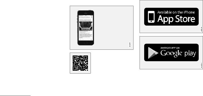
INTRODUCTION
||Using the search function
1.Tap the magnifying glass icon ( ) in the owner’s manual’s upper menu. A keyboard will appear at the bottom of the screen.
2.Enter a word, e.g., «seat belt.»
>Suggested articles will be displayed as more characters are entered.
3.Confirm by tapping the article. To leave search mode tap the up-arrow next to the search box.
Related information
•On-board digital owner’s manual (p. 15)
•Using the center display keyboard (p. 47)
Owner’s manual in mobile devices
Owner’s information mobile app1 can be downloaded from the App Store and Google Play and is adapted for both cell phones and tablets.
These apps also contain videos and interior/ exterior hotspot views of the vehicle that you can click on for additional information.
This QR code will take you directly to the app or you can search for «Volvo manual» in the App Store or Google Play.
The app contains videos and exterior/interior views of the vehicle with certain components/ functions highlighted in hotspots, which lead directly to related information. It is easy to navigate between the various categories and articles and the contents are searchable.
The mobile app is available at the App Store and Google Play
1 Certain models and mobile devices
18
Related information
•Using the owner’s manual (p. 20)
•Additional information about your vehicle (p. 19)
Additional information about your vehicle
Volvo Cars’ website and support site provide additional information about your vehicle.
Support on the Internet
Go to support.volvocars.com to visit the site, which is available in most markets.
The information on the support site is searchable and is grouped into different categories. It includes support for e.g., Internet-based services and functions, Volvo On Call, the navigation system and apps. Video and step-by-step instructions explain various procedures such as how to connect the vehicle to the Internet via a cell phone.
Downloadable information
Maps
Sensus Navigation system maps can be downloaded from the support site.
Mobile apps
Beginning with model year 2014, the owner’s manual is available in the form of an app for certain Volvo models. The Volvo On Call app can also be found here.
Owner’s manuals for earlier model Volvos
Owner’s manuals for earlier model Volvos are available in PDF format. Quick Guides and supplements can also be found on the support site.
INTRODUCTION
Select a model and a model year and download the desired information.
Contact
Contact information for customer support and the nearest Volvo retailer are available on the site.
Related information
•Using the owner’s manual (p. 20)
•On-board digital owner’s manual (p. 15)
•Volvo ID (p. 25)
19

INTRODUCTION
Using the owner’s manual
Reading your owner’s manual is a good way of familiarizing yourself with the features and systems in your vehicle.
On-board owner’s manual
Reading the owner’s manual is a good way to become familiar with your vehicle and to learn to utilize the features and functions that it offers. Pay particular attention to the warnings provided.
Volvo reserves the right to make model changes at any time, or to change specifications or design without notice and without incurring obligation.
© Volvo Car Corporation
Printed owner’s information
We advise keeping printed owner’s information in the vehicle for quick access to necessary information and how to contact Volvo if help is required.
Illustrations
Some of the illustrations and images used in your owner’s information may be generic and are intended to provide a general view or an example of a certain feature or function. The features or functions in the illustrations may differ slightly from the equipment in your vehicle depending on the level of instrumentation or market.
Options and accessories
Optional or accessory equipment described in this manual is indicated by an asterisk.
Optional or accessory equipment may not be available in all countries or markets. Please note that some vehicles may be equipped differently, depending on special legal requirements.
Contact your Volvo retailer for additional information.
Footnotes
Certain pages of this manual contain information in the form of footnotes at the bottom of the page. This information supplements the text that the footnote number refers to (a letter is used if the footnote refers to text in a table).
Messages
There are several displays in the vehicle that show messages generated by various systems and functions in the vehicle. The appearance of these texts differs slightly from normal texts (for example: Phone, Accept).
Decals
There are various types of decals in the vehicle whose purpose is to provide important information in a clear and concise way. The importance of these decals is explained as follows, in descending order of importance.
Risk of injury
Black ISO symbols on a yellow warning background, white text/image on a black background. Decals of this type are used to indicate potential danger. Ignoring a warning of this type could result in serious injury or death.
20
Risk of damage to the vehicle
White ISO symbols and white text/image on a black or blue warning background and space for a message. If the information on decals of this type is ignored, damage to the vehicle could result.
Information
White ISO symbols and white text/image on a black background. These decals provide general information.
NOTE
The decals shown in the Owner’s Manual are examples only and are not intended to be reproductions of the decals actually used in the vehicle. The purpose is to give an indication of how they look and their approximate location in the vehicle. The applicable information for your particular vehicle can be found on the respective decals in the vehicle.
Types of lists
Procedures
Procedures (step-by-step instructions), or actions that must be carried out in a certain order, are arranged in numbered lists in this manual.
If there is a series of illustrations associated with step-by-step instructions, each step in the procedure is numbered in the same way as the corresponding illustration.
Lists in which letters are used can be found with series of illustrations in cases where the order in which the instructions are carried out is not important.
Arrows with or without numbers are used to indicate the direction of a movement.
INTRODUCTION
Arrows containing letters are used to indicate movement.
If there are no illustrations associated with a step-by-step list, the steps in the procedure are indicated by ordinary numbers.
Position lists
Red circles containing a number are used in general overview illustrations in which certain components are pointed out. The corresponding number is also used in the position list’s description of the various components.
Bullet lists
Bullets are used to differentiate a number of components/functions/points of information that can be listed in random order.
For example:
•Coolant
•Engine oil
Related information
Related information offers references to articles containing information associated with the information that you are currently reading.
Continues on next page
} }This symbol can be found at the lower right corner to indicate that the current topic continues on the following page.
}}
21
INTRODUCTION
||Continuation from previous page
|| This symbol can be found at the upper left corner to indicate that the current topic is a continuation from the previous page.
Related information
•On-board digital owner’s manual (p. 15)
•Owner’s manual in mobile devices (p. 18)
•Additional information about your vehicle (p. 19)
Crash event data
This vehicle is equipped with an event data recorder (EDR). The main purpose of an EDR is to record, in certain crash or near crash-like situations, such as an air bag deployment or hitting a road obstacle, data that will assist in understanding how a vehicle’s systems performed. The EDR is designed to record data related to vehicle dynamics and safety systems for a short period of time, typically 30 seconds or less. The EDR in this vehicle is designed to record such data as:
•How various systems in your vehicle were operating;
•Whether or not the driver and passenger safety belts were buckled/fastened;
•How far (if at all) the driver was depressing the accelerator and/or brake pedal; and,
•How fast the vehicle was traveling.
These data can help provide a better understanding of the circumstances in which crashes and injuries occur.
EDR data are recorded by your vehicle only if a non-trivial crash situation occurs; no data are recorded by the EDR under normal driving conditions and the EDR never registers who is driving the vehicle or the location of a crash or a near crash-like situation. However, other parties, such as law enforcement, could combine the EDR data with the type of personally identifying data rou-
tinely acquired during a crash investigation. To read data recorded by an EDR, special equipment is required, and access to the vehicle or the EDR is needed.
Furthermore, your vehicle is equipped with a number of computers whose task is to continuously control and monitor the vehicle’s operation. They can also register some of this information during normal driving conditions, most importantly if they detect a fault relating to the vehicle’s operation and functionality or upon activation of the vehicle’s active safety systems (e.g. City Safety and the auto-brake function). Some of the registered information is required by technicians when carrying out service and maintenance to enable them to diagnose and rectify any faults that have occurred in the vehicle and to enable Volvo to fulfill legal and other regulatory requirements. Information thus registered in the vehicle is registered in the vehicle’s computers until the vehicle is serviced or repaired. In addition to the above, the registered information may – on an aggregated basis – be used for research and product development purposes in order to continuously improve the safety and quality of Volvo vehicles.
For additional information, contact:
In the United States
Volvo Car USA, LLC
Customer Care Center
1 Volvo Drive, P.O. box 914
22

Rockleigh, New Jersey 07647 1-800-458-1552 www.volvocars.com/us
In Canada
Volvo Car Canada Ltd.
Customer Care Centre
9130 Leslie Street
Richmond Hill, Ontario L4B 0B9 1-800-663-8255 www.volvocars.com/ca
Options, accessories and the Onboard Diagnostic (OBDII) socket
We strongly recommend that Volvo owners install only genuine, Volvo-approved accessories, and that accessory installations be performed only by a trained and qualified Volvo service technician.
Optional or accessory equipment described in this manual is indicated by an asterisk.
Optional or accessory equipment may not be available in all countries or markets. Please note that some vehicles may be equipped differently, depending on special legal requirements.
Contact your Volvo retailer for additional information.
INTRODUCTION
NOTE
•Do not export your Volvo to another country before investigating that country’s applicable safety and exhaust emission requirements. In some cases it may be difficult or impossible to comply with these requirements. Modifications to the emission control system(s) may render your Volvo not certifiable for legal operation in the U.S., Canada and other countries.
•All information, illustrations and specifications contained in this manual are based on the latest product information available at the time of publication. Please note that some vehicles may be equipped differently, depending on market-specific adaptations or special legal requirements. Optional equipment described in this manual may not be available in all markets.
•Some of the illustrations shown are generic and are intended as examples only, and may not depict the exact model for which this owner’s information is intended.
•Volvo reserves the right to make model and product changes at any time, or to change specifications or design without notice and without incurring obligation.
}}
23
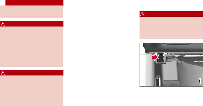
INTRODUCTION
|| WARNING
If your vehicle is involved in an accident, unseen damage may affect its drivability and safety.
WARNING
CALIFORNIA proposition 65
Engine exhaust, some of its constituents, and certain vehicle components contain or emit chemicals known to the state of California to cause cancer, and birth defects or other reproductive harm. In addition, certain fluids contained in vehicles and certain products of component wear contain or emit chemicals known to the State of California to cause cancer, and birth defects or other reproductive harm.
WARNING
Certain components of this vehicle such as air bag modules, seat belt pretensioners, adaptive steering columns, and button cell batteries may contain Perchlorate material. Special handling may apply for service or vehicle end of life disposal.
See www.dtsc.ca.gov/hazardouswaste/ perchlorate.
•Genuine Volvo accessories are tested to ensure compatibility with the performance, safety, and emission systems in your vehicle.
Additionally, a trained and qualified Volvo service technician knows where accessories may and may not be safely installed in your Volvo. In all cases, please consult a trained and qualified Volvo service technician before installing any accessory in or on your vehicle.
•Accessories that have not been approved by Volvo may or may not be specifically tested for compatibility with your vehicle. Additionally, an inexperienced installer may not be familiar with some of your car’s systems.
•Any of your car’s performance and safety systems could be adversely affected if you install accessories that Volvo has not tested, or if you allow accessories to be installed by someone unfamiliar with your vehicle.
•Damage caused by unapproved or improperly installed accessories may not be covered by your new vehicle warranty. See your Warranty and Service Records Information booklet for more warranty information. Volvo assumes no responsibility for death, injury, or expenses that may result from the installation of nongenuine accessories.
Connecting equipment to the On-board Diagnostic (OBDII) socket
WARNING
Volvo Cars takes no responsibility for the consequences of connecting non-authorized equipment to the On-board Diagnostic (OBDII) socket. This socket should only be used by a trained and qualified Volvo service technician.
The diagnostic socket OBDII under the dashboard on the driver’s side
24

Type approval
USA
FCC ID: 2AGKKACUII-06
This device complies with Part 15 of the FCC rules. Operation is subject to the following two conditions:
(1)This device may not cause harmful interference, and
(2)this device must accept any interference received, including interference that may cause undesired operation.
WARNING
Changes or modifications not expressly approved by the party responsible for compliance could void the user’s authority to operate the equipment.
Canada
IC: 20839-ACUII06
This device complies with Industry Canada licence-exempt RSS standard(s). Operation is subject to the following two conditions:
(1)this device may not cause interference, and
(2)This device must accept any interference received, including interference that may cause undesired operation.
Volvo ID
A Volvo ID can be used to access a number of online services2
Creating a Volvo ID
A Volvo ID can be created in two ways:
Using the Volvo ID app
1.If you have not already done so, download the Volvo ID app from the Download Center.
2.Start the app and register a personal email address.
3.Follow the instructions that will be sent automatically to this email address.
>A Volvo ID has now been created and has been automatically registered to the vehicle. The Volvo ID services available can now be used.
Using the Volvo On Call app
1.Download the latest version of the Volvo On Call app to your cell phone from e.g., the App Store, Windows Phone or Google Play.
2.Start the app and create a Volvo ID on the start page.
3.Register a personal email address and then follow the instructions that will be sent automatically to this address.
2 These services vary and may be subject to change. Consult your Volvo retailer.
INTRODUCTION
Registering your Volvo ID to the vehicle
If your Volvo ID was created using the Volvo On Call mobile app, the ID has to be registered to the vehicle:
1.With the vehicle connected to the Internet, download the Volvo ID app from the Download Center in the center display’s App view. See also the article «Downloading, updating and uninstalling apps.»
2.Start the app and enter your Volvo ID.
3.Follow the instructions that will be sent automatically to the email address linked to your Volvo ID.
>Your Volvo ID is now registered to the vehicle and the Volvo ID services available can be used.
Advantages of having a Volvo ID
•Only one user name and password are required to access online services.
•If you change a user name or password for one of the online service (e.g., Volvo On Call), it/they will also be automatically changed for the other services.
Related information
•Downloading, updating and uninstalling apps (p. 454)
•Connecting to the Internet (p. 450)
25
INTRODUCTION
Volvo and the environment
Volvo is committed to the well-being of its customers. As a natural part of this commitment, we care about the environment in which we all live. Concern for the environment means an everyday involvement in reducing our environmental impact.
Volvo’s environmental activities are based on a holistic view, which means we consider the overall environmental impact of a product throughout its complete life cycle. In this context, design, production, product use, and recycling are all important considerations. In production, Volvo has partly or completely phased out several chemicals including CFCs, lead chromates, asbestos, and cadmium; and reduced the number of chemicals used in our plants 50% since 1991.
Volvo was the first in the world to introduce into production a three-way catalytic converter with a Lambda sond, now called the heated oxygen sensor, in 1976. The current version of this highly efficient system reduces emissions of harmful substances (CO, HC, NOx) from the exhaust pipe by approximately 95 – 99% and the search to eliminate the remaining emissions continues. Volvo is the only automobile manufacturer to offer CFC-free retrofit kits for the air conditioning system of all models as far back as the 1975 model 240. Advanced electronic engine controls and cleaner fuels are bringing us closer to our goal. In addition to continuous environmental
refinement of conventional gasoline-powered internal combustion engines, Volvo is actively looking at advanced technology alternative-fuel vehicles.
When you drive a Volvo, you become our partner in the work to lessen the car’s impact on the environment. To reduce your vehicle’s environmental impact, you can:
•Maintain proper air pressure in your tires. Tests have shown decreased fuel economy with improperly inflated tires.
•Follow the recommended maintenance schedule in your Warranty and Service Records Information booklet.
•Drive at a constant speed whenever possible.
•See a trained and qualified Volvo service technician as soon as possible for inspection if the check engine (malfunction indicator) light illuminates, or stays on after the vehicle has started.
•Properly dispose of any vehicle-related waste such as used motor oil, used batteries, brake pads, etc.
•When cleaning your vehicle, please use genuine Volvo car care products. All Volvo car care products are formulated to be environmentally friendly.
Related information
•Driving economically (p. 399)
IntelliSafe—driver support
IntelliSafe is Volvo’s philosophy regarding vehicle safety. It encompasses a number of systems, both standard and optional, that are designed to help make driving and traveling in a Volvo safer.
Support
Systems that help make driving safer are an integral part of IntelliSafe. These include optional features such as Adaptive Cruise Control* that helps maintain a set distance to a vehicle ahead, Park Assist Pilot*, which assists in parking the vehicle, Cross Traffic Alert*, Blind Spot Information*, etc.
Accident prevention
Systems such as City Safety are designed to automatically apply the brakes in situations in which the driver does not have time to react.
Lane Keeping Aid* alerts the driver if the vehicle inadvertently crosses a lane’s/road’s side marker line.
Protection
The vehicle is equipped with e.g., seat belt pretensioners that pull the seat belts taut in critical situations when there is a collision risk and numerous airbags designed to help provide cushioning if certain types of collisions should occur.
Related information
•Adaptive Cruise Control (ACC)* (p. 270)
•Park Assist Pilot (PAP)* (p. 356)
INTRODUCTION
•High and low beam headlights (p. 141)
•Cross Traffic Alert (CTA)* (p. 321)
•Blind Spot Information (BLIS)* (p. 319)
•City Safety™ (p. 307)
•Driving lane assistance (p. 330)
•Airbag system (p. 67)
•Roll stability control (RSC) (p. 253)
•Seat belts (p. 62)
•General safety information (p. 58)
* Option/accessory. 27

INTRODUCTION
Sensus
Sensus is the core of your personal Volvo experience and provides information, entertainment and features that make owning your vehicle easier.
This is Sensus
Sensus provides an intelligent interface and Internet-connected service with an intuitive navigation structure that offers access to relevant information when it is needed, with minimal distractions.
Sensus also includes all of your vehicle’s solutions relating to entertainment, connecting to the Internet, navigation and the user interface between the driver and the vehicle. Sensus makes communication between you, the vehicle and the digital world around you possible.
28

INTRODUCTION
Information when it’s needed, where it’s needed
Information is presented in different displays depending on how it should be prioritized (generic illustration)
Head-up-display* |
ately, such as traffic warnings, speed information |
Instrument panel |
|||||
|
and navigation. Road sign information and incom- |
|||||||
|
ing phone calls are also displayed here. The |
|||||||
|
head-up display is controlled from the right-side |
|||||||
|
steering wheel keypad and the center display. |
|||||||
|
The head up-display presents types of informa- |
12″ instrument panel |
|
|
}} |
||
|
tion that the driver should be aware of immedi- |
||
* Option/accessory. 29

INTRODUCTION
||
8″ instrument panel
The instrument panel displays information such as speed, an incoming phone call or the track that is currently playing. It is controlled using both steering wheel keypads.
Center display
Many of the vehicle’s main functions are controlled from the center display, a touchscreen that reacts to taps or other gestures. The number of physical buttons is thereby minimized. The screen can be operated with or without gloves.
The center display is used to control e.g., the climate and infotainment systems and to adjust the power seats*. The information shown here can be dealt with by the driver or the front seat passenger.
Voice control system
The voice control system enables the driver to operate certain vehicle functions without
removing his/her hands from the steering wheel and it understands natural speech. Use voice commands to e.g.,
play a track on the infotainment system, make a phone call, raise the passenger compartment temperature or to read a text message.
For additional information about all of the functions/system, see the respective articles in the on-board owner’s manual or the printed supplement.
Related information
•Using the center display (p. 34)
•Center display overview (p. 32)
•Navigating in the center display’s views (p. 38)
•Head-up display (HUD)* (p. 117)
•Instrument panel (p. 97)
•Voice control (p. 120)

Owner’s manual and the environment
The wood pulp in Volvo’s printed owner’s information comes from FSC® (Forest Stewardship Council®) certified forests and other responsible sources.
FSC®
The symbol above indicates that the wood pulp is FSC® certified.
Related information
•Volvo and the environment (p. 26)
3 This symbol is not shown on the windshield or panoramic roof.
INTRODUCTION
Glass
Laminated glass
The windshield and panoramic roof* are made of laminated glass, which is reinforced to help prevent break-ins and to provide additional soundproofing. Laminated glass is optional for the other side windows.
Laminated glass symbol3
Related information
•Laminated panoramic roof* (p. 159)
•Power windows (p. 153)
•Defrosting windows and mirrors (p. 194)
•Using sun curtains* (p. 155)
•Rearview mirror (p. 157)
•Power windows (p. 153)
•Head-up display (HUD)* (p. 117)
•Activating/deactivating the rain sensor (p. 151)
•Windshield and headlight washers (p. 152)
•Tailgate window wiper and washer (p. 153)
* Option/accessory. 31

INTRODUCTION
Center display overview
Many of the vehicle’s functions are controlled from the center display.
Three of the center display’s basic views. Swipe to the right/left to access the Function/App view (generic illustration)
32

Function view: vehicle functions can be activated/deactivated by tapping. Certain functions are called «trigger functions», which open settings windows, e.g., Camera and parking functions. Settings for the head-up display* are also started from Function view but the actual interaction is controlled from the steering wheel keypad buttons and the instrument panel.
Home view: the initial view shown when the center display is started.
App (Application) view: shows apps that have been downloaded (third-party apps) as well as ones for integrated functions such as FM radio. Tap an icon to open the app.
Status bar: vehicle activities are shown at the top of the screen. Network/connection information is shown on the left side of the bar.
Media-related information, the clock and information about background activities are shown to the right.
Top view: pull down the tab to open Top view. From here, you can access Settings, Owner’s manual and stored messages.
Navigation: leads to map navigation. Tap the sub-view to expand it.
Media: the most recently used media-related apps. Tap the sub-view to expand it.
Phone: used to access phone-related functions. Tap the sub-view to expand it.
INTRODUCTION
The extra sub-view: the most recently used apps/vehicle functions that do not belong in any of the other sub-views are listed here. Tap the sub-view to expand it.
Climate bar: information and direct access to settings such as temperature, seat heating* and blower speed. Tap the symbol at the center of the Climate bar to open Climate view for additional settings.
Related information
•Using the center display (p. 34)
•Function view buttons (p. 45)
•Symbols in the center display status bar (p. 43)
•Settings view (p. 170)
•Media player (p. 429)
•Phone (p. 442)
•Climate system controls in the center display (p. 187)
•Cleaning the center display (p. 538)
* Option/accessory. 33

INTRODUCTION
Using the center display
Many of the vehicle’s functions can be controlled and settings can be made from the screen in the center console, referred to in this owner’s information as the center display, which is a touchscreen.
Using the center display’s touchscreen functionality
Two people can interact with the screen at the same time, e.g., to adjust the temperature for the driver and passenger sides.
The screen reacts differently depending on whether the user taps, drags or swipes on the screen. This makes it possible to move between views, mark objects, scroll in lists and move apps by touching the screen in various ways. The following table lists the gestures that can be used on the screen:
An infrared film on the screen enables it to react if a finger is directly in front of the screen (but not actually touching it). This makes it possible to use the screen while wearing gloves.
CAUTION
Do not touch the screen with sharp objects because this could cause scratches.
|
Procedure |
Gesture |
Result |
||
|
Tap once. |
Marks an object, confirms a selection or activates a function. |
|||
|
Double-tap. |
Zooms in on an object such as a map. |
|||
|
Press and hold. |
«Grabs» an object so that it can be dragged. Press and hold on the screen and drag the object to the desired |
|||
|
position. |
||||
|
Tap with two fingers. |
Zooms out from an object such as a map. |
|||
34

INTRODUCTION
|
Procedure |
Gesture |
Result |
||
|
Drag |
Moves between screen views, scrolls in a list, text or a view. Press and hold to drag apps or objects in a list. |
|||
|
Swipe |
Moves between screen views, scrolls in a list, text or a view |
|||
|
Pinch |
Zooms out. |
|||
}}
35

INTRODUCTION
||Turning off and reactivating the center display
Home button for the center display
When the center display is turned off, the screen goes dark to avoid disturbing the driver. However, the climate bar remains visible and apps or other functions connected to the display remain active.
1.Press and hold the Home button below the screen.
>The screen will go dark. However, the climate bar remains visible and apps or other functions connected to the display remain active. The screen can also be cleaned while it is turned off.
2.Reactivate by pressing the Home button briefly.
>The view that was displayed when the screen was turned off will be displayed again.
NOTE
•The display cannot be turned off while a message requiring action is on the screen.
•The display turns off automatically when the ignition is switched off and the driver’s door is opened.
Returning to Home view
1.Press the Home button briefly.
>The most recent Home view mode will be displayed.
2.Press again briefly.
>All of the Home view’s sub-views will return to standard mode.
NOTE
From Home view’s standard mode, press the Home button to start animated on-screen instructions describing how to display the various views.
Moving apps and vehicle function buttons
Apps and function buttons can be moved and organized in their respective views.
1.Press and hold an app/button.
>The app/button will change size and become transparent. It can then be moved.
2.Drag the app/button to an available position in the view.
A maximum of 48 lines can be utilized for placing apps/buttons. To move an app/button outside of the visible view, drag it to the bottom of the view. A new line will then be added where the app/ button can be placed (this line may not be visible). Swipe the screen to scroll up or down in the view to display information that may be outside of the view.
Scrolling in lists, articles or views
A scroll indicator on the screen shows that it is possible to scroll up or down in the view. Press the indicator and move it up or down or swipe up or down anywhere in the view.
36

The scroll indicator on the right side of the center display
Using center display controls
Temperature control4
INTRODUCTION
Digital controls are available for many of the vehicle’s functions. For example, to set the temperature:
•Drag the control to the desired temperature
•Tap +/− to raise or lower the temperature incrementally, or
•Tap the desired temperature on the control
Related information
•Navigating in the center display’s views (p. 38)
•Settings view (p. 170)
•Sensus (p. 28)
•Downloading, updating and uninstalling apps (p. 454)
•Using the center display keyboard (p. 47)
4 Generic illustration. The temperature in your vehicle may be set to degrees Fahrenheit.
37

INTRODUCTION
Navigating in the center display’s views
There are 5 different basic views in the center display: Home view, Top view, Climate view, App view and Function view. The display is activated automatically when the driver’s door is opened.
Home view
Home view is displayed when the screen is activated. It consists of four sub-views: Navigation, Media, Phone and an extra sub-view. The extra sub-view contains the most recently used app/ vehicle function that is not related to the other three sub-views. For example, if the most recently
used app/vehicle function is a music app, the Media sub-view will be displayed.
The sub-views display brief information about the respective apps.
The first time the vehicle is started, some of the Home view’s sub-views will not contain any information.
NOTE
In Home view’s standard mode (reached by pressing the Home button briefly), an animation explaining how to access the different views will be shown on the screen.
NOTE
When the vehicle is moving:
•Some functions (using the center display keyboard, etc.) may be disabled.
•Certain texts (e.g., those generated by apps) will be truncated to three lines. Tap the Read out button to have the entire text read aloud.
•Text messages will be truncated to one line. Tap the Read out button to have the entire text read aloud.
38
![]()
INTRODUCTION
Expanding a sub-view from the standard view
Standard view and an expanded sub-view in the center display
}}
39

INTRODUCTION
||Expanding a sub-view:
–To expand sub-view one, two or three: tap the screen anywhere in the sub-view. When a sub-view is expanded, the Home view’s fourth sub-view will temporarily not be displayed. The other two views will be minimized and will only show limited information. Tapping the fourth sub-view will minimize the other three sub-views and they will only show limited information.
Expanding a sub-view provides access the respective apps’ basic functions.
Closing an expanded sub-view:
–A sub-view can be closed in three different ways:
•Tap the upper section of the expanded sub-view.
•Tap one of the other sub-views (which will then open in expanded view).
•Press the Home button below the center display briefly.
Opening/closing a sub-view in full-screen mode
The extra sub-view and the Navigation sub-view can be opened in full-screen mode to show additional information and possible settings.
In expanded mode, open the app in full-screen mode by tapping the symbol.
Tap on the symbol or the Home button below the screen to return to the expanded view.
It is always possible to return to Home view by pressing the Home button. Press the Home button twice to return to Home view’s standard view from full-screen.
Home button for the center display
Status bar
Current vehicle activities are shown in the status bar at the top of the screen. Network and connection information is shown to the left. Brief information about currently running apps and the clock are shown to the right.
Top view
The top view has a tab at the center of the status bar. Pull down (expand) the Top view by swiping the tab downward.
Top view when expanded
Top view provides access to:
•Settings
•Owner’s manual
•Profile
•The vehicle’s stored messages
40

To leave (minimize) Top view, tap the screen outside of this view or tap at the bottom of Top view and swipe upward. The views behind will become visible again. Top view is not available when the ignition is being started/switched off or when a message is displayed on the screen.
Going to Top view from an app
To pull down Top view when an app is running (e.g., FM radio):
•Tap FM Radio Settings to display these settings.
•Tap Owner’s manual to open an article related to the specific app.
This applies only to your vehicle’s factoryinstalled apps. This is not possible for thirdparty apps that have been downloaded.
Climate view
The climate bar, where the most common climate system settings can be made, is located at the bottom of the screen and is always visible.
Tap the symbol at the center of the climate bar to open Climate view for access to additional climate system settings.
Tap the symbol to close Climate view and return to a previous view.
|
INTRODUCTION |
|||
App view |
When applicable, swipe downward to scroll in the |
||
|
list of apps (depending on the number of apps |
|||
|
currently running). |
|||
|
To move an app, press and hold it. It will become |
|||
|
slightly bigger and transparent and can then be |
|||
|
dragged to the desired position and released. |
|||
|
Return to Home view by swiping the screen from |
|||
|
left to right or by pressing the Home button. |
|||
Function view |
|||
App view (generic illustration)
Swipe the screen from right to left to access App view from Home view. This displays factory-instal- led apps such as FM as well as any apps that have been downloaded. Brief information will be displayed for certain apps, for example missed phone calls, etc.
Tap an app to open it.
Function view (generic illustration)
}}
41
INTRODUCTION
||Swipe the screen from left to right to access Function view from Home view. From Function view, you can activate/deactivate various vehicle functions such as Drive Modes, Speed Sign Assist and Park Assist.
When applicable, swipe upward to scroll in the list of functions (depending on the number of functions).
Activate/deactivate a function by tapping its button. Certain functions will open in their own windows.
To move a function button, press and hold it. It will become slightly smaller and transparent and can then be dragged to the desired position and released.
Related information
•Using the center display (p. 34)
•Center display overview (p. 32)
•Function view buttons (p. 45)
•Symbols in the center display status bar (p. 43)
•Changing settings in different types of apps (p. 52)
•Climate system controls (p. 186)
42

Symbols in the center display status bar
The following table provides an overview of the symbols used in the center display’s status bar.
The status bar shows current vehicle activities and in certain cases, also their status. Due to limited space in the status bar, not all symbols will be displayed at all times.
Symbol Meaning
Roaming activated.
Cell phone network signal strength.
Bluetooth device connected.
Bluetooth activated but no device connected.
Connected to a Wi-Fi network.
Tethering activated. (Wi-Fi hotspot).
Vehicle modem activated.
Action in progress.
Preconditioning timer active (hybrid models only)
Symbol Meaning
Audio source being played.
Audio source paused.
Phone call in progress.
Audio source muted.
News broadcasts from current radio stationA.
Traffic information being receivedA.
Clock.
A Not available in all markets.
Related information
•Navigating in the center display’s views (p. 38)
•Indicator symbols in the instrument panel (p. 101)
•Warning symbols in the instrument panel (p. 103)
•Messages in the instrument panel and center display (p. 113)
INTRODUCTION
Changing center display settings
The center display activates automatically when the driver’s door is opened. Settings can be made for e.g., sounds, background and themes.
Turning off or changing the volume of center display sounds
System sounds in the center display can be turned off or their volume can be changed:
1.Tap Settings in the center display’s Top view.
2.Tap Sound  System Volumes.
3.Pull the control under Screen Touch to the desired level to change volume or turn off the sound for tapping the screen or Keypad Touch.
Changing the screen’s appearance (theme)
1.Tap Settings in the center display’s Top view.
2.Tap My Car  Displays
  Display Themes.
3.Select a theme, e.g., Minimalistic or
Chrome Rings.
In addition, the settings: Normal and Bright can also be selected. For Normal, the screen’s background is dark and the text is light. This is the
default setting. If Bright is selected, the back-
}}
43
INTRODUCTION
||ground will be light and the text will be dark, which can increase readability in strong ambient lighting.
These alternatives are always available and do not shift automatically according to changes in ambient lighting.
Related information
•Using the center display (p. 34)
•Sensus (p. 28)
•Settings view (p. 170)
•Cleaning the center display (p. 538)
44

Function view buttons
The Function view, which is one of the center display’s basic views, contains all of the vehicle’s
on-screen function buttons. From the Home view, swipe from left to right on the screen to come to the Function view.
INTRODUCTION
Different types of buttons
There are three different types of vehicle function buttons as listed in the following table.
|
Type of button |
Functions |
Vehicle function affected |
|
|
Function buttons |
Have On/Off modes. |
Most of the buttons in the function view are |
|
|
An LED indicator light to the left of the button’s icon will illuminate when a function is |
function buttons. |
||
|
active. Press the button to turn the function on or off. |
|||
|
Start buttons |
Do not have On/Off modes. |
• |
Camera. |
|
Pressing a start button opens a function’s window, e.g., a window for adjusting the |
• |
Headrest fold. |
|
|
driver’s seat. |
• Functions for folding down a seat. |
||
|
• Head-up display adjustments. |
|||
|
Parking buttons |
Have On/Off and scanning modes. |
• |
Park In. |
|
Similar to function buttons but have an additional parking scanning mode. |
• |
Park Out. |
|
Button modes
A function is deactivated (off) when the LED indicator is
A function is activated (on) when the LED indicator is off green
When a function or parking button’s LED indicator is green, the function is activated. When a function is initially activated, an additional text will be displayed (certain functions only) in the button for approx. 5 seconds, after which the button will be displayed with the LED indicator illuminated.
Press the button briefly to deactivate the function.
}}
45

INTRODUCTION
||
The yellow triangle indicates that the function is not working correctly
Related information
•Center display overview (p. 32)
•Navigating in the center display’s views (p. 38)
•Categories in Settings view (p. 171)
46

INTRODUCTION
Using the center display keyboard
A keyboard can be used on the center display to enter characters and search for e.g., destinations using the navigation system, adding contacts in phone book, etc. It is also possible to use handwriting on the screen.
Entering text using the keyboard
The keyboard will only appear at the bottom of the center display in situations when it is possible to write on the screen.
NOTE
The keyboard cannot be used if the vehicle is moving.
}}
47

Keyboard function buttons (the appearance may vary depending on language settings, context, etc.)
|
Field for possible search hits. The word |
word to select it. The keyboard may not sup- |
|
changes as new letters are added. Scroll in |
port all language selections, in which case |
|
the list using the left/right arrows. Tap a |
this line on the screen will not be displayed. |
The characters that can be entered are lan- guage-dependent (see point 7). Tap a character to enter it.
48
 Loading…
VOLVO V90 CROSS COUNTRY Owner’s Manuals and Service Manuals for online browsing and download. Search through 1469 VOLVO Manuals online for free. CarManualsOnline.info is the largest free online database of VOLVO user manuals.
VOLVO, Select Model:
All, 240, 400, 700, 850, 900, 940, 960, C30, C40 RECHARGE PURE ELECTRIC, C60 RECHARGE, C70, C70 CONVERTIBLE, CHV60 RECHARGE, S40, S60, S60T8, S60 CROSS COUNTRY, S60 INSCRIPTION, S60 RECHARGE, S60 T8, S60 TWIN ENGINE, S70, S80, S90, S90 RECHARGE, S90 T8, S90 TWIN ENGINE, V4, V50, V60, V60 CROSS COUNTRY, V60 RECHARGE, V60 T8, V60 TWIN ENGINE, V70, V70/XC70, V90, V90 CROSS COUNTRY, XC40, XC40 RECHARGE, XC40 RECHARGE PURE ELECTRIC, XC60, XC60 RECHARGE, XC60 T8, XC60 TWIN ENGINE, XC70, XC90, XC90 EXCELLENCE, XC90 RECHARGE, XC90 T8, XC90 TWIN ENGINE, XC90 TWIN ENGINE HYBRID
VOLVO V90 CROSS COUNTRY, Select Model:
- VOLVO V90 CROSS COUNTRY 2017
- VOLVO V90 CROSS COUNTRY 2018
- VOLVO V90 CROSS COUNTRY 2019
- VOLVO V90 CROSS COUNTRY 2020
- VOLVO V90 CROSS COUNTRY 2021
- VOLVO V90 CROSS COUNTRY 2022
List of All VOLVO V90 CROSS COUNTRY Manuals:
Recent Searches in VOLVO Manuals
power steering VOLVO XC60 2010 Owner´s Manual, charging VOLVO XC60 2010 Owner´s Manual, service VOLVO XC60 2015 Owner´s Manual, interior lights VOLVO XC60 2010 Owner´s Manual, remote control VOLVO XC60 2015 Owner´s Manual, spark plugs VOLVO S90 2017 Owner´s Manual, compression ratio VOLVO XC60 2010 Owner´s Manual, radio antenna VOLVO S90 2017 Owner´s Manual, oil viscosity VOLVO S90 2017 Owner´s Manual
The Volvo V90 Cross Country, which came out in 2020, is a rough-and-tumble version of the V90 waggon. It combines the V90’s practicality and style with better off-road skills and a more daring look. The V90 Cross Country is made in the same style as the V90, but it has some features that make it look more tough and strong. It has a higher ground clearance, protective body cladding, and front and back bumpers that look different from each other. These design features not only make the car better at going off-road, but they also give it a unique and adventurous look. The V90 Cross Country comes standard with all-wheel drive, which gives it better grip and stability in a variety of driving situations. It can handle rough terrains, gravel roads, and bad weather, so it’s good for people who want to go on more exciting trips. When it comes to speed, the V90 Cross Country has a number of engine choices that offer a good mix of power and fuel economy. The engines make the cars easy to drive on and off the road with their smooth acceleration and quick handling. The engines that are available may be different based on the market and the model.
OWNER’S INFORMATION
Owner’s information is available in several different formats, both digital and printed. The Owner’s Manual is available on the vehicle’s center display, as a mobile app and on Volvo Cars’ support website. There is also a Quick Guide in the glove compartment, as well as a supplement to the Owner’s Manual containing information about e.g. fuses, specifications, etc. A printed Owner’s Manual can be ordered.
Volvo Cars support site
Go to support.volvocars.com and select your country. Owner’s Manuals are available here for viewing online and in PDF format. The support site also contains instructive videos and additional information and assistance concerning your vehicle and owning a Volvo. The website is available in most markets.
Printed information
The glove compartment contains a printed supplement to the Owner’s Manual1, which contains information on fuses and specifications as well as a summary of important and practical information. There is also a printed Quick Guide with useful information about the most commonly used features and functions in your vehicle. Other printed information may also be provided in the vehicle, depending on the equipment level, market, etc. A printed Owner’s Manual and accompanying supplement can also be ordered. Contact a Volvo retailer to order.
CAUTION
The driver is always responsible for operating the vehicle in a safe manner and adhering to all applicable laws and regulations. It is also important that the vehicle is operated, maintained, and serviced according to Volvo’s recommendations provided in the owner’s information. If the information in the center displays differs from the printed information, the printed information always takes precedence.
NOTE
Changing languages in the center display could mean that certain owners’ information will not comply with national or local laws and regulations. Do not change to a language you do not speak well, as it can be difficult to find your way back through the menu.
Owner’s Manual in the center display
A digital version of the Owner’s Manual is available in the vehicle’s center display2. The digital Owner’s Manual can be accessed from Top view and in certain cases, the con-textual Owner’s Manual can also be accessed from the Top view.
Using the search function in the Top menu
- Tap in the Owner’s Manual upper menu. A keyboard will appear at the bottom of the screen.
- Enter a search word, e.g. “seat belt”.
> Suggested articles and categories will be displayed as characters are entered. - Tap the article or category to read it.
Using the Owner’s Manual
To get to know your new vehicle, read the Owner’s Manual before driving it for the first time.
Reading your Owner’s Manual is a way to familiarize yourself with new features and functions, get advice on how to handle your vehicle in different situations, and to learn how to take advantage of everything your Volvo has to offer. Pay particular attention to the safety warnings provided in the Owner’s Manual. The intention of this owner’s information is to explain all of the possible features, functions, options and accessories included in a Volvo vehicle. It is not intended as an indication or guarantees that all of these features, functions and options are included in every vehicle. Some terminology used may not exactly match the terminology used in sales, marketing and advertising materials.
Volvo continuously works to develop and improve our products. Modifications can mean that information, descriptions and illustrations in the Owner’s Manual differ from the equip-ment in the vehicle. We reserve the right to make changes without prior notice. Do not remove this manual from the vehicle. If a problem should occur, you will not have the necessary information on where and how to get professional assistance.
NOTE
The decals shown in the Owner’s Manual do not claim to be exact reproductions of those found in the vehicle. The purpose is to show approximately how they look and about where they are located. The informa-tion that applies for your vehicle, in particular, is found on the decal on the vehicle.
Creating a Volvo ID using the Volvo On Call app
- Download the latest version of the Volvo On Call app to your phone, via e.g. App Store, Windows Phone or Google Play.
- Choose to create a Volvo ID.
- The website for creating a Volvo ID will open. Fill in the requested information.
- Check the box to accept the terms and conditions.
- Press the button to create your Volvo ID.
- An email will be sent to the address you have provided. Confirm that the address is correct.
> Your Volvo ID is now ready to be used.
When you drive a Volvo, you become our part-ner in the work to lessen the vehicle’s impact on the environment.
To reduce your vehicle’s environmental impact, you can:
- Maintain proper air pressure in your tires. Tests have shown decreased fuel economy with improperly inflated tires.
- Follow the recommended maintenance schedule in your Warranty and Service Records Information booklet.
- Drive at a constant speed whenever possible.
- See a trained and qualified Volvo service technician as soon as possible for inspection if the check engine (malfunctioning indicator) light illuminates, or stays on after the vehicle has started.
- Properly dispose of any vehicle-related waste such as used motor oil, used batteries, brake pads, etc.
- When cleaning your vehicle, please use genuine Volvo car care products. All Volvo car care products are formulated to be environmentally friendly.
IntelliSafe – driver support and safety
IntelliSafe is Volvo Cars’ philosophy regarding vehicle safety. IntelliSafe consists of a number of systems2 that are designed to help make driving safer, prevent accidents and protect passengers and other road users.
WARNING
The functions are supplementary aids –they cannot manage all situations in all conditions.
The driver is always responsible for ensur-ing that the vehicle is driven in a safe man-ner and in accordance with applicable traf-fic rules and regulations.
Support
IntelliSafe has the following functions designed to help the driver operate the vehicle more safely.
- Active high beam
- Tunnel detection
- Pilot Assist
- *Cross Traffic Alert
- *Blind Spot Information
- Park Assist*
- Park Assist Pilot*
- Park Assist Camera*
- Road Sign Information*
- Electronic Stability Control
- Roll Stability Control
- Cruise control
- Adaptive Cruise Control*
- Rear Collision Warning
- Driver Alert Control
- All Wheel Drive (AWD)3
Sensus provides an intelligent interface and Internet connection to the digital world. An intuitive navigation structure offers access to relevant assistance, information and entertainment when it is needed, without distracting the driver. Sensus includes all of the solutions in the vehicle related to entertainment, Internet connection, and navigation*, and serves as the user interface between the driver and the vehicle. Sensus is what makes communication between you, the vehicle, and the world around you possible.
FAQ
1. Q: What is the 2020 Volvo V90 Cross Country?
A: The 2020 Volvo V90 Cross Country is a luxury crossover wagon that combines ruggedness with elegant design and advanced features.
2. Q: How many people can the V90 Cross Country seat?
A: The V90 Cross Country typically seats five passengers.
3. Q: What engine options are available for the 2020 V90 Cross Country?
A: The 2020 V90 Cross Country offers various engine options, including turbocharged and supercharged four-cylinder engines, with power outputs ranging from around 250 to 316 horsepower.
4. Q: Is the V90 Cross Country all-wheel drive?
A: Yes, the V90 Cross Country comes standard with all-wheel drive, providing better traction and stability in various driving conditions.
5. Q: What type of transmission does it have?
A: The V90 Cross Country is equipped with an eight-speed automatic transmission.
6. Q: What are some notable features of the 2020 V90 Cross Country?
A: The 2020 V90 Cross Country boasts features like a panoramic sunroof, leather upholstery, advanced driver-assistance systems, a large infotainment touchscreen, and more.
7. Q: How much cargo space does the V90 Cross Country have?
A: The V90 Cross Country offers around 53.9 cubic feet of cargo space with the rear seats folded down.
8. Q: What is the starting price of the 2020 Volvo V90 Cross Country?
A: The starting price of the 2020 V90 Cross Country typically ranged from approximately $52,550 to $54,550.
9. Q: What are some available upgrade packages?
A: Volvo offers packages like the Advanced Package, Luxury Package, and Climate Package, which include features like adaptive cruise control, premium sound systems, and heated seats.
10. Q: What is the T6 engine in the V90 Cross Country?
A: The T6 engine refers to the 2.0-liter four-cylinder engine with both turbocharging and supercharging, producing higher power outputs compared to the standard turbocharged T5 engine.
11. Q: How is the safety rating of the 2020 V90 Cross Country?
A: The V90 Cross Country typically received high safety ratings from organizations like the National Highway Traffic Safety Administration (NHTSA) and the Insurance Institute for Highway Safety (IIHS).
12. Q: How does the V90 Cross Country compare to the regular V90 model?
A: The V90 Cross Country has a higher ground clearance and more rugged exterior elements, making it better suited for off-road and adverse weather conditions compared to the regular V90.
13. Q: What is the fuel economy of the 2020 V90 Cross Country?
A: The fuel economy of the V90 Cross Country varies based on the engine configuration, but it typically ranges from around 22 to 30 miles per gallon on the highway.
14. Q: Are there any technology features worth mentioning?
A: The V90 Cross Country offers a Sensus infotainment system with a large touchscreen, smartphone integration, navigation, and available Bowers & Wilkins premium audio.