-
Contents
-
Table of Contents
-
Troubleshooting
-
Bookmarks
Quick Links
DC-80/DC-80S/DC-80 PRO/DC-80
EXP/DC-85
Diagnostic Ultrasound System
Operator’s Manual
[Basic Volume]
Related Manuals for Mindray DC-80
Summary of Contents for Mindray DC-80
-
Page 1
DC-80/DC-80S/DC-80 PRO/DC-80 EXP/DC-85 Diagnostic Ultrasound System Operator’s Manual [Basic Volume]… -
Page 3: Table Of Contents
Contents Contents ……………………..i Intellectual Property Statement ………………….I Responsibility on the Manufacturer Party ………………I Warranty ……………………….II Exemptions ……………………… II Customer Service Department ………………..III Important Information ……………………IV About This Manual ……………………… IV Notation Conventions ……………………IV Operator’s Manuals ………………………
-
Page 4
Image Optimization ………………..5-1 Imaging Mode ……………………5-1 B Mode Image Optimization ………………..5-4 M Mode Image Optimization ………………..5-11 Color Mode Image Optimization ………………5-14 Power Mode Image Optimization ………………5-20 PW/CW Doppler Mode ………………….. 5-22 Color M Mode ……………………5-28 Anatomical M Mode …………………. -
Page 5
11 DICOM/HL7 ………………….11-1 11.1 DICOM Preset ……………………11-1 11.2 Verify Connectivity ………………….11-10 11.3 DICOM Services ………………….. 11-10 11.4 DICOM Media Storage ………………… 11-13 11.5 Structured Report ………………….11-14 11.6 DICOM Task Management ………………..11-15 12 Setup……………………12-1 12.1 System Preset ……………………12-1 12.2 ExamMode Preset …………………. -
Page 6
Appendix F Electrical Safety Inspection …………..F-1… -
Page 7: Contents
Contents of this manual are subject to change without prior notice. All information contained in this manual is believed to be correct. Mindray shall not be liable for errors contained herein or for incidental or consequential damages in connection with the furnishing, performance, or use of this manual.
-
Page 8: Warranty
PARTICULAR PURPOSE. Exemptions Mindray’s obligation or liability under this warranty does not include any transportation or other charges or liability for direct, indirect or consequential damages or delay resulting from the improper use or application of the product or the use of parts or accessories not approved by Mindray or repairs by people other than Mindray authorized personnel.
-
Page 9: Customer Service Department
Customer Service Department Manufacturer: Shenzhen Mindray Bio-Medical Electronics Co., Ltd. Address: Mindray Building, Keji 12th Road South, High-tech industrial park, Nanshan, Shenzhen 518057,P.R.China Website: www.mindray.com E-mail Address: service@mindray.com Tel: +86 755 81888998 Fax: +86 755 26582680 EC-Representative: Shanghai International Holding Corp. GmbH(Europe) Eiffestraβe 80, Hamburg 20537, Germany…
-
Page 10: Important Information
7. Important data must be backed up on external memory media. 8. Mindray shall not be liable for loss of data stored in the memory of this system caused by operator error or accidents. 9. This manual contains warnings regarding foreseeable potential dangers, but you shall always be alert to dangers other than those indicated as well.
-
Page 11: Operator’s Manuals
Operator’s Manuals You may receive multi-language manuals in compact disc or paper. Please refer to English manual for latest information and register information. The content of the operator manual, such as screens, menus or descriptions, may be different from what you see in your system. The content varies depending upon the software version, options and configuration of the system.
-
Page 13: Safety Precautions
Safety Precautions Safety Classification According to the type of protection against electric shock: CLASS I EQUIPMENT According to the degree of protection against electric shock: Type-BF applied part According to the disinfection and sterilization method(s) recommended by manufacturer: The devices recommended by the manufacturer.
-
Page 14: Meaning Of Signal Words
Meaning of Signal Words DANGER WARNING CAUTION In this manual, the signal words , NOTE and Tip are used regarding safety and other important instructions. The signal words and their meanings are defined as follows. Please understand their meanings clearly before reading this manual.
-
Page 15: Safety Precautions
When using peripherals not powered by the auxiliary output of the ultrasound system, or using peripherals other than permitted by Mindray, make sure the overall leakage current of peripherals and the ultrasound system meets the requirement of the local medical device electrical regulation (like enclosure leakage current should be no more than 500uA of IEC 60601-1-2:2014), and the responsibility is held by the user.
-
Page 16
11. Do not use an aftermarket probe other than those specified by Mindray. The probes may damage the system causing a profound failure, e.g. a fire in the worst case. 12. Do not subject the probes to knocks or drops. Use of a defective probe may cause an electric shock. -
Page 17
You cannot repair the system under this circumstance and must call the Mindray Customer Service Department or sales representative. There is no risk of high-temperature burns during normal ultrasound examinations. -
Page 18
It is necessary to press <End Exam> to end the current scan that is in progress and clear the current Patient Information field. Otherwise, new patient data may be combined with the previous patient data. Do not connect or disconnect the system’s power cord or its accessories (e.g., a printer or a recorder) without turning OFF the system power first. -
Page 19
To ensure optimal system operations, it is recommended that you maintain the system under a Mindray service agreement. 13. The replaceable fuse is inside the chassis. Refer replacing job to Mindray service engineers or engineers authorized by Mindray only. -
Page 20
Please use the disinfection or sterilization solution recommended in this operator’s manual; otherwise Mindray will not be liable for damage caused by other solutions. If you have any questions, please contact Mindray Customer Service Department or sales representative. -
Page 21
NOTE: Read the following precautions to prevent the probe from malfunction: Before connecting or disconnecting the probe, freeze or turn off the diagnostic ultrasound system. Clean and disinfect the probe before and after each examination. After the examination, wipe off the ultrasound gel thoroughly. Otherwise, the ultrasound gel may solidify and the image quality would be degraded. -
Page 22: Latex Alert
Latex Alert When choosing a probe sheath, it is recommended that you directly contact CIVCO for obtaining probe sheath, pricing information, samples and local distribution information. For CIVCO information, please contact the following: CIVCO Medical Instruments Tel: 1-800-445-6741 WWW.civco.com Allergic reactions in latex (natural rubber) sensitive patients may WARNING: range from mild skin reactions (irritation) to fatal anaphylactic shock, and may include difficulty in breathing (wheezing), dizziness, shock,…
-
Page 23: System Overview
System Overview Intended Use The DC-80/DC-80S/DC-80 PRO/DC-80 EXP/DC-85 diagnostic ultrasound system is applicable for obstetrics, gynecology, abdomen, vascular, nerve, small parts, musculoskeletal, pediatric, urology, cardiac, intra-operative exams. Contraindication The diagnostic ultrasound system is not intended for ophthalmic use. 2.3 Product and Model Code □…
-
Page 24: Product Specifications
Product Specifications NOTE The functions described in the operator’s manual may vary depending upon the specific system you purchased. 2.4.1 Imaging Mode B Mode M Mode Anatomical M: Free Xros M, Free Xros CM C Mode Color Power DirPower D Mode Special imaging Smart 3D Static 3D…
-
Page 25: System Configuration
2.4.3 Environmental Conditions Operating conditions Storage and transportation conditions Ambient temperature 0℃~40℃ -20℃~55℃ Relative humidity 30%~85% (no condensation) 30%~95% (no condensation) Atmospheric pressure 700hPa~1060hPa 700hPa~1060hPa Do not use this system in the conditions other than those WARNING: specified. 2.4.4 Dimensions and Weight Dimension: 1355~1800mm (H) ×920mm (D) ×580mm (W) Net weight: about 120Kg System Configuration…
-
Page 26
Probe Region Probe Type Intended Use model Applied Musculoskeletal, nerve, small parts, vascular, LM14-6E Linear Body surface pediatric Musculoskeletal, nerve, small parts, vascular, L16-4HE Linear Body surface pediatric, intra-operative P7-3E Phased Cardiac, abdomen, nerve, pediatric Body surface P10-4E Phased Cardiac, abdomen, nerve, pediatric Body surface P4-2NE Phased… -
Page 27
Plastic: 13G, 15G, 16G, 18G, 20G metal/needle un-detachable D8-2E NGB-040 20° , 30° , 40° 14G, 16G, 18G, 20G, 22G metal/needle detachable NOTE: Mindray does not offer the biopsy needle, please purchase it according to your own needs. System Overview 2-5… -
Page 28
2.5.3 Options Item Remarks Contains ECG and pencil probe socket Physiology module assembly. DC-IN cable Physiology module should be configured. ECG cable Physiology module should be configured. 4D module Consists of 4D board and 4D software kit. CW module Gel Warmer Wireless Adapter (built-in) Built-in Battery Qwerty keyboard assembly… -
Page 29
Item Remarks Gynecology Package Cardiology Package Small Parts Package Urology Package Vascular Package Pediatrics Package Gynecology Package should be Pelvic Floor Package configured. Pelvic Floor Package Pelvic Floor Smart Pelvic Package. Smart OB Obstetrics Package should be configured. Emergency Medicine Package Nerve Package Vascular Package should be configured. -
Page 30
Item Remarks STE(DE, FR, NA) STQ(DE, FR, NA) iNeedle Smart NT Obstetrics package should be configured. Stress Echo Cardiology package should be configured. Tissue Tracking QA Cardiology package should be configured. Smart 3D module or 4D module should be iLive configured. -
Page 31: Introduction Of Each Unit
Introduction of Each Unit System Overview 2-9…
-
Page 32
Name Function Monitor Displays the images and parameters during scanning. Touch screen panel Operator-system interface or control. Main control panel Operator-system interface or control. Storage compartment Used for placing small objects. Physio panel Used for connecting the ECG leads external ECG device and etc. Probe port Sockets connecting transducers and the main unit. -
Page 33: I/O Panel
Name Function I/O Panel Interface panel used for inputting and outputting signals. Power supply panel Electrical port panel. USB_MIC port USB port and MIC port. Intracavitary probe Used for fixing the intracavitary probe. holder DVD-RW DVD-RW drive. Ultrasound gel holder/ Used for placing the ultrasound gel or installing the gel warmer.
-
Page 34
Symbol Function <1> Connects the control port of the video printer. <2> USB ports. <3> <4> Network port. <5> Audio signal input port, left channel. <6> Audio signal input port, right channel. <7> Audio signal output port, left channel. <8> Audio signal output port, right channel. -
Page 35: Power Supply Panel
Power Supply Panel Name Function Used for equipotential connection, that balances the protective <1> Equipotential terminal earth potentials between the system and other electrical equipment. <2> Power outlet Supply power for optional peripheral devices. <3> Circuit breaker Used for switching off/ on the power supply. <4>…
-
Page 36: Physio Panel (Ecg)
Physio Panel (ECG) Name Function <1> Reserved port Port for reserved function. Connects to ECG leads, to directly obtain the ECG signals of ECG lead signal input the patient. <2> port / external ECG Connects the signal output port of external ECG monitoring signal input port device.
-
Page 37: Operation Panel
2.10 Operation Panel System Overview 2-15…
-
Page 38
Exam Operation Control Symbol Name Function Type Functional End Exam End the current exam. button Patient Functional Enter/ exit Patient Info screen. Information button Probe/Exam Functional Switch probe and exam mode. switch button Functional Review Enter/ exit the Review screen. button Functional Report… -
Page 39
Image operations Control Symbol Name Function Type Pressable Press to enter B mode; Rotate to adjust B mode gain. knobs Press to enter M mode, and rotate to adjust M gain; Pressable while in 3D/4D mode, rotate the knob to make the 3D knobs image to rotates around X axis. -
Page 40
Control Symbol Name Function Type Pressable Press to enter 4D function; rotate to make the 3D knobs image rotation. Control Symbol Name Function Type Undefined Undefined Button, set by the user in preset. Button Undefined Undefined Button, set by the user in preset. Button Functional Enter single window in multiple window mode. -
Page 41
Parameter Adjustment Control Symbol Name Function Type Slide bar Adjust the depth gain. Deflector Adjust scale parameter. Deflector Adjust baseline parameter. Pressable Rotate to enter the pan zoom mode, and press to enter Zoom knobs the spot zoom mode. Deflector Depth Adjust depth in real-time imaging. -
Page 42
Measurement, Comment, and Body Mark Operations Control Symbol Name Function Type Functional Caliper Enter or exit the general measurement mode. button Functional Measurement Enter/ exit the application measurement mode. button Functional Comment Enter/ exit the textual comment status. button Functional Arrow Enter/ exit the arrow comment status. -
Page 43
Keyboard Common functional keys Function Confirm the input data; or moves the cursor to the head of Enter next row of the text or the input field. Cancel the operation or exit. Jump to the next operable item. Back space Insert a space. -
Page 44: Symbols
Functions of key combination The system supports multi-language input; you can use the key combinations. The key combinations include [Shift], [Alt Gr], [Ctrl] and some alphabet keys. <Shift> key <Shift> + key: input the upper left letter of the key. For the alphabet keys (<A>~<Z>), press <Shift>+key to input the letter of different case with the current state.
-
Page 45
Symbol Description Power button Footswitch Transducer sockets Network port Serial port USB port Used for DVI-D signal output. Used for VGA input. Reserved, used for separate video input Reserved, used for separate video output Reserved, used for stereo audio input. Reserved, used for stereo audio output. -
Page 47: System Preparation
5. When using peripherals not powered by the auxiliary output of the ultrasound system, or using peripherals other than permitted by Mindray, make sure the overall leakage current of peripherals and the ultrasound system meets the requirement of the local medical device electrical regulation (like enclosure leakage current should be no more than 500uA of IEC 60601-1- 2:2014), and the responsibility is held by the user.
-
Page 48: Connecting Power Cord & Protective Grounding
Connecting Power Cord & Protective Grounding 3.2.1 Connecting Power The power system must meet the following requirements: Voltage:220-240V Power supply frequency: 50/60Hz Power consumption: greater than 800VA The connection method is described as follows: 1. Push the retaining clamp upward, and insert the power plug into the receptacle, as shown in the figure below.
-
Page 49
3.2.2 Equipotential terminal The symbol represents the equipotential terminal that is used for balancing the protective earth potentials between the system and other electrical equipment. 1. Be sure to connect the equipotential wire before inserting the power plug into the receptacle; be sure to pull out the power WARNING: plug from the receptacle before disconnecting the equipotential wire;… -
Page 50
If the system begins to function improperly – immediately stop scanning. If the system continues to function improperly – fully shut down the system and contact Mindray Customer Service Department or sales representative. If you use the system in a persistent improperly functioning state –… -
Page 51
Check the system after it is powered on To check the system after the system is powered on: Check Item There shall no unusual sounds or smells indicating possible overheating. There shall be no persistently displayed system error message. There shall no evident excessive noise, discontinuous, absent or black artifacts in the B mode image. -
Page 52
3.2.5 Standby When the battery capacity is charged to the full capacity, the standby time of the system is no less than 24 hours. Standby condition: only 5V_STB power are available, and the standby indicator turns orange. To enter standby: Open [Setup]→[System Preset]→―General‖… -
Page 53: Monitor Adjustment
Monitor Adjustment 3.3.1 Monitor Position Adjustment Gently hold the bottom edge of the monitor when adjusting its position. Height and displacement adjustment Move the monitor support arm up or down to adjust the height, back and forth to adjust the displacement NOTE: Take care of your hands when adjusting the monitor up and down, back and forth.
-
Page 54
Lock the monitor If the ultrasound system is required to be moved within a short distance (for example: move to other department), turn the monitor to the horizontal level, push it to the locking structure, and then the monitor can be locked. For more details, please refer to the operation diagram that is attached to the supporting arm. -
Page 55
3.3.2 Monitor Brightness/Contrast Adjustment Monitor brightness and contrast adjustment is one of the most important factors for proper image qualities, if set incorrectly, the gain, TGC, dynamic range or even acoustic output have to be changed more often than necessary to compensate. … -
Page 56: Control Panel Position Adjustment
Control Panel Position Adjustment Press the control lever at the side of control panel handle to position 2, the control panel can be rotated ± 90° ; press the lever to position 3, the control panel can be move upwards or downwards. 3-10 System Preparation…
-
Page 57: Connecting A Probe
3. Hang the probe cable to the hanger located under the control panel to avoid excessively bending and damage. 4. Only use the probes provided by Mindray. Aftermarket probes may result in damage or cause a fire. NOTE: If a probe port is not used for a long period of time, please use the dustproof cover to protect the probe port from dust;…
-
Page 58: Connecting Peripheral Devices
Connecting Peripheral Devices 3.6.1 Connecting USB Devices DO NOT directly remove a USB memory device; otherwise, the WARNING: USB device and/or the system may be damaged. When connecting a USB memory device to the ultrasound system via a USB port, you can hear a sound if it is connected successfully and the symbol will appear in the lower right corner of the screen.
-
Page 59
3.6.3 Installing a Graph/Text Printer A graph / text printer is connected to the system via the USB port. 1. Connect the data cable to the USB port on the ultrasound system. 2. Plug the printer power cord to an appropriate outlet. 3. -
Page 60
3.6.4 Position the Printer As shown in the following figure, you can place the black/white analog video printer in the video printer compartment, and place the color printer on the table at the rear side of the machine. Black/white printer compartment Color printer table… -
Page 61
3.6.5 Installing Analog Video Printer 1. Plug the printer power cord to an appropriate outlet. 2. Put the printer in a proper place. 3. Cable connection: B / W analog video printer The printer compartment under the control panel provides the following cables: (1) power cord, (2) USB cable (used for connecting digital video printer), (3) video signal cable, (4) Remote control cable, as shown in the figure. -
Page 62
4. Load a paper roll, and turn on the system and printer. 5. Modify print service: Add a print service: (1) Open the [Setup]-> [Print]->[Print Service] screen. (2) Click [Add Service] to enter the page. (3) Select the service type and enter the service name manually. (4) Click OK to return to the Printer Service page. -
Page 63: Basic Screen & Operation
Basic Screen & Operation 3.7.1 Monitor Display The system monitor displays ultrasound images, parameters, menus and measurement results window. The following diagram maps out the different areas, such as patient information, image parameter & menu, image area, thumbnail of images saved, help information & cursor icon, soft menu, system status icon and etc.
-
Page 64
Image area The image area displays the ultrasound images, ECG waveforms, probe mark (or activating window mark), time line (in M or PW mode), coordinate axis (including depth, time, velocity/frequency), focal position (located at depth axis in the form of ), besides, the annotation, body mark, measurement calipers, color bar/grayscale bar are also display here. -
Page 65
Comment area Body mark area 3.7.2 Basic Operations of Dialogue Box A dialogue box screen consists of title, page tabs, contents and buttons, as shown in the following figure: Title Bar Contents Page Tab Contents Controls Composition Description The title bar is used to give a description for the content and function of the Title Bar screen. -
Page 66
3.7.3 Menu Operation Use the trackball or the multifunctional knob to operate on the menu. Menus of different modes display in real-time at the upper left corner of the screen. Menu title Extend button Menu item Sub menu item For details about menu operation of measurements, please refer to the [Advanced Volume]. Operate the menu by the multifunctional knob. -
Page 67: Exam Preparation
Exam Preparation You can start a patient exam in the following situations: New patient information: to start a new patient exam, you have to enter the patient information first. New exam: to start a new exam for an already registered patient; the recorded information can be obtained either through iStation or WorkList.
-
Page 68
4.1.1 New Patient Information The Patient Info screen is shown as follows: Place the cursor onto the targeted box. The field box is highlighted and a flashing cursor appears. Information can be entered or selected from the options. You can also change the cursor position by <Tab>, <Enter> or up/down controls. Information includes: 1. -
Page 69
2. Exam Type Exam application type You can select among: ABD (Abdomen), OB (Obstetrics), GYN (Gynecology), CARD (Cardiac), VAS (Vascular), URO (Urology), SMP (Small Part), PED (Pediatrics) and BREAST (Breast). Select the exam type tab to enter the exam-specific information. … -
Page 70
Exam specified information: Exam Type Information Description Height Weight BSA (body After the height and weight are inputted, the system will surface automatically calculate the BSA based on the formula which is set area) via «[Setup]→[System Preset]→[General] «. (Abdomen) After the height and weight are input, the system will automatically calculate the Body Mass Index. -
Page 71
Exam Type Information Description BSA (body After the height and weight are inputted, the system will surface automatically calculate the BSA based on the formula which is set area) via «[Setup]→[System Preset]→[General] «. Blood pressure. RA Press Right Atrium Pressure. Height Weight BP(L) (blood… -
Page 72
4.1.2 Retrieve Patient Information 4.1.2.1 iStation The patient data can be obtained in iStation from the system hardware or USB memory device. You can enter the searching conditions for the patient. 1. To enter iStation screen (the screen is shown as follows): … -
Page 73
Button Function Description Review an Click to enter the Review screen. Image Patient Click to enter the Patient Info screen. Information Review Click to enter diagnostic report screen. Report Delete Exam Click to delete the selected record. Click to back up the selected patient record to media Backup Exam supported. -
Page 74
3. Guarantee the data source: after select the service type, select the worklist server from the corresponding server (DICOM and HL7 server). 4. Input the searching condition: Input the searching condition: Select ―DICOM server‖. You can search via patient ID, accession #, key words, AE title, worklist server or exam date. -
Page 75: Select Exam Mode And Probe
Select Exam Mode and Probe If the exam mode is changed during a measurement, all measurement CAUTION: calipers on the image will be cleared. The data of general measurements will be lost, but the data of application measurements will be stored in the reports.
-
Page 76: Select The Imaging Mode
Select the Imaging Mode For detailed operations in each imaging mode, please refer to ―5 Image Optimization‖ chapter. Activate& Continue an Exam 4.4.1 Activate an Exam In iStation screen, select the exam record finished within 24 hours, and click [Activate Exam] from the menu popped up;…
-
Page 77: Image Optimization
Image Optimization 1. The images displayed in this system are only reference for WARNING: diagnosis. Mindray is not responsible for the correctness of diagnostic results. 2. In Dual-B imaging mode, the measurement results of the merged image may be inaccurate. Therefore, the results are provided for reference only, not for confirming a diagnosis.
-
Page 78
ON/OFF setting: some of the parameters only can be set at ON or OFF, ON is to activate the function, and when the function is activated, the key is highlighted in green. Page selection: if there is more than 1 page for the current mode, touch turn the pages. -
Page 79
5.1.3 Quickly Saving Image Setting Press <F7> to enter the image data saving dialogue box. Save image parameter adjustment: Click [Save] to save the current image values for the current exam mode of the certain probe. Create a new exam data (using current image parameter setting): Enter the name in the box after the ―Save As‖… -
Page 80: B Mode Image Optimization
B Mode Image Optimization B mode is the basic imaging mode that displays real-time images of anatomical tissues and organs. 5.2.1 Basic Procedures for B Mode Imaging 1. Enter the patient information; select an appropriate probe and exam mode. 2. Press <B> on the control panel to enter B mode. 3.
-
Page 81
5.2.3 B Mode Image Optimization Image Quality Description To switch between the fundamental frequency and harmonic frequency, and select the corresponding frequency type. The real-time value of frequency is displayed in the image parameter area in the upper right corner of the screen, and if harmonic frequency is used, ―F H‖… -
Page 82
Effects Increase the depth to see tissue in deeper locations, while decrease the depth to see tissue in shallower locations. Description The system compensates the signals from deeper tissue by segments to optimize the image. There are 8-segment TGC sliders on the control panel corresponding to the areas of the image. -
Page 83
Imaging Adjustment Description More information can be obtained without moving the probe or changing the sampling position. FOV (Field 1. To change the scan range, touch [FOV] on the touch screen to enter the FOV of View) range and FOV position adjustment status. 2. -
Page 84
iClear Description The function is used to enhance the image profile so as to distinguish the image boundary for optimization. Operations Adjust through the [iClear] item on the touch screen. The system provides 7 levels of iClear adjustment, off represents no iClear effect, and the bigger the value the stronger the effect. -
Page 85
Image Merge Description In the Dual-split mode, when the images of the two windows have the same probe type, depth, invert status, rotation status and the magnification factor, the system will merge the two images so as to extend the field of vision. Operations Turn on or off the function through the [Auto Merge] item on the touch screen. -
Page 86
Dual Live Description Display different image effects of one probe for a better observation. Operation Touch [Dual Live] on the touch screen to turn on/off the function, and dual-split window of images are displayed on the main screen. Two pages of adjustable parameters are displayed in the touch screen as well; where, shared parameters and left window parameters are displayed in the B(L) page, while right window parameters are displayed in the B(R) page. -
Page 87: M Mode Image Optimization
M Mode Image Optimization 5.3.1 Basic Procedures for M Mode Imaging 1. Select a high-quality image during B mode scanning, and adjust to place the area of interest in the center of the B mode image. 2. Press <M> on the control panel, and roll the trackball to adjust the sampling line. 3.
-
Page 88
5.3.3 M Mode Image Optimization Gain Description To adjust the gain of M mode image. The real-time gain value is displayed in the image parameter area in the upper right corner of the screen. Operations Rotate the <M> knob clockwise to increase the gain, and anticlockwise to decrease. -
Page 89
Edge Enhance Description This function is used to enhance image profile so as to distinguish image boundary for optimization. Operations Adjust through the [Edge Enhance] item on the touch screen. There are 3 levels of edge enhance adjustment available, the bigger the value the stronger the effect. -
Page 90: Color Mode Image Optimization
Color Mode Image Optimization The Color mode is used to detect color flow information, and the color is designed to judge the direction and speed of blood flow. Generally, the color above the color bar indicates the flow towards the probe, while the color below the color bar indicates the flow away from the probe;…
-
Page 91
ROI Adjustment Description This function is to adjust the width and position of ROI in Color mode. Operations When the ROI box is dotted line, roll the trackball to change the size. When the ROI box is solid line, roll the trackball to change the position. Press <Set>… -
Page 92
Line Density Description Line density determines the quality and information of the image. Operations Adjust through the [Line Density] item on the touch screen. There are 4 levels of line density provided: H, L, UH, M. Effects The higher the line density, the higher the resolution. Impacts The higher the line density, the lower the frame rate. -
Page 93
Scale Description This function is used to adjust the speed range of color flow, which is adjusted through PRF in the system. The real-time PRF value is displayed in the image parameter area in the upper right corner of the screen. Operations Use the <Scale>… -
Page 94
WF (Wall Filter) Description It filters out low-velocity signals to provide effective information, and this function is used to adjust the filtered frequency. The real-time value is displayed in the image parameter area in the upper right corner of the screen. Operations Select through the [WF] item on the touch screen. -
Page 95
HR Flow (High Resolution Flow) Description This function enhances micro vessel imaging effect, can be used to analyze tissue blood supply condition. Operations Touch [HR Flow] on the touch screen to turn on HR Flow status ([HR Flow] button is highlighted in green when turning the status.) Parameters in HR Flow mode are independent from those in Color mode. -
Page 96: Power Mode Image Optimization
Power Mode Image Optimization Power mode provides a non-directional display of blood flow in the form of intensity as opposed to flow velocity. DirPower (Directional Power mode) provides additional information of flow direction towards or away from the probe. 5.5.1 Basic Procedures for Power Mode Imaging 1.
-
Page 97
Color Map Description This feature indicates the display effect of Power image. The maps in the Power mode image are grouped into two categories: Power maps and Directional Power maps. Operations To select among the maps, turn the knob under [Color Map] on the touch screen. There are 8 kinds of maps provided: P0-3 belong to Power mode maps, while Dp0-3 belong to Directional Power mode maps. -
Page 98: Pw/Cw Doppler Mode
PW/CW Doppler Mode PW (Pulsed Wave Doppler) mode or CW (Continuous Wave Doppler) mode is used to provide blood flow velocity and direction utilizing a real-time spectral display. The horizontal axis represents time, while the vertical axis represents Doppler frequency shift. PW mode provides a function to examine flow at one specific site for its velocity, direction and features;…
-
Page 99
Parameter Angle Meaning Frequency Gain Wall Filter SV Position Angle During PW/CW mode imaging, menus of image optimizing for B mode and PW/CW mode are displayed on the touch screen at the same time; if there is also Color mode (Power mode) working, menus of certain modes will also be displayed on the touch screen synchronously, and you can switch by clicking the mode tabs. -
Page 100
Operation Rotate the knob under the [Image Quality] on the touch screen to select the different frequency values. The adjusting range of frequency values can be divided into 3 levels, penetration preferred, (Pen), general mode (Gen), resolution preferred (Res). Please select the frequency according to the detection depth and current tissue features. -
Page 101
Invert Description This function is used to set the display manner of spectrum. Operations Turn on or off the function through the [Invert] item on the touch screen. Select ―Auto Invert‖ in the ―[Setup] (F10) → [System] → [Image]‖, thus the spectrum can automatically invert when the color flow is steered to a certain angle to accommodate operator’s habit of distinguishing flow direction. -
Page 102
The smooth level can be adjusted through the [Trace Smooth] item on the soft menu. The system provides 4 levels of trace smooth control. The bigger the value is, the higher the smooth processing becomes. Trace To set the sensitivity of the spectrum tracing. Sensitivity The smooth sensitivity can be adjusted through the [Trace Sensitivity] item on the soft menu. -
Page 103
Angle Description This function is used to adjust the angle between Doppler vector and flow to make the velocity more accurate. The real-time adjusting angle value is displayed on the right part of the spectrum map. Operations Rotate the <Angle> knob on the control panel to adjust. The adjustable angle range is -89~89°… -
Page 104: Color M Mode
Color M Mode Color M mode provides information of color flow or tissue on the M mode images to indicate cardiac motion state. It is highly sensitive to the flow or tissue movement. The Color M mode includes Color Flow M mode and Color Tissue M mode. 5.7.1 Enter Color M Mode …
-
Page 105: Anatomical M Mode
Anatomical M Mode Anatomical M Mode and Color Anatomical M mode images are CAUTION: provided for reference only, not for confirming a diagnosis. Please compare the image with that of other machines, or make diagnosis using none-ultrasound methods. For an image in the traditional M mode, the M-mark line goes along the beams transmitted from the probe.
-
Page 106
Display/ Hide the M-mark Line There are 3 M-mark lines available, each with a symbol of ―A‖, ―B‖ or ―C‖ at the one Description end as identification and an arrow at the other end as a mark for direction. M-mark Line Perform the selection through the [Show A], [Show B] or the [Show C] item on the Selection touch screen, and the corresponding image will be displayed on the screen once… -
Page 107
5.8.2 Free Xros CM (Curved Anatomical M-Mode) Free Xros CM images are provided for reference only, not for CAUTION: confirming a diagnosis. Please compare the image with that of other machines, or make diagnosis using none-ultrasound methods. In Free Xros CM mode, distance/time curve is generated from the sample line manually depicted at anywhere on the image. -
Page 108: Tdi
TDI mode is intended to provide information of low-velocity and high-amplitude tissue motion, specifically for cardiac movement. There are 4 types of TDI mode available: Tissue Velocity Imaging (TVI): This imaging mode is used to detect tissue movement with direction and speed information.
-
Page 109
5.9.3 TDI Image Optimization In each TDI mode, parameters that can be adjusted are similar to those in the color flow modes (Color, PW, and Power); please refer to the relevant sections for details. The following is to introduce the specific items in TDI mode. Tissue State Description This function is used for fast image optimization. -
Page 110
5.9.4.1 TDI QA Screen Description TDI QA Screen (take Speed – Time curve as an example) 1—TVI Cineloop window Sample area: indicates sampling position of the analysis curve. The sample area is color-coded, 8 (maximum) sample areas can be indicated. 2—B Cineloop window Tips: … -
Page 111
Up to eight ROIs can be saved on the reference image, with the corresponding eight traces plotted simultaneously on the graph. Each ROI display has a different color, and its corresponding trace data is plotted with the same color. Standard ROI 1. -
Page 112
After being exported successfully, a BMP. file shows on the thumbnail area. The exported data include: Current image; Analysis curve data; Analysis parameter. 5-36 Image Optimization… -
Page 113
5.10 3D/4D NOTE: 3D/4D imaging is largely environment-dependent, so the images obtained are provided for reference only, not for confirming a diagnosis. 5.10.1 Overview Ultrasound data based on three-dimensional imaging methods can be used to image any structure where a view can’t be achieved by standard 2D-mode to improve understanding of complex structures. -
Page 114
image Cut plane ROI size and position Roll the trackball to change the ROI size and position, press the <Set> key to toggle between setting the size (dotted line) and position (solid line). Curved VOI adjustment Roll the trackball to change the curved VOI position, press the <Set> key to switch among the state of changing ROI and curved VOI. -
Page 115
A window B window 3D window (VR) C window On the touch screen, the current window’s icon is highlighted; as shown in the following, A window is the current activated window. A, B, C sectional images are corresponding to the following sections of 3D image. … -
Page 116
Tips: the upper part of the 3D image in the D window is corresponding to the orientation mark on the probe, if the fetal posture is head down (orientating the mother’s feet), and the orientation mark is orientating the mother’s head, then the fetus posture is head down in the 3D image, you can make the fetus head up by rotating the 3D image by touching [180°… -
Page 117
5.10.2 Note before Use 5.10.2.1 3D/4D Image Quality Conditions NOTE: In accordance with the ALARA (As Low As Reasonably Achievable) principle, please try to shorten the sweeping time after a good 3D imaging is obtained. The quality of images rendered in the 3D/4D mode is closely related to the fetal condition, angle of a B tangent plane and scanning technique (only for Smart 3D). -
Page 118
5.10.3 Static 3D Static 3D provides single frame image acquisition of 3D images. During the scanning, the probe performs the scanning automatically. Only probe D7-2E, D8-2E, D6-2NE, DE10-3E and DE11-3E support Static 3D imaging. 5.10.3.1 Basic Procedures for Static 3D Imaging To perform Static 3D imaging: 1. -
Page 119
Move the cursor over the VOI, and move the cursor to the desired area to adjust the VOI curve. Cross cursor on the VOI curve To setting the ROI, make sure: Set ROI on the 2D image with the largest section area of the fetal face. … -
Page 120
Type Parameter Description Function: set Min as 3D image rendering mode, displays the minimum echo intensity in the observation direction. This is helpful for viewing vessels and hollow structures. Function: set X-ray as 3D image rendering mode. Displays the average value of all gray values in the ROI. X-ray X Ray: used for imaging tissues with different structure inside or tissues with tumor. -
Page 121
Sectional A Sectional B Sectional C MPR Only Touch on the touch screen to display MPR only. And the adjustable image parameters are changed into MPR parameters automatically. Only A, B and C MPR are displayed, and VR is not displayed. MPR Only function is available in image acquisition status. -
Page 122
View Direction a. Up/Down b. Down/Up c. Left/Right d. Right/Left e. Front/Back f. Back/Front Touch [Up/Down], [Left/Right] or [Front/Back] on the second page of the touch screen to select the direction of the above Figure a, c and e. Touch [Flip] on the touch screen to observe by the converse direction of the current direction, as shown in the Figure b, d and f. -
Page 123
4. Roll the trackball to view the current active MPR, and the other two MPRs change correspondingly. Or you can rotate the <4D> knob to adjust the relative position of MPRs so as to slice through the VR. In Accept VOI status, when the VR is active or the MPR which is perpendicular to the view direction is active, center point of the VR displays, and you can adjust the position using the trackball. -
Page 124
Parameter Description Function: used to increase 2D image profile for better boundary details. VR Refine Selection: OFF, 1-7. Function: the bigger the value is, the clearer the boundary of the image is. MagiClean Selection: only enabled in rendering mode Off, Low, Mid, High and Max. Function: VR image becomes more stereoscopic. -
Page 125
Rotate the Image The system supports the following rotation modes: Axial rotation Auto rotation Axial rotation Axial rotation is to rotate the currently activated image around the X, Y or Z axis. Procedures a) Select the current image. b) Rotate the corresponding knobs to make the image rotate, here, … -
Page 126
Function: Adjust the zoom factor of 3D image, the section images will be zoomed in/out accordingly. Operation: Switch the current window to 3D window. Rotate <Zoom> to change the magnification factor. Range: 0.2 – 4 times. Sync This function is to switch the view direction which is perpendicular to the current active plane, so as to get a better observation of VR. -
Page 127
Comment and Body Mark Function: Add comment and body mark to the MPR and VR. Operation: The operation is the same as adding comment and body mark in B image mode. Image Editing Function Image editing is a more elaborate function than VOI adjusting to optimize the 3D by clipping (removing) the part blocked the region of interests. -
Page 128
5.10.3.4 Image Saving and Reviewing in Static 3D Image saving In the 3D viewing mode, press the single image Save key (Save Image to hard drive) to save the current image to the patient information management system in the set format and image size. -
Page 129
5.10.4.3 4D Real-time Display In 4D real-time display status, operations are similar to those in Static 3D. For the details, please refer to the corresponding contents in Static 3D. 4D Real-time Editing You can remove unnecessary information from the VR in real-time scanning by using a line tool. 1. -
Page 130
5.10.5 Smart 3D The operator manually moves the probe to change its position/angle when performing the scanning. After the scanning, the system carries out image rendering automatically, and then displays a frame of 3D image. Smart 3D is an option. 4D probe does not support Smart 3D. -
Page 131
5.10.5.2 Smart 3D Acquisition Preparation Press <3D> to enter Smart 3D mode. Parameter NOTE Function: to select the probe moving method. Selection: Fan, Linear. Fan mode: during the sweep, the probe may not be moved parallel, the speed at which you scan should be constant, about 2cm/s. Fan mode: in this mode, the probe must be moved to a position where you Method can clearly see a middle cut of the object you want to scan and render. -
Page 132
5.10.5.4 Smart 3D Image Viewing In VR viewing, the system supports the following functions: Render setting. B-mode parameters adjustment. Set the display format. View MPR. Image zooming. Rotation. Image edit. VR parameters adjustment. … -
Page 133
5.10.6 STIC (Spatio-Temporal Image Correlation) STIC function provides sectional images of high spatial resolution as well as good time resolution, which is mainly used in fetal heart observation and cardiac hemodynamic exams. STIC is an option. Only probe D7-2E, D8-2E and D6-2NE support STIC function. Acquired images are post processed to calculate a Volume Cine sequence representing one complete heart cycle. -
Page 134
5.10.6.1 Basic Procedures for STIC Obtain a feasible 2D image (fetus heart). To observe a small structure, zoom in the interested part (Usually Spot zooming is applied for good image quality). Press to enter 3D/4D acquisition preparation mode. Tap [STIC] to enter STIC acquisition preparation mode. Set the acquisition, displaying related parameters. -
Page 135
Angle The range from acquisition beginning to acquisition end. Range: 10~75° . 5.10.6.3 Color STIC 3D The system also supports color STIC 3D flow image function. For details, please refer to ―5.10.10 Color 3D‖. 5.10.7 3D Layout The function compiles the 3 MPRs together according to their relative positions, which provides a much clearer interior anatomical structure. -
Page 136
5.10.8 iPage is iPage+SCV function. iPage (Multi-Slice Imaging) is a ―Visualization‖ mode for displaying iPage sectional images. The data is presented as slices through the data set, which are parallel to each other. When SCV (Slice Contras View) function is turned on, the system expands the parallel section images into a slice region with a specified thickness, and draw this region with 3D rendering effect to enhance the image. -
Page 137
5.10.8.2 Basic Screen & Operation <9> <10> <7> <8> <13> <11> <12> <4> <1> <5> <6> <2> <3> <14> <1> plane (the current <2> B plane <3> C plane reference image) <4> Central slice line(Current <5> Slice line <6> Space between two slice active slice) lines <7>… -
Page 138
Touch to place the slice lines vertically, and touch to place the slice lines horizontally. Active slice: the green slice line corresponding plane is the active slice, which is marked with a green box. The default active slice is the central slice. Slice order number: indicating the order of the slices, the order of central slice is ―0‖, the … -
Page 139
Before After Image Optimization 5-63… -
Page 140
Image rotation Rotate <M>, <PW>, <Color> to perform axial rotation or rotate <4D> knob to adjust the nearest VOI section (cut plane) position. For details, refer to descriptions in Static 3D. Image zooming Same as Static 3D image zooming. … -
Page 141
7. Draw on the reference image. You can draw three curves at most and the CMPR imaging for the curve are displayed in the selected [1], [2] or [3] window respectively as shown in figure below. 8. Perform rotation and shifting operation to reference line. 9. -
Page 142
3. After tracing, press left <Set> key to change tracing outline position. Touch [Reset Curve] to cancel current drawing. Spline 1. Touch [Spline] on the touch screen. 2. Rotate the trackball to place the cursor and press right <Set> key to fix the starting point, move the cursor along the area of interest and press right <Set>… -
Page 143
5.10.10 Color 3D Color 3D imaging provides more visualized flow information, especially in heart and kidney application, which helps in observing cardiovascular diseases. Color 3D is an option, which includes color Smart 3D, color STIC and color static 3D flow imaging. Only probe D7-2E, D8-2E, D6-2NE, DE11-3E and DE10-3E support Color 3D(except color STIC) imaging. -
Page 144
5.10.11 Smart Volume The system provides a fast volume calculation method, using computer technology to define and enclose a boundary of the target within the VOI area (the computer technology allows the ultrasound system to fit an ellipsoid that can be most approximate to the target) and then calculating this volume. -
Page 145
5.10.11.3 Operation Controls Edit ROI (Region of Interest) Adjusting the ROI box size and position is to select the volume data needed for calculation. (1) Touch [Edit ROI] on the touch screen to be on (green highlighted status). (2) Select a desired MPR image by touching [A], [B] or [C]. (3) Roll the trackball to adjust ROI position and size, and press <Set>… -
Page 146
5.10.12 iLive iLive brings you a better imaging experience by adding light rendering effect to the traditional way. It supports global lighting mode as well as partial scattering mode, allowing human tissue texture to be revealed more clearly. iLive is an option, it is available under Smart 3D, Static 3D and 4D mode. To use iLive function, you also have to firstly configure Smart 3D module or 4D module. -
Page 147
5.10.12.1 Operation Controls Adjustable parameters for iLive are placed on the second page of the touch screen. Shading Adjusts the effect of shadowing and scattering. When the level is selected as 0, the rendered image will be bright and sharp, and the border of shadow will be clear while the extent of shadow will be relatively small. -
Page 148
Other Operation iLive does not support Inversion mode. Zoom Same as those in 3D/4D mode. Rotation Roll the trackball to view sectional images as necessary; you can rotate <M>, <PW>, <Color> to perform axial rotation or rotate <4D> knob to adjust the nearest VOI section (cut plane) position. … -
Page 149
NOTE: To ensure the correctness of the results, please select an image with clear follicle boundary when entering Smart FLC. 5.10.13.2 Operation Controls Edit ROI Same as the operation in ROI editing in Smart-V. Edit/ Undo Touch [Edit] on touch screen to turn on the editing function. It supports dividing, merging, adding and deleting of the follicle. -
Page 150
Taking the sagittal features from 3D data of fetus’s intracranial, Smart Planes CNS is a mode-wise technology, which detects the middle of the fetus’s sagittal view, transverse plane of thalami, transverse plane of lateral ventricles and transverse plane of cerebellum. It helps the doctors find the sagittal view rapidly and is easy for doctors accessing the anatomical structure on sagittal view. -
Page 151
NOTE: To ensure the correctness of the result, please select a clear sectional image. 5. Tap [OK] to accept the edit to the MSP. The system recalculates the TCP, TTP and TVP according to MSP’s position. The position and the angle for TCP, TTP and TVP appears on MSP plane. -
Page 152
Operation Tap [3D iClear] to adjust the parameter. The adjusting range is: off, 1-7 in increment of 1. Impacts The bigger the value of iClear is, the less the noise becomes. Auto Comment The system adds the orientation and the organ comments to the desired area according to the active ultrasound image. -
Page 153
Press <Cursor> to show the cursor. Move the cursor over the red line of the MSP plane. Press left <Set> to select the red reference line after the cursor becomes hand-shaped. Then, the red reference line becomes dotted line. Move the trackball left or upwards. The reference line rotates anticlockwise along the center. TCP image rotates clockwise along the Y-axis, and the value of Y-axis becomes bigger. -
Page 154
Tap [Edit] to edit the measurements. The measurements on the right of the screen update in real time. Tap [Edit] to modify the measurements. The caliper becomes green. Or, press <Set> to activate the caliper (becoming green). Move the trackball and press <Update> to modify the length and the position of the caliper. -
Page 155: Iscape View (Real-Time Panoramic Imaging)
5.11 iScape View (Real-time Panoramic Imaging) The iScape panoramic imaging feature extends your field of view by piecing together multiple B images into a single, extended B image. Use this feature, for example, to view a complete hand or thyroid. When scanning, you move the probe linearly and acquire a series of B images, the system pieces these images together into single, extended B image in real time.
-
Page 156
5.11.2 Image Acquisition To create an iScape image, you start with an optimized 2D (color) image. The 2D image serves as the mid-line for the resulting iScape image. 1. Press the <Update> key or touch [Start Capture] on the touch screen to start the iScape image capture. -
Page 157
Image parameters setting, for details, please refer to ―5.11.3.1 Image Parameters ‖. Image zooming, for details, please refer to ―5.11.3.2 Image Zooming‖. Image rotation, for details, please refer to ―5.11.3.3 Rotating the Image‖. Measurement, comment, and body mark, for details, please refer to ―5.11.3.4 Measurement, Comment, and Body Mark‖. -
Page 158
NOTE: iScape panoramic imaging is intended for well-trained ultrasound operators or physicians. The operator must recognize image artifacts that will produce a sub-optimal or unreliable image. The following artifacts may produce a sub-optimal image. If the image quality cannot meet the following criteria, you shall delete the image and do image acquisition again. -
Page 159: Contrast Imaging
5.12 Contrast Imaging 2D contrast imaging is used in conjunction with ultrasound contrast agents to enhance imaging of blood flow and microcirculation. Injected contrast agents re-emit incident acoustic energy at a harmonic frequency much more efficient than the surrounding tissue. Blood containing the contrast agent stands out brightly against a dark background of normal tissue.
-
Page 160
7. Exit contrast imaging. Press to exit the contrast imaging mode; or, press <B> button to return to B mode. 5.12.2 Left Ventricular Opacification Basic Procedures for LVO: 1. Acquire ECG signal; 2. Press to open Probe/Exam Mode selecting dialogue box; 3. -
Page 161
Type Parameter Description iTouch iTouch status iClear iClear status In real time mode, the time displayed is the elapsed time. Timing (If timer is In freeze mode, the timer stops working, the frozen time is ―ON‖) displayed. 5.12.3.2 Image Optimization Parameters in Contrast mode are similar to those in B mode;… -
Page 162
Tips: In dual live mode, the screen displays the contrast image and tissue image In freeze mode, there displays only one cine review progress bar as the contrast image and tissue image are reviewed synchronously. 5.12.3.6 Mix Map This function is to mix the contrast image with the tissue image, so that interested contrast regions can be located. -
Page 163
NOTE: In MFE status, patient should lie down and hold breath, and transducer should be kept still. 5.12.6 Contrast Imaging QA Contrast Imaging QA images are provided for reference only, not for CAUTION: confirming a diagnosis. Contrast Imaging QA adopts time-intensity analysis to obtain perfusion quantification information of velocity flow. -
Page 164
3—Time-intensity curve Y axis represents the intensity (unit: dB), while X axis represents the time (unit: s). Frame marker: a white line that is perpendicular to the X axis, can be moved horizontally left to right (right to left) by rolling the trackball. … -
Page 165
Tips: Elliptical ROIs can be positioned in any manner that keeps their center within the image boundaries. In the case that part of the ROI is outside the image boundary, only data from within the image boundary is used for calculating the mean intensity value. X Scale Rotate the knob under [X Scale] on the touch screen to choose different value, so that the X scale display manner will be changed. -
Page 166: Elastography
5.13 Elastography CAUTION: It is provided for reference, not for confirming a diagnosis. 5.13.1 Strain Elastography It is produced based on the slight manual-pressure or human respiration in 2D real-time mode. The tissue hardness of the mass can be determined by the image color and brightness. Besides, the relative tissue hardness is displayed in quantitative manners.
-
Page 167
Exit Press <B> or <Elasto> on the control panel to exit and enter the mode. 5.13.1.3 Pressure Hint Curve The screen displays the pressure curve in real-time: Where, the X-axis represents time and Y-axis represents pressure. 5.13.1.4 Parameter adjusting ROI Adjustment Description To adjust the width and position of ROI in Elasto imaging. -
Page 168
Operation Rotate the knob under [Map] item on the touch screen to select the map. The system provides 6 maps, including 1 grayscale map and 5 color maps. 5.13.1.5 Mass Measurement Press <Measure> to enter measurement status. You can measure shell thick, strain ratio, strain-hist and etc. For details, please refer to [Advanced Volume]. -
Page 169
Adjust the ROI based on the lesion size, and press <Set> to adjust the ROI size and the position. To compare the hardness between the lesion and the normal tissue, the ROI should include the lesion and the normal tissue. Keep the probe still to imaging, and adjust the parameter to obtain premium image. -
Page 170
Description Used to adjust the color map to achieve the switch between the gray map and the color map. Operation Rotate the knob under the [Map] on the touch screen to select the map.E1 is a gray map; E2 and E3 are color maps. Display Format Description Used to adjust the display format of ultrasound image and the Elasto image, and return to the previous state. -
Page 171
Operation Tap [RLB View] on the touch screen to enable the function and the button will be highlighted. After the RLB View function is enabled, the less qualified region is displayed in hollow. The hollow region can be seen in B images. The hollow region corresponds to the purple region in the reliability image. -
Page 172
5.13.3.1 Basic Procedures for the STQ Imaging Select a proper probe. Perform 2D scan to locate the lesion. Tap [Elasto]→[STQ] on the touch screen. Or, press the user-defined key (set the user-defined key via [Preset]→[System]→[Key Config]) to enter the STQ imaging mode. The ―Depth‖, at the right bottom of the screen, shows the depth value of the ROI center (marked with a +). -
Page 173
5.13.3.2 STQ Mode Image Optimization ROI Adjustment Description Used to adjust the ROI position and scale in STQ imaging. Operation Rotate [Fixed ROI] knob to adjust the ROI fixed size. The cross ―+‖ shows the center of the ROI, and the depth appears at the right bottom of the screen. -
Page 174
HQElasto Description Enable the high-quality scan mode and optimize the penetrability. Operation Tap [HQElasto] to enable the function. The soft key becomes highlighted. Press <Update> to acquire the high-quality image. It produces single-frame B image and ROI elasto metric data. Impacts The measurement, comment and body mark is not available in HQElasto status. -
Page 175: Stress Echo
5.14 Stress Echo Stress echo data are provided for reference only, not for confirming a CAUTION: diagnosis. Stress Echo is an option, only the phased probes support stress echo function under the cardiac mode. 5.14.1 Overview The Stress Echo feature allows you to capture and review cardiac loops for multiple-phase (multiple-stage) Stress Echo protocols.
-
Page 176
Non-continuous stages: To save acquired images for the selected view, touch [Save Clip] on the touch screen or press <Save1> (<Save2>) key on the control panel, and the system goes to the next view for acquisition by default, saved views are marked by green ―√‖. … -
Page 177
2. Select the loop. Use the buttons displayed during Select Mode to designate another loop or another view for display. Use [Stages] or [Views] on the soft menu to select the target stage/view. Single-click a clip to select the clip for current stage/view and zoom in the clip to the full- screen. -
Page 178
5.14.4 Review/WMS Mode Review/WMS mode is used by cardiologist to evaluate clips for cardiac wall motion abnormalities. Different views, from different stages, will be selected to display to compare in a wide variety of combinations. The most common workflow is to compare ―same views‖ but at ―different stages‖ of the exam (Example: PSLA view, Rest stage compared to PSLA view, Post exercise stage). -
Page 179
of abnormality using the motion of the walls of entire left ventricle from the sum of scores in each segment. Scoring is displayed in the report. You can assign wall motion scores to specific portions within each view (representative loop). You can also assign a normal wall motion score (WMS) to the currently selected view or to all displayed views. -
Page 180
5.14.5 Maintenance and Protocol 5.14.5.1 Maintenance Select ―<F10 Setup>[Stress Echo][Maintenance]‖ to enter the screen. Item Function Description Acquire mode Set the type of ROI: manual ROI or full-screen. Overlay Select the items to be labeled on each loop. WMS score type Set the chamber segment division method. -
Page 181
Access the Protocol Editor dialog box by clicking [Protocol] in [Setup][Stress Echo][Protocol], or clicking [Edit] on the Select Protocol screen as shown in the figure below: Item Function Description Protocol name Enter the protocol name. Trigger Set the trigger type. WMS model Set the methods of chamber segments division. -
Page 182
Select the number of loops to acquire (per view in the selected phase) in the Loops list (for non-continuous stages). Select the type: exercise or drug. 4. For each view (all views display for each phase): Select ―new view‖ in the View list. Select a standard view from the Standard View list. -
Page 183: Tissue Tracking Quantitative Analysis (Qa)
5.15 Tissue Tracking Quantitative Analysis (QA) Apart from TDI imaging function, the system also provides tissue tracking QA function for myocardial movement evaluation. By tissue tracking QA function, the ultrasound system will scan each pixel position by frame within the cardiac cycle, and then use region matching method and auto-correlation searching method to trace each spot and calculate the movement, so as to determine myocardial motion in a more quantitative way.
-
Page 184
5.15.2 Tissue Tracking QA Screen Description 1—Displays image used to generate trace curve 2—Displays ECG trace 3—Displays measurement and calculation results: EDV: maximum value of the end diastolic volume during the trace. EDA: maximum value of the end diastolic area (Left Ventricular) during the trace. ESV: maximum value of the end systolic volume (Left Ventricular) during the trace. -
Page 185
Also on Bull’s Eye graph, the system displays TPSD value: Time to Peak Standard Deviation (TPSD): TPSD | Where, standardized value of time to peak data: . (N is the number of time to peak data)Average value of standardized value of time to peak data : 4—Display curve: Velocity/ Displacement/ Strain/ Strain Rate. -
Page 186
Manual trace method Press <Set> and roll the trackball along the boundary to add the trace points gradually, after trace is finished, press <Set> twice to finish tracing. At least 6 points should be determined by you before the system generates automated trace. -
Page 187
[A4C]: apical four chamber view. [A2C]: apical two chamber view. [ALAX]: Apical long axis view. [PSAX B]: Short axis base view. [PSAX M]: Short axis mid view. [PSAX AP]: Short axis apex view. Parameter Adjustment … -
Page 188
5.15.6 Bull’s Eye Display After tracking, the system can display Bull’s Eye graph, for judging the reverse movement or scope of myocardium. 1. Touch [Bull’s Eye] on the touch screen to turn on the function: You can acquire: Time to peak value and peak value of the 17 segments; … -
Page 189: Fusion Imaging
5.16 Fusion Imaging 5.16.1 Overview Ultrasound Fusion Imaging completes the matching of multiply modalities and overlapping for ultrasound images and 3-dimensional data, such as pre-operative computed tomography (CT)/magnetic resonance imaging (MRI) 3-dimentional data, etc. With the benefits of high spatial resolution, wide field of view and free-interference of the air, it offers adequate diagnostic information to the doctor.
-
Page 190
5.16.2 Magnetic Navigator Note: Place the set of the magnetic navigator away from the electromagnetic interference sources, such as power filter, signal indication, magnetically activated metal materials, cell phone in the use of the devices. Connect the magnetic navigator when the magnetic navigation controller is OFF. Exit Fusion imaging before reconnecting/disconnecting sensor from the magnetic navigation controller. -
Page 191
Device Name Port Description Plug the auxiliary output power supply cable to the port of the magnetic navigator, and connect the power Auxiliary output Power supply. <1> power supply supply port cable Note: please use the auxiliary output power supply cable equipped with the Ultrasound System. -
Page 192
Device Name Port Description Silk print on the probe Silk print on the support Push the navigation support fastened following the arrow’s guide. Fastened here Positioning (probe) sensor: fix the positioning (probe) sensor which is already plugged in positioning (probe) sensor port to the cavity of the positioning (probe) navigation support following guide. -
Page 193
Device Name Port Description Face downward Motion (abdomen) sensor sterile sheath: wear the sterile sheath after abdomen sensor and bracket are installed. Motion (abdomen) sensor support: stick the sensor support against the top left of the patient’s abdomen with the medical plasters (below left costal arch, right above the navel, the area where the skin moves apparently with the respiration). -
Page 194
The navigator support equipped with the probe shows below: Probe Type Navigator Support SP5-1E NB-011 C5-1E NB-022 SC5-1E NB-028 L14-5WE NB-035 5.16.3 Screen Description You should connect the magnetic devices, and then enter Fusion Imaging. The Fusion Imaging screen appears. See Chapter 5.16.2 Magnetic Navigator for details. 3, 4 and 5 windows show the three anatomical planes of CT/MR 3-dimensional image (there are transverse plane, coronal plane and sagittal plane respectively). -
Page 195
Coronal plane Sagittal plane Transverse plane Five windows descriptions are given below: Image Description When Fusion Ratio is among -1 to 0, the Ultrasound System registers Ultrasound CT/MR image to ultrasound image. The fusion display appears then. See Display also Chapter 5.16.9 Parameter Setting for fusion parameter adjustment. When Fusion Ratio is among 0 to 1, the Ultrasound System registers Fusion ultrasound image to CT/MR image. -
Page 196
5.16.4 Basic Procedures Select a proper probe and correct exam. Enter real-time B/Color/Power/Contrast mode (non- cardiac Contrast Imaging mode). Get magnetic devices prepared. Connect the magnetic devices (see also Chapter 5.16.2 Magnetic Navigator). Power on the magnetic navigator. Activating the magnetic positioning: Press user-defined key to enter Fusion Imaging mode (see also Chapter ―12 Setup‖… -
Page 197
Icon Operation Move the trackball to scroll CT/MR image. Scroll See also Chapter 5.16.10 Rotating/Scrolling CT/MR Image for scrolling operations. Move the trackball to view the Cine ultrasound cine. Toggle <Steer> left to change the active plane of CT/MR image (sagittal plane, transverse plane, coronal plane). -
Page 198
the probe scan orientation and position to obtain the CT/MR plane which is identical with that on the ultrasound image (the CT/MR plane moved). Tap [Freeze US] and [Freeze MPR] to highlight the soft keys, tap [Confirm Registration] to complete the fine tuning. … -
Page 199
5.16.5 Acquiring/Importing CT/MR Volume Data Note Only support DICOM CT/MR volume data. The following CT/MR volume data not accepted: Slices less than 4; Discontinuous or corrupted data; Slice space not equal or larger than 5 mm; Data from varied alignment (tissue, plane); … -
Page 200
Select the CT/MR volume data disk from the drive drop-list (or portable hard disk, optical disk). Click [OK].The icon appears after the CT/MR volume data is acquired successfully. Note: The icon at the right lower corner of the screen shows the progress of the task. Click the icon to see the progress. -
Page 201
Check ―US-Patient Information‖ and ―CT/MR Patient Information‖. The information should be from same one patient (the name, the gender and DOB also should be from same one patient). Click [Accept] to load CT/MR volume data. CT/MR volume data is loaded to Fusion Imaging exam. The page is given below: Image Optimization 5-125… -
Page 202
5.16.6 Marks Mark tumor position, lesion position on CT/MR image. Be sure of the lesion appearing on US and CT/MR image at the same time after the registration is completed. Note: Mark the tumor or lesion on CT/MR image after CT/MR data is imported. Generally, it is available to mark the tumor or lesion before/during/after the registration. -
Page 203
Click [Esc] to exit. Enter Fusion Imaging page. Move the probe to view the mark situation in varied planes. The mark in the following figure is enveloped with three circles. There are real-time tumor, mark tumor (completed in step 3), and ablative margin from inside to outside. Note: It is not allowed to conduct other operations, such as, freezing, measuring, adding body mark, at the exception of adding the mark on the plane. -
Page 204
Save the tumor mark of the patient. It is convenient to load the tumor mark when conducting the tumor ablation for the patient. ―Mark Group Name‖ is not permitted to have same name in all exams Note: (including the exam ended) of one patient. 2. -
Page 205
Removing the mark Select one mark from the result pane (the cross appearing in the circle). Tap [Delete Cur.] to remove the tumor mark. Tap [Delete All] to remove all tumor marks. Note: the button <Clear> is disabled when tumor mark is activated. … -
Page 206
Respiration Curve Description: Curve Description Respiration Curve Scale Set Modeling End Set Modeling start The respiration depth in real-time respiration Respiration Curve Scale (respiration depth). Set Modeling start (start point of motion modeling of the respiration curve). Set Modeling End (end point of motion modeling of the respiration curve). -
Page 207
Tap [Motion Modeling]. If modelling succeeds, the system will play the cineloop automatically, and ROI moves along with the motion of the respiration curve. Note: RMQF scale is 0~1. 0 represents the poor motion modeling; 1 represents the premium motion modeling. Conduct step 4~5 repeatedly based on your demands. -
Page 208
Operation Rotate the knob beneath [Resp Range]. Respiration curve scale and the unit appear on the right-axis. 5.16.8 Contrast Fusion Imaging Contrast Fusion Imaging increases the possibility of diagnosing the difficult lesions in the pre- operation; improves the accuracy to ablating the lesion in the intra-operation; estimates the therapeutic effect of the target in the post-operation. -
Page 209
Inject the contrast agent. Enable the timer, and save the dynamic image. See also Chapter ―5.12 Contrast Imaging‖. 5.16.9 Parameter Setting The parameters of the Fusion Imaging are described below: Nav System Operation Tap [Tracking System] to enable or disable the function. CT/MR image and the ultrasound image build up the coordinate relation. -
Page 210
Image Magnification Description The lesion or tumor ultrasound and CT/MR image becomes clearer and easier to register via <Zoom> key. Operation Rotate <Zoom> to zoom in or zoom out the image. The parameter ―Z‖ on the right side of the image refers to the magnification value. The adjusting scale is: 0.8-10. -
Page 211
Effect The larger the window width is, the poorer the image contrast becomes. The smaller the window width is, the better the image contrast becomes. Window Rotate [Window L] to set the value in increment of 1. Level Effect The darker image on CT/MR image may be missed if the window level becomes larger. -
Page 212
Rotate the knob <M> clockwise to cycle CT/MR image clockwise through X-axis; Rotate the knob <PW> clockwise to cycle CT/MR image clockwise through Y-axis; Rotate the knob <C> clockwise to cycle CT/MR image clockwise through Z-axis; Scrolling CT/MR Image The description of ―scrolling the transverse plane‖ is given below: Rotate the multi-functional knob clockwise. -
Page 213: Smart Pelvic Floor
Coronal plane Transverse plane Sagittal plane 5.16.11 Measuring It is available to conduct the general measurements on the image that the ultrasound image registers with the CT/MR image. See also Chapter ―8.2 General Measurements‖. Note: it is unavailable to conduct the application measurement on Fusion Imaging mode. 5.16.12 Comment and Body Mark It is available to conduct the comment and the body mark on the image that the ultrasound image registers with the CT/MR image.
-
Page 214
Tap [Jump to Rest] / [Jump to Valsalva] to review the corresponding measurement results. Tap [Rest] / [Valsalva] again to delete marks of rest frame and Valsalva and corresponding measurement results. Tap [Meas Parameters] to select measurement tool and perform step 3 to measure. Result window displays only selected measurement results. -
Page 215: Display & Cine Review
Display & Cine Review Splitting Display The system supports dual-split and quad-split display format. However, only one window is active. Dual-split: press key on the control panel to enter the dual-split mode, and using the key to switch between the two images; press <B> on the control panel to exit. …
-
Page 216: Freeze / Unfreeze The Image
2. Magnification factor adjustment: rotate the [Zoom] knob to change the magnification factor. 3. Press <Zoom> to exit pan zoom. 6.2.3 iZoom (Full Screen View) Function: to magnify the image in full screen. Procedures: 1. Press to zoom in the image; the zooming area includes image area, parameter area, image banner, thumbnail area and so on.
-
Page 217: Cine Review
Press [Dual] / [Quad] to switch between dual-splitting and quad-splitting mode. Press <Single> on the control panel to enter the single display format, which displays the currently activated window. In single display format, press <Dual>/<Quad> to return to splitting display mode.
-
Page 218
Auto Review Region Total frames Start mark Current frame Playback mark End mark Auto Review Reviewing all a) In the manual cine review status, press the knob under the [Auto Play] in the touch screen to activate auto cine review. b) Reviewing speed: In the auto cine review status, rotate the knob under the [Auto Play] in the touch screen to adjust the review speed. -
Page 219: Image Compare
Auto Review Region Time played Total time Start mark Playback mark End mark Cine review operations are the same as those of 2D mode. Tips: There is no audio when the spectrum is reviewed in manual status but audio synchronization can be realized in auto review status with speed of ×1.
-
Page 220: Cine Saving
Tip: for B/B+COLOR/B+TVI/B+POWER/B+TEI mode image, you can select at most 4 images; for PW/M/CW/TVD mode image, you can select at most 2 images. Image compare of different exams for the same patient: Select ―all‖ in the drop-down list of ―Exam History‖ to see all exam files, then you can select different images of different exams to compare.
-
Page 221: Setting Cine Length
When a saving is completed, a thumbnail is showed in the Thumbnail area. Frozen image storage In frozen mode, tap [Pro Capture] / [Retro Capture] ont the touch screen or press the user-defined key (The key has already been assigned the function as ―Save Clip retrospective or prospective‖). After the cine is successfully saved, there is a thumbnail displayed on the screen.
-
Page 223: Physiological Signal
Physiological Signal The physiological unit signal waveform is used for checking ultrasound image in ultrasound exam (cardiac exam mainly). The system provides the physiological unit input panel, on which ECG and other signals can be input. See Chapter 2.9 Physio Panel (ECG). …
-
Page 224: Ecg
9. Display effect of respiratory curve depends on the patient breathing status. While a very slow or smooth breathing may lead to an inapparent respiratory curve, breathing in a large amplitude may cause an incomplete display of the respiratory curve. 10.
-
Page 225
7.1.2 ECG Triggering 7.1.2.1 Overview ECG triggering means that image scanning is activated at some time points of ECG signals, thus obtaining B images at these time points. In most cases, the triggered images are 2D-mode images. For single/dual trigger, when ECG triggering occurs, a mark appears on the ECG waveform, indicating the time points when the B images are captured (corresponding to the delay time from R curve started). -
Page 226: Respiratory Wave
7.1.3 Parameter Description Parameter Description ECG Source Select ECG source. Function: to set the amplitude of ECG trace. ECG Gain Value: 0-30, in increments of 1. Function: to set the vertical position of the both traces on the image display. Position Value: 0%-100%, in increments of 5%.
-
Page 227: Measurement
Measurement There are general measurements and application measurement.You can perform measurements on a zoomed image, cine reviewing image, real-time image, or frozen image. For measurements details, please refer to the [Advanced Volume]. 1. Be sure to measure areas of interest from the most optimal image WARNING: plane to avoid misdiagnosis from inaccurate measurement values.
-
Page 228: General Measurements
General Measurements 8.2.1 2D General Measurements 2D general measurements refer to general measurements on images of B, Color, Power, or iScape imaging modes. The measurements listed below can be performed: Measurement Description Tools Distance(mm) Measures the distance between two points on the image. The distance between transducer surface and the probing point along Depth ultrasound beam.
-
Page 229
Measurement Function Tools Distance The vertical distance between two points. Time The time interval between any two points. Measures the distance and time between two points and calculates the Slope slope. Measures the time of n (n≤8) cardiac cycles and calculates the heart rate in M mode image. -
Page 230: Application Measurement
8.2.3 Doppler General Measurements Doppler general measurements refer to general measurements on PW/CW-mode images. The measurements listed below can be performed: Measurement Function Tools Time The time interval between any two points. N intervals (n≤8) are measured to calculate a PW mode derived HR value in Beats Per Minute (BPM).
-
Page 231: Measurement Accuracy
Measurement Accuracy Table 1 Error of 2D Images Parameter Value Range Error Distance Full screen Within ± 3%. Area Full screen Within ± 7%. Circ Full screen Within ± 10% Angle Full screen Within ± 3%. Volume Full screen Within ± 10 %. Full screen Within ±…
-
Page 233: Comments And Body Marks
Comments and Body Marks Comments Comments can be added to an ultrasound image to bring attention, notate or communicate information observed during the examination. You can add comments to: zoomed image, cine review image, real-time image, frozen image. You can type the character as comments; insert the pre-defined comments from the comment library;…
-
Page 234
Blocks and emergency medicine. In comment status, you can enter the comment text using the screen menu or touch screen. To set home of comments. Roll the trackball to move the cursor to the desired location for the comment and press <Set Home>… -
Page 235
9.1.3 Adding Comments Typing comment characters 1. To set the comment location: Roll the trackball or press direction-control keys on the keyboard to move the cursor to the desired location for comments. 2. To type the alphanumeric characters: You can enter the characters through the keyboard or the soft keyboard on the touchpad. … -
Page 236
Tracing (1) In comment status, touch [Trace] on the touch screen to activate trace function, and the current image is also displayed on the touch screen. (2) Control Panel operation: a) Roll the trackball to a desired position, and press <Set> to confirm the start point. b) Roll the trackball to move the cursor along the edge of the desired region and trace the outline of the region. -
Page 237: Voice Comment
2. Press the <Set> key to select the comment. 3. Press the <Back>, <Del.>, <Delete Text> or <Clear> key to delete the comment. Deleting a recently-added character, text or arrow In comment status, pressing <Clear> can delete the recently-added or recently-edited comment.
-
Page 238
5. After the voice recording ends, click the icon to end recording. Press the user-defined key for saving the cine. NOTE: In voice comment recording status, you can perform measurements, comments adding, body marks adding, print tasks and DICOM tasks. If you press <Freeze>… -
Page 239: Body Mark
Body Mark NOTE: After powering off, the system will clear all commentss on the image. The Body Mark (Pictogram) feature is used for indicating the exam position of the patient and transducer position and orientation. The system supports body marks for Abdomen, Cardiology, GYN, OB, Urology, Small Part and Vascular applications.
-
Page 240
3. Roll the trackball to move the Body Mark graphic to the desired position. 4. Press <Set> to anchor and confirm the new graphics position. NOTE: In Dual B Mode, a body mark cannot be moved between the separated image windows. 9.3.4 Deleting Body Mark 1. -
Page 241: Patient Data Management
External storage media is recommended for image archive. 2. The system patient database space is limited, please back up or clear patient data in time. 3. Mindray is not responsible for lost data if you DO NOT follow suggested backup procedures. 10.1 Patient Information Management 10.1.1 Enter Patient Information…
-
Page 242
The system can save FRM files as BMP, JPG, TIFF or DCM files, or save CIN files as AVI, DCM files. PC-compatible formats: Screen file (BMP) Single-frame file format, used to save the current screen, non-compressed format; JPG: Single frame export format. -
Page 243
10.2.5 Quickly Saving Full Screen Image to the System Set user-defined key: select one key from [Preset][System][Key Config] page. Select ―Full Screen‖ from ―Output‖ column. Press the user-defined key to save the image.The format of the image is PNG. The full screen image is saved to the default path with the default name. The thumbnail of this image will appear in the thumbnail area on the lower side of the screen. -
Page 244
To exit Review: Click [Exit] on the Review screen Press <ESC>. Basic operations Select an exam from the ―Exam History‖ drop-down list. Double-click a thumbnail to view and analyze an image. The function buttons are described as follows: … -
Page 245
[New Exam]: click to create a new exam for the selected patient and open the Patient Info screen. [Activate Exam]: activate the currently selected exam (ended already) and enter the image scanning screen. [iStation]: click to enter the iStation screen. … -
Page 246
10.2.9 iVision iVision function is used for demonstration of the images stored. Image files are played according to file names one by one (including the image of system-relevant and PC-compatible format). To perform image demonstration: 1. Enter iVision screen: Press the user-defined key for iVision (setting path: [Setup]→[System]→ [Key Config]) 2. -
Page 247: Report Management
Operate the catalog or the files by the buttons on the right: [Add File]: to add files to the file list. [Add Catalog]: to add catalog of the files to the list. [Delete]: to delete the selected file or catalog in the file list. [Clear]: to clear all the files or catalogs in the file list.
-
Page 248
You can select the destination and select whether to remove local data. Export report via Send To In iStation or Review screen, click [Send Exam] in the popped up menu to send patient data to an external memory device or iStorage, you can choose if reports are exported with images. See the figure below. -
Page 249: Istation — Patient Data Management
10.4 iStation — Patient Data Management The patient data include basic patient information, exam information, image files and reports. You can search, view, backup, send, restore or delete patient data in iStation. To Enter iStation Press <F2 iStation> key on the control panel; or …
-
Page 250
Review an Image Select an exam of a patient, click [Review Image] to enter Review screen. Patient Information Select an exam of a patient, click [Patient Info] to check the patient information of this exam. Review Report After you select an exam of a patient, click [Review Report] to view the report of this exam for this patient. -
Page 251: Istorage
To recover the deleted patient data, click at the lower right corner of the screen (when the button is gray, the operation is unavailable) to enter the Patient Recycle Bin screen. a) Select items to be recovered in the list. b) Select operations: …
-
Page 252: Backup Files Through Dvd Drive
10.6.2 Image Print Image printing is mainly achieved by video printer, and for DICOM image printing, refer to DICOM chapter. 1. Select the desired image in iStation or Review screen. 2. Click icon on the upper right side of the image, and select the printer in the popped up dialogue box.
-
Page 253: Patient Task Management
10.8 Patient Task Management Click at the lower right corner of the screen to pop up the following dialogue box: The system supports four types of task management: Storage Task: displays the DICOM storage task. DICOM Print Task: displays the DICOM print task. …
-
Page 254: Administration
When the task management icon displays as , it means no task is undergoing or failure. DICOM Service Setting In the Storage Task and DICOM Print Task page, click [Service Setting] to enter the DICOM service setting screen. For details, please refer to DICOM chapter. …
-
Page 255
2. Select the user name in the drop-down list of User Name. 3. Enter password and click [Login]. To change user: 1. To log out the current user and change to another user, click at the lower right corner of the screen to pop up the dialogue box: 2. -
Page 256
Delete a User Premise: you must log on the system as the system administrator. If not, you will be required to enter administrator name and password before the setting. 1. Open the ―Admin‖ page through the path: [Setup]→[System]→[Admin]. 2. Select the user to be deleted in the User List, click [Delete] to delete the selected user. 10.9.5 Modify Password The system administrator can modify password of all users. -
Page 257: Dicom/Hl7
DICOM/HL7 NOTE: Before using DICOM, please read the electronic file DICOM CONFORMANCE STATEMENT along with the device. The chapter is confined to the preset, connection verification and DICOM services of the DICOM- configured ultrasound machine, not including SCP configurations like PACS/RIS/HIS. The DICOM package is optional.
-
Page 258
11.1.2 DICOM Local Preset 1. Enter the DICOM local preset screen through the path: [Setup]->[DICOM/HL7]. 2. Enter AE Title, Port, and PDU according to the actual situation, and then click [Save] to exit the screen, setting items are introduced in the following. Name Description AE Title… -
Page 259
accepted SCU is preset as Machine, then in the figure above, the AE Title of Local should be Machine, and the AE Title of storage server should be Storage. 11.1.3 Service Preset The DICOM Service screen is used to set attributes of Storage, Print, WorkList, MPPS, Storage Commitment, and Query/Retrieve. -
Page 260
DICOM storage preset items are described as follows: Name Description After you set the server (s) in DICOM Preset screen, the Device name (s) will appear in the drop-down list, select the name of the storage server. Service Name Default is xxx-Storage, user-changeable. Application Entity title, here, it should be consistent with that AE Title of the storage server. -
Page 261
Tips: If the server software supports the compression algorithm, select JPEG, RLE, JPEG2000. Otherwise, original data should be used (RLE is the default method). RLE, JPEG and JPEG2000 are not supported by all SCPs. Please refer to the electronic file DICOM CONFORMANCE STATEMENT of the SCP to check whether SCP supports or not. -
Page 262
Name Description The system supports RGB (color printing) and Settings MONOCHROME2 (black and white printing). Please select the type the printer supports. Film Orientation Select between LANDSCAPE and PORTRAIT. Priority Specify printing task priority among HIGH, MED and LOW. Select film size among the selections listed in the drop-down Film Size list. -
Page 263
11.1.3.3 DICOM WorkList Preset 1. On DICOM Service screen, click [WorkList] page tab to enter the WorkList page. 2. Select device, enter the right AE Title, port, etc. 3. Click [Add] to add the service to the Service List. DICOM WorkList service parameters are similar to those described in DICOM Storage Preset, please refer to ―11.1.3.1 Storage Service Preset‖… -
Page 264
Select an item in the service list, change the parameters in the above area, and click [Update] to update the item in the service list; click [Cancel] to cancel changing. Select an item in the service list, and click [Delete] to delete the service. … -
Page 265
Name NOTE The ultrasound device starts using the monitoring port to receive the date after the monitoring mode is enabled. In monitoring mode, the ultrasound system sends the information as the user end; it monitors the result via Monitoring mode the port as the service end. -
Page 266: Verify Connectivity
11.2 Verify Connectivity If you want to verify connectivity (it is not a must), you can click [Verify] button on Storage, Print, WorkList, MPPS, Storage Commitment, and Query/Retrieve pages respectively. If the verification succeeded, the system prompts ―xxx Verify Succeed‖. Otherwise, it prompts ―xxx Verify Failed‖.
-
Page 267
(3) Click to select ―DICOM‖ in the Target box on the left side, and then select the DICOM storage server in the Storage Server box on the right side. (4) Click [OK] to start the sending. To send images by shortcut key You can save single frame image or multi-frame images to DICOM server while saving to hard drive by shortcut key. -
Page 268
To print image for storage after an exam ends (1) Open ―[Setup]→ [System] → [General]‖, and then check in the Patient Info area. (2) Set a default print server. For details, see Chapter 11.1.3.2 Print Service Preset. (3) After finishing presets, you can perform image scanning, each time you press <End Exam>… -
Page 269: Dicom Media Storage
Multi-frame storage is not allowed if ―Allow Multiframe‖ is not selected ([Setup]→ NOTE: [DICOM/HL7] → [Set DICOM Service] → ―Storage‖). Even if there is multi-frame file in the exam to be sent, only single-frame image storage will be performed, and after the storage is completed, there is no ―√‖…
-
Page 270: Structured Report
Media Storage 1. Select patient record (s) in the iStation screen. 2. Click [Send Exam] in the popped up menu to open the dialogue box. 3. Select DICOMDIR from the [Target] volume. Select destination, DICOM Format as well as compression mode in DICOMDIR. 4.
-
Page 271: Dicom Task Management
Send image and structured report for storage in iStation screen (1) Select ―Attach SR When Store Images‖ in the DICOM Storage preset page, for details; please refer to ―11.1.3.1 Storage Service Preset‖. (2) Create new patient information or load scheduled the patient information. (3) Perform measurements.
-
Page 273: Setup
CD/DVD or USB memory devices. When the preset data is changed, be sure to save the preset data CAUTION: according to the methods described in this chapter. Mindray is not responsible for the loss of the preset data. To enter Setup: Press the <F10>…
-
Page 274
Page Description To set the measure ruler, measure setting, follicle method, comment setting Application and so on. To set the relevant information about fetal gestational age, fetal growth formula and fetal weight. Key Config To assign functions to footswitch and the user-defined keys. Gesture Preset the gesture on the touch screen. -
Page 275
12.1.2 General Open the page via [Setup]-> [System]-> [General]. Type Item Description Info displays in image To select if to display the available patient information banner items on the screen. Patient Info H&W Unit To set the unit for patient height and weight. Surface Formula To set the surface formula. -
Page 276
Item Description Select the different saver methods to the system. After enabling the screen saver, check ―Mindray‖ to select the image from the system. Or click [Review] to select the image on your own. To set the waiting time before the system enters dormancy status in the drop-down list beside ―Wait‖. -
Page 277
Type Item Description To set the steer mode in B+ Color +PW imaging mode. C&PW: select to adjust the sample volume in color Steer mode and sample line in PW mode together. C/PW: select to adjust the sample volume in color mode and sample line in PW mode individually. -
Page 278
Key function setting You can set the functions for <Print>, <Save1>, <Save2>, F3-F6, F12, P1 and P2. To assign a function to a key: a) Click to select the desired key in the Key Function column at the left side of the page. b) Click to select a function in Function area. -
Page 279: Exammode Preset
12.1.9 Admin For details of access control, please refer to 10.9 Administration. 12.1.10 Scan Code For details of scan code preset, please refer to 17.2Appendix E Barcode Reader 12.2 ExamMode Preset Open ―[Setup]→[ExamMode]‖ to enter the screen. You can assign available exam modes for probes. 1.
-
Page 280: Comment Preset
12.4 Comment Preset You can preset the custom comments library for current exam mode. The comments in the library are provided by the system or user-defined ones. 1. Add comments: directly enter user-defined comment texts, or select comment texts for the comment library.
-
Page 281: Stress Echo
12.6 Stress Echo For details, please refer to Chapter 5.14 Stress Echo. 12.7 DICOM/HL7 For details, please refer to Chapter 11 DICOM/HL7. 12.8 Print Preset The screen is used to set up for printer and image print. Printer setting The settings of a printer include print service and print driver.
-
Page 282: Network Preset
12.9 Network Preset 12.9.1 Wireless Network Connection You can set the ultrasound system as a hotspot. When other devices (with available wireless network function) are connected to the system, DICOM, iStorage and network print function can be implemented this way. Turn on hosted network function: 1.
-
Page 283: Maintenance
Click [Uninstall] to begin the un-installation of an already installed option. Please contact Mindray Customer Service Department or sales representative for details. 12.10.2 Exporting Setup Data This function is used to write all setup data of the system into a disk for backup. The format of the data file is .PDP.
-
Page 284: System Information
12.10.4 Other Settings Item Description Export Log Export the log. Self Test Perform system self-test and restart the machine. Recover the ultrasound system (including Operating System and Recover Doppler). For this function, you need a one-time password, please contact the Setup Enter Windows service engineer or your agent.
-
Page 285: Probes And Biopsy
Probes and Biopsy 13.1 Probes NOTE: For details of storage time and condition for disinfected probes and brackets, please refer to Technical standard for Disinfection of Medical and Health Structures. The system supports the following probes: CB10- C7-3E L12- V11- L14- SC5- L14-…
-
Page 286
P10- P7-3E CW2s CW5s SP5- L16- DE11- 13-2 Probes and Biopsy… -
Page 287
LM14- V11- C5-1E L14- L9-3E D8-2E D7-2E For details of probe P7-3TE, please refer to P7-3TE Ultrasonic Transducer Operator’s Manual. 13.1.1 Probe Functions by Part The basic structures and corresponding functions of probes are basically the same; the following will take probe L14-6NE as an example. Probes and Biopsy 13-3… -
Page 288
<2> <1> <3> <4> <5> Name Function <1> Probe head Converts the electrical signal into an ultrasonic signal, focusing the sound beams in a given direction; meanwhile, it receives the reflected ultrasonic signal and converts it into an electrical signal for transmission over the cable. The lens on the surface is the acoustic lens. -
Page 289
Orientation mark Mark 13.1.3 Procedures for Operating This section describes general procedures for operating the probe. The proper clinical technique to be used for operating the probe should be selected on the basis of specialized training and clinical experience. Procedures for operating (with biopsy function): Probes and Biopsy 13-5… -
Page 290
Inspection before examination Connection to the ultrasonic diagnostic system Examinations Biopsy procedure Disconnection to the ultrasonic diagnostic system Sterilization of the needle- guided bracket Wiping off the ultrasound gel Inspection after use Washing the transducer with water Storage Draining/drying Immersion into disinfectant Removing the transducer from disinfectant Rinsing the transducer in sterile water… -
Page 291
Procedures for operating (with no biopsy function): Inspection before examination Connection to the ultrasonic diagnostic system Examinations Disconnection to the ultrasonic diagnostic system Wiping off the ultrasound gel Washing the transducer with water Draining/drying Disinfection Immersion into disinfectant Removing the transducer from disinfectant Rinsing the transducer into sterile water Draining/drying… -
Page 292
13.1.4 Wearing the Probe Sheath A legally marketed probe sheath must be installed over the probe before performing intra-cavitary and intra-operative examination. Protective barriers may be required to minimize disease transmission. Probe sheaths are available for use with all clinical situations where infection is a concern. -
Page 293
13.1.5 Probes Cleaning and Disinfection After completing each examination, clean and disinfect (or sterilize) the probes as required. When biopsy procedures have been performed, be sure to sterilize the needle-guided bracket. Fail to do so may result in the probe and the needle-guided bracket to becoming sources of infection. Never immerse the probe connector into liquid such as water or WARNING: disinfectant. -
Page 294
Disinfecting by Immersion 1. Wear sterile gloves to prevent infection. 2. Clean the transducer before disinfecting it. MINDRAY recommends the following solutions to disinfect the transducer. Refer to the instructions provided by the chemical manufacturer concerning concentration of the disinfectant solution, method of disinfection and dilution and cautions during use. -
Page 295
NOTE: Observe the graph here carefully to immerse the transducer. Only soak parts of the transducer below the strain relief. Repeated disinfection will eventually damage the probe, please check the probe performance periodically. Compatible Disinfectants For details about compatible disinfectants, please refer to the Cleaning & Disinfection Guide. For details about P7-3TE disinfection, please refer to the P7-3TE accompanying manual. -
Page 296
Atmospheric pressure: 700 hPa to 1060 hPa 3. When the probe is sent to MINDRAY Customer Service Department or sales representative for repair, be sure to disinfect it and keep it in the carrying case to prevent infection. 4. Sterilize the carrying case as necessary. -
Page 297: Biopsy Guide
If an abnormality is found on the needle-guided bracket, immediately stop using it and contact MINDRAY Customer Service Department or sales representative. DO NOT use a needle-guided bracket when scanning is performed.
-
Page 298
direction of the probe. (That is to say, the information shown in the images consist all the information scanned in the thickness direction of the probe.) So, even though the biopsy needle appears to have penetrated the target object in the image, it may not actually have done so. -
Page 299
A needle-guided bracket is available for purchase as an optional accessory; it is used in combination with the probe. Some of the probes have matched needle-guided bracket and needles. To order needle-guided brackets, contact MINDRAY Customer Service Department or sales representative. -
Page 300
NGB-007/NGB-035 Metal/needle detachable needle-guided bracket: Name Description Support of needle- <1> Used for installing the needle-guided bracket on the probe. guided bracket Groove and tab of the <2> Respectively matched with the tab and groove of the probe. needle-guided bracket <3>… -
Page 301
Plastic/needle detachable needle-guided bracket: Name Description Support of needle- <1> Used for installing the needle-guided bracket on the probe. guided bracket Used for determining the angle of the biopsy; there are three <2> Angle block specifications of blocks of angle. Used for installing biopsy needle;… -
Page 302
NGB-011 Needle guide Clamping knob of the needle guide Locating pit Clamp Needle guide hole Locating groove Grip Needle guide rack knob Needle-guided bracket Probe NGB-015/NGB-019/NGB-022/NGB-023 Guiding hole V-shaped guiding block Groove Lock pin Needle type Needle fixing nut adjusting base Needle type dial scale V-shaped cover… -
Page 303
NGB-018 Needle guide hole Guiding block Specification of guiding block Pinch nut of bracket Angle shift sign Angle pinch nut Angle adjusting base Angle block Groove Clamp NGB-020/NGB-040 Guiding hole Locating groove V-shaped guiding block Lock pin Clamp pinch nut Needle type adjusting base Needle type dial scale… -
Page 304
NGB-024 NGB-025 Location Front clamp clamp Upper clamp Front Pinch nut slot Intra-cavity probe Upper clamp Lower Location clamp hole 13-20 Probes and Biopsy… -
Page 305
NGB-027 Position block Upper clamp Front clamp Pinch nut Intra-cavity probe Front slot Lower clamp Positioning block NGB-031 V-shaped block Block hole Bracket V-shaped clamp cover Lock pin Pinch nut Needle-shaped base Needle-shaped scale Groove Angle pinch nut Angle adjusting block Probes and Biopsy 13-21… -
Page 306
NGB-034 Needle guide hole Lock pin V-shaped Clamp V-shape cover guiding block Needle fixing Needle adjusting base Needle type dial scale Guiding groove Angle fixing Angle adjusting base 13.2.2 Basic Procedures for Biopsy Guiding 1. Select the right needle-guided bracket and needle, install them properly. For details, please refer to ―13.2.3 Needle-guided Bracket Inspection and Installation‖. -
Page 307
13.2.3.1 Inspection of the Needle-guided Bracket Be sure to perform inspections before and after use of the needle-guided bracket. If an abnormality is found on the needle-guided bracket, immediately stop using it and contact MINDRAY Customer Service Department or sales representative. -
Page 308
NGB-007/NGB-035 Metal/needle detachable needle-guided bracket: (1) Put on the sterile probe sheath. (2) Hold the probe by one hand, select the proper needle-guided bracket, and hold it with the other hand. Match the groove and tab with the tab and groove of the probe respectively. Amount the bracket onto the probe. -
Page 309
(5) Insert a biopsy needle with the same specification as that of the guiding block into the hole of the guiding block. NGB-011 (1) Inosculate the locating groove on the clamp with the two raised edges on the probe head and align the locating pit of the clamp to the convex point on the probe head. -
Page 310
NGB-018 (1) Put on the sterile probe sheath. (2) Select a proper needle-guided bracket, and match the groove with the tab of the transducer respectively. Mount the bracket onto the transducer. The needle-guided brackets may be different from each other, but the methods are the same. (3) Screw the pinch nut of the needle-guided bracket to confirm that the needle-guided bracket is properly installed on the transducer. -
Page 311
NGB-021 (1) Put on the sterile transducer sheath. (2) Loose the retaining clamp, align the needle-guided bracket with the transducer to locate the locating clamp on the needle guide to the locating grooves on the transducer, and then press the retaining clamp (front) to match the locating clamp and the locating bulge on the front retaining clamp to the corresponding groove. -
Page 312
(6) Hold the transducer, and release the pressure position of the needle. Adjust the needle- type adjusting nut manually (following the direction of the arrow). The needle moves smoothly at the vertical direction due to its gravity. NGB-025 (1) Put on the sterile probe sheath. (2) Open the clamp. -
Page 313
(2) Open the clamp. Insert the front clamp to the front groove. (3) Push the biopsy forward (arrow’s direction) until the locating pole inserting into the location hole. Turn the lower clamp against the intra-cavity probe. Tighten the nut to lock the biopsy (arrow’s direction). -
Page 314
(5) Adjust the needle angle to the proper shift as required (loosen the nut first, and then tighten the nut based on the shift you need). (6) Pull the lock pin and close the V-shaped cover to fix the lock pin in the groove of the needle type adjusting base, so as to install the needle into the guiding hole. -
Page 315
(3) Tighten the pinch nut of the needle-guided bracket to confirm that the needle-guided bracket is properly installed on the transducer. (4) Adjust the dial scale to the required needle type shift. (5) Adjust the needle angle to the proper shift as required (loosen the nut first, and then tighten the nut based on the shift you need). -
Page 316
Figure 1 Figure 2 To enter/exit iNeedle To enter iNeedle Touch [iNeedle] item in B page on the touch screen. Or, you can assign a user-defined key for entering iNeedle. Open iNeedle in Biopsy status 1. Perform scanning and locate the target, press <Biopsy> (<F11>) to enter the screen. 2. -
Page 317
2. If the needle is not consistent with the guide line, DO NOT perform the biopsy procedure. NOTE: You can perform guide line verification on a single live B/C image, and all biopsy- irrelevant operations are forbidden. Biopsy Guideline Press <F11 Biopsy> to enter Biopsy. … -
Page 318
NGB-007/NGB-035 Metal needle-guided bracket: (1) Screw the nut of the guiding block and remove the guiding block slightly along the direction of the needle’s tail. (2) Separate the residual part of the needle-guide bracket and the probe from the needle. (3) Screw the pinch nut of the bracket, and remove the needle-guided bracket from the probe. -
Page 319
(2) Separate the bracket and the transducer from the needle. (3) Screw the pinch nut to release the needle-guided bracket. (4) Separate the transducer and the needle-guided bracket. NGB-021 Hold the transducer in the left hand, unscrew the locking nut with the right hand to loose the retaining clamp. -
Page 320
NGB-027 Hold the prober in the left hand; unscrew the locking nut with the right hand to loose the clamp (arrow’s direction).Lift the biopsy up (towards arrow’s direction). The locating pole, front clamp, the locating hole and the front clamp become loose. … -
Page 321
3. Wipe off the water on the needle-guided bracket using sterile cloth or gauze after washing it. Sterilization 1. Wear sterile gloves to prevent infection. 2. Clean the needle-guided bracket before sterilizing it. MINDRAY recommends the following solution or sterilizing system to sterilize the needle-guided bracket. 3. Follow local regulations when selecting and using the disinfectant. -
Page 322
2. Between examinations, keep the needle-guided bracket in a sterile environment. 3. When the needle-guided bracket is sent to your MINDRAY representative for repair, be sure to disinfect or sterilize it and keep it in the carrying case to prevent infection. -
Page 323: Middle Line
13.3 Middle Line Middle Line helps to locate and observe the focus point of lithotripsy wave during lithotripsy treatment. By means of providing information for the lithotripsy machine as well as a tool for watching the procedure of lithotripsy in real-time, you can adjust the intension and frequency of the lithotripsy wave through lithotripsy machine.
-
Page 325: Dvr Recording
Accidental exposure to strong electromagnetic fields may result in image and data loss, so check if the recording is successful as soon as possible. Mindray is not responsible for any data loss.
-
Page 326: Dvr Video Replay
14.3 DVR Video Replay You can replay the video and audio record. Replay on PC Connect the USB disk or optical disk with the file to the PC, open the file directly. Replay on the ultrasound system 1. Click to open the dialogue box and select desired playing type: Local/USB/CDROM;…
-
Page 327: Acoustic Output
Acoustic Output This section of the operator’s manual applies to the overall system including the main unit, probes, accessories and peripherals. This section contains important safety information for operators of the device, pertaining to acoustic output and how to control patient exposure through use of the ALARA (as low as reasonably achievable) principle.
-
Page 328: Mi/Ti Explanation
15.4 MI/TI Explanation 15.4.1 Basic Knowledge of MI and TI Mechanical Bioeffect and Thermal Bioeffect The relationship of various ultrasound output parameters (frequency, acoustic pressure and intensity, etc.) to bioeffects is not fully understood presently. It is recognized that two fundamental mechanisms may induce bioeffects.
-
Page 329: Acoustic Power Setting
15.4.2 MI/TI Display TI and MI values are displayed in the upper part of the screen in real-time. The operator should monitor these index values during examinations and ensure that exposure time and output values are maintained at the minimum amounts needed for effective diagnosis. NOTE: If there is a value of MI or TI exceeds 1.0, you must be careful to practice the ALARA principle.
-
Page 330: Acoustic Output
Controls that indirectly control output Controls that are receiver controls Direct controls It is possible to control, if necessary, the acoustic output with the ―A.power‖ item on the touch screen or the corresponding knob at the bottom of touch screen. In this case, the maximum value of the acoustic output never exceeds an MI of 1.9 and an I of 720 mW/cm in any…
-
Page 331: Measurement Uncertainty
FDA Maximum Acoustic Output Limits for Track 3 (Attenuated Values) Application (mW/cm (W/cm spta.3 sppa.3 Regions (except ≤720 ≤ 190 ≤ 1.9 eyes) 15.7.3 Differences between Actual and Displayed MI and TI In operation, the system will display to the operator the Acoustic Output Parameters Thermal Index, TI, or Mechanical Index, MI (or sometimes both parameters simultaneously).
-
Page 332: References For Acoustic Power And Safety
15.9 References for Acoustic Power and Safety 1. ―Bioeffects and Safety of Diagnostic Ultrasound‖ issued by AIUM in 1993 2. ―Medical Ultrasound Safety‖ issued by AIUM in 1994 3. ―Acoustic Output Measurement Standard for Diagnostic Ultrasound Equipment, Revision 3‖ issued by AIUM/NEMA in 2004 4.
-
Page 333: Emc Guidance And Manufacturer’s Declaration
EMC Guidance and Manufacturer’s Declaration The system complies with the EMC standard IEC 60601-1-2: 2014. Intended Environments: HOME HEALTHCARE ENVIRONMENT(except for near active HF SURGICAL EQUIPMENT and the RF shielded room of an ME SYSTEM for magnetic resonance imaging). The use of unapproved accessories may diminish system WARNING: performance.
-
Page 334
Date/time information. TABLE 1 GUIDANCE AND MINDRAY DECLARATION—ELECTROMAGNETIC EMISSIONS The system is intended for use in the electromagnetic environment specified below. The customer or the user of system should assure that it is used in such an environment. ELECTROMAGNETIC ENVIROMENT-… -
Page 335
TABLE 2 GUIDANCE AND MINDRAY DECLARATION—ELECTROMAGNETIC IMMUNITY The system is intended for use in the electromagnetic environment specified below. The customer or the user of system should assure that it is used in such an environment. IEC 60601 COMPLIANCE ELECTROMAGNETIC… -
Page 336
TABLE 3 GUIDANCE AND MINDRAY DECLARATION—ELECTROMAGNETIC IMMUNITY The system is intended for use in the electromagnetic environment specified below. The customer or the user of system should assure that it is used in such an environment. IMMUNITY IEC 60601 TEST… -
Page 337
TABLE 4 RECOMMENDED SEPARATION DISTANCES BETWEEN PORTABLE AND MOBILE RF COMMUNICATION DEVICE AND THE SYSTEM The system is intended for use in an electromagnetic environment in which radiated RF disturbance are controlled. The customer or the user of system can help prevent electromagnetic interference by maintaining a minimum distance between portable and mobile RF communication equipment (transmitters) and system as recommended below, according to the maximum output power of the communication equipment. -
Page 339: System Maintenance
The responsibility for maintenance and management of the product after delivery resides with the customer who has purchased the product. If you have any questions, please contact Mindray Customer Service Department or sales representative. 1. Only an authorized Mindray service engineer can perform WARNING: maintenance not specified in this operator’s manual.
-
Page 340
Remained stain or dust attached to surface of cable or surface of connector should be washed out by cloth with a little soapy water, and then air-dry. Don’t use cloth with water to clean the probe connector. NOTE: Cleaning the probe cable a) Use soft dry cloth to wipe off stains from the probe cable. -
Page 341
Cleaning the trackball Tools: Paper, dry cloth or mild soapy water Method: 1. Disassembling the trackball: Press the bulges on the clamping ring by both hands and turn the ring about 45° counterclockwise until it lifts. Take out the ring and the rotary ball. Be careful not to drop the ball. -
Page 342
Cleaning the main panel Tools: dry soft cloth, soapy water Method: Use dry soft cloth to clean the surface of control panel (including keystrokes, encoders and sliders). If the control panel is dirty, moisten the soft cloth with a little mild soapy water and wipe off any stains. -
Page 343
NOTE: Be sure to use soft brush to brush the dust attached to all the sockets or interfaces which can be seen (such as probe sockets, sockets or interfaces in IO panel and power supply panel),not the cloth with water. … -
Page 344: Troubleshooting
If any persistent system malfunction is experienced, e.g. an onscreen error message, blank imaging screen, absent menus, please refer to the table below. If the failure can’t be eliminated, please contact Mindray Customer Service Department or sales representative. Troubleshooting Table…
-
Page 345: Appendix A Wireless Lan
Appendix A Wireless LAN The system provides wireless net adapter configuration, so as to assist information query and unlimited network service. It is prohibited to use the wireless LAN function in an airplane, as this WARNING may violate the relevant provisions in the aviation regulations. Use the wireless LAN function prudently in emergency ambulances (or other vehicles) as other devices or communication signals may be interfered with.
-
Page 346
Use the Wireless feature 1. Press <Cursor> to show the cursor, click in the bottom bar to open the wireless network manager. 2. Roll the trackball and press <Set> to select the target network, click [Connect] to connect to the network. -
Page 347
Subnet Mask: set different network segment. Gateway: set the gateway IP. NOTE: the name of the device is saved under the service name by default. The system remembers the service name of the ultrasound system when sending the image, the report to DICOM server. -
Page 349: Appendix B Ultrasound Gel Warmer
Appendix B Ultrasound Gel Warmer Ultrasound gel warmer is an option of the system, used for heating the ultrasound gel. Overview As shown in the figure above, the warmer is installed at left side of the control panel, the position that is used for placing the ultrasound gel.
-
Page 350
Name Function Bottom cover Specifications Power supply Voltage Power consumption Environmental conditions Operating conditions Storage and transportation conditions Ambient temperature 5℃~40℃ -20℃~55℃ Relative humidity 35%~85% (no condensation) 30%~85% (no condensation) Atmospheric pressure 700hPa~1060hPa 700hPa~1060hPa Function and Requirement The ultrasound gel warmer can heat the ultrasound gel to about 40 1℃… -
Page 351
Install the Warmer 1. As shown in the figure, install the gel warmer as per the arrow direction, to fix the tab of the warmer to the groove in the control panel. 2. Push the warmer as per the arrow direction until it is tightly fixed, and connect the power cable to the power socket under the control panel. -
Page 352
Remove the Warmer 1. Pull out the power cable from the control panel jack. 2. Push the warmer as per the arrow direction. 3. Remove the warmer as shown in the following figure. Mount/Remove Probe Holder To install the gel warmer, you have to remove the probe holder first. B.7.1 Remove the Holder Push towards the arrow direction on the bottom and lift upwards to remove the holder. -
Page 353
B.7.2 Mount the Holder Match the tab with the groove inside the control panel, and push the holder downwards to mount the holder. Cleaning 1. Press the clasp of the bottom cover to release the cover. 2. Remove the cover and clean the cover. Ultrasound Gel Warmer B-5… -
Page 355: Appendix C Battery
The battery is inside the machine; only technical WARNING: professionals from Mindray or engineers authorized by Mindray after training can perform battery installation and uninstallation. If you need to change the battery or buy a new one, please contact your sales representative.
-
Page 357: Appendix D Iworks (Auto Workflow Protocol
Appendix D iWorks (Auto Workflow Protocol) Overview The major objective of ultrasound workflow automation (iWorks) is to speed up exam time and reduce the excessive number of user interface manual key strokes that can lead to repetitive motion injuries over time. It automates a clinical work flow in common exam protocols in a logical, ―step by step‖ manner.
-
Page 358
Screen Display Name Description Displays the protocol name, and the number of views contained. Displays the view steps in the protocol. The current active view, with green solid frame around the image. D-2 iWorks (Auto Workflow Protocol) -
Page 359
View Operation In iWorks status, you can perform view selection, repeat, replacement and delete operations by the touch screen. For some views, the system switches to the relevant imaging modes if necessary. The comment for the current view has been automatically added to the lower left corner of the image, ready for you to scan the specified anatomy. -
Page 360
2. Select the necessary protocol and the system adds the protocol events to the current protocol. 3. Perform measurements or add comments/body marks to the image if necessary. iWorks Setting Enter the iWorks preset screen through the path: ―[Setup]→[iWorks]‖. Here you can customize the protocols and views: D.8.1 Protocol Management… -
Page 361
D.8.3 Create New Protocol You can create user-defined protocols and customize the automated procedure. 1. In the iWorks preset screen, click [Add Protocol] to create a new protocol, enter the protocol name, type and select the application region. Or you can select an existed protocol and click [Copy] to customize the protocol based on the previous template. -
Page 362
In the image setting, if ―Measurement on next section‖ is selected, the system will save two section images after finishing the section operation, and one of the two sections will include the measurement result. 4. Use the check box for auto OB measurement and body mark display settings. 5. -
Page 363: Appendix E Barcode Reader
Appendix E Barcode Reader The product supports reader for logging data as patient ID: 1-D barcode reader (SYMBOL LS2208). The laser transmitted by the reader is Class 2 laser. Class 2 laser adopts low power, visible LED. DO NOT WARNING: stare into beam because of unknown hazards of transient radiation provided by class 2 laser.
-
Page 364
The reader has factory settings; please refer to A.4 for details. The reader supports some user-defined functions as introduced below. For more details, please contact the SYMBOL reader agents or Mindray Customer Service Department. Volume setting: Scan the following barcode to set the volume parameter. -
Page 365
To enable Codebar, scan the appropriate barcode below. code 39 full ASCII scanning: Code 39 Full ASCII is a variant of Code 39 which pairs characters to encode the full ASCII character set. To enable or disable Code 39 Full ASCII, scan the appropriate barcode below. … -
Page 366
E.1.4 Scanning in Hand-Held Mode 1. Ensure all connections are secure. 2. Aim the reader at the barcode. Press the trigger. NOTE: Ensure the scan line crosses every bar and space of the symbol, see the figure below. 3. Upon successful decode, the reader beeps and the LED turns green. Tips: Do not hold the reader directly over the barcode. -
Page 367
E.1.5 Scanning in Hands-Free Mode Assembling the Intellistand NOTE: Before tightening the wingnut under the base, ensure that the flat areas on the flexible neck fit securely in the grooves in the base. Mounting the Stand (optional) You can attach the base of the reader’s stand to a flat surface using two screws or double-sided tape (not provided). -
Page 368
2. Peel the paper liner off the exposed sides of each piece of tape and press the stand on a flat surface until it is secure. Scanning in Hands-Free Mode When the reader is seated in the stand’s ―cup‖, the reader’s built-in sensor places the reader in hands- free mode. -
Page 369
The reader has factory settings; please refer to A.4 for details. The reader supports some user-defined functions as introduced below. For more details, please contact the SYMBOL reader agents or Mindray Customer Service Department. Volume setting: Scan the following barcode to set the volume parameter. -
Page 370
code 93 and codebar setting To enable Code 93, scan the appropriate barcode below. To enable Codebar, scan the appropriate barcode below. code 39 full ASCII setting Code 39 Full ASCII is a variant of Code 39 which pairs characters to encode the full ASCII character set. To enable or disable Code 39 Full ASCII, scan the appropriate barcode below. -
Page 371
Carriage Return/Line Feed setting Scan the barcode below to set Carrige Return/Line Feed. E.2.4 Scanning in Hand-Held Mode 1. Ensure all connections are secure (see the appropriate host chapter.) 2. Aim the digital imager reader at the barcode. 3. When the digital imager reader senses movement, in its default Auto Aim trigger mode, it projects a red laser aiming pattern which allows positioning the barcode or object within the field of view. -
Page 372
5. Hold the trigger until the digital imager reader beeps, indicating the barcode is successfully decoded. NOTE: Steps 2 — 4 may be required to repeat on poor quality or difficult barcodes. Tips: Hold the digital imager reader between two and nine inches (depending on symbol density) from the symbol, centering the aiming pattern cross hairs on the symbol. -
Page 373
1. Reader holder (cup) 2. Angle adjustment knob 3. Height adjustment knob Setting in Ultrasound System Open the Scan Code page via [Setup] [System] [Scan Code]. Setting items are described as follows: Parameter Description Bar Code Select type: 1D or 2D. Reader Select type: Only Patient ID or Combination Items. -
Page 374
Parameter Description Set the start and end position of each item via separators. Swipe the screen downwards to see all parameter settings. The following items are displayed on the right side of the screen: Patient ID, Other ID, First Name, Last Name, Middle Name, Birth(Day), Birth(Month), Birth(Year), Age, and Gender. -
Page 375
Parameter Defaults EAN-8/JAN 8 Enable EAN-13/JAN 13 Enable Bookland EAN Disable Decode UPC/EAN/JAN Supplementals (2and 5 digits) Ignore UPC/EAN/JAN Supplemental Redundancy Transmit UPC-A Check Digit Enable Transmit UPC-E Check Digit Enable Transmit UPC-E1 Check Digit Enable UPC-A Preamble System Character UPC-E Preamble System Character UPC-E1 Preamble… -
Page 376
Parameter Defaults I 2 of 5 Check Digit Verification Disable Transmit I 2 of 5 Check Digit Disable Convert I 2 of 5 to EAN 13 Disable Codabar (NW — 7) Codabar Enable Set Lengths for Codabar 5 to 55 CLSI Editing Disable NOTIS Editing… -
Page 377
Maintenance Cleaning the exit window is the only maintenance required. A dirty window can affect scanning accuracy. Do not allow any abrasive material to touch the window Remove any dirt particles with a damp cloth Wipe the window using a tissue moistened with ammonia/water … -
Page 379
Appendix F Electrical Safety Inspection The following electrical safety tests are recommended as part of a comprehensive preventive maintenance program. They are a proven means of detecting abnormalities that, if undetected, could prove dangerous to either the patient or the operator. Additional tests may be required according to local regulations. -
Page 380
Test Item Acceptance Criteria No loose or missing parts (e.g., knobs, dials, terminals, etc.). F.2.2 Contextual Inspection Test Item Acceptance Criteria No unusual noises (e.g., a rattle inside the case). No unusual smells (e.g., burning or smoky smells, The enclosure and accessories particularly from ventilation holes). -
Page 381
Enclosure Leakage Test The following outlet conditions apply when performing the Enclosure Leakage test. normal polarity( Normal Condition); reverse polarity( Normal Condition); normal polarity with open neutral(Single Fault Condition); reverse polarity with open neutral(Single Fault Condition); … -
Page 382
Patient Auxiliary Current Patient Auxiliary currents are measured between any selected Applied Part connector and the remaining Applied Part connectors. All measurements may have a true RMS only response. The following outlet conditions apply when performing the Patient Auxiliary Current test. … -
Page 383
P/N: 046-011354-02 (1.0)
Медик-Сервис – официальный дистрибьютор Mindray в России

Портативный ультразвуковой сканер Mindray DP-50
Mindray DP-50 – портативная цифровая ультразвуковая система с ЖК монитором 15 дюймов (1024Х768)
и встроенными аккумуляторными батареями (опция) позволяющими работать в автономном режиме до 2-х часов.
Достоинства Mindray DP-50:
— THI — режим тканевой гармоники
— IMT автоматический расчет толщины стенок сосудов
— iTouch автоматической оптимизации изображения нажатием одной клавиши
— iClear технология подавления помех и получения четких ультразвуковых изображений высокого разрешения
— 4 USB порта: два сзади и два сбоку, Wi-Fi — беспроводная передача данных
— диапазон сканируемых частот от 2,0 до 14,0 МГц
— карты колоризации (псевдоокрашивание).
— время загрузки прибора до рабочего состояния — всего 6 с
— два порта для одновременного подключения 2-ух датчиков.
DP-50 – портативный УЗИ сканер разработан на базе новой платформы X-treme engine, используемой в хорошо зарекомендовавших себя цветных сканерах с доплером моделей DC-3, DC-7, DC-6. Эта платформа открывает возможности для расширений до уровня цветных сканеров и совместимости с широким диапазоном периферийного оборудования. X-treme означает интеллект, высокую скорость обработки данных, многоуровневую передачу сигналов, а также возможность оптимизации изображения и модульного расширения.
Эргономичность:
— портативность и легкий вес
— большой монитор с широким углом зрения
— высокая мобильность
— решение проблемы энергопитания
Качество изображения:
— iBeam: функция улучшения разрешающей способности изображения
— iClear: функция подавления шумов на изображении для улучшения детализации и контрастности изображения
— изображение на основе гармоник с фазовым сдвигом
— трапецевидное изображение, псевдоокрашивание и B Steer
Продуктивность:
— iTouch: функция оптимизации изображения нажатием одной клавиши
— iZoom: увеличение рассматриваемого участка изображения на весь экран
— iStation: интеллектуальная платформа управления информацией о пациенте
Область использования:
— у постели больного
— в полевых условиях
— в операционных
— в спортивной медицине
Технические параметры:
— монитор: ЖК 15 дюймов (1024 Х 768), с регулировкой угла наклона
— операционная система: LINUX
— клавиатура: два уровня задней подсветки
— трекбол: оптический с возможностью устанавливать расцветку
— время загрузки ультразвуковой системы: 6 секунд
— масса: 7,5 кг
Применяемые датчики DP-50:
Конвексный датчик 35C50EA (2.0/3.5/4.5/5.0/Н5.0/Н6.0) R50
Линейный датчик 75L38EA (5.0/7.5/8.5/10.0/Н8.0/Н10.0 МГц, 38 мм)
Линейный датчик 75L53EA (5.0/7.5/8.5/10.0/Н8.0/Н10.0 МГц, 50 мм)
Линейный датчик высокочастотный 10L24EA (8.0/10.0/12.0/14.0/Н10.0/Н12.0 МГц, 24 мм)
Микроконвексный датчик 65C15EA (5.0/6.5/7.5/8.5/Н8.0/Н9.0 МГц, R-15 )
Внутриполостной датчик 65EC10EA (5.0/6.5/7.5/8.5/Н8.0/Н9.0 МГц, R-10 )
Би-плановый внутриполосной двухплоскостной датчик 65EB10EA (5.0/6.5/7.5/8.5/Н8.0/Н9.0 МГц, R-10 )
(5.0/6.5/7.5/8.5/Н8.0/Н9.0 МГц, R-10 )
:
Необходима 100% предоплата
:
Общая диагностика, Акушерство и гинекология, Ветеринария
Mindray DP-50 – портативный УЗИ сканер разработан на базе новой платформы X-treme engine, используемой в хорошо зарекомендовавших себя цветных сканерах с доплером моделей Mindray DC-3, Mindray DC-7 и DC-6. Эта платформа открывает возможности для расширений до уровня цветных сканеров и совместимости с широким диапазоном периферийного оборудования. X-treme означает интеллект, высокую скорость обработки данных, многоуровневую передачу сигналов, а также возможность оптимизации изображения и модульного расширения.
Эргономичность:
- портативность и небольшой вес
- большой монитор с широким углом зрения
- мобильность
- решение проблемы энергопитания
Качество изображения:
- iBeam: функция улучшения разрешающей способности изображения
- iClear: функция подавления шумов на изображении для улучшения детализации и контрастности изображения
- изображение на основе гармоник с фазовым сдвигом
- трапецевидное изображение, псевдоокрашивание и B Steer
Продуктивность:
- iTouch: функция оптимизации изображения нажатием одной клавиши
- iZoom: увеличение рассматриваемого участка изображения на весь экран
- iStation: интеллектуальная платформа управления информацией о пациенте
Область использования:
- у постели больного
- в полевых условиях
- в операционных
- в спортивной медицине
ВНИМАНИЕ!!! С 2021 года УЗИ аппараты Mindray поставляются с завода комплектами. Ниже приведён пример максимальной комплектации SS-4P:
- DP-50 VP3.1.1 основной блок SS-3P
- 15″ LCD монитор
- Два встроенных активных порта для датчиков
- 1 TB встроенный жесткий диск и база данных пациентов iStation™ iBeam™ — многолучевое сложносоставное сканирование
- iClear™ — адаптивный алгоритм подавления зернистости
- iTouch™ — автоматическая оптимизация изображений
- PSH™ Тканевая гармоника с инверсией импульса
- Трапециевидное сканирование/ExFOV
- Режимы сканирования: B/2B/4B/M/B+M
- iScanHelper (Встроенное обучающее программное обеспечение)
- Компенсация усиления по глубине (TGC) — 8 уровней
- MedSight™ передача информации на электронные устройства пациента (Доступна для операционных систем IOS/Android)
- Система интеллектуальных оповещений (Smart Installment Reminder)
- Shared Service Package — предустановленные параметры, аннотации, маркеры, программы измерений, отчеты и т.д.
- Smart Bladder — программа для автоматического оконтуривания полости мочевого пузыря и расчета его объема
- Smart 3D — трехмерная реконструкция методом «свободной руки»
- Smart OB — программное обеспечение для автоматического измерения основных параметров биометрии плода в акушерстве IMT — программное обеспечение для автоматического измерения толщины комплекса интима-медиа
- DICOM Basic — базовый набор опций DICOM: сохранение на сервер и медиа-носители, печать
- DICOM Worklist — опция загрузки списка задач с DICOM-сервера
- DICOM MPPS — опция DICOM, позволяющая загружать на сервер дополнительную информацию об условиях проведения обследования
- DICOM Query/Retrieve — запрос и получение данных пациента и изображений с сервера
- Литий-ионная батарея
- Конвексный датчик 35C50EA, 1.7 — 6.0 МГц, рад.кривизны 50 мм
- Линейный датчик 75L38EA, 3.3 — 13.0 МГц, апертура 38 мм
- Внутриполостной датчик 65EC10EA, 3.0 — 12.5 МГц, рад. кривизны 10 мм
Стоимость необходимой комплектации рассчитывается индивидуально.
Получите консультацию по телефону:
8 (800) 551-7003
Применяемые датчики DP-50 (дополнительно):
- линейный датчик 75L53EA (5.0/7.5/8.5/10.0/Н8.0/Н10.0 МГц, 53 мм)
- линейный датчик высокочастотный 10L24EA (8.0/10.0/12.0/14.0/Н10.0/Н12.0 МГц, 24 мм)
- микроконвексный датчик 65C15EA (5.0/6.5/7.5/8.5/Н8.0/Н9.0 МГц, R15 )
- Би-плановый внутриполосной двухплоскостной датчик 65EB10EA (5.0/6.5/7.5/8.5/Н8.0/Н9.0 МГц, R-10)
- (5.0/6.5/7.5/8.5/Н8.0/Н9.0 МГц, R10 )
Дополнительные устройства:
- Мобильная тележка UMT-150
- Водонепроницаемый ножной переключатель (максимум 3 клавишами), с функцией программирования
- Наборы для биопсии для всех типов датчиков
- Сумка-рюкзак для быстрой транспортировки
- Термовидеопринтер для печати фотографий
- DVR-RW рекордер для записи на CD/DVD диски
В наличии документация на медицинское оборудование фирмы Mindray (в т.ч. на русском языке):
Modification: 17 September 2023
Сервисная инструкция (Service manual) на A-5, A-3 Anesthesia System [Mindray] ИВЛ-Анестезия
![Сервисная инструкция Service manual на A-5, A-3 Anesthesia System [Mindray]](https://medtechnic.net.ua/img_d/8000/8620.jpg "Сервисная инструкция Service manual на A-5, A-3 Anesthesia System [Mindray]")
Сервисная инструкция (Service manual) на A-5, A-4, A-3 Anesthesia System [Mindray] ИВЛ-Анестезия
![Сервисная инструкция Service manual на A-5, A-4, A-3 Anesthesia System [Mindray]](https://medtechnic.net.ua/img_d/0000/22.jpg "Сервисная инструкция Service manual на A-5, A-4, A-3 Anesthesia System [Mindray]")
Сервисная инструкция (Service manual) на A-7 Anesthesia System (2016) [Mindray] ИВЛ-Анестезия
![Сервисная инструкция Service manual на A-7 Anesthesia System (2016) [Mindray]](https://medtechnic.net.ua/img_d/9000/9086.jpg "Сервисная инструкция Service manual на A-7 Anesthesia System (2016) [Mindray]")
Сервисная инструкция (Service manual) на A-7 Anesthesia System (2019) [Mindray] ИВЛ-Анестезия
![Сервисная инструкция Service manual на A-7 Anesthesia System (2019) [Mindray]](https://medtechnic.net.ua/img_d/0000/43.jpg "Сервисная инструкция Service manual на A-7 Anesthesia System (2019) [Mindray]")
Сервисная инструкция (Service manual) на A-8, A-9 Anesthesia System (Rev 5.0) [Mindray] ИВЛ-Анестезия
![Сервисная инструкция Service manual на A-8, A-9 Anesthesia System (Rev 5.0) [Mindray]](https://medtechnic.net.ua/img_d/10000/10043.jpg "Сервисная инструкция Service manual на A-8, A-9 Anesthesia System (Rev 5.0) [Mindray]")
Сервисная инструкция (Service manual) на A-8, A-9 Anesthesia System (Rev 6.0) [Mindray] ИВЛ-Анестезия
Сервисная инструкция (Service manual) на Accutorr 3 [Mindray] Мониторы
![Сервисная инструкция Service manual на Accutorr 3 [Mindray]](https://medtechnic.net.ua/img_d/0000/787.jpg "Сервисная инструкция Service manual на Accutorr 3 [Mindray]")
Инструкция по эксплуатации (Operation (Instruction) manual) на Accutorr Plus [Mindray] Мониторы
![Инструкция по эксплуатации Operation (Instruction) manual на Accutorr Plus [Mindray]](https://medtechnic.net.ua/img_d/7000/7705.jpg "Инструкция по эксплуатации Operation (Instruction) manual на Accutorr Plus [Mindray]")
Сервисная инструкция (Service manual) на Accutorr V [Mindray] Мониторы
![Сервисная инструкция Service manual на Accutorr V [Mindray]](https://medtechnic.net.ua/img_d/2000/2175.jpg "Сервисная инструкция Service manual на Accutorr V [Mindray]")
Сервисная инструкция (Service manual) на AS 3000 (2010.11) [Mindray] ИВЛ-Анестезия
![Сервисная инструкция Service manual на AS 3000 (2010.11) [Mindray]](https://medtechnic.net.ua/img_d/6000/6408.jpg "Сервисная инструкция Service manual на AS 3000 (2010.11) [Mindray]")
Сервисная инструкция (Service manual) на AS 3000 (2014.08) [Mindray] ИВЛ-Анестезия
![Сервисная инструкция Service manual на AS 3000 (2014.08) [Mindray]](https://medtechnic.net.ua/img_d/0000/44.jpg "Сервисная инструкция Service manual на AS 3000 (2014.08) [Mindray]")
Руководство пользователя (Users guide) на BA-88 [Mindray] Анализаторы
![Руководство пользователя Users guide на BA-88 [Mindray]](https://medtechnic.net.ua/img_d/4000/4834.jpg "Руководство пользователя Users guide на BA-88 [Mindray]")
Сервисная инструкция (Service manual) на BA-88 [Mindray] Анализаторы
![Сервисная инструкция Service manual на BA-88 [Mindray]](https://medtechnic.net.ua/img_d/4000/4835.jpg "Сервисная инструкция Service manual на BA-88 [Mindray]")
Сервисная инструкция (Service manual) на BA-88A [Mindray] Анализаторы
![Сервисная инструкция Service manual на BA-88A [Mindray]](https://medtechnic.net.ua/img_d/5000/5907.jpg "Сервисная инструкция Service manual на BA-88A [Mindray]")
Сервисная инструкция (Service manual) на BC-1800 [Mindray] Анализаторы
![Сервисная инструкция Service manual на BC-1800 [Mindray]](https://medtechnic.net.ua/img_d/3000/3517.jpg "Сервисная инструкция Service manual на BC-1800 [Mindray]")
Инструкция по эксплуатации (Operation (Instruction) manual) на BC-1800 [Mindray] Анализаторы
![Инструкция по эксплуатации Operation (Instruction) manual на BC-1800 [Mindray]](https://medtechnic.net.ua/img_d/3000/3918.jpg "Инструкция по эксплуатации Operation (Instruction) manual на BC-1800 [Mindray]")
Инструкция по эксплуатации (Operation (Instruction) manual) на BC-2300 [Mindray] Анализаторы
![Инструкция по эксплуатации Operation (Instruction) manual на BC-2300 [Mindray]](https://medtechnic.net.ua/img_d/3000/3481.jpg "Инструкция по эксплуатации Operation (Instruction) manual на BC-2300 [Mindray]")
Сервисная инструкция (Service manual) на BC-2300 [Mindray] Анализаторы
![Сервисная инструкция Service manual на BC-2300 [Mindray]](https://medtechnic.net.ua/img_d/4000/4030.jpg "Сервисная инструкция Service manual на BC-2300 [Mindray]")
Руководство оператора (Operators Guide) на BC-2800 [Mindray] Анализаторы
![Руководство оператора Operators Guide на BC-2800 [Mindray]](https://medtechnic.net.ua/img_d/1000/1833.jpg "Руководство оператора Operators Guide на BC-2800 [Mindray]")
Инструкция по эксплуатации (Operation (Instruction) manual) на BC-2800 [Mindray] Анализаторы
![Инструкция по эксплуатации Operation (Instruction) manual на BC-2800 [Mindray]](https://medtechnic.net.ua/img_d/9000/9706.jpg "Инструкция по эксплуатации Operation (Instruction) manual на BC-2800 [Mindray]")
Сервисная инструкция (Service manual) на BC-2800 (P/N : 2800-20-28832) [Mindray] Анализаторы
![Сервисная инструкция Service manual на BC-2800 (P/N : 2800-20-28832) [Mindray]](https://medtechnic.net.ua/img_d/3000/3518.jpg "Сервисная инструкция Service manual на BC-2800 (P/N : 2800-20-28832) [Mindray]")
Сервисная инструкция (Service manual) на BC-2800 (P/N : 2800-20-28975) [Mindray] Анализаторы
![Сервисная инструкция Service manual на BC-2800 (P/N : 2800-20-28975) [Mindray]](https://medtechnic.net.ua/img_d/9000/9705.jpg "Сервисная инструкция Service manual на BC-2800 (P/N : 2800-20-28975) [Mindray]")
Инструкция по эксплуатации (Operation (Instruction) manual) на BC-3000 Plus [Mindray] Анализаторы
![Инструкция по эксплуатации Operation (Instruction) manual на BC-3000 Plus [Mindray]](https://medtechnic.net.ua/img_d/5000/5844.jpg "Инструкция по эксплуатации Operation (Instruction) manual на BC-3000 Plus [Mindray]")
Инструкция по эксплуатации (Operation (Instruction) manual) на BC-3000 Plus [Mindray] Анализаторы
![Инструкция по эксплуатации Operation (Instruction) manual на BC-3000 Plus [Mindray]](https://medtechnic.net.ua/img_d/6000/6995.jpg "Инструкция по эксплуатации Operation (Instruction) manual на BC-3000 Plus [Mindray]")
Инструкция по техническому обслуживанию (Maintenance Instruction) на BC-3000 Plus [Mindray] Анализаторы
![Инструкция по техническому обслуживанию Maintenance Instruction на BC-3000 Plus [Mindray]](https://medtechnic.net.ua/img_d/9000/9738.jpg "Инструкция по техническому обслуживанию Maintenance Instruction на BC-3000 Plus [Mindray]")
Сервисная инструкция (Service manual) на BC-3000 Plus (V1.1) [Mindray] Анализаторы
![Сервисная инструкция Service manual на BC-3000 Plus (V1.1) [Mindray]](https://medtechnic.net.ua/img_d/3000/3519.jpg "Сервисная инструкция Service manual на BC-3000 Plus (V1.1) [Mindray]")
Сервисная инструкция (Service manual) на BC-3000 Plus (V1.2) [Mindray] Анализаторы
![Сервисная инструкция Service manual на BC-3000 Plus (V1.2) [Mindray]](https://medtechnic.net.ua/img_d/9000/9732.jpg "Сервисная инструкция Service manual на BC-3000 Plus (V1.2) [Mindray]")
Техническое руководство (Technical manual) на BC-3000 Plus (Процедура очистки канала разбавителя) [Mindray] Анализаторы
![Техническое руководство Technical manual на BC-3000 Plus (Процедура очистки канала разбавителя) [Mindray]](https://medtechnic.net.ua/img_d/9000/9739.jpg "Техническое руководство Technical manual на BC-3000 Plus (Процедура очистки канала разбавителя) [Mindray]")
Инструкция по подготовке (Training Manual) на BC-3000 Plus — Service Training [Mindray] Анализаторы
![Инструкция по подготовке Training Manual на BC-3000 Plus - Service Training [Mindray]](https://medtechnic.net.ua/img_d/3000/3707.jpg "Инструкция по подготовке Training Manual на BC-3000 Plus - Service Training [Mindray]")
Инструкция по эксплуатации (Operation (Instruction) manual) на BC-3200 [Mindray] Анализаторы
![Инструкция по эксплуатации Operation (Instruction) manual на BC-3200 [Mindray]](https://medtechnic.net.ua/img_d/0000/849.jpg "Инструкция по эксплуатации Operation (Instruction) manual на BC-3200 [Mindray]")
Сервисная инструкция (Service manual) на BC-3200 [Mindray] Анализаторы
![Сервисная инструкция Service manual на BC-3200 [Mindray]](https://medtechnic.net.ua/img_d/6000/6473.jpg "Сервисная инструкция Service manual на BC-3200 [Mindray]")
Инструкция оператора (Operator manual) на BC-3300 [Mindray] Анализаторы
![Инструкция оператора Operator manual на BC-3300 [Mindray]](https://medtechnic.net.ua/img_d/9000/9897.jpg "Инструкция оператора Operator manual на BC-3300 [Mindray]")
Сервисная инструкция (Service manual) на BC-3300, BC-3600 [Mindray] Анализаторы
![Сервисная инструкция Service manual на BC-3300, BC-3600 [Mindray]](https://medtechnic.net.ua/img_d/5000/5906.jpg "Сервисная инструкция Service manual на BC-3300, BC-3600 [Mindray]")
Техническая документация (Technical Documentation/Manual) на BC-3300, BC-3600 Notice of First Startup [Mindray] Анализаторы
![Техническая документация Technical Documentation/Manual на BC-3300, BC-3600 Notice of First Startup [Mindray]](https://medtechnic.net.ua/img_d/9000/9900.jpg "Техническая документация Technical Documentation/Manual на BC-3300, BC-3600 Notice of First Startup [Mindray]")
Инструкция по установке (Installation Manual) на BC-3300, BC-3600 Quick Installation Guide [Mindray] Анализаторы
![Инструкция по установке Installation Manual на BC-3300, BC-3600 Quick Installation Guide [Mindray]](https://medtechnic.net.ua/img_d/9000/9896.jpg "Инструкция по установке Installation Manual на BC-3300, BC-3600 Quick Installation Guide [Mindray]")
Инструкция по монтажу (Installation instructions) на BC-3600 [Mindray] Анализаторы
![Инструкция по монтажу Installation instructions на BC-3600 [Mindray]](https://medtechnic.net.ua/img_d/7000/7410.jpg "Инструкция по монтажу Installation instructions на BC-3600 [Mindray]")
Руководство оператора (Operators Guide) на BC-3600 [Mindray] Анализаторы
![Руководство оператора Operators Guide на BC-3600 [Mindray]](https://medtechnic.net.ua/img_d/9000/9294.jpg "Руководство оператора Operators Guide на BC-3600 [Mindray]")
Инструкция по техническому обслуживанию (Maintenance Instruction) на BC-3600 (CT) Preventive Maintenance Manual [Mindray] Анализаторы
![Инструкция по техническому обслуживанию Maintenance Instruction на BC-3600 (CT) Preventive Maintenance Manual [Mindray]](https://medtechnic.net.ua/img_d/9000/9899.jpg "Инструкция по техническому обслуживанию Maintenance Instruction на BC-3600 (CT) Preventive Maintenance Manual [Mindray]")
Техническая документация (Technical Documentation/Manual) на BC-3600 Technical News (SW v1.10) [Mindray] Анализаторы
![Техническая документация Technical Documentation/Manual на BC-3600 Technical News (SW v1.10) [Mindray]](https://medtechnic.net.ua/img_d/9000/9898.jpg "Техническая документация Technical Documentation/Manual на BC-3600 Technical News (SW v1.10) [Mindray]")
Руководство оператора (Operators Guide) на BC-5000 [Mindray] Анализаторы
![Руководство оператора Operators Guide на BC-5000 [Mindray]](https://medtechnic.net.ua/img_d/9000/9568.jpg "Руководство оператора Operators Guide на BC-5000 [Mindray]")
Инструкция оператора (Operator manual) на BC-5000 [Mindray] Анализаторы
![Инструкция оператора Operator manual на BC-5000 [Mindray]](https://medtechnic.net.ua/img_d/9000/9902.jpg "Инструкция оператора Operator manual на BC-5000 [Mindray]")
Сервисная инструкция (Service manual) на BC-5000, BC-5120, BC-5150 [Mindray] Анализаторы
![Сервисная инструкция Service manual на BC-5000, BC-5120, BC-5150 [Mindray]](https://medtechnic.net.ua/img_d/9000/9903.jpg "Сервисная инструкция Service manual на BC-5000, BC-5120, BC-5150 [Mindray]")
Инструкция по установке (Installation Manual) на BC-5000, BC-5120, BC-5150 [Mindray] Анализаторы
![Инструкция по установке Installation Manual на BC-5000, BC-5120, BC-5150 [Mindray]](https://medtechnic.net.ua/img_d/9000/9904.jpg "Инструкция по установке Installation Manual на BC-5000, BC-5120, BC-5150 [Mindray]")
Руководство по установке (Installation Manual) на BC-5100, BC-5300 [Mindray] Анализаторы
![Руководство по установке Installation Manual на BC-5100, BC-5300 [Mindray]](https://medtechnic.net.ua/img_d/6000/6242.jpg "Руководство по установке Installation Manual на BC-5100, BC-5300 [Mindray]")
Инструкция оператора (Operator manual) на BC-5120 [Mindray] Анализаторы
![Инструкция оператора Operator manual на BC-5120 [Mindray]](https://medtechnic.net.ua/img_d/9000/9901.jpg "Инструкция оператора Operator manual на BC-5120 [Mindray]")
Руководство по установке (Installation Manual) на BC-5180, BC-5380 [Mindray] Анализаторы
![Руководство по установке Installation Manual на BC-5180, BC-5380 [Mindray]](https://medtechnic.net.ua/img_d/6000/6245.jpg "Руководство по установке Installation Manual на BC-5180, BC-5380 [Mindray]")
Инструкция по эксплуатации (Operation (Instruction) manual) на BC-5300 [Mindray] Анализаторы
![Инструкция по эксплуатации Operation (Instruction) manual на BC-5300 [Mindray]](https://medtechnic.net.ua/img_d/8000/8543.jpg "Инструкция по эксплуатации Operation (Instruction) manual на BC-5300 [Mindray]")
Сервисная инструкция (Service manual) на BC-5300 [Mindray] Анализаторы
![Сервисная инструкция Service manual на BC-5300 [Mindray]](https://medtechnic.net.ua/img_d/6000/6202.jpg "Сервисная инструкция Service manual на BC-5300 [Mindray]")
Инструкция оператора (Operator manual) на BC-5300 (v1.0) [Mindray] Анализаторы
![Инструкция оператора Operator manual на BC-5300 (v1.0) [Mindray]](https://medtechnic.net.ua/img_d/6000/6201.jpg "Инструкция оператора Operator manual на BC-5300 (v1.0) [Mindray]")
Инструкция оператора (Operator manual) на BC-5300 (v1.0) [Mindray] Анализаторы
![Инструкция оператора Operator manual на BC-5300 (v1.0) [Mindray]](https://medtechnic.net.ua/img_d/9000/9908.jpg "Инструкция оператора Operator manual на BC-5300 (v1.0) [Mindray]")
Инструкция оператора (Operator manual) на BC-5300 (v1.5) [Mindray] Анализаторы
![Инструкция оператора Operator manual на BC-5300 (v1.5) [Mindray]](https://medtechnic.net.ua/img_d/9000/9907.jpg "Инструкция оператора Operator manual на BC-5300 (v1.5) [Mindray]")
Инструкция по техническому обслуживанию (Maintenance Instruction) на BC-5300 Preventive Kit Manual [Mindray] Анализаторы
![Инструкция по техническому обслуживанию Maintenance Instruction на BC-5300 Preventive Kit Manual [Mindray]](https://medtechnic.net.ua/img_d/9000/9906.jpg "Инструкция по техническому обслуживанию Maintenance Instruction на BC-5300 Preventive Kit Manual [Mindray]")
Инструкция пользователя (User manual) на BC-5380 [Mindray] Анализаторы
![Инструкция пользователя User manual на BC-5380 [Mindray]](https://medtechnic.net.ua/img_d/6000/6243.jpg "Инструкция пользователя User manual на BC-5380 [Mindray]")
Сервисная инструкция (Service manual) на BC-5380 [Mindray] Анализаторы
![Сервисная инструкция Service manual на BC-5380 [Mindray]](https://medtechnic.net.ua/img_d/6000/6244.jpg "Сервисная инструкция Service manual на BC-5380 [Mindray]")
Сервисная инструкция (Service manual) на BC-5500 [Mindray] Анализаторы
![Сервисная инструкция Service manual на BC-5500 [Mindray]](https://medtechnic.net.ua/img_d/4000/4836.jpg "Сервисная инструкция Service manual на BC-5500 [Mindray]")
Техническая документация (Technical Documentation/Manual) на BC-5500 — FAQ & Trouble-shooting [Mindray] Анализаторы
![Техническая документация Technical Documentation/Manual на BC-5500 - FAQ & Trouble-shooting [Mindray]](https://medtechnic.net.ua/img_d/4000/4837.jpg "Техническая документация Technical Documentation/Manual на BC-5500 - FAQ & Trouble-shooting [Mindray]")
Рекомендации по ремонту (Recommendations for repair) на BC-5500 — Чистка камеры и настройка оптики [Mindray] Анализаторы
![Рекомендации по ремонту Recommendations for repair на BC-5500 - Чистка камеры и настройка оптики [Mindray]](https://medtechnic.net.ua/img_d/4000/4838.jpg "Рекомендации по ремонту Recommendations for repair на BC-5500 - Чистка камеры и настройка оптики [Mindray]")
Техническая документация (Technical Documentation/Manual) на BC-5500 Hardware, 2007.11.27 [Mindray] Анализаторы
Сервисная инструкция (Service manual) на BC-5800 [Mindray] Анализаторы
![Сервисная инструкция Service manual на BC-5800 [Mindray]](https://medtechnic.net.ua/img_d/7000/7411.jpg "Сервисная инструкция Service manual на BC-5800 [Mindray]")
Инструкция по монтажу (Installation instructions) на BC-5800 & 5600 [Mindray] Анализаторы
![Инструкция по монтажу Installation instructions на BC-5800 & 5600 [Mindray]](https://medtechnic.net.ua/img_d/7000/7412.jpg "Инструкция по монтажу Installation instructions на BC-5800 & 5600 [Mindray]")
Инструкция пользователя (User manual) на BC-5800 (2009-09) [Mindray] Анализаторы
![Инструкция пользователя User manual на BC-5800 (2009-09) [Mindray]](https://medtechnic.net.ua/img_d/6000/6858.jpg "Инструкция пользователя User manual на BC-5800 (2009-09) [Mindray]")
Инструкция пользователя (User manual) на BC-5800 (2011-03) [Mindray] Анализаторы
![Инструкция пользователя User manual на BC-5800 (2011-03) [Mindray]](https://medtechnic.net.ua/img_d/8000/8149.jpg "Инструкция пользователя User manual на BC-5800 (2011-03) [Mindray]")
Руководство оператора (Operators Guide) на BC-6800 [Mindray] Анализаторы
![Руководство оператора Operators Guide на BC-6800 [Mindray]](https://medtechnic.net.ua/img_d/8000/8438.jpg "Руководство оператора Operators Guide на BC-6800 [Mindray]")
Сервисная инструкция (Service manual) на BeneView T5 [Mindray] Мониторы
![Сервисная инструкция Service manual на BeneView T5 [Mindray]](https://medtechnic.net.ua/img_d/6000/6424.jpg "Сервисная инструкция Service manual на BeneView T5 [Mindray]")
Сервисная инструкция (Service manual) на BeneView T6, T8 [Mindray] Мониторы
![Сервисная инструкция Service manual на BeneView T6, T8 [Mindray]](https://medtechnic.net.ua/img_d/6000/6425.jpg "Сервисная инструкция Service manual на BeneView T6, T8 [Mindray]")
Сервисная инструкция (Service manual) на BeneVision (Rev 10.0) [Mindray] Мониторы
![Сервисная инструкция Service manual на BeneVision (Rev 10.0) [Mindray]](https://medtechnic.net.ua/img_d/10000/10042.jpg "Сервисная инструкция Service manual на BeneVision (Rev 10.0) [Mindray]")
Инструкция по установке (Installation Manual) на BeneVision (Rev 2.0) [Mindray] Мониторы
![Инструкция по установке Installation Manual на BeneVision (Rev 2.0) [Mindray]](https://medtechnic.net.ua/img_d/1000/1068.jpg "Инструкция по установке Installation Manual на BeneVision (Rev 2.0) [Mindray]")
Инструкция по применению и обслуживанию (User and Service manual) на BS-120 [Mindray] Анализаторы
![Инструкция по применению и обслуживанию User and Service manual на BS-120 [Mindray]](https://medtechnic.net.ua/img_d/4000/4939.jpg "Инструкция по применению и обслуживанию User and Service manual на BS-120 [Mindray]")
Сервисная инструкция (Service manual) на BS-120, 130, 180, 190 [Mindray] Анализаторы
![Сервисная инструкция Service manual на BS-120, 130, 180, 190 [Mindray]](https://medtechnic.net.ua/img_d/5000/5843.jpg "Сервисная инструкция Service manual на BS-120, 130, 180, 190 [Mindray]")
Руководство по установке (Installation Manual) на BS-200 [Mindray] Анализаторы
![Руководство по установке Installation Manual на BS-200 [Mindray]](https://medtechnic.net.ua/img_d/0000/834.jpg "Руководство по установке Installation Manual на BS-200 [Mindray]")
Сервисная инструкция (Service manual) на BS-200 v1.0 2006 [Mindray] Анализаторы
![Сервисная инструкция Service manual на BS-200 v1.0 2006 [Mindray]](https://medtechnic.net.ua/img_d/5000/5845.jpg "Сервисная инструкция Service manual на BS-200 v1.0 2006 [Mindray]")
Сервисная инструкция (Service manual) на BS-200 v1.1 2007 [Mindray] Анализаторы
![Сервисная инструкция Service manual на BS-200 v1.1 2007 [Mindray]](https://medtechnic.net.ua/img_d/0000/833.jpg "Сервисная инструкция Service manual на BS-200 v1.1 2007 [Mindray]")
Инструкция оператора (Operator manual) на BS-200 v1.2 2006 [Mindray] Анализаторы
![Инструкция оператора Operator manual на BS-200 v1.2 2006 [Mindray]](https://medtechnic.net.ua/img_d/5000/5852.jpg "Инструкция оператора Operator manual на BS-200 v1.2 2006 [Mindray]")
Инструкция оператора (Operator manual) на BS-200 v1.3 2007 [Mindray] Анализаторы
![Инструкция оператора Operator manual на BS-200 v1.3 2007 [Mindray]](https://medtechnic.net.ua/img_d/0000/832.jpg "Инструкция оператора Operator manual на BS-200 v1.3 2007 [Mindray]")
Инструкция по эксплуатации (Operation (Instruction) manual) на BS-200E [Mindray] Анализаторы
![Инструкция по эксплуатации Operation (Instruction) manual на BS-200E [Mindray]](https://medtechnic.net.ua/img_d/0000/929.jpg "Инструкция по эксплуатации Operation (Instruction) manual на BS-200E [Mindray]")
Сервисная инструкция (Service manual) на BS-200E [Mindray] Анализаторы
![Сервисная инструкция Service manual на BS-200E [Mindray]](https://medtechnic.net.ua/img_d/0000/932.jpg "Сервисная инструкция Service manual на BS-200E [Mindray]")
Каталог (элементов, запчастей и пр.) (Catalogue, Spare Parts list) на BS-200E Ремкомплект годового ТО [Mindray] Анализаторы
![Каталог (элементов, запчастей и пр.) Catalogue, Spare Parts list на BS-200E Ремкомплект годового ТО [Mindray]](https://medtechnic.net.ua/img_d/0000/928.jpg "Каталог (элементов, запчастей и пр.) Catalogue, Spare Parts list на BS-200E Ремкомплект годового ТО [Mindray]")
Сервисная инструкция (Service manual) на BS-300 [Mindray] Анализаторы
![Сервисная инструкция Service manual на BS-300 [Mindray]](https://medtechnic.net.ua/img_d/0000/838.jpg "Сервисная инструкция Service manual на BS-300 [Mindray]")
Инструкция по эксплуатации (Operation (Instruction) manual) на BS-380 [Mindray] Анализаторы
![Инструкция по эксплуатации Operation (Instruction) manual на BS-380 [Mindray]](https://medtechnic.net.ua/img_d/8000/8436.jpg "Инструкция по эксплуатации Operation (Instruction) manual на BS-380 [Mindray]")
Сервисная инструкция (Service manual) на BS-380/BS-390 [Mindray] Анализаторы
![Сервисная инструкция Service manual на BS-380/BS-390 [Mindray]](https://medtechnic.net.ua/img_d/5000/5627.jpg "Сервисная инструкция Service manual на BS-380/BS-390 [Mindray]")
Инструкция по эксплуатации (Operation (Instruction) manual) на BS-400 [Mindray] Анализаторы
![Инструкция по эксплуатации Operation (Instruction) manual на BS-400 [Mindray]](https://medtechnic.net.ua/img_d/5000/5224.jpg "Инструкция по эксплуатации Operation (Instruction) manual на BS-400 [Mindray]")
Сервисная инструкция (Service manual) на BS-400 Ver 1.0 [Mindray] Анализаторы
![Сервисная инструкция Service manual на BS-400 Ver 1.0 [Mindray]](https://medtechnic.net.ua/img_d/0000/837.jpg "Сервисная инструкция Service manual на BS-400 Ver 1.0 [Mindray]")
Сервисная инструкция (Service manual) на BS-400, BS-420 Ver 5.0 [Mindray] Анализаторы
![Сервисная инструкция Service manual на BS-400, BS-420 Ver 5.0 [Mindray]](https://medtechnic.net.ua/img_d/5000/5225.jpg "Сервисная инструкция Service manual на BS-400, BS-420 Ver 5.0 [Mindray]")
Инструкция по монтажу (Installation instructions) на BS-480 & 490 [Mindray] Анализаторы
Инструкция пользователя (User manual) на Datascope View 12 (Quick Reference Guide) [Mindray] Мониторы
Инструкция по установке (Installation Manual) на DC-3 [Mindray] Диагностика-УЗИ
![Инструкция по установке Installation Manual на DC-3 [Mindray]](https://medtechnic.net.ua/img_d/6000/6993.jpg "Инструкция по установке Installation Manual на DC-3 [Mindray]")
Сервисная инструкция (Service manual) на DC-3 [Mindray] Диагностика-УЗИ
![Сервисная инструкция Service manual на DC-3 [Mindray]](https://medtechnic.net.ua/img_d/9000/9480.jpg "Сервисная инструкция Service manual на DC-3 [Mindray]")
Руководство оператора (Operators Guide) на DC-3 / DC-3T — Стандартные процедуры [Mindray] Диагностика-УЗИ
![Руководство оператора Operators Guide на DC-3 / DC-3T - Стандартные процедуры [Mindray]](https://medtechnic.net.ua/img_d/3000/3641.jpg "Руководство оператора Operators Guide на DC-3 / DC-3T - Стандартные процедуры [Mindray]")
Сервисная инструкция (Service manual) на DC-33, 35, 36, 38, 39, 40, 41, 42, 43, 44, 45 (Rev 11.0) [Mindray] Диагностика-УЗИ
![Сервисная инструкция Service manual на DC-33, 35, 36, 38, 39, 40, 41, 42, 43, 44, 45 (Rev 11.0) [Mindray]](https://medtechnic.net.ua/img_d/9000/9753.jpg "Сервисная инструкция Service manual на DC-33, 35, 36, 38, 39, 40, 41, 42, 43, 44, 45 (Rev 11.0) [Mindray]")
Сервисная инструкция (Service manual) на DC-33, 35, 36, 38, 39, 40, 41, 42, 43, 44, 45 (Rev 9.0) [Mindray] Диагностика-УЗИ
![Сервисная инструкция Service manual на DC-33, 35, 36, 38, 39, 40, 41, 42, 43, 44, 45 (Rev 9.0) [Mindray]](https://medtechnic.net.ua/img_d/9000/9476.jpg "Сервисная инструкция Service manual на DC-33, 35, 36, 38, 39, 40, 41, 42, 43, 44, 45 (Rev 9.0) [Mindray]")
Инструкция по эксплуатации (Operation (Instruction) manual) на DC-6 [Mindray] Диагностика-УЗИ
![Инструкция по эксплуатации Operation (Instruction) manual на DC-6 [Mindray]](https://medtechnic.net.ua/img_d/6000/6143.jpg "Инструкция по эксплуатации Operation (Instruction) manual на DC-6 [Mindray]")
Сервисная инструкция (Service manual) на DC-6 / DC-6T / DC-6Vet [Mindray] Диагностика-УЗИ
![Сервисная инструкция Service manual на DC-6 / DC-6T / DC-6Vet [Mindray]](https://medtechnic.net.ua/img_d/8000/8691.jpg "Сервисная инструкция Service manual на DC-6 / DC-6T / DC-6Vet [Mindray]")
Руководство оператора (Operators Guide) на DC-7 / DC-7T — Расширенное руководство [Mindray] Диагностика-УЗИ
![Руководство оператора Operators Guide на DC-7 / DC-7T - Расширенное руководство [Mindray]](https://medtechnic.net.ua/img_d/7000/7174.jpg "Руководство оператора Operators Guide на DC-7 / DC-7T - Расширенное руководство [Mindray]")
Руководство оператора (Operators Guide) на DC-7 / DC-7T — Стандартные процедуры [Mindray] Диагностика-УЗИ
![Руководство оператора Operators Guide на DC-7 / DC-7T - Стандартные процедуры [Mindray]](https://medtechnic.net.ua/img_d/3000/3642.jpg "Руководство оператора Operators Guide на DC-7 / DC-7T - Стандартные процедуры [Mindray]")
Сервисная инструкция (Service manual) на DC-7 / DC-7T Rev.11 [Mindray] Диагностика-УЗИ
![Сервисная инструкция Service manual на DC-7 / DC-7T Rev.11 [Mindray]](https://medtechnic.net.ua/img_d/9000/9478.jpg "Сервисная инструкция Service manual на DC-7 / DC-7T Rev.11 [Mindray]")
Сервисная инструкция (Service manual) на DC-7 / DC-7T Rev.8 [Mindray] Диагностика-УЗИ
![Сервисная инструкция Service manual на DC-7 / DC-7T Rev.8 [Mindray]](https://medtechnic.net.ua/img_d/8000/8690.jpg "Сервисная инструкция Service manual на DC-7 / DC-7T Rev.8 [Mindray]")
Сервисная инструкция (Service manual) на DC-70, 75, 78 [Mindray] Диагностика-УЗИ
![Сервисная инструкция Service manual на DC-70, 75, 78 [Mindray]](https://medtechnic.net.ua/img_d/9000/9471.jpg "Сервисная инструкция Service manual на DC-70, 75, 78 [Mindray]")
Сервисная инструкция (Service manual) на DC-70, 75, 78, 68 (Rev. 5.0) [Mindray] Диагностика-УЗИ
![Сервисная инструкция Service manual на DC-70, 75, 78, 68 (Rev. 5.0) [Mindray]](https://medtechnic.net.ua/img_d/10000/10044.jpg "Сервисная инструкция Service manual на DC-70, 75, 78, 68 (Rev. 5.0) [Mindray]")
Сервисная инструкция (Service manual) на DC-70, 75, 78, 68 (Rev.13.0) [Mindray] Диагностика-УЗИ
![Сервисная инструкция Service manual на DC-70, 75, 78, 68 (Rev.13.0) [Mindray]](https://medtechnic.net.ua/img_d/1000/1046.jpg "Сервисная инструкция Service manual на DC-70, 75, 78, 68 (Rev.13.0) [Mindray]")
Сервисная инструкция (Service manual) на DC-8 [Mindray] Диагностика-УЗИ
![Сервисная инструкция Service manual на DC-8 [Mindray]](https://medtechnic.net.ua/img_d/9000/9477.jpg "Сервисная инструкция Service manual на DC-8 [Mindray]")
Сервисная инструкция (Service manual) на DC-80, DC-80 PRO, EXP, DC-80S, DC-85 [Mindray] Диагностика-УЗИ
![Сервисная инструкция Service manual на DC-80, DC-80 PRO, EXP, DC-80S, DC-85 [Mindray]](https://medtechnic.net.ua/img_d/0000/27.jpg "Сервисная инструкция Service manual на DC-80, DC-80 PRO, EXP, DC-80S, DC-85 [Mindray]")
Сервисная инструкция (Service manual) на DC-90, 90S, 90Q, 95, 95S, 88, 88S, 80A, 80A Exp, 80A Pro, 8X, 8Q, 81, 82 [Mindray] Диагностика-УЗИ
![Сервисная инструкция Service manual на DC-90, 90S, 90Q, 95, 95S, 88, 88S, 80A, 80A Exp, 80A Pro, 8X, 8Q, 81, 82 [Mindray]](https://medtechnic.net.ua/img_d/0000/29.jpg "Сервисная инструкция Service manual на DC-90, 90S, 90Q, 95, 95S, 88, 88S, 80A, 80A Exp, 80A Pro, 8X, 8Q, 81, 82 [Mindray]")
Сервисная инструкция (Service manual) на DC-N3 (Rev.19) [Mindray] Диагностика-УЗИ
![Сервисная инструкция Service manual на DC-N3 (Rev.19) [Mindray]](https://medtechnic.net.ua/img_d/9000/9467.jpg "Сервисная инструкция Service manual на DC-N3 (Rev.19) [Mindray]")
Сервисная инструкция (Service manual) на DC-N3 (Rev.22) [Mindray] Диагностика-УЗИ
![Сервисная инструкция Service manual на DC-N3 (Rev.22) [Mindray]](https://medtechnic.net.ua/img_d/0000/31.jpg "Сервисная инструкция Service manual на DC-N3 (Rev.22) [Mindray]")
Сервисная инструкция (Service manual) на DC-T6, N6 [Mindray] Диагностика-УЗИ
![Сервисная инструкция Service manual на DC-T6, N6 [Mindray]](https://medtechnic.net.ua/img_d/9000/9466.jpg "Сервисная инструкция Service manual на DC-T6, N6 [Mindray]")
Сервисная инструкция (Service manual) на DP-10, DP-20, DP-30 (Rev.7.0) [Mindray] Диагностика-УЗИ
![Сервисная инструкция Service manual на DP-10, DP-20, DP-30 (Rev.7.0) [Mindray]](https://medtechnic.net.ua/img_d/9000/9461.jpg "Сервисная инструкция Service manual на DP-10, DP-20, DP-30 (Rev.7.0) [Mindray]")
Сервисная инструкция (Service manual) на DP-10, DP-20, DP-30 (Rev.8.0) [Mindray] Диагностика-УЗИ
![Сервисная инструкция Service manual на DP-10, DP-20, DP-30 (Rev.8.0) [Mindray]](https://medtechnic.net.ua/img_d/0000/32.jpg "Сервисная инструкция Service manual на DP-10, DP-20, DP-30 (Rev.8.0) [Mindray]")
Сервисная инструкция (Service manual) на DP-10, DP-20, DP-30 (Rev.9.0) [Mindray] Диагностика-УЗИ
![Сервисная инструкция Service manual на DP-10, DP-20, DP-30 (Rev.9.0) [Mindray]](https://medtechnic.net.ua/img_d/10000/10046.jpg "Сервисная инструкция Service manual на DP-10, DP-20, DP-30 (Rev.9.0) [Mindray]")
Руководство пользователя (Users guide) на DP-3300 [Mindray] Диагностика-УЗИ
![Руководство пользователя Users guide на DP-3300 [Mindray]](https://medtechnic.net.ua/img_d/6000/6555.jpg "Руководство пользователя Users guide на DP-3300 [Mindray]")
Сервисная инструкция (Service manual) на DP-3300/DP-3200 [Mindray] Диагностика-УЗИ
![Сервисная инструкция Service manual на DP-3300/DP-3200 [Mindray]](https://medtechnic.net.ua/img_d/5000/5603.jpg "Сервисная инструкция Service manual на DP-3300/DP-3200 [Mindray]")
Сервисная инструкция (Service manual) на DP-4900, DP-6900, SK-40 [Mindray] Диагностика-УЗИ
![Сервисная инструкция Service manual на DP-4900, DP-6900, SK-40 [Mindray]](https://medtechnic.net.ua/img_d/9000/9458.jpg "Сервисная инструкция Service manual на DP-4900, DP-6900, SK-40 [Mindray]")
Сервисная инструкция (Service manual) на DP-5, DP-7 (Rev.12.0) [Mindray] Диагностика-УЗИ
![Сервисная инструкция Service manual на DP-5, DP-7 (Rev.12.0) [Mindray]](https://medtechnic.net.ua/img_d/9000/9463.jpg "Сервисная инструкция Service manual на DP-5, DP-7 (Rev.12.0) [Mindray]")
Сервисная инструкция (Service manual) на DP-5, DP-7 (Rev.13.0) [Mindray] Диагностика-УЗИ
![Сервисная инструкция Service manual на DP-5, DP-7 (Rev.13.0) [Mindray]](https://medtechnic.net.ua/img_d/0000/33.jpg "Сервисная инструкция Service manual на DP-5, DP-7 (Rev.13.0) [Mindray]")
Сервисная инструкция (Service manual) на DP-50, DP-50T, DP50-PT, DP-50Vet (Rev.13.0) [Mindray] Диагностика-УЗИ
![Сервисная инструкция Service manual на DP-50, DP-50T, DP50-PT, DP-50Vet (Rev.13.0) [Mindray]](https://medtechnic.net.ua/img_d/9000/9459.jpg "Сервисная инструкция Service manual на DP-50, DP-50T, DP50-PT, DP-50Vet (Rev.13.0) [Mindray]")
Сервисная инструкция (Service manual) на DP-50, DP-50T, DP50-PT, DP-50Vet (Rev.15.0) [Mindray] Диагностика-УЗИ
![Сервисная инструкция Service manual на DP-50, DP-50T, DP50-PT, DP-50Vet (Rev.15.0) [Mindray]](https://medtechnic.net.ua/img_d/0000/34.jpg "Сервисная инструкция Service manual на DP-50, DP-50T, DP50-PT, DP-50Vet (Rev.15.0) [Mindray]")
Сервисная инструкция (Service manual) на DP-50, DP-70 (Rev.10.0) [Mindray] Диагностика-УЗИ
![Сервисная инструкция Service manual на DP-50, DP-70 (Rev.10.0) [Mindray]](https://medtechnic.net.ua/img_d/1000/1056.jpg "Сервисная инструкция Service manual на DP-50, DP-70 (Rev.10.0) [Mindray]")
Сервисная инструкция (Service manual) на DP-60, Z6, Z8, Z60, Z80 [Mindray] Диагностика-УЗИ
![Сервисная инструкция Service manual на DP-60, Z6, Z8, Z60, Z80 [Mindray]](https://medtechnic.net.ua/img_d/10000/10035.jpg "Сервисная инструкция Service manual на DP-60, Z6, Z8, Z60, Z80 [Mindray]")
Руководство пользователя (Users guide) на DP-6600 [Mindray] Диагностика-УЗИ
![Руководство пользователя Users guide на DP-6600 [Mindray]](https://medtechnic.net.ua/img_d/2000/2287.jpg "Руководство пользователя Users guide на DP-6600 [Mindray]")
Сервисная инструкция (Service manual) на DP-6600 [Mindray] Диагностика-УЗИ
![Сервисная инструкция Service manual на DP-6600 [Mindray]](https://medtechnic.net.ua/img_d/9000/9455.jpg "Сервисная инструкция Service manual на DP-6600 [Mindray]")
Сервисная инструкция (Service manual) на DP-8800 Plus, 9900 Plus, 9900 [Mindray] Диагностика-УЗИ
![Сервисная инструкция Service manual на DP-8800 Plus, 9900 Plus, 9900 [Mindray]](https://medtechnic.net.ua/img_d/9000/9454.jpg "Сервисная инструкция Service manual на DP-8800 Plus, 9900 Plus, 9900 [Mindray]")
Руководство пользователя (Users guide) на DP-9900plus [Mindray] Диагностика-УЗИ
Сервисная инструкция (Service manual) на Duo [Mindray] Мониторы
Руководство оператора (Operators Guide) на Hemolux-19 [Mindray] Анализаторы
![Руководство оператора Operators Guide на Hemolux-19 [Mindray]](https://medtechnic.net.ua/img_d/4000/4649.jpg "Руководство оператора Operators Guide на Hemolux-19 [Mindray]")
Сервисная инструкция (Service manual) на i3P, i3PA (Rev. 1.0) [Mindray] Диагностика-УЗИ
![Сервисная инструкция Service manual на i3P, i3PA (Rev. 1.0) [Mindray]](https://medtechnic.net.ua/img_d/1000/1080.jpg "Сервисная инструкция Service manual на i3P, i3PA (Rev. 1.0) [Mindray]")
Инструкция пользователя (User manual) на iMEC 5, 6, 7, 8, 10, 12 [Mindray] Мониторы
![Инструкция пользователя User manual на iMEC 5, 6, 7, 8, 10, 12 [Mindray]](https://medtechnic.net.ua/img_d/9000/9909.jpg "Инструкция пользователя User manual на iMEC 5, 6, 7, 8, 10, 12 [Mindray]")
Сервисная инструкция (Service manual) на iMEC 5, 6, 7, 8, 10, 12, 15, 15S [Mindray] Мониторы
![Сервисная инструкция Service manual на iMEC 5, 6, 7, 8, 10, 12, 15, 15S [Mindray]](https://medtechnic.net.ua/img_d/9000/9905.jpg "Сервисная инструкция Service manual на iMEC 5, 6, 7, 8, 10, 12, 15, 15S [Mindray]")
Инструкция пользователя (User manual) на iMEC 5, 6, 7, 8, 10, 12, 15, 15S [Mindray] Мониторы
![Инструкция пользователя User manual на iMEC 5, 6, 7, 8, 10, 12, 15, 15S [Mindray]](https://medtechnic.net.ua/img_d/9000/9910.jpg "Инструкция пользователя User manual на iMEC 5, 6, 7, 8, 10, 12, 15, 15S [Mindray]")
Руководство оператора (Operators Guide) на iPM-9800 [Mindray] Мониторы
![Руководство оператора Operators Guide на iPM-9800 [Mindray]](https://medtechnic.net.ua/img_d/3000/3640.jpg "Руководство оператора Operators Guide на iPM-9800 [Mindray]")
Инструкция пользователя (User manual) на iPM-9800 [Mindray] Мониторы
![Инструкция пользователя User manual на iPM-9800 [Mindray]](https://medtechnic.net.ua/img_d/8000/8189.jpg "Инструкция пользователя User manual на iPM-9800 [Mindray]")
Сервисная инструкция (Service manual) на iPM-9800 (Rev.1.0) [Mindray] Мониторы
![Сервисная инструкция Service manual на iPM-9800 (Rev.1.0) [Mindray]](https://medtechnic.net.ua/img_d/0000/402.jpg "Сервисная инструкция Service manual на iPM-9800 (Rev.1.0) [Mindray]")
Сервисная инструкция (Service manual) на iPM-9800 (Rev.1.1) [Mindray] Мониторы
![Сервисная инструкция Service manual на iPM-9800 (Rev.1.1) [Mindray]](https://medtechnic.net.ua/img_d/8000/8188.jpg "Сервисная инструкция Service manual на iPM-9800 (Rev.1.1) [Mindray]")
Руководство пользователя (Users guide) на M5 Series [Mindray] Диагностика-УЗИ
![Руководство пользователя Users guide на M5 Series [Mindray]](https://medtechnic.net.ua/img_d/3000/3870.jpg "Руководство пользователя Users guide на M5 Series [Mindray]")
Сервисная инструкция (Service manual) на M5 Series (V1.2) [Mindray] Диагностика-УЗИ
![Сервисная инструкция Service manual на M5 Series (V1.2) [Mindray]](https://medtechnic.net.ua/img_d/3000/3393.jpg "Сервисная инструкция Service manual на M5 Series (V1.2) [Mindray]")
Сервисная инструкция (Service manual) на M5 Series (V14.0) [Mindray] Диагностика-УЗИ
Сервисная инструкция (Service manual) на M6 (Rev. 4.0) [Mindray] Диагностика-УЗИ
![Сервисная инструкция Service manual на M6 (Rev. 4.0) [Mindray]](https://medtechnic.net.ua/img_d/9000/9440.jpg "Сервисная инструкция Service manual на M6 (Rev. 4.0) [Mindray]")
Сервисная инструкция (Service manual) на M6 (Rev. 6.0) [Mindray] Диагностика-УЗИ
![Сервисная инструкция Service manual на M6 (Rev. 6.0) [Mindray]](https://medtechnic.net.ua/img_d/0000/36.jpg "Сервисная инструкция Service manual на M6 (Rev. 6.0) [Mindray]")
Сервисная инструкция (Service manual) на M6 (Rev. 8.0) [Mindray] Диагностика-УЗИ
![Сервисная инструкция Service manual на M6 (Rev. 8.0) [Mindray]](https://medtechnic.net.ua/img_d/10000/10037.jpg "Сервисная инструкция Service manual на M6 (Rev. 8.0) [Mindray]")
Сервисная инструкция (Service manual) на M6 (Rev.13.0) [Mindray] Диагностика-УЗИ
![Сервисная инструкция Service manual на M6 (Rev.13.0) [Mindray]](https://medtechnic.net.ua/img_d/1000/1041.jpg "Сервисная инструкция Service manual на M6 (Rev.13.0) [Mindray]")
Сервисная инструкция (Service manual) на M7 (Rev.13.0) [Mindray] Диагностика-УЗИ
![Сервисная инструкция Service manual на M7 (Rev.13.0) [Mindray]](https://medtechnic.net.ua/img_d/9000/9435.jpg "Сервисная инструкция Service manual на M7 (Rev.13.0) [Mindray]")
Сервисная инструкция (Service manual) на M7 (Rev.16.0) [Mindray] Диагностика-УЗИ
![Сервисная инструкция Service manual на M7 (Rev.16.0) [Mindray]](https://medtechnic.net.ua/img_d/0000/37.jpg "Сервисная инструкция Service manual на M7 (Rev.16.0) [Mindray]")
Руководство оператора (Operators Guide) на M7 / M7T (Специальные процедуры) [Mindray] Диагностика-УЗИ
![Руководство оператора Operators Guide на M7 / M7T (Специальные процедуры) [Mindray]](https://medtechnic.net.ua/img_d/8000/8575.jpg "Руководство оператора Operators Guide на M7 / M7T (Специальные процедуры) [Mindray]")
Руководство оператора (Operators Guide) на M7 / M7T (Стандартные процедуры) [Mindray] Диагностика-УЗИ
![Руководство оператора Operators Guide на M7 / M7T (Стандартные процедуры) [Mindray]](https://medtechnic.net.ua/img_d/8000/8557.jpg "Руководство оператора Operators Guide на M7 / M7T (Стандартные процедуры) [Mindray]")
Сервисная инструкция (Service manual) на M8 & M9 (Rev.21.0) [Mindray] Диагностика-УЗИ
![Сервисная инструкция Service manual на M8 & M9 (Rev.21.0) [Mindray]](https://medtechnic.net.ua/img_d/9000/9443.jpg "Сервисная инструкция Service manual на M8 & M9 (Rev.21.0) [Mindray]")
Сервисная инструкция (Service manual) на M8 & M9 (Rev.25.0) [Mindray] Диагностика-УЗИ
![Сервисная инструкция Service manual на M8 & M9 (Rev.25.0) [Mindray]](https://medtechnic.net.ua/img_d/0000/38.jpg "Сервисная инструкция Service manual на M8 & M9 (Rev.25.0) [Mindray]")
Сервисная инструкция (Service manual) на M8 / M9 / M10 / M11 (Rev.29.0) [Mindray] Диагностика-УЗИ
![Сервисная инструкция Service manual на M8 / M9 / M10 / M11 (Rev.29.0) [Mindray]](https://medtechnic.net.ua/img_d/10000/10045.jpg "Сервисная инструкция Service manual на M8 / M9 / M10 / M11 (Rev.29.0) [Mindray]")
Инструкция по эксплуатации (Operation (Instruction) manual) на MEC-1000 [Mindray] Мониторы
Сервисная инструкция (Service manual) на MEC-1000 [Mindray] Мониторы
![Сервисная инструкция Service manual на MEC-1000 [Mindray]](https://medtechnic.net.ua/img_d/4000/4256.jpg "Сервисная инструкция Service manual на MEC-1000 [Mindray]")
Методика поверки (Methods of verification) на MEC-1200 (Sensitec) [Mindray] Мониторы
![Методика поверки Methods of verification на MEC-1200 (Sensitec) [Mindray]](https://medtechnic.net.ua/img_d/7000/7368.jpg "Методика поверки Methods of verification на MEC-1200 (Sensitec) [Mindray]")
Инструкция по эксплуатации (Operation (Instruction) manual) на MEK-1200 [Mindray] Мониторы
Сервисная инструкция (Service manual) на MR-96A [Mindray] Анализаторы
![Сервисная инструкция Service manual на MR-96A [Mindray]](https://medtechnic.net.ua/img_d/6000/6872.jpg "Сервисная инструкция Service manual на MR-96A [Mindray]")
Сервисная инструкция (Service manual) на MX7, ME7, MX8, ME8 [Mindray] Диагностика-УЗИ
![Сервисная инструкция Service manual на MX7, ME7, MX8, ME8 [Mindray]](https://medtechnic.net.ua/img_d/10000/10036.jpg "Сервисная инструкция Service manual на MX7, ME7, MX8, ME8 [Mindray]")
Сервисная инструкция (Service manual) на Panorama [Mindray] Мониторы
Сервисная инструкция (Service manual) на Passport 2 /Passport 2 LT [Mindray] Мониторы
Инструкция по эксплуатации (Operation (Instruction) manual) на Passport 2 /Passport 2 LT [Mindray] Мониторы
![Инструкция по эксплуатации Operation (Instruction) manual на Passport 2 /Passport 2 LT [Mindray]](https://medtechnic.net.ua/img_d/7000/7706.jpg "Инструкция по эксплуатации Operation (Instruction) manual на Passport 2 /Passport 2 LT [Mindray]")
Сервисная инструкция (Service manual) на Passport V [Mindray] Мониторы
![Сервисная инструкция Service manual на Passport V [Mindray]](https://medtechnic.net.ua/img_d/0000/599.jpg "Сервисная инструкция Service manual на Passport V [Mindray]")
Инструкция по эксплуатации (Operation (Instruction) manual) на PM-5000 [Mindray] Мониторы
Руководство пользователя (Users guide) на PM-600 [Mindray] Мониторы
Сервисная инструкция (Service manual) на PM-600 [Mindray] Мониторы
Инструкция по эксплуатации (Operation (Instruction) manual) на PM-7000 [Mindray] Мониторы
![Инструкция по эксплуатации Operation (Instruction) manual на PM-7000 [Mindray]](https://medtechnic.net.ua/img_d/2000/2050.jpg "Инструкция по эксплуатации Operation (Instruction) manual на PM-7000 [Mindray]")
Сервисная инструкция (Service manual) на PM-7000 [Mindray] Мониторы
![Сервисная инструкция Service manual на PM-7000 [Mindray]](https://medtechnic.net.ua/img_d/8000/8918.jpg "Сервисная инструкция Service manual на PM-7000 [Mindray]")
Инструкция по эксплуатации (Operation (Instruction) manual) на PM-8000 [Mindray] Мониторы
![Инструкция по эксплуатации Operation (Instruction) manual на PM-8000 [Mindray]](https://medtechnic.net.ua/img_d/2000/2051.jpg "Инструкция по эксплуатации Operation (Instruction) manual на PM-8000 [Mindray]")
Сервисная инструкция (Service manual) на PM-8000 [Mindray] Мониторы
Инструкция по эксплуатации (Operation (Instruction) manual) на PM-9000 [Mindray] Мониторы
![Инструкция по эксплуатации Operation (Instruction) manual на PM-9000 [Mindray]](https://medtechnic.net.ua/img_d/2000/2052.jpg "Инструкция по эксплуатации Operation (Instruction) manual на PM-9000 [Mindray]")
Методика поверки (Methods of verification) на PM-9000 (Sensitec) [Mindray] Мониторы
![Методика поверки Methods of verification на PM-9000 (Sensitec) [Mindray]](https://medtechnic.net.ua/img_d/7000/7369.jpg "Методика поверки Methods of verification на PM-9000 (Sensitec) [Mindray]")
Сервисная инструкция (Service manual) на PM-9000 Express [Mindray] Мониторы
Сервисная инструкция (Service manual) на Resona 7, 7CV, 7EXP, 7S, 7OB (Rev.14.0) [Mindray] Диагностика-УЗИ
![Сервисная инструкция Service manual на Resona 7, 7CV, 7EXP, 7S, 7OB (Rev.14.0) [Mindray]](https://medtechnic.net.ua/img_d/9000/9446.jpg "Сервисная инструкция Service manual на Resona 7, 7CV, 7EXP, 7S, 7OB (Rev.14.0) [Mindray]")
Сервисная инструкция (Service manual) на Resona 7, 7CV, 7EXP, 7S, 7OB (Rev.17.0) [Mindray] Диагностика-УЗИ
![Сервисная инструкция Service manual на Resona 7, 7CV, 7EXP, 7S, 7OB (Rev.17.0) [Mindray]](https://medtechnic.net.ua/img_d/9000/9754.jpg "Сервисная инструкция Service manual на Resona 7, 7CV, 7EXP, 7S, 7OB (Rev.17.0) [Mindray]")
Сервисная инструкция (Service manual) на Resona 7, 7CV, 7EXP, 7S, 7OB (Rev.18.0) [Mindray] Диагностика-УЗИ
![Сервисная инструкция Service manual на Resona 7, 7CV, 7EXP, 7S, 7OB (Rev.18.0) [Mindray]](https://medtechnic.net.ua/img_d/0000/39.jpg "Сервисная инструкция Service manual на Resona 7, 7CV, 7EXP, 7S, 7OB (Rev.18.0) [Mindray]")
Сервисная инструкция (Service manual) на Resona 7, 7CV, 7EXP, 7S, 7OB (Rev.21.0) [Mindray] Диагностика-УЗИ
![Сервисная инструкция Service manual на Resona 7, 7CV, 7EXP, 7S, 7OB (Rev.21.0) [Mindray]](https://medtechnic.net.ua/img_d/1000/1009.jpg "Сервисная инструкция Service manual на Resona 7, 7CV, 7EXP, 7S, 7OB (Rev.21.0) [Mindray]")
Сервисная инструкция (Service manual) на Spectrum, Spectrum OR (Rev L, 2008) [Mindray] Мониторы
Сервисная инструкция (Service manual) на Spectrum, Spectrum OR (Rev M, 2010) [Mindray] Мониторы
![Сервисная инструкция Service manual на Spectrum, Spectrum OR (Rev M, 2010) [Mindray]](https://medtechnic.net.ua/img_d/6000/6400.jpg "Сервисная инструкция Service manual на Spectrum, Spectrum OR (Rev M, 2010) [Mindray]")
Сервисная инструкция (Service manual) на TE7, TE5 (Rev.17.0) [Mindray] Диагностика-УЗИ
![Сервисная инструкция Service manual на TE7, TE5 (Rev.17.0) [Mindray]](https://medtechnic.net.ua/img_d/9000/9447.jpg "Сервисная инструкция Service manual на TE7, TE5 (Rev.17.0) [Mindray]")
Сервисная инструкция (Service manual) на TE7, TE5 (Rev.23.0) [Mindray] Диагностика-УЗИ
![Сервисная инструкция Service manual на TE7, TE5 (Rev.23.0) [Mindray]](https://medtechnic.net.ua/img_d/0000/40.jpg "Сервисная инструкция Service manual на TE7, TE5 (Rev.23.0) [Mindray]")
Сервисная инструкция (Service manual) на TEX20, TEX10 (Ver. 2.0) [Mindray] Диагностика-УЗИ
![Сервисная инструкция Service manual на TEX20, TEX10 (Ver. 2.0) [Mindray]](https://medtechnic.net.ua/img_d/1000/1079.jpg "Сервисная инструкция Service manual на TEX20, TEX10 (Ver. 2.0) [Mindray]")
Сервисная инструкция (Service manual) на Trio [Mindray] Мониторы
Инструкция по эксплуатации (Operation (Instruction) manual) на V Series [Mindray] Мониторы
![Инструкция по эксплуатации Operation (Instruction) manual на V Series [Mindray]](https://medtechnic.net.ua/img_d/9000/9735.jpg "Инструкция по эксплуатации Operation (Instruction) manual на V Series [Mindray]")
Сервисная инструкция (Service manual) на V Series [Mindray] Мониторы
![Сервисная инструкция Service manual на V Series [Mindray]](https://medtechnic.net.ua/img_d/9000/9736.jpg "Сервисная инструкция Service manual на V Series [Mindray]")
Инструкция по эксплуатации (Operation (Instruction) manual) на VS-800 [Mindray] Мониторы
Руководство оператора (Operators Guide) на Wato EX-20 [Mindray] ИВЛ-Анестезия
![Руководство оператора Operators Guide на Wato EX-20 [Mindray]](https://medtechnic.net.ua/img_d/0000/404.jpg "Руководство оператора Operators Guide на Wato EX-20 [Mindray]")
Руководство оператора (Operators Guide) на Wato EX-35 [Mindray] ИВЛ-Анестезия
![Руководство оператора Operators Guide на Wato EX-35 [Mindray]](https://medtechnic.net.ua/img_d/6000/6650.jpg "Руководство оператора Operators Guide на Wato EX-35 [Mindray]")
Сервисная инструкция (Service manual) на Wato EX-55/65 [Mindray] ИВЛ-Анестезия
![Сервисная инструкция Service manual на Wato EX-55/65 [Mindray]](https://medtechnic.net.ua/img_d/6000/6235.jpg "Сервисная инструкция Service manual на Wato EX-55/65 [Mindray]")
Сервисная инструкция (Service manual) на Z.One Pro (2019) [Zonare] [Mindray] Диагностика-УЗИ
![Сервисная инструкция Service manual на Z.One Pro (2019) [Zonare] [Mindray]](https://medtechnic.net.ua/img_d/9000/9758.jpg "Сервисная инструкция Service manual на Z.One Pro (2019) [Zonare] [Mindray]")
Сервисная инструкция (Service manual) на Z.One Pro (2020) [Zonare] [Mindray] Диагностика-УЗИ
![Сервисная инструкция Service manual на Z.One Pro (2020) [Zonare] [Mindray]](https://medtechnic.net.ua/img_d/0000/41.jpg "Сервисная инструкция Service manual на Z.One Pro (2020) [Zonare] [Mindray]")
Инструкция оператора (Operator manual) на Z.One Ultra & Z.One Mini Cart (Zonare) [Mindray] Диагностика-УЗИ
![Инструкция оператора Operator manual на Z.One Ultra & Z.One Mini Cart (Zonare) [Mindray]](https://medtechnic.net.ua/img_d/2000/2447.jpg "Инструкция оператора Operator manual на Z.One Ultra & Z.One Mini Cart (Zonare) [Mindray]")
Сервисная инструкция (Service manual) на Z5, Z50, Z70 (Rev.9) [Mindray] Диагностика-УЗИ
![Сервисная инструкция Service manual на Z5, Z50, Z70 (Rev.9) [Mindray]](https://medtechnic.net.ua/img_d/1000/1063.jpg "Сервисная инструкция Service manual на Z5, Z50, Z70 (Rev.9) [Mindray]")
Сервисная инструкция (Service manual) на Z6, Z5 [Mindray] Диагностика-УЗИ
![Сервисная инструкция Service manual на Z6, Z5 [Mindray]](https://medtechnic.net.ua/img_d/9000/9450.jpg "Сервисная инструкция Service manual на Z6, Z5 [Mindray]")
Сервисная инструкция (Service manual) на Z6, Z8 (Rev.5) [Mindray] Диагностика-УЗИ
![Сервисная инструкция Service manual на Z6, Z8 (Rev.5) [Mindray]](https://medtechnic.net.ua/img_d/9000/9757.jpg "Сервисная инструкция Service manual на Z6, Z8 (Rev.5) [Mindray]")
Сервисная инструкция (Service manual) на Z6, Z8 (Rev.7) [Mindray] Диагностика-УЗИ
![Сервисная инструкция Service manual на Z6, Z8 (Rev.7) [Mindray]](https://medtechnic.net.ua/img_d/1000/1011.jpg "Сервисная инструкция Service manual на Z6, Z8 (Rev.7) [Mindray]")
Сервисная инструкция (Service manual) на Z6, Z8 (Rev.8) [Mindray] Диагностика-УЗИ
![Сервисная инструкция Service manual на Z6, Z8 (Rev.8) [Mindray]](https://medtechnic.net.ua/img_d/1000/1042.jpg "Сервисная инструкция Service manual на Z6, Z8 (Rev.8) [Mindray]")
Сервисная инструкция (Service manual) на ZS3 Ver 2019.01 (Zonare) [Mindray] Диагностика-УЗИ
![Сервисная инструкция Service manual на ZS3 Ver 2019.01 (Zonare) [Mindray]](https://medtechnic.net.ua/img_d/9000/9759.jpg "Сервисная инструкция Service manual на ZS3 Ver 2019.01 (Zonare) [Mindray]")
Сервисная инструкция (Service manual) на ZS3 Ver 2019.12 (Zonare) [Mindray] Диагностика-УЗИ
![Сервисная инструкция Service manual на ZS3 Ver 2019.12 (Zonare) [Mindray]](https://medtechnic.net.ua/img_d/9000/9760.jpg "Сервисная инструкция Service manual на ZS3 Ver 2019.12 (Zonare) [Mindray]")
Сервисная инструкция (Service manual) на ZS3 Ver 2020.04 (Zonare) [Mindray] Диагностика-УЗИ
![Сервисная инструкция Service manual на ZS3 Ver 2020.04 (Zonare) [Mindray]](https://medtechnic.net.ua/img_d/0000/42.jpg "Сервисная инструкция Service manual на ZS3 Ver 2020.04 (Zonare) [Mindray]")
Сервисная инструкция (Service manual) на ZS3 Ver 2022.11 (Zonare) [Mindray] Диагностика-УЗИ
![Сервисная инструкция Service manual на ZS3 Ver 2022.11 (Zonare) [Mindray]](https://medtechnic.net.ua/img_d/1000/1050.jpg "Сервисная инструкция Service manual на ZS3 Ver 2022.11 (Zonare) [Mindray]")
Инструкция оператора (Operator manual) на Дефибриллятор-монитор BeneHeart D6 [Mindray] Хирургия
Руководство по установке (Installation Manual) на Мониторинговая система прикроватных мониторов Hypervisor VI [Mindray] Мониторы
Сервисная инструкция (Service manual) на Система AS 3000 ANESTHESIA DELIVERY SYSTEM [Mindray] Хирургия
Руководство оператора (Operators Guide) на Система МРТ MagSense 360 [Mindray] Рентген
Техническое руководство (Technical manual) на Система сигнализации пациента NetGuard [Mindray] Мониторы
Инструкция по установке (Installation Manual) на Система сигнализации пациента NetGuard [Mindray] Мониторы
Инструкция по эксплуатации (Operation (Instruction) manual) на Система центрального мониторинга Hypervisor [Mindray] Мониторы
Инструкция по эксплуатации (Operation (Instruction) manual) на Система центрального мониторинга Hypervisor VI [Mindray] Разное
Инструкция по эксплуатации (Operation (Instruction) manual) на Центральная станция слежения [Mindray] Мониторы
Архив технической документации медицинского оборудования © 2006 … 2023
Как качественно объёмно визуализировать плод на УЗИ аппарате?
Посмотрите видео Mindray с подробной инструкцией.
Шаг первый: получение качественного 2D изображения
Сначала нажмите [кнопку питания] на панели управления, чтобы включить ультразвуковой сканер. Нажмите клавишу [Датчик], выберите датчик D6-2NE на сенсорном экране. Затем выберите тип исследования Акушер. 2/3 [OB 2/3], чтобы перейти в 2D режим. Возьмите датчик 6-2NE и найдите метку.
Оптимальная плоскость для получения хорошего 3D/4D изображения — это среднее сагиттальное сечение головы плода. Итак, Вам следует найти сагиттальную плоскость, похожую на эту:
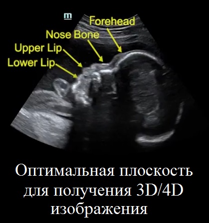
Во-первых, Вам нужно получить проекцию для измерения БПР (BPD). После этого следует повернуть датчик таким образом, чтобы получить сагиттальное сечение. Если Вы не в стандартном среднем сагиттальном сечении, нужно медленно скорректировать положение зонда до перехода к стандартной структуре с визуализацией лба, носа, верхней и нижней губы и т.д. После этого подготовительные работы в 2D режиме завершены.
Шаг второй: 3D сканирование
Нажмите клавишу 3D на панели управления, на экране появятся границы исследуемой области. Используйте клавишу [Set] и трекбол для регулировки размера исследуемой области (ROI), переместите её в нужное положение. Размер исследуемой области должен быть целесообразным — не маленьким и не слишком большим.
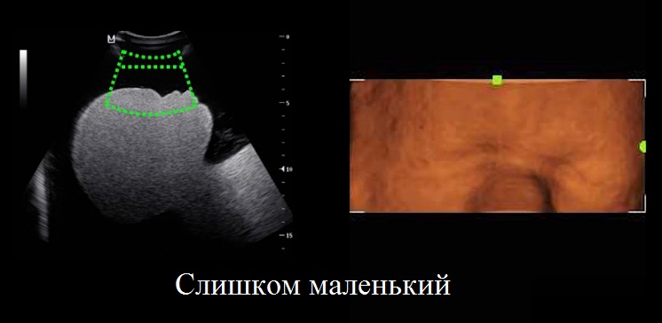
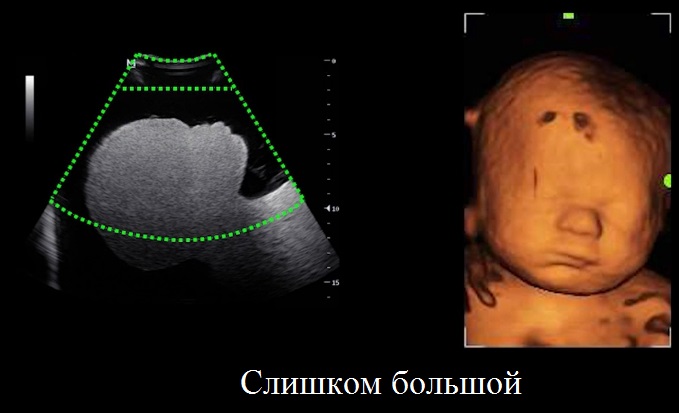
Переместите исследуемую область так, чтобы она вмещала всю головку плода. Неправильно выбранный исследуемый объём не позволит получить хорошее и полное 3D-изображение. Используйте клавишу [Set], чтобы активировать Огибающую VOI (Огибающая области интереса), затем трекболом сдвиньте огибающую как можно ближе к поверхности лица плода. Нажмите клавишу Обновить [Update] на панели управления, чтобы приступить к получению 3D-изображения. Затем зафиксируйте положение датчика.
Шаг третий: 4D сканирование
Нажмите клавишу 4D на панели управления, на экране появятся границы исследуемой области, так же, как в режиме статического 3D. Перемещая трекбол и нажимая клавишу [Set], последовательно настройте расположение, размер, а также кривую исследуемого объёма.
Нажмите клавишу Обновить [Update] на панели управления, чтобы приступить к получению 4D изображения. Нажмите кнопку Стоп-кадр [Freeze] для завершения получения 4D-изображения.
Шаг четвёртый: обработка 3D/4D данных
После получения 3D/4D изображения Вы можете редактировать изображение, чтобы улучшить его. Поверните рукоятку для изменения порогового значения. Слишком высокое значение приведёт к потере деталей, слишком низкое — к увеличению шума.
iLive — это революционный способ получения изображения плода с реалистичными оттенками кожи. Нажмите клавишу [iLive] на сенсорном экране, чтобы войти в режим iLive. Меняйте положение источника света и перемещайте свет при помощи трекбола для получения различных эффектов.
Нажмите клавишу [Single] для перехода в однооконный режим из многооконного. Нажмите клавишу [Dual] для перехода в двухоконный режим. Нажмите клавишу [Quad] для перехода в режим четырёхоконного изображения.
В режиме просмотра 3D нажмите кнопку [Сохранить] на панели управления для сохранения текущего изображения. В режиме просмотра 4D нажмите назначаемую пользователем клавишу сохранения (Сохр.клип (ретроспект.) на диске) в системе управления сведениями о пациентах.
Примеры объёмных УЗ изображений, полученных клиентами ТИАРА-МЕДИКАЛ
.jpeg)
.jpeg)
.jpeg)
.jpeg)
.jpeg)
.jpeg)
.jpeg)
.jpeg)
.jpeg)
Определение пола плода
.jpeg)
.jpeg)
![]()
Официальный представитель по продаже медицинского оборудования «Shenzhen Mindray Bio-Medical Electronics Co., Ltd» на территории РФ.
Ваш Регион
Москва
8(800)551-70-03
Whatsapp
Telegram
Пн-Чт: 09:30-18:00
Пт: 09:30-17:00