- Manuals
- Brands
- Toyota Manuals
- Automobile
- PRIUS 50 2020 Series
- Owner’s manual
-
Contents
-
Table of Contents
-
Troubleshooting
-
Bookmarks
Quick Links
Related Manuals for Toyota PRIUS 50 2020 Series
Summary of Contents for Toyota PRIUS 50 2020 Series
-
Page 3
Pictorial index Search by illustration For safety Make sure to read through them and security Instrument How to read the gauges and meters, the variety of cluster warning lights and indicators, etc. Operation of Opening and closing the doors and windows, each component adjustment before driving, etc. -
Page 4: Table Of Contents
TABLE OF CONTENTS For your information …….6 Instrument cluster Reading this manual…..12 How to search ……13 Pictorial index …….14 Instrument cluster Combination meter….78 For safety and security Warning lights and indicators……87 Main display ……93 1-1. For safe use Multi-information display …
-
Page 5
……..237 Inside rear view mirror ..179 4-5. Using the driving support systems Outside rear view mirrors ……181 Toyota Safety Sense..242 3-5. Opening and closing the PCS (Pre-Collision windows and moon roof System)……248 Power windows….183 LTA (Lane Tracing Assist) …… -
Page 6
TABLE OF CONTENTS Interior features Maintenance and care 5-1. Using the air conditioning 6-1. Maintenance and care system and defogger Cleaning and protecting Automatic air conditioning the vehicle exterior..366 system ……328 Cleaning and protecting the vehicle interior… 371 Seat heaters ……338 5-2. -
Page 7
For vehicles with navigation or multimedia system, refer to the “Nav- igation and Multimedia System Owner’s Manual” for information regarding the equipment listed below. • Navigation system • Hands-free system • Audio/visual system (for cellular phone) • Toyota parking assist monitor… -
Page 8: For Your Information
Accessories, spare parts and modification of your Toyota A wide variety of non-genuine spare parts and accessories for Toyota vehi- cles are currently available in the market. Using these spare parts and acces-…
-
Page 9
SRS airbag system ● Seat belt pretensioner system Be sure to check with your Toyota dealer for precautionary measures or spe- cial instructions regarding installation of an RF-transmitter system. Further information regarding frequency bands, power levels, antenna posi- tions and installation provisions for the installation of RF-transmitters, is avail- able on request at your Toyota dealer. -
Page 10
● Data usage Toyota may use the data recorded in this computer to diagnose malfunc- tions, conduct research and development, and improve quality. Toyota will not disclose the recorded data to a third party except: •… -
Page 11
EDR. ● Disclosure of the EDR data Toyota will not disclose the data recorded in an EDR to a third party except when: • An agreement from the vehicle’s owner (or the lessee for a leased vehi- cle) is obtained •… -
Page 12
Be sure to have the systems of the SRS airbag and seat belt pretensioner removed and disposed of by a qualified service shop or by your Toyota dealer before you scrap your vehicle. -
Page 14: Reading This Manual
Reading this manual WARNING: Explains something that, if not obeyed, could cause death or serious injury to people. NOTICE: Explains something that, if not obeyed, could cause damage to or a malfunction in the vehicle or its equipment. 1 2 3 Indicates operating or working procedures.
-
Page 15: How To Search
How to search ■ Searching by name • Alphabetical index ..P. 532 ■ Searching installation position • Pictorial index….P. 14 ■ Searching by symptom or sound • What to do if… (Troubleshooting) ..P. 528 ■ Searching by title •…
-
Page 16: Pictorial Index
Pictorial index Pictorial index ■ Exterior Side doors ……..P. 151 Locking/unlocking .
-
Page 17
Pictorial index Windshield wipers ……. . . P. 231 Precautions against winter season ….. P. 323 Precautions against car wash (vehicles with rain-sensing windshield wipers) . -
Page 18
Pictorial index ■ Instrument panel Power switch ……..P. 206 Starting the hybrid system/changing the modes . -
Page 19
Pictorial index Multi-information display ……P. 102 Display……… . . P. 102 Energy monitor . -
Page 20
Pictorial index ■ Switches EV drive mode switch ……P. 212 Driving mode select switch . -
Page 21
Pictorial index TRIP switch ……..P. 97 Audio remote control switches Meter control switches . -
Page 22
Pictorial index ■ Interior SRS airbags ……..P. 34 Floor mats . -
Page 23
Pictorial index Inside rear view mirror ……P. 179 Sun visors ……..P. 355 Vanity mirrors . -
Page 24
Pictorial index… -
Page 25: For Safety And Security
For safety and security 1-1. For safe use Before driving…….24 For safe driving ….26 Seat belts……28 SRS airbags……34 Exhaust gas precautions ..44 1-2. Child safety Riding with children….45 Child restraint systems ..46 1-3. Hybrid system Hybrid system features ..65 Hybrid system precautions ……69 1-4.
-
Page 26: 1-1. For Safe Use
1-1. For safe use Before driving Floor mat Use only floor mats designed specifically for vehicles of the same model and model year as your vehicle. Fix them securely in place onto the carpet. Insert the retaining hooks (clips) into the floor mat eyelets. Turn the upper knob of each retaining hook (clip) to secure the floor mats in place.
-
Page 27
When installing the driver’s floor mat ● Do not use floor mats designed for other models or different model year vehicles, even if they are Toyota Genuine floor mats. ● Only use floor mats designed for the driver’s seat. ●… -
Page 28: For Safe Driving
1-1. For safe use For safe driving For safe driving, adjust the seat and mirror to an appropriate position before driving. Correct driving posture Adjust the angle of the seat- back so that you are sitting straight up and so that you do not have to lean forward to steer.
-
Page 29
1-1. For safe use WARNING Observe the following precautions. Failure to do so may result in death or serious injury. ● Do not adjust the position of the driver’s seat while driving. Doing so could cause the driver to lose control of the vehicle. ●… -
Page 30: Seat Belts
1-1. For safe use Seat belts Make sure that all occupants are wearing their seat belts before driving the vehicle. Correct use of the seat belts ● Extend the shoulder belt so that it comes fully over the shoulder, but does not come into contact with the neck or slide off the shoulder.
-
Page 31
1-1. For safe use Adjusting the seat belt shoulder anchor height (front seats) Push the seat belt shoulder Release button anchor down while pressing the release button. Push the seat belt shoulder anchor up while pressing the release button. Move the height adjuster up and down as needed until you hear a click. -
Page 32
If the vehicle is involved in multiple collisions, the pretensioner will activate for the first collision, but will not activate for the second or subsequent collisions. ■ Seat belt regulations If seat belt regulations exist in the country where you reside, please contact your Toyota dealer for seat belt replacement or installation. -
Page 33
Each seat belt should be used by one person only. Do not use a seat belt for more than one person at once, including children. ● Toyota recommends that children be seated in the rear seat and always use a seat belt and/or an appropriate child restraint system. ●… -
Page 34
Seat belt pretensioners If the pretensioner has activated, the SRS warning light will come on. In that case, the seat belt cannot be used again and must be replaced at your Toyota dealer. ■ Adjustable shoulder anchor Always make sure the shoulder belt is positioned across the center of your shoulder. -
Page 35
● Ensure that the belt and plate are locked and the belt is not twisted. If the seat belt does not function correctly, immediately contact your Toyota dealer. ● Replace the seat assembly, including the belts, if your vehicle has been involved in a serious accident, even if there is no obvious damage. -
Page 36: Srs Airbags
1-1. For safe use SRS airbags The SRS airbags inflate when the vehicle is subjected to certain types of severe impacts that may cause significant injury to the occupants. They work together with the seat belts to help reduce the risk of death or serious injury. ◆…
-
Page 37
1-1. For safe use SRS airbag system components Seat belt pretensioners and Side impact sensors (front) force limiters Front passenger airbag Curtain shield airbags SRS warning light Side impact sensors (rear) Front impact sensors Side airbags Airbag sensor assembly Side impact sensors (front… -
Page 38
An infant or child who is too small to use a seat belt should be properly secured using a child restraint sys- tem. Toyota strongly recommends that all infants and children be placed in the rear seats of the vehicle and properly restrained. The rear seats are… -
Page 39
1-1. For safe use WARNING ■ SRS airbag precautions ● Do not sit on the edge of the seat or lean against the dashboard. ● Do not allow a child to stand in front of the SRS front passenger airbag unit or sit on the knees of a front passenger. -
Page 40
Wash off any residue as soon as possible to prevent skin irritation. ● If the areas where the SRS airbags are stored, such as the steering wheel pad and front and rear pillar garnishes, are damaged or cracked, have them replaced by your Toyota dealer. -
Page 41
Modification and disposal of SRS airbag system components Do not dispose of your vehicle or perform any of the following modifications without consulting your Toyota dealer. The SRS airbags may malfunction or deploy (inflate) accidentally, causing death or serious injury. -
Page 42
1-1. For safe use ■ If the SRS airbags deploy (inflate) ● Slight abrasions, burns, bruising etc., may be sustained from SRS airbags, due to the extremely high speed deployment (inflation) by hot gases. ● A loud noise and white powder will be emitted. ●… -
Page 43
1-1. For safe use ■ Conditions under which the SRS airbags may deploy (inflate), other than a collision The SRS front airbags and SRS curtain shield airbags may also deploy if a serious impact occurs to the underside of your vehicle. Some examples are shown in the illustration. -
Page 44
1-1. For safe use ■ Types of collisions that may not deploy the SRS airbags (SRS side and curtain shield airbags) The SRS side and curtain shield airbags may not activate if the vehicle is subjected to a collision from the side at certain angles, or a collision to the side of the vehicle body other than the passenger compartment. -
Page 45
1-1. For safe use ■ When to contact your Toyota dealer In the following cases, the vehicle will require inspection and/or repair. Con- tact your Toyota dealer as soon as possible. ● Any of the SRS airbags have been inflated. ●… -
Page 46: Exhaust Gas Precautions
Exhaust pipe The exhaust system needs to be checked periodically. If there is a hole or crack caused by corrosion, damage to a joint or abnormal exhaust noise, be sure to have the vehicle inspected and repaired by your Toyota dealer.
-
Page 47: Child Safety
1-2. Child safety Riding with children Observe the following precautions when children are in the vehi- cle. Use a child restraint system appropriate for the child, until the child becomes large enough to properly wear the vehicle’s seat belt. ● It is recommended that children sit in the rear seats to avoid acci- dental contact with the shift lever, wiper switch etc.
-
Page 48: Child Restraint Systems
1-2. Child safety Child restraint systems Before installing a child restraint system in the vehicle, there are precautions that need to be observed, different types of child restraint systems, as well as installation methods, etc., written in this manual. ● Use a child restraint system when riding with a small child that cannot properly use a seat belt.
-
Page 49
● Toyota strongly urges the use of a proper child restraint system that con- forms to the weight and size of the child, installed on the rear seat. Accord- ing to accident statistics, the child is safer when properly restrained in the rear seat than in the front seat. -
Page 50
1-2. Child safety When using a child restraint system ■ When installing a child restraint system to a front passenger seat For the safety of a child, install a child restraint system to a rear seat. When installing a child restraint system to the front passenger seat is unavoidable, adjust the seat as follows and install the child restraint system. -
Page 51
1-2. Child safety WARNING ■ When using a child restraint system Observe the following precautions. Failure to do so may result in death or serious injury. ● Extreme Hazard! Do not use a rearward facing child restraint on a seat protected by an airbag in front of it! This is because the force of the rapid inflation of the front passenger airbag can cause… -
Page 52
1-2. Child safety WARNING ■ When using a child restraint system ● Only put a forward-facing child restraint system on the front seat when unavoid- able. When installing a forward-facing child restraint on the front passenger seat, move the seat as far back as pos- sible. -
Page 53
1-2. Child safety Child restraint system compatibility for each seating position ■ Child restraint system compatibility for each seating position Compatibility of each seating position with child restraint systems (P. 53) displays the type of child restraint systems that can be used and possible seating positions for installation using symbols. -
Page 54
1-2. Child safety : UN(ECE) R44 and UN(ECE) R129 are U.N. regulations for child restraint systems. : The child restraint systems mentioned in the table may not be avail- able outside of the EU area. : The displayed mark may differ depending on the product. Checking the category of the child restraint system. -
Page 55
1-2. Child safety ■ Compatibility of each seating position with child restraint sys- tems 1, 2, 3 Suitable for “universal” category child restraint system fixed with the seat belt. Suitable for i-Size and ISOFIX child restraint system. Includes a top tether anchorage point. Never use a rear-facing child restraint system on the front passen- ger seat. -
Page 56
1-2. Child safety : Move the front seat fully rearward. If the passenger seat height can be adjusted, move it to the upper most position. : Adjust the seatback angle to the most upright position. When installing a forward-facing child seat, if there is a gap between the child seat and the seatback, adjust the seatback angle until good contact is achieved. -
Page 57
1-2. Child safety ■ Detail information for child restraint systems installation Seating position Seat position number Forward Seating position suitable for universal belted (Yes/No) facing only i-Size seating position (Yes/No) Seating position suitable for lateral fix- ture (L1/L2/No) R1, R2X, R1, R2X, Suitable rearward facing fixture (R1/ R2, R3… -
Page 58
1-2. Child safety ISOFIX child restraint systems are divided into different “fixture”. The child restraint system can be used in the seating positions for “fixture” mentioned in the table above. For kind of “fixture” relation, confirm the following table. If your child restraint system has no kind of “fixture” (or if you can- not find information in the table below), please refer to the child restraint system “vehicle list”… -
Page 59
1-2. Child safety ● When installing a child restraint in the rear seats, adjust the front seat so that it does not interfere with the child or child restraint system. ● When installing a child seat with support base, if the child seat interferes with the seatback when latching it into the support base, adjust the seatback rearward until there is no interference. -
Page 60
1-2. Child safety Child restraint system installation method Confirm with the operation manual enclosed with the child restraint system about the installation of the child restraint system. Installation method Page Seat belt attach- P. 59 ment ISOFIX rigid anchor P. 61 attachment Child restraint anchor fitting… -
Page 61
1-2. Child safety Child restraint system fixed with a seat belt ■ Installing child restraint system using a seat belt Install the child restraint system in accordance to the operation manual enclosed with the child restraint system. If the child restraint system on hand is not within the “universal” cat- egory (or the necessary information is not in the table), refer to the “Vehicle List”… -
Page 62
You may need a locking clip to install the child restraint system. Follow the instructions provided by the manufacturer of the system. If your child restraint system does not provide a locking clip, you can purchase the following item from your Toyota dealer: Locking clip for child restraint system (Part No. 73119-22010) WARNING ■… -
Page 63
1-2. Child safety Child restraint system fixed with an ISOFIX rigid anchor ■ ISOFIX rigid anchors (ISOFIX child restraint system) Lower anchors are provided for the rear outboard seats. (But- tons displaying the location of the anchors are attached to the seats.) ■… -
Page 64
1-2. Child safety Check the positions of the exclusive fixing bars, and install the child restraint sys- tem to the seat. The bars are installed in the clearance between the seat cushion and seatback. After installing the child restraint system, rock it back and forth to ensure that it is installed securely. -
Page 65
1-2. Child safety Using a child restraint anchor fitting ■ Child restraint anchor fitting Anchor fittings are provided for each rear seat. Use anchor fittings when fixing the strap. ■ Fixing the strap to the anchor fitting Install the child restraint system in accordance to the operation manual enclosed with the child restraint system. -
Page 66
1-2. Child safety WARNING ■ When installing a child restraint system Observe the following precautions. Failure to do so may result in death or serious injury. ● Firmly attach the upper anchorage strap and make sure that the belt is not twisted. -
Page 67: Hybrid System
1-3. Hybrid system Hybrid system features Your vehicle is a hybrid vehicle. It has characteristics different from conventional vehicles. Be sure you are closely familiar with the characteristics of your vehicle, and operate it with care. The hybrid system combines the use of a gasoline engine and an electric motor (traction motor) according to driving condi- tions, improving fuel efficiency and reducing exhaust emis- sions.
-
Page 68
1-3. Hybrid system ◆ When stopped/during start off The gasoline engine stops when the vehicle is stopped. During start off, the electric motor (traction motor) drives the vehicle. At slow speeds or when traveling down a gentle slope, the engine is stopped and the electric motor (traction motor) is used. -
Page 69
30 minutes or 16 km (10 miles). If the hybrid battery (traction battery) becomes fully discharged and you are unable to start the hybrid system, contact your Toyota dealer. ■ Charging the 12-volt battery P. -
Page 70
Vibration may be felt when the gasoline engine starts or stops. ● Cooling fan sounds may be heard from the air intake vent. (P. 70) ■ Maintenance, repair, recycling, and disposal Contact your Toyota dealer regarding maintenance, repair, recycling and dis- posal. Do not dispose of the vehicle yourself. -
Page 71: Hybrid System Precautions
1-3. Hybrid system Hybrid system precautions Take care when handling the hybrid system, as it is a high volt- age system (about 600 V at maximum) as well as contains parts that become extremely hot when the hybrid system is operating. Obey the warning labels attached to the vehicle.
-
Page 72
If the emergency shut off system activates, your vehicle will not restart. To restart the hybrid system, contact your Toyota dealer. Hybrid warning message A message is automatically displayed when a malfunction occurs in the hybrid system or an improper operation is attempted. -
Page 73
If a warning light comes on, a warning message is displayed, or the 12-volt battery is disconnected The hybrid system may not start. In this case, try to start the system again. If the “READY” indicator does not come on, contact your Toyota dealer. ■ Running out of fuel… -
Page 74
1-3. Hybrid system WARNING ■ High voltage precautions This vehicle has high voltage DC and AC systems as well as a 12-volt sys- tem. DC and AC high voltage is very dangerous and can cause severe burns and electric shock that may result in death or serious injury. ●… -
Page 75
Toyota dealer or a qualified service shop. If the hybrid battery is not dis- posed of properly, it may cause electric shock that can result in death or… -
Page 76
Do not carry large amounts of water such as water cooler bottles in the vehicle. If water spills onto the hybrid battery (traction battery), the battery may be damaged. Have the vehicle inspected by your Toyota dealer. ● There is a filter installed to the air intake vent. When the filter remains noticeably dirty even after cleaning the air intake vent, filter cleaning or replacement is recommended. -
Page 77: Theft Deterrent System
1-4. Theft deterrent system Immobilizer system The vehicle’s keys have built-in transponder chips that prevent the hybrid system from starting if a key has not been previously registered in the vehicle’s on-board computer. Never leave the keys inside the vehicle when you leave the vehi- cle.
-
Page 78
1-4. Theft deterrent system… -
Page 79: Instrument Cluster
Instrument cluster Instrument cluster Combination meter ….78 Warning lights and indicators ……87 Main display……93 Multi-information display ..102 Head-up display….132 Energy monitor/ consumption screen ..140…
-
Page 80: Combination Meter
2. Instrument cluster Combination meter The large meter uses 2 liquid crystal displays to display informa- tion such as the vehicle condition, driving status and fuel con- sumption. Combination meter layout Main display (P. 93) The main display shows basic information related to driving, such as the vehicle speed and remaining fuel amount.
-
Page 81
2. Instrument cluster Operations related to the combination meter The meter control switches equipped on the steering wheel can be used to switch the screen display and change settings related to func- tions displayed on the screen. Each time button pressed, the mileage display switches among odometer, trip meters, etc., and the fuel con-… -
Page 82
2. Instrument cluster Instrument cluster light control To adjust the brightness of the instrument cluster light, perform opera- tions on the screen of the multi-information display. (P. 126) The instrument cluster brightness levels that can be selected differ depending on whether the tail lights are on and surrounding brightness lev- els. -
Page 83
2. Instrument cluster Information automatically displayed Some information will be displayed automatically according to power switch operation, vehicle condition, etc. ■ When starting the hybrid system When the hybrid system starts, an opening animation is dis- played on the 2 displays. After the animation ends, the screens switch to the normal screen. -
Page 84
2. Instrument cluster ■ When there is information to be notified about the vehicle When a shift position is mistakenly selected or a problem occurs in a vehicle system, a warning message (or image) is displayed on the multi-information display. When a warning message is displayed, follow the instructions displayed on the display. -
Page 85
2. Instrument cluster Clock adjustment To adjust the time, perform operations on the screen (P. 119) of the multi-information display. ■ Adjusting the time Press of the meter control switches on the steering wheel and select Press of the meter control switches and select Press to display the cursor. -
Page 86
2. Instrument cluster ■ Resetting the minutes display Press of the meter control switches on the steering wheel and select Press of the meter control switches and select Press The minutes display switches to “00”. : e.g. 1:00 to 1:29 1:00 1:30 to 1:59 … -
Page 87
2. Instrument cluster ■ The meters and display illuminate when The power switch is in ON mode. ■ Adjusting the instrument cluster brightness (P. 80) ● The brightness levels that can be selected differ depending on whether the tail lights are on and surrounding brightness levels, as shown in the table below. -
Page 88
2. Instrument cluster ■ Liquid crystal display Small spots or light spots may appear on the display. This phenomenon is characteristic of liquid crystal displays, and there is no problem continuing to use the display. ■ Pop-up display Some functions, such as the driving mode select switch and air conditioning system, are operation-linked and display pop-up screens on the multi-infor- mation display. -
Page 89: Warning Lights And Indicators
2. Instrument cluster Warning lights and indicators The warning lights and indicators inform the driver of the status of the vehicle’s various systems. For the purpose of explanation, the following illustration dis- plays all indicators and warning lights illuminated.
-
Page 90
2. Instrument cluster Warning lights Warning lights inform the driver of malfunctions in any of the vehicle’s systems. Warning lights Pages Brake system warning light (Red) P. 442 Brake system warning light (Yellow) P. 442 Charging system warning light P. 442 Low engine oil pressure warning light P. -
Page 91
There may be a malfunction in a system if a light does not come on, or turn off. Have the vehicle inspected by your Toyota dealer. : The light flashes or illuminates to indicate a malfunction. -
Page 92
There may be a malfunction in a system if a light does not come on, or turn off. Have the vehicle inspected by your Toyota dealer. : The light flashes to indicate that the system is operating. -
Page 93
2. Instrument cluster Indicators and symbols displayed on the display ■ Main display and multi-information display Indicators Pages EV drive mode indicator P. 212 “ECO MODE” indicator P. 299 “PWR MODE” indicator P. 299 EV Indicator P. 108 : The displayed indicator changes according to the current driving mode. ■… -
Page 94
Have the vehicle inspected by your Toyota dealer immediately if this occurs. -
Page 95: Main Display
2. Instrument cluster Main display The main display shows basic information, such as the vehicle speed and remaining fuel amount. Also, the displayed informa- tion can be switched according to user preference. Display contents (vehicles without RSA [Road Sign Assist]) Simple screen Split screen : Refer to P.
-
Page 96
2. Instrument cluster Speedometer Displays the vehicle speed Outside temperature Displays the outside temperature within the range of -40°C (-40°F) to 50°C (122°F). The temperature display flashes for approximately 10 seconds when the outside temperature drops to approximately 3°C (37°F) or less, and then stops flashing. -
Page 97
2. Instrument cluster Display contents (vehicles with RSA [Road Sign Assist]) -
Page 98
2. Instrument cluster Speedometer Displays the vehicle speed Fuel gauge Displays the quantity of fuel remaining in the tank Outside temperature Displays the outside temperature within the range of -40°C (-40°F) to 50°C (122°F). The temperature display flashes for approximately 10 seconds when the outside temperature drops to approximately 3°C (37°F) or less, and then stops flashing. -
Page 99
2. Instrument cluster Switching the average fuel consumption display and mileage display Each time is pressed, the fuel consumption display and mileage display change in the following order from 1 to 6. Average fuel consumption dis- play Mileage display After 1 to 6 are displayed, the dis- plays return to 1. -
Page 100
2. Instrument cluster Average fuel consumption display Mileage display Average fuel consumption since last reset ODO (Odometer) Average fuel consumption since Total mileage last reset TRIP A average fuel consumption TRIP A (Trip meter A) Average fuel consumption since Mileage since last reset TRIP A was reset TRIP B average fuel consumption TRIP B (Trip meter B) -
Page 101
2. Instrument cluster Switching the display mode (vehicles without RSA [Road Sign Assist]) Simple screen or split screen can be selected for the main display. When split screen is selected, a variety of information can be displayed on a sub-screen in addition to the contents of the simple screen. Select the “Meter Customize”… -
Page 102
2. Instrument cluster Switching contents displayed on the sub-screen Vehicles without RSA (Road Sign Assist) When split screen is selected for the main display, display contents on the sub-screen can be selected. Vehicles with RSA (Road Sign Assist) When RSA is off, display contents on the sub-screen can be selected. -
Page 103
• When the outside temperature has changed suddenly (at the entrance/ exit of a garage, tunnel, etc.) ● When “-” or “E” is displayed, the system may be malfunctioning. Take your vehicle to your Toyota dealer. ■ Distance to empty ●… -
Page 104: Multi-Information Display
2. Instrument cluster Multi-information display A variety of information related to the vehicle can be displayed, including the operation status of each system and data related to Eco driving, and the settings of each system can be changed according to user preference. Display contents Information related to each icon on the upper portion of the multi-…
-
Page 105
2. Instrument cluster Menu icons Contents Pages Drive information The energy monitor that shows the operation P. 104 status of the hybrid system, or other informa- tion such as fuel consumption is displayed. Clock setting display P. 119 The clock settings can be changed. Navigation system-linked display The information related to the navigation sys- P. -
Page 106
2. Instrument cluster Basic Operations Press of the meter control switches and select the icon of the desired item. The selected icon is highlighted and the display switches to the information screen. When split screen display is selected for the main display or RSA (Road Sign Assist) is off, the sub-screen of the main display can also be selected. -
Page 107
2. Instrument cluster ◆ Energy monitor The energy monitor can be used to check the vehicle drive status, hybrid system operation status and energy regeneration status. When energy is flowing, an arrow appears and a bright point of light moves to show the direction of the flow of energy. When energy is not flowing, the bright point of light is not displayed. -
Page 108
2. Instrument cluster ■ Hybrid battery (traction battery) status ● The display changes in 8 levels according to the remaining charge amount of the hybrid battery (traction battery). High ● The hybrid battery (traction battery) status is also displayed on the following screen, but the contents of the display are the same. -
Page 109
2. Instrument cluster ◆ Hybrid System Indicator The display changes according to accelerator pedal operation and displays the current driving status and energy regeneration status. The Hybrid System Indicator can be displayed on the sub-screen of the main display (P. 100) and the head-up display (if equipped) (P. 132). -
Page 110
2. Instrument cluster 2, 3 EV indicator The EV indicator comes on when the vehicle is driven using only the electric motor (traction motor) or the gasoline engine is stopped. Hybrid battery (traction battery) status P. 106 Eco score P. 109 ●… -
Page 111
2. Instrument cluster ■ Eco score The driving status for the following 3 situations are evaluated in 5 levels: Smooth start-off acceleration (“Eco-Start”), driving without sudden acceleration (“Eco-Cruise”) and smooth stopping (“Eco- Stop”). Each time the vehicle is stopped, a score result is displayed out of a perfect score of 100 points. -
Page 112
2. Instrument cluster ■ When operation of each function stops ● The Hybrid System Indicator stops operating in the following situations. • The “READY” indicator is not illuminated. • The shift position is not D or B. ● The Eco score and “ECO Accelerator Guidance” stop operating in the fol- lowing situations. -
Page 113
2. Instrument cluster ◆ “Fuel Consumption Record” The transitions of the average fuel consumption after the hybrid system starts can be checked in such a unit as every 5 minutes or every 1 km (0.6 mile) of driving. Also, it is possible to check the average fuel consumption history for each month by switching to the “Monthly”… -
Page 114
2. Instrument cluster ■ Types of “fuel Consumption Record” Tab display Recorded contents Recorded range Average fuel consumption “5 min” The past 30 minutes of every 5 minutes Average fuel consumption The last 15 km (9.3 miles) “1 km” of every 1 km (0.6 mile) driven driven Average fuel consumption… -
Page 115
2. Instrument cluster ◆ “Drive Monitor” Displays information such as the driving time and average vehicle speed, which are linked with the current mileage display. (P. 97) Current contents of the dis- play Displayed information shows which driving record the cur- rently displayed contents are based on. -
Page 116
2. Instrument cluster ◆ “Eco Savings” “Gasoline Price” and “COMP. Consumption” information is regis- tered in the “Meter Customize” settings (P. 128), making it possi- ble to display 2 types of information related to gasoline fuel consumption. “SAVINGS” If information about the vehicle used to compare fuel consumption (“COMP. -
Page 117
2. Instrument cluster ■ How to read the display “SAVINGS” display “FUEL COST” display Trip meter distance traveled Estimate of fuel consumption saved for displayed distance trav- eled Estimate of fuel expenses necessary to drive currently displayed distance Estimate of fuel expenses to drive currently displayed distance (your vehicle) Estimate of fuel expenses to drive currently displayed distance (comparison vehicle) -
Page 118
2. Instrument cluster ■ Checking monthly record The display can be switched to “TRIP” or “Monthly” by pressing with the tab display selected, and then pressing of the meter control switches. Using the “Monthly” display, the monthly records for “SAVINGS” and “FUEL COST”… -
Page 119
2. Instrument cluster ◆ “Eco-Diary” The distance traveled and average fuel consumption history can be displayed in a table according to day (“Daily”) or month (“Monthly”) units. ■ How to read the display “Daily” display “Monthly” display Record of the day/month Date/month of stored information Total distance traveled for the day/month Average fuel consumption of the day/month… -
Page 120
2. Instrument cluster ■ Checking history When each screen is selected, past records from the following ranges can be displayed by pressing of the meter con- trol switches. Displayed screen Displayed information Stored information Up to 32 reports “Daily” (8 screens) 4 reports Up to 12 reports “Monthly”… -
Page 121
2. Instrument cluster Clock setting display clock settings changed. Item Setting result Adjusts the clock. (P. 83) Sets the minutes to “00”. (P. 84) -
Page 122
2. Instrument cluster Navigation system-linked display (if equipped) Displays a compass linked with the navigation system. Also, when the navigation system is perform- ing intersection guidance during destination guidance, the inter- section guidance is also displayed on the multi-information display. The illustration is only an example and may differ from the actual screen. -
Page 123
2. Instrument cluster Air conditioning system settings screen The condition of the air conditioning system settings can be checked on the screen and the air conditioning system settings can be changed using the meter control switches. On the air conditioning settings screen, press of the meter con- trol switches to switch the contents of the display. -
Page 124
2. Instrument cluster Item Settings Eco score P. 123 (A/C score) Temperature Changes according to operation of the meter control setting switches Outside air and recirculated air (Outside air mode) (Recirculated air mode) modes Fan speed 1 to 7 “CLIMATE “NORMAL”… -
Page 125
2. Instrument cluster ■ Eco score (A/C score) The current air conditioning system usage status is evaluated in 5 levels to determine whether it is Eco-friendly. The evaluation changes according to the air conditioning system usage status. When the power switch is turned off, the current total driving score and advice related to using the air conditioning… -
Page 126
2. Instrument cluster ■ Eco score (A/C score) ● The setting status of the following air conditioning system functions are reflected in the score. • Temperature setting • Fan speed setting • Outside air and recirculated air modes • “A/C” button •… -
Page 127
2. Instrument cluster Driving assist system information The operation status of driving support system such as the LTA (Lane Tracing Assist) equipped) and dynamic radar cruise control with full-speed range (if equipped) and warning information are displayed. For details regarding the driving support functions, refer to the page for the corresponding function. -
Page 128
2. Instrument cluster Settings display The operation contents of the driving support systems and settings related to the combination meter display can be changed. Driving support systems such as the PCS (Pre-Collision System) (if equipped) and Blind Spot Monitor (if equipped) is turned on and off by sim- ply pressing . -
Page 129
2. Instrument cluster ■ Settings table Item Settings Setting result “On” Turns the LTA (Lane Tracing Assist) lane centering function on and off. (P. 259) “Off” “On” Turns the LTA (Lane Tracing Assist) steer- ing assist function on and off. (P. 259) “Off”… -
Page 130
2. Instrument cluster Item Settings Setting result “Vehicle Settings” settings: P. 518 : If equipped ■ “Meter Customize” settings ( Item Settings Setting result “Simple” “Simple/Split Switches the display mode of Screen” the main display. (P. 99) “Split” “Yes” “Screen Turns the multi-information dis- OFF”… -
Page 131
2. Instrument cluster Item Settings Setting result “Gasoline Price” “Eco Savings” Registers data used to calcu- (P. 114) late and record “Eco Savings”. “COMP. Consumption” Deletes data of “Fuel Con- “Yes” “Monthly Fuel sumption Record (Monthly)”. Consumption” “No” (P. 111) “Yes”… -
Page 132
2. Instrument cluster ■ Setting items ● “Meter Customize” and “Vehicle Settings” setting items are not selectable during driving and cannot be operated. Also, the settings screen is temporarily canceled in the following situations. • A warning message is displayed. •… -
Page 133
2. Instrument cluster WARNING ■ Cautions while setting up the display As the hybrid system needs to be operating during setting up the display, ensure that the vehicle is parked in a place with adequate ventilation. In a closed area such as a garage, exhaust gases including harmful carbon monoxide (CO) may collect and enter the vehicle. -
Page 134: Head-Up Display
2. Instrument cluster Head-up display The head-up display can display the current vehicle speed and Hybrid System Indicator in front of the driver. Also, it can display various types of information to assist the driver. Operation switches and display contents Meter control switches These switches are used when adjusting the display position and bright- ness of the head-up display.
-
Page 135
2. Instrument cluster Insert display P. 136 ( This display inserts information from each driving support system accord- ing to driving conditions. Route guidance display (vehicles with navigation system) (P. 137) This display is automatically shown when the navigation system is per- forming route guidance. -
Page 136
2. Instrument cluster ■ When the head-up display is on Display items can be switched by pressing the “HUD” switch. Vehicle speed display and cruise control display Vehicle speed display and Hybrid System Indicator Refer to P. 107 for details of the Hybrid System Indicator. -
Page 137
2. Instrument cluster Display position and brightness adjustment In order to improve the visibility of the head-up display, the display position and brightness can be adjusted. Displaying the adjustment screen on the multi-information display. When the head-up display is on: Select on the screen of the multi-information dis-… -
Page 138
2. Instrument cluster Insert display ■ Insert displays of the driving support systems Insert displays are linked with the operation of the following sys- tems and used to show some of the information shown on the multi- information display on the head-up display. System Displayed information PCS (Pre-Collision System) (P. -
Page 139
2. Instrument cluster Route guidance display (vehicles with navigation system) When the navigation system route guidance is set, convenient route guidance is displayed. When approaching an intersec- tion, the shape of the intersection and the remaining distance to the intersection are displayed. -
Page 140
2. Instrument cluster ■ Enabling/disabling of the head-up display When the head-up display is turned off with the “HUD” switch, it is not dis- played until the “HUD” switch is used to turn the head-up display on again. (Operation of the head-up display is not linked with the power switch.) ■… -
Page 141
2. Instrument cluster WARNING ■ Before using the head-up display ● Check that the position and brightness of the head-up display image does not interfere with safe driving. Incorrect adjustment of the image’s position or brightness may obstruct the driver’s view and lead to an accident, resulting in death or serious injury. -
Page 142: Energy Monitor/Consumption Screen
2. Instrument cluster Energy monitor/consumption screen You can view the status of your vehicle on the multi-information display and the audio system screen : For navigation system or multimedia system ◆ Multi-information display P. 102 ◆ Audio system screen Display the energy monitor, trip information or history screen. …
-
Page 143
2. Instrument cluster Energy monitor If a screen other than “Energy” is displayed, select “Energy”. Audio system screen When the vehicle is powered by electric motor (traction motor) When the vehicle is powered by both the gasoline engine and electric motor (traction motor) -
Page 144
2. Instrument cluster Audio system screen When the vehicle is charging the hybrid battery (traction bat- tery) When there is no energy flow Full Hybrid battery (traction battery) status These images are examples only, and may vary slightly from actual conditions. -
Page 145
2. Instrument cluster Fuel consumption ■ Trip information If a screen other than “Trip information” is displayed select “Trip information”. Fuel consumption in the past 15 minutes Regenerated energy in the past 15 minutes symbol indicates 30 Wh. Up to 5 symbols are shown. Current fuel consumption Resetting the consumption data… -
Page 146
2. Instrument cluster ■ History If a screen other than “History” is displayed, select “History”. Best recorded fuel consump- tion Latest fuel consumption Previous fuel consumption record • Without navigation function: Displays the daily average fuel consumption. (Instead of the date, “Trip 1”… -
Page 147: Operation Of Each Component
Operation of each component 3-1. Key information Keys……..146 3-2. Opening, closing and locking the doors Side doors……151 Back door……156 Smart entry & start system ……161 3-3. Adjusting the seats Front seats……168 Rear seats ……170 Head restraints ….173 3-4. Adjusting the steering wheel and mirrors Steering wheel ….177 Inside rear view mirror ..179…
-
Page 148: 3-1. Key Information
Closes the side windows and moon roof (if equipped) (P. 151) Unlocks all the doors (P. 151) Opens the side windows and moon roof (if equipped) (P. 151) Sounds the alarm (P. 147) : These settings must be customized at your Toyota dealer.
-
Page 149
■ If you lose your mechanical keys New genuine mechanical keys can be made by your Toyota dealer using another mechanical key and the key number stamped on your key number plate. Keep the plate in a safe place such as your wallet, not in the vehicle. -
Page 150
You can replace the battery by yourself (P. 417). However, as there is a danger that the electronic key may be damaged, it is recommended that replacement is carried out by your Toyota dealer. ● To avoid serious deterioration, do not leave the electronic key within 1 m (3 ft.) of the following electrical appliances that produce a magnetic field:… -
Page 151
If this message is displayed but you have not had a new electronic key regis- tered, ask your Toyota dealer to check if an unknown electronic key (other than those in your possession) has been registered. -
Page 152
Toyota dealer. ■ When an electronic key is lost If the electronic key remains lost, the risk of vehicle theft increases signifi- cantly. Visit your Toyota dealer immediately with all remaining electronic keys that were provided with your vehicle. -
Page 153: Side Doors
Press and hold to close the side windows and moon roof (if equipped). Unlocks all the doors Press and hold to open the side windows and moon roof (if equipped). : These settings must be customized at your Toyota dealer.
-
Page 154
3-2. Opening, closing and locking the doors ■ Operation signals Doors: A buzzer sounds and the emergency flashers flash to indicate that the doors have been locked/unlocked. (Locked: Once; Unlocked: Twice) Side windows and moon roof (if equipped): A buzzer sounds to indicate that the side windows and moon roof are operat- ing. -
Page 155
3-2. Opening, closing and locking the doors Locking and unlocking the doors from the inside ◆ Door lock switches Locks all the doors Unlocks all the doors ◆ Inside lock buttons Locks the door Unlocks the door The driver’s door can be opened by pulling the inside handle even if the lock button is in the lock position. -
Page 156
3-2. Opening, closing and locking the doors Rear door child-protector lock The door cannot be opened from inside the vehicle when the lock is set. Unlock Lock These locks can be set to prevent children from opening the rear doors. Push down on each rear door switch to lock both rear doors. -
Page 157
3-2. Opening, closing and locking the doors WARNING ■ To prevent an accident Observe the following precautions while driving the vehicle. Failure to do so may result in a door opening and an occupant could be thrown out of the vehicle, resulting in death or serious injury. ●… -
Page 158: Back Door
3-2. Opening, closing and locking the doors Back door The back door can be unlocked/locked and opened/closed by the following procedures. ◆ Smart entry & start system Carry the electronic key to enable this function. Locks all the doors Check that the door is securely locked.
-
Page 159
3-2. Opening, closing and locking the doors When closing the back door Lower the back door using the back door handle, and make sure to push the back door down from the outside to close it. Be careful not to pull the back door sideways when closing the back door with the handle. -
Page 160
3-2. Opening, closing and locking the doors WARNING Observe the following precautions. Failure to do so may result in death or serious injury. ■ Before driving ● Make sure that the back door is fully closed. If the back door is not fully closed, it may open unexpectedly while driving and hit near-by objects or luggage in the luggage compartment may be thrown out, causing an acci- dent. -
Page 161
If a bicycle carrier or similar heavy object is attached to the back door, it may suddenly shut again after being opened, causing someone’s hands, head or neck to be caught and injured. When installing an accessory part to the back door, using a genuine Toyota part is recommended. -
Page 162
Do not touch the damper stay rod with gloves or other fabric items. ● Do not attach any accessories other than genuine Toyota parts to the back door. ● Do not place your hand on the damper stay or apply lateral forces to it. -
Page 163: Smart Entry & Start System
3-2. Opening, closing and locking the doors Smart entry & start system The following operations can be performed simply by carrying the electronic key on your person, for example in your pocket. The driver should always carry the electronic key. ●…
-
Page 164
3-2. Opening, closing and locking the doors ■ Effective range (areas within which the electronic key is detected) When locking or unlocking the doors The system can be operated when the electronic key is within about 0.7 m (2.3 ft.) of driver’s door handle, front passenger’s door handle and back door opener switch. -
Page 165
When “Smart Entry & Start System Malfunction See Owner’s Manual” is displayed on the multi-information display The system may be malfunctioning. Have the vehicle inspected by your Toyota dealer immediately. ■ Battery-saving function The battery-saving function will be activated in order to prevent the electronic key battery and the 12-volt battery from being discharged while the vehicle is not in operation for a long time. -
Page 166
3-2. Opening, closing and locking the doors ■ Conditions affecting operation The smart entry & start system, wireless remote control and immobilizer sys- tem use weak radio waves. In the following situations, the communication between the electronic key and the vehicle may be affected, preventing the smart entry &… -
Page 167
3-2. Opening, closing and locking the doors ■ Note for the entry function ● Even when the electronic key is within the effective range (detection areas), the system may not operate properly in the following cases: • The electronic key is too close to the window or outside door handle, near the ground, or in a high place when the doors are locked or unlocked. -
Page 168
3-2. Opening, closing and locking the doors ● If the electronic key is inside the vehicle and a door handle becomes wet during a car wash, a message may be shown on the multi-information dis- play and a buzzer will sound outside the vehicle. To turn off the alarm, lock all the doors. -
Page 169
& start system antennas. (P. 161) The radio waves may affect the operation of such devices. If necessary, the entry function can be disabled. Ask your Toyota dealer for details, such as the frequency of radio waves and timing of the emitted radio waves. -
Page 170: 3-3. Adjusting The Seats
3-3. Adjusting the seats Front seats Adjustment procedure Manual seat Seat position adjustment lever Seatback angle adjustment lever Vertical height adjustment lever (for driver’s side) Lumbar support adjustment switch (for driver’s side) Power seat (if equipped for driver’s side) Seat position adjustment switch Seat cushion…
-
Page 171
3-3. Adjusting the seats ■ When adjusting the seat Take care when adjusting the seat so that the head restraint does not touch the ceiling. WARNING ■ When adjusting the seat position ● Take care when adjusting the seat position to ensure that other passen- gers are not injured by the moving seat. -
Page 172: Rear Seats
3-3. Adjusting the seats Rear seats The seatbacks can be folded down. Before folding down the seatbacks Park the vehicle in a safe place. Apply the parking brake firmly (P. 222) and shift the shift position to P. (P. 216) Adjust the position of the front seat and the angle of the seatback.
-
Page 173
3-3. Adjusting the seats Folding down the seatbacks Pull the seatback lock release lever and fold the seatback down. Returning the rear seatbacks To avoid trapping the seat belt between the seat and the inside of the vehicle, pass the seat belt inside the seat belt guide and then return the seatback securely to the locked position. -
Page 174
3-3. Adjusting the seats WARNING ■ After returning the seatback to the upright position Observe the following precautions. Failure to do so may result in death or serious injury. ● Make sure that the seatback is securely locked in position by lightly pushing it back and forth. -
Page 175: Head Restraints
3-3. Adjusting the seats Head restraints Head restraints are provided for all seats. Front seats Pull the head restraints up. Down Push the head restraint down while pressing the lock release button. Lock release button Rear seats ■ Rear outboard seats Pull the head restraints up.
-
Page 176
3-3. Adjusting the seats ■ Removing the head restraints Front and rear center seats Pull the head restraint up while pressing the lock release button. Lock release button Rear outboard seats Pull the seatback lock release lever and fold down the seatback until it reaches the position where the head restraints can be removed. -
Page 177
3-3. Adjusting the seats ■ Installing the head restraints Front and rear center seats Align the head restraint with the installa- tion holes and push it down to the lock position. Press and hold the lock release button when lowering the head restraint. Lock release button … -
Page 178
3-3. Adjusting the seats WARNING ■ Head restraint precautions Observe the following precautions regarding the head restraints. Failure to do so may result in death or serious injury. ● Use the head restraints designed for each respective seat. ● Adjust the head restraints to the correct position at all times. ●… -
Page 179: Steering Wheel
3-4. Adjusting the steering wheel and mirrors Steering wheel Adjustment procedure Hold the steering wheel and push the lever down. Adjust to the ideal position by moving the steering wheel hori- zontally and vertically. After adjustment, pull the lever up to secure the steering wheel.
-
Page 180
3-4. Adjusting the steering wheel and mirrors WARNING ■ Caution while driving Do not adjust the steering wheel while driving. Doing so may cause the driver to mishandle the vehicle and cause an acci- dent, resulting in death or serious injury. ■… -
Page 181: Inside Rear View Mirror
3-4. Adjusting the steering wheel and mirrors Inside rear view mirror The rear view mirror’s position can be adjusted to enable suffi- cient confirmation of the rear view. Adjusting the height of rear view mirror The height of the rear view mirror can be adjusted to suit your driving posture.
-
Page 182
3-4. Adjusting the steering wheel and mirrors Auto anti-glare inside rear view mirror Responding to the level of brightness of the headlights of vehicles behind, the reflected light is automatically reduced. Changing automatic anti-glare function mode On/off When the automatic anti-glare function is in ON mode, the indica- tor illuminates. -
Page 183: Outside Rear View Mirrors
3-4. Adjusting the steering wheel and mirrors Outside rear view mirrors Adjustment procedure To select a mirror to adjust, turn the switch. Left Right To adjust the mirror, operate the switch. Right Down Left Folding and extending the mirrors Folds the mirrors Extends the mirrors Putting the outside rear view mirror folding switch in the neutral posi-…
-
Page 184
3-4. Adjusting the steering wheel and mirrors ■ Mirror angle can be adjusted when The power switch is in ACCESSORY or ON mode. ■ When the mirrors are fogged up The outside rear view mirrors can be cleared using the mirror defoggers. Turn on the rear window defogger to turn on the outside rear view mirror defog- gers. -
Page 185: Power Windows
3-5. Opening and closing the windows and moon roof Power windows Opening and closing procedures The power windows can be opened and closed using the switches. Operating the switch moves the side windows as follows: Closing One-touch closing Opening One-touch opening : To stop the side window partway, operate the switch in the opposite direction.
-
Page 186
1 second or more. If you release the switch while the side window is moving, start again from the beginning. If the side window reverses and cannot be fully closed or opened, have the vehicle inspected by your Toyota dealer. -
Page 187
The power windows can be opened and closed using the wireless remote control. (P. 151) : These settings must be customized at your Toyota dealer. ■ When the 12-volt battery is disconnected The window lock switch is disabled. If necessary, press the window lock switch after reconnecting the 12-volt battery. -
Page 188
3-5. Opening and closing the windows and moon roof WARNING Observe the following precautions. Failing to do so may result in death or serious injury. ■ Closing the windows ● The driver is responsible for all the power window operations, including the operation for the passengers. -
Page 189: Moon Roof
3-5. Opening and closing the windows and moon roof Moon roof Use the overhead switches to open and close the moon roof and tilt it up and down. Opening and closing Opens the moon roof The moon roof stops slightly before the fully open position to reduce wind noise.
-
Page 190
The moon roof can be opened and closed using the mechanical key. (P. 489) ● The moon roof can be opened and closed using the wireless remote con- trol. (P. 151) : These settings must be customized at your Toyota dealer. -
Page 191
: If the switch is released at the incorrect time, the procedure will have to be performed again from the beginning. If the moon roof does not fully close even after performing the above proce- dure correctly, have the vehicle inspected by your Toyota dealer. ■ Moon roof open reminder function The buzzer sounds and a message is shown on the multi-information display in the instrument cluster when the power switch is turned off and the driver’s… -
Page 192
3-5. Opening and closing the windows and moon roof WARNING Observe the following precautions. Failing to do so may cause death or serious injury. ■ Opening the moon roof ● Do not allow any passengers to put their hands or head outside the vehicle while it is moving. -
Page 193: Driving
Opening the fuel tank cap……..237 Cargo and luggage ….203 4-5. Using the driving support Trailer towing …..205 systems 4-2. Driving procedures Toyota Safety Sense ..242 Power (ignition) switch..206 PCS (Pre-Collision EV drive mode ….212 System) ……248 Hybrid transmission …215 LTA (Lane Tracing Turn signal lever ….221…
-
Page 194: Driving The Vehicle
4-1. Before driving Driving the vehicle The following procedures should be observed to ensure safe driving: Starting the hybrid system P. 206 Driving With the brake pedal depressed, shift the shift position to D. (P. 215) Check that the shift position indicator shows D. Release the parking brake.
-
Page 195
4-1. Before driving Starting off on a steep uphill Firmly set the parking brake with the brake pedal depressed, and then shift the shift position to D. Release the brake pedal and gently depress the accelerator pedal. Release the parking brake. ■… -
Page 196
Drive Start Control so that the vehicle may become able to escape from the mud or fresh snow. : Depending on the situation, the shift position may not be changed. ■ Breaking in your new Toyota To extend the life of the vehicle, observing the following precautions is recom- mended: ●… -
Page 197
4-1. Before driving WARNING Observe the following precautions. Failure to do so may result in death or serious injury. ■ When starting the vehicle Always keep your foot on the brake pedal while stopped with the “READY” indicator is illuminated. This prevents the vehicle from creeping. ■… -
Page 198
4-1. Before driving WARNING Observe the following precautions. Failure to do so may result in death or serious injury. ■ When driving the vehicle ● Use engine braking (shift position B instead of shift position D) to maintain a safe speed when driving down a steep hill. Using the brakes continuously may cause the brakes to overheat and lose effectiveness. -
Page 199
4-1. Before driving WARNING Observe the following precautions. Failure to do so may result in death or serious injury. ■ When shifting the shift position ● Do not let the vehicle roll backward while a forward driving position is selected, or roll forward while the shift position is in R. Doing so may result in an accident or damage to the vehicle. -
Page 200
■ If you hear a squealing or scraping noise (brake pad wear indicators) Have the brake pads checked and replaced by your Toyota dealer as soon as possible. Rotor damage may result if the pads are not replaced when needed. -
Page 201
4-1. Before driving WARNING Observe the following precautions. Failure to do so may result in death or serious injury. ■ When the vehicle is parked ● Do not leave glasses, cigarette lighters, spray cans, or soft drink cans in the vehicle when it is in the sun. Doing so may result in the following: •… -
Page 202
4-1. Before driving WARNING Observe the following precautions. Failure to do so may result in death or serious injury. ■ When taking a nap in the vehicle Always turn the hybrid system off. Otherwise, if you accidentally move the shift lever or depress the accelerator pedal, this could cause an accident or fire due to hybrid system overheating. -
Page 203
4-1. Before driving NOTICE ■ When driving the vehicle ● Do not depress the accelerator and brake pedals at the same time during driving, as this may restrain the hybrid system output. ● Do not use the accelerator pedal or depress the accelerator and brake pedals at the same time to hold the vehicle on a hill. -
Page 204
Short in electrical components ● Engine damage caused by water immersion In the event that you drive on a flooded road and the vehicle is flooded, be sure to have your Toyota dealer check the following: ● Brake function ●… -
Page 205: Cargo And Luggage
4-1. Before driving Cargo and luggage Take notice of the following information about storage precau- tions, cargo capacity and load. WARNING ■ Things that must not be carried in the luggage compartment The following things may cause a fire if loaded in the luggage compartment: ●…
-
Page 206
4-1. Before driving WARNING ■ Load and distribution ● Do not overload your vehicle. ● Do not apply loads unevenly. Improper loading may cause deterioration of steering or braking control which may cause death or serious injury. -
Page 207: Trailer Towing
Trailer towing Toyota does not recommend towing a trailer with your vehicle. Toyota also does not recommend the installation of a tow hitch or the use of a tow hitch carrier for a wheelchair, scooter, bicy- cle, etc. Your vehicle is not designed for trailer towing or for the…
-
Page 208: 4-2. Driving Procedures
4-2. Driving procedures Power (ignition) switch Performing the following operations when carrying the elec- tronic key on your person starts the hybrid system or changes power switch modes. Starting the hybrid system Check that the parking brake is set. Firmly depress the brake pedal. and a message will be dis- played on the multi-information dis- play.
-
Page 209
4-2. Driving procedures Stopping the hybrid system Stop the vehicle completely. Set the parking brake. (P. 222) Shift the shift position to P. (P. 216) Check that the shift position indica- tor shows P. (P. 215) Press the power switch. The hybrid system will stop. -
Page 210
4-2. Driving procedures Changing power switch modes Modes can be changed by pressing the power switch with the brake pedal released. (The mode changes each time the switch is pressed.) The emergency flashers can be used. ACCESSORY mode Some electrical components such as the audio system can be used. -
Page 211
SORY mode. In this case, ACCESSORY mode may be turned off by applying the parking brake and pressing the power switch again. If there is a malfunc- tion in the system, have the vehicle inspected by your Toyota dealer immedi- ately. -
Page 212
4-2. Driving procedures ■ Meter display When the power switch is turned off, each display will turn off as follows. ● The shift position indicator will turn off after approximately 2 seconds. ● The multi-information display, clock, etc. will turn off after approximately 30 seconds. -
Page 213
■ When starting the hybrid system If the hybrid system becomes difficult to start, have your vehicle checked by your Toyota dealer immediately. ■ Symptoms indicating a malfunction with the power switch If the power switch seems to be operating somewhat differently than usual, such as the switch sticking slightly, there may be a malfunction. -
Page 214: Ev Drive Mode
4-2. Driving procedures EV drive mode In EV drive mode, electric power is supplied by the hybrid bat- tery (traction battery), and only the electric motor (traction motor) is used to drive the vehicle. This mode allows you to drive in residential areas late at night, or in indoor parking lots etc.
-
Page 215
4-2. Driving procedures ■ Switching to EV drive mode when the gasoline engine is cold If the hybrid system is started while the gasoline engine is cold, the gasoline engine will start automatically after a short period of time in order to warm up. In this case, you will become unable to switch to EV drive mode. -
Page 216
4-2. Driving procedures WARNING ■ Caution while driving When driving in EV drive mode, pay special attention to the area around the vehicle. Because there is no engine noise, pedestrians, people riding bicy- cles or other people and vehicles in the area may not be aware of the vehi- cle starting off or approaching them, so take extra care while driving. -
Page 217: Hybrid Transmission
4-2. Driving procedures Hybrid transmission Shifting the shift lever Shift lever Operate the shift lever gently and ensure correct shifting operation. Release the shift lever after each shifting operation to allow it to return to position. When shifting to the D or R, move the shift lever along the shift gate.
-
Page 218
4-2. Driving procedures Shift position purpose Shift position Objective or function Parking the vehicle/starting the hybrid system Reversing Neutral (Condition in which the power is not transmitted) Normal driving Applying engine braking or strong braking when the accelerator pedal has been released on steep down- ward slopes etc. -
Page 219
4-2. Driving procedures ■ For the shift positions ● When the power switch is off, the shift position cannot be changed. ● When the power switch is in ON mode (the hybrid system is not operating), the shift position can only be changed to N. The shift position will be changed to N even if the shift lever is shifted to D or R and held in that posi- tion. -
Page 220
4-2. Driving procedures ■ Reverse warning buzzer When shifting into R, a buzzer will sound to inform the driver that the shift position is in R. ■ Restraining sudden start (Drive-Start Control) P. 194 ■ Automatic P position selection function ●… -
Page 221
Shift lever and P position switch ● Do not remove the shift lever knob or use anything but a genuine Toyota shift lever knob. Also, do not hang anything on the shift lever. Doing so could prevent the shift lever from returning to position, causing unexpected accidents to occur when the vehicle is in motion. -
Page 222
If any of the following situations occurs, shift control system malfunctions are possible. Immediately stop the vehicle in a safe place on level ground, apply the park- ing brake, and then contact your Toyota dealer. ● When the warning message indicating the shift control system appears on the multi-information display. -
Page 223: Turn Signal Lever
4-2. Driving procedures Turn signal lever Operating instructions Left turn Lane change to the left (move the lever partway and release The left hand signals will flash 3 times. Lane change to the right (move the lever partway and release The right hand signals will flash 3 times.
-
Page 224: Parking Brake
4-2. Driving procedures Parking brake Operating instructions To set the parking brake, fully depress the parking brake pedal with your left foot while depress- ing the brake pedal with your right foot. (Depressing pedal again releases the parking brake.) ■ Parking the vehicle P.
-
Page 225: Headlight Switch
4-3. Operating the lights and wipers Headlight switch The headlights can be operated manually or automatically. Operating instructions Operating the switch turns on the lights as follows: headlights, front position, daytime run- ning lights (P. 224) and so on turn on and off automatically (when the power switch is in ON mode).
-
Page 226
4-3. Operating the lights and wipers ■ Daytime running light system To make your vehicle more visible to other drivers during daytime driving, the daytime running lights turn on automatically whenever the hybrid system is started and the parking brake is released with the headlight switch in the position. -
Page 227
■ If “Headlight System Malfunction Visit Your Dealer” is displayed on the multi-information display The system may be malfunctioning. Have the vehicle inspected by your Toyota dealer. ■ Customization Settings (e.g. light sensor sensitivity) can be changed. (Customizable features: P. 518) NOTICE ■… -
Page 228: Ahb (Automatic High Beam)
4-3. Operating the lights and wipers AHB (Automatic High Beam) The Automatic High Beam uses an in-vehicle front camera to assess the brightness of streetlights, the lights of vehicles ahead etc., and automatically turns the high beam on or off as necessary.
-
Page 229
4-3. Operating the lights and wipers Turning the high beam on/off manually ■ Switching to low beam Pull the lever to the original position. The Automatic High Beam indi- cator will turn off. Push the lever away from you to activate the Automatic High… -
Page 230
4-3. Operating the lights and wipers ■ High beam automatic turning on or off conditions ● When all of the following conditions are fulfilled, the high beam will be auto- matically turned on (after approximately 1 second): • Except for Independent State of Samoa: Vehicle speed is above approxi- mately 30 km/h (19 mph). -
Page 231
• The driver believes that the high beam may be causing problems or dis- tress to other drivers or pedestrians nearby. ■ If “Headlight System Malfunction Visit Your Dealer” is displayed on the multi-information display The system may be malfunctioning. Have the vehicle inspected by your Toyota dealer. -
Page 232: Fog Light Switch
4-3. Operating the lights and wipers Fog light switch The fog lights offer improved visibility in difficult driving condi- tions, such as in rain and fog. Operating instructions Turns the fog lights off Turns the fog lights on ■ Fog lights can be used when The front position lights are turned on.
-
Page 233: Windshield Wipers And Washer
4-3. Operating the lights and wipers Windshield wipers and washer Operating the wiper lever Operating the lever operates the wipers or washer as follows. Intermittent windshield wipers with interval adjuster Intermittent operation Low speed operation High speed operation Temporary operation Wiper intervals can be adjusted when intermittent operation is selected.
-
Page 234
4-3. Operating the lights and wipers Rain-sensing windshield wipers Rain-sensing operation Low speed operation High speed operation Temporary operation When is selected, the wipers will operate automatically when the sensor detects falling rain. The system automatically adjusts wiper timing in accordance with rain vol- ume and vehicle speed. -
Page 235
4-3. Operating the lights and wipers ■ The windshield wipers and washer can be operated when The power switch is in ON mode. ■ Dripping prevention wiper sweep (vehicles with rain-sensing windshield wipers) After washing and wiping operation several times, the wipers operate one more time after a short delay to prevent dripping. -
Page 236
Do not operate the switch continually as the washer fluid pump may over- heat. ■ When a nozzle becomes blocked In this case, contact your Toyota dealer. Do not try to clear it with a pin or other object. The nozzle will be damaged. ■ To prevent 12-volt battery discharge Do not leave the wipers on longer than necessary when the hybrid system is off. -
Page 237: Rear Window Wiper And Washer
4-3. Operating the lights and wipers Rear window wiper and washer Operating the wiper lever Operating the switch operates the rear wiper as follows: Intermittent operation Normal operation Washer/wiper dual operation Pushing the lever operates the wiper and washer.
-
Page 238
Do not operate the switch continually as the washer fluid pump may over- heat. ■ When a nozzle becomes blocked In this case, contact your Toyota dealer. Do not try to clear it with a pin or other object. The nozzle will be damaged. ■ To prevent 12-volt battery discharge Do not leave the wiper on longer than necessary when the hybrid system is off. -
Page 239: Cap
4-4. Refueling Opening the fuel tank cap Perform the following steps to open the fuel tank cap: Before refueling the vehicle ● Turn the power switch off and ensure that all the doors and win- dows are closed. ● Confirm the type of fuel. ■…
-
Page 240
4-4. Refueling WARNING ■ When refueling the vehicle Observe the following precautions while refueling the vehicle. Failure to do so may result in death or serious injury. ● After exiting the vehicle and before opening the fuel door, touch an unpainted metal surface to discharge any static electricity. -
Page 241: Refueling
4-4. Refueling NOTICE ■ Refueling Do not spill fuel during refueling. Doing so may damage the vehicle, such as causing the emission control system to operate abnormally or damaging fuel system components or the vehicle’s painted surface. Opening the fuel tank cap Press the opener to open the fuel filler door.
-
Page 242
4-4. Refueling ■ When the fuel filler door cannot be opened by pressing the inside switch Open the back door and remove the cover underneath the luggage compart- ment light. Pull the lever backward and check that the fuel lid opens. -
Page 243
WARNING ■ When replacing the fuel tank cap Do not use anything but a genuine Toyota fuel tank cap designed for your vehicle. Doing so may cause a fire or other incident which may result in death or serious injury. -
Page 244: Using The Driving Support
■ Toyota Safety Sense The Toyota Safety Sense is designed to operate under the assumption that the driver will drive safely, and is designed to help reduce the impact to the occupants and the vehicle in the case of a collision or assist the driver in normal driving conditions.
-
Page 245
4-5. Using the driving support systems Sensors Two types of sensors, located behind the front grille and windshield, detect information necessary to operate the drive assist systems. Radar sensor Front camera… -
Page 246
Do not subject the radar sensor or its surrounding area to a strong impact. If the radar sensor, front grille, or front bumper has been subjected to a strong impact, have the vehicle inspected by your Toyota dealer. ● Do not disassemble the radar sensor. -
Page 247
Do not attach window tint to the windshield. ● Replace the windshield if it is damaged or cracked. After replacing the windshield, the front camera must be recalibrated. Con- tact your Toyota dealer for details. ● Do not allow liquids to contact the front camera. ●… -
Page 248
When cleaning the inside of the windshield, do not allow glass cleaner to contact the lens of the front camera. Also, do not touch the lens. If the lens is dirty or damaged, contact your Toyota dealer. ● Do not subject the front camera to a strong impact. -
Page 249
If the message does not disappear, contact your Toyota dealer. • When the temperature around the radar sensor is outside of the opera- tional range, such as when the vehicle is in the sun or in an extremely cold environment •… -
Page 250: Pcs (Pre-Collision System)
4-5. Using the driving support systems PCS (Pre-Collision System) The pre-collision system uses a radar sensor and front camera to detect objects (P. 248) in front of the vehicle. When the sys- tem determines that the possibility of a frontal collision with an object is high, a warning operates to urge the driver to take eva- sive action and the potential brake pressure is increased to help the driver avoid the collision.
-
Page 251
4-5. Using the driving support systems System functions ■ Pre-collision warning When the system determines that the possibility of a frontal collision is high, a buzzer will sound and a warning message will be displayed on the multi- information display to urge the driver to take evasive action. -
Page 252
4-5. Using the driving support systems WARNING ■ Limitations of the pre-collision system ● The driver is solely responsible for safe driving. Always drive safely, taking care to observe your surroundings. Do not use the pre-collision system instead of normal braking operations under any circumstances. -
Page 253
4-5. Using the driving support systems WARNING ■ When to disable the pre-collision system In the following situations, disable the system, as it may not operate prop- erly, possibly leading to an accident resulting in death or serious injury: ● When the vehicle is being towed ●… -
Page 254
4-5. Using the driving support systems Changing settings of the pre-collision system ■ Enabling/disabling the pre-collision system The pre-collision system can be enabled/disabled on (P. 126) of the multi-information display. The system is automatically enabled each time the power switch is turned to ON mode. -
Page 255
4-5. Using the driving support systems ■ Operational conditions The pre-collision system is enabled and the system determines that the pos- sibility of a frontal collision with a detected object is high. Each function is operational at the following speed ●… -
Page 256
4-5. Using the driving support systems ■ Object detection function The system detects objects based on their size, profile, motion, etc. However, an object may not be detected depending on the surrounding brightness and the motion, posture, angle detected object, preventing the system from operating properly. -
Page 257
4-5. Using the driving support systems • When there is a detectable object or other object by the roadside at the entrance of a curve • When there are patterns or paint in front of your vehicle that may be mis- taken for a detectable object •… -
Page 258
4-5. Using the driving support systems • When using an automatic car wash • When driving through under objects that may contact your vehicle, such as thick grass, tree branches, or a banner • When driving through steam or smoke •… -
Page 259
4-5. Using the driving support systems • When a very bright light ahead, such as the sun or the headlights of oncoming traffic, shines directly into the front camera • When approaching the side or front of a vehicle ahead •… -
Page 260
4-5. Using the driving support systems • While driving on a curve and for a few seconds after driving on a curve • If your vehicle is skidding • If the front of the vehicle is raised or lowered • If the wheels are misaligned •… -
Page 261: Lta (Lane Tracing Assist)
4-5. Using the driving support systems LTA (Lane Tracing Assist) Summary of functions While driving on a road with clear white (yellow) lane lines, the LTA system warns the driver if the vehicle may deviate from the current lane or course , and also can slightly operate the steering wheel to help avoid deviation from the lane or course .
-
Page 262
Do not modify the suspension etc. If the suspension etc. needs to be replaced, contact your Toyota dealer. ● Do not install or place anything on the hood or grille. Also, do not install a grille guard (bull bars, kangaroo bar, etc.). ● If your windshield needs repairs, contact your Toyota dealer. -
Page 263
4-5. Using the driving support systems WARNING ■ Conditions in which functions may not operate properly In the following situations, the functions may not operate properly and the vehicle may depart from its lane. Drive safely by always paying careful attention to your surroundings and operate the steering wheel to correct the path of the vehicle without relying solely on the functions. -
Page 264
4-5. Using the driving support systems WARNING ● Vehicle is driven where the road diverges, merges, etc. ● Repair marks of asphalt, white (yellow) lines, etc. are present due to road repair. ● There are shadows on the road that run parallel with, or cover, the white (yellow) lines. -
Page 265
4-5. Using the driving support systems WARNING ● The vehicle is driven in an area where the brightness changes suddenly, such as at the entrances and exits of tunnels, etc. ● Light from the headlights of an oncoming vehicle, the sun, etc. enters the camera. -
Page 266
4-5. Using the driving support systems Functions included in LTA system ■ Lane departure alert function When the system determines that the vehicle might depart from its lane or course warning is displayed on the multi-information display, and a warning buzzer will sound to alert the driver. -
Page 267
4-5. Using the driving support systems ■ Steering assist function When the system determines that the vehicle might depart from its lane or course , the system provides assistance as necessary by operating the steering wheel small amounts for a short period of time to keep the vehicle in its lane. -
Page 268
4-5. Using the driving support systems ■ Lane centering function This function is linked with dynamic radar cruise control with full-speed range and pro- vides the required assistance by operating the steering wheel to keep the vehicle in its current lane. -
Page 269
4-5. Using the driving support systems Turning LTA system on Press the LTA switch to turn the LTA system on. The LTA indicator illuminates and a message is displayed on the multi- information display. Press the LTA switch again to turn the LTA system off. -
Page 270
4-5. Using the driving support systems Indications on combination meter LTA indicator The illumination condition of the indicator informs the driver of the system operation status. Illuminated in green: LTA sys- tem is operating. Flashing orange: Lane departure alert function is oper- ating. -
Page 271
4-5. Using the driving support systems Follow-up cruising display Displayed when the multi-information display is switched to the driving assist system information screen. Indicates that steering assist of the lane centering function is operating by monitoring the position of a preceding vehicle. When the follow-up cruising display is displayed, if the preceding vehicle moves, your vehicle may move in the same way. -
Page 272
4-5. Using the driving support systems ● Vehicle sway warning function This function operates when all of the following conditions are met. • Setting for (“Lane Sway Warning Status”) in of the multi- information display is set to “On”. (P. 102) •… -
Page 273
4-5. Using the driving support systems ■ Temporary cancelation of functions ● When operation conditions are no longer met, a function may be temporarily canceled. However, when the operation conditions are met again, operation of the function is automatically restored. (P. 269) ●… -
Page 274
4-5. Using the driving support systems ■ Hands off steering wheel warning In the following situations, a warning mes- sage urging the driver to hold the steering wheel and the symbol shown in the illus- tration are displayed on the multi-informa- tion display to warn the driver. -
Page 275
● “LTA Malfunction Visit Your Dealer” The system may not be operating properly. Have the vehicle inspected by your Toyota dealer. ● “LTA Unavailable” The system is temporarily canceled due to a malfunction in a sensor other than the front camera. -
Page 276: Rsa (Road Sign Assist)
4-5. Using the driving support systems RSA (Road Sign Assist) Summary of function The RSA system recognizes spe- cific road signs using the front camera to provide information to the driver via the display. If the system judges that the vehicle is being driven over the speed limit according to the recognized road signs, it notifies the driver through a visual notification and notification buzzer.
-
Page 277
4-5. Using the driving support systems Indication on the main display or multi-information display When the front camera recognizes a sign, the sign will be displayed on the main display or multi-information display. ● When the driving assist system information is selected in multi- information display, a maximum of 2 signs can be displayed on the multi-information display. -
Page 278
4-5. Using the driving support systems Supported types of road signs The following types of road signs, including electronic signs and blink- ing signs, are recognized. A non-official or a recently introduced traffic sign may not be recognized. Conditional speed limit Speed limit sign (School zone) Notification function… -
Page 279
ON mode. ■ If “RSA Malfunction Visit Your Dealer” is shown The system may be malfunctioning. Have the vehicle inspected by your Toyota dealer. ■ Customization Some functions can be customized. (Customizable features: P. 518) -
Page 280: Dynamic Radar Cruise Control With Full-Speed Range
4-5. Using the driving support systems Dynamic radar cruise controlwith full-speed range Summary of functions In vehicle-to-vehicle distance control mode, the vehicle automatically accelerates, decelerates and stops to match the speed changes of the preceding vehicle even if the accelerator pedal is not depressed. In constant speed control mode, the vehicle runs at a fixed speed.
-
Page 281
4-5. Using the driving support systems WARNING ■ Before using dynamic radar cruise control with full-speed range ● Driving safely is the sole responsibility of the driver. Do not rely solely on the system, and drive safely by always paying careful attention to your sur- roundings. -
Page 282
4-5. Using the driving support systems WARNING ● Assisting the driver to judge proper following distance The dynamic radar cruise control with full-speed range determines whether the following distance between the driver’s own vehicle and a designated vehicle traveling ahead is within a set range. It is not capable of making any other type of judgement. -
Page 283
4-5. Using the driving support systems Driving in vehicle-to-vehicle distance control mode This mode employs a radar to detect the presence of vehicles up to approximately 100 m (328 ft.) ahead, determines the current vehicle- to-vehicle following distance, and operates to maintain a suitable fol- lowing distance from the vehicle ahead. -
Page 284
4-5. Using the driving support systems Example of constant speed cruising When there are no vehicles ahead The vehicle travels at the speed set by the driver. Example of deceleration cruising and follow-up cruising When a preceding vehicle driving slower than the set speed appears When a vehicle is detected running ahead of you, the system automatically decelerates your vehicle. -
Page 285
4-5. Using the driving support systems Setting the vehicle speed (vehicle-to-vehicle distance control mode) Press the “ON-OFF” button to activate the cruise control. Dynamic radar cruise control indi- cator will come on and a message will be displayed on the multi-infor- mation display. -
Page 286
4-5. Using the driving support systems Adjusting the set speed ● Adjusting the set speed by the lever To change the set speed, operate the lever until the desired set speed is displayed. Increases the speed (Except when the vehicle has been stopped by system control in vehi- cle-to-vehicle distance… -
Page 287
4-5. Using the driving support systems Changing the vehicle-to-vehicle distance (vehicle-to-vehicle dis- tance control mode) Pressing the switch changes the Preceding vehicle-to-vehicle distance as fol- vehicle mark lows: Long Medium Short The vehicle-to-vehicle distance is set automatically to long mode when the power switch is turned to ON mode. -
Page 288
4-5. Using the driving support systems Resuming follow-up cruising when the vehicle has been stopped by system control (vehicle-to-vehicle distance control mode) After the vehicle ahead of you starts off, push the lever up. Your vehicle will also resume fol- low-up cruising if the accelerator pedal is depressed after the vehi- cle ahead of you starts off. -
Page 289
4-5. Using the driving support systems Approach warning (vehicle-to-vehicle distance control mode) When your vehicle is too close to a vehicle ahead, and sufficient automatic deceleration via the cruise control is not possible, the display will flash and the buzzer will sound to alert the driver. -
Page 290
4-5. Using the driving support systems Selecting constant speed control mode When constant speed control mode is selected, your vehicle will main- tain a set speed without controlling the vehicle-to-vehicle distance. Select this mode only when vehicle-to-vehicle distance control mode does not function correctly due to a dirty radar, etc. -
Page 291
4-5. Using the driving support systems Dynamic Radar Cruise Control with Road Sign Assist When this function is enabled and the system is operating in vehicle- to-vehicle distance control mode (P. 281), when a speed limit sign is detected, the recognized speed limit will be displayed with an up/ down arrow. -
Page 292
In this situation, the shift position may automatically switch to P. (P. 218) If vehicle-to-vehicle distance control mode is automatically canceled for any reasons other than the above, there may be a malfunction in the system. Contact your Toyota dealer. -
Page 293
If constant speed control mode is automatically canceled for any reasons other than the above, there may be a malfunction in the system. Contact your Toyota dealer. ■ The Dynamic Radar Cruise Control with Road Sign Assist may not oper-… -
Page 294
4-5. Using the driving support systems ■ When the sensor may not be correctly detecting the vehicle ahead In the case of the following and depending on the conditions, operate the brake pedal when deceleration of the system is insufficient or operate the accelerator pedal when acceleration is required. -
Page 295
4-5. Using the driving support systems ■ Conditions under which the vehicle-to-vehicle distance control mode may not function correctly In the case of the following conditions, operate the brake pedal (or accelera- tor pedal, depending on the situation) as necessary. As the sensor may not be able to correctly detect vehicles ahead, the system may not operate properly. -
Page 296: Cruise Control
4-5. Using the driving support systems Cruise control Summary of functions Use the cruise control to maintain a set speed without depressing the accelerator pedal. Use the cruise control on freeways and highways. Indicators Cruise control switch Set speed …
-
Page 297
4-5. Using the driving support systems Setting the vehicle speed Press the “ON-OFF” button to activate the cruise control. Cruise control indicator will come Press the button again to deacti- vate the cruise control. Accelerate or decelerate, with accelerator pedal operation, to desired vehicle speed… -
Page 298
4-5. Using the driving support systems Adjusting the set speed To change the set speed, operate the lever until the desired set speed is obtained. Increases the speed Decreases the speed Fine adjustment: Momentarily move the lever in the desired direc- tion. -
Page 299
If the cruise control speed cannot be set or if the cruise control cancels imme- diately after being activated, there may be a malfunction in the cruise control system. Have the vehicle inspected by your Toyota dealer. -
Page 300
4-5. Using the driving support systems WARNING ■ To avoid operating the cruise control by mistake Switch the cruise control off using the “ON-OFF” button when not in use. ■ Situations unsuitable for cruise control Do not use cruise control in any of the following situations. Doing so may result in loss of control and could cause an accident resulting in death or serious injury. -
Page 301: Driving Mode Select Switch
4-5. Using the driving support systems Driving mode select switch In response to driving conditions, one of 3 driving modes can be selected. Driving modes Repeatedly press the switch until the system changes to the intended driving mode. Each time the switch is pressed, the driving mode changes in the following order and the “ECO MODE”…
-
Page 302
4-5. Using the driving support systems Normal mode Suitable for normal driving. When normal mode is selected, the “ECO MODE” and “PWR MODE” indicators turn off. Power mode Suitable for when crisp handling and enhanced accelerator response are desired, such as when driving on mountainous roads. When power mode is selected, the “PWR MODE”… -
Page 303: Bsm (Blind Spot Monitor)
4-5. Using the driving support systems BSM (Blind Spot Monitor) Summary of the Blind Spot Monitor The Blind Spot Monitor is a system that has 2 functions; ● The Blind Spot Monitor function Assists the driver in making the decision when changing lanes ●…
-
Page 304
4-5. Using the driving support systems The Blind Spot Monitor on/off screen and indicator The Blind Spot Monitor function and Rear Cross Traffic Alert function can be switched on and off using the multi-information display. (P. 126) When switched on, the BSM indicator illuminates on the meter and the buzzer sounds. -
Page 305
When “Blind Spot Monitor System Malfunction Visit Your Dealer” is shown on the multi-information display There may be a sensor malfunction or misaligned. Have the vehicle inspected by your Toyota dealer. ■ Customization The brightness of the outside rear view mirror indicators can be changed. -
Page 306
Do not attach accessories or stickers to the sensor or surrounding area on the bumper. ● Do not modify the sensor or surrounding area on the bumper. ● Do not paint the rear bumper any color other than an official Toyota color. -
Page 307: The Blind Spot Monitor Function
4-5. Using the driving support systems The Blind Spot Monitor function The Blind Spot Monitor function uses radar sensors to detect vehicles that are traveling in an adjacent lane in the area that is not reflected in the outside rear view mirror (the blind spot), and advises the driver of the vehicle’s existence via the outside rear view mirror indicator.
-
Page 308
4-5. Using the driving support systems WARNING ■ Cautions regarding the use of the system The driver is solely responsible for safe driving. Always drive safely, taking care to observe your surroundings. The Blind Spot Monitor function is a supplementary function which alerts the driver that a vehicle is present in the blind spot. -
Page 309
4-5. Using the driving support systems ■ Conditions under which the Blind Spot Monitor function may not func- tion correctly ● The Blind Spot Monitor function may not detect vehicles correctly in the fol- lowing situations: • When the sensor is misaligned due to a strong impact to the sensor or its surrounding area •… -
Page 310: The Rear Cross Traffic Alert Function
4-5. Using the driving support systems The Rear Cross Traffic Alert function The Rear Cross Traffic Alert functions when your vehicle is in reverse. It can detect other vehicles approaching from the right or left rear of the vehicle. It uses radar sensors to alert the driver of the other vehi- cle’s existence through flashing the outside rear view mirror indicators and sounding a buzzer.
-
Page 311
4-5. Using the driving support systems The Rear Cross Traffic Alert function detection areas The areas that vehicles can be detected in are outlined below. To give the driver a more consistent time to react, the buzzer can alert for faster vehicles from farther away. Example: Approximate Approaching vehicle… -
Page 312
4-5. Using the driving support systems ■ Conditions under which the Rear Cross Traffic Alert function will not detect a vehicle The Rear Cross Traffic Alert function is not designed to detect the following types of vehicles and/or objects: ● Vehicles approaching from directly behind ●… -
Page 313
4-5. Using the driving support systems • When backing up on a slope with a sharp change in grade • When backing out of a shallow angle parking spot • Immediately after the Blind Spot Monitor function is turned on •… -
Page 314
4-5. Using the driving support systems ● Instances of the Rear Cross Traffic Alert function unnecessarily detecting a vehicle and/or object may increase in the following situations: • When a vehicle passes by the side of your vehicle • When the parking space faces a street and vehicles are being driven on the street •… -
Page 315: Driving Assist Systems
4-5. Using the driving support systems Driving assist systems To keep driving safety and performance, the following systems operate automatically in response to various driving situations. Be aware, however, that these systems are supplementary and should not be relied upon too heavily when operating the vehi- cle.
-
Page 316
4-5. Using the driving support systems ◆ Hill-start assist control Helps to reduce the backward movement of the vehicle when start- ing on an uphill ◆ EPS (Electric Power Steering) Employs an electric motor to reduce the amount of effort needed to turn the steering wheel ◆… -
Page 317
(P. 443) ■ When the message is displayed on the multi-information display show- ing that TRC has been disabled even if has not been pressed TRC is temporary deactivated. If the information continues to show, contact your Toyota dealer. -
Page 318
4-5. Using the driving support systems ■ Operating conditions of hill-start assist control When the following four conditions are met, the hill-start assist control will operate: ● The shift position is in a position other than P or N (when starting off forward/ backward on an upward incline) ●… -
Page 319
4-5. Using the driving support systems ■ Automatic reactivation of TRC and VSC systems After turning the TRC and VSC systems off, the systems will be automatically re-enabled in the following situations: ● When the power switch is turned off ●… -
Page 320
4-5. Using the driving support systems WARNING ■ The ABS does not operate effectively when ● The limits of tire gripping performance have been exceeded (such as excessively worn tires on a snow covered road). ● The vehicle hydroplanes while driving at high speed on wet or slick roads. ■… -
Page 321
The ABS, TRC and VSC systems will not function correctly if different tires are installed on the vehicle. Contact your Toyota dealer for further information when replacing tires or wheels. ■ Handling of tires and the suspension Using tires with any kind of problem or modifying the suspension will affect the driving assist systems, and may cause a system to malfunction. -
Page 322: 4-6. Driving Tips
4-6. Driving tips Hybrid vehicle driving tips For economical and ecological driving, pay attention to the fol- lowing points: ◆ Using Eco drive mode When using Eco drive mode, the torque corresponding to the accel- erator pedal depression amount can be generated more smoothly than it is in normal conditions.
-
Page 323: Driving Tips
4-6. Driving tips ◆ When braking Make sure to operate the brakes gently and in a timely manner. A greater amount of electrical energy can be regenerated when slow- ing down. ◆ Delays Repeated acceleration and deceleration, as well as long waits at traffic lights, will lead to bad fuel economy.
-
Page 324
4-6. Driving tips ◆ Checking tire inflation pressure Make sure to check the tire inflation pressure frequently. Improper tire inflation pressure can cause poor fuel economy. Also, as snow tires can cause large amounts of friction, their use on dry roads can lead to poor fuel economy. Use tires that are appro- priate for the season. -
Page 325: Winter Driving Tips
4-6. Driving tips Winter driving tips Carry out the necessary preparations and inspections before driving the vehicle in winter. Always drive the vehicle in a man- ner appropriate to the prevailing weather conditions. Preparation for winter ● Use fluids that are appropriate to the prevailing outside tempera- tures.
-
Page 326
4-6. Driving tips When driving the vehicle Accelerate the vehicle slowly, keep a safe distance between you and the vehicle ahead, and drive at a reduced speed suitable to road con- ditions. When parking the vehicle Park the vehicle and shift the shift position to P and block the wheel under the vehicle without setting the parking brake. -
Page 327
4-6. Driving tips ■ Tire chain installation Observe the following precautions when installing and removing chains: ● Install and remove tire chains in a safe location. ● Install tire chains on the front tires only. Do not install tire chains on the rear tires. -
Page 328
4-6. Driving tips… -
Page 329: Interior Features
Interior features 5-1. Using the air conditioning system and defogger Automatic air conditioning system ……328 Seat heaters ……338 5-2. Using the interior lights Interior lights list….340 • Front interior light ..341 • Front personal lights..341 • Rear interior light …342 5-3.
-
Page 330: Automatic Air Conditioning
5-1. Using the air conditioning system and defogger Automatic air conditioning system Air outlets and fan speed are automatically adjusted according to the temperature setting. Air conditioning controls ■ Adjusting the temperature setting Move the temperature setting knob upwards to increase the temperature and downwards to decrease the temperature.
-
Page 331
5-1. Using the air conditioning system and defogger ■ Change the airflow mode Move the airflow change knob upwards downwards change the airflow mode. outlets used switched each time the knob is operated. Air flows to the upper body Air flows to the upper body and feet Air flows to the feet Airflow change… -
Page 332
5-1. Using the air conditioning system and defogger Using automatic mode Press Adjust the temperature setting. (P. 328) Press The cooling and dehumidification function switches between on and off each time is pressed. To stop the operation, press When in automatic mode, the air outlet modes and fan speed levels are not displayed in the air conditioning control panel display. -
Page 333
5-1. Using the air conditioning system and defogger ■ Manually turning front seat concentrated airflow mode on/off In front seat concentrated airflow mode, directing airflow to the front seats only and to all seats can be switched via switch operation. When the mode has been switched manually, automatic airflow control stops operating. -
Page 334
5-1. Using the air conditioning system and defogger ■ Defogging the windshield Defoggers are used to defog the windshield and front side win- dows. Press to outside air mode if the recirculated air mode is used. (It may switch automatically.) To defog the windshield and the side windows early, turn the air flow and temperature up. -
Page 335
5-1. Using the air conditioning system and defogger Air outlets ■ Location of air outlets The air outlets and air volume change according selected airflow mode. ■ Adjusting the air flow direction Direct air flow to the left or right, up or down. -
Page 336
5-1. Using the air conditioning system and defogger ■ Using automatic mode Fan speed is adjusted automatically according to the temperature setting and the ambient conditions. Therefore, the fan may stop for a while until warm or cool air is ready to flow immediately after is pressed. -
Page 337
5-1. Using the air conditioning system and defogger ■ Fogging up of the windows ● The windows will easily fog up when the humidity in the vehicle is high. Turning on will dehumidify the air from the outlets and defog the windshield effectively. -
Page 338
5-1. Using the air conditioning system and defogger ■ Ventilation and air conditioning odors ● To let the fresh air in, set the air conditioning system to the outside air mode. ● During use, various odors from inside and outside the vehicle may enter into and accumulate in the air conditioning system. -
Page 339
5-1. Using the air conditioning system and defogger NOTICE ■ To prevent 12-volt battery discharge Do not leave the air conditioning system on longer than necessary when the hybrid system is off. ■ Air outlets The air outlets become hot when used for heating. Therefore, use caution and adjust the air outlets accordingly. -
Page 340: Seat Heaters
5-1. Using the air conditioning system and defogger Seat heaters Seat heaters heat the front seats. WARNING ● Care should be taken to prevent injury if anyone in the following categories comes in contact with the seats when the heater is on: •…
-
Page 341
5-1. Using the air conditioning system and defogger Operating instructions Heats the seat at low tempera- ture (LO) Heats the seat at high tempera- ture (HI) Indicator The indicator light comes on when one side of the switch is pressed. Indicator To stop operation, gently press the other side of the switch. -
Page 342: 5-2. Using The Interior Lights
5-2. Using the interior lights Interior lights list Front personal/interior lights (P. 341) Shift lever lighting Rear interior light (P. 342) Front door courtesy lights Footwell lights…
-
Page 343: Front Interior Light
5-2. Using the interior lights Front interior light Vehicles without moon roof Vehicles with moon roof Turns the lights off Turns the door position on/off Turns the door position on Turns the lights on/off Turns the lights on Front personal lights …
-
Page 344: Rear Interior Light
5-2. Using the interior lights Rear interior light Turns the switch to the door position (door linked) Operation is linked with the front interior light main switch. When the switch is off, the light does not illu- minate. Turns the light on ■…
-
Page 345: 5-3. Using The Storage Features
5-3. Using the storage features List of storage features Bottle holders/door pockets Auxiliary boxes (P. 347) (P. 346) Seat back pockets (P. 348) Cup holders (P. 345) Console box (P. 344) Glove box (P. 344) WARNING ● Do not leave glasses, lighters or spray cans in the storage spaces, as this may cause the following when cabin temperature becomes high: •…
-
Page 346: Glove Box
5-3. Using the storage features Glove box Pull up the lever. The glove box light turns on when the tail lights are on. Console box Press the knob and open the lid. The tray slides forward/backward and can be removed.
-
Page 347: Cup Holders
5-3. Using the storage features Cup holders Front Rear Pull down the armrest. WARNING Do not place anything other than cups or aluminum cans in the cup holders. Other items may be thrown out of the holders in the event of an accident or sudden braking, causing injury.
-
Page 348: Bottle Holders/Door Pockets
5-3. Using the storage features Bottle holders/door pockets Front doors Rear doors ● When storing a bottle, close the cap. ● The bottle may not be stored depending on its size or shape. NOTICE Put the cap on before stowing a bottle. Do not place open bottles or glass and paper cups containing liquid in the bottle holders.
-
Page 349: Auxiliary Boxes
5-3. Using the storage features Auxiliary boxes (if equipped) Type A (if equipped) Type B (if equipped) Press in the lid. Vehicles with the wireless char- ger: P. 357 The overhead console is useful for temporarily storing small items. …
-
Page 350: Seat Back Pockets
5-3. Using the storage features Seat back pockets Owner’s manual etc. can be stored in the left-side seatback pocket with the fastener.
-
Page 351: Luggage Compartment Features
5-3. Using the storage features Luggage compartment features Deck Board Pull the lever upwards. Secure it with the grocery bag hooks. WARNING ● If the deck board is removed, return it to its original positions before driv- ing. In the event of sudden braking, an accident may occur due to an occu- pant being struck by the deck board or the items stored in the auxiliary box.
-
Page 352
5-3. Using the storage features Cargo hooks Vehicles with emergency tire puncture repair kit Raise the hook to use. The cargo hooks are provided for securing loose items. Vehicles with compact spare tire or full-size spare tire Open the deck board, then raise the hook to use. -
Page 353
5-3. Using the storage features WARNING To avoid injury, always return the cargo hooks to their stowed positions when not in use. Grocery bag hooks When using the hooks, press the bottom side to lift it up. There also is a hook on the other side. -
Page 354
5-3. Using the storage features Warning reflector storage space The warning reflector can be stowed on the center auxiliary box. (The warning reflector itself is not included as an original equipment) Vehicles with emergency tire Vehicles with compact spare puncture repair kit tire … -
Page 355
5-3. Using the storage features Luggage cover ■ Installing the luggage cover Install one side of the luggage cover to the holder. While push- ing that side in, install the other side to the opposite holder. ■ Using the luggage cover Pull out the luggage cover and secure it to the hook brackets. -
Page 356
5-3. Using the storage features ■ Stowing the luggage cover (except vehicles with full-size spare tire) Open the deck board and secure it with the shopping hooks. Store cover in the deck under box. Return the deck board to its original position and close it. WARNING ●… -
Page 357: Using The Other Interior
5-4. Using the other interior features Other interior features Sun visors To set the visor in the forward position, flip it down. To set the visor in the side posi- tion, flip down, unhook, and swing it to the side. Vanity mirrors Slide the cover to open.
-
Page 358: Power Outlets
5-4. Using the other interior features Power outlets Please use as a power supply for electronic goods that use less than 12 V DC/10 A (power consumption of 120 W). Front Rear Open the lid. Open the lid. ■…
-
Page 359: Wireless Charger
5-4. Using the other interior features Wireless charger (if equipped) A portable device can be charged by just placing Qi standard wireless charge compatible portable devices according to the Wireless Power Consortium, such as smart phones and mobile batteries, etc., on the charge area.
-
Page 360
5-4. Using the other interior features ■ Using the wireless charger Press power supply switch of the wireless char- ger. Switches on and off with each press of the power supply switch. When turned on, the operation indicator light (green) comes on. Even with the hybrid system off, the on/off state of the power supply switch is memorized. -
Page 361
Handle the error based on the following table. Operation indicator Suspected causes Handling method light Flashing repeatedly Vehicle to charger com- Contact your Toyota once every second munication failure. dealer. (Orange) Remove foreign A foreign substance is substance… -
Page 362
5-4. Using the other interior features ■ The wireless charger can be operated when The power switch is in ACCESSORY or ON mode. ■ Usable portable devices Qi standard wireless charge standard can be used on compatible devices. However, not all Qi standard devices and compatibility are guaranteed. Starting with mobile phones and smart phones, it is aimed for low power elec- trically supplied portable devices of no more than 5W. -
Page 363
5-4. Using the other interior features WARNING ■ Caution while driving When charging a portable device, for safety reasons, the driver should not operate the main part of the portable device while driving. ■ Caution regarding interference with electronic devices People with implantable cardiac pacemakers, cardiac resynchronization therapy-pacemakers or implantable cardioverter defibrillators, as well as any other electrical medical device, should consult their physician about the… -
Page 364
When other wireless keys (that emit radio waves) are being used nearby In addition, excluding the above-mentioned, when the charger does not per- form normally or the operation indicator light is flashing continuously, it is considered that the wireless charger is malfunctioning. Contact your Toyota dealer. ■… -
Page 365: Armrest
5-4. Using the other interior features Armrest Pull the armrest down for use. NOTICE To prevent damage to the armrest, do not place too much strain on the arm- rest. Coat hooks The coat hooks are provided with the rear assist grips. WARNING Do not hang coat hangers or other hard or sharp objects on the hook.
-
Page 366: Assist Grips
5-4. Using the other interior features Assist grips An assist grip installed on the ceil- ing can be used to support your body while sitting on the seat. WARNING Do not use the assist grip when getting in or out of the vehicle or rising from your seat.
-
Page 367: Maintenance And Care
Maintenance and care 6-1. Maintenance and care Cleaning and protecting the vehicle exterior ..366 Cleaning and protecting the vehicle interior …371 6-2. Maintenance Maintenance requirements….374 6-3. Do-it-yourself maintenance Do-it-yourself service precautions ……377 Hood ……..380 Positioning a floor jack..382 Engine compartment..383 Tires……..396 Tire inflation pressure ..400 Wheels…….402…
-
Page 368: Maintenance And Care Cleaning And Protecting
6-1. Maintenance and care Cleaning and protecting the vehicle exterior Perform the following to protect the vehicle and maintain it in prime condition: ● Working from top to bottom, liberally apply water to the vehicle body, wheel wells and underside of the vehicle to remove any dirt and dust.
-
Page 369
6-1. Maintenance and care ■ Note for a smart entry & start system If the door handle becomes wet while the electronic key is within the effective range, the door may lock and unlock repeatedly. In that case, follow the fol- lowing correction procedures to wash the vehicle: ●… -
Page 370
■ Precaution regarding the rear bumper with Blind Spot Monitor (if equipped) If the paint of the rear bumper is chipped or scratched, the system may mal- function. If this occurs, consult your Toyota dealer. -
Page 371
• Do not remove the decorative resin parts When decorative resin parts removal is necessary, contact your Toyota dealer. • Do not hold the tire by the decorative resin parts to lift up or carry the tire. -
Page 372
6-1. Maintenance and care NOTICE ■ When using an automatic car wash (vehicles with rain-sensing wind- shield wipers) Set the wiper switch to the off position. If the wiper switch is in the position, the wipers may operate and the wiper blades may be damaged. -
Page 373: Cleaning And Protecting The Vehicle Interior
6-1. Maintenance and care Cleaning and protecting the vehicle interior The following procedures will help protect your vehicle’s interior and keep it in top condition: Protecting the vehicle interior ● Remove dirt and dust using a vacuum cleaner. Wipe dirty surfaces with a cloth dampened with lukewarm water.
-
Page 374
6-1. Maintenance and care ■ Caring for leather areas Toyota recommends cleaning the interior of the vehicle at least twice a year to maintain the quality of the vehicle’s interior. ■ Shampooing the carpets There are several commercial foaming-type cleaners available. Use a sponge or brush to apply the foam. -
Page 375
Water may also cause the body to rust. ■ When cleaning the inside of the windshield (vehicles with Toyota Safety Sense) Do not allow glass cleaner to contact the lens. Also, do not touch the lens. -
Page 376: Maintenance Maintenance Requirements
These are best performed by qualified technicians. Even if you are an experienced do-it-yourself mechanic, we recommend that repairs and maintenance be conducted by your Toyota dealer who will keep a record of maintenance on your vehicle. This record could be helpful should you ever…
-
Page 377
■ Where to go for maintenance service? It makes good sense to take your vehicle to your local Toyota dealer for main- tenance service as well as other inspections and repairs. Toyota technicians are well-trained specialists receiving the latest service information through technical bulletins, service tips, and in-dealership training programs. -
Page 378
6-2. Maintenance WARNING ■ If your vehicle is not properly maintained Improper maintenance could result in serious damage to the vehicle and possible serious injury or death. ■ Handling of the 12-volt battery 12-volt battery posts, terminals and related accessories contain lead and lead compounds which are known to cause brain damage. -
Page 379: Do-It-Yourself Service
12-volt battery condition • Conventional wrench (for terminal clamp bolts) (P. 390) • Distilled water • “Toyota Super Long Life Coolant” or a similar high quality ethylene glycol-based non-silicate, non- Engine/power amine, non-nitrite and non-borate coolant with long- control unit…
-
Page 380
6-3. Do-it-yourself maintenance WARNING The engine compartment contains many mechanisms and fluids that may move suddenly, become hot, or become electrically energized. To avoid death or serious injury, observe the following precautions. ■ When working on the engine compartment ● Make sure that the “Accessory”, “Ignition ON”… -
Page 381
6-3. Do-it-yourself maintenance NOTICE ■ If you remove the air cleaner filter Driving with the air cleaner filter removed may cause excessive engine wear due to dirt in the air. ■ If the brake fluid level is low or high It is normal for the brake fluid level to go down slightly as the brake pads wear or when the fluid level in the accumulator is high. -
Page 382: Hood
6-3. Do-it-yourself maintenance Hood Release the lock from the inside of the vehicle to open the hood. Pull the hood lock release lever. The hood will pop up slightly. Pull the auxiliary catch lever to the left and lift the hood. Hold the hood open by inserting the supporting rod into the slot.
-
Page 383
6-3. Do-it-yourself maintenance WARNING ■ Pre-driving check Check that the hood is fully closed and locked. If the hood is not locked properly, it may open while the vehicle is in motion and cause an accident, which may result in death or serious injury. ■… -
Page 384: Positioning A Floor Jack
6-3. Do-it-yourself maintenance Positioning a floor jack When using a floor jack, follow the instructions in the manual provided with the jack and perform the operation safely. When raising your vehicle with a floor jack, position the jack cor- rectly. Improper placement may damage your vehicle or cause injury.
-
Page 385: Engine Compartment
6-3. Do-it-yourself maintenance Engine compartment Engine coolant reservoir Power control unit coolant (P. 387) reservoir (P. 387) Fuse boxes (P. 420) Radiator (P. 389) Engine oil level dipstick Condenser (P. 389) (P. 384) Electric cooling fans Engine oil filler cap (P. 385) Washer fluid tank (P.
-
Page 386
6-3. Do-it-yourself maintenance Engine oil With the engine at operating temperature and turned off, check the oil level on the dipstick. ■ Checking the engine oil Park the vehicle on level ground. After warming up the engine and turning off the hybrid system, wait more than 5 minutes for the oil to drain back into the bottom of the engine. -
Page 387
6-3. Do-it-yourself maintenance ■ Adding engine oil If the oil level is below or near the low level mark, add engine oil of the same type as that already in the engine. Make sure to check the oil type and prepare the items needed before adding oil. -
Page 388
Dispose of used oil and filters only in a safe and acceptable manner. Do not dispose of used oil and filters in household trash, in sewers or onto the ground. Call your Toyota dealer, service station or auto parts store for information concerning recycling or disposal. -
Page 389
6-3. Do-it-yourself maintenance Coolant The coolant level is satisfactory if it is between the “MAX” and “MIN” lines on the reservoir when the hybrid system is cold. ■ Engine coolant reservoir Reservoir cap “MAX” line “MIN” line If the level is on or below the “MIN”… -
Page 390
If the coolant level drops within a short time of replenishing Visually check the radiator, hoses, engine/power control unit coolant reservoir caps, drain cock and water pump. If you cannot find a leak, have your Toyota dealer test the cap and check for leaks in the cooling system. WARNING ■… -
Page 391
Radiator and condenser Check the radiator and condenser and clear away any foreign objects. If either of the above parts is extremely dirty or you are not sure of their condition, have your vehicle inspected by your Toyota dealer. WARNING ■… -
Page 392
6-3. Do-it-yourself maintenance 12-volt battery Check the 12-volt battery as follows. ■ 12-volt battery exterior Make sure that the 12-volt battery terminals are not corroded and that there are no loose connections, cracks, or loose clamps. Terminals ■ Checking battery fluid Check that the level is between the upper and lower lines. -
Page 393
12-volt battery. Take extra care when con- necting the 12-volt battery if the power switch mode prior to discharge is unknown. If the system will not start even after multiple attempts at all methods above, contact your Toyota dealer. -
Page 394
6-3. Do-it-yourself maintenance WARNING ■ Chemicals in the 12-volt battery The 12-volt battery contains poisonous and corrosive sulfuric acid and may produce hydrogen gas which is flammable and explosive. To reduce the risk of death or serious injury, take the following precautions while working on or near the 12-volt battery: ●… -
Page 395
6-3. Do-it-yourself maintenance NOTICE ■ When recharging the 12-volt battery Never recharge the 12-volt battery while the hybrid system is operating. Also, be sure all accessories are turned off. ■ When adding distilled water Avoid overfilling. Water spilled during 12-volt battery recharging may cause corrosion. -
Page 396
6-3. Do-it-yourself maintenance Washer fluid Open the lid. Check the washer fluid level on the level gauge. “NORMAL” “LOW” If the washer fluid level is at “LOW”, add washer fluid. -
Page 397
6-3. Do-it-yourself maintenance ■ Using the gauge The washer fluid level can be checked by observing the position of the level on the liquid-covered holes in the gauge. If the level falls below the second hole from the bottom (the “LOW” position), refill Current the washer fluid. -
Page 398: Tires
6-3. Do-it-yourself maintenance Tires Replace or rotate tires in accordance with maintenance sched- ules and treadwear. Checking tires Check if the treadwear indicators are showing on the tires. Also check the tires for uneven wear, such as excessive wear on one side of the tread.
-
Page 399
Vehicles with full-size spare tire tire Front Front To equalize tire wear and help extend tire life, Toyota recommends that tire rotation is carried out approximately every 10000 km (6000 miles). ■ When to replace your vehicle’s tires Tires should be replaced if: ●… -
Page 400
Do not mix tires of different makes, models or tread patterns. Also, do not mix tires of remarkably different treadwear. ● Do not use tire sizes other than those recommended by Toyota. ● Do not mix differently constructed tires (radial, bias-belted or bias-ply tires). -
Page 401
6-3. Do-it-yourself maintenance NOTICE ■ Driving on rough roads Take particular care when driving on roads with loose surfaces or potholes. These conditions may cause losses in tire inflation pressure, reducing the cushioning ability of the tires. In addition, driving on rough roads may cause damage to the tires themselves, as well as the vehicle’s wheels and body. -
Page 402: Tire Inflation Pressure
Reduced tire life due to wear ● Reduced safety ● Damage to the drive train If a tire needs frequent inflating, have it checked by your Toyota dealer. ■ Instructions for checking tire inflation pressure When checking tire inflation pressure, observe the following: ●…
-
Page 403
6-3. Do-it-yourself maintenance WARNING ■ Proper inflation is critical to save tire performance Keep your tires properly inflated. If the tires are not properly inflated, the following conditions may occur which could lead to an accident resulting in death or serious injury: ●… -
Page 404: Wheels
● Used wheels ● Bent wheels that have been straightened Aluminum wheel precautions ● Use only Toyota wheel nuts and wrenches designed for use with your aluminum wheels. ● When rotating, repairing or changing your tires, check that the wheel nuts are still tight after driving 1600 km (1000 miles).
-
Page 405
6-3. Do-it-yourself maintenance WARNING ■ When replacing wheels ● Do not use wheels that are a different size from those recommended in the Owner’s Manual, as this may result in a loss of handling control. ● Never use an inner tube in a leaking wheel which is designed for a tube- less tire. -
Page 406: Air Conditioning Filter
6-3. Do-it-yourself maintenance Air conditioning filter The air conditioning filter must be changed regularly to maintain air conditioning efficiency. Replacing the air conditioning filter Turn the power switch off. Open the glove box and slide off the damper. Push in each side of the glove box to disconnect the claws, and then slowly and fully open the glove box while supporting…
-
Page 407
6-3. Do-it-yourself maintenance Remove the filter cover. Unlock the filter cover. Move the filter cover in the direction of the arrow, and then pull it out of the claws. Remove the filter case. Remove the air conditioning fil- ter from the filter case and replace it with a new one. -
Page 408
6-3. Do-it-yourself maintenance ■ Checking interval Inspect and replace the air conditioning filter according to the maintenance schedule. In dusty areas or areas with heavy traffic flow, early replacement may be required. (For scheduled maintenance information, please refer to the “Warranty and Service Booklet”.) ■… -
Page 409: Cleaning The Hybrid Battery (Traction Battery) Air Intake Vent And Filter
6-3. Do-it-yourself maintenance Cleaning the hybrid battery (traction bat- tery) air intake vent and filter To prevent the fuel economy from being affected, visually inspect the hybrid battery (traction battery) air intake vent peri- odically for dust and clogs. If it is dusty or clogged or if “Mainte- nance required for Traction battery cooling parts See owner’s manual”…
-
Page 410
6-3. Do-it-yourself maintenance Remove the air intake vent cover. Pull the cover as shown in the illustration to disengage the 5 claws, starting from the claw in the upper right cor- ner. Pull the cover toward the front of the vehicle to remove Remove the air intake vent fil- ter. -
Page 411
6-3. Do-it-yourself maintenance Reinstall the filter to the cover. Engage the filter to the 2 claws as shown in the illus- tration. Engage the 1 claw to install the filter. Make sure that the filter is not crooked or deformed when install- ing it. -
Page 412
It may take approximately 20 minutes after the hybrid system is started until the warning message disappears. If the warning message does not disap- pear, have the vehicle inspected by your Toyota dealer. WARNING ■… -
Page 413
● Carefully handle the removed filter so that it will not be damaged. If the fil- ter is damaged, have it replaced with a new filter by your Toyota dealer. ● Make sure to reinstall the filter and cover to their original positions after cleaning. -
Page 414: Wiper Insert Replacement
6-3. Do-it-yourself maintenance Wiper insert replacement When replacing the wiper insert, perform the following proce- dure. Windshield wipers ■ Windshield wiper blade removal and installation Lift the wiper arm. hook portion Hold the hook portion and raise it from the windshield glass. Lift the stopper using a flat- head screwdriver as shown in the illustration.
-
Page 415
6-3. Do-it-yourself maintenance ■ Wiper insert replacement Pull wiper insert remove the claw of the wiper Stopper blade from the stopper, and pull out the wiper insert. Claw Remove the 2 metal plates from the wiper insert pulled out, and install the plates to a new wiper insert. -
Page 416
6-3. Do-it-yourself maintenance Rear window wiper Move the wiper blade until a click sound can be heard and the claw detaches, and then remove the wiper blade from the wiper arm. Pull the wiper insert out past the stopper on the wiper blade, and then continue to pull until it is completely removed. -
Page 417
After installing the wiper blade, check that the connection is locked. ■ Wiper blade and wiper insert handling Improper handling may result in damage to the wiper blades or wiper insert. If you have any concerns about replacing the wiper blades or wiper insert your- self, contact your Toyota dealer. -
Page 418
6-3. Do-it-yourself maintenance NOTICE ■ To prevent damage ● Be careful not to damage the claws when replacing the wiper insert. ● After the wiper blade is removed from the wiper arm, place a cloth, etc., between the window and wiper arm to prevent damage to the window. ●… -
Page 419: Electronic Key Battery
6-3. Do-it-yourself maintenance Electronic key battery Replace the battery with a new one if it is depleted. You will need the following items: ● Flathead screwdriver ● Lithium battery CR2032 Replacing the battery Release the lock and take out the mechanical key. Remove the cover.
-
Page 420
When installing, reverse the steps listed. ■ Use a CR2032 lithium battery ● Batteries can be purchased at your Toyota dealer, local electrical appliance shops or camera stores. ● Replace only with the same or equivalent type recommended by the manu- facturer. -
Page 421
If the cover cannot be firmly closed, stop using the electronic key and stow the key in the place where children cannot reach, and then contact your Toyota dealer. ● If you accidentally swallow a battery or put a battery into a part of your body, get emergency medical attention immediately. -
Page 422: Checking And Replacing Fuses
6-3. Do-it-yourself maintenance Checking and replacing fuses If any of the electrical components do not operate, a fuse may have blown. If this happens, check and replace the fuses as nec- essary. Turn the power switch off. Open the fuse box cover. …
-
Page 423
6-3. Do-it-yourself maintenance Left side instrument panel Push the tab in and remove the cover. Unplug the connector while pressing the lock release. Remove the lid. Make sure to press the claw during removal or installation. Remove the fuse. Only type A fuse can be removed using the pullout tool. -
Page 424
6-3. Do-it-yourself maintenance Check if the fuse is blown. Normal fuse Blown fuse Replace the blown fuse with a new fuse of an appropriate amperage rat- ing. The amperage rating can be found on the fuse box lid. Type A … -
Page 425
If the lights do not turn on even after the fuse has been replaced, a bulb may need replacement. (P. 424) ● If the replaced fuse blows again, have the vehicle inspected by your Toyota dealer. ■ If there is an overload in a circuit The fuses are designed to blow, protecting the wiring harness from damage. -
Page 426: Light Bulbs
As there is a danger that components may be damaged, we recommend that replacement is carried out by your Toyota dealer. Preparing for light bulb replacement Check the wattage of the light bulb to be replaced. (P. 516)
-
Page 427
6-3. Do-it-yourself maintenance ■ Rear turn signal lights and back-up lights Open the back door. Insert a screwdriver into the cover on the side of the light and detach the claws indicated by the dotted lines near the exterior of the vehicle. Then, pry the cover and pull it diag- onally backward to the lug- gage compartment to detach… -
Page 428
6-3. Do-it-yourself maintenance Turn the bulb base counterclockwise. Back-up light Rear turn signal light Remove the light bulb. Back-up light Rear turn signal light Install a new light bulb then install the bulb base to the light unit by inserting it and turning the bulb base clockwise. -
Page 429
6-3. Do-it-yourself maintenance Align the grooves on the light unit with the claws, and insert the light unit straight so that the 2 pins on the light unit fit into the holes. Confirm that the light unit is completely secured. Install the 2 screws. -
Page 430
■ Condensation build-up on the inside of the lens Temporary condensation build-up on the inside of the headlight lens does not indicate a malfunction. Contact your Toyota dealer for more information in the following situations: ● Large drops of water have built up on the inside of the lens. -
Page 431
6-3. Do-it-yourself maintenance WARNING ■ Replacing light bulbs ● Be sure to stop the hybrid system and turn off the lights. Do not attempt to replace the bulb immediately after turning off the lights. The bulbs become very hot and may cause burns. ●… -
Page 432
6-3. Do-it-yourself maintenance… -
Page 433: When Trouble Arises
When trouble arises 7-1. Essential information 7-2. Steps to take in an emergency Emergency flashers…432 If your vehicle needs If your vehicle has to to be towed ……435 be stopped in an emergency…….433 If you think something is wrong ……441 If the vehicle is trapped in rising water ….434 If a warning light turns…
-
Page 434: Emergency Flashers
7-1. Essential information Emergency flashers The emergency flashers are used to warn other drivers when the vehicle has to be stopped in the road due to a breakdown, etc. Press the switch. All the turn signal lights will flash. To turn them off, press the switch once again.
-
Page 435: If Your Vehicle Has To Be Stopped In An Emergency
7-1. Essential information If your vehicle has to be stopped in an emergency Only in an emergency, such as if it becomes impossible to stop the vehicle in the normal way, stop the vehicle using the follow- ing procedure: Steadily step on the brake pedal with both feet and firmly depress it. Do not pump the brake pedal repeatedly as this will increase the effort required to slow the vehicle.
-
Page 436: If The Vehicle Is Trapped In Rising Water
However, an emergency hammer can not shatter the windshield as it is lam- inated glass. : Contact your Toyota dealer or aftermarket accessory manufacturer for fur- ther information about an emergency hammer. ■ Escaping the vehicle from the window There are cases where escaping the vehicle from the window is not possi- ble due to seating position, passenger body type, etc.
-
Page 437: Steps To Take In An
In the following situations, it is not possible to be towed by another vehicle using cables or chains, as the front wheels may be locked due to the parking lock. Contact your Toyota dealer or commercial towing service. ● There is a malfunction in the shift control system. (P. 209, 453) ●…
-
Page 438
7-2. Steps to take in an emergency Towing with a wheel-lift type truck From the front From the rear Release the parking brake. Use a towing dolly under the front wheels. Using a flatbed truck If your vehicle is transported by a flatbed truck, it should be tied down at the locations shown in the illustration. -
Page 439
7-2. Steps to take in an emergency Emergency towing If a tow truck is not available in an emergency, your vehicle may be temporarily towed using cables or chains secured to the emergency towing eyelets. This should only be attempted on hard surfaced roads for short distances at under 30 km/h (18 mph). -
Page 440
Shift the shift position to N and release the parking brake. : If the shift position cannot be changed or the current shift position can not be confirmed, contact your Toyota dealer or commercial towing ser- vice before towing. ■… -
Page 441
7-2. Steps to take in an emergency WARNING Observe the following precautions. Failure to do so may result in death or serious injury. ■ When towing the vehicle Be sure to transport the vehicle with the front wheels raised or with all four wheels raised off the ground. -
Page 442
7-2. Steps to take in an emergency NOTICE ■ Towing with a sling-type truck Do not tow with a sling-type truck to pre- vent body damage. ■ Using a flatbed truck Do not overly tighten the tie downs or the vehicle may be damaged. ■… -
Page 443: If You Think Something Is Wrong
7-2. Steps to take in an emergency If you think something is wrong If you notice any of the following symptoms, your vehicle proba- bly needs adjustment or repair. Contact your Toyota dealer as soon as possible. Visible symptoms ● Fluid leaks under the vehicle (Water dripping from the air conditioning after use is normal.)
-
Page 444: If A Warning Light Turns On Or A Warning Buzzer Sounds
• The brake fluid level is low; or • The brake system is malfunctioning Immediately stop the vehicle in a safe place and con- tact your Toyota dealer. Continuing to drive the vehi- cle may be dangerous. Brake system warning light (yellow indicator) Indicates a malfunction in: •…
-
Page 445
Indicates a malfunction in: • The hybrid system; • The electronic engine control system; or • The electronic throttle control system Have the vehicle inspected by your Toyota dealer immediately. SRS warning light Indicates a malfunction in: • The SRS airbag system; or •… -
Page 446
Indicates a malfunction in: • The VSC system; • The TRC system; or • The hill-start assist control system Have the vehicle inspected by your Toyota dealer immediately. The light will flash when the ABS, VSC or TRC system is operating. -
Page 447
Release the accelerator pedal and depress the brake pedal. Indicates a malfunction in the Brake Override System (with warning buzzer) Have the vehicle inspected by your Toyota dealer immediately. Drive-Start Control Indicates that the shift position was changed and Drive-… -
Page 448
If the fuel tank is empty, refuel the vehicle imme- diately. The malfunction indicator lamp will go off after several trips. If the malfunction indicator lamp does not go off, contact your Toyota dealer as soon as possible. -
Page 449: If A Warning Message Is Displayed
If any of the warning messages are shown again after the following actions have been performed, contact your Toyota dealer. : The master warning light may not come on or flash when a warning mes- sage is displayed.
-
Page 450
Messages and warnings The warning lights and warning buzzers operate as follows depending on the content of the message. If a message indicates the need for inspection by a dealer, have the vehicle inspected by your Toyota dealer immediately. System… -
Page 451
The Open door warning light comes on. (P. 444) ■ If “Visit Your Dealer” is shown The system or part shown on the multi-information display is malfunctioning. Have the vehicle inspected by your Toyota dealer. ■ If a message about an operation is shown ●… -
Page 452
● If “Engine Oil Pressure Low” is shown, this may be a malfunction. Immedi- ately stop the vehicle in a safe place and contact your Toyota dealer. ● If the following messages are shown, there may be a malfunction. Immedi- ately have the vehicle inspected by your Toyota dealer. -
Page 453
If “Shift System Malfunction Stop in a Safe Place See Owner’s Manual” is shown Indicates a malfunction in the shift control system. Immediately have the vehi- cle inspected by your Toyota dealer. The shift position may not be changed. Stop the vehicle in a safe place. ■… -
Page 454
7-2. Steps to take in an emergency ■ If “Traction Battery Needs to be Protected Refrain From the Use of Position” is shown This message may be displayed when the shift position is in N. As the hybrid battery (traction battery) can not be charged when the shift position is in N, shift the shift position to P when the vehicle is stopped. -
Page 455
7-2. Steps to take in an emergency ■ If a message that indicates the malfunction of front camera is dis- played. The following systems may be suspended until the problem shown in the message is resolved. (P. 246, 442) ● PCS (pre-collision system) ●… -
Page 456
Have the vehicle inspected by your Toyota dealer immediately. ● Continuing to drive the vehicle without having the hybrid battery (traction battery) inspected will cause the hybrid system not to start. ● If the hybrid system does not start, contact your Toyota dealer immedi- ately. -
Page 457: If You Have A Flat Tire (Vehicles Without Spare Tire)
After temporar- ily repairing the tire with the kit, have the tire repaired or replaced by your Toyota dealer. WARNING ■…
-
Page 458
A flat tire that cannot be repaired with the emergency tire puncture repair In the following cases, the tire cannot be repaired with the emergency tire puncture repair kit. Contact your Toyota dealer. ● When the tire is damaged due to driving without sufficient air pressure ●… -
Page 459
7-2. Steps to take in an emergency Location of the emergency tire puncture repair kit and tools Jack handle Emergency tire puncture repair kit Jack (Use of the jack: P. 460) Towing eyelet Wheel nut wrench… -
Page 460
7-2. Steps to take in an emergency Emergency tire puncture repair kit components Bottle Compressor switch Sticker Power plug Compressor Hose Air pressure gauge Air release cap… -
Page 461
7-2. Steps to take in an emergency Taking out the emergency tire puncture repair kit Pull up the handle to open the deck board. Secure the deck board using the grocery bag hooks. (P. 351) Take out the emergency tire puncture repair kit. -
Page 462
7-2. Steps to take in an emergency ■ Taking out the jack Unhook the tightening strap and take out the jack. ■ Storing the jack Place the jack in the same direction as the mark next to the storage space. WARNING ■… -
Page 463
7-2. Steps to take in an emergency Emergency repair method Take out the repair kit from the plastic bag. Attach the sticker enclosed with the bottle on the specified locations. (See step Remove the hose and take out the power plug from the com- pressor. -
Page 464
7-2. Steps to take in an emergency Connect the hose to the bottle. As shown in the illustration, make sure hose connected securely to the bottle. Remove the valve cap from the valve of the punctured tire. Extend the hose. Remove the air release cap from the hose. -
Page 465
7-2. Steps to take in an emergency Connect the hose to the valve. Screw the end of the hose clock- wise as far as possible. Make sure that the compressor switch is off. Connect the power plug to the power outlet socket. (P. 356) … -
Page 466
7-2. Steps to take in an emergency Check the specified tire inflation pressure. Tire inflation pressure is specified on the label as shown. (P. 515) Start the hybrid system. (P. 206) To inject the sealant and inflate the tire, turn the compressor switch on. -
Page 467
If the tire inflation pressure is still lower than the specified point after inflation for 25 minutes, the tire is too damaged to be repaired. Turn the compressor switch off and contact your Toyota dealer. If the tire inflation pressure exceeds the specified air pressure, let out some air to adjust the tire inflation pressure. -
Page 468
If the tire inflation pressure is under 130 kPa (1.3 kgf/cm or bar, 19 psi): The puncture cannot be repaired. Contact your Toyota dealer. If the tire inflation pressure is 130 kPa (1.3 kgf/cm or bar, 19 psi) or higher, but less… -
Page 469
Taking precautions to avoid sudden braking, sudden acceleration and sharp turns, drive carefully at under 80 km/h (50 mph) to the nearest Toyota dealer that is less than 100 km (62 miles) away for tire repair or replacement. For repair and replacement of a tire or disposal of a tire puncture repair kit, contact your Toyota dealer. -
Page 470
7-2. Steps to take in an emergency ■ If the tire is inflated to more than the specified air pressure Disconnect the hose from the valve. Install the air release cap to the end of the hose and push the protrusion on the air release cap into the tire valve to let some air out. -
Page 471
The emergency tire puncture repair kit is for filling the car tire with air. ● The sealant has a limited life span. The expiry date is marked on the bottle. The sealant should be replaced before the expiry date. Contact your Toyota dealer for replacement. ●… -
Page 472
7-2. Steps to take in an emergency WARNING ■ Do not drive the vehicle with a flat tire Do not continue driving with a flat tire. Driving even a short distance with a flat tire can damage the tire and the wheel beyond repair. -
Page 473
7-2. Steps to take in an emergency WARNING ■ When fixing the flat tire ● Stop your vehicle in a safe and flat area. ● Do not touch the wheels or the area around the brakes immediately after the vehicle has been driven. After the vehicle has been driven, the wheels and the area around the brakes may be extremely hot. -
Page 474
7-2. Steps to take in an emergency WARNING ■ Driving to spread the liquid sealant evenly Observe the following precautions to reduce the risk of accidents. Failing to do so may result in a loss of vehicle control and cause death or serious injury. -
Page 475: If You Have A Flat Tire (Vehicles With Spare Tire)
7-2. Steps to take in an emergency If you have a flat tire (vehicles with spare tire) Your vehicle is equipped with a spare tire. The flat tire can be replaced with the spare tire. For details about tires: P. 396 WARNING ■…
-
Page 476
7-2. Steps to take in an emergency Location of the spare tire, jack and tools Vehicles with compact spare tire Wheel nut wrench Jack Jack handle Spare tire Towing eyelet… -
Page 477
7-2. Steps to take in an emergency Vehicles with full-size spare tire Jack handle Towing eyelet Wheel nut wrench Jack Spare tire… -
Page 478
7-2. Steps to take in an emergency WARNING ■ Using the tire jack Observe the following precautions. Improper use of the tire jack may cause the vehicle to suddenly fall off the jack, leading to death or serious injury. ● Only use the tire jack that comes with this vehicle for replacing a flat tire. -
Page 479
7-2. Steps to take in an emergency Taking out the jack Pull up the handle to open the deck board. Secure the deck board using the grocery bag hooks. (P. 351) Take out the jack. -
Page 480
7-2. Steps to take in an emergency Taking out the spare tire Open and secure the deck board. (P. 477) Remove the tray. Vehicles with compact spare tire: If the luggage cover is stowed (P. 354), remove both the tray and luggage cover. … -
Page 481
7-2. Steps to take in an emergency Replacing a flat tire Chock the tires. Flat tire Wheel chock positions Left-hand side Behind the rear right-hand side tire Front Right-hand side Behind the rear left-hand side tire Left-hand side In front of the front right-hand side tire Rear Right-hand side In front of the front left-hand side tire… -
Page 482
7-2. Steps to take in an emergency Turn the tire jack portion hand until the center of the recessed portion of the jack is in contact with the center of the jack point. Jack point Assemble the jack handle and the wheel nut wrench as shown in the illustration. -
Page 483
• If there are any cracks or deformations in the bolt screws, nut threads or bolt holes of the wheel, have the vehicle inspected by your Toyota dealer. • When installing the wheel nuts, be sure to install the wheel nuts with the… -
Page 484
7-2. Steps to take in an emergency Installing the spare tire Remove any dirt or foreign mat- ter from the wheel contact sur- face. If foreign matter is on the wheel contact surface, the wheel nuts may loosen while the vehicle is in motion, causing the tire to come off. -
Page 485
7-2. Steps to take in an emergency Lower the vehicle. Firmly tighten each wheel nut two or three times in the order shown in the illustration. Tightening torque: 103 N•m (10.5 kgf•m, 76 ft•lbf) For vehicles with 195/65R15 tires: When reinstalling an origi- nal wheel or installing a full-size spare tire, reinstall the wheel ornament. -
Page 486
7-2. Steps to take in an emergency ■ The compact spare tire (if equipped) ● The compact spare tire is identified by the label “TEMPORARY USE ONLY” on the tire sidewall. Use the compact spare tire temporarily, and only in an emergency. ●… -
Page 487
• TRC • Cruise control • EPS • BSM (Blind Spot Monitor) • AHB (Automatic High Beam) • Toyota parking assist monitor • PCS (Pre-Collision System) • Navigation system • LTA (Lane Tracing Assist) : If equipped ■… -
Page 488
7-2. Steps to take in an emergency NOTICE ■ Be careful when driving over bumps with the compact spare tire installed on the vehicle. (if equipped) The vehicle height may become lower when driving with the compact spare tire, compared to when driving with standard tires. Be careful when driving over uneven road surfaces. -
Page 489: If The Hybrid System Will Not Start
7-2. Steps to take in an emergency If the hybrid system will not start Reasons for the hybrid system not starting vary depending on the situation. Check the following and perform the appropriate procedure: The hybrid system will not start even though the correct starting procedure is being followed.
-
Page 490
● The 12-volt battery may be discharged. (P. 492) ● One or both of the 12-volt battery terminals may be disconnected. (P. 390) Contact your Toyota dealer if the problem cannot be repaired, or if repair procedures are unknown. Emergency start function… -
Page 491: If The Electronic Key Does Not Operate Properly
Locks all the doors Closes the windows and moon roof (turn and hold) Unlocks all the doors Opens the windows and moon roof (turn and hold) : If equipped : This setting must be customized at your Toyota dealer. (P. 518)
-
Page 492
7-2. Steps to take in an emergency Starting the hybrid system Depress the brake pedal. Touch the Toyota emblem side of the electronic key to the power switch. When electronic detected, a buzzer sounds and the power switch will turn to ON mode. -
Page 493
7-2. Steps to take in an emergency ■ Stopping the hybrid system Set the parking brake, shift the shift position to P and press the power switch as you normally do when stopping the hybrid system. ■ Replacing the key battery As the above procedure is a temporary measure, it is recommended that the electronic key battery be replaced immediately when the battery is depleted. -
Page 494: If The 12-Volt Battery Is Discharged
The following procedures may be used to start the hybrid sys- tem if the vehicle’s 12-volt battery is discharged. You can also call your Toyota dealer or a qualified repair shop. If you have a set of jumper (or booster) cables and a second vehicle with a 12-volt battery, you can jump start your vehicle by following the steps below.
-
Page 495
Maintain the engine speed of the second vehicle and start the hybrid system of your vehicle by turning the power switch to ON mode. Make sure the “READY” indicator comes on. If the indicator light does not come on, contact your Toyota dealer. -
Page 496
■ When the 12-volt battery is removed or discharged ● Information stored in the ECU is cleared. When the 12-volt battery is depleted, have the vehicle inspected at your Toyota dealer. ● Some systems may require initialization. (P. 526) ■… -
Page 497
• If the 20 hour rate capacity is low, even if the time period where the vehi- cle is not used is a short time, the 12-volt battery may discharge and the hybrid system may not be able to start. ● For details, consult your Toyota dealer. -
Page 498
7-2. Steps to take in an emergency WARNING ■ When removing the 12-volt battery terminals Always remove the negative (-) terminal first. If the positive (+) terminal con- tacts any metal in the surrounding area when the positive (+) terminal is removed, a spark may occur, leading to a fire in addition to electrical shocks and death or serious injury. -
Page 499
7-2. Steps to take in an emergency NOTICE ■ When handling jumper cables When connecting the jumper cables, ensure that they do not become entan- gled in the cooling fans, etc. -
Page 500: If Your Vehicle Overheats
If you do not see steam: Carefully lift the hood. After the hybrid system has cooled down sufficiently, inspect the hoses and radiator core (radiator) for any leaks. Radiator Cooling fans If a large amount of coolant leaks, immediately contact your Toyota dealer.
-
Page 501
(The fans may not operate in freezing temperatures.) If the fans are not operating: Stop the hybrid system immediately and contact your Toyota dealer. If the fans are operating: Have the vehicle inspected at the nearest Toyota dealer. -
Page 502
“FULL” line “LOW” line Add coolant if necessary. Water can be used in an emer- gency if coolant is unavailable. If water was added in an emer- gency, have the vehicle inspected at your Toyota dealer as soon as possible. -
Page 503
Stop the hybrid system and contact your Toyota dealer. If the message is not displayed: The hybrid system temperature has dropped and the vehicle may be driven normally. However, if the message appears again frequently, contact your Toyota dealer. WARNING ■… -
Page 504
7-2. Steps to take in an emergency NOTICE ■ When adding engine/power control unit coolant Add coolant slowly after the hybrid system has cooled down sufficiently. Adding cool coolant to a hot hybrid system too quickly can cause damage to the hybrid system. -
Page 505: If The Vehicle Becomes Stuck
7-2. Steps to take in an emergency If the vehicle becomes stuck Carry out the following procedures if the tires spin or the vehicle becomes stuck in mud, dirt or snow: Set the parking brake and shift the shift position to P. Stop the hybrid system.
-
Page 506
7-2. Steps to take in an emergency WARNING ■ When attempting to free a stuck vehicle If you choose to push the vehicle back and forth to free it, make sure the surrounding area is clear to avoid striking other vehicles, objects or people. The vehicle may also lunge forward or lunge back suddenly as it becomes free. -
Page 507: Vehicle Specifications
Vehicle specifications 8-1. Specifications Maintenance data (fuel, oil level, etc.)…506 Fuel information ….517 8-2. Customization Customizable features ..518 8-3. Initialization Items to initialize ….526…
-
Page 508: 8-1. Specifications
8-1. Specifications Maintenance data (fuel, oil level, etc.) Dimensions Overall length 4575 mm (180.1 in.) Overall width 1760 mm (69.3 in.) Without raised vehicle height 1470 mm (57.9 in.) Overall height With raised vehicle height 1490 mm (58.7 in.) Wheelbase 2700 mm (106.3 in.) 1530 mm (60.2 in.) Front…
-
Page 509
The vehicle identification number (VIN) is the legal identifier for your vehicle. This is the primary identification number for your Toyota. It is used in registering the ownership of your vehicle. This number is stamped on the top left of the instrument panel. -
Page 510
8-1. Specifications ■ Engine number The engine number is stamped on the engine block as shown. Engine Model 2ZR-FXE Type 4-cylinder in line, 4-cycle, gasoline 80.5 88.3 mm (3.17 3.48 in.) Bore and stroke Displacement 1798 cm (109.7 cu.in.) Valve clearance Automatic adjustment… -
Page 511
8-1. Specifications Fuel Fuel type Unleaded gasoline only Research Octane Number 91 or higher Fuel tank capacity 43 L (11.4 gal., 9.5 lmp.gal.) (Reference) Electric motor (traction motor) Type Permanent magnet synchronous motor Maximum output 53 kW Maximum torque 163 N•m (16.6 kgf•m, 120.2 ft•lbf) Hybrid battery (traction battery) Type Nickel-Metal hydride battery… -
Page 512
5 minutes, and check the oil level on the dipstick. ■ Engine oil selection “Toyota Genuine Motor Oil” is used in your Toyota vehicle. Use Toyota approved “Toyota Genuine Motor Oil” or equivalent to satisfy the following grade and viscosity. Oil grade: 0W-20, 5W-20, 5W-30 and 10W-30: API grade SL “Energy-Conserving”, SM “Energy-Conserving”, SN… -
Page 513
8-1. Specifications Oil viscosity (0W-20 is explained here as an example): • The 0W in 0W-20 indicates the characteristic of the oil which allows cold startability. Oils with a lower value before the W allow for easier starting of the engine in cold weather. •… -
Page 514
Do not use plain water alone. : The coolant capacity is a reference quantity. If replacement is necessary, contact your Toyota dealer. Ignition system (spark plug) Make DENSO FC16HR-CY9 0.9 mm (0.035 in.) NOTICE ■… -
Page 515
3.6 L (3.8 qt., 3.2 Imp.qt.) Fluid type Toyota Genuine ATF WS : The fluid capacity is the quantity of reference. If replacement is necessary, contact your Toyota dealer. NOTICE ■ Transmission fluid type Using transmission fluid other than the above type may cause abnormal… -
Page 516
8-1. Specifications Brakes Pedal clearance 117 mm (4.61 in.) Min. 1.0 6.0 mm (0.04 0.24 in.) Pedal free play 8 11 clicks Parking brake pedal travel SAE J1703 or FMVSS No.116 DOT 3 or Fluid type SAE J1704 or FMVSS No.116 DOT 4 : Minimum pedal clearance when depressed with a force of 300 N (30.6 kgf, 67.4 lbf) while the hybrid system is operating. -
Page 517
8-1. Specifications Tires and wheels 15-inch tires Tire size 195/65R15 91H Tire inflation pressure Front 250 kPa (2.5 kgf/cm or bar, 36 psi) (Recommended cold tire Rear 240 kPa (2.4 kgf/cm or bar, 35 psi) inflation pressure) 15 6 1/2J Wheel size Wheel nut torque 103 N•m (10.5 kgf•m, 76 ft•lbf) -
Page 518
8-1. Specifications Light bulbs Light bulbs Type Rear turn signal lights Exterior Back-up lights Vanity lights Front interior/personal lights Interior Rear interior light Door courtesy lights Luggage compartment light A: Wedge base bulbs (amber) B: Wedge base bulbs (clear) C: Double end bulbs… -
Page 519: Fuel Information
■ Use of ethanol blended gasoline in a gasoline engine Toyota allows the use of ethanol blended gasoline where the ethanol content is up to 10%. Make sure that the ethanol blended gasoline to be used has a Research Octane Number that follows the above.
-
Page 520: 8-2. Customization
Toyota dealer. Some function settings are changed simultaneously with other func- tions being customized. Contact your Toyota dealer for further details. Customizing vehicle features When customizing vehicle features, ensure that the vehicle is parked in a safe place with the parking brake set and the shift position in P.
-
Page 521
Customizable features Settings that can be changed using the multi-information display Settings that can be changed using the navigation/multimedia sys- Settings that can be changed by your Toyota dealer Definition of symbols: O = Available, – = Not available ■… -
Page 522
8-2. Customization ■ Smart entry & start system and wireless remote control (P. 151, 161) Customized Function Default setting setting Operation signal (buzzer) – 1 to 7 Operation signal (emergency – flashers) Open door reminder buzzer – – (When locking the vehicle) Time elapsed before the auto- 60 seconds matic door lock function is… -
Page 523
8-2. Customization ■ Outside rear view mirrors (P. 181) Customized Function Default setting setting Linked to the Linked to Automatic mirror folding and locking/ – – operation of extending operation unlocking of the power the doors switch ■ Power windows and moon roof (P. -
Page 524
8-2. Customization ■ Automatic light control system (P. 223) Customized Function Default setting setting Light sensor sensitivity Level 0 Level -2 to 2 – Time elapsed before head- lights automatically turn on or off (When the headlight switch Standard Long –… -
Page 525
8-2. Customization ■ RSA (Road Sign Assist) (P. 274) Default Customized Function setting setting RSA (Road Sign Assist) – – No notification Excess speed notification Display only – – Display and method buzzer 3 km/h (2 mph) Excess speed notification 1 km/h –… -
Page 526
8-2. Customization ■ Illumination (P. 340) Customized Function Default setting setting Time elapsed before the inte- 15 seconds 7.5 seconds – rior lights turn off 30 seconds Operation after the power – – switch is turned off Operation when the doors are –… -
Page 527
8-2. Customization ■ In the following situations, customize mode will automatically be turned off. ● A warning message appears after the customize mode screen is displayed. ● The power switch is turned off. ● The vehicle begins to move while the customize mode screen is displayed. WARNING ■… -
Page 528: 8-3. Initialization
8-3. Initialization Items to initialize The following items must be initialized for normal system opera- tion after such cases as the 12-volt battery being reconnected, or maintenance being performed on the vehicle. Item When to initialize Reference Power window When functioning abnormally P.
-
Page 529: Index
For vehicles with navigation or multimedia system, refer to the “Navigation and Multimedia System Owner’s Manual” for information regarding the equipment listed below. • Navigation system • Audio/visual system • Hands-free system (for cellular phone) • Toyota parking assist monitor…
-
Page 530
Toyota dealer. (P. 147) ● If you lose your electronic keys, the risk of vehicle theft increases signifi- cantly. Contact your Toyota dealer immediately. (P. 150) The doors cannot be locked or unlocked ● Is the electronic key battery weak or depleted? (P. 417) ●… -
Page 531
What to do if… (Troubleshooting) If you think something is wrong The hybrid system does not start ● Did you press the power switch while firmly depressing the brake pedal? (P. 206) ● Is the shift position in P? (P. 216) ●… -
Page 532
What to do if… (Troubleshooting) A warning buzzer sounds during driving ● The seat belt reminder light is flashing Are the driver and the front passenger wearing the seat belts? (P. 445) ● The parking brake indicator is on Is the parking brake released? (P. 222) Depending on the situation, other types of warning buzzer may also sound. -
Page 533
What to do if… (Troubleshooting) When a problem has occurred If you have a flat tire ● Vehicles without spare tire Stop the vehicle in a safe place and repair the flat tire temporarily with the emergency tire puncture repair kit. (P. 455) ●… -
Page 534: Alphabetical Index
Alphabetical index Alphabetical index Air intake vent……70 Cleaning…….. 407 A/C……….328 Airbags ……..34 Air conditioning eco mode..331 Airbag operating conditions ..40 Air conditioning filter….404 Airbag precautions for your Automatic air conditioning child ……..36 system …….. 328 Airbag warning light ….
-
Page 535
Alphabetical index Antenna Smart entry & start system..161 Back door ……… 156 Anti-lock brake system Back-up light……424 (ABS) ……..313 Replacing light bulb ….425 Function …….. 313 Wattage …….. 516 Warning light ……443 Battery (12-volt battery) ..390 Approach warning …. -
Page 536
Alphabetical index Child-protectors……. 154 Cleaning ……366, 371 Care……..366, 371 Aluminum wheels….367 Aluminum wheels….367 Exterior ……… 366 Exterior……..366 Front camera ……245 Front camera……245 Hybrid battery (traction Interior……..371 battery) air intake vent..407 Radar sensor ……244 Interior…….. -
Page 537
Alphabetical index Drive information….. 104 Drive-Start Control ….194 Driver’s seat belt reminder Daytime running light light……… 444 system ……..224 Driving ……..192 Deck board ……. 349 Break-in tips……194 Defogger Correct driving posture … 26 Outside rear view mirrors..332 Driving in the rain…. -
Page 538
Alphabetical index Emergency brake signal ..314 Engine……..508 Emergency flashers….432 Accessory mode ….208 Emergency brake signal ..314 Compartment ……383 Emergency tire puncture Engine switch (power repair kit ……… 457 switch) …….. 206 Emergency, in case of Exhaust gas precautions .. -
Page 539
Alphabetical index EPS (Electronic Power Front turn signal lights … 221 Steering)……… 314 Replacing light bulbs….. 428 Function …….. 314 Turn signal lever ….221 Warning light ……443 Fuel ……….. 517 EV drive mode……212 Capacity…….. 509 EV indicator……107 Fuel gauge…… -
Page 540
Alphabetical index High mounted stoplight Replacing ……428 Identification ……507 High-voltage components..69 Engine……..508 Hill-start assist control…. 314 Vehicle ……..507 Hood………. 380 Ignition switch (power Hooks switch)……..206 Cargo hooks……350 Auto power off function ..208 Coat hooks…… -
Page 541
Alphabetical index Light AHB (Automatic Keyless entry ……151 High Beam) ……226 Smart entry & start system..161 Door courtesy lights ….340 Wireless remote control ..151 Emergency flashers ….432 Keys ………. 146 Fog light switch ….. 230 Battery-saving function .. -
Page 542
Alphabetical index Meter ……….. 78 Navigation system-linked Clock adjustment ….83 display …….. 120 Combination meter….78 Pre-collision warning….. 249 Head-up display ….132 RCTA detection screen..301 Indicators …….. 87 RSA (Road Sign Assist)..275 Instrument cluster light Settings display….. 126 control…….. -
Page 543
Alphabetical index PCS (Pre-Collision System) ..248 Enabling/disabling the Radar cruise control system …….. 252 Dynamic radar cruise control Function …….. 248 with full-speed range ..278 Warning light ……443 Radiator ……..389 Personal lights ……340 Radio Switch ……..341 RCTA (Rear Cross Traffic Wattage……… -
Page 544
Alphabetical index Replacing Seats ……… 168, 170 Electronic key battery…. 417 Adjustment……168 Fuses ……..420 Adjustment precautions ..169 Light bulbs……424 Armrest ……… 363 Tires ……..473 Child seats/child restraint Wiper insert……412 system installation ….58 Road accident cautions …. 72 Cleaning…….. -
Page 545
Alphabetical index Side turn signal lights ….. 221 Switch Replacing light bulbs….. 428 Audio remote control Turn signal lever ….221 switches Side windows ……183 Automatic High Beam Smart entry & start system ..161 switch ……… 226 Antenna location ….161 Cruise control switch.. -
Page 546
VSC OFF switch ….315 Towing eyelet……437 Window lock switch….183 Trailer towing ……205 Windshield wipers and Toyota Safety Sense ….242 washer switch ….. 231 Traction battery (hybrid Wireless charger power battery) ……..69 supply switch …… 357 Air intake vent …… -
Page 547
Alphabetical index Warning lights……87 ABS……..443 Upper anchorage strap …..63 Brake Override System..445 USB port Brake system ……442 Charging system….442 Drive-Start Control ….445 Vanity lights ……355 Driver’s seat belt reminder Wattage……… 516 light……..444 Vanity mirrors …… -
Page 548
Alphabetical index Wheels ……..402 Replacing wheels….473 Size ……..515 Window glasses……. 183 Window lock switch….183 Windows Power windows ….. 183 Rear window defogger ..332 Washer……231, 235 Windshield wipers ….231 Rain-sensing windshield wipers ……… 231 Replacing the wiper insert.. -
Page 549
Alphabetical index : Refer to “Navigation and Multimedia System Owner’s Manual”. -
Page 550
4.2 L (4.4 qt., 3.7 Imp.qt.) (Drain and refill — Without filter 3.9 L (4.1 qt., 3.4 Imp.qt.) reference) “Toyota Genuine Motor Oil” or equivalent Oil grade: 0W-20, 5W-20, 5W-30 and 10W-30: Engine oil type API grade SL “Energy-Conserving”, SM “Energy- Conserving”, SN “Resource-Conserving”…
Руководство по эксплуатации и техническому обслуживанию Toyota Prius (XW50, Mark IV) с гибридной установкой: бензиновыми двигателями 2ZR-FXE 1.8 л (1798 см³) 98 л.с./72 кВт и электрическими мотор-генераторами 72 л.с./53 кВт; Инструкция пользователя легковой автомобиль компактного «Ц» класса Тойота Приус с цельнометаллическими несущими кузовами пятидверный хэтчбек (фастбек) переднеприводные модели четвёртого поколения выпуска с декабря 2015 года
ЕСЛИ ВЫ ВИДИТЕ ОШИБКУ 406 Not Acceptable и не видите документ, то скорей всего у Вас IP РФ и его надо сменить, на любой другой страны, с помощью VPN ( Scribd и SlideShare блокируют посетителей с Российским IP).
Toyota Prius XW50 видео замена фильтра салона/ how to change cabin pollen filter и переднего бампера/ how to remove and install the front bumper (Тойота Приус с 15)
Toyota Prius Mark IV общая информация (Тойота Приус с 2015)

Фильтр кондиционера
Чтобы сохранить эффективность системы кондиционирования воздуха, следует регулярно заменять фильтр кондиционера.
Замена фильтра системы кондиционирования воздуха
1.) Установите переключатель POWER в положение выключения.
2.) Откройте перчаточный ящик и сдвиньте упор.
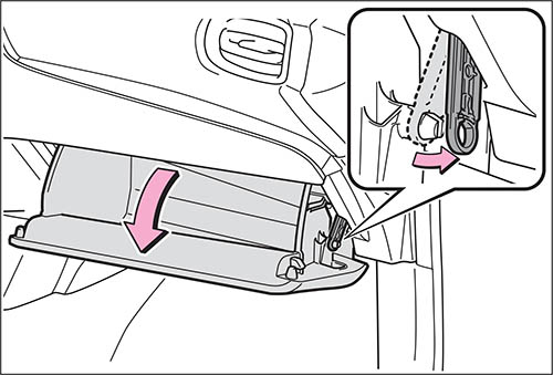
3.) Нажмите на перчаточный ящик с обеих сторон для отсоединения зубцов и затем медленно полностью откройте перчаточный ящик, поддерживая его.
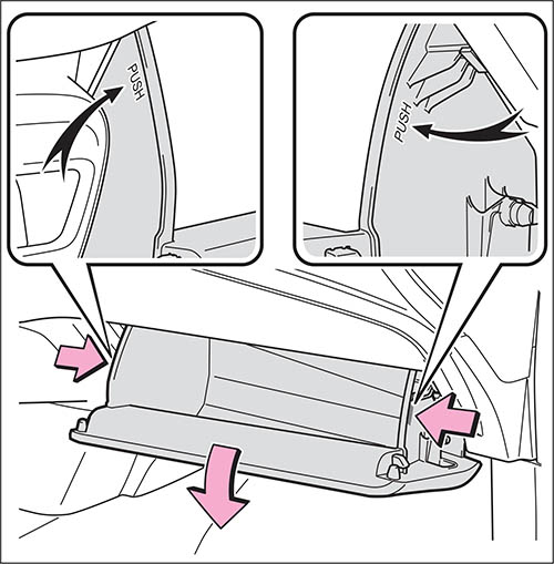
4.) Когда перчаточный ящик полностью открыт, слегка приподнимите его и потяните по направлению к сиденью для отсоединения нижней части ящика.
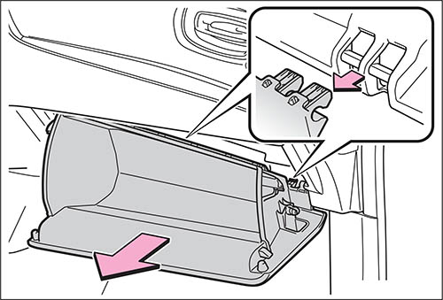
Если перчаточный ящик не отсоединяется, когда Вы тянете слегка, не прикладывайте излишнюю силу. Вместо этого потяните по направлению к сиденью, регулируя высоту перчаточного ящика.
5.) Снимите крышку фильтра.
Автомобили с левым рулем
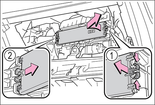
Автомобили с правым рулем
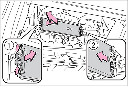
Разблокируйте крышку фильтра.
Переместите крышку фильтра в направлении стрелки, затем потяните ее, чтобы вынуть из зубцов.
6.) Снимите корпус фильтра.
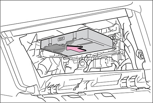
7.) Извлеките фильтр системы кондиционирования воздуха из корпуса фильтра и замените фильтр новым.
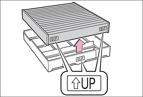
Метки «^UP» на фильтре должны быть обращены вверх.
8.) При установке выполняйте описанные шаги в обратном порядке.
■ Интервал проверки
Выполняйте осмотр и замену фильтра кондиционера в соответствии с графиком технического обслуживания. При эксплуатации автомобиля в регионах с повышенной запыленностью или на дорогах с интенсивным движением может потребоваться более ранняя замена.
■ Если поступление воздуха из вентиляционных дефлекторов заметно уменьшается
Фильтр мог засориться. Проверьте фильтр и при необходимости замените.
■ Фильтр кондиционера с функцией деодорирования
Если в автомобиль помещены сильно пахнущие вещества, эффект деодорирования может быть сильно ослаблен за короткий промежуток времени. Если запах из системы кондиционирования идет постоянно, замените фильтр кондиционера.
ВНИМАНИЕ!
■ При использовании системы кондиционирования воздуха
Убедитесь в наличии фильтра. Использование системы кондиционирования воздуха без фильтра может привести к повреждению системы.
■ При вынимании перчаточного ящика
Всегда следуйте указанной процедуре по снятию перчаточного ящика. Если перчаточный ящик вынимается без следования описанной процедуре, петля перчаточного ящика может быть повреждена.
■ Во избежание повреждения крышки фильтра

При перемещении крышки фильтра в направлении стрелки для разблокировки старайтесь не прикладывать излишнюю силу к зубцам. В противном случае зубцы могут быть повреждены.
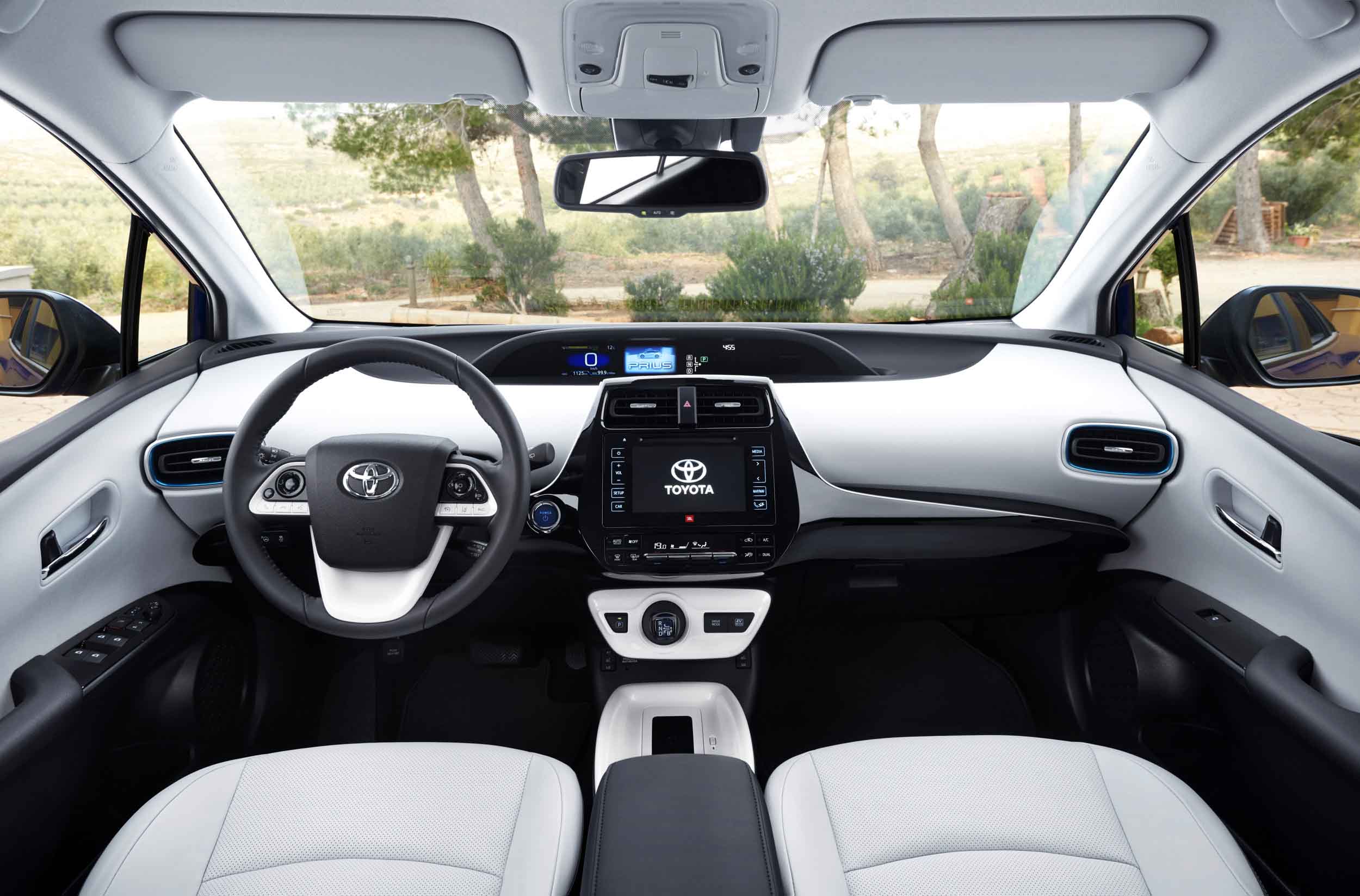
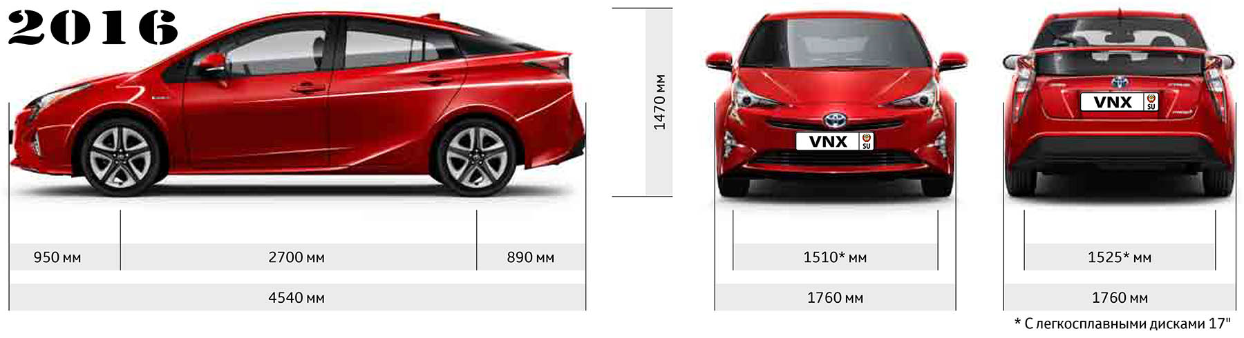
| № | Спецификация / Specs | Данные |
| Габариты (мм/mm) и масса (кг/kg) / Dimensions and Weight | ||
| 1 | Длина / Length | 4540 |
| 2 | Ширина (без/с зеркалами) / Width | 1760 |
| 3 | Высота (загружен/пустой) / Height | 1470-1490 (Не загруженный автомобиль) |
| 4 | Колёсная база / Wheelbase | 2700 |
| 5 | Дорожный просвет (клиренс) / Ground clearance | 136 |
| 6 | Снаряжённая масса / Total (curb) weight | 1375–1400 |
| Полная масса / Gross (max.) weight | 1790 | |
|
Двигатель / Engine |
||
| 7 | Тип / Engine Type, Code | Гибридный, бензиновый, жидкостного охлаждения, четырехтактный, 2ZR-FXE VVT-i (Atkinson cycle) и электрический 3JM |
| 8 | Количество цилиндров / Cylinder arrangement: Total number of cylinders, of valves | 4-цилиндровый, рядный, 16V, DOHC с верхним расположением двух распределительных валов |
| 9 | Диаметр цилиндра / Bore | 80.5 мм |
| 10 | Ход поршня / Stroke | 88.3 мм |
| 11 | Объём / Engine displacement | 1798 см³ |
| 12 | Система питания / Fuel supply, Aspiration | Распределенный впрыск топлива EFI |
| Атмосферный | ||
| 13 | Степень сжатия / Compression ratio | 13.04:1 |
| 14 | Максимальная мощность / Max. output power kW (HP) at rpm | 72 кВт (98 л.с.) при 5200 об/мин, электрический 72 л.с./53 кВт, Синергетический режим: 122 л.с./90 кВт |
| 15 | Максимальный крутящий момент / Max. torque N·m at rpm | 142 Нм при 3600 об/мин, электрический 163 Нм |
|
Трансмиссия / Transmission |
||
| 16 | Сцепление / Clutch type | Устройство распределения мощности PSD (Power Split Device) |
| 17 | КПП / Transmission type | Гибридная трансмиссия (e-CVT бесступенчатая трансмиссия с электронным управлением) |
О Книге
- Название: Toyota Prius Руководство для Владельца
- Бензиновые двигатели: 2ZR-FXE 1.8 л (1798 см³) 98 л.с./72 кВт и электрическими мотор-генераторами 72 л.с./53 кВт
- Выпуск с 2015 года
- Серия: «Owner Guide»
- Год издания: 2015
- Автор: Коллектив авторов
- Издательство: «Toyota Motors Corporation»
- Формат: PDF
- Страниц в книге: 729
- Размер: 51.09 МБ
- Язык: Русский
- Количество электросхем: 0
Инструкция на русском языке для Toyota Prius IV XW50 (2015 – нв), содержит справочные данные и описание основных моментов эксплуатации автомобиля.
Рекомендуем перед началом использования изучить руководство, это позволит избежать проблем при эксплуатации и узнать о всех функциях и особенностях автомобиля.
Информация о файле: 13.6 Мб, pdf
manual-toyota-prius-iv-xw50-2015-nv
◀Скачать руководство для Toyota HiAce H300 (2019 — нв)
Скачать Руководство для владельца Toyota Camry 2009 г▶