Главная
» 2018 » Февраль » 25 » Краткая инструкция пользователя Сигнал 20М
|
23:43 Краткая инструкция пользователя Сигнал 20М |
|
— Для взятия шлейфа под охрану требуется нажать кнопку с номером выбранного шлейфа (например мы хотим взять 1 шлейф под охрану: для этого на приборе существуют кнопки с номерами с 1 по 20. Чтобы взять первый шлейф под охрану, нажмите на кнопку с цифрой “1”) — Для снятия шлейфа с охраны требуется нажать кнопку с номером шлейфа, который будет сниматься с охраны. При срабатывании шлейфа пожарной сигнализации требуется посмотреть на лицевую сторону прибора и увидеть какой именно шлейф сработал (над кнопкой с номером будет мигать красный индикатор). Посмотреть в какой зоне сработала пожарная сигнализация (смотреть зоны требуется на расписке по шлейфам), принять меры в соответствии с внутренними правилами пожарной безопасности. При ложном срабатывании пожарной сигнализации требуется снять шлейф с охраны, а затем его поставить на охрану (способ снятия и взятия описан выше). Скачать инструкцию в формате Word >> |
|
Категория: Полезные статьи | Просмотров: 15992 | |
 Предлагаю скачать вот такую простую инструкцию по эксплуатации: Инструкция по пользованию прибором “Сигнал-20М”
-
Werkin
- Новичок
- Сообщения: 1
- Зарегистрирован: 23 окт 2013, 16:08
Сигнал 20м Краткая инструкция для персонала
Уважаемые коллеги, не поделитесь ли ссылкой на кратенькую инструкцию по использованию прибора Сигнал 20м для персонала?
Нужно простенько и доходчиво, без технической части
-
GenaSPB
- Модератор
- Сообщения: 10992
- Зарегистрирован: 20 апр 2010, 11:33
- Откуда: Санкт-Петербург
- Контактная информация:
Re: Сигнал 20м Краткая инструкция для персонала
Сообщение
GenaSPB » 23 окт 2013, 21:22
Вам только для Сигнала 20М без клавы? Вот для клавиатуры С2000 с оповещением на Блюзе. Думаю переработав ее сможете.
Инструкция по пользованию АПС и системой
оповещения людей о пожаре.
При возникновении пожара организовать эвакуацию и вызвать пожарную охрану. Далее действовать согласно должностным инструкциям.
При ложном срабатывании сигнализации:
1. Сброс тревог.
— Нажать клавишу «ON»
— Ввести код «1234»
— Выбрать «Сброс тревог» клавишами «▲▼»
— Нажать «Enter»
— Ввести адрес «N»
— Нажать «Enter»
— Выйти из режима нажимая «CLEAR» до появления часов
— Нажать «Сброс» на Базовом блоке «Блюз»
2. Постановка на охрану.
— Нажать клавишу «ON»
— Ввести код «1234»
— Выбрать «Взятие» клавишами «▲▼»
— Нажать «Enter»
— Выбрать «Взятие ШС» клавишами «▲▼»
— Нажать «Enter»
— Ввести адрес «N»
— Нажать «Enter»
— Ввести номер ШС
— Нажать «Enter»
— Выйти из режима нажимая «CLEAR» до появления часов
3. Снятие с охраны.
— Нажать клавишу «ON»
— Ввести код «1234»
— Выбрать «Снятие» клавишами «▲▼»
— Нажать «Enter»
— Ввести адрес «N»
— Нажать «Enter»
— Выбрать «Снятие ШС» клавишами «▲▼»
— Нажать «Enter»
— Ввести номер ШС
— Нажать «Enter»
— Выйти из режима нажимая «CLEAR» до появления часов
N- адрес прибора.
-
Рустам
- Специалист
- Сообщения: 3563
- Зарегистрирован: 10 май 2007, 06:59
- Откуда: Челябинск
Re: Сигнал 20м Краткая инструкция для персонала
Сообщение
Рустам » 24 окт 2013, 05:52
ИНСТРУКЦИЯ
по эксплуатации системы пожарной сигнализации, оповещения и управления эвакуацией здания … по адресу …
1. Сигнал о возникновении пожара выдается на блок индикации пожарного поста в виде мигающего свечения красным цветом индикатора соответствующего этажа здания с одновременной подачей непрерывного звукового сигнала. При получении этого сигнала необходимо действовать в соответствии с инструкцией дежурного персонала и инструкцией о мерах пожарной безопасности учреждения.
2. Система речевого оповещения автоматически запускается при получении сигнала «Пожар» для оповещения персонала учреждения и принятия мер к эвакуации людей из здания.
3. Сигнал о неисправности системы пожарной сигнализации выдается на блок индикации пожарного поста в виде мигающего свечения жёлтым цветом индикатора «неисправность». При получении этого сигнала необходимо вызвать представителей обслуживающей организации «…» по телефонам … или … для устранения неисправности.
4. При необходимости срочной эвакуации людей из здания ручной запуск системы оповещения производится нажатием клавиши «Оповещение» на блоке индикации пожарного поста. При необходимости остановки оповещения сброс осуществляется повторным нажатием клавиши «Оповещение».
5. Для определения причины сработки пожарной сигнализации при отсутствии пожара необходимо произвести визуальный осмотр оборудования системы соответствующего этажа здания. Сработка дымовых пожарных извещателей на потолке определяется по постоянному красному свечению их индикатора; сработка извещателей за подвесным потолком определяется по свечению светодиода оптического сигнализатора, расположенного на подвесном потолке под соответствующим извещателем; сработка ручного извещателя определяется по постоянному свечению красного индикатора и нажатому состоянию кнопки.
6. Сброс пожарной тревоги осуществляется автоматически после устранения причины срабатывания. Перевод ручных пожарных извещателей в дежурный режим осуществляется специальным ключом, хранящемся на пожарном посту.
Вернуться в «Инструкции и нормативные документы.»
Перейти
- Правила форума
- Если не зайти на форум
- Видеонаблюдение
- ↳ Общие вопросы по видеонаблюдению
- ↳ IP видеонаблюдение
- ↳ Аналоговые системы видеонаблюдения
- ↳ HD видеонаблюдение по коаксиальному кабелю (HD-SDI, AHD, HD-CVI и т.п.)
- ↳ FAQ. Основы видеонаблюдения.
- Оборудование из Китая (ebay, aliexpress, taobao, 409shop и т.п.)
- ↳ Помогите выбрать
- ↳ Оборудование из Китая — общие вопросы
- ↳ Восстановление и настройка
- ↳ Обзоры оборудования
- ↳ Отправка, доставка, гарантия, возврат
- Охранные и пожарные сигнализации, контроль доступа и прочие системы безопасности
- ↳ Охранные и пожарные сигнализации, пожаротушение и т.п.
- ↳ Контроль доступа, домофоны, учет рабочего времени.
- ↳ Турникеты, шлагбаумы, автоматические ворота.
- ↳ Монтаж
- ↳ Инструкции и нормативные документы.
- Все остальное
- ↳ Работа
- ↳ Предложения и запросы
- ↳ Курилка
Инструкция по пользованию прибором “Сигнал-20М”.
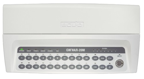
Прибор позволяет брать шлейфы на охрану и снимать их с охраны следующим способом:
— Для взятия шлейфа
под охрану требуется нажать кнопку с номером выбранного шлейфа
(например мы хотим взять 1 шлейф под охрану: для этого на приборе
существуют кнопки с номерами с 1 по 20. Чтобы взять первый шлейф под
охрану, нажмите на кнопку с цифрой “1”)
— Для снятия шлейфа с охраны требуется нажать кнопку с номером шлейфа, который будет сниматься с охраны.
При срабатывании шлейфа
пожарной сигнализации требуется посмотреть на лицевую сторону прибора и
увидеть какой именно шлейф сработал (над кнопкой с номером будет мигать
красный индикатор). Посмотреть в какой зоне сработала пожарная
сигнализация (смотреть зоны требуется на расписке по шлейфам), принять
меры в соответствии с внутренними правилами пожарной безопасности.
При ложном срабатывании пожарной сигнализации требуется снять шлейф с охраны, а затем его поставить на охрану (способ снятия и взятия описан выше).
-
Contents
-
Table of Contents
-
Bookmarks
Quick Links
SIGNAL-20M
ALARM CONTROL PANEL
User Guide
АЦДР.425513.017
2020
Related Manuals for bolid SIGNAL-20M
Summary of Contents for bolid SIGNAL-20M
-
Page 1
SIGNAL-20M ALARM CONTROL PANEL User Guide АЦДР.425513.017 2020… -
Page 2: Table Of Contents
TABLE OF CONTEXT 1. Description and Operation ……………………5 1.1 General …………………………5 1.2 Specifications ……………………….6 1.3 Standard delivery ……………………..7 1.4 Design and Operation ……………………… 9 1.4.1 General Information ……………………9 1.4.2 Inputs ……………………….10 1.4.3 Outputs ……………………….37 1.4.4 Credentials ……………………..
-
Page 3
This User Guide is meant for learning operation and usage principles of the Signal 20M (2.11) Alarm Control Panel (hereinafter referred to as the Panel ) Please read this Guide carefully before using this panel. Any maintenance, starting, configuring and running procedures must be performed in accordance with all requirements of norms and regulations at the installation site. -
Page 4: Description And Operation
1. Description and Operation General 1.1.1 The Signal-20M Intrusion and Fire Alarm Panel (hereinafter referred to as Panel) is designed to use as combined device to monitor and control alarms in the following systems: – Fire alarm and extinguishing systems –…
-
Page 5: Specifications
IPR 513-3M IP 67 Resettable Manual Call Point; – UDP 513-3M Manual Release Station The use of the above devices is guaranteed a complete compatibility with the Signal-20M in accordance with GOST R 53325-2012. In addition, the following intrusion detection devices manufactured by Bolid company are recommended for the operation with the Signal-20M: –…
-
Page 6: Standard Delivery
Table 1.3.1 Delivery Bundle Reference No Description Q.ty АЦДР.425513.017 Signal-20M Intrusion and Fire Alarm Control Panel 1 pcs. Set of spare parts and accessories : Resistor 0.5 W – 4,7 kΩ 24 pcs (MF 1/2W-4K7±5% or MF 1/2W-4K7±1% or similar ) Screw 1- 3х25.016 GOST 1144-80…
-
Page 7
Note: 1) –DS1990A dongles are optional delivery. 2) – The User Guide can be downloaded at the product page at www.bolid.ru… -
Page 8: Design And Operation
1.4.1 General Information 1.4.1.1 The Panel appearance, dimensions an installation layout are shown in 2.2.2. The Signal-20M’s enclosure has a removable cover, which can be removed to access the 1.4.1.2 connectivity elements. This contains the following items: – — terminals for connecting inputs (‘IN1 +’, ‘IN1-’ … ‘IN20 +’, ‘IN20-’) — 40 pcs .;…
-
Page 9: Inputs
1.4.2 Inputs 1.4.2.1 The control panel provides monitoring of 20 inputs for connecting fire (intrusion, alarm or auxiliary) input circuits with normally open/ closed internal contacts. Monitoring is based on the measuring of the input circuit resistance. 1.4.2.2 Device inputs can accommodate any types of intrusion and fire detectors designed to operate at constant voltage.
-
Page 10
– logic configuration parameters; – electrical resistance; – mode (armed (enabled) or disarmed (disabled), etc.). 1.4.2.11 In accordance with the logical state of the inputs, the panel: – displays their status on indicators ‘1’ … ‘20’; – controls the built-in buzzer when the inputs go into alarm states or when a fault occurs; –… -
Page 11
Table 1.4.2.1 Input Configuration Parameters (Input Attributes) Parameter Function Acceptable values range 1 – Smoke Fire (two-threshold) 2 – Combined Fire (one- threshold) 3 – Heat Fire (two-threshold) 4 – Intrusion 5 – Intrusion and Fire Defines the tactics of input monitoring, class of Input Type connected detectors and possible input states 6 –… -
Page 12
Never Disarm The input can never be disarmed Check/Uncheck Automating arming after arming failed status Check/Uncheck Rearming if Arming while the input is being restored Failed Automatically goes to the Arming status from Check/Uncheck the Intrusion Alarm and Panic states when Rearming After Alarm the input is restored (only for intrusion inputs of types 4, 5, 7 and 11) -
Page 13
(3.12) and lower; manually using the Signal-20M controls in standalone operation. The input enablement can be done only manually using the Signal-20M own controls or by a command of the network controller. If during attempt to arm the input, the resistance is less than normal, for example, a smoke detector triggering occurred in the input circuit, the control panel automatically resets input (turns off the power of this input for 3 seconds). -
Page 14
— DISARMED – manually using the panel controls or by the command of the network controller; — ARMED: manually using the panel controls or by the command of the network controller; automatically when the configuration parameter Reaming If Arming Failed is enabled, if the input resistance is in the normal range. -
Page 15
When switching to the PRE-ALARM state, the triggering of detectors on other inputs are also taken into account provided that they belong to the same zone. If upon triggering of a first or second detector of this input, the other input is already in the PRE-ALARM state and the detector on it was triggered no more than 120 seconds ago, this input goes to the FIRE state. -
Page 16
(3.12) and lower; manually using the Signal-20M controls, in standalone operation. The input enablement can be done manually only using the Signal-20M own controls or by a command of the network controller. If during an arming attempt, the input resistance is less than normal, for example, a smoke detector triggering occurred in the input circuit, the control panel automatically resets input (turns off the power of this input for 3 seconds). -
Page 17
In the ARMED state, the control panel monitors input circuit for short-circuit and open-circuit faults, triggering of heat detector and triggering of smoke detector. In case of input short/open circuit faults, the input goes to the SHORT CIRCUIT (OPEN- CIRCUIT) state, respectively. When the input is restored (if the resistance returns to the normal range), the input automatically goes to the ARMED state. -
Page 18
On the detector triggering, the input goes to the PRE-ALARM state. When switching to the PRE-ALARM state, the triggering of detectors on other inputs are also taken into account provided that they belong to the same zone. If upon smoke detector triggering on this input, the other input is already in the PRE-ALARM state and the detector on it was triggered no more than 120 seconds ago, this input goes to the FIRE state. -
Page 19
(3.12) and lower manually using the Signal-20M controls, in standalone operation The input enablement can be done manually only using the Signal-20M own controls or by the command of the network controller. If during attempt to arm the input, the resistance is beyond the normal range, the input immediately goes to the Arming Failed state. -
Page 20
In the PRE-ALARM state, the control of the input continues, and if the triggering of the second detector of this input is registered within the next 120 seconds, the input goes to the FIRE state. If the second detector does not trigger, or it does occur but 120 seconds later after switching to the PRE- ALARM, the input will remain in the PRE-ALARM state. -
Page 21
manually by the ARM or ENABLE command of the network controller (S2000M panel v.4.12 (3.12) and lower) manually using the Signal-20M controls when operated in combination with the S2000M control panel v.4.12 (3.12) and lower manually using the Signal-20M controls in standalone mode The input can be armed only manually using the panel controls or from the network controller. -
Page 22
After a delay as set in the Input Analysis Delay after Reset parameter, the device starts evaluating the input resistance. If after power reset, the input resistance is out of the normal range, the input goes into the ARMING state. If at input arming, the input-circuit resistance is higher than normal (open circuit), then the input immediately switches to ARMING FAILED state. -
Page 23
manually by the ARM or ENABLE command of the network controller (S2000M panel v.4.12 (3.12) and lower) manually using the Signal-20M controls when operated in combination with the S2000M control panel v.4.12 (3.12) and lower manually using the Signal-20M controls, in the standalone mode… -
Page 24
If a time of arming, the input-circuit resistance is not within normal or detector enclosure is open, the input immediately goes to the ARMING FAILED state. Being in the ARMING FAILED state, the input can be switched to the following states: — DISARMED –… -
Page 25
manually by the ARM or ENABLE command of the network controller (S2000M panel v.4.12 (3.12) and lower) manually using the Signal-20M controls when operated in combination with the S2000M control panel v.4.12 (3.12) and lower manually using the Signal-20M controls, in the standalone mode if the input resistance is beyond the normal range during the time longer than 3000 ms, the input goes to the AUX INPUT ACTIVE state. -
Page 26
Possible logical states of the input: – ARMED (ARMED, ENABLED) — the input is monitored, the circuit resistance is normal; – DISARMED (DISARMED) — the input is not monitored unless the disarmed input monitoring function is turned on; if such monitoring is enabled, the input is monitoring alarm and restoring of disarmed input see (Disarmed Input Monitoring) –… -
Page 27
Algorithm of Panic Input The logic operation and connection settings of intrusion Panic Input is the same as Type 4 Intrusion Input except for activation of the armed input switches it to the PANIC ALARM state. The Panic Alarm is displays on by LEDs of 1…20 inputs and impact to the relay with Alarm Output (10) and Alarm Output 2 (16) programs. -
Page 28
manually by the ARM or ENABLE command of the network controller (S2000M panel v.4.12 (3.12) and lower) manually using the Signal-20M controls when operated in combination with the S2000M control panel v.4.12 (3.12) and lower manually using the Signal-20M controls, in the standalone mode When enabled, states of the programmable aux input are depending on the input resistance changes and do not depend on any input parameters. -
Page 29
manually by ARM or ENABLE command of the network controller (S2000M panel v.4.12 (3.12) and lower) manually using the Signal-20M controls when operated in combination with the S2000M control panel v.4.12 (3.12) and lower; manually using the Signal-20M controls in standalone operation. -
Page 30
manually by the ARM or ENABLE command of the network controller (S2000M panel v.4.12 (3.12) and lower) manually using the Signal-20M controls when operated in combination with the S2000M control panel v.4.12 (3.12) and lower manually using the Signal-20M controls in standalone operation The monitoring of Input 17 can be disabled manually using panel controls or by the DISABLE command from the network controller. -
Page 31
manually, by the ARM or ENABLE command of the network controller (S2000M panel v.4.12 (3.12) and lower) manually, using the Signal-20M controls when operated in combination with the S2000M control panel v.4.12 (3.12) and lower; manually, using the Signal-20M controls in standalone operation. -
Page 32
Also, the monitoring of the input can be enabled manually using the panel controls or by the ARMED command of the network controller. In this case, from the DISARMED status, the input goes to the status corresponding to its current resistance. When the manual release is enabled, the input transition from one state to another (except for transition to ARMED and Disarmed) occurs in accordance with the resistance of the input at the moment. -
Page 33
ARMED state. This transition is possible only for intrusion inputs (types 4, 5, 7 and 11) and only if the Reaming after Alarm parameter is enabled; – the time during which the resistance of the auxiliary input (type 6) must be in the range AUX INPUT NORMAL for automatic transition from the state AUX INPUT ACTIVATED to AUX INPUT NORMAL –… -
Page 34
1.4.2.23 The Fire Input Requery Inhibit parameter allows to turn off requerying of smoke detectors on the Type 1 and Type 2 inputs. 1.4.2.24 The Debounce Time 300 ms defines the integration time fo intrusion inputs (Type 4, 5, 7 and 11). -
Page 35
R < 1,8 kΩ ot R > 12 kΩ, 2,2…10 kΩ Or resistance jump of more than 10 % Type 5 – Intrusion and Normal Intrusion Alarm Tamper Alarm Tamper R < 1,8 kΩ or 6,6…9,0 kΩ; R > 6,6 kΩ 2,2…5,4 kΩ… -
Page 36: Outputs
— 250 ms and less for all other types of inputs and for intrusion inputs, if the Debounce Time 300 ms parameter is enabled. Input disturbance for the time at which the device enters the alarm mode are: — 70 ms and more for intrusion inputs (input types 4,5,7 and 11), if the Debounce Time 300 ms parameter is disabled;…
-
Page 37
Electrical specifications of К1…К3 are provided in Table 1.4.3.1 1.4.3.4 Electrical specifications of К1…К3 Table 1.4.3.1 1 Description Value Output Type Dry contact (photo relay) DC switching voltage, no more, V Switching voltage of alternating current, no more, V Switching current (direct / alternating), no more, A Electrical Specifications of К4…К7 are provided in Table 1.4.3.2. -
Page 38
Parameter Function Values Simple Defines the algorithm for generating events Auxiliary Output Type that describe the current logical state of the output. Fire Protection 1 … 37, 50 … 53, Determines the tactics of local control of the 0 –Centralized Control (Network Control Program output depending on the state of the input connected to the output. -
Page 39
1.4.3.7 Output Type Parameter In the case of local control, the parameter determines the operation mode of the output state indicator (‘1’ … ‘7’), as well as the algorithm for generating events describing the current logical state of the output. These events are generated and transmitted to the network controller for all changes in the logical state of the output. -
Page 40
When the No Control is selected, the output is controlled through the network controller commands over RS-485 (centralized control). 1.4.3.12 The START / STOP buttons parameter defines the possibility of output manual control in the local control mode. When the START button is pressed, the Control Program is forced to start, regardless of the state of the inputs connected to the output, and when the STOP button is pressed, it is forced to stop. -
Page 41
The state of monitored output in the activated condition is determined the load current as described in table 1.4.3.5. Table 1.4.3.5 Monitored Output States in Activated Condition Output State Open Circuit Normal Open Circuit Load Current, А 0 … ‘open current ‘* ‘open current’* …… -
Page 42
– By commands of the network controller over RS-485 (centralized control). 1.4.3.19 The following shall be done to set local control for Output X: – Interlink output with required inputs (Output X parameter); – Set the Activation Delay for Output X for each interlinked input; –… -
Page 43
1.4.3.20 The local output control programs are described in table 1.4.3.6. Table 1.4.3.6 Local Output Control Programs Initial Control Program Description Condition No Control Centralized Control Turn on in case of Alarm, Flooding Alarm, or Fire*; Turn On Otherwise Turn off Turn off in case of Alarm, Flooding Alarm, or Fire*;… -
Page 44
Fire Lamp Blinking (0.25s On/0.25s Off) if Fire Blinking (0.25s On/0.75s Off) if Fire Pre-Alarm Blinking (0.5s On/0.5s Off) if Intrusion Alarm, Flooding Detected, Lobby Alarm or ARMING FAILED Blinking (0.25s On/1.75s Off) if Fault Turn On if all output-interlinked inputs are armed; Otherwise turn off. -
Page 45
Turn On if Level Increased Turn on if the input goes to the Level Increased state***; Otherwise turn off Turn On if Level Turn on if the input goes to the Level Decreased state***; Decreased Otherwise turn of Turn On for a set period of time, if Fire2; Turn On if Fire2 Otherwise, turn off Turn Off if Fire2… -
Page 46
The control programs with limited operation time (3, 4, 7, 8, 12, 50 – 53) are not resumed; Thus, the violation of auxiliary input of the Signal-20M suspense running general purpose programs with unlimited operation time and prohibits general purpose programs with limited operation time. -
Page 47: Credentials
1.4.4 Credentials 1.4.4.1 The panel allows using the following types of credentials: – -Touch Memory (iButton) electronic keys, operating on the Dallas Touch Memory interface (iButton); – PIN codes (codes, passwords). 1.4.4.2 The number of digits for different PIN codes may be different. The minimum is 2 digits.
-
Page 48
Using the program ‘Uprog.exe’, you can set two or more credentials of the ‘Administrator’ type. The current version of the program ‘Uprog.exe’ is available on Bolid’s website: at bolid.ru in the section ‘Software’. To configure the credentials stored in the panel, the panel must be connected to a computer with the installed ‘Uprog.exe’… -
Page 49: Operation Modes
The current version of the program ‘Uprog.exe’ is available on Bolid’s website: at bolid.ru in the section ‘Software’. To configure the credentials stored in the panel, the panel must be connected to a computer with the installed ‘Uprog.exe’ program through one of the interface converters (‘PI-GR’, ‘S2000- PI’, ‘S2000-USB’…
-
Page 50
1.4.5.4 The control panel monitors the logical states of all inputs in accordance with their type, configuration parameters, resistance and mode (armed (enabled) or disarmed (disabled)). For more information, see ‘Inputs’. 1.4.5.5 The control panel monitors the states of outputs in accordance with their type, configuration parameters and mode (on / off). -
Page 51
(control panel ‘S2000M’ v.4.13 and higher); – disables monitoring and control of any outputs (S2000M v.4.13 and higher). 1.4.5.13 From the Quiescent mode, the Signal-20M can go to the following modes: – PIN Code Entry;… -
Page 52
– monitors the state of the power inputs; – monitors the condition of the enclosure; – generates events about all changes in the device elements (inputs, outputs, housing and power inputs); – controls the light and sound indication corresponding to the current state of the panel elements (inputs, outputs, housing and power inputs);… -
Page 53
1.4.5.24 In the Local Control mode, the panel: – monitors logical states of the inputs; – monitors the status of the outputs; – controls the outputs depending on the current state of the inputs (locally); – monitors the state of the power inputs; –… -
Page 54
Initiates an arming attempt, if the input is disarmed and it is possible Disarms an input if it is NOT disarmed and it is possible to disarm; otherwise, if it is possible to arm an input, an arming will be attempted. -
Page 55
The program is blocked (inhibited) blocked as long as the conditions for its start are preserved (corresponding to the states of the inputs associated with this output). The program can be resumed: — manually, by pressing the button START button again; — automatically, after resetting the alarm states of all inputs and the subsequent repeated activation of at least one input associated with this output (i.e., the repeated occurrence of the program run condition). -
Page 56
1.4.5.42 When the Touch Memory credential is presented to the reader (or password is entered), the panel transmits the credential code to the network controller and waits a response about the control rights to this credential. At this moment, the ‘Access’ indicator switches from red to green with a frequency of 4 Hz. The process of waiting for a response can take from fractions of a second to several seconds, depending on the number of devices in the RS-485 interface 1.4.5.43 If the presented credential has no rights, the control panel indicates a Deny in access to… -
Page 57
Suspend User Credential Suspend User Credential by Number Restore User Credential Restore User Credential by Number Delete User Credential Delete User Credential by Number View Number of User Credential Test Light and Sound Indication Change Administrator Credential Delete All User Credentials 1.4.5.51 If no item is selected during 20 seconds after entering menu, the panel returns back to the Quiescent mode. -
Page 58
For example, when you add a credential and save it under No. 3, the number will be displayed by turning green the following indicators: “10” — “10” — “3” –––– “10” — “10” — “3” –––– “10” — “10” — “3”. And when you add a Touch Memory token (or PIN-code), and save it under No. -
Page 59
After presenting a token (entering the PIN-code), the panel displays the rights of this credential on its indicators. The input control rights are display by corresponding indicators ‘1’ … ‘20’, as described in Table 1.4.4.4. Table 1.4.4.4 Input Control Rights Indication Rights Indicator (LED) Illumination (‘1’… -
Page 60
1.4.5.54 The Edit User Credential by Number allows editing user credential rights for arming and disarming individual inputs. It differs from the Edit User Credential by need to specify the credential number to edit the its rights without presenting the credential itself. When the specified menu item is selected, the “13”… -
Page 61
– press the ‘Enter’ button again. If the length of the entered PIN-code is equal to the maximum possible, pressing the Enter button is not required. The maximum possible length of the PIN-code is determined by the Maximum PIN Length configuration parameter (see 1.4.7.). Double entry of the PIN-code eliminates a wrong entry. -
Page 62
After entering a credential, the panel displays the rights of this credential on its indicators. The procedures for displaying, editing and saving user credential rights are the same as described in the Edit User Credential Rights menu. Errors possible during editing are similar to the errors described in the Edit User Credential Rights menu. -
Page 63
After successful suspension or error code indication, the panel returns to the ‘Administrator Menu’ mode. If, within 20 seconds after selecting a menu item, the credential is not presented, the panel will return to the Quiescent mode. Return to the Quiescent mode is accompanied by a short triple beep. 1.4.5.57 The Suspend User Credential by Number allows suspending a user credential without deleting it from the memory. -
Page 64
The panel displays an error code for 3 seconds by turning red a corresponding indicator in the intermittent mode. For example, if the error code is 2, the indicator ‘2’ is turned intermittent red for 3 seconds The error code display is accompanied by a long beep. The error saving credential may occur in case of attempt to restore Administrator or Installers credentials (use specific menus for that purpose) or due to hardware failures. -
Page 65
When trying to delete a user credential, errors may occur. Description of these errors is provided in Table 1.4.4.10. Table 1.4.4.10 Credential Deleting Errors Description Error Code (Indicator No) The presented credential does not exist in the memory (or deleted) Error saving credential Too short PIN (less than 2 digits) If an error occurs while deleting a credential, the indicators ‘20’… -
Page 66
To view a user’s PIN number, the following shall be done: – enter this PIN-code using buttons ‘1’ … ‘10’ (button ‘10’ corresponds to number ‘0’); – press the Enter button. If the length of the entered PIN-code is equal to the maximum possible — pressing the Enter button is not required. -
Page 67
In addition, the administrator credential shall be changed if it is compromised. There are no restrictions on type of credential to replace an administrator credential, in other words it can be a Touch Memory (iButton) token or PIN code. When this menu item is selected, “7” indicator turns continuous green, and the “Access” indicator turns on with an intermittent green color (an invitation to enter a PIN code or present a token). -
Page 68
To delete a user’s PIN code, you must: – enter this PIN-code using buttons ‘1’ … ‘10’ (button ‘10’ corresponds to number ‘0’); After first pressing the Enter button, indicator “6” turns blinking green. The second pressing the Enter button deletes all user credentials. To cancel deleting all credential and return the panel to the Quiescent mode, press the Key button. -
Page 69
The switching to the Indication Test is accompanied by the ‘Test’ melody. In this mode, all monochromatic indicators are always on, and bi-color indicators are switching from red to green. The indication test lasts 15 s. After completion of the indication test, the device automatically returns to the Quiescent mod 1.4.5.68 The can be switched to the Installer menu by the following way:… -
Page 70
After the second press of the Enter button, the network address and the response pause will be changed. After 5 short beeps, the panel will return to the Installer menu. To cancel the reset of the network address, response pause and to return the panel to Quiescent mode, press the Key button. -
Page 71
When the specified menu item is selected, indicator “13” turns on steady red, and the “Access” indicator turns off. To change the network address, the following shall be done must: — enter a new network address (available values 1 … 127) using buttons ‘1’ … ‘10’ (button ‘10’ corresponds to number ‘0’);… -
Page 72
Table 1.4.4.16.1 “4” … “7” Output State Indication during Test Procedures Indicator Operation (2 s cycle) Output State Output ON NORMAL Output OFF Alternating intermittent sequence: Yellow: 0.125 s – On; 0.125 s – Off; 0.125 s – On; 1.625 s – Off (0.5 Hz); Output ON and red: 0.5 s –… -
Page 73
1.4.5.76 The Bootloader allows you to manually switch the panel to the Device Failed mode (bootloader mode). This can be useful in case of difficulties arising when trying to update the firmware of the panel with specialized programs (‘Uprog.exe’, etc.). When the specified menu item is selected, the “17”… -
Page 74: Light And Sound Indication
When trying to replace an admin credential, errors may occur. Description of errors is provided in Table 1.4.4.17. Table 1.4.4.17 Installer Credential Replacement Errors Error Code Description (Indicator No) A presented credential already exists Entered PIN codes mismatches Error saving an installer credential Too short PIN code (less than 2 digits) If an error occurs while replacing a credential, the indicators ‘19’…
-
Page 75
The states indication for inputs “1” … “20” is described in Table 1.4.6.1. 1.4.6.2 Table 1.4.6.1 Indicator Operation Modes “1” … “20” Indicator Operation Mode Input State (2 sec Cycle) DIARMED , ARMED , RCU RESTORED ,PUMP OFF TAMPER NORMAL DISABLED, Yellow ON DISARMED,… -
Page 76
Indicator Operation Modes “1” … “20” (continued) Table 1.4.6.1 Indicator Operation Modes Input States (2s Cycle) Intermittent Green Sequence TEMPERATURE LOW , LEVEL 0.5 с – ON; 0.5 с – ON (1 Гц) DECREASED AUX INPUT ACTIVATED 2 Intermittent Yellow Sequence 0.125 s –… -
Page 77
Table 1.4.6.3 Monitored Output States Indication Modes: Fire Protection Outputs “ 4” … “7” Indicator Operation Modes Fire Protection Output State (2-second Cycle) Output Activated NORMAL Output not active Output Alternative intermittent Yellow: 0.125s – ON; 0.125s – OFF; Activated 0.125s –… -
Page 78
Table 1.4.6.5 Monitored Output States Indication Modes: Simple Outputs “4” … “7” Indicator Operation Modes Simple Output State (2-second Cycle) NORMAL Intermittent Yellow 0.125 s – ON; 0.125 s – OFF; OPEN CIRCUIT 0.125 s – ON; 1.6255 s – OFF (0.5 Hz) Intermittent yellow 0.125 s –… -
Page 79
Table 1.4.6.7 FIRE Indicator Operation Indicator Operation Modes (2-second Cycle) Input State FIRE2 Intermittent Red 0,25 с – включен; 0,25 с – выключен (2 Гц) FIRE К К К К К К К К Прерывистые включения красным цветом 1 с – включен; 1 с – выключен (0,5 Гц) PRE-ALARM No fire alarms 1.4.6.6… -
Page 80
1.4.6.8 The DISABLED system indicator operation modes are described in Table 1.4.6.10. Table 1.4.6.10 DISABLED Indicator Operation Mode Indicator Operation Modes Input (output) states (two-second cycle) DISARMED Yellow DISABLED, OUTPUT MONITORING DISABLED No disabled inputs Notes: 1) only for Fire inputs (1, 2, 3, 16 and 18) 2) the output control and monitoring is disabled by the command from the network controller (the disablement of output monitoring in the configuration parameter does not affect the indicator operation) -
Page 81
1.4.6.11 The STOP system indicator operation modes are provided in Table 1.6.13. Table 1.4.6.13 The STOP Indicator Operation Modes Indicator Operation Modes Panel Output States (two-second cycle) One or more Fire Protection Yellow outputs are deactivated manually (using the STOP button) No manually deactivated (by STOP) Fire Protection outputs… -
Page 82
1.4.6.12 The ACCESS indicator operation modes are described in Table 1.4.6.14. Table 1.4.6.14 Access Indicator Operation Modes Indicator Operation Modes Panel Operation Mode (two-second cycle) Intermittent Green Sequence PIN Code Entry 0.125 s – ON; 0.125 s – OFF (4 Hz) (invitation to enter PIN) Green Local Control… -
Page 83
1.4.6.13 The Mute indicator operation modes are described in Table 1.4.6.15. Table 1.4.6.15 Buzzer status indicator Indicator Operation Modes (two-second cycle) Buzzer condition Yellow Muted Muted or no sounds 1.4.6.14 The Buzzer operation modes are described in Table 1.4.6.16. The modes are specified from highest to the lowest priority – the Awake is the highest priority mode, the Off is the lowest one. -
Page 84: Panel Configuration Parameters
The configuration parameters can be set using the ‘Uprog.exe’ program. The current 1.4.7.2 version of the program ‘Uprog.exe’ is available on the Bolid’s website: at www.bolid.ru in the Software section. To configure the product, it must be connected to a computer with installed ‘Uprog.exe’…
-
Page 85: Instruments, Tools And Accessories
1.4.7.3 The Panel system parameters are described in Table 1.4.7.1. Table 1.4.7.1 Panel System Parameters Parameter Function Acceptable Values Defines maximum credential length 2 — 12 Maximum PIN Length Prohibit Factory Prohibits/Permits reset to default values Checked/Unchecked (default) Reset Two Power Inputs Defines whether both power input shall be Checked/Unchecked monitored…
-
Page 86: Marking And Sealing
Table 1.5.1 Instruments, tools and accessories Name Description Measurement of AC and DC voltage up to 500V, current up to 5A, Digital multimeter resistance up to 2 MΩ 3.0х50 mm Flat screwdriver Phillips screwdriver 2×100 mm Side cutter 160 mm Pliers 160 mm Marking and Sealing…
-
Page 87: Intendent Usage
2. Intendent Usage Usage Limitations The control panel is not designed to be used in aggressive environments, dust and explosive and fire hazards premises. Preparing for Use 2.2.1 Safety Measures before Starting: – the product design meets the requirements of electrical and fire safety in accordance with GOST 12.2.007.0-75 and GOST 12.1.004-91;…
-
Page 88
2.2.2 Product Design The appearance, dimensions and installation layout are shown in Figure 2.1. Figure 2.1 Appearance, Dimensions, and Installation Layout… -
Page 89
2.2.3 Installation 2.2.3.1 The control panel is installed on walls or other structures of the protected premises in places protected from atmospheric precipitation and mechanical damage. 2.2.3.2 During installation, it is necessary to fix the device on the wall in a convenient place. If the device is installed in an unprotected room, it is recommended to install it at a height of at least 2.2 m from the floor. -
Page 90
The panel connections shall be in accordance with the electric diagram provided in Figure 2.2. Figure 2.2 Connection Electric Diagram 2.2.4.2. To connect the Signal-20M to the RS-485 interface line (if needed): – contacts ‘A’ and ‘B’ are connected respectively to lines A and B of the RS-485 interface; –… -
Page 91
Connection of normally open (smoke) detectors Connection of normally closed and normally open intrusion detectors to Type 4 Input (Intrusion) and to Type 1 Input (Fire Smoke Two-Threshold) Type 4 Input (Lobby), and Type 11 (Panic) ШСx INх 4,7 кОм 4,7 кОм… -
Page 92
Connection of IP 435-8/101-04-А1R ‘SOnet’ To Type 1 Input (above) and Type 2 Input (bellow) Connection of IPR 513-3M (call points) to Type 16 Input and UDP 513-3М manual stations (RCU) to Type 18 Inputs… -
Page 93
Figure 2.3. Connection of Initiating Devices to Panel Input Circuits (continued) Connection of thermal cable to Type 2 Input INх+ INх — Junction Junction Ra – additional resistor to be connected directly to thermal cable (thermal cable connection terminals); Rtc – thermal cable resistance as specified in its technical documents. Maximum acceptable resistance value is 1,5K Ω;… -
Page 94
This type of connection allows monitoring the health of the communication line with an alarm device (actuator) both in active and inactive states. In the inactive state, the terminal element (resistor 4.7 kΩ) is monitored using a small current of reverse polarity. -
Page 95
— Output Current Drop Check. Other control options are not allowed. When a terminal element (resistor 4.7 kΩ) is placed out outside the alarm device (actuator) housing, the Activated Output Monitoring parameter shall be set as Regular Off-Load Check. Other monitoring options are not allowed in this case. 2.2.4.6. -
Page 96
Actuator 1 Actuator 2 Кх+ Кх — 1N5400 1N5400 Rн Rн Actuator n 4.7 кhm 1N5400 Rн , where x is output number (4 … 7) Figure 2.7 Connection of several nonpolar actuators to one panel output This connection type is not applied to extinguishant release circuits: pyrotechnical cartridges, locking devices and other devices with low resistance (single- or two- digit ohms). -
Page 97
2.2.4.8. The extinguishing release circuit device are connected as shown in Figure 2.8: Extinguishant Release Circuit 1N5400 Кх+ Кх — 4,7 кОм Rн , where x is output number (4 … 7) Figure 2.8. Connection of extinguishant release circuit device The connection types allow connection of one extinguishant release circuit device: pyrotechnical cartridge, locking device or other device which has small resistance (single- or two- digit ohms). -
Page 98
2.2.5 Panel Settings 2.2.5.1. The Signal-20M configuration parameters are specified in Table 2.1. Table 2.1 Signal-20M Default Configuration Parameters Inputs № NOTES: 15 – Rearming after Arming Failed а) The figures means the following parameters: 16 – Rearming after Alarm 1 –… -
Page 99
Activated Output Monitoring: 0 – Normal Control Program: 9 – Lamp; 10 – Alarm Output1; 12 – Siren; 2.2.5.3. The Signal-20M default parameters are specified in Table 2.3. Table 2.3 Default system parameters Parameter Value Maximum PIN Length Prohibit Factory Reset Uncheck… -
Page 100
(mandatory) of updating are posted on the Internet at the bolid.ru website on the page of the Signal-20M device on the Download tab To update the software, the device must be connected to a computer via one of the interface converters (‘PI-GR’, ‘S2000-PI’, ‘S2000-USB’… -
Page 101: Use Of Product
– functionality check in accordance with clause 3.4 of this manual. – Maintenance is recommended to be carried out using the methodological manual ‘Maintenance of fire alarm systems and SOUE type 1-2 in Orion ISS that can found at: bolid.ru. Attention! Removing the panel print circuit board from the enclosure will automatically void the manufacturer’s warranty.
-
Page 102
3.4.2 If necessary, during on-receipt inspection, a full functional check can be carried out. The full verification method is described in 3.4.2.1 — 3.4.2.22. 3.4.3 A complete check of the product’s performance during the on-receipt inspection is carried out by persons who read carefully this manual, understand the principle of the product’s operation, and have an electrical Safety Qualification of Class II, at least. -
Page 103
3.4.7.5 Press the session start / end button. 3.4.7.6 Enter the Administrator password (by default ‘1234’) and press the Enter button 3.4.7.7 In the Administrator menu, select the ‘Indication Test’ item by pressing the button ______. 3.4.7.8 Switching to the ‘Indication Test’ is accompanied by the ‘Test’ melody Make sure that all single-color LEDs are always on and bi-color LEDs are switching from red to green. -
Page 104: Technical Examination
3.5 Technical examination There is no technical inspection of the product. 3.6 Preservation (de-preservation, re-preservation) Preservation of the product is not provided.
-
Page 105: Repairs
8. Manufacturer Warranty The manufacturer guarantees that the Signal-20M panel meets with technical requirements if the user follows the instructions for shipment, storage, installation, and usage. Warranty period is 18 months but no more than 24 months from the manufacturer’s date of issue.
-
Page 106: Certificates
Compatibility of Technical Means’ (TR TS 020/2011). Has a declaration of conformity: EAC No. RU D-RU.HP15.B.06633 / 20. 9.3 The Signal-20M fire and intrusion alarm control panel is a part of the Orion addressable fire alarm system which has a certificate of conformity No. BY / 112 02.01.033 00573, issued by the Institution ‘Republican Center for Certification and…
Перейти к контенту
Главная
» 2018 » Февраль » 25 » Краткая инструкция пользователя Сигнал 20М
|
23:43 Краткая инструкция пользователя Сигнал 20М |
|
— Для взятия шлейфа под охрану требуется нажать кнопку с номером выбранного шлейфа (например мы хотим взять 1 шлейф под охрану: для этого на приборе существуют кнопки с номерами с 1 по 20. Чтобы взять первый шлейф под охрану, нажмите на кнопку с цифрой “1”) — Для снятия шлейфа с охраны требуется нажать кнопку с номером шлейфа, который будет сниматься с охраны. При срабатывании шлейфа пожарной сигнализации требуется посмотреть на лицевую сторону прибора и увидеть какой именно шлейф сработал (над кнопкой с номером будет мигать красный индикатор). Посмотреть в какой зоне сработала пожарная сигнализация (смотреть зоны требуется на расписке по шлейфам), принять меры в соответствии с внутренними правилами пожарной безопасности. При ложном срабатывании пожарной сигнализации требуется снять шлейф с охраны, а затем его поставить на охрану (способ снятия и взятия описан выше). Скачать инструкцию в формате Word >> |
|
Категория: Полезные статьи | Просмотров: 15656 | |
-
Werkin
- Новичок
- Сообщения: 1
- Зарегистрирован: 23 окт 2013, 16:08
Сигнал 20м Краткая инструкция для персонала
Уважаемые коллеги, не поделитесь ли ссылкой на кратенькую инструкцию по использованию прибора Сигнал 20м для персонала?
Нужно простенько и доходчиво, без технической части
-
GenaSPB
- Модератор
- Сообщения: 10970
- Зарегистрирован: 20 апр 2010, 11:33
- Откуда: Санкт-Петербург
- Контактная информация:
Re: Сигнал 20м Краткая инструкция для персонала
Сообщение
GenaSPB » 23 окт 2013, 21:22
Вам только для Сигнала 20М без клавы? Вот для клавиатуры С2000 с оповещением на Блюзе. Думаю переработав ее сможете.
Инструкция по пользованию АПС и системой
оповещения людей о пожаре.
При возникновении пожара организовать эвакуацию и вызвать пожарную охрану. Далее действовать согласно должностным инструкциям.
При ложном срабатывании сигнализации:
1. Сброс тревог.
— Нажать клавишу «ON»
— Ввести код «1234»
— Выбрать «Сброс тревог» клавишами «▲▼»
— Нажать «Enter»
— Ввести адрес «N»
— Нажать «Enter»
— Выйти из режима нажимая «CLEAR» до появления часов
— Нажать «Сброс» на Базовом блоке «Блюз»
2. Постановка на охрану.
— Нажать клавишу «ON»
— Ввести код «1234»
— Выбрать «Взятие» клавишами «▲▼»
— Нажать «Enter»
— Выбрать «Взятие ШС» клавишами «▲▼»
— Нажать «Enter»
— Ввести адрес «N»
— Нажать «Enter»
— Ввести номер ШС
— Нажать «Enter»
— Выйти из режима нажимая «CLEAR» до появления часов
3. Снятие с охраны.
— Нажать клавишу «ON»
— Ввести код «1234»
— Выбрать «Снятие» клавишами «▲▼»
— Нажать «Enter»
— Ввести адрес «N»
— Нажать «Enter»
— Выбрать «Снятие ШС» клавишами «▲▼»
— Нажать «Enter»
— Ввести номер ШС
— Нажать «Enter»
— Выйти из режима нажимая «CLEAR» до появления часов
N- адрес прибора.
-
Рустам
- Специалист
- Сообщения: 3536
- Зарегистрирован: 10 май 2007, 06:59
- Откуда: Челябинск
Re: Сигнал 20м Краткая инструкция для персонала
Сообщение
Рустам » 24 окт 2013, 05:52
ИНСТРУКЦИЯ
по эксплуатации системы пожарной сигнализации, оповещения и управления эвакуацией здания … по адресу …
1. Сигнал о возникновении пожара выдается на блок индикации пожарного поста в виде мигающего свечения красным цветом индикатора соответствующего этажа здания с одновременной подачей непрерывного звукового сигнала. При получении этого сигнала необходимо действовать в соответствии с инструкцией дежурного персонала и инструкцией о мерах пожарной безопасности учреждения.
2. Система речевого оповещения автоматически запускается при получении сигнала «Пожар» для оповещения персонала учреждения и принятия мер к эвакуации людей из здания.
3. Сигнал о неисправности системы пожарной сигнализации выдается на блок индикации пожарного поста в виде мигающего свечения жёлтым цветом индикатора «неисправность». При получении этого сигнала необходимо вызвать представителей обслуживающей организации «…» по телефонам … или … для устранения неисправности.
4. При необходимости срочной эвакуации людей из здания ручной запуск системы оповещения производится нажатием клавиши «Оповещение» на блоке индикации пожарного поста. При необходимости остановки оповещения сброс осуществляется повторным нажатием клавиши «Оповещение».
5. Для определения причины сработки пожарной сигнализации при отсутствии пожара необходимо произвести визуальный осмотр оборудования системы соответствующего этажа здания. Сработка дымовых пожарных извещателей на потолке определяется по постоянному красному свечению их индикатора; сработка извещателей за подвесным потолком определяется по свечению светодиода оптического сигнализатора, расположенного на подвесном потолке под соответствующим извещателем; сработка ручного извещателя определяется по постоянному свечению красного индикатора и нажатому состоянию кнопки.
6. Сброс пожарной тревоги осуществляется автоматически после устранения причины срабатывания. Перевод ручных пожарных извещателей в дежурный режим осуществляется специальным ключом, хранящемся на пожарном посту.
Вернуться в «Инструкции и нормативные документы.»
Перейти
- Правила форума
- Если не зайти на форум
- Видеонаблюдение
- ↳ Общие вопросы по видеонаблюдению
- ↳ IP видеонаблюдение
- ↳ Аналоговые системы видеонаблюдения
- ↳ HD видеонаблюдение по коаксиальному кабелю (HD-SDI, AHD, HD-CVI и т.п.)
- ↳ FAQ. Основы видеонаблюдения.
- Оборудование из Китая (ebay, aliexpress, taobao, 409shop и т.п.)
- ↳ Помогите выбрать
- ↳ Оборудование из Китая — общие вопросы
- ↳ Восстановление и настройка
- ↳ Обзоры оборудования
- ↳ Отправка, доставка, гарантия, возврат
- Охранные и пожарные сигнализации, контроль доступа и прочие системы безопасности
- ↳ Охранные и пожарные сигнализации, пожаротушение и т.п.
- ↳ Контроль доступа, домофоны, учет рабочего времени.
- ↳ Турникеты, шлагбаумы, автоматические ворота.
- ↳ Монтаж
- ↳ Инструкции и нормативные документы.
- Все остальное
- ↳ Работа
- ↳ Предложения и запросы
- ↳ Курилка
Инструкция по пользованию прибором “Сигнал-20М”.
Прибор позволяет брать шлейфы на охрану и снимать их с охраны следующим способом:
— Для взятия шлейфа
под охрану требуется нажать кнопку с номером выбранного шлейфа
(например мы хотим взять 1 шлейф под охрану: для этого на приборе
существуют кнопки с номерами с 1 по 20. Чтобы взять первый шлейф под
охрану, нажмите на кнопку с цифрой “1”)
— Для снятия шлейфа с охраны требуется нажать кнопку с номером шлейфа, который будет сниматься с охраны.
При срабатывании шлейфа
пожарной сигнализации требуется посмотреть на лицевую сторону прибора и
увидеть какой именно шлейф сработал (над кнопкой с номером будет мигать
красный индикатор). Посмотреть в какой зоне сработала пожарная
сигнализация (смотреть зоны требуется на расписке по шлейфам), принять
меры в соответствии с внутренними правилами пожарной безопасности.
При ложном срабатывании пожарной сигнализации требуется снять шлейф с охраны, а затем его поставить на охрану (способ снятия и взятия описан выше).
Перейти к контенту

Главная
» 2018 » Февраль » 25 » Краткая инструкция пользователя Сигнал 20М
|
23:43 Краткая инструкция пользователя Сигнал 20М |
|
— Для взятия шлейфа под охрану требуется нажать кнопку с номером выбранного шлейфа (например мы хотим взять 1 шлейф под охрану: для этого на приборе существуют кнопки с номерами с 1 по 20. Чтобы взять первый шлейф под охрану, нажмите на кнопку с цифрой “1”) — Для снятия шлейфа с охраны требуется нажать кнопку с номером шлейфа, который будет сниматься с охраны. При срабатывании шлейфа пожарной сигнализации требуется посмотреть на лицевую сторону прибора и увидеть какой именно шлейф сработал (над кнопкой с номером будет мигать красный индикатор). Посмотреть в какой зоне сработала пожарная сигнализация (смотреть зоны требуется на расписке по шлейфам), принять меры в соответствии с внутренними правилами пожарной безопасности. При ложном срабатывании пожарной сигнализации требуется снять шлейф с охраны, а затем его поставить на охрану (способ снятия и взятия описан выше). Скачать инструкцию в формате Word >> |
|
Категория: Полезные статьи | Просмотров: 15643 | |
-
Werkin
- Новичок
- Сообщения: 1
- Зарегистрирован: 23 окт 2013, 16:08
Сигнал 20м Краткая инструкция для персонала
Уважаемые коллеги, не поделитесь ли ссылкой на кратенькую инструкцию по использованию прибора Сигнал 20м для персонала?
Нужно простенько и доходчиво, без технической части
-
GenaSPB
- Модератор
- Сообщения: 10970
- Зарегистрирован: 20 апр 2010, 11:33
- Откуда: Санкт-Петербург
- Контактная информация:
Re: Сигнал 20м Краткая инструкция для персонала
Сообщение
GenaSPB » 23 окт 2013, 21:22
Вам только для Сигнала 20М без клавы? Вот для клавиатуры С2000 с оповещением на Блюзе. Думаю переработав ее сможете.
Инструкция по пользованию АПС и системой
оповещения людей о пожаре.
При возникновении пожара организовать эвакуацию и вызвать пожарную охрану. Далее действовать согласно должностным инструкциям.
При ложном срабатывании сигнализации:
1. Сброс тревог.
— Нажать клавишу «ON»
— Ввести код «1234»
— Выбрать «Сброс тревог» клавишами «▲▼»
— Нажать «Enter»
— Ввести адрес «N»
— Нажать «Enter»
— Выйти из режима нажимая «CLEAR» до появления часов
— Нажать «Сброс» на Базовом блоке «Блюз»
2. Постановка на охрану.
— Нажать клавишу «ON»
— Ввести код «1234»
— Выбрать «Взятие» клавишами «▲▼»
— Нажать «Enter»
— Выбрать «Взятие ШС» клавишами «▲▼»
— Нажать «Enter»
— Ввести адрес «N»
— Нажать «Enter»
— Ввести номер ШС
— Нажать «Enter»
— Выйти из режима нажимая «CLEAR» до появления часов
3. Снятие с охраны.
— Нажать клавишу «ON»
— Ввести код «1234»
— Выбрать «Снятие» клавишами «▲▼»
— Нажать «Enter»
— Ввести адрес «N»
— Нажать «Enter»
— Выбрать «Снятие ШС» клавишами «▲▼»
— Нажать «Enter»
— Ввести номер ШС
— Нажать «Enter»
— Выйти из режима нажимая «CLEAR» до появления часов
N- адрес прибора.
-
Рустам
- Специалист
- Сообщения: 3536
- Зарегистрирован: 10 май 2007, 06:59
- Откуда: Челябинск
Re: Сигнал 20м Краткая инструкция для персонала
Сообщение
Рустам » 24 окт 2013, 05:52
ИНСТРУКЦИЯ
по эксплуатации системы пожарной сигнализации, оповещения и управления эвакуацией здания … по адресу …
1. Сигнал о возникновении пожара выдается на блок индикации пожарного поста в виде мигающего свечения красным цветом индикатора соответствующего этажа здания с одновременной подачей непрерывного звукового сигнала. При получении этого сигнала необходимо действовать в соответствии с инструкцией дежурного персонала и инструкцией о мерах пожарной безопасности учреждения.
2. Система речевого оповещения автоматически запускается при получении сигнала «Пожар» для оповещения персонала учреждения и принятия мер к эвакуации людей из здания.
3. Сигнал о неисправности системы пожарной сигнализации выдается на блок индикации пожарного поста в виде мигающего свечения жёлтым цветом индикатора «неисправность». При получении этого сигнала необходимо вызвать представителей обслуживающей организации «…» по телефонам … или … для устранения неисправности.
4. При необходимости срочной эвакуации людей из здания ручной запуск системы оповещения производится нажатием клавиши «Оповещение» на блоке индикации пожарного поста. При необходимости остановки оповещения сброс осуществляется повторным нажатием клавиши «Оповещение».
5. Для определения причины сработки пожарной сигнализации при отсутствии пожара необходимо произвести визуальный осмотр оборудования системы соответствующего этажа здания. Сработка дымовых пожарных извещателей на потолке определяется по постоянному красному свечению их индикатора; сработка извещателей за подвесным потолком определяется по свечению светодиода оптического сигнализатора, расположенного на подвесном потолке под соответствующим извещателем; сработка ручного извещателя определяется по постоянному свечению красного индикатора и нажатому состоянию кнопки.
6. Сброс пожарной тревоги осуществляется автоматически после устранения причины срабатывания. Перевод ручных пожарных извещателей в дежурный режим осуществляется специальным ключом, хранящемся на пожарном посту.
Вернуться в «Инструкции и нормативные документы.»
Перейти
- Правила форума
- Если не зайти на форум
- Видеонаблюдение
- ↳ Общие вопросы по видеонаблюдению
- ↳ IP видеонаблюдение
- ↳ Аналоговые системы видеонаблюдения
- ↳ HD видеонаблюдение по коаксиальному кабелю (HD-SDI, AHD, HD-CVI и т.п.)
- ↳ FAQ. Основы видеонаблюдения.
- Оборудование из Китая (ebay, aliexpress, taobao, 409shop и т.п.)
- ↳ Помогите выбрать
- ↳ Оборудование из Китая — общие вопросы
- ↳ Восстановление и настройка
- ↳ Обзоры оборудования
- ↳ Отправка, доставка, гарантия, возврат
- Охранные и пожарные сигнализации, контроль доступа и прочие системы безопасности
- ↳ Охранные и пожарные сигнализации, пожаротушение и т.п.
- ↳ Контроль доступа, домофоны, учет рабочего времени.
- ↳ Турникеты, шлагбаумы, автоматические ворота.
- ↳ Монтаж
- ↳ Инструкции и нормативные документы.
- Все остальное
- ↳ Работа
- ↳ Предложения и запросы
- ↳ Курилка
Инструкция по пользованию прибором “Сигнал-20М”.
Прибор позволяет брать шлейфы на охрану и снимать их с охраны следующим способом:
— Для взятия шлейфа
под охрану требуется нажать кнопку с номером выбранного шлейфа
(например мы хотим взять 1 шлейф под охрану: для этого на приборе
существуют кнопки с номерами с 1 по 20. Чтобы взять первый шлейф под
охрану, нажмите на кнопку с цифрой “1”)
— Для снятия шлейфа с охраны требуется нажать кнопку с номером шлейфа, который будет сниматься с охраны.
При срабатывании шлейфа
пожарной сигнализации требуется посмотреть на лицевую сторону прибора и
увидеть какой именно шлейф сработал (над кнопкой с номером будет мигать
красный индикатор). Посмотреть в какой зоне сработала пожарная
сигнализация (смотреть зоны требуется на расписке по шлейфам), принять
меры в соответствии с внутренними правилами пожарной безопасности.
При ложном срабатывании пожарной сигнализации требуется снять шлейф с охраны, а затем его поставить на охрану (способ снятия и взятия описан выше).
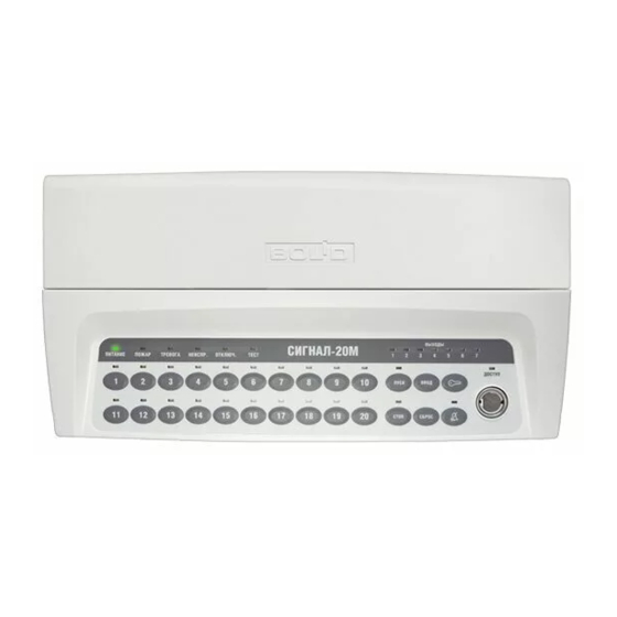
Инструкция по эксплуатации прибора Сигнал-20
Принцип работы прибора:
— Постановка на охрану и снятие с охраны любого ШС (шлейф сигнализации) осуществляется нажатием кнопки данного ШС. Постановка и снятие на охрану любого ШС подтверждается встроенным звуковым сигнализатором и кратковременным включением красного светового сигнала данного шлейфа.
— Если ШС поставлен на охрану, то индикатор под его номером остаётся бесцветным.
— Если ШС не поставлен на охрану, то индикатор остаётся бесцветным
— Если ШС находится в состоянии ПОЖАР, то световой индикатор под определённым ШС светится прерывистым КРАСНЫМ светом
— При работе в режиме пожарной охраны сигнал тревоги выдаётся на звуковой оповещатель после нарушения ШС без задержки
— При извещении НЕИСПРАВНОСТЬ обеспечивается непрерывный звуковой сигнал от прибора.
— В случае ложной сработки поставьте ШС на охрану повторно, для этого нажмите кнопку данного ШС, если ШС не встал на охрану, то снимите его с охраны и пройдите по помещениям, которые контролирует данный шлейф.
Действия персонала при сработке ШС пожарной сигнализации:
- Установить место возгорания. Для этого нужно посмотреть на приборе Сигнал-20 какой из ШС светится КРАСНЫМ светом и свериться с таблицей шлейфов, проверить данные помещения визуально.
- В случае пожара эвакуировать всех людей из помещения
- Вызвать пожарную службу по телефону «01»
- Если очаг возгорания незначительный попытаться устранить его самостоятельно, в случае невозможности устранения пожара своими силами, срочно покинуть помещение и оказать информационную помощь пожарной бригаде
Действия персонала при ложной сработке любого из ШС пожарной сигнализации:
— В случае ложной сработки поставьте ШС на охрану повторно, для этого нажмите кнопку данного ШС, если ШС не встал на охрану, то снимите его с охраны
— Сверившись с таблицей ШС пройти по помещениям, которые контролирует данный шлейф.
— Посмотреть находиться ли один или несколько пожарных датчиков на сработке (световой индикатор на датчике светиться постоянным КРАСНЫМ светом)
— Проверить световой индикатор тревожных кнопок о пожаре (должен светиться прерывистым зелёным светом). Если тревожная кнопка находиться на сработке (индикатор светиться красным светом), то восстановить исходное положение кнопки и поставить шлейф на охрану
Действия персонала в случае «НЕИСПРАВНОСТИ»
— Связаться с обслуживающей Вас компанией и объяснить ситуацию
Телефон: 518-516, 89114234843 Мышев Александр Владимирович
С инструкцией ознакомлены:
_________________________ _________________________
_________________________ _________________________
_________________________ _________________________
_________________________ _________________________
_________________________ _________________________
«____»____________2014 г.