Руководство по эксплуатации автомобиля Skoda Superb 2

Идентификация автомобиля
Идентификационный номер автомобиля (VIN) виден снаружи через специальное окно в нижнем левом углу ветрового стекла (см. иллюстрацию 1а), а при открытом капоте — также на опоре правой стойки подвески (см. иллюстрацию 1b). 1а Номер…

Особенности комплектации автомобиля
В зависимости от исполнения, автомобиль комплектуется компактным запасным колесом, либо набором для ремонта шин. Описание использования набора для ремонта шин приведено в подразделе ниже. В состав бортового набора инструментов…

Использование набора для ремонта шин
Внимание: Герметик из набора для ремонта шин вреден для здоровья, при попадании герметика на кожу немедленно смойте его большим количеством воды. При движении с отремонтированной при помощи набора шиной не превышайте скорость 80…

Вывешивание автомобиля
Замечание: Между опорными точками и подъёмным устройством устанавливайте специальные резиновые кондукторы, охватывающие опорные точки. Опорные точки для подкатного домкрата и лап подъёмника представлены на иллюстрации 7а. 7a…

Транспортировка аварийного автомобиля
Безопаснее всего транспортировать аварийный автомобиль на эвакуаторе. Такая транспортировка может производиться: методом полной погрузки неисправного автомобиля на платформу эвакуатора (предпочтительно); методом частичной…

Запуск двигателя от вспомогательного источника питания
Использование вспомогательного источника питания поможет произвести запуск двигателя в экстремальной ситуации, однако затем следует выяснить и устранить причину разряда батареи. К числу наиболее типичных причин относятся:…

Спецификации автомобиля
Некоторые наружные и внутренние размеры, мм Коэффициент аэродинамического сопротивления (Сх) — 0.3 Наружные размеры, мм Замечание: В зависимости от размера колёс, фактические размеры по высоте, а также ширина колеи могут немного…

Боковые двери и дверь задка/крышка багажного отделения
Описание управления единым замком дверей посредством пульта ДУ, системы «KESSY» и металлического ключа приведено в Разделе 1 . Двигаться с неплотно закрытыми дверьми не допускается. Для предупреждения водителя о незакрытых…

Доступ в подкапотное пространство
Внимание: Прежде чем открывать капот, примите меры против скатывания автомобиля: рычаг селектора DSG установите в положение «Р» а РКПП установите в нейтральное положение, взведите стояночный тормоз, извлеките ключ из замка…

Окна и верхний люк
Окна Внимание. Не препятствуйте закрыванию окон, т.к. это может привести к травме. Замечание. При длительном использовании э/привода стеклоподъёмников он может автоматически отключаться на некоторое время во избежание перегрева….

Противоугонная система
Штатная противоугонная система включает в себя иммобилайзер двигателя и (при соответствующей комплектации) противоугонную сигнализацию. В двери водителя имеется индикатор статуса запирания единого замка ( см. Раздел 1 )….

Ремни безопасности
Общая информация Замечание. Информация об аварийных натяжителях ремней безопасности приведена в Разделе 10 . Всем находящимся в движущемся автомобиле людям следует пристёгиваться ремнями безопасности. Не допускается использование…

Перевозка детей
Для обеспечения безопасности перевозки детей возрастом до 12 лет (ростом до 150 см и весом до 36 кг) следует пользоваться специальными детскими сиденьями и средствами фиксации, сопрягаемыми с ремнями безопасности или креплениями…

Регулировка сидений
Замечание: Не допускается регулировка сидений и рулевой колонки во время движения автомобиля. После регулировки сиденья следует слегка покачаться в нём, чтобы удостовериться в надёжности его фиксации. Сиденья и подголовники —…

Регулировка рулевой колонки
Предусмотрена регулировка рулевой колонки по вылету и по высоте. Рулевую колонку следует отрегулировать таким образом, чтобы рулевое колесо находилось напротив грудной клетки водителя на расстоянии не менее. Положение, при…

Регулировка зеркал заднего вида
Внимание: В зеркалах заднего вида с автоматическим затемнением (в электрохромных зеркалах) содержится жидкий электролит, который при повреждении зеркала может вытечь и вызвать раздражение кожи, глаз и органов дыхания. Прежде…
Системы дополнительной безопасности (SRS)
Внимание: Не располагайте твёрдые или острые предметы между своим телом и подушками безопасности, не перевозите твёрдые или острые предметы на коленях и не курите трубку при управлении автомобилем, т.к. это может привести к…
Опасность отравления монооксидом углерода
В состав отработавших газов (ОГ) двигателя входит в высшей степени токсичный монооксид углерода (СО), который вызывает потерю сознания и может привести к смертельному исходу. При исправной системе выпуска ОГ и правильной…

Левый подрулевой переключатель
12.1 Расположение органов управления 1 Переключатели управления э/приводом стеклоподъёмников ( см. Раздел 5 ) 2 Клавиша единого замка ( см. Раздел 1 ) 3 Боковые дефлекторы климатической системы ( см. Раздел 14 ) 4 Левый…

Органы управления и оборудование автомобиля
Расположение органов управления и оборудования салона на панели приборов, центральной консоли и двери водителя указано на иллюстрации 12.1. Компоненты, для которых в подписях к иллюстрации 12.1 указаны конкретные разделы,…

Правый подрулевой переключатель
Замечание: Во избежание повреждения механизма стеклоочистителей не следует включать их, если очищаемое стекло сухое, а также перемещать их руками. В мороз перед первым за поездку включением стеклоочистителей следует проверить, не…
Выключатель клаксона и переключатели передач
Клаксон работает только при включённом зажигании. Кнопки включения клаксона встроены в накладку рулевого колеса и обозначены соответствующими пиктограммами (около верхних спиц рулевого колеса). Нажимайте на накладку без…
Педали автомобиля
На моделях с РКПП имеется три педали (слева направо): педаль сцепления, педаль тормоза и падаль акселератора («газа»). На моделях с DSG педаль сцепления отсутствует. Управлению и свободному ходу педалей не должны мешать…

Замок зажигания/кнопка «Engine start/stop»
На моделях с системой «KESSY» вместо традиционного замка зажигания установлена кнопка «Engine start/stop». Описание включения/выключения зажигания и пуска двигателя посредством этой кнопки приведено в Разделе 20 . Когда ключ…


Органы управления в центральной консоли
Внимание: Во время движения автомобиля не следует хранить в держателях открытые ёмкости с напитками, особенно горячими, т.к. при маневрировании или торможении напитки могут расплескаться и повредить электрооборудование автомобиля…


Оборудование багажного отделения
Освещение багажного отделения включается после открывания его крышки/ двери задка. Если багажное отделение остаётся открытым, освещение гаснет через 10 минут. На моделях Combi на левой стороне багажного отделения установлен…

Комбинация приборов
Общий вид комбинации приборов и расположение на ней контрольно-измерительных приборов представлены на иллюстрации 13.1. 13.1 Элементы комбинации приборов 1 Тахометр 2 Спидометр 3 Левая кнопка «меню» 4 Указатель температуры ОЖ 5…
Спидометр и тахометр
Спидометр показывает скорость движения автомобиля в км/ч. На моделях для некоторых стран при скорости более 120 км/ч раздаётся предупреждающий звуковой сигнал. Тахометр показывает частоту вращения коленчатого вала двигателя в…
Клавиши комбинации приборов
Замечание: В некоторых вариантах комплектации установить время на часах можно только через меню «Настройки> Время» дисплея комбинации приборов (см. подраздел ниже). Левая и правая клавиши комбинации приборов используются для…

Дисплей в комбинации приборов
Внимание: Не отвлекайтесь на дисплей, если этого не позволяет дорожная обстановка. В комбинации приборов может устанавливаться 240-сегментный или графический (166×110) дисплей. В зависимости от комплектации автомобиля, дисплей…

Контрольные лампы и индикаторы в комбинации приборов
Замечание: В зависимости от комплектации автомобиля, в комбинации приборов одного и того же типа некоторые контрольные лампы могут отсутствовать. Контрольные лампы (К/Л) и индикаторы, кроме индикаторов указателей поворотов,…

Климатическая система
В зависимости от комплектации, автомобиль может быть оборудован либо климатической системой с ручным управлением «Climatic», либо климатической системой с автоматическим управлением «Climatronic». Кроме того может быть установлен…

Автономный отопитель
Автономный отопитель подогревает охлаждающую жидкость двигателя, сжигая топливо из топливного бака. Это позволяет прогреть двигатель и салон, если включён вентилятор климатической системы. Автономный отопитель может работать как…

Аудиосистема и система навигации
Внимание: Не отвлекайтесь на аудиосистему, систему навигации или мобильный телефон, если этого не позволяет дорожная обстановка. В зависимости от комплектации, может быть установлен один из нескольких штатных аудиоблоков….

Мобильный телефон и рация
Держатель для мобильного телефона (устройство handsfree) GSM II Замечание: Описание держателя GSM III во многом совпадает с описанием держателя GSM II и далее не приводится. В некоторых вариантах комплектации установлен держатель…

Темпостат — общие сведения
Внимание: Использование темпостата при напряжённом движении (например, в городе), на скользких и извилистых дорогах, а также в других дорожных ситуациях, которые могут вынудить менять скорость, может привести к потере контроля…

Система помощи при парковке и парковочный автопилот
Внимание: Описанные ниже вспомогательные системы не освобождают водителя от необходимости проявлять внимание во время движения, особенно задним ходом. Некоторые тонкие, расположенные на расстоянии менее 30 см, а также находящиеся…
Система Start-Stop
Внимание: При работах с двигателем выключайте систему Start-Stop во избежание случайного пуска двигателя. Также следует выключать систему Start-Stop при преодолении водных преград. Если система Start-Stop используется в течение…
Система контроля давления накачки шин
Внимание: Система контроля давления накачки шин не отменяет необходимость периодического проведения обычной проверки давления накачки шин. Эта система лишь даёт предупреждение о низком давлении воздуха в шинах, но не накачивает…
Диагностика неисправностей двигателя
Базовые проверки при затруднённом запуске двигателя Бензиновые модели Оцените внешнее состояние всей электропроводки в двигательном отсеке, удостоверьтесь в отсутствии признаков нарушения целостности изоляции, окисления и…
Диагностика неисправностей электрооборудования двигателя
Замечание: Процедуры диагностики электронной системы управления и коды неисправностей приведены в Главе 5 . 17. Имеет место снижение ёмкости или недостаточный заряд батареи 1. Изношен или повреждён приводной ремень генератора,…
Диагностика неисправностей системы питания
21. Чрезмерен расход топлива 1. Загрязнён или заблокирован фильтрующий элемент воздухоочистителя. 2. Недостаточно давление в шинах, либо установлены шины не того размера. 3. Двигатель имеет механические повреждения. Проверьте…
Ссылка на этот раздел в различных форматах
TEXTHTMLBB Code
- Manuals
- Brands
- Skoda Manuals
- Automobile
- 2012 Superb
- Owner’s manual
-
Contents
-
Table of Contents
-
Bookmarks
Related Manuals for Skoda 2012 Superb
Summary of Contents for Skoda 2012 Superb
-
Page 1
SIMPLY CLEVER ŠKODA Superb Owner’s Manual… -
Page 2
Preface You have opted for a ŠKODA – our sincere thanks for your confidence in us. Your new ŠKODA offers you a vehicle featuring the most modern engineering and a wide range of equipment. We recommend that you read this Owner’s Manual carefully so that you can quickly familiarise yourself with your vehicle and all that it has to offer. -
Page 3
The on-board literature The Help on the Road brochure The on-board literature for your vehicle consists of this “Owner’s Manual” as well The Help on the Road brochure contains the most important telephone numbers as a “Service schedule” and the “Help on the road” brochure. in individual countries as well as the addresses and telephone numbers of ŠKODA importers. -
Page 4: Table Of Contents
Windscreen wipers and washers Parking aid Table of Contents Rear window Park assist Cruise control system (CCS) Seats and Stowage Layout of this Owner’s Manual (explanations) START-STOP Front seats Seat heaters Automatic gearbox Abbreviations Ventilated front seats Automatic gearbox Head restraints Communication Using the system Rear seats…
-
Page 5
Changing a wheel Driving Tips Breakdown kit Jump-starting Driving and the Environment Towing the vehicle The first 1 500 kilometres and then afterwards Catalytic converter Fuses and light bulbs Economical and environmentally friendly Fuses driving Bulbs Environmental compatibility Technical data Driving abroad Avoiding damage to your vehicle Technical data… -
Page 6
Table of Contents… -
Page 7: Layout Of This Owner’s Manual (Explanations)
CAUTION Layout of this Owner’s Manual (explanations) A Caution note draws your attention to the possibility of damage to your vehicle (e.g. damage to gearbox), or points out general risks of an accident. The Owner’s Manual has been systematically designed in order to make it easy For the sake of the environment for you to search for and obtain the information you require.
-
Page 8: Abbreviations
Abbreviations Abbreviation Definition Engine revolutions per minute Anti-lock brake system Multi-purpose vehicles Adaptive headlights Automatic gearbox Traction control in g/km discharged quantity of carbon dioxide in grams per driven kilo- meter Diesel particle filter Automatic double clutch gearbox Active driver-steering recommendation Electronic differential lock EPC fault light Stabilisation control…
-
Page 9
Fig. 1 Cockpit Using the system… -
Page 10: Using The System
Regulator for the instrument lighting and regulator for the head- Using the system light beam range adjustment 59, 59 Storage compartment on the driver’s side Lever for adjusting the steering wheel Cockpit Driver’s knee airbag Ignition lock TCS switch Overview Tyre pressure monitoring system Depending on equipment fitted: Power windows…
-
Page 11: Instruments And Warning Lights
Overview of the Instrument cluster Instruments and warning lights Instrument cluster ä Introduction This chapter contains information on the following subjects: Overview of the Instrument cluster Engine revolutions counter Speedometer Coolant temperature gauge Fuel gauge Counter for distance driven Service Interval Display Fig.
-
Page 12: Engine Revolutions Counter
Fuel gauge » page 12 Coolant temperature gauge Button for: › Reset trip counter for the distance driven ä First read and observe the introductory information and safety warn- › Resetting Service Interval Display ings on page 10. › Set hours/minutes ›…
-
Page 13: Fuel Gauge
Daily trip counter (trip) Fuel gauge The daily trip counter indicates the distance which you have driven since it was last reset — in steps of 100 metres or 1/10 of a mile. ä First read and observe the introductory information and safety warn- ings on page 10.
-
Page 14: Digital Clock
The kilometre indicator or the days indicator reduces in steps of 100 km or, where Note applicable, days until the service due date is reached. Never reset the display between service intervals, as this will result in the incor- ■ As soon as the due date for the service is reached, a flashing key symbol …
-
Page 15: Multi-Functional Indicator (Onboard Computer)
Recommended gear Display in rear centre console Fig. 4 Fig. 5 Recommended gear Centre console at rear: Display ä ä First read and observe the introductory information and safety warn- First read and observe the introductory information and safety warn- ings on page 10.
-
Page 16: Warning
The multi-functional indicator can only be operated when the ignition is switched The multi-functional indicator is equipped with two automatic memories. The se- on. After the ignition is switched on, the function displayed is the one which you lected memory is shown in the Display »…
-
Page 17: Operation
The following readouts of the selected memory will be set to zero with the but- Operation on the windshield wiper lever or with the button on the multifunction steering wheel: › average fuel consumption, › distance driven, › average speed, ›…
-
Page 18: Current Fuel Consumption
The estimated range in kilometres is shown on the display. It indicates the dis- Current fuel consumption tance you can still drive with your vehicle based on the present level of fuel in the tank for the same style of driving. ä…
-
Page 19: Maxi Dot (Information Display)
A zero appears in the display for the first approx. 300 m you drive after erasing This allows you to set the speed in 5 km/h intervals. the memory. Adjust the speed limit while the vehicle is moving › The indicated value will be regularly updated while you are driving. …
-
Page 20
The information display provides you with information in a convenient way con- Main menu cerning the current operating state of your vehicle. The information system also provides you with data (depending on the equipment installed in the vehicle) re- lating to the radio, mobile phone, multi-functional indicator, navigation system, the unit connected to the MDI input and the automatic gearbox. -
Page 21
Vehicle status » page 21 Factory setting ■ ■ Back ■ Settings » page 20 ■ After selecting the menu point Back you will reach one level higher in the menu. The menu points Audio and Navigation are only displayed when the factory-fitted radio or navigation system is switched on. -
Page 22: Auto Check Control
Service Coming Home Switch on/off and adjust the light duration of the Com- Here you can have the remaining kilometres and days until the next service inter- ing Home function. val displayed, and reset the Service Interval Display. Leaving Home Switch on/off and adjust the light duration of the Com- ing Home function.
-
Page 23: Warning Lights
There is at least one error message when the term Vehicle status is displayed in Check engine oil level, » page 26 the menu. After selecting this menu the first of the error messages is displayed. engine oil sensor faulty Several error messages are shown on the display under the message e.g.
-
Page 24
Adaptive headlights » page 24 Boot lid » page 30 Diesel particle filter (diesel engine) » page 24 Open door » page 30 Airbag system » page 25 Windscreen washer fluid level » page 30 … -
Page 25
If a turn signal light fails, the indicator light flashes at twice its normal rate. This Adaptive headlights does not apply when towing a trailer. Switching off the hazard warning light system is switched on will cause all of the If the indicator light flashes for 1 minute and a warning signal sounds while … -
Page 26
The following text will be displayed in the information display: WARNING Airbag/belt tensioner deactivated! The diesel particle filter achieves very high temperatures. Therefore do not ■ The following applies if the airbag has been switched off using the key switch park in areas where the hot filter can come into direct contact with dry grass in the storage compartment: or other combustible materials — risk of fire! -
Page 27
Steering lock (KESSY system) Do not continue your journey if for some reason it is not possible to top up the › While the warning light is flashing, the steering lock cannot be released. engine oil under the prevailing conditions. Keep the engine switched off and … -
Page 28
The indicator light flashes Coolant temperature/coolant level A fault on the engine oil level sensor is indicated additionally by an audible signal and the warning light coming on several times after the ignition has been switch- The warning light comes on for a few seconds when the ignition is switched … -
Page 29
The ESC cannot be switched off with the button » Fig. 117; only the ASR system Traction control system (ASR) is switched off and the indicator light in the instrument cluster lights up. The warning light comes on for a few seconds when the ignition is switched The indicator light illuminates permanently if there is a fault in the ESC. -
Page 30
Note WARNING If the battery has been disconnected, the indicator light illuminates after the If you have to stop for technical reasons, then park the vehicle at a safe dis- ■ ignition is switched on. The warning light must go out after driving a short dis- tance from the traffic, switch off the engine and activate the hazard warning tance. -
Page 31
If the seat belt is not fastened by the driver or front passenger during the next In vehicles with an information display, this indicator light is replaced by a vehicle 90 seconds, the warning signal is deactivated and the indicator light lights up symbol »… -
Page 32
WARNING CAUTION If you have to stop for technical reasons, then park the vehicle at a safe dis- If the indicator light (cooling system fault) comes on in addition to the indicator ■ tance from the traffic, switch off the engine and activate the hazard warning light on the display when driving, stop immediately and switch the engine off — … -
Page 33: Unlocking And Locking
Note Unlocking and locking Please approach a ŠKODA Service Partner if you lose a key as they can obtain a new one for you. Vehicle key Replacing the battery in the remote control key Introductory information Fig. 9 Remote control key Fig.
-
Page 34: Child Safety Lock
For the sake of the environment Central locking system Dispose of the used battery in accordance with national legal provisions. Introductory information Note When using the central locking and unlocking system, all the doors and the fuel The system has to be synchronised, if the vehicle cannot be unlocked or locked filler flap are locked or unlocked at the same time (if it was not set differently in with the remote control key after replacing the battery »…
-
Page 35: Safe Securing System
Unlocking the vehicle with the KESSY system gins to flash evenly at longer intervals. It is not possible to open the doors with This selection function enables to unlock all the doors, individual doors, both the door handle either from the inside or from the outside. This acts as an effec- doors on the left and right vehicle side or to unlock the driver and front passenger tive deterrent for attempts to break into your vehicle.
-
Page 36: Remote Control
WARNING Central locking button The central locking system also operates if the ignition is switched off. Chil- Fig. 12 dren should never be left unattended in the vehicle since it is difficult to pro- vide assistance from the outside when the doors are locked. Locked doors Central locking system make it difficult for rescuers to get into the vehicle in an emergency — hazard! Note…
-
Page 37
The battery must be replaced if the central locking or anti-theft alarm system Folding out the key bit ■ › does react to the remote control at less than 3 metres away » page Press the button If the driver door is open, the vehicle cannot be locked using the remote control ■… -
Page 38: Anti-Theft Alarm System
When is the alarm triggered? Synchronising the remote control The following security areas of the locked vehicle are monitored: › If the vehicle cannot be unlocked by actuating the remote control system then it Bonnet, › is possible that the code in the key and the control unit in the vehicle are no lon- Boot lid, ›…
-
Page 39: Kessy System
The interior monitor detects movements inside the car and then triggers the Unlocking and locking car alarm. Switch off the interior monitor and towing protection monitoring › Switch off the ignition. › Open the driver door. › Press the button on the centre column on the driver side »…
-
Page 40
› Close the boot lid and it is locked. Messages in the instrument cluster display Check locking The following messages can be displayed in the information display or display of After locking the vehicle by means of the sensor » Fig. 15, it is not possible to the instrument cluster: unlock the vehicle using the sensor… -
Page 41: Emergency Unlocking And Locking Of The Driver’s Door
Emergency locking of the doors Convenience operation of windows If you hold your finger on the sensor » Fig. 15 for more than 2 seconds while Fig. 17 locking the vehicle, the opened windows and the panoramic sliding roof are Rear door: Emergency locking of closed.
-
Page 42
There is a risk of unwanted entry into the vehicle before the boot lid is locked au- WARNING tomatically. The vehicle should therefore always be locked with the button the radio remote control. Ensure that the lock is properly engaged after closing the boot lid. Other- … -
Page 43
Twindoor — large boot lid Boot lid (Combi) Fig. 20 Handle of boot lid ä First read and observe the introductory information and safety warn- Fig. 19 Handle of boot lid/opened large boot lid ings on page 40. ä First read and observe the introductory information and safety warn- The boot lid can be opened by pressing the handle above the licence plate after ings on page 40. -
Page 44
Emergency unlocking of the boot lid Fig. 21 Emergency unlocking of the boot lid ä First read and observe the introductory information and safety warn- ings on page 40. The boot lid can be unlocked manually if there is a fault in the central locking sys- tem. -
Page 45: Electric Boot Lid (Combi)
CAUTION Electric boot lid (Combi) In a critical situation, the movement of the lid can be stopped by applying an ■ Introductory information abrupt and quick force against the lid. Before opening or closing the lid, check if there are any objects in the opening ■…
-
Page 46
Operation of the boot lid using the handle Description of the operation Area Closed Open Action Fig. 24 Opening Designation of the areas Stop Closing The operation of the boot lid, using the handle is only possible when the vehi- cle is unlocked… -
Page 47: Electric Power Windows
Examples of operational malfunctions Setting the top position of the lid Description of the malfunc- Possible solutions tion If the space for opening the lid is restricted (e.g. height of garage) or for more convenient operation (e.g. according to a person’s height), it is possible to set the The lid cannot be lifted out of Emergency unlocking of the lid »…
-
Page 48: Fig. 25
WARNING Buttons on the driver’s door If the vehicle is locked from the outside, do not leave anybody in the vehicle ■ as it is not possible to open the windows from the inside in the event of an Fig. 25 emergency.
-
Page 49: Window Convenience Operation
Safety pushbutton Force limiter of the power windows The buttons for power windows in the rear doors can be deactivated by pressing the safety pushbutton » Fig. 25. The buttons for the power windows in rear ä First read and observe the introductory information and safety warn- doors are activated again by pressing the safety pushbutton again.
-
Page 50: Electric Sliding/Tilting Roof
You can interrupt the opening or closing process for the windows immediately by The sliding/tilting roof is operated by means of the control dial » Fig. 27 and only releasing the key or the lock button. functions when the ignition is switched on. The control dial has several positions. …
-
Page 51
Safety closing Emergency operation The sliding/tilting roof is fitted with a force limiter. If an obstacle (e.g. ice) pre- vents closing, the sliding/tilting roof stops and opens completely. The sliding/tilt- ing roof can be closed completely without the force limiter by turning the switch into position »… -
Page 52: Panoramic Sliding Roof (Combi)
Force limiter Panoramic sliding roof (Combi) The panoramic sliding roof is fitted with a force limiter. The panoramic sliding roof stops and moves back several centimetres when it cannot be closed because there is something in the way (e.g. ice). The panoramic sliding roof can be fully Introductory information closed without a force limiter by pressing the switch on the recess down and then pushing it forward until the panoramic sliding roof is fully closed…
-
Page 53
Closing Emergency operation › Briefly press the button » Fig. 30 to close fully. › Press and hold the button to close in the desired position. The closing proc- ess stops when one releases the button. Convenience operation The panoramic sliding roof and the sun screen can also be operated from the out- side using the remote control key or when using the KESSY system with the aid of the sensor »… -
Page 54
Press and hold the switch » Fig. 30 for approx. 10 seconds to initialise the sun screen. If the panoramic sliding roof or sun screen is not fully closed when disconnecting and reconnecting the battery, they must first be closed or pushed shut »… -
Page 55: Lights And Visibility
WARNING Lights and Visibility Never drive with only the parking light on! The side lights are not bright ■ enough to light up the road sufficiently in front of you or to be seen by other Lights oncoming traffic. Therefore always switch on the low beam when it is dark or if visibility is poor.
-
Page 56: Switching Lights On And Off
Activating the function daylight driving lights Switching lights on and off › Pull the turn signal light lever towards the steering wheel within 3 seconds of switching on the ignition and at the same time, slide it upwards and hold it in this position for at least 3 seconds.
-
Page 57: Parking Light
If the light comes on automatically, the side lights and low beam as well as li- COMING HOME/LEAVING HOME function cence plate light light up at the same time. ä If the automatic driving lamp control is switched on, the light is regulated with First read and observe the introductory information and safety warn- the light sensor in the rear mirror holder.
-
Page 58: Adaptive Headlights (Ahl)
Mode city Note In the mode “city”, the dispersion of the cone of light in front of the vehicle is wid- er and the width of illumination is shorter. The aim is to illuminate the adjacent If the COMING HOME/LEAVING HOME function is switched on constantly, the ■…
-
Page 59: Fog Lights
› the fog lights are not switched on; Fog lights › no reverse gear is engaged. Note Fig. 34 Dash panel: Light switch If the reverse gear is engaged during the active function CORNER, both fog lights illuminate. Rear fog lights ä…
-
Page 60: Instrument Lighting
Settings Instrument lighting The positions correspond approximately to the following vehicle loads: Front seats occupied, luggage compartment empty. Fig. 35 All seats occupied, luggage compartment empty. Dash panel: Instrument lighting All seats occupied, luggage compartment laden. Driver seat occupied, luggage compartment laden. CAUTION Always adjust the headlight range adjustment in such a way that: it does not dazzle other road users, especially oncoming traffic,…
-
Page 61: Interior Light
› All the turn signal lights on the vehicle flash at the same time when the hazard Push the lever away from the steering wheel in the direction of arrow warning light system is switched on. The indicator light for the turn signals and (spring-tensioned position).
-
Page 62
Switching the interior light on Front reading lights › Press the switch in the area of the symbol » Fig. Switching the interior light off › Press the switch in the area of the symbol O. Operating the light with the door contact switch ›… -
Page 63: Entry Lighting
Reading lights The warning light goes on every time the door is opened. The light goes out › Press switch » Fig. 41 to switch the reading lights on or off. about 10 minutes after opening the door in order to avoid discharging the battery …
-
Page 64: Luggage Compartment Light (Combi)
Reinserting the lamp the holder Luggage compartment light (Combi) › First of all place the deactivated lamp in the holder on the side facing the boot lid and then press on the lamp from the other side until it is clicks into place. Removable lamp Operation of the lamp ›…
-
Page 65: Visibility
The windshield and rear window heater automatically switches off after 10 mi- For the sake of the environment nutes. Dispose of the faulty rechargeable batteries in accordance with environmental For the sake of the environment regulations. The heating should be switched off as soon as the window is de-iced or free from Note mist.
-
Page 66: Windscreen Wipers And Washers
WARNING Sun screen in the rear doors The sun visors must not be swivelled towards the side windows in the deploy- ment area of the head airbags if any objects, such as ball-point pens, etc. are Fig. 48 attached to them. This might result in injuries to the occupants if the head air- Rear door: Sun screen bag is deployed.
-
Page 67: Activating The Windshield Wipers And Washers
The rain sensor automatically regulates the break between the individual wiper Note strokes depending on the intensity of the rain. If the slower » Fig. 49 or the faster wiper setting is switched on and the ■ The rear window is wiped once if the windshield wipers are on when reverse gear vehicle speed decreases to below 4 km/h, the lower wiper step is switched on au- is selected.
-
Page 68: Automatic Rear Window Wiper (Combi)
› Set the desired break between the individual wiper strokes with the switch This rest position is set as follows: › Switch on the windshield wipers. Slow wipe › Switch off the ignition. The windscreen wipers remain in the position in which ›…
-
Page 69: Headlight Cleaning System
Service position for changing wiper blades Headlight cleaning system › Closing the bonnet. › Switch the ignition off and on again. ä First read and observe the introductory information and safety warn- › Then press the windshield wiper lever into position »…
-
Page 70: Rear Window
Replacing the rear window wiper blade (Combi) Automatic dimming interior mirror Fig. 51 Fig. 52 Rear window wiper blade Automatic dimming interior mir- ä First read and observe the introductory information and safety warn- Switching on automatic dimming › ings on page 65.
-
Page 71: Exterior Mirror
Folding-in both of the exterior mirrors using the remote control key Exterior mirror › If all of the windows are closed, press and hold the lock button » Fig. 13 the radio remote control for approx. 2 seconds. Fig. 53 The exterior mirrors are folded back into the driving position after opening the Inner part of door: Rotary knob door or switching on the ignition.
-
Page 72: Exterior Mirror With Entry Lighting
Do not touch the surface of the exterior mirrors if the exterior mirror heater is ■ switched on. If the power setting function fails at any time, the exterior mirrors can be set by ■ hand by pressing on the edge of the mirror surface. Contact your specialist garage if there is a fault with the power setting of the ■…
-
Page 73: Seats And Stowage
WARNING (Continued) Seats and Stowage Each occupant must correctly fasten the seat belt belonging to the seat. ■ Children must be fastened » page 162, Transporting children safely with a Front seats suitable restraint system. The front seats and the head restraints must always be adjusted to match ■…
-
Page 74
Manually adjusting the front seats Adjusting front seats electrically Fig. 54 Control elements at the seat ä First read and observe the introductory information and safety warn- Fig. 55 Controls for the electric seat adjustment ings on page 72. ä First read and observe the introductory information and safety warn- Adjusting a seat in a forward/back direction ings… -
Page 75
Note Storing setting For safety reasons, it is not possible to store this position if the inclination angle ■ Fig. 56 of the seat backrest is more than 102° in relation to the seat cushion. Each new setting stored with the same button erases the previous setting. Memory buttons and SET button ■… -
Page 76: Seat Heaters
Seat heaters Retrieving the seat and exterior mirror settings ä First read and observe the introductory information and safety warn- ings on page 72. Retrieving settings via the memory button › One-touch automatic memory: briefly press the desired memory button »…
-
Page 77: Ventilated Front Seats
› To switch off the ventilation shift the rocker switch into the horizontal position CAUTION . Do not kneel on the seats or otherwise apply pressure at specific points to ■ WARNING avoid damaging the heating elements for the seat heaters. Do not use the seat heaters if the seats are not occupied by persons or if ob- ■…
-
Page 78
› The head restraints must be adjusted to match the size of the seat occupant. Cor- To re-insert the head restraint, push it far enough down into the seat backrest rectly adjusted head restraints together with the seat belts offer effective protec- until the locking button clicks into place. -
Page 79: Rear Seats
WARNING Rear seats The belts and the belt locks must be in their original position after folding ■ Folding the seat backrest forwards back the seat backrests — they must be ready to use. The seat backrests must be securely interlocked in position so that no ob- ■…
-
Page 80: Luggage Compartment
In the event of an accident, there is such a high kinetic energy which is produced Rear armrest by small and light objects that they can cause severe injuries. The magnitude of the kinetic energy is dependent on the speed at which the vehicle is travelling and the weight of the object.
-
Page 81: Class N1 Vehicles
WARNING (Continued) Fastening elements Under no circumstances, should the permissible axle loads and permissible ■ gross weight of the vehicle be exceeded — risk of accident! Never transport people in the boot! ■ CAUTION Make sure that transported objects with sharp edges do not damage the follow- ing: heating elements in the rear window, ■…
-
Page 82: Folding Hooks
Fixing examples for a fixing net as a vertical pocket » Fig. 66 — , floor fixing net Folding hooks and horizontal pocket » Fig. 66 — . WARNING The permissible load of the side nets is 1.5 kg. Heavy objects are not secured sufficiently — risk of injury and net damage! CAUTION Do not place any sharp objects in the nets — risk of damaging the net.
-
Page 83: Luggage Net
ä First read and observe the introductory information and safety warn- Luggage net ings on page 79. The luggage compartment cover can be removed if you wish to transport bulky Fig. 68 goods. Luggage compartment: Luggage › Unhook the support straps »…
-
Page 84: Variable Loading Floor In The Luggage Compartment
Foldable luggage compartment cover (Combi) Automatic foldable luggage compartment cover (Combi) The automatic rolling up of the foldable luggage compartment cover enables an easier entry into the luggage compartment. ä First read and observe the introductory information and safety warn- ings on page 79.
-
Page 85: Extendable Variable Loading Floor With Integrated Aluminium Strips And Fastening Elements (Combi)
WARNING Dividing the luggage compartment with variable loading floor Ensure that the carrier rails and variable loading floor are correctly fastened Fig. 71 when installing the variable loading floor. If this is not the case, there is a risk of injury for the occupants. Luggage compartment: Dividing …
-
Page 86
The variable loading floor can be partially pulled out over the rear bumper. The Removing and installing the variable loading floor variable loading floor which is pulled out in such a way is solely used as a seat, for example for changing shoes. When pulling out the variable loading floor, the front edge (close to the rear seats) is lifted at the same time. -
Page 87: Net Partition (Combi)
› Carefully press in the vicinity of the openings on the floor until it clicks into WARNING place, if necessary press the safety buttons The objects in the luggage compartment must be firmly secured with the fix- WARNING ing set so that they cannot move freely and uncontrollably and to prevent damage to objects or injuries to occupants.
-
Page 88
If you wish to use the entire luggage compartment, the foldable luggage com- WARNING partment cover can be removed » Fig. The belt locks and the belts must be in their original position after folding ■ back the seat cushions and backrests — they must be ready to use. Using the net partition behind the front seats The seat backrests must be securely interlocked in position so that no ob- ■… -
Page 89: Roof Luggage Rack
WARNING Removing and installing net partition housing The items which you transport on the roof bar system must be reliably at- ■ Fig. 81 tached — risk of accident! Always secure the load with appropriate and undamaged lashing straps or Rear seats: Net partition hous- ■…
-
Page 90: Cup Holder
Cup holder Attachment points ä Introduction Fig. 82 Attachment points for roof bars This chapter contains information on the following subjects: Cup holder in front centre console Cup holder in the rear armrest WARNING Never put hot beverage containers in the cup holder. If the vehicle moves, ■…
-
Page 91: Ashtray
On vehicles that are fitted with a cover for cup holders, you can cover the cup Ashtray holder by pulling on the handle Front ashtray Cup holder in the rear armrest Fig. 85 Centre console: Front ashtray Removing ashtray insert ›…
-
Page 92: Cigarette Lighter, 12-Volt Power Socket
Removing ashtray insert 12-volt power socket › Open the ashtray » Fig. › Grasp the insert in the area marked with the arrows » Fig. 86 and remove it. Insert ashtray insert › Place the ashtray insert in the mount and press it in. WARNING Never place flammable objects in the ashtray — risk of fire! …
-
Page 93: Storage Compartments
Side compartments in the luggage compartment » page 97 CAUTION Lockable side compartment (Combi) » page 97 Never exceed the maximum power consumption, otherwise the vehicle’s elec- ■ Non-lockable side compartment (Combi) » page 97 trical system can be damaged. Connecting electrical components when the engine is not running will drain the ■…
-
Page 94
Cooling the storage compartment on the front passenger side Stowage compartment in front centre console Fig. 89 Fig. 91 Storage compartment: Using Front centre console: Stowage cooling system compartment › › Open the air supply by pulling the lever in the direction of the arrow »… -
Page 95
CAUTION WARNING No objects with sharp edges should be stored in the storage net, as they can Only use the storage compartments in the door panels » Fig. 94 for smaller damage the storage net. items that do not project out of the compartment so that the deployment … -
Page 96
Opening storage compartment Stowage compartment in rear centre console › Open the lid of the armrest in the direction of the arrow » Fig. Closing storage compartment Fig. 98 › Open the lid to the stop, only then can it be folded downwards. Centre console at rear: Stowage compartment Setting height… -
Page 97: Through-Loading Bag
Seat backrest with through-loading channel Through-loading bag The removable through-loading bag is solely used for transporting skis. Fig. 101 Securing the through-loading Fig. 100 Rear seats: Cover handle/luggage compartment: Unlock button Loading After folding the rear armrest and cover up, an opening in the seat backrest be- ›…
-
Page 98
The first-aid box can also be stored in this compartment. WARNING After placing skis into the through-loading bag, you must secure the bag ■ Lockable side compartment (Combi) with the securing strap The strap must hold the skis tight. ■… -
Page 99: Clothes Hooks
CAUTION WARNING Ensure that the side compartment cover and the mount for the cover are not The attached note has to always be removed before starting off in order not damaged during installation or removal. to restrict the driver’s vision. …
-
Page 100: The Air Conditioning System
Note The air conditioning system The used air streams out through the air removal openings in the luggage com- ■ partment. Introductory information We recommend that you do not smoke in the vehicle when the recirculating air ■ mode is operating since the smoke which is drawn at the evaporator from the in- terior of the vehicle forms deposits in the evaporator of the air conditioning sys- Description and information tem.
-
Page 101: Air Outlet Vents
If you cannot rectify the functional fault yourself, or the cooling capacity decrea- Close air outlet vents › ses, the cooling system must be switched off. Visit a specialist garage. Turn the rotary knob into the position 0. Changing the air flow direction ›…
-
Page 102
Note Using the system The whole heat output will be needed to defrost the windshield and side win- ■ dows. No warm air will be fed to the footwell. This can lead to restriction of the heating comfort. The warning light in the button lights after activation, even if not all of the ■… -
Page 103
Setting the air conditioning system Recommended basic settings of the control elements of the air conditioning sys- tem for the respective operating modes: Setting of the control dial Button Set-up Air outlet vents 2 Defrost windscreen and side Desired tempera- Automatically Open and align with the side … -
Page 104: Climatronic (Automatic Air Conditioning System)
Note Climatronic (automatic air conditioning system) We recommend that you have Climatronic cleaned by a specialist garage once ■ Description every year. On vehicles equipped with a factory-fitted radio or radio navigation system, the ■ The Climatronic maintains fully automatically a convenience temperature. This is Climatronic information is also shown on their displays.
-
Page 105: Setting Temperature
Setting the blower speed Switching the cooling system on and off Depending upon vehicle equipment: Button for directly switching on/off the auxiliary heating » page 105 or switching on/off the windshield heater Switching the cooling system on and off ›…
-
Page 106: Auxiliary Heating (Auxiliary Heating And Ventilation)
› control is automatically switched off so that fresh air can be guided into the vehi- Repeatedly press the button on the left side (reduce blower speed) or on cle interior. In recirculated air mode air is sucked out of the interior of the vehicle the right side (increase blower speed).
-
Page 107
Auxiliary heating (parking heating) The auxiliary heating only switches the blower on, if it has achieved a coolant ■ The auxiliary heating (auxiliary heating) functions in connection with the air-con- temperature of approx. 50 °C. ditioning system or Climatronic. At low outside temperatures, this can result in a formation of water vapour in ■… -
Page 108: System Settings
If the auxiliary heating and ventilation is not switched off earlier, it switches off Factory setting automatically after the set operating period, in the menu Running time has ex- Recreate the factory settings. pired. Back Selecting the menu point Back, takes you back to the menu Aux. heating. System settings Only one programmed pre-set time can be active.
-
Page 109
If the battery is properly charged, the effective range is up to 600 m. To switch Changing the battery of the radio remote control on/off the auxiliary heating, hold the radio remote control vertically with the an- tenna » Fig. 111 facing upwards. -
Page 110: Starting-Off And Driving
WARNING (Continued) Starting-off and Driving When driving, the ignition key must always be in the position (ignition ■ switched on) without the engine running. This position is indicated by the Starting and stopping the engine warning lights coming on. If this is not the case, it could result in unexpected locking of the steering wheel — risk of accident! Only pull the ignition key from the ignition lock when the vehicle has come ■…
-
Page 111: Electromechanical Power Steering
› First of all adjust the driver’s seat » page For the sake of the environment › Pull the lever below the steering wheel down » Fig. 112 — . › Adjust the steering wheel to the desired position (with regard to the height and Do not warm up the engine while the vehicle is stationary.
-
Page 112: Ignition Lock
Vehicles with a diesel engine are equipped with a glow plug system. The pre- Ignition lock glow indicator light comes on after the ignition has been switched on. The en- gine should be started immediately after the preglow indicator light goes out. Fig.
-
Page 113: Kessy System
KESSY system Unlocking and locking the steering ä Introduction Fig. 114 Starter button This chapter contains information on the following subjects: Unlocking and locking the steering Switching on the ignition Switching off the ignition Emergency ignition shutoff system Starting engine Emergency start-up of engine ä…
-
Page 114: Switching On The Ignition
Maintain the clutch pedal depressed when starting vehicles fitted with a manual Switching on the ignition gearbox. On vehicles with an automatic gearbox, place the selector lever in posi- tion P or N and depress the brake pedal until the engine starts. ä…
-
Page 115: Brakes And Brake Assist Systems
Brakes and brake assist systems Emergency start-up of engine ä Introduction Fig. 115 Emergency start-up of engine This chapter contains information on the following subjects: Information on braking Handbrake Stabilisation Control (ESC) Antilock brake system (ABS) Traction control system (ASR) Electronic differential lock (EDL) ä…
-
Page 116: Information On Braking
Wet roads or road salt CAUTION The performance of the brakes can be delayed as the brake discs and brake pads may be moist or have a coating of ice or layer of salt on them in winter. The Observe the information on the new brake pads »…
-
Page 117
Releasing the handbrake The ESC cannot be switched off, the button » Fig. 117 only deactivates the ASR › Pull the handbrake lever up slightly and at the same time push in the locking system and the indicator light in the instrument cluster lights up. -
Page 118: Electronic Differential Lock (Edl)
The uphill start assist is active as of a 5 % slope, if the driver door is closed. It is The TCS should normally always be switched on. It may be advisable to switch off always active on slopes when in forward or reverse start off. When driving down- the system in certain exceptional circumstances, such as: ›…
-
Page 119: Shifting (Manual Gearbox)
Only use footmats from the range of ŠKODA Original Accessories, which are fitted Shifting (manual gearbox) to two attachment points. WARNING Fig. 119 The shift pattern: 5-speed or 6- No objects are allowed in the driver’s footwell – risk of obstruction or limita- ■…
-
Page 120: Park Assist
On vehicles with a factory-fitted towing device, the border of the danger area Note starts (continuous tone) 5 cm further away from the vehicle. The length of the ve- hicle can be increased with an installed detachable towing device. If a warning signal sounds for about 3 seconds after activating the system and ■…
-
Page 121
WARNING Park assist display on the information display The park assist does not take away the responsibility from the driver when ■ parking. External sound sources can have a detrimental effect on the park assist sys- ■ tem and parking aid. Under unfavourable conditions, objects or people may not be recognised. -
Page 122
› As soon as the following message is shown in the information display: Steering Parking with the help of the park assist system and intervent. active. Check area around veh.! , let go of the steering wheel and the completing the parking procedure steering is taken over by the system. -
Page 123: Cruise Control System (Ccs)
Park Assist: Speed too high. ASR intervention! Please take over steering! Reduce the speed to below 30 km/h. The parking procedure is terminated by the intervention of the ASR. Driver steering intervention: Please take over steering! Park Assist: Stationary time not sufficient. The parking procedure is terminated due to driver intervention.
-
Page 124
CAUTION Changing a stored speed Always depress the clutch pedal if switching to the neutral position (vehicle ■ ä First read and observe the introductory information and safety warn- with a manual gearbox) when the cruise control system is switched on! Otherwise ings on page 122. -
Page 125: Start-Stop
Briefly press the rocker button into the position RES to resume the stored Switching the START-STOP system on and off speed after the clutch or brake pedal is released. The START-STOP system can be switched on/off by pressing the but- …
-
Page 126
Conditions for an automatic restart without driver intervention Note › The vehicle moves at a speed of more than 3 km/h. › The difference between the outdoor- and the set temperature in the interior is Changes to the outdoor temperature can have an effect on the internal temper- ■… -
Page 127: Automatic Gearbox
WARNING (Continued) Automatic gearbox If stopping on a hill (downhill gradient), never try to maintain the vehicle sta- ■ tionary with the gear engaged by means of the “accelerator pedal”, i.e. by let- Automatic gearbox ting the clutch slip. This can lead to overheating of the clutch. If there is a risk of overheating of the clutch due to overload, the clutch is opened automati- cally and the vehicle rolls backward — risk of accident! ä…
-
Page 128: Starting-Off And Driving
When parking on a level road surface, it suffices to engage selector lever position Selector lever positions P. When parking on a slope, the handbrake should be applied firmly before the park position is selected. This ensures that there is no excessive pressure on the lock mechanism and that it is subsequently easier to move the selector lever out of position P.
-
Page 129: Manual Shifting Of Gears (Tiptronic)
ä — Neutral First read and observe the introductory information and safety warn- The transmission is in Neutral in this position. ings on page 126. The brake pedal must be depressed to move the selector lever out of the position Tiptronic mode makes it possible to manually shift gears on the selector lever and N (if the lever is in this position for longer than 2 seconds) into the position D or R multifunction steering wheel.
-
Page 130: Selector Lever Lock
eral gears in line with the driving state and the vehicle accelerates. The gearbox Selector lever lock does not shift up into the highest gear until the engine has reached its maximum revolutions for this gear range. ä First read and observe the introductory information and safety warn- ings on page 126.
-
Page 131: Emergency Programme
› Firmly apply the handbrake. Emergency programme › Grasp the selector lever cover in the area of arrow » Fig. 128 and carefully pull upwards. ä First read and observe the introductory information and safety warn- › Also unlock the cover on the other side. ings on page 126.
-
Page 132
Automatic gearbox… -
Page 133: Communication
WARNING (Continued) Communication If a mobile phone or a two-way radio system is operated in a vehicle without ■ an external aerial or an external aerial which has been installed incorrectly, Mobile phones and two-way radio systems this can increase the strength of the electromagnetic field inside the vehicle. Two-way radio systems, mobile phones or mounts must not be installed on ■…
-
Page 134: Operating The Phone On The Multifunction Steering Wheel
Operating the phone on the multifunction steering wheel The driver can set the basic functions of the telephone by simply operating the buttons located on the steering wheel so that he can concentrate on the traffic situation without being distracted as little as possible by operating the tele- phone »…
-
Page 135: Symbols In The Information Display
Symbols in the information display Symbol Importance Valid for Charge status of the phone battery GSM II, GSM III Signal strength GSM II, GSM III a phone is connected to the hands-free system. GSM II, GSM III when connected via the HFP profile …
-
Page 136
› Voice control of the telephone » page 141. Up to four mobile phones can be paired with the hands-free system, whereby on- › Music playback from the telephone or other multimedia units » page 143. ly one mobile phone can communicate with the hands-free system. All communication between a mobile phone and your vehicle’s hands-free system The visibility of the hands-free system is automatically switched off 3 minutes af- ®… -
Page 137
Note CAUTION If a suitable adapter is available for your mobile phone, only use your mobile Taking the mobile phone out of the adapter during the call can lead to interrup- ■ phone in the adapter inserted in the telephone mount so that the radiation in the tion of the connection. -
Page 138: Universal Telephone Preinstallation Gsm Iil
Search ■ Phone book ■ Phone name — the possibility to change the name of the telephone unit (pre-set ■ ■ Dial number SKODA UHV) Call register ■ Settings Voice mailbox ■ ■ Bluetooth The following menu points can be selected in the menu Settings: Settings ■…
-
Page 139
› All communication between a telephone and the hands-free system of your vehi- If your SIM card is blocked by a PIN code, enter the PIN code for the SIM card in ® cle can only be established with the help of the following profiles of Bluetooth your phone. -
Page 140
Dial number Note Any telephone number can be written in the menu point Dial number. The re- quired numbers must be selected one after the other using adjustment wheel In the memory of the control unit, up to three users can be stored, whereby the ■… -
Page 141: Internet Connection
Phone name — the possibility to change the name of the hands-free system Data — Settings for the Internet access point — ask network operator for details ■ ■ (pre-set SKODA UHV) Switch off ph. (Switch off ph.) — switches off the phone unit (phone remains ■ coupled)
-
Page 142: Voice Control
› ® Use the device that is to be connected to search for available Bluetooth devi- The digits 0 — 9, symbols +, , # are permitted. The system detects no continuous ces. digit combinations such as twenty-three, but only individually spoken digits (two, ›…
-
Page 143
Voice commands — GSM II Voice commands — GSM III Basic voice commands Basic voice commands Voice command Action Voice command Action After this command the system repeats all possible After this command the system repeats all possible HELP HELP commands. -
Page 144: Multimedia
The music playback process is performed on the connected device. Multimedia The universal telephone preinstallation GSM II ensures that the music played back via the hands-free system can be controlled with the remote control » page 142, ® Music playback via Bluetooth Voice commands — GSM II.
-
Page 145
Button Action Radio, traffic information CD/CD changer/mp3 Navigation Changing to the previously stored radio station press briefly Changing to the previously stored traffic information Changing to the previous title Interrupting the traffic report press button for a Interruption of the traffic report Fast rewind long period of time press briefly… -
Page 146
Filling the CD changer with CDs DVD-preinstallation › Press and hold the button for longer than 2 seconds and guide the CDs one after the other (maximum 6 CDs) into the CD case . The indicator lights in the buttons stop flashing. -
Page 147: Safety
The following list contains part of the safety equipment in your vehicle: Safety › three-point seat belts for all the seats; › belt force limiter for front and outer rear seats; › belt tensioner for front and outer rear seats; Passive Safety ›…
-
Page 148: Correct Seated Position
WARNING (Continued) What influences the driving safety? If the occupant adopts an incorrect seated position, he is exposed to life- ■ ä First read and observe the introductory information and safety warn- threatening injuries, in case he is hit by a deployed airbag. ings on page 146.
-
Page 149
For the safety of the front passenger and to reduce the risk of injury in the event Correct seated position for the driver of an accident, we recommend the following setting. › Position the front passenger seat back as far as possible. The front passenger must maintain a distance of at least 25 cm to the dash panel so that the airbag offers the greatest possible safety if it is deployed. -
Page 150
Examples of an incorrect seated position ä First read and observe the introductory information and safety warn- ings on page 147. Seat belts offer their optimum protection only if the webbing of the seat belts is properly routed. Incorrect seated positions considerably reduce the protective functions of the seat belts and therefore increase the risk of injury due to an in- correct routing of the seat belt. -
Page 151: Seat Belts
Particular safety aspects must be observed when transporting children in the ve- Seat belts hicle » page 162, Transporting children safely. WARNING Seat belts Fasten your seat belt before each journey — even when driving in town! This ■ also applies to the people seated at the rear — risk of injury! ä…
-
Page 152
Motion energy, so-called kinetic energy, is produced as soon as the vehicle is WARNING (Continued) moving, both for the vehicle and its occupants. The magnitude of this kinetic en- The seat belts for the rear seats can only fulfil their function reliably when ergy depends essentially on the speed at which the vehicle is travelling and on ■… -
Page 153
A plastic knob in the belt webbing holds the belt tongue in a position which is Fastening and unfastening seat belts easy to get hold of. Fasten your seat belt before starting! It is important that the belt webbing is properly routed to ensure seat belts offer the maximum protection. -
Page 154: Belt Tensioners
WARNING Seat belt height adjuster on the front seats Any work on the belt tensioner system including removal and installation of ■ Fig. 140 system components because of other repair work, must only be carried out by a specialist garage. Front seat: Seat belt height ad- juster The protective function of the system is only adequate for a single accident.
-
Page 155: Airbag System
WARNING Airbag system The airbag is not a substitute for the seat belt, but instead forms part of the ■ complete passive vehicle safety concept. Please note that an airbag can only Description of the airbag system offer you optimal protection in combination with a seat belt which is fas- tened.
-
Page 156: Front Airbags
Deployment factors Front airbags It is not possible to generally determine which deployment conditions apply to the airbag system in every situation. An important role is played by factors such as the type of object that the vehicle hits (hard, soft), the impact angle, vehicle ä…
-
Page 157: Driver’s Knee Airbag
WARNING (Continued) Note this is not done, there is a risk of the child suffering severe or even fatal inju- The dash panel must be replaced after the front passenger airbag has been de- ries if the front passenger airbag is deployed. When transporting a child on ployed.
-
Page 158: Side Airbags
In the event of a severe frontal collision, the driver’s knee airbag and the belt ten- WARNING sioner are deployed. Adjust the driver’s seat in a forward/back direction so that there is a gap of ■ The forward movement of the body is cushioned when it makes contact with the at least 10 cm between the legs and the dash panel in the vicinity of the knee fully inflated airbag and the risk of injury to the legs of the driver is thus reduced.
-
Page 159
WARNING (Continued) Description of the side airbags In the event of a side collision, the side airbags will not function properly, if ■ the sensors cannot measure the increasing air pressure inside the doors, be- Fig. 145 cause the air can escape through large, non-sealed openings in the door pan- Installation position of side air- bag in driver seat Never drive with removed inner door panels. -
Page 160: Head Airbags
WARNING Function of the side airbags There must not be any objects in the deployment area of the head airbags ■ Fig. 146 which might prevent the airbags from inflating properly. Only hang light items of clothing on the hooks fitted in the vehicle. Never Inflated side airbags ■…
-
Page 161: Deactivating Airbags
When deployed, the airbags cover the entire area of the side window and door Description of the head airbags pillar » Fig. 148. Any impact of the head against parts of the interior or objects outside of the car, Fig. 147 is cushioned by the inflated head airbag.
-
Page 162
› The following applies if the airbag has been switched off using the key switch Check whether the airbag indicator light in the display in in the storage compartment: the middle of the dash panel does not light up when the ignition is turned ›… -
Page 163: Transporting Children Safely
WARNING (Continued) Transporting children safely Under no circumstances allow children to be transported without the use of ■ a suitable restraint system. In the event of an accident the child will be Child seat thrown through the vehicle and may as a result suffer fatal injuries, and also injure other occupants.
-
Page 164
WARNING (Continued) Use of child safety seats on the front passenger seat This is also clearly stated on the sticker which is located on the B column on ■ the front passenger side » Fig. 150. The sticker is visible upon opening the Fig. -
Page 165
Classification of child seats Child seats with the ISOFIX system ä First read and observe the introductory information and safety warn- Fig. 152 ings on page 162. Rear seat: ISOFIX Child safety seats are classified in 5 groups: Group Weight of the child Approximate age 0 — 10 kg up to 9 months… -
Page 166
Child seat with the TOP TETHER system Fig. 153 Rear seat: TOP TETHER ä First read and observe the introductory information and safety warn- ings on page 162. There are fixing eyes on the rear side of the rear seat backrests for attaching the fixing belt for a child seat with the TOP TETHER system »… -
Page 167: Driving Tips
CAUTION Driving Tips All the speed and engine revolution figures apply only when the engine is at its normal operating temperature. Never rev up a cold engine when the vehicle is Driving and the Environment stationary or when driving in individual gears. For the sake of the environment The first 1 500 kilometres and then afterwards Not driving at unnecessarily high engine revolutions and shifting to a higher gear…
-
Page 168: Economical And Environmentally Friendly Driving
The optimal engine speed should be obtained when accelerating, in order to WARNING avoid a high fuel consumption and resonance of the vehicle. In view of the high temperatures which can be produced in the catalytic con- ■ verter, the vehicle should be parked in such a way that the catalytic converter Looking ahead when driving cannot come into contact with easily flammable materials under the vehicle — risk of fire!
-
Page 169
If an engine is only idling it takes much longer for it to reach its normal operating Note temperature. Wear-and-tear and pollutant emissions, though, are particularly high in the warming-up phase. Therefore, start driving as soon as the engine has Observe the recommended gear »… -
Page 170: Environmental Compatibility
It is particularly in town traffic, when one is accelerating quite often, that the ve- Avoid short distances hicle weight will have a significant effect upon the fuel consumption. A rule of thumb here is that an increase in weight of 100 kilograms will cause an increase in fuel consumption of about 1 litre/100 kilometres.
-
Page 171: Driving Abroad
› The use of solvent-free adhesives. Headlights › No CFCs used in the production process. › Without use of mercury. The low beam of your headlights is set asymmetrically. It illuminates the side of › Use of water-soluble paints. the road on which the vehicle is being driven to a greater extent. Trade-in and recycling of old cars When driving in countries in which the traffic drives on the other side of the road ŠKODA meets the requirements of the brand and its products with regard to pro-…
-
Page 172: Driving Through Water On The Street
Potholes, mud or rocks can be hidden under the water making it difficult or im- ■ Driving through water on the street possible to drive through the body of water. Do not drive through salt water. The salt can lead to corrosion. Any vehicle parts ■…
-
Page 173: Towing A Trailer
Tyre pressure Towing a trailer Correct the tyre inflation pressure on your vehicle for a “full load” » page 195. Trailer load The permissible trailer load must not be exceeded under any circumstan- Towing a trailer » page 223, Technical data. The trailer loads specified apply only to altitudes up to 1000 metres above mean Technical requirements sea level.
-
Page 174
Brakes Engine overheating Apply the brakes in good time! If the trailer is fitted with a trailer brake, apply the If the needle for the coolant temperature gauge moves into the right-hand area brakes gently at first, then brake firmly. This will avoid brake jolts resulting from or the red area of the scale, the speed must be reduced immediately. -
Page 175: General Maintenance
WARNING General Maintenance Care products may be harmful to your health if not used according to the in- ■ structions. Taking care of and cleaning the vehicle Always store care products in a safe place, out of the reach of children — risk ■…
-
Page 176: Washing The Vehicle
If your vehicle is fitted with any particular attached parts, such as a spoiler, roof Note luggage rack, two-way radio aerial — it is best to consult the operator of the car wash system beforehand. Remove fresh stains such as those from ball-point pens, ink, lipstick, shoe pol- ■…
-
Page 177: Preserving And Polishing The Vehicle Paintwork
First clean the chrome parts with a damp cloth and then polish them with a soft, CAUTION dry cloth. If this method does not completely clean chrome parts, use a specific chrome care product. The temperature of the water used for cleaning must not exceed 60 °C — risk of damaging the vehicle.
-
Page 178: De-Icing Windows And Exterior Mirrors
Use soap and clean water to clean the plastic headlight lenses. De-icing windows and exterior mirrors CAUTION ä First read and observe the introductory information and safety warn- ings on page 174. Never wipe the headlights dry and do not use any sharp objects to clean the ■…
-
Page 179: Wheels
As damage to the protective layer when driving cannot be ruled out completely, Wheels we recommend that you inspect and touch up any damaged areas of the protec- tive layer on the underside of your vehicle and on the chassis at certain intervals — ä…
-
Page 180: Artificial Leather And Materials
Dry off the leather with a soft, dry cloth. Artificial leather and materials Removing stains ä First read and observe the introductory information and safety warn- Remove fresh stains which are water-based (e.g. coffee, tea, juices, blood, etc.) ings on page 174. with an absorbent cloth or household paper or use a suitable cleaner for a stain which has already dried in.
-
Page 181: Seat Belts
Seat belts ä First read and observe the introductory information and safety warn- ings on page 174. Keep the seat belts clean! Clean dirty seat belts using a mild soapy solution and remove coarse dirt with a soft brush! Check the condition of all the seat belts on a regular basis. Belt webbing which has become severely soiled may prevent the inertia reel from reeling up the belt properly.
-
Page 182: Inspecting And Replenishing
Refuelling Inspecting and replenishing Fuel ä Introduction This chapter contains information on the following subjects: Refuelling Unleaded petrol Diesel fuel Fig. 158 Right rear side of the vehicle: Open fuel filler flap/fuel filler flap The correct type of fuel for your vehicle and the tyre size and inflation pressure with cap unscrewed are specified on the inside of the fuel filler flap »…
-
Page 183
Prescribed fuel — unleaded petrol 98/95 RON Unleaded petrol Use unleaded fuel with the octane rating 98 RON. Unleaded petrol 95 RON can also be used but results in a slight loss in performance. ä First read and observe the introductory information and safety warn- ings on page 181. -
Page 184: Engine Compartment
Engine compartment Diesel fuel ä First read and observe the introductory information and safety warn- ä Introduction ings on page 181. This chapter contains information on the following subjects: Your vehicle can only be operated with diesel fuel, which complies with the standard EN 590 (standard DIN 51628 in Germany, standard ÖNORM C 1590 in Opening and closing the bonnet Austria, GOST R 52368-2005/EN 590:2004 in Russia).
-
Page 185: Opening And Closing The Bonnet
WARNING (Continued) For the sake of the environment Firmly apply the handbrake. ■ In view of the environmentally friendly disposal of fluids, the specials tools and Allow the engine to cool. ■ knowledge required for such work, we recommend that fluids are changed by a Keep children clear of the engine compartment.
-
Page 186: Engine Compartment Overview
Closing the bonnet Checking the engine oil level › Pull the bonnet down far enough to overcome the force of the pressurised gas spring. › Let the bonnet drop into the lock carrier lock from a height of around 30 cm – Fig.
-
Page 187: Replenishing The Engine Oil
One should therefore check the oil level at regular intervals, preferably every time The engine oil must be changed at the intervals stated in the Service schedule or after the fuel tank is filled or after driving for long stretches. according to the service interval indicator »…
-
Page 188: Checking The Coolant Level
› Open the bonnet » page 184. Petrol engines Filling level › Check the level of coolant in the coolant expansion bottle. » Fig. 162. When the 2.0 l/147 kW TSI — EU5 engine is cold, the coolant level must be between the (MIN) and (MAX) 3.6 ltr./191 kW FSI — EU5/EU2/(BS4)
-
Page 189: Radiator Fan
ä First read and observe the introductory information and safety warn- WARNING ings on page 183. The coolant additive and thus all of the coolant is harmful to your health. ■ The brake fluid reservoir is located in the engine compartment. Avoid contact with the coolant.
-
Page 190: Vehicle Battery
CAUTION CAUTION Brake fluid damages the paintwork of the vehicle. Under no circumstances must radiator antifreeze or other additives be added to ■ the windshield washer fluid. If the vehicle is fitted with a headlight cleaning system, only cleaning products ■…
-
Page 191
WARNING CAUTION The battery acid is strongly corrosive and must, therefore, be handled with The vehicle battery must only be disconnected if the ignition is switched off, ■ ■ the greatest of care. Always wear protective gloves, eye and skin protection otherwise the vehicle’s electrical system (electronic components) can be dam- when handling the vehicle battery. -
Page 192
Battery cover Checking the battery electrolyte level Fig. 166 Vehicle battery: Electrolyte level indicator ä First read and observe the introductory information and safety warn- Fig. 165 Engine compartment: Polyester cover of the vehicle battery/plastic ings on page 189. cover of the vehicle battery We recommend that the electrolyte level is checked by a specialist garage on a ä… -
Page 193: Operation In Winter
“Quick-charging” the vehicle battery is dangerous and requires a special charger Operation in winter and specialist knowledge. We therefore recommend that vehicle batteries are quick-charged by a specialist garage. ä First read and observe the introductory information and safety warn- ings on page 189.
-
Page 194: Automatic Load Deactivation
Replacing the vehicle battery ä First read and observe the introductory information and safety warn- ings on page 189. When replacing a battery, the new vehicle battery must have the same capacity, voltage, amperage and be the same size. Suitable types of vehicle batteries can be purchased from a ŠKODA Service Partner.
-
Page 195: Wheels And Tyres
WARNING (Continued) Wheels and Tyres Do not, where possible, replace individual tyres but at least replace them on ■ both wheels of a given axle at the same time. Always fit the tyres with the Wheels deeper tread depth to the front wheels. Never use tyres if you do not know anything about the condition and age.
-
Page 196
Always check the inflation pressure when the tyres are cold. Do not reduce the Service life of tyres higher pressure of warm tyres. If the load varies greatly, adjust the tyre inflation pressure accordingly. Driving style Fast cornering, sharp acceleration and braking increase the wear of your tyres. Balancing wheels The wheels of a new vehicle are balanced. -
Page 197: Handling Wheels And Tyres
Proper knowledge of the tyre data makes it easier for you to select the correct Handling wheels and tyres type of tyre. Tyres, for example, have the following inscription on their walls: 205 / 55 R 16 94 V Fig. 168 What this means is: Changing wheels around Tyre width in mm…
-
Page 198: Unidirectional Tyres
If the dimensions or design of the spare wheel differ from the tyres fitted to the Unidirectional tyres vehicle (e.g. winter tyres or low-profile tyres), it must only be used briefly in the event of a puncture and if an appropriately cautious style of driving is adop- ä…
-
Page 199: Full Wheel Trim
ä First read and observe the introductory information and safety warn- Full wheel trim ings on page 194. ä First read and observe the introductory information and safety warn- Pulling off ings on page 194. › Push the plastic clip sufficiently far onto the cap until the inner catches of the clip are positioned at the collar of the cap and detach the cap »…
-
Page 200: Tyre Control Display
› Press and hold the button » Fig. 172 for longer than 2 seconds. While Tyre control display pressing the button, the indicator light illuminates. At the same time the memory of the system is erased and the new calibration is started, which is con- firmed with an audible signal and then the warning light goes out.
-
Page 201: Wheel Bolts
Snow chains must only be mounted on the front wheels. Wheel bolts When driving on wintry roads, snow chains improve not only traction, but also the ä First read and observe the introductory information and safety warn- braking performance. ings on page 194.
-
Page 202: Accessories, Changes And Replacement Of Parts
WARNING Accessories, changes and replacement of Work or modifications on your vehicle, which have been carried out unpro- ■ parts fessionally, can cause operational faults — risk of accident! We advise you, in your own interest, to only use ŠKODA Original Accessories ■…
-
Page 203: Do-It-Yourself
Warning triangle Do-it-yourself Fig. 174 Do-it-yourself Placing of the warning triangle First-aid box The warning triangle can be attached to the rear wall trim panel with rubber straps » Fig. 174. WARNING The warning triangle must always be secured safely so that it does not come loose in the event of emergency braking or a vehicle collision and cause inju- Fig.
-
Page 204: Vehicle Tool Kit
Before placing the lifting jack back into its storage area, screw in the arm of the WARNING lifting jack fully. The fire extinguisher must always be secured safely so that they do not come WARNING loose when making an emergency braking or in a vehicle collision which could cause injuries to occupants.
-
Page 205: Changing A Wheel
› In the event of a puncture, park the vehicle as far away as possible from the WARNING (Continued) flow of traffic. The place you choose should be level. › If the wheel has to be changed on a slope, first of all block the opposite Let all of the occupants get out.
-
Page 206: Subsequent Steps
Slackening wheel bolts Subsequent steps › Push the wheel wrench onto the wheel bolt up to the stop › Grasp the end of the wrench and turn the bolt about one turn to the ä First read and observe the introductory information and safety warn- left »…
-
Page 207: Raising The Vehicle
Raising the vehicle Securing wheels against theft Fig. 177 Fig. 179 Changing a wheel: Jacking points Principle sketch: Anti-theft for positioning lifting jack wheel bolt with adapter ä First read and observe the introductory information and safety warn- ings on page 203. The anti-theft wheel bolts on vehicles fitted with them (one anti-theft wheel bolt per wheel) can only be loosened or tighten up by using the adapter provided.
-
Page 208: Breakdown Kit
WARNING (Continued) Breakdown kit A tyre filled with sealant has the same driving characteristics as a standard ■ tyre. ä Introduction Do not drive faster than 80 km/h (50 mph). ■ Avoid accelerating at full throttle, sharp braking and fast cornering. ■…
-
Page 209
Components of the breakdown kit Preparing to use the breakdown kit ä First read and observe the introductory information and safety warn- ings on page 207. The following preparatory work must be carried out before using the breakdown kit. › In the event of a puncture, park the vehicle as far away as possible from the flow of traffic. -
Page 210: Jump-Starting
Pumping up the tyres Check after driving for 10 minutes › Screw the tyre inflation hose » Fig. 180 of the air compressor firmly onto the tyre valve. ä First read and observe the introductory information and safety warn- › Check whether the air release valve is closed.
-
Page 211
WARNING Jump-starting A discharged vehicle battery may already freeze at temperatures just below ■ 0 °C. In case of frozen battery carry out no jump-starting — risk of explosion! Fig. 181 Pay attention to the warning instructions relating to working in the engine Jump-starting using the battery ■… -
Page 212: Towing The Vehicle
› Connect the positive terminal of the battery supplying the power with the Jump-starting in vehicles with the “START-STOP” system jump-starting point. › Attach the negative terminal of the battery supplying the power to a solid met- al part firmly connected to the engine block or to the engine block itself. Fig.
-
Page 213
Please note that the brake servo unit and power steering only operate if the en- Front towing eye gine is running. If the engine is not running, significantly more physical force is re- quired to depress the brake pedal and steer the vehicle. If using a tow rope, ensure that it is always kept taught. -
Page 214
Use the detachable ball head for towing purposes — for the installation of the de- Rear towing eye tachable ball head refer to the operating instructions for the towing device. Towing the vehicle using the towing device is a viable alternative solution to us- ing the towing eye. -
Page 215: Fuses And Light Bulbs
CAUTION Fuses and light bulbs Never “repair” fuses and also do not replace them with a fuse of a higher am- ■ perage — risk of fire! This may also cause damage at another part of the electrical Fuses system. Have the electrical system checked as quickly as possible by a specialist garage ■…
-
Page 216
Power consumer Fuses in the dash panel Adaptive right main headlight Not assigned Diagnostic socket, light switch, rain sensor, clock Central locking system and bonnet lid Central control unit — interior lights The air conditioning system Not assigned Phone Instrument cluster, windshield wiper lever and turn signal lever KESSY Fig. -
Page 217
On some vehicles, the battery cover must be removed before removing the cover Power consumer for the fuse box » page 191. Control unit for trailer detection › The cover for the fuse box is removed by pushing the circlips »… -
Page 218: Bulbs
Power consumer Power consumer Lambda probe Front right main headlight, right tail light AKF valve Horn Lambda probe Audio amplifier (sound system) Ignition Windscreen wipers F44-46 Not assigned Valve for fuel dosing Coolant pump Front left main headlight, left tail light Lambda probe Pump for ABS Clutch pedal switch…
-
Page 219
› Switch off the ignition and all of the lights before replacing a bulb. Headlights › Faulty bulbs must only be replaced with the same type of bulbs. The designa- tion is located on the light socket or the glass bulb. ›… -
Page 220
› Changing the bulb for the main beam Replace the lamp, insert the connector with the new bulb and turn in a clock- › Open the bonnet. wise direction to the the stop. › › Remove the rubber cover To re-install the fog light, first of all place the fog light with the lug on the side ›… -
Page 221
Removing and installing the outer part of the tail light Tail light assembly › Open the boot lid. › Remove the plug » Fig. 192 — and unscrew the tail light with a torx wrench » page 203, Vehicle tool kit. ›… -
Page 222
› Insert the holder with the new bulb into the housing and turn in a clockwise Tail light (Combi) direction to the the stop. Changing bulbs › Turn the bulb holder anti-clockwise up to the stop and remove it from the housing. -
Page 223
Licence plate light (Combi) Fig. 196 Luggage compartment door Li- cence plate light ä First read and observe the introductory information and safety warn- ings on page 217. › Insert a flat screwdriver into the opening in the area of the arrow »… -
Page 224: Technical Data
› Roof load including roof luggage rack system, Technical data › Trailer drawbar load when towing a trailer (max. 80 kg). The following specifications are listed on the type plate » Fig. 197: Technical data Maximum permissible gross weight Maximum permissible towed weight (towing vehicle and trailer) Permissible front axle load Introductory information Permitted rear axle load…
-
Page 225: Fuel Consumption According To The Ece Standards And Eu Guidelines
Vehicle identification number (VIN) The vehicle identification number — VIN (vehicle body number) is stamped into the engine compartment on the right hand suspension strut dome. This number is al- so located on a sign on the lower left hand edge below the windshield (together with a VIN bar code).
-
Page 226: Dimensions
Dimensions Dimensions (mm) Superb Superb GreenLine Estate car Combi GreenLine Length 4838/4849 4838/4849 4838/4849 4838/4849 Width 1817 1817 1817 1817 Width including exterior mirror 2009 2009 2009 2009 Height 1462/1482 /1447 1464/1449 1510/1529 /1497 /1495 1511/1496 Clearance 139/158 /123 140/125 141/159 /127 /126…
-
Page 227: Specifications And Engine Oil Capacity
Filling lev- Specifications and engine oil capacity Petrol engines Specification 2.0 l/147 kW TSI — EU5 VW 502 00 The engine has been factory-filled with a high-grade oil that can be use through- out the year — except in extreme climate zones. 3.6 ltr./191 kW FSI — EU5/EU2/(BS4) VW 502 00 Various oils can be mixed together when refilling.
-
Page 228: 1.4 L/92 Kw Tsi Engine — Eu5
1.4 l/92 kW TSI engine — EU5 Output (kW per rpm) Max. torque (Nm at rpm) Number of cylinders/Displacement (cm 92/5000 200/1500-4000 4/1390 Performances Superb MG6 Combi MG6 Top speed (km/h) 201/204 199/202 Acceleration 0 — 100 km/h (s) 10,5/10,6 10,6/10,7 Fuel consumption (in l/100 km) and CO (in g/km)
-
Page 229: L/112 Kw Tsi Engine — Eu5/Eu4/Eu2/(Bs4)
1.8 l/112 kW TSI engine — EU5/EU4/EU2/(BS4) Output (kW per rpm) Max. torque (Nm at rpm) Number of cylinders/Displacement (cm 112/4300 — 6200 250/1500 — 4200 4/1798 Performances Superb MG6 Superb AG6 Superb MG6 4×4 Combi MG6 Combi AG6 Combi MG6 4×4 Top speed (km/h) Acceleration 0 — 100 km/h (s) Fuel consumption (in l/100 km) and CO…
-
Page 230: 1.8 L/118 Kw Tsi Engine — Eu5
1.8 l/118 kW TSI engine — EU5 Output (kW per rpm) Max. torque (Nm at rpm) Number of cylinders/Displacement (cm 118/4500 — 6200 250/1500 — 4500 4/1798 Performances Superb MG6 Superb DSG7 Superb MG6 4×4 Combi MG6 Combi DSG7 Combi MG6 4×4 Top speed (km/h) Acceleration 0 — 100 km/h (s) Fuel consumption (in l/100 km) and CO…
-
Page 231
2.0 l/147 kW TSI engine — EU5 Output (kW per rpm) Max. torque (Nm at rpm) Number of cylinders/Displacement (cm 147/5100 — 6000 280/1700 — 5000 4/1984 Performances Superb DSG6 Combi DSG6 Top speed (km/h) Acceleration 0 — 100 km/h (s) Fuel consumption (in l/100 km) and CO (in g/km) Intra-urban… -
Page 232: L/191 Kw Fsi Engine — Eu5/Eu2/(Bs4)
3.6 l/191 kW FSI engine — EU5/EU2/(BS4) Output (kW per rpm) Max. torque (Nm at rpm) Number of cylinders/Displacement (cm 191/6000 350/2500 — 5000 6/3597 Performances Superb DSG6 4×4 Combi DSG6 4×4 Top speed (km/h) Acceleration 0 — 100 km/h (s) Fuel consumption (in l/100 km) and CO (in g/km) Intra-urban…
-
Page 233: 1.6 L/77 Kw Tdi Cr Engine — Eu5
1.6 l/77 kW TDI CR engine — EU5 Output (kW per rpm) Max. torque (Nm at rpm) Number of cylinders/Displacement (cm 77/4400 250/1500 — 2500 4/1598 Performances Superb MG5 Superb MG5 GreenLine Combi MG5 Combi MG5 GreenLine Top speed (km/h) Acceleration 0 — 100 km/h (s) 12.5 12.5…
-
Page 234: L/103 Kw Tdi Cr Dpf Engine — Eu5, (Eu4/Bs4)
2.0 l/103 kW TDI CR DPF engine — EU5, (EU4/BS4) Output (kW per rpm) Max. torque (Nm at rpm) Number of cylinders/Displacement (cm 103/4200 320/1750-2500 4/1968 Performances Superb MG6 Superb DSG6 Combi MG6 Combi DSG6 Combi DSG6 4×4 perb DSG6 4×4 Top speed (km/h) 208/211 205/209…
-
Page 235: 2.0 L/125 Kw Tdi Cr Dpf Engine — Eu5
2.0 l/125 kW TDI CR DPF engine — EU5 Output (kW per rpm) Max. torque (Nm at rpm) Number of cylinders/Displacement (cm 125/4200 350/1750-2500 4/1968 Performances Superb MG6 Superb DSG6 Combi MG6 Combi DSG6 Combi MG6 4×4 perb MG6 4×4 Top speed (km/h) Acceleration 0 — 100 km/h (s) Fuel consumption (in l/100 km) and CO…
-
Page 236: Multi-Purpose Vehicles (Af)
Multi-purpose vehicles (AF) Weight (in kg) Engine Maximum permissible gross weight 1.4 ltr./92 kW TSI 2042 2047 DSG7 4×4 MG6 1.8 ltr./118 kW TSI 2076 2088 2167 DSG6 2.0 l/147 kW FSI 2120 4×4 DSG6 3.6 ltr./191 kW FSI 2277 1.6 ltr./77 kW TDI CR 2082 2089…
-
Page 237: Index
Assist systems Boot lid Index 29, 117 automatic locking 28, 117 Combi Cruise control systems (CCS) Twindoor Warning light 28, 116 Brake Park assist Warning light Function Parking aid Brake assist Warning light START-STOP Brake booster Accessories Auto-Computer Brake fluid Active driver-steering recommendation (DSR) see Multifunctional indicator Checking…
-
Page 238
Checking Coolant economically Battery electrolyte level Checking the coolant level environmentally aware Brake fluid Replenishing DVD-preinstallation Coolant level Coolant temperature gauge Engine oil display Oil level Correct seated position Windshield washer fluid Economical and environmentally friendly driving 167 Counter for distance driven Children and safety Cruise control system (CCS) Child safety… -
Page 239
Overview Glow plug system — indicator light Vehicle battery 134, 137 Engine oil KESSY Changing see Kessy system Checking Starting Replenishing Handbrake KESSY system Engine revolutions counter Head airbag Starting Environment Headlight cleaning system Unlocking the vehicle Headlight cleaning system Environmental compatibility Knee airbag Headlights… -
Page 240
Luggage compartment Class N1 vehicles Combi emergency unlocking Radiator fan Cover refer to Engine oil Radio reception Emergency unlocking Onboard computer Aerial Extendable variable loading floor see Multifunctional indicator Functional fault Fastening elements Operation in winter Raise vehicle Fixing nets De-icing windows Rear mirror Fixing of the floor covering… -
Page 241
Running in Setting the clock Headlight lenses Brake pads Clock High-pressure cleaner Engine Plastic parts Shifting Tyres Polishing the paintwork Diving economically Preservation Running in the car Gearshift lever Rubber seals the first 1 500 kilometres Side airbag Washing Sliding roof Washing by hand See electric sliding/tilting roof Wash system… -
Page 242
Unlocking Spare wheel Remote control Wheel bolts Wheels — general information Uphill start assist Winter tyres Window convenience operation Windows Vehicle battery De-icing Automatic load deactivation See electric power windows Charging Windscreen wiper Checking the electrolyte level Replacing the windscreen wiper blades Operation in winter Windscreen wipers Replacing… -
Page 243
ŠKODA pursues a policy of constant product and model development. We trust Reprinting, reproduction or translation, either in whole or in part, is not permitted that you will understand that changes to models in terms of shape, equipment without the written consent of ŠKODA. and engineering, may be introduced at any time. -
Page 245
You also can do something for the environment! The fuel consumption of your ŠKODA and the related pollutant emissions are determined crucially on how you drive. The noise and the wear of the vehicle depend on the way how you deal with your vehicle.
Посмотреть инструкция для Skoda Superb (2012) бесплатно. Руководство относится к категории автомобили, 21 человек(а) дали ему среднюю оценку 9.1. Руководство доступно на следующих языках: русский. У вас есть вопрос о Skoda Superb (2012) или вам нужна помощь? Задайте свой вопрос здесь
Skoda Superb (2012) — это автомобиль бизнес-класса, представленный в кузовах седан и универсал. Производитель предложил два типа двигателей: бензиновый объемом 1,4-2,0 литра и дизельный объемом 1,6-2,0 литра. Все двигатели оснащены турбонаддувом, что обеспечивает высокую экономичность в сочетании с высокой мощностью. Некоторые модификации этой модели оснащаются полным приводом.
Салон Skoda Superb (2012) рассчитан на пассажиров, желающих получить комфорт и функциональность. Продуманная система аудио и навигации, позволяет водителю управлять многими функциями автомобиля, не отрывая взгляда от дороги. Наличие просторных окон создает приятную атмосферу, а качественные материалы интерьера хорошо сочетаются с дизайном кузова и создают впечатление об отличном качестве изготовления.
Варианты комплектации Skoda Superb (2012) включают такие опции, как систему развлечения задних пассажиров, систему контроля давления в шинах, систему помощи при парковке и подогрев рулевого колеса. Определенные модификации могут иметь такие функции, как встроенный холодильник и панорамную крышу.
Если говорить об экстерьере Skoda Superb (2012), то можно отметить, что модель имеет более строгий и классический дизайн, чем более новые модели Skoda. Каркас автомобиля выполнен из высококачественных материалов, что обеспечивает долговечность и отличную устойчивость к коррозии.
Главная
Не можете найти ответ на свой вопрос в руководстве? Вы можете найти ответ на свой вопрос ниже, в разделе часто задаваемых вопросов о Skoda Superb (2012).
Как перевести мили в километры?
1 миля равна 1,609344 километрам, а 1 километр — 0,62137119 милям.
Где я могу узнать идентификационный номер транспортного средства Skoda?
Место размещения идентификационного номера транспортного средства зависит от марки и типа транспортного средства. Номер может быть выбит на раме транспортного средства или указан на номерном знаке. Чтобы узнать место расположения идентификационного номера транспортного средства лучше всего ознакомиться с руководством по эксплуатации Skoda Superb (2012).
Что такое идентификационный номер транспортного средства (VIN)?
Идентификационный номер транспортного средства — уникальный для каждого транспортного средства идентификационный номер. Аббревиатура VIN расшифровывается как «Vehicle Identification Number» (Идентификационный номер транспортного средства).
Когда транспортному средству Skoda требуется техническое обслуживание?
Регулярное техническое обслуживание необходимо всем транспортным средствам. С информацией о том, как часто необходимо проходить техническое обслуживание и чему именно стоит уделять особое внимание можно ознакомиться в инструкции по техническому обслуживанию. Как правило, транспортное средство требует технического обслуживания каждые 2 года или 30 000 километров пробега.
Когда следует заменять тормозную жидкость на Skoda?
Тормозную жидкость рекомендуется менять каждые два года.
В чем разница между топливом E10 и E5?
В топливе E10 содержится до десяти процентов этанола, в то время как в E5 содержится менее пяти процентов. Соответственно, топливо E10 менее вредит окружающей среде.
Одна или несколько дверей не открываются изнутри. Что мне делать?
Скорее всего, замок оснащен защитой от детей и поэтому не может быть открыт изнутри. Процедура открытия замка с защитой от детей зависит от марки и типа замка.
Автомобильный радиоприемник не включается, что делать?
Если автомобильный радиоприемник не включен, на него не будет подаваться питание. Убедитесь, что красный провод подключен к контактному источнику питания, а желтый провод — к источнику питания постоянной мощности.
Инструкция Skoda Superb (2012) доступно в русский?
Да, руководствоSkoda Superb (2012) доступно врусский .
Не нашли свой вопрос? Задайте свой вопрос здесь
Skoda Superb II (B6, Typ 3T, платформа PQ46) с бензиновыми двигателями: CAXC 1.4 л (1390 см³) 125 л.с./92 кВт, CDAB/BZB/CDAA 1.8 л (1798 см³) 152-160 л.с./112-118 кВт, CCZA 2.0 л (1984 см³) 200 л.с./147 кВт, CDVA 3.6 л (3597 см³) 260 л.с./191 кВт и дизельными CAYC 1.6 л (1598 см³) 105 л.с./77 кВт, ВХЕ/BLS 1.9 л (1896 см³) 105 л.с./77 кВт, BMP/BKD/CBBB/CFFB/CLJA/CFGB 2.0 л (1968 см³) 140-170 л.с./103-125 кВт; Руководство по эксплуатации, техническому обслуживанию и ремонту. Электросхемы, контрольные размеры кузова, устройство, диагностика, особенности конструкции, технические характеристики. Производственно-практическое издание №261 легковой автомобиль бизнес Е-класса Шкода Суперб Б6 легковой автомобиль с цельнометаллическими несущими кузовами пятидверный хэтчбек (лифтбек, псевдо седан) и универсал (Combi) передне- и полноприводные модели второго поколения выпуска с 2008 по 2015 год
ЕСЛИ ВЫ ВИДИТЕ ОШИБКУ 406 Not Acceptable и не видите документ, то скорей всего у Вас IP РФ и его надо сменить, на любой другой страны, с помощью VPN ( Scribd и SlideShare блокируют посетителей с Российским IP).
Видео Škoda Superb II замена цепи ГРМ и стойки стабилизатора поперечной устойчивости (Шкода Суперб 08-15)
Skoda Superb B6 Mark II общая информация (Шкода Суперб Б6 2008-2015)
Снятие и установка стабилизатора поперечной устойчивости
1) Снимите передние колёса.
2) Выверните винты и снимите накладку за педалями.
3) Выверните болт и отсоедините шарнир от рулевого механизма.
4) Снимите звукоизоляцию под двигательным отсеком.
5) Отсоедините от стабилизатора поперечной устойчивости его стойки.
6) Отдайте гайки.
7) Ослабьте гайку наконечника рулевой тяги на поворотном кулаке, оставив её навёрнутой на несколько оборотов.
Затем выжмите шарнир наконечника рулевой тяги из поворотного кулака приспособлением №3287А, окончательно отдайте гайку и отделите наконечник рулевой тяги от поворотного кулака.
 Зафиксируйте положение подрамника с консолями.
9) Выверните болты крепления стабилизатора поперечной устойчивости на подрамнике, выверните болты и снимите с трансмиссии качающуюся опору.
10) Подоприте подрамник трансмиссионным домкратом VAG1383A, уложив между ними деревянный брусок.
12) Выверните болты держателя выпускной системы.
Ослабьте болты и немного опустите подрамник, следя за электропроводкой.
13) Поднимите стабилизатор вперёд через консоль и снимите с подрамника.
14) Установка производится в обратной последовательности. После установки примените базовые настройки для датчика высоты передней подвески (при помощи диагностического прибора) и проведите дорожную проверку, в ходе которой проверьте положение рулевого колеса.
В заключение отрегулируйте углы установки передних колёс.
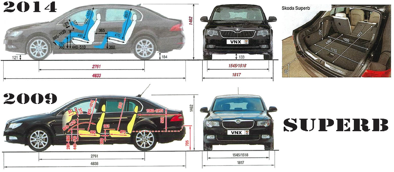
| № | Спецификация / Specs | Данные |
| Габариты (мм/mm) и масса (кг/kg) / Dimensions and Weight | ||
| 1 | Длина / Length | 4833-4838 |
| 2 | Ширина (без/с зеркалами) / Width | 1817/2009 |
| 3 | Высота (загружен/пустой) / Height | 1462 |
| 4 | Колёсная база / Wheelbase | 2761 |
| 5 | Дорожный просвет (клиренс) / Ground clearance | 158⇒133 |
| 6 | Снаряжённая масса / Total (curb) weight | 1511 |
| Полная масса / Gross (max.) weight | 2074 | |
|
Двигатель / Engine |
||
| 7 | Тип / Engine Type, Code | Бензиновый, жидкостного охлаждения, четырехтактный, CDAA (EA888) |
| 8 | Количество цилиндров / Cylinder arrangement: Total number of cylinders, of valves | 4-цилиндровый, рядный, 16V, DOHC с верхним расположением двух распределительных валов |
| 9 | Диаметр цилиндра / Bore | 82.5 мм |
| 10 | Ход поршня / Stroke | 84.2 мм |
| 11 | Объём / Engine displacement | 1798 см³ |
| 12 | Система питания / Fuel supply, Aspiration | Непосредственный впрыск топлива TSI |
| Турбонаддув и промежуточное охлаждение наддувочного воздуха | ||
| 13 | Степень сжатия / Compression ratio | 9.6:1 |
| 14 | Максимальная мощность / Max. output power kW (HP) at rpm | 118 кВт (160 л.с.) при 4500-6200 об/мин |
| 15 | Максимальный крутящий момент / Max. torque N·m at rpm | 250 Нм при 1500-4500 об/мин |
|
Трансмиссия / Transmission |
||
| 16 | Сцепление / Clutch type | Однодисковое, сухое, с диафрагменной нажимной пружиной и гасителем крутильных колебаний, постоянно замкнутого типа |
| 17 | КПП / Transmission type | 02S MQ250-6F МКПП 6 шестиступенчатая механическая, двухвальная, с синхронизаторами на всех передачах переднего хода |
О Книге
- Название: Устройство, обслуживание, ремонт и эксплуатация автомобилей Skoda Superb II. Учебное пособие. Руководство №261
- Бензиновые двигатели: CAXC 1.4 л (1390 см³) 125 л.с./92 кВт, CDAB/BZB/CDAA 1.8 л (1798 см³) 152-160 л.с./112-118 кВт, CCZA 2.0 л (1984 см³) 200 л.с./147 кВт, CDVA 3.6 л (3597 см³) 260 л.с./191 кВт и дизельными CAYC 1.6 л (1598 см³) 105 л.с./77 кВт, ВХЕ/BLS 1.9 л (1896 см³) 105 л.с./77 кВт, BMP/BKD/CBBB/CFFB/CLJA/CFGB 2.0 л (1968 см³) 140-170 л.с./103-125 кВт
- Выпуск с 2008 года
- Серия: «Авторемонт»
- Год издания: 2012
- Автор: Коллектив авторов
- Издательство: «Ассоциация независимых издателей»
- Формат: PDF
- Страниц в книге: 407
- Размер: 52.88 МБ
- Язык: Русский
- Количество электросхем: 25