
СОДЕРЖАНИЕ
I. ТЕХНИЧЕСКОЕ ОПИСАНИЕ МОТОЦИКЛА ЯВА 634 ( JAWA 634 )
1. Техническая характеристика мотоцикла Ява 634 ( Jawa 350 634 8 15 )
2. Описание мотоцикла Ява 634
3. Описание электрооборудования
4. Перечень инструмента
5. Руководство по обслуживанию Ява 350 634
А. Обкатка нового мотоцикла
Б. Перед выездом
В. Пуск двигателя
Г. Движение
6. Чего следует избегать
7. Пояснения с данными о максимальной скорости мотоцикла
II. ТЕХНИЧЕСКОЕ ОБСЛУЖИВАНИЕ МОТОЦИКЛА ЯВА 634
1. План работ по техническому обслуживанию
2. Смазка мотоцикла
3. Очистка мотоцикла
4. Шины
5. Регулировка тормозов
6. Регулировка натяжения
7. Сцепление и его регулировка
8. Карбюратор
9. Воздухоочиститель (микрофильтрующий элемент)
10. Уход за электрооборудованием
11. Аккумуляторная батарея
12. Удаление нагара
13. Хранение мотоцикла в зимний период
III. ДЕМОНТАЖ И МОНТАЖ БЕЗ СПЕЦИАЛЬНОГО ИНСТРУМЕНТА
1. Снятие родного колеса
2. Снятие заднего колеса
3. Снятие задней цепи, кожуха задней цепи и звездочки
4. Монтаж задней цепи
5. Смена шарикоподшипника
6. Смена шарикоподшипников колес
7. Демонтаж головки цилиндра и цилиндра
8. Смена поршневых колец
9. Монтаж цилиндров
10. Снятие карбюратора
11. Смена дисков сцепления
12. Демонтаж спидометра
13. Демонтаж вращающейся рукоятки газа
14. Снятие замка головки руля и седла
15. Снятие аккумуляторной батареи
16. Демонтаж топливного бака
17. Снятие правой и левой крышек двигателя
18. Снятие двигателя с рамы
19. Демонтаж головки руля
20. Демонтаж пера вилки
21. Задняя подвеска
22. Демонтаж задней вилки
23. Смена руля
24. Замена корпуса фары
25. Вынимание замка зажигания
26. Замена контрольных ламп
27. Демонтаж панели приборов
28. Демонтаж передних блинкеров
29. Смена переключателя стоп
IV. НЕИСПРАВНОСТИ ЯВЫ 634 И ИХ УСТРАНЕНИЕ
V. ДОПОЛНЕНИЕ ДЛЯ JAWA 350 ТИПА 634-7-01
Вступление
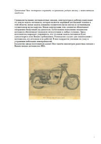
Покупая мотоцикл Ява чехословацкого производства, Вы становитесь владельцем изделия, которое по своим качествам относится к лучшим мировым маркам. Доказательством широкой популярности чехословацких мотоциклов является тот факт, что они поставляются более чем в сто стран мира.
С удовлетворением констатируем, что при выборе марки мотоцикла Вы учли высокое качество машин чехословацкого производства. В целях полного удовлетворения Ваших интересов мы считаем своим долгом следить за состоянием мотоцикла в процессе его эксплуатации и оказывать Вам помощь в устранении возможных дефектов. Выполнение этой задачи возложено на сеть гарантийных ремонтных мастерских, организованных на территории Советского Союза в городах, где имеются магазины по продаже этих изделий.
Гарантийные ремонтные мастерские бесплатно устраняют дефекты, возникшие в Вашем мотоцикле в течение гарантийного срока в том случае, если причина возникновения дефекта будет отвечать действующим гарантийным условиям. В задачу этих мастерских входит также консультация покупателей по эксплуатации и ремонту мотоциклов.
По всем вопросам, касающимся эксплуатации Вашего мотоцикла, обращайтесь исключительно в гарантийную ремонтную мастерскую, где имеются специально подготовленные работники. Завод-изготовитель не имеет возможности содержать специальный аппарат для ответов на многочисленные письма владельцев чехословацких мотоциклов.
К сведению сообщаем, что журнал «За рулем» на своих страницах публикует материалы по эксплуатации, техническому обслуживанию и ремонту мотоциклов Jawa ( ЯВА ).
Следите за выходом из печати этого журнала.
Хотим обратить Ваше внимание на то, что с нашей стороны не могут быть также удовлетворены Ваши просьбы относительно посылки запасных частей, специальных мотоциклов, колясок к мотоциклам и т. д., которые Вы направляете в адрес заводов-изготовителей в ЧССР.
По вопросу приобретения запасных частей к мотоциклам чехословацкого производства после гарантийного срока Вам следует обращаться только в торговую сеть по месту покупки мотоцикла или направлять заказы в адрес специализированной базы Посылторга: г. Москва, Ж-211, Овчиниковская набережная, 8, обязательно указав марку, модель и год выпуска приобретеннго Вами мотоцикла. Владельцев мотоциклов, проживающих в г. Москве, база не обслуживает. Они могут приобрести запасные часта в специализированном магазине «Мотолюбитель»
Заказы должны быть оформлены на специальных бланках «Посылторга», которые имеются во всех почтовых отделениях связи.
Вопросами заказа на поставку запчастей и их распределением по магазинам занимаются республиканские и областные Спортторги и Культторги. Другие организации в опросами продажи запасных частей владельцам мотоциклов не занимаются.
Условия продажи, гарантии и рекомендации
1. При продаже мотоцикла представитель магазина обязан в присутствии покупателя проверить комплектность мотоцикла, работу его узлов и агрегатов на ходу.
2. На мотоцикл установлен гарантийный срок, в течение которого гарантийная мастерская бесплатно производит ремонт мотоцикла, замену его деталей и агрегатов, вышедших из строя по вине завода-изготовителя.
3. Гарантийный срок исчисляется со дня продажи мотоцикла покупателю и действует в течение 6 месяцев. Рекламация подлежит удовлетворению в том случае, если пробег мотоцикла в гарантийный период не превысил 6000 км.
4. Гарантия не распространяется на мотоцикл, вышедший из строя в связи с невыполнением условий эксплуатации, технического обслуживания, изложенных в заводской инструкции.
5. В гарантийный период подлежит удовлетворению рекламация (подтвержденная актом ГАИ и гарантийной мастерской) на мотоцикл, потерпевший аварию по вине завода-изготовителя.
6. Рекламация на мотоцикл в гарантийный период подлежит удовлетворению только при наличии рекламационного акта, оформленного гарантийной мастерской.
ПРЕДОСТЕРЕЖЕНИЕ
Обращаем Ваше внимание на необходимость правильной зарядки аккумулятора и ухода за ним во время эксплуатации; его описание находится в инструкции по обслуживанию. Вследствие невыполнения требовании инструкций аккумулятор может выйти из строя или из него будет вытекать электролит, попадая на ящик и глушитель.

С большим трудом нашёл электронную версию руководства по обслуживанию «Явы»-634.7.00 www.jawaold.com/main.php?sec=books&am, уже скачал, сейчас буду изучать более подробнее. Огромное спасибо интернету, иначе подобное раритетное издание я бы уже нигде не нашёл, а так теперь его уже и распечатать можно для удобства изучения материала
Комментарии
6
Войдите или зарегистрируйтесь, чтобы писать комментарии, задавать вопросы и участвовать в обсуждении.
Руководство по техническому обслуживанию и ремонту мопедов Jawa 50 тип 05.
- Издательство: Мотоков
- Год издания: 1963
- Страниц: 61
- Формат: PDF
- Размер: 3,9 Mb
Руководство по эксплуатации и техническому обслуживанию мопедов Jawa Stadion S22.
- Издательство: —
- Год издания: 1962
- Страниц: 27
- Формат: JPG
- Размер: 9,1 Mb
Техническое описание и инструкция по обслуживанию и уходу мопедов Jawa 50 тип 551.
- Издательство: Мотоков
- Год издания: —
- Страниц: 17
- Формат: DOC
- Размер: 2,0 Mb
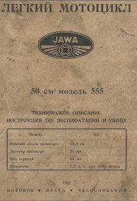
Техническое описание и инструкция по эксплуатации и уходу мокиков Jawa 50 тип 555.
- Издательство: Мотоков
- Год издания: 1962
- Страниц: 24
- Формат: PDF
- Размер: 5,8 Mb
Руководство по техническому обслуживанию и ремонту мотоциклов Jawa-CZ 125 cc модели 355 и 175 сс модели 356.
- Издательство: CZM
- Год издания: 1959
- Страниц: 34
- Формат: PDF
- Размер: 18,9 Mb
Руководство на чешском языке по техническому обслуживанию и ремонту мотоциклов Jawa 125 тип 355, 175 тип 356, 250 тип 353 и 350 тип 354.
- Издательство: —
- Год издания: —
- Страниц: 80
- Формат: PDF
- Размер: 2,4 Mb
Руководство по эксплуатации и техническому обслуживанию мотоциклов Jawa.
- Издательство: Машиностроение
- Год издания: 1969
- Страниц: 135
- Формат: PDF
- Размер: 3,4 Mb

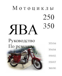
Руководство по ремонту мотоциклов Jawa-250 и Jawa-350.
- Издательство: Машиностроение
- Год издания: 1971
- Страниц: 163
- Формат: PDF
- Размер: 78,3 Mb

Руководство по техническому обслуживанию и ремонту мотоциклов Jawa.
- Издательство: —
- Год издания: —
- Страниц: 254
- Формат: PDF
- Размер: 10,7 Mb
Руководство по эксплуатации и ремонту + каталог запчастей мотоциклов Jawa.
- Издательство: Ранок
- Год издания: 2004
- Страниц: 248
- Формат: PDF
- Размер: 20,0 Mb
Руководство по эксплуатации, техническому обслуживанию и ремонту мотоциклов Jawa моделей 353/04 и 354/04.
- Издательство: —
- Год издания: —
- Страниц: 46
- Формат: DOC
- Размер: 2,1 Mb
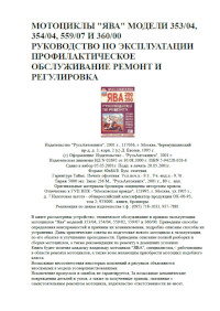
Руководство по эксплуатации, техническому обслуживанию и ремонту мотоциклов Jawa моделей 353/04, 354/04, 359/07 и 360/00.
- Издательство: РусьАвтокнига
- Год издания: 2001
- Страниц: 156
- Формат: PDF
- Размер: 2,0 Mb
Руководство по ремонту мотоциклов Jawa 250/350 моделей 353/04, 354/04, 559/02, 559/07 и 360/00.
- Издательство: —
- Год издания: —
- Страниц: 312
- Формат: DOC
- Размер: 3,4 Mb
Руководство по техническому обслуживанию мотоциклов Jawa 250/350 моделей 559/04 и 360/00.
- Издательство: —
- Год издания: 1967
- Страниц: 63
- Формат: DOC
- Размер: 1,4 Mb
Руководство на английском языке по техническому обслуживанию и ремонту мотоциклов Jawa 350 моделей 634 и 568.
- Издательство: —
- Год издания: 1989
- Страниц: 53
- Формат: PDF
- Размер: 35,7 Mb
Руководство по техническому обслуживанию мотоциклов Jawa 350-634.
- Издательство: —
- Год издания: 1975
- Страниц: 47
- Формат: JPG
- Размер: 13,3 Mb
Руководство по техническому обслуживанию мотоциклов Jawa 350/634-7-00/01.
- Издательство: —
- Год издания: 1981
- Страниц: 53
- Формат: JPG
- Размер: 17,7 Mb
Руководство по техническому обслуживанию мотоциклов Jawa 350-638.
- Издательство: —
- Год издания: 1990
- Страниц: 49
- Формат: JPG
- Размер: 2,6 Mb
Руководство по техническому обслуживанию и ремонту + каталог запчастей мотоциклов Jawa 350-638.
- Издательство: РусьАвтокнига
- Год издания: —
- Страниц: 134
- Формат: PDF
- Размер: 4,9 Mb
Руководство по техническому обслуживанию и каталог запчастей мотоциклов Jawa 350/638/5.
- Издательство: —
- Год издания: 1984
- Страниц: 92
- Формат: PDF
- Размер: 19,2 Mb

Руководство на чешском языке по техническому обслуживанию и ремонту мотоциклов Jawa 3638/640/640-1.
- Издательство: —
- Год издания: —
- Страниц: 88
- Формат: DOC
- Размер: 6,2 Mb
Руководство по техническому обслуживанию мотоциклов Jawa 350/640 Styl/Policie/Tramp.
- Издательство: ЯВА
- Год издания: 1995
- Страниц: 67
- Формат: PDF
- Размер: 5,2 Mb
В практическом пособии приведены устройство и технические данные легких (без коляски) мотоциклов отечественного производства, чехословацких ЯВА и ЧЗ, а также спортивных. Помещены указания по их демонтажу, сборке и ремонту отдельных деталей, сведения по обкатке, эксплуатации и техническому обслуживанию.
- Издательство: Техника
- Год издания: 1984
- Страниц: 98
- Формат: DjVu
- Размер: 2,6 Mb
В руководстве представлена информация об устройстве и работе всех узлов и агрегатов мотоцикла.
- Издательство: Алфамер
- Год издания: —
- Страниц: 220
- Формат: —
- Размер: —
Сборник инструкций на русском и чешском языках по монтажу и настройке комплекта боковой коляски Велорекс для мотоциклов Jawa.
- Издательство: —
- Год издания: —
- Страниц: —
- Формат: PDF
- Размер: 10,2 Mb

- Manuals
- Brands
- JAWA Manuals
- Motorcycle
- F 350/634-5,8
- Owner’s handbook manual
-
Contents
-
Table of Contents
-
Bookmarks
Quick Links
Related Manuals for JAWA F 350/634-5,8
Summary of Contents for JAWA F 350/634-5,8
-
Page 2
MOTOR CYCLE 350 ––634-5,8 OWNER’’S HANDBOOK Manufacturer: JAWA, n. p., Tynec n/Sazavou Exporters: MOTOKOV — Praha 1979 Edition (451 9 634 00 083) -
Page 5
We highly value the trust you have shown in our make by choosing one of our machines and welcome you into the large world family of JAWA motorcycle enthusiasts which already includes many hundreds of thousands of members and which continues to grow from year to year. -
Page 6: Table Of Contents
C O N T E N T S DESCRIPTION AND TECHNICAL SPECIFICATIONS OF MOTOR CYCLE 1. Technical date…………………………………………………………………………………………………………………………………… 7 2. Description of motor cycle ………………………………………………………………………………………………………… 10 3. Description of electrical equipment …………………………………………………………………………………….. 15 4. List of tools ………………………………………………………………………………………………………………………………………… 18 5. Handling instructions ……………………………………………………………………………………………………………………. 19 A.
-
Page 7
4. Installation of secondary chain ………………………………………………………………………………………………………………. 60 5. Replacement of chain wheel bearing …………………………………………………………………………………………………… 65 6. Replacement of wheel ball bearings ……………………………………………………………………………………………………. 65 7. Removal of cylinder heads and barrels ………………………………………………………………………………………………. 65 8. Replacement of piston rings ……………………………………………………………………………………………………………………. 66 9. Assembly of complete cylinders …………………………………………………………………………………………………………… 66 10. -
Page 8: Technical Date…
TECHNICAL DESCIPTION OF JAWA 350 TYPE 634-5,8 MOTORCYCLE 1. TECHNICAL DATA Engine air-cooled two stroke Number of cylinders Bore 58 mm Stroke 65 mm Swept volume 343.47 c.c. Compression ratio 9.2 : 1 Ignition dynamo-battery system Maximum engine output 17.7 kW –– 87 .s (-1) (28 h.p.
-
Page 9
Primary transmission Primary chain 2 x 9.525 x 4.77 66 links –– fully enclosed Secondary transmission Secondary chain 1 x 12.7 x 7.75 128 links incl. end link Gear ratios: 47/29; 1 : 1.62 Primary 52/18; 1 : 2.89 1st-speed gear 19/12 x 24/12 1 : 3.16 2nd-speed gear… -
Page 10
Fig. 2 –– Sectional view of engine… -
Page 11: Description Of Motor Cycle …
2. DESCRIPTION OF THE MOTOR CYCLE The JAWA motorcycles are single-track motor vehicles used for the transport of one or two persons and luggage up to a total load of 180 kg. They are designed for driving on motor roads and well-conditioned subsidiary roads.
-
Page 12
The four-speed gearbox has sliding gears. The foot-operated gear shift lever is on the left-hand side of the engine. The engine is kickstarted by using the gear shift lever. Chains are used for the primary and secondary transmission. The primary chain is covered by the left-hand engine cover and runs in an oil bath. -
Page 13
The spoke wheels running in ball bearings are easy to detach, their spindles being of the push-out type. The connection of the rear wheel with the rear chain wheel incorporates a rubber drive torque damper. The rear wheel can be removed with disconnecting the chain. The brakes are mechanical with dia. -
Page 14
Important! The JAWA National Corporation does not supple or manufacture spare keys for the lock of the seat and the steering lock. Therefore, take good care of the spare set of keys and, if you lose one key, have a duplicate made… -
Page 16: Description Of Electrical Equipment …
H –– Grey The ignition is of the dynamo battery system. The rating of the six-pole dynamo or JAWA make is 75 W and 6 The dynamo-stator or yoke is fixed by two screws to the crankcase. It carries the contact breakers, carbon brushes and capacitors.
-
Page 17
POSITION OF IGNITION KEY IN SWITCH BOX Key position Key half-way in Key pushed fully home horn and headlamp flasher switched on ignition and direc- switched on tion indicators (in the case of a defect or after removal of the battery shift into 2 gear and push start the machine, — the… -
Page 18
Fig. 7 –– Location of stop-switch ELECTRICAL ACCESSORIES In the headlamp there is a 6V/35W twin-filament bulb and a 6V/4W parking bulb The rating of the tail-light bulb is 6V/5W, of the stop-light 6V/15W. The rating of the direction indicator bulbs is 6V/15W or 6V/21W. Telltale lamps are rated for 6V/2W. -
Page 19: List Of Tools …
LIST OF TOOLS Tyre inflator complete………………………………………………………………………………………………………………………….. 1 Combination spanner No. 32 ……………………………………………………………………………………………………………… 1 Feeler gauge ……………………………………………………………………………………………………………………………………………….. 1 Double screwdriver ………………………………………………………………………………………………………………………………… 1 Screwdriver, 3mm ……………………………………………………………………………………………………………………………………. 1 Tommy ………………………………………………………………………………………………………………………………………………………….. 1 Lever with hook spanner 19 ……………………………………………………………………………………………………………….. 1 Spanner 5.5 x 7 …………………………………………………………………………………………………………………………………………. 1 Spanner 8 x 10 …………………………………………………………………………………………………………………………………………..
-
Page 20: Handling Instructions …
5. HANDLING INSTRUCTIONS A. RUNNING-IN A NEW MACHINE After having purchased a new machine, the customer is advised to check the equipment stowed in the left-hand box and in the compartment under the seat for completeness and to compare the engine and frame numbers with the supplied documents.
-
Page 21
Chapter II, Art. 8 ““Carburettor””, after the machine has been run in. JAWA motorcycles have very efficient air intake and exhaust silencers which lower the machine noise level to a value complying with the pertinent traffic code regulations. This results, quite naturally, in a relatively higher audibility of all the mechanical noises which were formerly drowned by the noise of the air intake and the exhaust. -
Page 22: Before Starting …
efficient damping of the air intake and exhaust noise. Their intensity depends on the degree of choking of the exhaust silencers and the air-intake micromesh filter, which must, therefore, be kept in a clean condition. In this connection, we wish to draw attention to the fact than no intervention in the air intake and exhaust silencers is permitted.
-
Page 23
Stroke, B.P. Two Stroke, or Control Two Stroke brands in a ratio of 1 to 33 (3%) (after running-in). It is important to stir the mixture thoroughly. The fuel tank is fitted with a lever type fuel cock which ensures a fuel for about 50 km (30m.) (depending on the condition of the road and the travelling speed). -
Page 24: Starting …
Be sure to adjust both suspension units in the same position. The third, adjustable suspension type with different springs has been taken over from CZ motor cycles (Fig. 42C). When fitted on JAWA machines, it has three adjusting positions obtainable as in the case of the second suspension type.
-
Page 25: Driving …
D. DRIVING a) Depress the clutch lever with your left hand, and depress the gear lever (pushing down). Then slowly release the clutch lever with opening the throttle gradually. Pull away immediately, never stand with the gear engaged and the clutch released for a proloned period. This applies also when wasiting on crossings. A prolonged slipping of the clutch leads to over heating and premature wear of the clutch plates.
-
Page 26: Data On Peak Speed Values …
6. DATA ON PEAK SPEED VALUES The peak speed as specified in this manual is the top limit of the maximum speed attainable by the motor cycle under optimum conditions. The actual speed of the machine can be determined only by using a stop watch to measure the speed on straight stretch of a road while driving in both directions to eliminate the effect of the wind and the deviations of the stretch from the horizontal plane.
-
Page 27: Maintenance
MAINTENANCE 1. MAINTENANCE SCHEDULE (jobs to be done in a specialized shop are marked ““*””) New Machine (unless a guarantee inspection has taken place) Removing transport blinding plugs from front fork leg nuts Check the machine equipment for completeness Check the oil level in the gearbox Check the charged condition of the storage battery Check the lights Check the direction indicators…
-
Page 28
****************************************************************************************** After every 5,000 km Checking and topping up of the lubricant, if necessary Clean and lubricate the bowden cables of the front brake and Clutch, foot-operated brake, twistgrip, the brake cams and the Pins of the stand, and clean the exhaust pipe cores. After the first: 500 km Change the gearbox oil… -
Page 29: Lubrication …
***************************************************************************************** 15,000 km Change the oil in the front fork shock absorbers Replace the intake silencer micromesh filter Replace the secondary chain and change the lubricant in the chaincase Replace the sparking plugs *Lubricate the steering head bearings Inspect the front tyre tread (if the tread pattern is worn down to 1 mm, change the tyre) 20,000 km Change the gearbox oil…
-
Page 32
Gearbox: Change the oil in the gearbox once a year after running-in, preferably at the end of the motorcycling season, or after every 10,000 km. The same oil brand can be used in summer and in winter. The filling is 1.2 litre. -
Page 33
Fig. 13 — — a) filler hole, b) check plug Front fork shock absorber. After having travelled the first 1,000 to 1,500 kilometres (600 –– 1000 m.) change the damper oil in the front fork legs. Proceed as follows: Remove the front wheel put a vessel under the front fork leg to take the drained oil, and remove the screw (5) from the bottom part of the slider which fastens the shock absorbed end to the slider bottom. -
Page 35
(to prevent the pin from slipping out of the recess), remove the auxiliary screw, and replace it with the original screw after inserting the washer (17) and the sealing ring (18). It is adviseable to use always a new sealing ring. Repeat the same procedure with the other fork leg. -
Page 36
The rear dampers have a high damping effect and do not require topping up of oil. However, it is recommended to change the oil after every 10,000 to 15,000 kilometres (6,000 –– 9,500 miles). For the oil change, cleaning and repairs of the dampers, rely on a specialized service station or repair shop. Wheels. -
Page 37: Cleaning …
3. CLEANING The smooth contours of the JAWA motor cycles facilitate cleaning. Use only water or a car shampoo for washing the machine. Dirt should be removed from the engine with tetrachlorethane or kerosene. When using inflammable preparations or substances for cleaning metal (not paint coated) parts, proceed with extra caution.
-
Page 38
Fig. 15 –– Dismounting of tyre along the entire circumference of the rim. Screw off the nut fastening the valve to the rim and push the valve into the rim. When placing the wheel on the ground make sure that no foreign matter can get into the bearings. Press the tyre bead into the rim base opposite to the valve and slip the tyre bead over the rim edge next to the valve using the tyre levers. -
Page 39
Fig. 16 Fitting of tyre Inflate the tube partially, insert it into the tyre casing one bead of which has remained in the rim, thread the valve through the hole in the rim and secure it in position with the nut (do not tighten the nut for the time being). Fig. -
Page 40
Starting opposite the valve, slip the tyre bead over the rim edge inside the rim, hold it down in the rim base, and, using the tyre levers, proceed to slip over the tyre bead on both sides alternately till one arrives at the valve. Be certain not to damage the air tube by nipping and take care that foreign matter (sand) does not get inside the tyre. -
Page 41: Adjustment Of Brakes …
5. ADJUSTMENT OF BRAKES (Fig. 18) The motor cycle brakes require an occasional adjustment when a prolonged travel of the brake lever and brake pedal calls this fact to your attention. It is due to the gradual wear of the brake shoe lining. Front brake adjustment: a) First, loosen sufficiently the nut M 6 (1) of the connecting link.
-
Page 42: Chain Tensioning …
Caution! Correct adjustment of the front double-cam brake is very important to prevent burning of one of the brake shoes. Fig. 20 –– Measuring of line-up plane of wheels 6. CHAIN TENSIONING (Fig. 19) The maintenance of the chain and a correct adjustment of its tension are decisive for its life and function. The most important is its sufficient slack in every position of the swinging fork.
-
Page 43: Clutch And Its Adjustment …
d) When adjusting the chain slack make sure that both wheels are aligned, i.e., that the rear wheel follows the track of the front wheel. For measuring the line-up plane of the wheels, use a suitably adapted lath (see Fig. An incorrect wheel alignment affects adversely the riding properties of the motor cycle.
-
Page 44: Carburettor …
b) Screw down slightly the clutch cable adjusting screw (on bowden cable under the frame head ) to shorten the cable and to release the clutch lever; c) Clean the cam (9) of the automatic clutch release lever (10) with pertol or kerosene; d) Hold the clutch release lever (10) with the fingers of your left hand and swing the lever toward the cam and back;…
-
Page 45: Air Cleaner …
Fig. 22 –– Sectional view of carburettor…
-
Page 46
CARBURETTOR SETTING Carbur- Motor ettor Main Idling Needle Pilot air Cycle type model position screw 634-5,8 2926 notch backed off 350 cc SBDb running-in from top by ½ turn after notch backed off by running-in from top 0.5 –– 1.5 turn It is recommended not to tamper with the carburettor in any way, with the exception of its washing in petrol and setting in accordance with the Table. -
Page 47
Fig. 23 –– Removal of intake silencer body Clean the micromesh filter after every 2,500 kilometres (1,550 miles) by knocking out or, preferably, blowing out the trapped dirt. When blowing out the dirt by compressed air, proceed from the centre of filter element. It is not permitted to wash the micromesh filter or moisten it with oil and the like. -
Page 48
Remove the seat and the fuel tank and lift away the plastic sealing cover preventing the ingress of dirt into the compartment under the seat. Using a tubular spanner (10), remove the bolt fastening the intake silencer body to the frame, tilt the body forward, and disengage it carefully from the frame. -
Page 49: Maintenance Of Electrical Equipment …
10. MAINTENANCE OF ELECTRICAL EQUIPMENT Inspect the cables occasionally and replace those with a damaged insulation. From time to time, clean the sparking plug, scrape off carefully the carbon deposits, and, if necessary, adjust the electrode gap to 0.6 –– 0.7 mm (on PAL sparking plugs) by bending the electrode on the sparking plug body. It is advisable to replace the sparking pug with a new one after having covered 15,000 kilometres (9,500 miles).
-
Page 50
Fig. 26 –– Stop-switch replacement Headlamp adjustment. Adjust the correct distance at which the dipped beam has to light the roadway by moving the entire headlamp up or down after having slackened both side screws holding the headlamp in position. The dipped beam must be light a stretch of about 25 metres with the driver riding alone. The circuit breaker of flashing direction indicators ––… -
Page 51
Bolt to find the piston TDC. Draw an index line on the rod marking this position. Take out the rod and draw another line at the specified distance (see point c) above the first index line. b) With the piston in its TDC check the contact points for contamination and, if necessary, smooth their contact faces with a fine file so that they mate perfectly when the contacts are closed. -
Page 52
Fig. 28 –– Measuring of contact breaker point gap c) Ascertain, whether the piston is still in its TDC and lower the piston by the specified advance value, i.e., 2.7 to 3.2 mm, by rotating the crankshaft anticlockwise (in opposite direction). d) In this new position, check again the contact breaker point gap. -
Page 53: Storage Battery …
Remove the brush spring retainer carefully so as not to break off the bakelite protrusion of the brush holder. Dirty brushes cannot move in the guides. Remove them and clean them with petrol. Do not use a file on the friction surfaces of the brushes.
-
Page 54
Fig. 29 –– Sectional view of storage battery However, there still persists the danger of the chromium plated parts being damaged by the spilled over electrolyte. Take care that the overflow hose is not damaged or clogged and that its end is positioned so that the escaping electrolyte vapours cannot damage any parts of the machine. -
Page 55
Putting a new storage battery into service 1. Unscrew the plugs and remove the degassing mechanism from the storage battery. Fill the three battery cells with chemically pure sulphuric acid (never of an industrial brand) diluted with distilled water to obtain a specific of 1.26 (1.23 in tropical regions) and take care not to surpass the level of the first cross partition above the plates (see Fig. -
Page 56: Decarbonizing …
Battery maintenance 1. Keep the battery and its terminals clean and dry. Coat lightly the connecting screws and cable lugs with grease to protect them against the detrimental effects of the sulphuric acid. 2. Check the electrolyte level at least once in a fortnight (or every 1,000 km). If necessary, add distilled water to obtain the specified level (see Fig.
-
Page 57
Fig. 30 –– Removal of exhaust silencer core Fig. 31 –– Sectional view of exhaust silencer… -
Page 58: Stabling Of Motor Cycle In Winter …
13. STABILING OF MOTOR CYCLE IN WINTER 1. If you intend to use the motor cycle at irregular intervals in winter, stable it in a dry and, if possible, heated garage. Put the motor cycle in the garage with a well-heated engine so as to prevent condensation of water vapour on the interior parts of the engine and their corrosion.
-
Page 59: Front Wheel Removal …
III. DISMANTILING AND ASSEMBLING JOBS REQUIRING NO SPECIAL TOOLS 1. FRONT WHEEL REMOVAL Detach the bowden cable from the brake cam lever. Remove the cotter pin, screw off the wheel spindle nut, and lift away the spring washer. Loosen the clamping bolt on the right-hand slider end, push out the spindle and remove the wheel.
-
Page 60: Rear Wheel Removal …
Fig. 33 –– Removal of chaincase front part 2. REAR WHEEL REMOVAL Unscrew the wing nut of the rear brake bowden cable and the wheel spindle nut, lift away the spring washer, and push out the spindle in the right-hand direction. On the left-hand side of the machine, remove the catch of the brake reaction, the spacer, and push out the wheel from the carrier.
-
Page 61
c) Using the 32 mm spanner, unscrew the nut of the rear chain wheel and lift away the entire chaincase rear half including the rubber sleeves and chain. d) Remove the screws of the rear clamps and pull the rubber sleeves off the two-part chaincase. After having unscrewed the two M 5 nuts, separate both halves of the chaincase and lift away the chain wheel with the chain. -
Page 62
b) Use a length of thick wire with a hooked end to pull the chain through both rubber sleeves and slip the ends of the sleeves over the mounting of the two-part rear chaincase securing them with the clamps. c) Place the top end of the chain with the end link over the secondary sprocket next to the gearbox. Fit the chain tensioner on the leg of the rear swinging fork while slipping the chain wheel hub into position. -
Page 63
Fig. 35 –– Replacement of secondary chain Before disconnecting again the end link, secure both ends of the installed chain in the manner as per point c), and disconnect and remove the original chain. Having thus replace the chain with a new one, lock it using the new link, and proceed as per point f). -
Page 64
Fig. 36 –– Sectional view of front wheel… -
Page 65
Fig. 37 –– Sectional view of rear wheel… -
Page 66
5. REPLACEMENT OF CHAIN WHEEL BEARING (Fig. 37) After having removed the rear wheel, screw off the chain wheel nut using the 32 mm spanner. Lift away the chain wheel and the chaincase from the swinging for leg. Remove the clamps from the rear ends of the rubber sleeves and screw out the two M 5 bolts to separate both halves of the chaincase. -
Page 67
the piston in to its BDC position and remove the cylinder barrels carefully so that no foreign matter gets into the engine and so as not to damage the gasket common for both cylinder barrels. Cover the opening of the crankcase. The cylinder heads and barrels should be removed only when removing carbon deposits, replacing the piston rings or the gaskets. -
Page 68
Fig. 38 –– Replacement of piston rings 10. CARBURETTOR REMOVAL a) Detach the fuel supply hose from the tank. b) Unscrew the nut of the throttle chamber and lift away the throttle valve with the bowden cable and the needle. c) Detach the rubber connection (sleeve) connecting the carburettor with the intake silencer body. -
Page 69
Caution! To avoid a distortion of the flange or breaking of the bakelite interface liner, do not use excessive force when tightening the nuts fastening the carburettor to the crankcase. Before assembling the carburettor and the interface liner, it is advisable to check the mating surface of the flange and interface liner for perfect flatness and level off their unevennesses, if any. -
Page 70
12. SPEEDOMETER REMOVAL First screw off the speedometer drive holddown nut from the speedometer lower part thus releasing the bottom of the speedometer casing, then lift away the casing. Slide out the illumination lamp holder including the lead from the speedometer and/or disconnect the connector connection. Using a 22 mm spanner, screw off the nut fastening the speedometer to the bracket and remove the speedometer with its plastic casing. -
Page 71
Fig. 40 –– Removal of seat and lock 16. FUEL TANK REMOVAL Turn off the fuel cock and detach the fuel hose. After lifting away the seat, loosen both M 6 bolts of the fuel tank rear silentblock using a socket spanner No. 10, and then lift away the silentblock by pulling the heads on the bolts with pliers. -
Page 72
17. REMOVAL OF LEFT-HAND AND RIGHT-HAND ENGINE COVER The right-hand cover has to be removed when adjusting the clutch release mechanism or the ignition. Remove the two bolts fastening the cover and lift away the cover carefully. Before refitting it, clean the mating surfaces. Tighten the fastening bolts uniformly so that the front part of the cover bears correctly against the crankcase. -
Page 73
nut using a 32 mm box spanner. With the slackened secondary chain, push out the secondary sprocket with the chain and the inner guard from its mounting. Do not uncouple the chain! Remove the bolts fastening the engine to the frame. Then, standing on the left-hand side of the machine, grip the right-hand cylinder at the exhaust port with your left hand, and the kickstarter lever with your right hand. -
Page 74
20. FRONT FORK LEG REMOVAL For this job it is recommended to make a simple fixture, with the aid of which the fork leg can be easily slipped out of the upper and lower front fork lugs and refitted into them. To make this fixture, weld a tube with a drip (Fig. -
Page 75
Loosen the nut of the lower fork lug clamping bolt and tap the fixture carefully to drive out the fork leg (in the downward direction). Bend slightly the wing strut so that it is not in the way of the slider nut with its packing. Headlamp brackets, the headlamp and the front direction indicators remain in position. -
Page 76
C. Rear suspension with four-position hardness adjusting with springs uncovered, used on CZ 350 motor cycles. Only three of the adjusting positions can be used on JAWA 350-634 motor cycles. 1. When changing the oil or replacing the piston cup of the type ““1”” suspension, remove the suspension from the machine and dismantle it partly after having placed it between the open jaws of a vice, compress the spring, and remove the split retainer (1). -
Page 77
3. To dismantle partly the type ““3”” suspension, remove it from the machine frame and first reset the hardness adjusting sleeve into its basic position, i.e., the position for the smallest preload of the spring. Open the vice and place the sleeve with its lower part between the jaws. Now press down the sleeve by about 5 mm and rotate the lower lug of the suspension damper clockwise. -
Page 78
23. REMOVAL OF DIRECTION INDICATORS Remove the screw M 6 fastening the earthing cable and the cable with the cable sling to the upper front fork lug. Loosen the rear fuel tank bolts, lift away the spring from the front retainer, and swing off the fuel tank. Disconnect the connectors of the respective direction indicator leads from the connector terminal strip. -
Page 79
Disassembly and assembly of the engine, requiring not only special tools but also skill and experience, are not described in this manual. It is advisable to have any major repair carried out in a specialized JAWA repair shop. JAWA National Corporation…