-
Contents
-
Table of Contents
-
Bookmarks
Quick Links
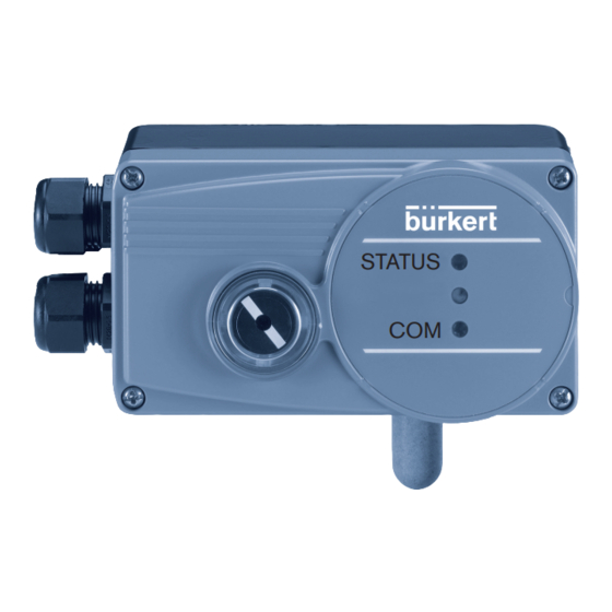
Type 8791 REV.2
Positioner SideControl BASIC
Electropneumatic positioner
STATUS
COM
Operating Instructions
Related Manuals for Burkert 8791 REV.2
Summary of Contents for Burkert 8791 REV.2
-
Page 1
Type 8791 REV.2 Positioner SideControl BASIC Electropneumatic positioner STATUS Operating Instructions… -
Page 2
We reserve the right to make technical changes without notice. Technische Änderungen vorbehalten. Sous réserve de modifications techniques. © Bürkert Werke GmbH & Co. KG, 2009 – 2020 Operating Instructions 2002/02_EU-EN_00815310 / Original DE… -
Page 3: Table Of Contents
Type 8791 REV.2 Electropneumatic positioner Type 8791 REV.2 ontents ABOUT THESE INSTRUCTIONS ………………….8 Symbols ……………………….8 1.2 Definition of terms ……………………8 INTENDED USE ……………………….9 BASIC SAFETY INSTRUCTIONS ………………….10 GENERAL INFORMATION ……………………11 4.1 Contact addresses ……………………11 4.2 Warranty ………………………..11 4.3 Information on the Internet ………………….11 DESCRIPTION OF SYSTEM …………………….12 5.1 General description ……………………12 5.1.1…
-
Page 4
Type 8791 REV.2 8.3 Operating conditions …………………….22 8.4 Mechanical data …………………….22 8.5 Type label ………………………23 8.6 Electrical data ……………………..23 8.6.1 Electrical data, without fieldbus communication …………23 8.6.2 Electrical data, IO-Link ………………..24 8.6.3 Electrical data, büS …………………24 8.7 Pneumatic data ……………………..24 8.8 Safety end positions after failure of the electrical or pneumatic auxiliary power ….25 8.9 Factory settings of the positioner …………………26 8.9.1 Functions can be activated via DIP switches ………….26 8.9.2… -
Page 5
Type 8791 REV.2 10.1.5 RESET — Reset to factory settings …………………41 10.1.6 X.TUNE — Automatic calibration of the position controller to the relevant operating conditions 41 10.2 Additional functions ……………………42 10.2.1 DIR.ACT — Reversal of the effective direction of the actuator …………43 10.2.2 SPLTRNG — Signal split range ………………….44 10.2.3… -
Page 6
Type 8791 REV.2 FLUID CONNECTION ………………………61 12.1 Safety instructions ……………………61 ELECTRICAL INSTALLATION, WITHOUT FIELDBUS COMMUNICATION ……….63 13.1 Safety instructions ……………………63 13.2 Electrical installation with circular plug-in connector ………….63 13.2.1 Designation of the circular plug-in connector …………63 13.2.2 Pin assignment for input signals from the control centre (e.g. PLC) ……64 13.2.3… -
Page 7
Type 8791 REV.2 BÜS ………………………….74 18.1 Information, büS …………………….74 18.2 Configuration of the fieldbus …………………74 SERVICE …………………………75 ACCESSORIES ………………………..75 20.1 Communications software ………………….75 TRANSPORTATION, STORAGE, DISPOSAL ………………76 english… -
Page 8: About These Instructions
▶ Indicates an instruction for risk prevention. → Indicates a procedure which you must carry out. Indicates a result. Menu Indicates a interface text. Definition of terms In these instructions the term “device” denotes the following device types: Positioner Type 8791 REV.2 The term “büS” (Bürkert system bus) used in this instruction stands for the communication bus developed by Bürkert and based on the CANopen protocol. In these instructions, the abbreviation “Ex” always refers to “potentially explosive area”. english…
-
Page 9: Intended Use
Type 8791 REV.2 Intended use INTENDED USE The Positoner Type 8791 REV.2 is designed to be mounted on pneumatic actuators of process valves for the control of media. The permitted fluid media are listed in the technical data. ▶ Use the device for its intended purpose only. Non-intended use of the device may be dangerous to peo- ple, nearby equipment and the environment. ▶ Correct transportation, correct storage as well as correct installation, commissioning, operation and maintenance are essential for reliable and problem-free operation.
-
Page 10: Basic Safety Instructions
Type 8791 REV.2 Basic Safety Instructions BASIC SAFETY INSTRUCTIONS These safety instructions do not consider any contingencies or incidents which occur during installation, operation and maintenance. The operator is responsible for observing the location-specific safety regulations, also with reference to the personnel. DANGER Risk of injury from high pressure and discharge of medium. ▶ Before working on the device or system, switch off the pressure. Vent or drain lines. DANGER Risk of injury from electric shock. ▶ Before working on the device or system, switch off the power supply. Secure against reactivation. ▶ Observe applicable accident prevention and safety regulations for electrical equipment.
-
Page 11: General Information
Type 8791 REV.2 General Information GENERAL INFORMATION Contact addresses Germany Bürkert Fluid Control Systems Sales Center Christian-Bürkert-Str. 13-17 D-74653 Ingelfingen Tel. + 49 (0) 7940 — 10 91 111 Fax + 49 (0) 7940 — 10 91 448 E-mail: info@buerkert.com International Contact addresses can be found on the final pages of these printed operating instructions.
-
Page 12: Description Of System
Type 8791 REV.2 Description of System DESCRIPTION OF SYSTEM General description The positioner Type 8791 is a digital, electropneumatic positioner for pneumatically actuated continuous valves. The device incorporates the main function groups — Position sensor — Pilot valve system (electropneumatic control system) — Microprocessor electronics The position sensor measures the current positions of the continuous valve.
-
Page 13: Combination With Valve Types And Mounting Versions
Type 8791 REV.2 Description of System • Mounting on linear actuator according to NAMUR recommendation (DIN IEC 534-6) or on rotary actuator according to VDI/VDE 3845. • Optional Remote version for standard rail mounting or for mounting bracket 5.1.2 Combination with valve types and mounting versions The positioner Types 8791 can be mounted on different continuous valves. For example on valves with…
-
Page 14: Overview Of The Mounting Options
Type 8791 REV.2 Description of System 5.1.4 Overview of the mounting options Mounting NAMUR on rotary actuator Mounting NAMUR with mounting bracket on a linear actuator Remote mounting with mounting bracket Remote mounting with standard rail Table 1: Overview of the mounting options…
-
Page 15: Structure
Type 8791 REV.2 Structure STRUCTURE The positioner Type 8791 consist of the micro-processor controlled electronics, the position sensor and the pilot valve system. The unit is operated via 2 buttons and 4 DIP switches. 2 LEDs (1 RGB LED for device status and 1 green LED for communication interface status) indicate the dif- ferent statuses of the unit.
-
Page 16: Function
Type 8791 REV.2 Function FUNCTION Function diagram Diagram illustrating single-acting actuator Compressed-air Control valve with supply Positioner Type 8791 single-acting actuator Position set- point value Positioner Pilot valve system* Exhaust air Position sensor Actual position * Pilot valve system 1: Aeration valve 2: Bleed valve…
-
Page 17: Function Of The Position Control
Type 8791 REV.2 Function Function of the position control The position sensor records the current position (POS) of the pneumatic actuator. The positioner compares this actual position value with the set-point value (CMD) which is a standard signal. If there is a control difference (Xd1), the actuator is aerated and deaerated via the control system. In this way the position of the actuator is changed until control difference is 0. Z1 represents a disturbance variable.
-
Page 18: Schematic Representation Of The Position Control
Type 8791 REV.2 Function 7.2.1 Schematic representation of the position control 1) Can be activated with communica- tions software only Figure 4: Schematic representation of position control english…
-
Page 19: Functions Of The Position Controller Software
Type 8791 REV.2 Function 7.2.2 Functions of the position controller software Basic functions • Activation via DIP switches • Parameter setting via communications software Function Effect Sealing function Valve closes tight outside the control range. Speci- fication of the value (as %) from which the actuator CUTOFF is completely deaerated (when 0%) or aerated (when 100%) (see chapter entitled “9.3.2 Function of the DIP switches”).
-
Page 20
Type 8791 REV.2 Function Auxiliary functions • Activation and parameter setting with communications software Function Effect Reversal of the effective direction of the actuator Assignment of the aeration status of the actuator chamber to the actual position. DIR.ACT Signal split range Standard signal as % for which the valve runs through the entire mechanical stroke range. SPLTRNG… -
Page 21: Interfaces Of The Positioner
Type 8791 REV.2 Function Interfaces of the positioner Input for position Analog position set-point value feedback 4 – 20 mA (variant) Positioner 0 – 20 mA 3- or 4-wire Proximity switch 1, Digital input Proximity switch 2 24 V PNP NO…
-
Page 22: Technical Data
Type 8791 REV.2 Technical data TECHNICAL DATA Conformity In accordance with the EU Declaration of conformity, the positioner Type 8791 is compliant with the EU Directives (if applicable). Standards The applied standards on the basis of which compliance with the EU Directives is confirmed are listed in the EU type examination certificate and/or the EU Declaration of Conformity (if applicable). Operating conditions WARNING! Solar radiation and temperature fluctuations may cause malfunctions or leaks. ▶ If the device is used outdoors, do not expose it unprotected to the weather conditions.
-
Page 23: Type Label
Type 8791 REV.2 Technical data Type label Type Operating voltage Nominal power Device variant, communication, version 8791 24V DC 5W Operating pressure, degree of protection Remote IO-Link REV.2 Ambient temperature P=1.4…7bar IP65/67 Tamb –10…+60°C Approval marking CSA (for Canada and USA) ®…
-
Page 24: Electrical Data, Io-Link
Type 8791 REV.2 Technical data 8.6.2 Electrical data, IO-Link Protection class III as per DIN EN 61140 (VDE 0140-1) Connection Circular plug-in connector M12 x 1, 5-pin, A-coded, Port Class B Operating voltage System supply (Pin 1+3) 24 V DC ±25 % (according to specification) Actuator supply (Pin 2+5) 24 V DC ±25 % (according to specification) Current consumption System supply (Pin 1+3) max.
-
Page 25: Safety End Positions After Failure Of The Electrical Or Pneumatic Auxiliary Power
Type 8791 REV.2 Technical data Safety end positions after failure of the electrical or pneumatic auxiliary power The safety end position depends on the fluid connection of the actuator to the working connections A1 or A2. Safety end positions after failure of the Actuator system Designation pneumatic electrical auxiliary power auxiliary power down single-acting → Connection according to “Figure 7” down Control function down → Connection according to “Figure 8”…
-
Page 26: Factory Settings Of The Positioner
Type 8791 REV.2 Technical data Factory settings of the positioner 8.9.1 Functions can be activated via DIP switches Function Parameter Value CUTOFF Sealing function below Sealing function above 98 % CHARACT Characteristic correction FREE DIR.CMD Reversal of the effective direction set- point value Table 6: Factory settings 8.9.2…
-
Page 27: Operating
Type 8791 REV.2 Operating OPERATING Safety instructions WARNING! Risk of injury from improper operation! Improper operation may result in injuries as well as damage to the unit and the area around it. ▶ The operating personnel must know and have understood the contents of the operating instructions.
-
Page 28: Configuration Of The Buttons
Type 8791 REV.2 Operating 9.3.1 Configuration of the buttons To operate the DIP switches and buttons, make sure that the local control lock is deactivated/ unlocked (factory setting): with communication software or fieldbus communication. The configuration of the 2 buttons inside the housing varies depending on the operating state (AUTOMATIC/ MANUAL). The description of the operating state (AUTOMATIC/MANUAL) can be found in the chapter entitled “9.2 Operating state”. Button 1 LED 1 LED 2 Button 2 Figure 11: Description of the buttons →…
-
Page 29: Function Of The Dip Switches
Type 8791 REV.2 Operating 9.3.2 Function of the DIP switches To operate the DIP switches and buttons, make sure that the local control lock is deactivated/ unlocked (factory setting): with communication software or fieldbus communication. 1 2 3 4 → To operate the buttons and DIP switches, unscrew the 4 screws on the housing cover and remove the housing cover. DIP Switches Position Function Reversal of the effective direction of the set-point value (DIR.CMD)
-
Page 30: Display Of The Leds
Type 8791 REV.2 Operating 9.3.3 Display of the LEDs LED 1 LED 2 Figure 12: LED display LED 1 Display of the device status and valve position (RGB) LED 2 Display of the bus status (green) Display during functions • X.TUNE •…
-
Page 31
Type 8791 REV.2 Operating 9.3.4.1 Valve mode Displays in valve mode: • Valve position: open, half-way, closed • Device status: Error Valve position Valve position Device status: Error status, color status, color Open is lit yellow* flashes red alternately with yellow* Half-way LED off* flashes red alternately with LED off* Closed is lit green*… -
Page 32: Status Led, Green
Type 8791 REV.2 Operating 9.3.4.3 NAMUR mode The device status LEDs (top LED) show the device status. The display elements change color in accordance with NAMUR NE 107. If several device statuses exist simultaneously, the device status with the highest priority is displayed. The priority is determined by the severity of the deviation from controlled operation (red LED = failure = highest priority).
-
Page 33: Error Messages
Type 8791 REV.2 Operating Error messages 9.4.1 Messages for device status „Out of specification“ Message Description Procedure Temperature limit Ambient temperature is too Reduce ambient temperature. If problems exceeded high continue, contact your Bürkert Service Center Temperature limit not Ambient temperature is too low Increase ambient temperature…
-
Page 34
Type 8791 REV.2 Operating IO-Link error No valid process data is — Check connection to the IO-Link master received — Check whether valid setpoints are sent to the device via the IO-Link interface X.TUNE error occurred The last X.TUNE was not -Check compressed air supply successful. -
Page 35: Functions
Type 8791 REV.2 Functions FUNCTIONS The positioner type 8791 has different basic and additional functions which can be configured and param- eterized via the DIP switches or the communications software. 10.1 Basic functions The following basic functions can be activated via the DIP switches (CUTOFF and CHARACT) or changed (DIR.CMD). The parameters for the sealing function (CUTOFF) and characteristic correction (CHARACT) are set using the communication software.
-
Page 36: Dir.cmd
Type 8791 REV.2 Functions 10.1.1 DIR.CMD — Reversal of the effective direction of the positioner set-point value Use this function to set the effective sense of direction between the input signal (INPUT) and the set-point position of the actuator. Factory settings: DIP switch set to OFF (ascending) DIP switches Position Function Reversal of the effective sense of direction of the set-point value (DIR.CMD) (Set-point value 20 – 4 mA corresponds to position 0 – 100 %), descending Normal effective sense of direction of the set-point value (Set-point value 4 – 20 mA corresponds to position 0 – 100 %), ascending Table 20: DIP switches 1 The effective sense of direction (DIR.CMD) can be changed only via DIP switch 1 in the positioner.
-
Page 37: Cutoff
Type 8791 REV.2 Functions 10.1.2 CUTOFF — Sealing function for the positioner This function causes the valve to be sealed outside the control range. Controlled operation is resumed with a hysteresis of 1 %. Factory settings: DIP switch 2 set to OFF (no sealing function) DIP switches Position Function Sealing function active.
-
Page 38: Charact
Type 8791 REV.2 Functions 10.1.3 CHARACT — Characteristic correction between input signal (position set-point value) and stroke Characteristic (customer-specific characteristic) This function can be used to activate a transfer characteristic with respect to set-point value (set-point position) and valve stroke for correction of the flow or operating characteristic. The transfer characteristic can be changed via the communications software only. Factory settings: DIP switch 3 set to OFF (linear)
-
Page 39
Type 8791 REV.2 Functions The flow characteristic k = f(s) indicates the flow-rate of a valve, expressed by the value k as a function of the stroke s of the actuator spindle. It is determined by the design of the valve seat and the seat seal. In general two types of flow characteristics are implemented, the linear and the equal percentage. In the case of linear characteristics, equal k value changes dk are assigned to equal stroke changes ds. -
Page 40: Input
Type 8791 REV.2 Functions Entering the freely programmable characteristic The characteristic is defined by 21 nodes distributed uniformly over the position set-point values ranging from 0 – 100%. They are spaced at intervals of 5%. A freely selectable stroke (adjustment range 0 – 100%) is assigned to each node. The difference between the stroke values of two adjacent nodes must not be greater than 20%. Example of a programmed characteristic Valve stroke [&] Unit signal [%] 90 100 4 – 20 mA 0 – 20 mA Figure 16: Example of a programmed characteristic 10.1.4 INPUT — Enter the standard signal (only variant without fieldbus communication) Under this menu option, enter the input signal used for the set-point value.
-
Page 41: Reset
Type 8791 REV.2 Functions 10.1.5 RESET — Reset to factory settings This function can be used to reset the positioner to the factory settings. 10.1.6 X.TUNE — Automatic calibration of the position controller to the relevant operating conditions The X.TUNE function must be run for a function check of the positioner to adjust to specific local features.
-
Page 42: Additional Functions
Type 8791 REV.2 Functions 10.2 Additional functions The following additional functions can be configured and parameterized via the communications software: Function Description Reversal of the effective Assignment of the aeration status of the actuator chamber to the actual direction of the actuator position DIR.ACT Signal split range Signal split range; input signal as a % for which the valve runs through the entire stroke range. SPLTRNG Stroke limit Limit the mechanical stroke range X.LIMIT…
-
Page 43: Dir.act
Type 8791 REV.2 Functions 10.2.1 DIR.ACT — Reversal of the effective direction of the actuator Use this function to set the effective direction between the aeration state of the actuator and the actual position. Factory setting: Off (rise) Rise: Direct effective direction (deaerated → 0 %; aerated 100 %) Case: Inverse effective direction (deaerated → 100 %; aerated 0 %) Actual position increasing decreasing Aeration state deaerated aerated Figure 17: DIR.ACT graph english…
-
Page 44: Spltrng
Type 8791 REV.2 Functions 10.2.2 SPLTRNG — Signal split range Minimum and maximum values of the input signal as a % for which the valve runs through the entire stroke range. Factory setting: Lower signal range split = 0 %; Upper signal range split = 100 % Lower value split range: I nput the minimum value of the input signal as a % Adjustment range: 0 – 75 % Upper value split range: I nput the maximum value of the input signal as a % Adjustment range: 25 – 100 % Use this function to limit the position set-point value range of the positioner by specifying a minimum and a maximum value. This makes it possible to divide a unit signal range that is used (4 – 20 mA, 0 – 20 mA) into…
-
Page 45: X.limit — Stroke Limit
Type 8791 REV.2 Functions 10.2.3 X.LIMIT — Stroke limit This function limits the (physical) stroke to specified % values (lower and upper). In doing so, the stroke range of the limited stroke is set equal to 100 %. If the limited stroke range is left during operation, negative actual positions or actual positions greater than 100 % are shown. Factory setting: Lower position limit = 0 %, upper position limit = 100 % Adjustment ranges: Lower position limit: 0 – 50 % of the entire stroke Upper position limit: 50 – 100 % of the entire stroke The minimum distance between the upper and lower stroke limit is 50 %. Therefore if one value is entered with a minimum distance of < 50 % the other value is adjusted automatically. Limited Physical stroke (%) stroke (%) Unlimited stroke Limited stroke Set-point value [mA] (INPUT) Figure 19: X.LIMIT graph english…
-
Page 46: X.time
Type 8791 REV.2 Functions 10.2.4 X.TIME — Limit actuating time Use this function to specify the opening and closing times for the entire stroke and thereby limit control speeds. When the X.TUNE function is running, the minimum opening and closing time for the entire stroke is automatically entered for Open and Close. Therefore, movement can be at maximum speed. Factory setting: values determined at the factory by the X.TUNE function If the control speed will be limited, values can be input for Open and Close which are between the minimum values determined by the X.TUNE and 60 seconds.
-
Page 47: X.control
Type 8791 REV.2 Functions 10.2.5 X.CONTROL — Parameterization of the positioner Use this function to set the parameters for the positioner (dead band and amplification factors (kp)). Deadband: Insensitivity range of the positioner Entry for the deadband as a % in reference to the scaled stroke range; i.e. X.LIMIT upper stroke limit — X.LIMIT lower stroke (see auxiliary function X.LIMIT). This function causes the controller to respond only beginning at a specific control difference. This function saves wear on the solenoid valves in the positioner and the pneumatic actuator.
-
Page 48: Sig.error
Type 8791 REV.2 Functions 10.2.7 SIG.ERROR — Configuration of cable break detection (only for variant without fieldbus communication) The cable break detection function (SIG.ERROR) is used to detect a fault on the input signal. Cable break detection can be selected for a 4 – 20 mA signal only: Fault if input signal ≤ 3.5 mA (± 0.5 % of final value, hysteresis 0.5 % of final value) If 0 – 20 mA is selected, cable break detection cannot be selected. A signal error is indicated on the device by the LED 1 for activated cable break detection (error or out of spezification).
-
Page 49: Output (Variant)
Type 8791 REV.2 Functions 10.2.9 OUTPUT (variant) — Configuration of the analog output (only for variant without fieldbus communication) The function analog output (OUTPUT) only appears in the selection of functions if the positioner has an analog output (variant) or if no parameters have been read in yet.
-
Page 50: Attachment And Assembly
Type 8791 REV.2 Attachment and assembly ATTACHMENT AND ASSEMBLY The dimensions of the positioner and the different device versions can be found on the data sheet. 11.1 Safety instructions WARNING! Risk of injury from improper installation. ▶ Installation may be carried out by authorised technicians only and with the appropriate tools. Risk of injury from unintentional activation of the system and an uncontrolled restart. ▶ Secure system from unintentional activation. ▶ Following assembly, ensure a controlled restart.
-
Page 51: Attachment To A Continuous Valve With Linear Actuators According To Namur
Type 8791 REV.2 Attachment and assembly 11.2 Attachment to a continuous valve with linear actuators according to NAMUR The valve position is transferred to the position sensor installed in the positioner via a lever (according to NAMUR). 11.2.1 Attachment kit (IEC 534-6) for linear actuators (order no.
-
Page 52: Installation
Type 8791 REV.2 Attachment and assembly 11.2.2 Installation WARNING! Risk of injury from improper installation. ▶ Installation may be carried out by authorised technicians only and with the appropriate tools. Risk of injury from unintentional activation of the system and an uncontrolled restart. ▶ Secure system from unintentional activation. ▶ Following assembly, ensure a controlled restart. Procedure: ②…
-
Page 53
Type 8791 REV.2 Attachment and assembly Figure 23: Assembling the lever The gap between the driver pin and the axle should be the same as the drive stroke. This results in the ideal angular range of the lever of 60° (see “Figure 24”). Angular range of the position sensor: The maximum angular range of the position sensor is 150°. Rotational range of the lever: To ensure that the position sensor operates at a good resolution, the rotational range of the lever must be at least 30°. The rotational movement of the lever must be within the position sensor angular range of 150°. The scale printed on the lever is not relevant. 150° Maximum rota- tional range of the… -
Page 54: Attaching Mounting Bracket
Type 8791 REV.2 Attachment and assembly 11.2.3 Attaching mounting bracket ① ⑨ ⑩ → Attach mounting bracket to the back of the positioner with hexagon bolts , circlip ⑪ washers (see “Figure 25”). The selection of the M8 thread used on the positioner depends on the size of the actuator. → To determine the correct position, hold the positioner with mounting bracket on the actuator.
-
Page 55: Aligning Lever Mechanism
Type 8791 REV.2 Attachment and assembly Attaching the positioner with mounting bracket for actuators with columnar yoke: ⑦ ⑪ ⑩ → Attach mounting bracket to the columnar yoke with the U-bolt , washers , circlips and hexagon nuts (see “Figure 27”). Figure 27: Attach positioner with mounting bracket; for actuators with columnar yoke 11.2.4…
-
Page 56: Attachment To A Continuous Valve With Rotary Actuator
Type 8791 REV.2 Attachment and assembly 11.3 Attachment to a continuous valve with rotary actuator The axle of the position sensor integrated in the positioner is connected directly to the axle of the rotary actuator. 11.3.1 Attachment kit (VDI/VDE 3845) on rotary actuator (order no.
-
Page 57
Type 8791 REV.2 Attachment and assembly Anti-twist safeguard: Note the flat side of the axle. One of the setscrews must be situated on the flat side of the axle as an anti-twist safeguard (see “Figure 28”). Angular range of the position sensor: The maximum angular range of the position sensor is 150°. The axle of the positioner may be moved within this range only. ① → Connect adapter to the axle of the positioner and secure with 2 setscrews. → Secure setscrews with self-locking nuts to prevent them from working loose. -
Page 58
Type 8791 REV.2 Attachment and assembly ① ④ ③ Figure 29: Attach assembly bridge (schematic representation) → Place positioner with assembly bridge on the rotary actuator and attach (see “Figure 30”). Figure 30: Rotary actuator attachment english… -
Page 59: Remote Operation With External Position Sensor
Type 8791 REV.2 Attachment and assembly 11.4 Remote operation with external position sensor In the case of this model the positioner has no position sensor in the form of a rotary position sensor, but an external remote sensor. The Remote-Sensor Type 8798 is connected via a serial, digital interface.
-
Page 60: Connection And Start-Up Of The Remote-Sensor Type 8798
Type 8791 REV.2 Attachment and assembly 11.4.2 Connection and start-up of the Remote-Sensor Type 8798 WARNING! Risk of injury from improper start-up. ▶ Start-up may be carried out by authorised technicians only and with the appropriate tools. Risk of injury from unintentional activation of the system and an uncontrolled restart. ▶ Secure system from unintentional activation. ▶ Following assembly, ensure a controlled restart.
-
Page 61: Fluid Connection
Type 8791 REV.2 Fluid connection FLUID CONNECTION 12.1 Safety instructions DANGER! Risk of injury from high pressure in the equipment/device. ▶ Before working on equipment or device, switch off the pressure and deaerate/drain lines. WARNING! Risk of injury from improper installation. ▶ Installation may be carried out by authorized technicians only and with the appropriate tools. Risk of injury from unintentional activation of the system and an uncontrolled restart. ▶ Secure system from unintentional activation. ▶ Following installation, ensure a controlled restart.
-
Page 62
Type 8791 REV.2 Fluid connection Procedure: → Apply supply pressure (1.4 – 7 bar) to the supply pressure connection P. For single-acting actuators (Control function A and B): → Connect one working connection (A1 or A2, depending on required safety end position) to the chamber of the single-acting actuator. -
Page 63: Electrical Installation, Without Fieldbus Communication
Type 8791 REV.2 El e ctri c al i n stal l a ti o n, wi t hout fi e l d bus communi c ati o n ELECTRICAL INSTALLATION, WITHOUT FIELDBUS COMMUNICATION All electrical inputs and outputs of the device are not galvanically isolated from the supply voltage.
-
Page 64: Pin Assignment For Input Signals From The Control Centre (E.g. Plc)
Type 8791 REV.2 El e ctri c al i n stal l a ti o n, wi t hout fi e l d bus communi c ati o n 13.2.2 Pin assignment for input signals from the control centre (e.g.
-
Page 65: Pin Assignment For Operating Voltage
Type 8791 REV.2 El e ctri c al i n stal l a ti o n, wi t hout fi e l d bus communi c ati o n 13.2.4 Pin assignment for operating voltage Wire color* Configuration External circuit / Signal level green 24 V DC ± 25% max. residual ripple 10%…
-
Page 66: Terminal Assignment For Input Signals From The Control Centre (E.g. Plc)
Type 8791 REV.2 El e ctri c al i n stal l a ti o n, wi t hout fi e l d bus communi c ati o n 13.3.3 Terminal assignment for input signals from the control centre (e.g. PLC)
-
Page 67: Terminal Assignment For External Position Sensor (For Remote Model Only)
Type 8791 REV.2 El e ctri c al i n stal l a ti o n, wi t hout fi e l d bus communi c ati o n Terminal assignment for operating voltage Terminal Configuration External circuit / Signal level +24 V Operating voltage + +24 V 24 V DC ± 25%…
-
Page 68: Electrical Installation, Io-Link
Type 8791 REV.2 Electrical installation, IO-Link ELECTRICAL INSTALLATION, IO-LINK Designation Configuration 24 V DC System supply 24 V DC Actuator supply L – 0 V (GND) System supply IO-Link 0 V (GND) Actuator supply Table 37: Pin assignment 14.1 Pin assignment for external position sensor…
-
Page 69: Electrical Installation, Büs
Type 8791 REV.2 Electrical Installation, büS ELECTRICAL INSTALLATION, BÜS Wire color Configuration CAN plate/shielding CAN plate/shielding +24 V DC ±25%, max. residual ripple 10% black GND / CAN_GND white CAN_H blue CAN_L Table 40: Pin assignment For electrical installation with büS network, note: Use a 5-pin round plug and shielded 5-core cable. The shielding is capacitively connected to the functional earth via the device.
-
Page 70: Start-Up
Type 8791 REV.2 Start-up START-UP 16.1 Safety instructions WARNING! Risk of injury from improper operation. Improper operation may result in injuries as well as damage to the device and the area around it. ▶ Before start-up, ensure that the operating personnel are familiar with and completely understand the contents of the operating instructions.
-
Page 71: Setting With Bürkert Communicator
Type 8791 REV.2 Start-up → Start X.TUNE by pressing button 1 for 5 sec LED 2 flashes at 5 Hz. The device is in the NAMUR state function check, LED 1 lights orange. If the X.TUNE is successfully completed, the NAMUR state is reset again. The changes are automatically transferred to the memory (EEPROM) provided the X.TUNE function is successful.
-
Page 72: Connecting Büs Device With Bürkert Communicator
Type 8791 REV.2 Start-up → Insert micro USB plug in communications interface. → Establish connection to PC with USB-büS interface set. → Starting Bürkert Communicator. → Implementing settings. 16.3.2 Connecting büS device with Bürkert Communicator Required components: • Communications software: Bürkert Communicator for PC •…
-
Page 73: Io-Link
Type 8791 REV.2 IO-Link IO-LINK 17.1 Information, IO-Link IO-Link is an internationally standardized IO technology (IEC 61131-9) to enable sensors and actuators to communicate. IO-Link is a point-to-point communication with 3-wire connection technology for sensors and actuators and unshielded standard sensor cables.
-
Page 74: 18 Büs
Type 8791 REV.2 büS BÜS 18.1 Information, büS büS is a system bus developed by Bürkert with a communication protocol based on CANopen. 18.2 Configuration of the fieldbus The required start-up files and the description of objects are available on the Internet. Download from: www.burkert.com / Type 8791 / Software english…
-
Page 75: Service
Type 8791 REV.2 Service SERVICE If the positioner type 8791 is operated according to the instructions in this manual, it is maintenance-free. ACCESSORIES CAUTION! Risk of injury and/or damage by the use of incorrect parts. Incorrect accessories and unsuitable replacement parts may cause injuries and damage the device and the surrounding area.
-
Page 76: Transportation, Storage, Disposal
Type 8791 REV.2 Transportation, storage, disposal TRANSPORTATION, STORAGE, DISPOSAL NOTE Damage in transit due to inadequately protected devices. ▶ Protect the device against moisture and dirt in shock-resistant packaging during transportation. ▶ Observe permitted storage temperature. NOTE Incorrect storage may damage the device. ▶ Store the device in a dry and dust-free location.
-
Page 77
www.burkert.com…
-
Page 1
Typ 8791 Positioner Electropneumatic positioner Elektropneumatischer Stellungsregler Positionneur électropneumatique Operating Instructions Bedienungsanleitung Manuel d‘ utilisation… -
Page 2
We reserve the right to make technical changes without notice. Technische Änderungen vorbehalten. Sous réserve de modifications techniques. © 2009 Bürkert Werke GmbH & Co. KG Operating Instructions 0911/01_EU-ml_00805664 / Original DE… -
Page 3: Table Of Contents
Type 8791 Electropneumatic positioner Type 8791 ontents Operating instructiOns …………………………..7 1.1. symbols ………………………………..7 authOrized use ……………………………….8 2.1. restrictions ………………………………8 2.2. predictable Misuse …………………………..8 Basic safety instructiOns …………………………9 general infOrMatiOn …………………………..10 4.1. scope of supply …………………………….10 4.2. contact addresses …………………………..10 4.3. Warranty ………………………………11 4.4. information on the internet ……………………….11 descriptiOn Of systeM …………………………..12 5.1. general description …………………………..12 5.1.1. Features …………………………12 5.1.2.
-
Page 4
Type 8791 technical data ……………………………….22 8.1. safety positions after failure of the electrical or pneumatic auxiliary power ……..22 8.2. factory settings of the positioner ……………………..23 8.2.1. Functions can be activated via DIP switches ……………….23 8.2.2. Functions can be activated via communications software …………23 8.3. positioner specifications …………………………24 8.3.1. Operating Conditions ……………………..24 8.3.2. Conformity …………………………24 8.3.3. -
Page 5
Type 8791 11.2. attachment to a proportional valve with naMur linear actuators …………38 11.2.1. Attachment kit for linear actuators (serial no. 787 215) …………..38 11.2.2. Installation …………………………39 11.2.3. Attaching mounting bracket ……………………41 11.2.4. Aligning lever mechanism ……………………42 11.3. attachment to a proportional valve with rotary actuator …………….43 11.3.1. Mounting kit on rotary actuator (part no. 787338) …………….43 11.3.2. -
Page 6
Type 8791 as interface ………………………………56 15. 15.1. as interface connection …………………………56 15.2. technical data for as interface pcBs ……………………56 15.3. programming data …………………………..56 15.4. led status display (Bus) ………………………….57 15.5. electrical connection as interface……………………..58 15.5.1. Safety Instructions………………………58 15.5.2. Connection with M12 circular plug-in connector, 4-pole, male ………..58 16. service ………………………………….59 accessOries ………………………………60 17. 17.1. communications software (pc software based on fdt/dtM technology ……….60 17.1.1. -
Page 7: Operating Instructions
Type 8791 Operating Instructions OperaTing insTrucTiOns These operating instructions describe the entire life cycle of the device. Keep these instructions in a location which is easily accessible to every user and make these instructions available to every new owner of the device.
-
Page 8: Authorized Use
If exporting the system/device, observe any existing restrictions. 2.2. predictable Misuse • The positioner Type 8791 must not be used in areas where there is a risk of explosion. • Do not supply the supply pressure connection of the system with aggressive or flammable mediums. •…
-
Page 9: Basic Safety Instructions
• Also ensure that you do not touch electronic components when the power supply voltage is present! The positioner Type 8791 was developed with due consideration given to the accepted safety rules and are state-of-the-art. Nevertheless, dangerous situations may occur.
-
Page 10: General Information
Generally the product package consists of: positioner, type 8791 and the associated operating instructions We will provide you with attachment kits for linear actuators or rotary actuators as accessories. For the multipole version of the positioners we will provide you with cable connectors as accessories.
-
Page 11: Warranty
Warranty This document contains no promise of guarantee. Please refer to our general terms of sales and delivery. The war- ranty is only valid if the positioners Type 8791 are used as intended in accordance with the specified application conditions.
-
Page 12: Description Of System
Description of System descripTiOn Of sysTeM 5.1. general description The positioner Type 8791 is a digital, electro-pneumatic position controller for pneumatically actuated propor- tional valves. The device incorporates the main function groups — Position measuring system — Electro-pneumatic control system — Microprocessor electronics The position measuring system measures the current positions of the proportional valve.
-
Page 13: Combination With Valve Types And Mounting Versions
In this design, no spring is installed in the actuator. Two basic device versions are offered for the positioner Type 8791; they differ in the attachment option and in the position measuring system.
-
Page 14: Overview Of The Mounting Options
Type 8791 Description of System 5.1.3. Overview of the mounting options Mounting on rotary actuator Mounting with mounting bracket on a linear actuator Remote mounting with mounting bracket Remote mounting with DIN rail Table 1: Overview of the mounting options english…
-
Page 15: Structure
Type 8791 Structure sTrucTure The positioners Type 8791 consist of the micro-processor controlled electronics, the position measuring system and the control system. The appliance is designed using three-wire technology. The unit is operated via 2 keys and 4 DIP switches. 3 LEDs indicate the different statuses of the unit.
-
Page 16: Function
1: Aeration valve 2: Bleed valve Fig. 2: Function diagram, positioner type 8791 The remote design has the position measuring system situated outside the positioner directly on the pro- portional valve and is connected to the latter by a cable.
-
Page 17: Function Of The Position Control
Type 8791 Function 7.2. function of the position control The position measuring system records the current position (POS) of the pneumatic actuator. The position controller compares this actual position value with the set-point value (CMD) which is a standard signal. If there is a control difference (Xd1), the actuator is aerated and deaerated via the control system.
-
Page 18: Schematic Representation Of The Position Control
Type 8791 Function 7.3. schematic representation of the position control * C an be activated with configuration software only Fig. 4: Schematic representation of position control english…
-
Page 19: Properties Of The Position Controller Software
Type 8791 Function 7.4. properties of the position controller software 7.4.1. functions i • Activation via DIP switches • Parameter setting via communications software additional function effect Sealing function Valve closes tight outside the control range. Specification of the value (as %) from which the actuator is completely…
-
Page 20
Type 8791 Function Signal level fault detection Configuration of signal level fault detection. SIGNAL ERROR Binary input Configuration of the binary input. BINARY INPUT Analog output Configuration of the analog output (optional). OUTPUT Reset Reset to factory settings. RESET english… -
Page 21: Interfaces Of The Positioner
** Default setting Fig. 5: Interfaces of the positioner The positioner Type 8791 is a 3-wire device, i.e. the power (24 V DC) is supplied separately from the set- point value signal. • Input for nominal position value (4 – 20 mA corresponds to 0 – 100%) (depends on the position of DIP switch 1).
-
Page 22: Technical Data
Type 8791 Technical Data Technical daTa 8.1. safety positions after failure of the electrical or pneumatic auxiliary power In single-acting actuators the safety position depends on the fluid connection of the actuator to the working con- nections A1 or A2 (see Fig. 6: and Fig. 7: ) safety positions after failure of the auxiliary power actuator system designation…
-
Page 23: Factory Settings Of The Positioner
Type 8791 Technical Data 8.2. factory settings of the positioner 8.2.1. functions can be activated via dip switches function parameter value CUTOFF Sealing function below 98 % Sealing function above CHARACT Select characteristic FREE DIR.CMD Effective direction set-point value increasing Table 3: Factory settings; Functions can be activated via DIP switches 8.2.2.
-
Page 24: Positioner Specifications
(only if cables, plugs and sockets have been connected correctly) If the positioner is used under IP 67 conditions, the ventilation filter (see Fig. 1: Structure, positioner type 8791) must be removed and the exhaust air conducted into the dry area.
-
Page 25: Electrical Data
Type 8791 Technical Data 8.3.4. electrical data Connections 2 cable glands (M20 x 1.5) with screw-type terminals 0.14 – 1.5 mm circular plug-in connector (M12, 8 pole plug) Interfaces Communications interface RS232: Direct connection to PC via RS232 adapter. Communication with communications software based on FDT/DTM technology.
-
Page 26: Pneumatic Data
Type 8791 Technical Data 8.3.6. pneumatic data Control medium Quality classes in accordance with DIN ISO 8573-1 Dust content Class 5, max. particle size 40 µm, max. particle density 10 mg/m³ Water content Class 3, max. pressure dew point — 20 °C or min. 10 degrees below the…
-
Page 27: Operating
Type 8791 Operating OperaTing 9.1. safety instructions Warning! risk of injury from improper operation! Improper operation may result in injuries as well as damage to the unit and the area around it. • The operating personnel must know and have understood the contents of the operating instructions.
-
Page 28: Configuration Of The Keys
Type 8791 Operating 9.3.1. configuration of the keys The configuration of the 2 keys inside the housing varies depending on the operating status (AUTOMATIC / MANUAL). The description of the operating status (AUTOMATIC / MANUAL) can be found in the chapter entitled 9.2. Operating status.
-
Page 29: Function Of The Dip Switches
Type 8791 Operating 9.3.2. function of the dip switches 1 2 3 4 DiP Switches Position Function Reversal of the effective direction of the set-point value (DIR.CMD) (set-point value 20 – 4 mA corresponds to position 0 – 100%) Normal effective direction of the set-point value (set-point value 4 –…
-
Page 30: Display Of The Leds
Type 8791 Operating 9.3.3. display of the leds LED 1, green (MODE) Display of AUTO, MANUAL, X.TUNE LED 2, green / yellow (POSITION) Display of actuator status (open, closed, opens or closes) LED 3, red (FAULT) Error status Fig. 10: LED display LED 1 (green) and LED 3 (red)
-
Page 31: Error Messages
Type 8791 Operating 9.4. error messages 9.4.1. error messages in Manual and auTOMaTic operating status Display Cause of fault remedial action LED 3 (red) Checksum error in data memory not possible, device defective. → Data memory defective Contact your Bürkert sales office. → The device automatically switches to an older (possibly not current) data record.
-
Page 32: Functions
The instructions for the communications software describe in detail the individual menu options, as well as parameterization and configuration. These instructions can be found on the internet at www.burkert.com Documentation Type 8791 are also available on CD which can be ordered by quoting identification number 804625. english…
-
Page 33: Dir.cmd — Effective Sense Of Direction Of The Position Controller Set-Point Value
Type 8791 Functions 10.1.1. DIR.CMD — effective sense of direction of the position controller set- point value Use this function to set the effective sense of direction between the input signal (INPUT) and the set-point position of the actuator. Factory settings: DIP switch set to OFF (ascending) DiP switches Position…
-
Page 34: Cutoff — Sealing Function For The Position Controller
Type 8791 Functions CUTOFF 10.1.2. — sealing function for the position controller This function causes the valve to be sealed outside the control range. Controlled operation is resumed with a hysteresis of 1 %. Factory settings: DIP switch 2 set to OFF (no sealing function) DiP switches…
-
Page 35: And Stroke
Type 8791 Functions CHARACT 10.1.3. — Transfer characteristic between input signal (position set-point value) and stroke Characteristic (customer-specific characteristic) This function can be used to activate a transfer characteristic with respect to set-point value (set-point position) and valve stroke for correction of the flow or operating characteristic. The transfer characteristic can be changed via the communications software only.
-
Page 36: Additional Functions
The instructions for the communications software describe in detail the individual menu options, as well as parameterization and configuration. These instructions can be found on the internet at www.burkert.com Documentation Type 8791 are also available on CD which can be ordered by quoting identification number 804625. english…
-
Page 37: Attachment And Assembly
Type 8791 Attachment and assembly 11. aTTachMenT and asseMBly The dimensions of the positioner and the different device versions can be found on the data sheet. 11.1. safety instructions Warning! risk of injury from improper installation! • Installation may be carried out by authorised technicians only and with the appropriate tools! risk of injury from unintentional activation of the system and an uncontrolled restart! •…
-
Page 38: Attachment To A Proportional Valve With Namur Linear Actuators
Type 8791 Attachment and assembly 11.2. attachment to a proportional valve with naMur linear actuators The valve position is transferred to the position measuring system installed in the positioner via a lever (according to NAMUR). 11.2.1. attachment kit for linear actuators (serial no. 787 215) (Can be purchased as an accessory from Bürkert). part no. Quantity name…
-
Page 39: 11.2.2. Installation
Type 8791 Attachment and assembly 11.2.2. installation Warning! risk of injury from improper installation! • Installation may be carried out by authorised technicians only and with the appropriate tools! risk of injury from unintentional activation of the system and an uncontrolled restart! • Secure system from unintentional activation. • Following assembly, ensure a controlled restart. yoke mount procedure: ② ③…
-
Page 40
Type 8791 Attachment and assembly Fig. 14: Assembling the lever The gap between the driver pin and the axle should be the same as the drive stroke. As a result, the lever has a range of 60° (see Fig. 15: ). -
Page 41: Attaching Mounting Bracket
Type 8791 Attachment and assembly 11.2.3. attaching mounting bracket ① ⑨ ⑩ ⑪ → Attach mounting bracket to the back of the positioner with hexagon bolts , circlip and washers (seeFig. 16: ). The selection of the M8 thread used on the positioner depends on the size of the actuator.
-
Page 42: Aligning Lever Mechanism
Type 8791 Attachment and assembly attaching the positioner with mounting bracket for actuators with columnar yoke: ⑦ ⑪ ⑩ → Attach mounting bracket to the columnar yoke with the U-bolt , washers , circlips and hexagon nuts (see Fig. 18: ). Fig. 18: Attach positioner with mounting bracket; for actuators with cast frame 11.2.4.
-
Page 43: Attachment To A Proportional Valve With Rotary Actuator
Type 8791 Attachment and assembly 11.3. attachment to a proportional valve with rotary actuator The axle of the position measuring system integrated in the positioner is connected directly to the axle of the rotary actuator. 11.3.1. Mounting kit on rotary actuator (part no. 787338) (Can be purchased as an accessory from Bürkert). part no. Quantity…
-
Page 44
Type 8791 Attachment and assembly anti-twist safeguard: note the flat side of the axle! One of the setscrews must be situated on the flat side of the axle as an anti-twist safeguard (see Fig. 19: ). angular range of the position measuring system: The maximum angular range of the position measuring system is 180°. -
Page 45
Type 8791 Attachment and assembly → Place positioner with mounting bracket on the rotary actuator and attach (see Fig. 21: Fig. 21: Rotary actuator attachment If LED 3 (red) is lit after the X.TUNE function started, the X.TUNE function was ended due to a fault. -
Page 46: Remote Operation With External Position Measuring System
Type 8791 Attachment and assembly 11.4. remote operation with external position measuring system In the case of this model the positioner has no position measuring system in the form of a rotary position sensor, but an external remote sensor. The remote sensor type 8798 is connected via a serial, digital interface.
-
Page 47: Connection And Start-Up Of The Remote Sensor Type 8798
Type 8791 Attachment and assembly 11.4.2. connection and start-up of the remote sensor Type 8798 Warning! risk of injury from improper start-up! • Start-up may be carried out by authorised technicians only and with the appropriate tools! risk of injury from unintentional activation of the system and an uncontrolled restart! • Secure system from unintentional activation. • Following assembly, ensure a controlled restart. → Connect the 4 wires of the sensor cable to the designated screw-type terminals of the positioner (see chapter 13.3.5.
-
Page 48: Fluid Connection
Type 8791 Fluid connection 12. fluid cOnnecTiOn 12.1. safety instructions DangEr! risk of injury from high pressure in the equipment! • Before loosening the lines and valves, turn off the pressure and vent the lines. Warning! risk of injury from improper installation! • Installation may be carried out by authorized technicians only and with the appropriate tools! risk of injury from unintentional activation of the system and an uncontrolled restart! •…
-
Page 49
Type 8791 Fluid connection procedure: → Apply supply pressure (1.4 – 7 bar) to the supply pressure connection P. for single-acting actuators: → Connect one working connection (A1 or A2, depending on required safety position) to the chamber of the single-acting actuator. Safety positions see chapter 8.1. Safety positions after failure of the electrical or pneumatic auxiliary power). -
Page 50: Electrical Connection
Type 8791 Electrical connection 13. elecTrical cOnnecTiOn 13.1. safety instructions DangEr! risk of injury due to electrical shock! • Before reaching into the device or the equipment, switch off the power supply and secure to prevent reactivation! • Observe applicable accident prevention and safety regulations for electrical equipment! Warning! risk of injury from improper installation! •…
-
Page 51: Pin Assignment For Input Signals From The Control Centre (E.g. Plc) — M12, 8-Pole Plug
Type 8791 Electrical connection 13.2.2. pin assignment for input signals from the control centre (e.g. plc) — M12, 8-pole plug pin Wire colour* configuration external circuit / signal level white Set-point value + (0/4 – 20 mA) 1 + (0/4 – 20 mA) not galvanically isolated brown Set-point value GND 0 – 5 V (log. 0) 10 – 30 V (log. 1)
-
Page 52: Electrical Connection With Cable Gland
Type 8791 Electrical connection 13.3. electrical connection with cable gland 13.3.1. designation of the screw-type terminals 11 + 12 – 31 + 32 – – +24 V Fig. 25: Designation of the screw-type terminals 13.3.2. Terminal assignment for input signals from the control centre (e.g. plc) terminal configuration external circuit / signal level 11 + Set-point value + 11 + + (0/4 – 20 mA) not galvanically isolated 12 –…
-
Page 53: Terminal Assignment For Output Signals To The Control Centre (E.g. Plc) (Required For Analogue Output Option Only)
Type 8791 Electrical connection 13.3.3. Terminal assignment for output signals to the control centre (e.g. plc) (required for analogue output option only) terminal configuration external circuit / signal level 31 + Analogue feedback + 31 + + (0/4 – 20 mA) not galvanically isolated 32 – Analogue feedback GND 32 – Table 25: Terminal assignment; output signals to the control centre 13.3.4.
-
Page 54: Start-Up
Type 8791 Start-up 14. sTarT-up 14.1. safety instructions Warning! risk of injury from improper operation! Improper operation may result in injuries as well as damage to the device and the area around it. • Before start-up, ensure that the operating personnel are familiar with and completely understand the contents of the operating instructions.
-
Page 55: Type
Type 8791 Start-up → Start X.TUNE by pressing key 1 for 5 sec While X.TUNE is running, LED 1 flashes very quickly (green). When the automatic adjustment has completed, LED 1 flashes slowly (green) The changes are automatically transferred to the memory (EEPROM) only when the X.TUNE function is successful.
-
Page 56: As Interface
Type 8791 AS Interface 15. as inTerface 15.1. as interface connection AS interface (Actuator Sensor Interface) is a field bus system which is used primarily for networking binary sensors and actuators (slaves) with a higher-level control (master). Bus line Unshielded two-wire line (AS interface line as AS interface cable harness) along which both information (data) and energy (power supply for the actuators and sensors) are transmitted.
-
Page 57: Led Status Display (Bus)
Type 8791 AS Interface 15.4. led status display (Bus) The LED bus status display indicates the status of the AS interface (LED green and red). Bus LED 1, green Bus LED 2, red Fig. 26: LED Status Display (Bus) Bus led 1 (green) Bus led 2 (red) POWER OFF No data traffic (expired Watch Dog at slave address does not equal 0)
-
Page 58: Electrical Connection As Interface
Type 8791 AS Interface 15.5. electrical connection as interface 15.5.1. safety instructions DangEr! risk of electric shock! • Before reaching into the system, switch off the voltage and secure to prevent reactivation! • Observe applicable accident prevention and safety regulations for electrical equipment! Warning! risk of injury from improper installation! • Installation may be carried out by authorised technicians only and with the appropriate tools! risk of injury from unintentional activation of the system and an uncontrolled restart! •…
-
Page 59: Service
Type 8791 Service 16. service If the positioner type 8791 is operated according to the instructions in this manual, it is maintenance-free. english…
-
Page 60: Accessories
M12 connection cable, 8-pole 919061 RS232 adapter with interface driver for connection to a PC in conjunction 659457 with an extension cable Communications software based on FDT/DTM technology Information at www.burkert.com Table 32: Accessories 17.1. communications software (pc software based on fdT/dTM technology The communications software consists of the Bürkert DTM unit (configuration and parameterization software) and an associated frame application, e.g.
-
Page 61: Download
The latest version of the communications software is always available by means of the download function. Documentation: All the documentation can be found on the internet at www.burkert.com as well as on the operating instructions CD (identification number 804625). english…
-
Page 62: Packaging And Transport
Type 8791 Accessories 18. packaging and TranspOrT noTE! transport damages! Inadequately protected equipment may be damaged during transport. • During transportation protect the device against moisture and dirt in shock-resistant packaging. • Follow the allowable storage temperature. 19. sTOrage noTE! incorrect storage may damage the device. • Store the device in a dry and dust-free location! •…
-
Page 63
Typ 8791 Elektropneumatischer Stellungsregler Typ 8791 nhalt die Bedienungsanleitung …………………………67 1.1. darstellungsmittel …………………………..67 BestiMMungsgeMässe verWendung ……………………68 2.1. Beschränkungen ……………………………68 2.2. vorhersehbarer fehlgebrauch ………………………..68 grundlegende sicherheitshinWeise ……………………69 allgeMeine hinWeise …………………………..70 4.1. lieferumfang …………………………….70 4.2. kontaktadressen ……………………………70 4.3. gewährleistung …………………………….71 4.4. informationen im internet ………………………….71 systeMBeschreiBung …………………………..72 5.1. allgemeine Beschreibung …………………………72 5.1.1. -
Page 64
Typ 8791 technische daten …………………………….82 8.1. sicherheitsstellungen nach ausfall der elektrischen bzw. pneumatischen hilfsenergie …82 8.2. Werkseinstellungen des positioners ……………………83 8.2.1. Über DIP-Schalter aktivierbare Funktionen ………………83 8.2.2. Über Kommunikationssoftware aktivierbare Funktionen …………..83 8.3. daten des positioners …………………………84 8.3.1. Betriebsbedingungen ……………………..84 8.3.2. Konformität …………………………84 8.3.3. Mechanische Daten ……………………..84 8.3.4. Elektrische Daten ……………………….85 8.3.5. -
Page 65
Typ 8791 11.2. anbau an ein stetigventil mit schubantrieb nach naMur …………….98 11.2.1. Anbausatz an Schubantriebe (Id.-Nr. 787 215) …………….98 11.2.2. Montage …………………………99 11.2.3. Anbauwinkel befestigen ……………………101 11.2.4. Hebelmechanismus ausrichten ………………….102 11.3. anbau an ein stetigventil mit schwenkantrieb ………………..103 11.3.1. Anbausatz an Schwenkantrieb (Id.-Nr. 787338) …………….103 11.3.2. Montage …………………………103 11.4. remote-Betrieb mit externem Wegmesssystem . -
Page 66
Typ 8791 as-interface ………………………………116 15. 15.1. as-interface-anschaltung ……………………….116 15.2. technische daten für as-interface-leiterplatten ………………. 116 15.3. programmierdaten …………………………..116 15.4. led zustandsanzeige Bus……………………….117 15.5. elektrische installation as-interface ……………………118 15.5.1. Sicherheitshinweise ……………………..118 15.5.2. Anschluss mit Rundsteckverbinder M12, 4-polig, male ………….. 118 16. Wartung ………………………………..119 zuBehör . -
Page 67: Die Bedienungsanleitung
Typ 8791 Die Bedienungsanleitung die BedienungsanleiTung Die Bedienungsanleitung beschreibt den gesamten Lebenszyklus des Gerätes. Bewahren Sie diese Anleitung so auf, dass sie für jeden Benutzer gut zugänglich ist und jedem neuen Eigentümer des Gerätes wieder zur Verfügung steht. Warnung! die Bedienungsanleitung enthält wichtige informationen zur sicherheit! Das Nichtbeachten dieser Hinweise kann zu gefährlichen Situationen führen.
-
Page 68: Bestimmungsgemässe Verwendung
Beachten Sie bei der Ausfuhr des Systems/Gerätes gegebenenfalls bestehende Beschränkungen. 2.2. vorhersehbarer fehlgebrauch • Den Positioner Typ 8791 dürfen Sie nicht in explosionsgefährdeten Bereichen einsetzen. • Speisen Sie in den Druckversorgungsanschluss des Systems keine aggressiven oder brennbaren Medien ein. • Speisen Sie in den Druckversorgungsanschluss keine Flüssigkeiten ein.
-
Page 69: Grundlegende Sicherheitshinweise
• Achten Sie ebenso darauf, dass Sie elektronische Bauelemente nicht bei anliegender Spannung berühren! Der Positioner Typ 8791 wurde unter Einbeziehung der anerkannten sicherheitstechnischen Regeln entwickelt und entspricht dem Stand der Technik. Trotzdem können Gefahren entstehen. Bei Nichtbeachtung dieser Bedienungsanleitung und ihrer Hinweise sowie bei unzulässigen Eingriffen in das Gerät entfällt jegliche Haftung unsererseits, ebenso erlischt die Gewährleistung auf Geräte und…
-
Page 70: Allgemeine Hinweise
Überzeugen Sie sich unmittelbar nach Erhalt der Sendung, dass der Inhalt nicht beschädigt ist und in Art und Umfang mit dem Lieferschein bzw. der Packliste übereinstimmt. Generell besteht dieser aus: Positioner, Typ 8791 und der dazugehörigen Bedienungsanleitung Anbausätze für Schub- oder Schwenkantriebe erhalten Sie als Zubehör. Bei der Multipolvariante der Positioner erhalten sie die passenden Kabelstecker als Zubehör.
-
Page 71: Gewährleistung
Lieferbedingungen. Voraussetzung für die Gewährleistung ist der bestimmungsgemäße Gebrauch des Positioners Typ 8791 unter Beachtung der spezifizierten Einsatzbedingungen. Die Gewährleistung erstreckt sich nur auf die Fehlerfreiheit des Positioner Typ 8791 und seiner Bauteile. Für Folgeschäden jeglicher Art, die durch Ausfall oder Fehlfunktion des Gerätes entstehen könnten, wird keine Haftung übernommen.
-
Page 72: Systembeschreibung
Typ 8791 Systembeschreibung sysTeMBeschreiBung 5.1. allgemeine Beschreibung Der Positioner Typ 8791 ist ein digitaler, elektropneumatischer Stellungsregler für pneumatisch betätigte Stetig- ventile. Das Gerät umfasst die Hauptfunktionsgruppen — Wegmesssystem — elektropneumatisches Stellsystem — Mikroprozessorelektronik Das Wegmesssystem misst die aktuellen Positionen des Stetigventils. Die Mikroprozessorelektronik vergleicht die aktuelle Position (Istwert) kontinuierlich mit einem über den Normsig- naleingang vorgegebenen Stellungs-Sollwert und führt das Ergebnis dem Stellungsregler zu.
-
Page 73: Kombination Mit Ventiltypen Und Anbauvarianten
Remote-Ausführung für DIN-Schienenmontage oder für Befestigungswinkel 5.1.2. kombination mit ventiltypen und anbauvarianten Der Positioner Typ 8791 kann an unterschiedliche Stetigventile angebaut werden. Zum Beispiel an Ventile mit Kolben-, Membran- oder Drehantrieb. Die Antriebe können einfach- oder doppeltwirkend sein. • Bei einfachwirkenden Antrieben wird nur eine Kammer im Antrieb be- und entlüftet. Der entstehende Druck arbeitet gegen eine Feder.
-
Page 74: Übersicht Der Anbaumöglichkeiten
Typ 8791 Systembeschreibung 5.1.3. Übersicht der anbaumöglichkeiten Anbau auf Schwenkantrieb Anbau mit Anbaukonsole an einen Schubantrieb Anbau Remote mit Befestigungswinkel Anbau Remote mit DIN-Schiene Tabelle 1: Übersicht der Anbaumöglichkeiten deutsch…
-
Page 75: Aufbau
Typ 8791 Aufbau aufBau Der Positioner Typ 8791 besteht aus der mikroprozessor gesteuerten Elektronik, dem Wegmesssystem und dem Stellsystem. Das Gerät ist in Dreileitertechnik ausgeführt. Die Bedienung des Gerätes erfolgt über 2 Tasten und 4 DIP-Schalter. 3 LEDs zeigen verschiedene Gerätestatus an.
-
Page 76: Funktion
Stellsystem* Abluft Wegmess- system Istposition * Stellsystem 1: Belüftungsventil 2: Entlüftungsventil Bild 2: Funktionsschema Positioner Type 8791 Bei der Remote-Ausführung befindet sich das Wegmesssystem außerhalb des Positioners direkt am Ste- tigventil und ist mit diesem durch ein Kabel verbunden. deutsch…
-
Page 77: Funktion Der Stellungsregelung
Typ 8791 Funktion 7.2. funktion der stellungsregelung Über das Wegmesssystem wird die aktuelle Position (POS) des pneumatischen Antriebs erfasst. Dieser Stellungs- Istwert wird vom Stellungsregler mit dem als Normsignal vorgebenen Sollwert (CMD) verglichen. Liegt eine Regel- differenz (Xd1) vor, wird über das Stellsystem der Antrieb be- und entlüftet. Auf diese Weise wird die Position des Antriebs bis zur Regeldifferenz 0 verändert.
-
Page 78: Schematische Darstellung Der Stellungsregelung
Typ 8791 Funktion 7.3. schematische darstellung der stellungsregelung * N ur mit Konfigurationssoftware aktivierbar Bild 4: Schematische Darstellung Stellungsregelung deutsch…
-
Page 79: Eigenschaften Der Stellungsregler-Software
Typ 8791 Funktion 7.4. eigenschaften der stellungsregler-software 7.4.1. funktionen i • Aktivierung über DIP-Schalter • Parametereinstellung über Kommunikationssoftware zusatzfunktion Wirkung Dichtschließfunktion Ventil schließt außerhalb des Regelbereiches dicht. Angabe des Wertes (in %), ab dem der Antrieb voll- CUTOFF ständig entlüftet (bei 0 %) bzw. belüftet (bei 100 %) wird (siehe Kapitel „9.3.2.
-
Page 80
Typ 8791 Funktion Fehlererkennung Signalpegel Konfiguration Fehlererkennung Signalpegel SIGNAL ERROR Binäreingang Konfiguration des Binäreingangs BINARY INPUT Analogausgang Konfiguration des Analogausgangs (optional) OUTPUT Reset Rücksetzen auf Werkseinstellungen RESET deutsch… -
Page 81: Schnittstellen Des Positioners
* oder optional Busanschaltung AS-Interface ** Defaulteinstellung Bild 5: Schnittstellen des Positioners Der Positioner Typ 8791 ist ein 3-Leiter-Gerät, d. h. die Spannungsversorgung (24 V DC) erfolgt getrennt vom Sollwertsignal. • Eingang für Stellungs-Sollwert (4 … 20 mA entspricht 0 … 100 %) (abhängig von Stellung des DIP-Schalters 1).
-
Page 82: Technische Daten
Typ 8791 Technische Daten Technische daTen 8.1. sicherheitsstellungen nach ausfall der elektrischen bzw. pneumatischen hilfsenergie Die Sicherheitsstellung ist bei einfachwirkenden Antrieben vom fluidischen Anschluss des Antriebs an die Arbeitsanschlüsse A1 oder A2 abhängig (siehe Bild 6: und Bild 7: ) sicherheitseinstellungen nach ausfall der hilfsenergie antriebsart Bezeichnung elektrisch pneumatisch Anschluss nach Bild 6:…
-
Page 83: Werkseinstellungen Des Positioners
Typ 8791 Technische Daten 8.2. Werkseinstellungen des positioners 8.2.1. Über dip-schalter aktivierbare funktionen funktion parameter Wert CUTOFF Dichtschließfunktion unten Dichtschließfunktion oben 98 % CHARACT Auswahl Kennlinie FREE DIR.CMD Wirkrichtung Sollwert steigend Tabelle 3: Werkseinstellungen; über DIP-Schalter aktivierbare Funktionen 8.2.2. Über kommunikationssoftware aktivierbare funktionen funktion parameter Wert INPUT Sollwerteingang 4 … 20 mA DIR.ACTUATOR…
-
Page 84: Daten Des Positioners
EN 60529 (nur bei korrekt angeschlossenem Kabel bzw. Stecker und Buchsen) Bei Einsatz des Positioners unter IP 67 Bedingungen, muss der Entlüftungsfilter (siehe Bild 1: Aufbau, Positioner Type 8791) entfernt und die Abluft in den trockenen Bereich geführt werden. 8.3.2.
-
Page 85: Elektrische Daten
Typ 8791 Technische Daten 8.3.4. elektrische daten Anschlüsse 2 Kabeldurchführungen (M20 x 1,5) mit Schraubklemmen 0,14 … 1,5 oder Rundsteckverbinder (M12, 8-polig) Schnittstellen Kommunikationsschnittstelle RS232: Direkter Anschluss an PC über RS232-Adapter. Kommunikation mit Kommunikationssoftware auf FDT/DTM Technologie. Es ist ein externer Adapter mit integriertem Schnittstellentreiber notwendig.
-
Page 86: Pneumatische Daten
Typ 8791 Technische Daten 8.3.6. pneumatische daten Steuermedium Qualitätsklassen nach DIN ISO 8573-1 Staubgehalt Klasse 5, max. Teilchengröße 40 µm, max. Teilchendichte 10 mg/m³ Wassergehalt Klasse 3, max. Drucktaupunkt — 20 °C oder min. 10 Grad unterhalb der niedrigsten Betriebstemperatur Ölgehalt Klasse 5, max. 25 mg/m³…
-
Page 87: Bedienung
Typ 8791 Bedienung Bedienung 9.1. sicherheitshinweise Warnung! verletzungsgefahr bei unsachgemäßer Bedienung! Nicht sachgemäße Bedienung kann zu Verletzungen, sowie Schäden am Gerät und seiner Umgebung führen. • Das Bedienungspersonal muss den Inhalt der Bedienungsanleitung kennen und verstanden haben. • Die Sicherheitshinweise und die bestimmungsgemäße Verwendung müssen beachtet werden.
-
Page 88: Belegung Der Tasten
Typ 8791 Bedienung 9.3.1. Belegung der Tasten Die Belegung der 2 Tasten im Inneren des Gehäuses sind je nach Betriebszustand (AUTOMATIK / HAND) unterschiedlich. Die Beschreibung der Betriebszustände (AUTOMATIK / HAND) finden Sie im Kapitel 9.2. Betriebszustand. Taste 1 Taste 2 Bild 9:…
-
Page 89: Funktion Der Dip-Schalter
Typ 8791 Bedienung 9.3.2. funktion der dip-schalter 1 2 3 4 DiP-Schalter Stellung Funktion Umkehr der Wirkrichtung des Sollwertes (DIR.CMD) (Sollwert 20 … 4 mA = Position 0 … 100 %) Normale Wirkrichtung des Sollwertes (Sollwert 4 … 20 mA = Position 0 … 100 %) Dichtschließfunktion aktiv.
-
Page 90: Anzeige Der Leds
Typ 8791 Bedienung 9.3.3. anzeige der leds LED 1, grün (MODE) Anzeige der Modezustände AUTO, HAND, X.TUNE LED 2, grün / gelb (POSITION) Anzeige des Antriebszustands (offen, geschlossen, öffnet oder schließt) LED 3, rot (FAULT) Fehlerzustände Bild 10: Anzeige LED LED 1 (grün) und LED 3 (rot) LED-Zustände…
-
Page 91: Fehlermeldungen
Typ 8791 Bedienung 9.4. fehlermeldungen 9.4.1. fehlermeldungen in den Betriebszuständen hand und auTOMaTik anzeige Fehlerursache abhilfe LED 3 (rot) Checksum-Fehler im Datenspeicher Abhilfe nicht möglich. Gerät defekt. → Datenspeicher defekt Setzen Sie sich mit Ihrer Bürkert-Vertriebs- niederlassung in Verbindung. → Das Gerät schaltet automatisch in einen älteren (eventuell nicht aktuellen) Datensatz…
-
Page 92: Funktionen
Zur Kommunikationssoftware gibt es eine Anleitung in der die einzelnen Menüpunkte , sowie die Paramet- rierung und Konfiguration detailliert beschrieben sind. Diese Anleitung finden Sie im Internet unter www.buerkert.de Dokumentation Typ 8791 und unter anderem auf einer CD , die unter der Identnummer 804625 bestellt werden kann. deutsch…
-
Page 93: Dir.cmd — Wirkrichtung (Direction) Des Stellungsregler-Sollwertes
Typ 8791 Funktionen 10.1.1. DIR.CMD — Wirkrichtung (direction) des stellungsregler-sollwertes Über diese Funktion stellen Sie die Wirkrichtung zwischen dem Eingangssignal (INPUT) und der Soll-Position des Antriebs ein. Werkseinstellung: DIP-Schalter auf OFF (steigend) DiP-Schalter Stellung Funktion Umkehr der Wirkrichtung des Sollwertes (DIR.CMD) (Sollwert 20 … 4 mA entspricht Position 0 … 100 %), fallend normale Wirkrichtung des Sollwertes (Sollwert 4 …
-
Page 94: Cutoff — Dichtschließfunktion Für Den Stellungsregler
Typ 8791 Funktionen CUTOFF 10.1.2. — dichtschließfunktion für den stellungsregler Diese Funktion bewirkt, dass das Ventil außerhalb des Regelbereiches dicht schließt. Die Wiederaufnahme des Regelbetriebes erfolgt mit einer Hysterese von 1 %. Werkseinstellung: DIP-Schalter 2 auf OFF (keine Dichtschließfunktion) DiP-Schalter Stellung Funktion Dichtschließfunktion aktiv. Das Ventil schließt unterhalb 2 % öffnet oberhalb 98 % des Sollwertes vollständig (CUTOFF)
-
Page 95: Und Hub
Typ 8791 Funktionen CHARACT 10.1.3. — Übertragungskennlinie zwischen eingangssignal (stellungs-sollwert) und hub Characteristic (Kundenspezifische Kennlinie) Mit dieser Funktion wird eine Übertragungskennlinie bezüglich Sollwert (Soll-Position) und Ventilhub zur Korrektur der Durchfluss- bzw. Betriebskennlinie aktiviert. Die Übertragungskennlinie kann nur über die Kommunikationssoftware geändert werden. Werkseinstellung: DIP-Schalter 3 auf OFF (linear)
-
Page 96: Zusatzfunktionen
Zur Kommunikationssoftware gibt es eine Anleitung in der die einzelnen Menüpunkte , sowie die Paramet- rierung und Konfiguration detailliert beschrieben sind. Diese Anleitung finden Sie im Internet unter www.buerkert.de Dokumentation Typ 8791 und unter anderem auf einer CD , die unter der Identnummer 804625 bestellt werden kann. deutsch…
-
Page 97: Anbau Und Montage
Typ 8791 Anbau und Montage 11. anBau und MOnTage Die Abmessungen des Positioners und die verschiedenen Gerätevarianten finden Sie auf dem Datenblatt. 11.1. sicherheitshinweise: Warnung! verletzungsgefahr bei unsachgemäßer Montage! • Die Montage darf nur autorisiertes Fachpersonal mit geeignetem Werkzeug durchführen! verletzungsgefahr durch ungewolltes einschalten der anlage und unkontrollierten Wiederanlauf! • Anlage vor unbeabsichtigtem Betätigen sichern.
-
Page 98: Anbau An Ein Stetigventil Mit Schubantrieb Nach Namur
Typ 8791 Anbau und Montage 11.2. anbau an ein stetigventil mit schubantrieb nach naMur Die Übertragung der Ventilstellung auf das im Positioner eingebaute Wegmesssystem erfolgt über einen Hebel (nach NAMUR). 11.2.1. anbausatz an schubantriebe (id.-nr. 787 215) (Kann als Zubehör von Bürkert bezogen werden.) lfd. nr. stück Benennung NAMUR-Anbauwinkel IEC 534 Abgriffbügel Klemmstück…
-
Page 99: 11.2.2. Montage
Typ 8791 Anbau und Montage 11.2.2. Montage Warnung! verletzungsgefahr bei unsachgemäßer Montage! • Die Montage darf nur autorisiertes Fachpersonal mit geeignetem Werkzeug durchführen! verletzungsgefahr durch ungewolltes einschalten der anlage und unkontrollierten Wiederanlauf! • Anlage vor unbeabsichtigtem Betätigen sichern. • Nach der Montage einen kontrollierten Wiederanlauf gewährleisten. vorgehensweise: ② ③ ⑰ ⑯ →…
-
Page 100
Typ 8791 Anbau und Montage Bild 14: Hebelmontage Der Abstand des Mitnehmerstiftes von der Achse sollte gleich dem Antriebshub sein. Dadurch ergibt sich ein Schwenkbereich des Hebels von 60° (siehe Bild 15: ). drehbereich des Wegmesssystems: Der maximale Drehbereich des Wegmesssystems beträgt 180°. -
Page 101: Anbauwinkel Befestigen
Typ 8791 Anbau und Montage 11.2.3. anbauwinkel befestigen ① ⑨ ⑩ ⑪ → Anbauwinkel mit Sechskantschrauben , Federring und Scheiben auf der Rückseite des Positi- oners befestigen (siehe Bild 16: ). Die Wahl der verwendeten M8-Gewinde am Positioner hängt von der Antriebsgröße ab.
-
Page 102: Hebelmechanismus Ausrichten
Typ 8791 Anbau und Montage Befestigung des positioners mit anbauwinkel bei antrieben mit säulenjoch: ⑦, ⑪, ⑩ → Anbauwinkel mit den U-Bolzen Scheiben Federringen und Sechkantmuttern am Säulenjoch befestigen (siehe Bild 18: ). Bild 18: Positioner mit Anbauwinkel befestigen; bei Antrieben mit Gussrahmen 11.2.4. hebelmechanismus ausrichten Der Hebelmechanismus kann erst dann korrekt ausgerichtet werden, wenn das Gerät elektrisch und pneu- matisch angeschlossen ist.
-
Page 103: Anbau An Ein Stetigventil Mit Schwenkantrieb
Typ 8791 Anbau und Montage 11.3. anbau an ein stetigventil mit schwenkantrieb Die Achse des im Positioner integrierten Wegmesssystems wird direkt an die Achse des Schwenkantriebs angekoppelt. 11.3.1. anbausatz an schwenkantrieb (id.-nr. 787338) (Kann als Zubehör von Bürkert bezogen werden.) lfd. nr. stück Benennung Adapter Gewindestift DIN 913 M4 x 10…
-
Page 104
Typ 8791 Anbau und Montage verdrehschutz: die anflachung der achse beachten! Als Verdrehschutz muss einer der Gewindestifte auf der Anflachung der Achse aufliegen (siehe Bild 19: ). drehbereich des Wegmesssystems: Der maximale Drehbereich des Wegmesssystems beträgt 180°. Die Achse des Positioners darf nur innerhalb dieses Bereichs bewegt werden. -
Page 105
Typ 8791 Anbau und Montage → Positioner mit Anbaukonsole auf den Schwenkantrieb aufsetzen und befestigen (siehe Bild 21: ) Bild 21: Schwenkantriebbefestigung Leuchtet nach dem Start der Funktion X.TUNE die LED 3 (rot), wurde die Funktion X.TUNE wegen eines Fehlers abgebrochen. -
Page 106: Remote-Betrieb Mit Externem Wegmesssystem
Typ 8791 Anbau und Montage 11.4. remote-Betrieb mit externem Wegmesssystem Bei dieser Ausführung besitzt der Positioner kein Wegmesssystem in Form eines Drehwinkelsensors, sondern einen externen Remote-Sensor. Der Remote-Sensor Typ 8798 wird über eine serielle, digitale Schnittstelle angeschlossen. 11.4.1. Befestigungszubehör Für die Befestigung des Positioners im Remote-Betrieb gibt es zwei Möglichkeiten (siehe Bild 22: ).
-
Page 107: Anschluss Und Inbetriebnahme Des Remote-Sensors Typ 8798
Typ 8791 Anbau und Montage 11.4.2. anschluss und inbetriebnahme des remote-sensors Typ 8798 Warnung! verletzungsgefahr bei unsachgemäßer inbetriebnahme! • Die Inbetriebnahme darf nur autorisiertes Fachpersonal mit geeignetem Werkzeug durchführen! verletzungsgefahr durch ungewolltes einschalten der anlage und unkontrollierten Wiederanlauf! • Anlage vor unbeabsichtigtem Betätigen sichern. • Nach der Montage einen kontrollierten Wiederanlauf gewährleisten. → Die 4 Adern des Sensorkabels an die dafür vorgesehenen Schraubklemmen des Positioners anschließen (siehe Kapitel 13.3.5.
-
Page 108: Fluidischer Anschluss
Typ 8791 Fluidischer Anschluss 12. fluidischer anschluss 12.1. sicherheitshinweise gEFahr! verletzungsgefahr durch hohen druck in der anlage! • Vor dem Lösen von Leitungen und Ventilen den Druck abschalten und Leitungen entlüften. Warnung! verletzungsgefahr bei unsachgemäßer installation! • Die Installation darf nur autorisiertes Fachpersonal mit geeignetem Werkzeug durchführen! verletzungsgefahr durch ungewolltes einschalten der anlage und unkontrollierten Wiederanlauf! • Anlage vor unbeabsichtigtem Betätigen sichern.
-
Page 109
Typ 8791 Fluidischer Anschluss vorgehensweise: → Versorgungsdruck ( 1,4 … 7 bar) an den Druckversorgungsanschluss P anlegen. Bei einfachwirkenden antrieben: → Einen Arbeitsanschluss (A1 oder A2, je nach gewünschter Sicherheitsstellung) mit der Kammer des einfach- wirkenden Antriebs verbinden. Sicherheitsstellungen siehe Kapitel 8.1. Sicherheitsstellungen nach Ausfall der elektrischen bzw. pneumati- schen Hilfsenergie). -
Page 110: Elektrischer Anschluss
Typ 8791 Elektrischer Anschluss 13. elekTrischer anschluss 13.1. sicherheitshinweise gEFahr! verletzungsgefahr durch stromschlag! • Vor Eingriffen in das Gerät oder die Anlage, Spannung abschalten und vor Wiedereinschalten sichern! • Die geltenden Unfallverhütungs- und Sicherheitsbestimmungen für elektrische Geräte beachten! Warnung! verletzungsgefahr bei unsachgemäßer installation! • Die Installation darf nur autorisiertes Fachpersonal mit geeignetem Werkzeug durchführen! verletzungsgefahr durch ungewolltes einschalten der anlage und unkontrollierten Wiederanlauf! •…
-
Page 111: Pin-Belegung Für Eingangssignale Der Leitstelle (Z.b. Sps) — Stecker M12, 8-Polig
Typ 8791 Elektrischer Anschluss 13.2.2. pin-Belegung für eingangssignale der leitstelle (z.B. sps) — stecker M12, 8-polig pin adernfarbe* Belegung äußere Beschaltung / signalpegel weiß Sollwert + (0/4 … 20 mA) + (0/4 – 20 mA) nicht galvanisch getrennt braun Sollwert GND 0 … 5 V (log. 0) 10 … 30 V (log. 1) grau Binäreingang…
-
Page 112: Elektrische Installation Mit Kabelverschraubung
Typ 8791 Elektrischer Anschluss 13.3. elektrische installation mit kabelverschraubung 13.3.1. Bezeichnung der schraubklemmen 11 + 12 – 31 + 32 – – +24 V Bild 25: Bezeichnung der Schraubklemmen 13.3.2. klemmenbelegung für eingangssignale der leitstelle (z. B. sps) klemme Belegung äußere Beschaltung / signalpegel 11 + Sollwert + 11 + + (0/4 … 20 mA) nicht galvanisch getrennt 12 –…
-
Page 113: Klemmenbelegung Für Ausgangssignale Zur Leitstelle (Z.b. Sps) — (Nur Bei Option Analoger Ausgang Erforderlich)
Typ 8791 Elektrischer Anschluss 13.3.3. klemmenbelegung für ausgangssignale zur leitstelle (z.B. sps) — (nur bei Option analoger ausgang erforderlich) klemme Belegung äußere Beschaltung / signalpegel 31 + Analoge Rückmeldung + 31 + + (0/4 … 20 mA) nicht galvanisch getrennt 32 – Analoge Rückmeldung GND 32 – Tabelle 25: Klemmenbelegung; Ausgangssignale zur Leitstelle 13.3.4. klemmenbelegung für spannungsversorgung…
-
Page 114: Inbetriebnahme
Typ 8791 Inbetriebnahme 14. inBeTrieBnahMe 14.1. sicherheitshinweise Warnung! verletzungsgefahr bei unsachgemäßem Betrieb! Nicht sachgemäßer Betrieb kann zu Verletzungen, sowie Schäden am Gerät und seiner Umgebung führen. • Vor der Inbetriebnahme muss gewährleistet sein, dass der Inhalt der Bedienungsanleitung dem Bedienungs- personal bekannt ist und vollständig verstanden wurde.
-
Page 115
Typ 8791 Inbetriebnahme → Starten der X.TUNE durch 5 s langes Drücken der Taste 1 Während der Durchführung der X.TUNE blinkt die LED 1 sehr schnell (grün). Ist die automatische Anpassung beendet, blinkt die LED 1 langsam (grün) Die Änderungen werden automatisch nach erfolgreicher X.TUNE Funktion in den Speicher (EEPROM) übernommen. -
Page 116: As-Interface
Typ 8791 AS-Interface 15. as-inTerface 15.1. as-interface-anschaltung AS-Interface (Aktor-Sensor-Interface) ist ein Feldbussystem, das hauptsächlich zur Vernetzung von binären Sensoren und Aktoren (Slaves) mit einer übergeordneten Steuerung (Master) dient. Busleitung Ungeschirmte Zweidrahtleitung (AS-Interface-Leitung als AS-Interface-Formkabel), auf der sowohl Informationen (Daten) als auch Energie (Spannungsversorgung der Aktoren und Sensoren) übertragen werden.
-
Page 117: Led Zustandsanzeige Bus
Typ 8791 AS-Interface 15.4. led zustandsanzeige Bus Die LED-Zustandsanzeige Bus zeigt den Zustand des AS-Interface an (LED grün und rot). Bus LED 1, grün Bus LED 2, rot Bild 26: LED — Zustandsanzeige Bus Bus led 1 (grün) Bus led 2 (rot) POWER OFF kein Datenverkehr (abgelaufener Watch-Dog bei Slaveadresse…
-
Page 118: Elektrische Installation As-Interface
Typ 8791 AS-Interface 15.5. elektrische installation as-interface 15.5.1. sicherheitshinweise gEFahr! verletzungsgefahr durch elektrische spannung! • Vor Eingriffen in das System die Spannung abschalten und vor Wiedereinschalten sichern! • Die geltenden Unfallverhütungs- und Sicherheitsbestimmungen für elektrische Geräte beachten! Warnung! verletzungsgefahr bei unsachgemäßer installation! • Die Installation darf nur autorisiertes Fachpersonal mit geeignetem Werkzeug durchführen! verletzungsgefahr durch ungewolltes einschalten der anlage und unkontrollierten Wiederanlauf! •…
-
Page 119: Wartung
Typ 8791 Wartung 16. WarTung Wird der Positioner Typ 8791 entsprechend den Anweisungen dieser Anleitung betrieben, ist er wartungsfrei. deutsch…
-
Page 120: Zubehör
Typ 8791 Zubehör 17. zuBehör VorSiChT! verletzungsgefahr, sachschäden durch falsche teile! Falsches Zubehör und ungeeignete Ersatzteile können Verletzungen und Schäden am Gerät und dessen Umgebung verursachen • Nur Originalzubehör sowie Originalersatzteile der Firma Bürkert verwenden. Bezeichnung Bestell-nr. Anschlusskabel M12, 8-polig 919061 RS232-Adapter mit Schnittstellentreiber zum Anschluss eines PC in Ver- 659457 bindung mit einem Verlängerungskabel…
-
Page 121: Download
Zubehör 17.3. download Download der Software DTM und PACTware unter: www.Burkert.com oder www. pactware.com. Unter der Downloadfunktion steht immer die aktuellste Version der Kommunikationssoftware zur Verfügung. Dokumentation: Die gesamte Dokumentation finden Sie im Internet unter www.buerkert.de sowie auf der Bedienungsanleitungs-CD (Identnummer 804625).
-
Page 122: Verpackung, Transport
Typ 8791 Verpackung, Transport 18. verpackung, TranspOrT hinWEiS! transportschäden! Unzureichend geschützte Geräte können durch den Transport beschädigt werden. • Gerät vor Nässe und Schmutz geschützt in einer stoßfesten Verpackung transportieren. • Eine Über- bzw. Unterschreitung der zulässigen Lagertemperatur vermeiden. 19. lagerung hinWEiS! falsche lagerung kann schäden am gerät verursachen.
-
Page 123
Type 8791 Positionneur de position électropneumatique Type 8791 ommaIre ce Manuel d’utilisatiOn …………………………127 1.1. symboles ………………………………127 utilisatiOn cOnfOrMe ………………………….. 128 2.1. restrictions …………………………….128 2.2. Mauvaise utilisation prévisible……………………..128 cOnsignes de sécurité fOndaMentales ………………….129 indicatiOns générales …………………………130 4.1. fourniture ………………………………. 130 4.2. adresses ………………………………130 4.3. garantie légale ……………………………. -
Page 124
Type 8791 caractéristiQues techniQues ……………………..142 8.1. positions de sécurité après une panne d’énergie auxiliaire électrique ou pneumatique ..142 8.2. réglages usine du positionneur ……………………..143 8.2.1. Fonctions activables avec interrupteur DIP ………………143 8.2.2. Fonctions activables avec le logiciel de communication …………143 8.3. caractéristiques du positionneur ……………………..144 8.3.1. Conditions d’exploitation ……………………144 8.3.2. -
Page 125
Type 8791 11.2.1. Jeu de montage sur actionneurs linéaires (n° ID 787 215) …………158 11.2.2. Montage …………………………159 11.2.3. Fixer l’équerre de montage ……………………. 161 11.2.4. Aligner le mécanisme du levier ………………….162 11.3. Montage sur une vanne de régulation avec actionneur pivotant …………163 11.3.1. Jeu de montage sur actionneur pivotant (n° ID 787338)…………163 11.3.2. -
Page 126
Type 8791 15. interface as ………………………………176 15.1. connexion interface as …………………………176 15.2. caractéristiques techniques pour circuits imprimés interface as …………176 15.3. données de programmation ……………………….176 15.4. l’affichage d’état led bus ……………………….177 15.5. raccordement électrique interface as …………………… 178 15.5.1. Consignes de sécurité ……………………178 15.5.2. Raccordement avec connecteur rond M12, 4 pôles, mâle …………178 Maintenance ……………………………… -
Page 127: Ce Manuel D’utilisation
Type 8791 Ce manuel d’utilisation ce Manuel d’uTilisaTiOn Ce manuel d’utilisation décrit le cycle de vie complet de l’appareil. Conservez-le de sorte qu’il soit accessible à tout utilisateur et à disposition de tout nouveau propriétaire. aVErTiSSEmEnT ! les instructions de service contiennent des informations importantes sur la sécurité ! Le non-respect de ces consignes peut entraîner des situations dangereuses.
-
Page 128: Utilisation Conforme
Lors de l’exportation du système/de l’appareil, veuillez respecter les restrictions éventuelles existantes. 2.2. Mauvaise utilisation prévisible • Le positionneur, types 8791, ne doit pas être utilisé dans des zones présentant des risques d’explosion. • N’alimentez pas le raccord de pression d’alimentation du système en fluides agressifs ou inflammables. •…
-
Page 129: Consignes De Sécurité Fondamentales
Veillez également à ne pas toucher d’éléments électroniques lorsqu’ils sont sous tension ! Le positionneur, types 8791, a été développé dans le respect des règles reconnues en matière de sécurité et correspond à l’état actuel de la technique. Néanmoins, des risques peuvent se présenter.
-
Page 130: Indications Générales
à la liste de colisage pour ce qui concerne le type et la quantité. En général, la fourniture comprend : le positionneur, type 8791 et les instructions de service correspondantes Les jeux de montage pour actionneurs linéaires ou pivotants sont disponibles comme accessoires.Avec la variante multipolaire des positionneurs, vous recevez les fiches de câble appropriées comme accessoires.
-
Page 131: Garantie Légale
Nous déclinons toute responsabilité pour les dommages de toute nature qui résultent de la panne ou du dysfonctionnement de l’appareil. 4.4. informations sur internet Vous trouverez les instructions de service et les fiches techniques concernant les types 8791 sur Internet sous : www.buerkert.fr Fiches techniques Type 8791 Par ailleurs, une documentation complète est disponible sur CD, elle peut être commandée sous le numéro d’iden-…
-
Page 132: Description Du Système
Description du système descripTiOn du sysTèMe 5.1. description générale Le positionneur, types 8791, est un positionneur électropneumatique numérique pour les vannes de régulations à commande pneumatique. L’appareil comprend les groupes fonctionnels principaux — Système de mesure de déplacement — Système de réglage électropneumatique — Electronique du microprocesseur Le système de mesure de déplacement mesure les positions actuelles de la vanne de régulation.
-
Page 133: Combinaison Avec Types De Vanne Et Variantes De Montage
5.1.2. combinaison avec types de vanne et variantes de montage Le positionneur, types 8791, peut être monté sur différentes vannes de régulations, par exemple sur des vannes à actionneur par piston, membrane ou à actionneur rotatif. Les actionneurs peuvent être à simple ou à double effet. •…
-
Page 134: Vue D’ensemble Des Possibilités De Montage
Type 8791 Description du système 5.1.3. vue d’ensemble des possibilités de montage Montage sur actionneur pivotant Montage avec console sur un actionneur linéaire Montage remote avec équerre de fixation Montage remote avec rail DIN Tableau 1 : Vue d’ensemble des possibilités de montage français…
-
Page 135: Structure
Structure sTrucTure Le positionneur, types 8791, est composé d’une électronique commandée par microprocesseur, du système de mesure de déplacement et du système de réglage. L’appareil est conçu selon la technique à trois conducteurs. La commande de l’appareil se fait à l’aide de 2 touches et de 4 interrupteurs DIP.
-
Page 136: Fonction
2 : Vanne d’échappement Fig. 2 : Schéma fonctionnel, positionneur, type 8791 Dans la version remote, le système de mesure de déplacement se trouve à l’extérieur du positionneur, directement sur la vanne de régulation à laquelle il est relié par un câble.
-
Page 137: Fonction De La Régulation De Position
Type 8791 Fonction 7.2. fonction de la régulation de position Le système de mesure de déplacement permet de détecter la position actuelle (POS) de l’actionneur pneumatique. Cette valeur effective de position est comparée à la valeur de consigne prescrite en tant que signal normalisé (CMD) par le positionneur. En présence d’une différence de régulation (Xd1), l’air est purgé de l’actionneur et ce dernier aéré…
-
Page 138: Représentation Schématique De La Régulation De Position
Type 8791 Fonction 7.3. représentation schématique de la régulation de position * A ctivable uniquement avec logiciel de configuration Fig. 4 : Représentation schématique de la régulation de position français…
-
Page 139: Propriétés Du Logiciel Du Positionneur
Type 8791 Fonction 7.4. propriétés du logiciel du positionneur 7.4.1. fonctions i • Activation via interrupteur DIP • Paramétrage via le logiciel de communication fonction supplémentaire effet Fonction de fermeture hermétique La vanne se ferme en dehors de la plage de régulation. Indication de la valeur (en %) à partir de laquelle l’actionneur CUTOFF est entièrement mis à…
-
Page 140
Type 8791 Fonction Détection de défaut du niveau du signal Configuration détection de défaut du niveau du signal. SIGNAL ERROR Entrée binaire Configuration de l’entrée binaire. BINARY INPUT Sortie analogique Configuration de la sortie analogique (en option). OUTPUT Reset Rétablissement des réglages usine. -
Page 141: Interfaces Du Positionneur
** Réglage par défaut Fig. 5 : Interfaces du positionneur Le positionneur du type 8791 est un appareil à 3 conducteurs, c.-à-d. que l’alimentation en tension (24 V DC) est effectuée séparément du signal de valeur de consigne. • Entrée pour valeur de consigne de position (4 – 20 mA correspond à 0 – 100 %) (en fonction de la position de l’interrupteur DIP 1)
-
Page 142: Caractéristiques Techniques
Type 8791 Caractéristiques techniques caracTérisTiques Techniques 8.1. positions de sécurité après une panne d’énergie auxiliaire électrique ou pneumatique Avec les actionneurs à simple effet, la position de sécurité dépend du raccordement fluidique de l’actionneur au raccord d’alimentation A1 ou A2 (voir Fig. 6 : et Fig. 7 : ) réglages de sécurité après une panne de l’énergie auxiliaire type d’actionneur désignation…
-
Page 143: Réglages Usine Du Positionneur
Type 8791 Caractéristiques techniques 8.2. réglages usine du positionneur 8.2.1. fonctions activables avec interrupteur dip fonction paramètre valeur CUTOFF Fonction de fermeture étanche en bas Fonction de fermeture étanche en haut 98 % CHARACT Sélection caractéristique libre DIR.CMD Sens d’action valeur de consigne vers le haut Tableau 3 : Réglage usine;…
-
Page 144: Caractéristiques Du Positionneur
(uniquement avec le câble, les connecteurs et les douilles correctement raccordés) Lorsque le positionneur est utilisé dans des conditions IP 67, il convient de retirer le filtre de purge d’air (voir Fig. 1 : Structure, positionneur, type 8791) et de guider l’air d’évacuation dans la zone sèche.
-
Page 145: Caractéristiques Électriques
Type 8791 Caractéristiques techniques 8.3.4. caractéristiques électriques Raccordements 2 presse-étoupe (M20 x 1,5) avec bornes vissées 0,14 – 1,5 mm connecteur rond (M12, 8 pôles) Interfaces Interface de communication RS232 : Raccordement direct au PC via adaptateur RS232. Communication avec le logiciel de communication sur technologie FDT/ DTM.
-
Page 146: Caractéristiques Pneumatiques
Type 8791 Caractéristiques techniques 8.3.6. caractéristiques pneumatiques Fluide de commande Classes de qualité selon DIN ISO 8573-1 Teneur en poussières Classe 5, taille maximale des particules 40 µm, densité maximale des particules 10 mg/m³ Teneur en eau Classe 3, point de rosée maximal — 20 °C ou minimal 10 °C sous la température de service la plus basse…
-
Page 147: Commande
Type 8791 Commande cOMMande 9.1. consignes de sécurité aVErTiSSEmEnT! risque de blessures dû à une utilisation non conforme ! Une utilisation non conforme peut entraîner des blessures et endommager l’appareil et son environnement. • Les opérateurs doivent connaître le contenu des instructions de service et les avoir comprises. • Respectez les consignes de sécurité et l’utilisation conforme.
-
Page 148: Affectation Des Touches
Type 8791 Commande 9.3.1. affectation des touches L’affectation des 2 touches à l’intérieur du boîtier est différente en fonction de l’état de marche (AUTOMATIQUE / MANUEL). „9.2. Etat de marche“. Vous trouverez la description des états de marche (AUTOMATIQUE / MANUEL) au chapitre…
-
Page 149: Fonction Des Interrupteurs Dip
Type 8791 Commande 9.3.2. fonction des interrupteurs dip 1 2 3 4 interrupteur Position Fonction Inversion du sens d’action de la valeur de consigne (DIR.CMD) (la valeur de consigne 20 – 4 mA correspond à la position 0 – 100 %) sens d’action normale de la valeur de consigne (la valeur de consigne 4 –…
-
Page 150: Affichage Des Led
Type 8791 Commande 9.3.3. affichage des led LED 1, verte (MODE) Affichage des états de marche AUTO, MANUEL, X.TUNE LED 2, verte / jaune (POSITION) Affichage de l’état de l’actionneur (ouvert, fermé, s’ouvre ou se ferme) LED 3, rouge (FAULT) Etats d’erreur Fig. 10 :…
-
Page 151: Messages D’erreur
Type 8791 Commande 9.4. Messages d’erreur 9.4.1. Messages d’erreur dans les états de marche Manuel et auTOMaTique affichage Cause du défaut remède LED 3 Défaut de somme de contrôle dans la mémoire Impossible, appareil défectueux. (rouge) des données Veuillez contacter votre filiale de distribution allumée → Mémoire des données défectueuse Bürkert.
-
Page 152: Fonctions
En ce qui concerne le logiciel de communication, des instructions décrivent dans le détail les différents points de menu ainsi que le paramétrage et la configuration. Vous trouverez ces instructions sur Internet sous www.burkert.com Documentation Software Type 8791 et entre autres sur CD pouvant être commandé sous le numéro d’identification 804625. français…
-
Page 153: Dir.cmd — Sens D’action (Direction) De La Valeur De Consigne Du Positionneur
Type 8791 Fonctions DIR.CMD 10.1.1. — sens d’action (direction) de la valeur de consigne du positionneur Cette fonction permet de régler le sens d’action entre le signal d’entrée (INPUT) et la position de consigne de l’actionneur. Réglages usine : interrupteur DIP sur OFF (vers le haut) interrupteur Position fonction Inversion du sens d’action de la valeur de consigne (DIR.CMD) (la…
-
Page 154: Cutoff — Fonction De Fermeture Étanche Du Positionneur
Type 8791 Fonctions 10.1.2. CUTOFF — fonction de fermeture étanche du positionneur Cette fonction entraîne la fermeture étanche de la vanne en dehors de la plage de régulation. La reprise de la régulation se fait avec une hystérésis de 1 %. Réglages usine : interrupteur DIP 2 sur OFF (pas de fonction de fermeture étanche)
-
Page 155: Charact — Caractéristique De Transfert Entre Le Signal D’entrée
Type 8791 Fonctions 10.1.3. CHARACT — caractéristique de transfert entre le signal d’entrée (valeur de consigne de position) et la course Characteristic (caractéristique spécifique au client) Cette fonction active une caractéristique de transfert concernant la valeur de consigne (position de consigne) et la course de la vanne pour la correction des caractéristiques de débit et de fonctionnement.
-
Page 156: Fonctions Supplémentaires
En ce qui concerne le logiciel de communication, des instructions décrivent dans le détail les différents points de menu ainsi que le paramétrage et la configuration. Vous trouverez ces instructions sur Internet sous www.burkert.com Documentation Software Type 8791 et entre autres sur CD pouvant être commandé sous le numéro d’identification 804625. français…
-
Page 157: Ajout Et Montage
Type 8791 Ajout et montage 11. ajOuT eT MOnTage Vous trouverez les dimensions du positionneur et les différentes variantes d’appareil sur la fiche technique. 11.1. consignes de sécurité aVErTiSSEmEnT ! risque de blessures dû à un montage non conforme ! • Le montage doit être effectué uniquement par un personnel qualifié et habilité disposant de l’outillage approprié…
-
Page 158: Montage Sur Une Vanne De Régulation À Actionneur Linéaire Selon Namur
Type 8791 Ajout et montage 11.2. Montage sur une vanne de régulation à actionneur linéaire selon naMur La transmission de la position de la vanne au système de mesure de déplacement intégré dans le positionneur se fait à l’aide d’un levier (selon NAMUR). 11.2.1. jeu de montage sur actionneurs linéaires (n° id 787 215) (peut être obtenu auprès de Bürkert en tant qu’accessoire.) n° id…
-
Page 159: 11.2.2. Montage
Type 8791 Ajout et montage 11.2.2. Montage aVErTiSSEmEnT ! risque de blessures dû à un montage non conforme ! • Le montage doit être effectué uniquement par un personnel qualifié et habilité disposant de l’outillage approprié ! risque de blessures dû à la mise en marche involontaire de l’installation et le redémarrage non contrôlé ! • Empêchez tout actionnement involontaire de l’installation. • Garantissez un redémarrage contrôlé après le montage.
-
Page 160
Type 8791 Ajout et montage Fig. 14 : Montage du levier L’écartement de la broche d’actionneur par rapport à l’axe doit correspondre à la course d’actionneur. Il en résulte une plage de pivotement de 60° pour le levier (voir Fig. 15 : ). -
Page 161: Fixer L’équerre De Montage
Type 8791 Ajout et montage 11.2.3. fixer l’équerre de montage ① ⑨ ⑩ ⑪ → Fixer l’équerre de montage avec les vis à tête hexagonale , la rondelle élastique et les rondelles au dos du positionneur (voir Fig. 16 : ). Le choix des filetages M8 utilisés sur le positionneur dépend de la taille de l’actionneur.
-
Page 162: Aligner Le Mécanisme Du Levier
Type 8791 Ajout et montage fixation du positionneur avec l’équerre de montage pour les actionneurs avec portique : ⑦, ⑪, ⑩ → Fixer l’équerre de montage avec les tiges en U les rondelles les rondelles élastiques et les écrous hexagonaux sur le portique (voir Fig. 18 : ). Fig. 18 : Fixer le positionneur avec l’équerre de montage pour les actionneurs avec cadre de fonte 11.2.4.
-
Page 163: Montage Sur Une Vanne De Régulation Avec Actionneur Pivotant
Type 8791 Ajout et montage 11.3. Montage sur une vanne de régulation avec actionneur pivotant L’axe du système de mesure de déplacement intégré dans le positionneur est couplé directement à l’axe de l’ac- tionneur pivotant. 11.3.1. jeu de montage sur actionneur pivotant (n° id 787338) (peut être obtenu auprès de Bürkert en tant qu’accessoire.) n° id unité…
-
Page 164
Type 8791 Ajout et montage protection anti-torsion : tenir compte de la surface plate de l’axe ! En guise de protection anti-torsion, l’une des tiges filetées doit reposer sur la surface plate de l’axe (voir Fig. 19 : ). plage de rotation du système de mesure de déplacement : La plage de rotation maximale du système de mesure de déplacement est de 180°. -
Page 165
Type 8791 Ajout et montage → Mettre en place le positionneur avec la console de montage sur l’actionneur pivotant et le fixer (voir Fig. 21 : ). Fig. 21 : Fixation de l’actionneur pivotant Si la LED 3 (rouge) est allumée après démarrage de la fonction X.TUNE, cela signifie que cette fonction a été… -
Page 166: Mode Remote Avec Système De Mesure De Déplacement Externe
Type 8791 Ajout et montage 11.4. Mode remote avec système de mesure de déplacement externe Dans cette version, le positionneur ne possède pas de système de mesure de déplacement sous forme de capteur d’angle de rotation, mais au contraire un capteur remote externe. Le capteur remote type 8798 est raccordé par une interface numérique sérielle.
-
Page 167: Raccordement Et Mise En Service Du Capteur Remote Type 8798
Type 8791 Ajout et montage 11.4.2. raccordement et mise en service du capteur remote type 8798 aVErTiSSEmEnT ! risque de blessures dû à une mise en service non conforme ! • La mise en service doit être effectuée uniquement par un personnel qualifié et habilité disposant de l’outillage approprié ! risque de blessures dû à la mise en marche involontaire de l’installation et le redémarrage non contrôlé ! • Empêchez tout actionnement involontaire de l’installation. • Garantissez un redémarrage contrôlé après le montage.
-
Page 168: Raccord Fluidique
Type 8791 Raccord fluidique 12. raccOrd fluidique 12.1. consignes de sécurité DangEr ! risque de blessures dû à la présence de haute pression dans l’installation ! • Avant de desserrer les conduites et les vannes, coupez la pression et purgez l’air des conduites. aVErTiSSEmEnT ! risque de blessures dû à un montage non conforme ! • Le montage doit être effectué uniquement par un personnel qualifié et habilité disposant de l’outillage approprié ! risque de blessures dû à la mise en marche involontaire de l’installation et le redémarrage non contrôlé !
-
Page 169
Type 8791 Raccord fluidique procédure à suivre : → Appliquer la pression d’alimentation (1,4 – 7 bar) au raccord de pression d’alimentation P. pour les actionneurs à simple effet : → Relier un raccord d’alimentation (A1 ou A2, en fonction de la position de sécurité souhaitée) avec la chambre de l’actionneur simple effet. -
Page 170: Raccordement Électrique
Type 8791 Raccordement électrique 13. raccOrdeMenT élecTrique 13.1. consignes de sécurité DangEr ! risque de choc électrique ! • Avant d’intervenir dans l’appareil ou l’installation, coupez la tension et empêchez toute remise sous tension par inadvertance ! • Veuillez respecter les réglementations en vigueur pour les appareils électriques en matière de prévention des accidents ainsi qu’en matière de sécurité…
-
Page 171: Affectation Des Broches; Signaux D’entrée Du Poste De Commande (Par Ex. Api) — Connecteur M12, 8 Pôles
Type 8791 Raccordement électrique 13.2.2. affectation des broches; signaux d’entrée du poste de commande (par ex. api) — connecteur M12, 8 pôles couleur affectation câblage externe / niveau de signal Broche du fil* blanc Valeur de consigne + + (0/4 – 20 mA) (0/4 – 20 mA) non isolation électrique brun Valeur de consigne GND 0 – 5 V (log. 0) 10 – 30 V (log. 1) gris Entrée binaire…
-
Page 172: Raccordement Avec Presse-Étoupe
Type 8791 Raccordement électrique 13.3. raccordement avec presse-étoupe 13.3.1. désignation des bornes vissées 11 + 12 – 31 + 32 – – +24 V Fig. 25 : Désignation des bornes vissées 13.3.2. affectation des bornes pour signaux d’entrée du poste de commande (par ex. api) Borne affectation câblage externe / niveau de signal 11 + Valeur de consigne + 11 + + (0/4 … 20 mA) non isolation électrique…
-
Page 173: Affectation Des Bornes Pour Signaux De Sortie Vers Le Poste De Commande (Par Ex. Api) — (Nécessaire Uniquement Avec L’option Sortie Analogique)
Type 8791 Raccordement électrique 13.3.3. affectation des bornes pour signaux de sortie vers le poste de commande (par ex. api) — (nécessaire uniquement avec l’option sortie analogique) Borne affectation câblage externe / niveau de signal 31 + Message de retour + analogique 31 + + (0/4 … 20 mA) non isolation électrique Message de retour GND 32 – 32 – analogique Tableau 25 : Affectation des bornes ; signaux de sortie vers le poste de commande 13.3.4.
-
Page 174: Mise En Service
Type 8791 Mise en service 14. Mise en service 14.1. consignes de sécurité aVErTiSSEmEnT ! risque de blessures dû à un montage non conforme ! Une utilisation non conforme peut entraîner des blessures et endommager l’appareil et son environnement. • Avant la mise en service, il faut s’assurer que le contenu des instructions de service est connu et parfaitement compris par les opérateurs.
-
Page 175
Type 8791 Mise en service → Démarrage de X.TUNE en appuyant pendant 5 s sur la touche 1 Pendant l’exécution de X.TUNE, la LED 1 clignote très rapidement (verte). Dès que l’adaptation automatique est terminée, la LED 1 clignote lentement (verte) Les modifications sont automatiquement enregistrées dans la mémoire (EEPROM), dès que la fonction X.TUNE a… -
Page 176: Interface As
Type 8791 Interface AS 15. inTerface as 15.1. connexion interface as L’interface AS (Aktor-Sensor-Interface) est un système de bus de terrain servant principalement à la mise en réseau de capteurs et d’acteurs binaires (esclaves) avec une commande de niveau supérieur (maître). câble bus Ligne à deux conducteurs non blindée (ligne interface AS comme câble de forme interface AS) permettant le transfert d’informations (données) mais aussi d’énergie (alimentation en tension des acteurs et des capteurs).
-
Page 177: L’affichage D’état Led Bus
Type 8791 Interface AS 15.4. l’affichage d’état led bus L’affichage d’état LED bus indique l’état de l’interface AS (LED verte et rouge). Bus LED 1, verte Bus LED 2, rouge Fig. 26 : L’affichage d’état LED bus Bus led 1 (verte) Bus led 2 (rouge) éteinte éteinte POWER OFF aucune exploitation des données éteinte…
-
Page 178: Raccordement Électrique Interface As
Type 8791 Interface AS 15.5. raccordement électrique interface as 15.5.1. consignes de sécurité DangEr ! risque de blessures par la tension électrique ! • Avant d’intervenir dans le système, coupez la tension et empêchez toute remise sous tension par inadvertance ! • Veuillez respecter les réglementations en vigueur pour les appareils électriques en matière de prévention des accidents ainsi qu’en matière de sécurité…
-
Page 179
Type 8791 Interface AS Vues du connecteur : de devant sur les fiches, les raccords soudés sont à l’arrière Broche 4 : Broche 4 : Broche 3 : Broche 3 : 24 V + Bus – Bus – Broche 1 :… -
Page 180: Maintenance
Type 8791 Maintenance 16. MainTenance Si le positionneur type 8791 est utilisé conformément aux instructions, il ne nécessite aucun entretien. français…
-
Page 181: Accessoires
Type 8791 accessoires 17. accessOires aTTEnTion! risque de blessures, de dommages matériels dus à de mauvaises pièces ! De mauvais accessoires ou des pièces de rechange inadaptées peuvent provoquer des blessures et endom- mager l’appareil ou son environnement. • Utilisez uniquement des accessoires ainsi que des pièces de rechange d’origine de la société Bürkert.
-
Page 182: Téléchargement
17.3. Téléchargement Téléchargement du logiciel DTM et PACTware sous : www.Burkert.com ou www. pactware.com. La fonction de téléchargement affiche toujours la version la plus récente du logiciel de communication disponible. Documentation: Vous trouverez la documentation complète sur Internet sous www.buerkert.fr ainsi que sur le CD des instructions de service (numéro d’identification 804625).
-
Page 183: Emballage, Transport
Type 8791 accessoires 18. eMBallage, TranspOrT rEmarquE ! dommages dus au transport ! Les appareils insuffisamment protégés peuvent être endommagés pendant le transport. • Transportez l’appareil à l’abri de l’humidité et des impuretés et dans un emballage résistant aux chocs. • Evitez le dépassement vers le haut ou le bas de la température de stockage admissible.
-
Page 184
Type 8791 accessoires français… -
Page 186
www.burkert.com…
(Ocr-Read Summary of Contents of some pages of the Burkert 8791 Document (Main Content), UPD: 14 July 2023)
-
1, www.burkert.com We reserve the right to make technical changes without notice. Technische Änderungen vorbehalten. Sous réserve de modifications techniques. © 2010 — 2016 Bürkert Werke GmbH Operating Instructions 1604/02_EU-ml_00805907 / Original DE Type 8791, 8792, 8793 Positioner External position feedback option with inductive proximity switch Option Externe Stellungsrückmeldung mi…
-
2, 4 3 AUTHORIZED USE The external position feedback is designed to be installed in the Bürkert positioners types 8791, 8792 and 8793. ▶ The external position feedback is not intended for use in potentially explosive areas. If it is mounted on devices of Type 8791, 8792 or 8793 which, according to their designation, are likely to be used in potentially explosive areas, they must not be used in thes…
-
3, Burkert 8791 8 6.1 Conformity Positioner Type 8791, 8792 and 8793 conforms with the EC Directives according to the EC Declaration of Conformity. 6.2 Standards The applied standards, which verify conformity with the EC Directives, can be found on the EC-Type Examination Cer- tificate and / or the EC Declaration of Conformity. english 9 7 ASSEMBLY CAUTION! Risk of injury from applied pressure. Applied pressure may cause the spindle to move suddenly and injure fingers during installation. ▶ Depressu…
-
4, 12 External position indicator Cover for standard display element Housing cover Fig. 2: Connecting external position indicator english 13 8 ELECTRICAL CONNECTION Proximity switch 1 Proximity switch 2 1 4 3 2 Fig. 3: Electrical connection english 14 Pin Configu- ration External circuit / signal level 1 Supply 10 … 30 V +10 V … +30 V 1 10 … 30 V 2 Switching output (NO) Proximity switch 1 +10 V … +30 V 2 Open / 10 … 30 V 3 GND GND 3 GND 4…
-
5, 16 Specifying end position: → Move the pneumatic actuator to the end position. → Move the second switching flag until the LED for the end position proximity switch starts to light up. When doing so, hold the previously set switching flag to prevent it from shifting. Proximity switch 1 Switching flags LED for proximity switch 1 LED for proximity switch 2 Proximity switch 2 Display element with marking bar Fig. 5: Setting position indicator english 17 …
-
6, www.burkert.com We reserve the right to make technical changes without notice. Technische Änderungen vorbehalten. Sous réserve de modifications techniques. © 2010 — 2016 Bürkert Werke GmbH Operating Instructions 1604/02_EU-ml_00805907 / Original DE Typ 8791, 8792, 8793 Positioner Option Externe Stellungsrückmeldung mit induktivem Näherungsschalter Montageanleitung Deutsch 20 1 DIE MO…
-
7, 22 3 BESTIMMUNGSGEMÄSSE VERWENDUNG Die Externe Stellungsrückmeldung ist für den Einbau in die Bürkert-Positioner des Typs 8791, 8792 und 8793 vorgesehen. ▶ Die Externe Stellungsrückmeldung ist nicht für den Einsatz in explosionsgefährdeten Bereichen bestimmt. Wird sie auf Geräte des Typs 8791, 8792 oder 8793 montiert, die gemäß ihrer Kennzeichnung in explosionsgefährde- ten Bereichen eingesetzt werden dürften, ist…
-
8, 26 6.1 Konformität Positioner Typ 8791, 8792 und 8793 ist konform zu den EG-Richtlinien entsprechend der EG-Konformitätserklärung. 6.2 Normen Die angewandten Normen, mit denen die Konformität mit den EG-Richtlinien nachgewiesen wird, sind in der EG-Baumus- terprüfbescheinigung und/oder der EG-Konformitätserklärung nachzulesen. deutsch 27 7 MONTAGE VORSICHT! Verletzungsgefahr durch anliegenden Druck. Anliegender Druck kann plötzliche Drehbewegungen der Spind…
-
9, 30 Externe Stellungsanzeige Abdeckung für Standard Anzeigeelement Gehäusedeckel Bild 2: Externe Stellungsanzeige aufstecken deutsch 31 8 ELEKTRISCHER ANSCHLUSS Näherungsschalter 1 Näherungsschalter 2 1 4 3 2 Bild 3: Elektrischer Anschluss deutsch 32 Pin Belegung Äußere Beschaltung / Signalpegel 1 Versorgung 10 … 30 V +10 V … +30 V 1 10 … 30 V 2 Schalt- ausgang (NO) Näherungs- schalter 1 +10 V … +30 V 2 Offen / 10 … 30 V 3 GND GND 3 GND 4 Schalt- a…
-
10, 34 Endstellung festlegen: → Pneumatischen Antrieb in die Endstellung bringen. → Zweite Schaltfahne verschieben bis die LED für Nähe- rungsschalter der Endstellung zu leuchten beginnt. Dabei eventuell die zuvor eingestellte Schaltfahne fest- halten, damit sie sich nicht mitverschiebt. Näherungsschalter 1 Schaltfahnen LED für Näherungsschalter 1 LED für Näherungsschalter 2 Näherungsschalter 2 Anzeigeelement mit Markierungsbalken Bild 5: Stellungsanzeige einstellen deutsch …
-
11, Burkert 8791 www.burkert.com We reserve the right to make technical changes without notice. Technische Änderungen vorbehalten. Sous réserve de modifications techniques. © 2010 — 2016 Bürkert Werke GmbH Operating Instructions 1604/02_EU-ml_00805907 / Original DE Types 8791, 8792, 8793 Positionneur Option : indicateur externe de position avec détecteur inductif Instructions de montage Français 38 1 INSTRUCTIONS DE MONTAGE Les instructions déc…
-
12, 40 3 UTILISATION CONFORME L’indicateur externe de position est prévue pour montage dans les positionneurs Bürkert des types 8791, 8792 et 8793. ▶ L’indicateur externe de position n’est pas destiné à être utilisé dans des zones soumises à un risque d’explosion. Une telle utilisation est à exclure même s‘il est monté sur des appareils de type 8791, 8792 ou 8793 pouvant être utilisés conforméme…
-
13, 44 6.1 Conformité Le type 8791, 8792 et 8793 est conforme aux directives CE comme stipulé dans la déclaration de conformité CE. 6.2 Normes Les normes appliquées justifiant la conformité aux directives CE peuvent être consultées dans le certificat d’essai de modèle type CE et / ou la déclaration de Conformité CE. français 45 7 MONTAGE ATTENTION ! Risque de blessures dû à la pression. La pression présente peut déclenche…
-
14, Burkert 8791 48 Indicateur externe de position Cache pour élément indicateur standard Couvercle du boîtier Fig. 2: Mettre l’indicateur externe de position en place français 49 8 RACCORDEMENT ÉLECTRIQUE Détecteur de proximité 1 Détecteur de proximité 2 1 4 3 2 Fig. 3: Raccordement électrique français 50 Broche Affectation Câblage externe / niveau de signal 1 Alimentation 10 … 30 V +10 V … +30 V 1 10 … 30 V 2 Sortie de commu- tation (NO) Détecteur de proximité …
-
15, 52 Déterminer la position finale : → Amener l’actionneur pneumatique en position finale. → Déplacer le deuxième talon de commutation jusqu’à ce que la LED de l’détecteur de proximité indiquant la position finale s’allume. Éventuellement, retenir le talon de commutation réglé auparavant pour empêcher qu’il ne se déplace également. Détecteur…
![]()
Type 8791 REV.2
Positioner SideControl BASIC
Electropneumatic positioner
Elektropneumatischer Positioner
Régulateur de position électropneumatique
STATUS
COM
Quickstart
English / Deutsch / Français

We reserve the right to make technical changes without notice. Technische Änderungen vorbehalten.
Sous resérve de modification techniques.
© Bürkert Werke GmbH & Co. KG, 2009 — 2020
Operating Instructions 20020/02_EU-ML_00815311 / Original DE

Type 8791 REV.2
Positioner Type 8791 REV.2
|
1 |
ABOUT THESE INSTRUCTIONS……………………………………. |
5 |
|
|
1.1 |
Symbols…………………………………………………………….. |
5 |
|
|
1.2 |
Definition of terms……………………………………………….. |
5 |
|
|
2 |
INTENDED USE…………………………………………………………… |
6 |
|
|
3 |
BASIC SAFETY INSTRUCTIONS…………………………………… |
6 |
|
|
4 |
GENERAL INFORMATION…………………………………………….. |
7 |
|
|
4.1 |
Contact addresses………………………………………………. |
7 |
|
|
4.2 |
Warranty…………………………………………………………….. |
7 |
|
|
4.3 |
Information on the internet……………………………………. |
7 |
|
|
5 |
DESCRIPTION OF SYSTEM………………………………………….. |
8 |
|
|
5.1 |
Structure……………………………………………………………. |
8 |
|
|
5.2 |
General description……………………………………………… |
8 |
|
|
6 |
TECHNICAL DATA……………………………………………………….. |
9 |
|
|
6.1 |
Conformity…………………………………………………………. |
9 |
|
|
6.2 |
Standards…………………………………………………………… |
9 |
|
|
6.3 |
Operating conditions……………………………………………. |
9 |
|
|
6.4 |
Mechanical data………………………………………………….. |
9 |
|
|
6.5 |
Type label…………………………………………………………… |
9 |
|
|
6.6 |
Electrical data…………………………………………………… |
10 |
|
|
6.7 |
Pneumatic data…………………………………………………. |
11 |
|
|
7 |
OPERATING………………………………………………………………. |
11 |
|
|
7.1 |
Operating state…………………………………………………… |
11 |
|
|
7.2 |
Control and display elements of the positioner……… |
12 |
|
8 ATTACHMENT AND ASSEMBLY…………………………………….. |
17 |
|
8.1 Installation of devices for the hazardous area……….. |
17 |
8.2Attachment to a continuous valve with linear
|
actuators according to NAMUR…………………………… |
17 |
8.3Attachment to a continuous valve with rotary
|
actuator……………………………………………………………. |
21 |
||
|
8.4 |
Remote operation with external position sensor…….. |
24 |
|
|
9 |
FLUID CONNECTION…………………………………………………. |
25 |
|
|
9.1 |
Connection of devices for the hazardous area………. |
25 |
|
|
9.2 |
Safety instructions…………………………………………….. |
25 |
|
|
9.3 |
Safety end positions………………………………………….. |
26 |
|
|
10 |
ELECTRICAL CONNECTION……………………………………….. |
28 |
|
|
10.1 |
Connection of devices for the hazardous area………. |
28 |
|
|
10.2 |
Safety instructions…………………………………………….. |
28 |
|
|
10.3 |
Electrical connection without fieldbus |
||
|
communication…………………………………………………. |
28 |
||
|
10.4 |
Electrical installation, IO-Link………………………………. |
33 |
|
|
10.5 |
Electrical installation, büS…………………………………… |
33 |
|
|
10.6 |
Pin assignment for connecting the external |
||
|
position sensor (remote variant)…………………………… |
34 |
||
|
11 |
START-UP…………………………………………………………………. |
34 |
|
|
11.1 |
Safety instructions…………………………………………….. |
34 |
|
|
11.2 |
Specifying the standard settings…………………………. |
34 |
|
|
11.3 |
Setting with Bürkert Communicator…………………….. |
35 |

Type 8791 REV.2
|
11.4 |
IO-Link…………………………………………………………….. |
36 |
|
|
11.5 |
büS………………………………………………………………….. |
37 |
|
|
12 |
ACCESSORIES………………………………………………………….. |
37 |
|
|
12.1 |
Communications software………………………………….. |
38 |
|
|
13 |
PACKAGING, TRANSPORT, STORAGE………………………… |
38 |

Type 8791 REV.2
ABOUT THESE INSTRUCTIONS
1 ABOUT THESE INSTRUCTIONS
The Quickstart contains extremely important information on the device.
→→ Keep these instructions ready to hand at the operation site.
Important safety information.
Carefully read these instructions.
Observe in particular the safety instructions, intended use and operating conditions.
Persons, who work on the device, must read and understand these instructions.
The operating instructions can be found on the Internet at: www.burkert.com
1.1Symbols
DANGER!
Warns of an immediate danger.
Failure to observe the warning may result in a fatal or serious injury.
WARNING!
Warns of a potentially dangerous situation.
Failure to observe the warning may result in serious or fatal injuries.
CAUTION!
Warns of a possible danger.
Failure to observe the warning may result in moderate or minor injuries.
ATTENTION!
Warns of damage to property.
Failure to observe the warning may result in damage to the device or system.
Indicates important additional information, tips and recommendations.
 Refers to information in these instructions or in other documentation.
Designates an instruction to prevent risks.
→→ designates a procedure that must be carried out.  Indicates a result.
1.2Definition of terms
In these instructions the term “device” denotes the following device types: positioner Type 8791 REV.2.
The term “büS” (Bürkert system bus) used in this instruction stands for the communication bus developed by Bürkert and based on the CANopen protocol.
In these instructions, the abbreviation “Ex” always refers to “potentially explosive area”.

Type 8791 REV.2
Intended use
2 INTENDED USE
The Positoner Type 8791 REV.2 is designed to be mounted on pneumatic actuators of process valves for the control of media. The permitted fluid media are listed in the technical data.
Use the device for its intended purpose only. Non-intended use of the device may be dangerous to people, nearby equipment and the environment.
Correct transportation, correct storage as well as correct installation, commissioning, operation and maintenance are essential for reliable and problem-free operation.
When using the device, observe the permitted data, operating conditions and application conditions. This information can be found in the contractual documents, the operating instructions and on the type label.
Use the device only in conjunction with third-party devices and components recommended and authorized by Bürkert.
Do not use the device outdoors without protection from the weather.
In areas at risk of explosion, only use devices approved for use in those areas. These devices are labeled with a separate Ex type label. For such use, note the information provided on the separate Ex type label and the additional explosionrelated information or separate explosion-related operating instructions.
Pulsating direct voltage (rectified alternating voltage without smoothing) must not be used as power supply.
3 BASIC SAFETY INSTRUCTIONS
Thesesafetyinstructionsdonotconsideranycontingenciesorincidents which occur during installation, operation and maintenance.
Theoperatorisresponsibleforobservingthelocation-specificsafety regulations, also with reference to the personnel.
DANGER
Risk of injury from high pressure and discharge of medium.
Before working on the device or system, switch off the pressure. Vent or drain lines.
Risk of injury from electric shock.
Before working on the device or system, switch off the power supply. Secure against reactivation.
Observe applicable accident prevention and safety regulations for electrical equipment.
To prevent injury, ensure the following:
Secure device or system to prevent unintentional activation.
Only trained technicians may perform installation and maintenance work.
Perform installation and maintenance with suitable tools only.
Do not make any changes to the device and do not subject it to mechanical stress.
Operate the device only in perfect state and in consideration of the operating instructions.
Observe the general rules of technology.
Install the device according to the regulations applicable in the respective country.

Type 8791 REV.2
General information
Do not feed corrosive or flammable media into the device connections.
Do not feed any fluids into the connections of the device.
After the process is interrupted, restart in a controlled manner. Observe sequence:
1.Connect electrical or pneumatic power supply.
2.Charge the device with medium.
Observe intended use.
NOTE!
Electrostatic sensitive components or modules.
The device contains electronic components which react sensitively to electrostatic discharge (ESD). Contact with electrostatically charged persons or objects is hazardous to these components. In the worst case scenario, they will be destroyed immediately or will fail after start-up.
Observe the requirements in accordance with EN 61340-5-1 to minimise or avoid the possibility of damage caused by sudden electrostatic discharge.
Alsoensurethatyoudonottouchelectroniccomponentswhen the power supply voltage is present.
4 GENERAL INFORMATION
4.1Contact addresses
Germany
Bürkert Fluid Control Systems
Sales Center
Christian-Bürkert-Str. 13-17
D-74653 Ingelfingen
Tel. + 49 (0) 7940 — 10 91 111
Fax + 49 (0) 7940 — 10 91 448
E-mail: info@de.buerkert.com
International
Contact addresses can be found on the final pages of these printed operating instructions.
And also on the internet at: www.burkert.com
4.2Warranty
The warranty is only valid if the positioner Type 8694 is used as intended in accordance with the specified application conditions.
4.3Information on the internet
The operating instructions and data sheets for Type 8694 can be found on the Internet at:
www.burkert.com

Type 8791 REV.2
Description of system
5 DESCRIPTION OF SYSTEM
5.1Structure
Mechanical position indicator
Display module with 2 LEDs
Working connection 2 (connection: A2)
Supply pressure connection 1.4 – 7 bar (connection: P)
Working connection 1 (connection: A1)
Air exhaust connection/ air exhaust filter
Pressure-relief valve
Fig. 1: Structure, positioner Type 8791
Electronic module

 Internal position sensor

 Pilot valve system
Axle for position sensor
Cable gland
Fig. 2: Structure, positioner Type 8791
5.2General description
The positioner Type 8791 is a digital, electro-pneumatic position controllerforpneumatically actuatedcontinuousvalves.Thedevice incorporates the main function groups
—Position sensor
—Electro-pneumatic pilot valve system
—Microprocessor electronics
The position sensor measures the current positions of the continuous valve. The microprocessor electronics continuously compare the current position (actual value) with a set-point position value specified via the standard signal input and supplies the result to the position controller. If there is a control difference, the electro-pneumatic valve pilot system corrects the actual position accordingly.

Type 8791 REV.2
Technical data
6 TECHNICAL DATA
6.1Conformity
In accordance with the EU Declaration of conformity, the positioner Type 8791 is compliant with the EU Directives.
6.2Standards
The applied standards, which verify conformity with the EU Directives, can be found on the EU-Type Examination Certificate and / or the EU Declaration of Conformity.
6.3Operating conditions
WARNING!
Solar radiation and temperature fluctuations may cause malfunctions or leaks.
If the device is used outdoors, do not expose it unprotected to the weather conditions.
Ensurethatthepermittedambienttemperaturedoesnotexceed the maximum value or drop below the minimum value.
|
Ambient temperature |
see type label |
|
Degree of protection |
IP65 / IP671) according to EN 60529 |
|
(only if cables, plugs and sockets have |
|
|
been connected correctly) |
|
|
Operating altitude |
up to 2000 m above sea level |
1)If the positioner is used under IP67 conditions, the ventilation filter
(see “Fig. 1”) must be removed and the exhaust air conducted into the dry area.
6.4Mechanical data
|
Dimensions |
See data sheet |
|
Material |
|
|
Housing material |
Plastic-coated aluminium |
|
Other external parts |
Stainless steel (V4A), PC, PE, POM, |
|
PTFE |
|
|
Sealing material |
EPDM, NBR, FKM |
|
Weight |
approx. 1.0 kg |
6.5Type label
|
Type |
Operating voltage |
||
|
8791 |
24V DC |
5W |
|
|
Germanyin |
Remote IO-Link REV.2 |
||
|
Tamb –10…+60°C |
|||
|
P=1.4…7bar |
IP65/67 |
||
|
Made |
® |
||
|
C |
US |
||
|
S/N 1000 |
|||
|
00123456 |
W17MA |
Nominal power
Device variant, communication, version
Operating pressure, degree of protection
Ambient temperature
Approval marking CSA (for Canada and USA)
CE marking Serial number
Order number, manufacture code Barcode
Fig. 3: Type label (example)

Type 8791 REV.2
Technical data
6.6Electrical data
6.6.1Electrical data, without field bus communication
|
Protection class |
III in accordance with DIN EN 61140 |
|
(VDE 0140-1) |
|
|
Connections |
2 cable glands (M20 x 1.5) with screw- |
|
type terminals 0.14 – 1.5 mm2 or circular |
|
|
plug-in connector (M12, 8-pin plug) |
|
|
Operating voltage |
24 V DC ±25 %, max. residual ripple 10% |
6.6.2 Electrical data, IO-Link
|
Protection class |
III as per DIN EN 61140 (VDE 0140-1) |
|
|
Connection |
Circular plug-in connector M12 x |
|
|
1, 5-pin, A-coded, Port Class B |
||
|
Operating voltage |
||
|
System supply (Pin 1+3) |
24 V DC ±25 % |
|
|
(according to specification) |
||
|
Actuator supply (Pin 2+5)2) |
24 V DC ±25 % |
|
|
(according to specification) |
|
Current consumption |
max. 190 mA |
|
Power consumption |
max. 3.5 W |
|
Input resistance for |
75 Ω in 0/4 – 20 mA / 12 bit resolution |
|
set-point value signal |
|
Current consumption |
|
|
System supply (Pin 1+3) |
max. 50 mA |
|
Actuator supply (Pin 2+5) |
max. 100 mA |
|
Total power consumption |
max. 3.5 W |
Analog position feedback
|
max. Burden (load) |
|
|
for current output |
560 Ω |
|
0/4 – 20 mA) |
|
|
Inductive proximity |
|
|
switches |
100 mA current limit |
|
Digital input |
0 – 5 V = log “0”, 10 – 30 V = log “1” |
|
inverted input in reverse order |
|
|
(input current < 6 mA) |
|
|
Communications |
Connection to PC via USB bus interface |
|
interface |
set |
|
Communication |
|
|
software |
Bürkert Communicator |
2)Actuator supply is galvanically isolated from system supply in accordance with IEC 60664 and for electrical safety in accordance with SELV from IEC 61010-2-201
6.6.3 Electrical data, büS
|
Protection class |
III as per DIN EN 61140 |
|
(VDE 0140-1) |
|
|
Connection |
Circular plug-in connector M12 x 1, |
|
5-pin, A-coded |
|
|
Operating voltage |
24 V DC ±25 % |
|
(according to specification) |
|
|
Current consumption |
max. 150 mA |
|
Total power consumption |
max. 3.5 W |
![]()
Type 8791 REV.2
Operating
6.7Pneumatic data
|
Control medium |
Neutral gases, air |
|
Quality classes in accordance with ISO |
|
|
8573-1 |
|
|
Dust content |
Class 7, max. particle size 40 µm, max. |
|
particle density 10 mg/m³ |
|
|
Water content |
Class 3, max. pressure dew point -20 °C |
|
or min. 10 °C below the lowest operating |
|
|
temperature |
|
|
Oil content |
Class X, max. 25 mg/m³ |
|
Temperature range0 – +60 °C |
|
|
Pressure range |
1.4 – 7 bar |
|
Air flow rate |
50 lN/min (at 1.4 bar3)) for aeration and |
|
deaeration |
|
|
150 lN/min (at 6 bar3)) for aeration and |
|
|
deaeration |
|
|
(QNn = 100 lN/min (according to definition for |
|
|
pressure drop from 7 to 6 bar absolute). |
|
|
Connections |
Internal thread G1/4“ |
7 OPERATING
7.1Operating state
AUTOMATIC (AUTO)
Normal controller mode is implemented and monitored in AUTOMATIC operating state.
MANUAL
In MANUAL operating state the valve can be opened and closed manually via the buttons.
To operate the DIP switches and buttons, make sure that the local control lock is deactivated/unlocked (factory setting): with communication software or fieldbus communication.
DIP switch 4 can be used to switch between the two operating states AUTOMATIC and MANUAL (see chapter “7.2.2 Function of the DIP switches”).
3)Pressure specifications: Overpressure with respect to atmospheric pressure

Type 8791 REV.2
Operating
7.2Control and display elements of the positioner
To operate the DIP switches and buttons, make sure that the local control lock is deactivated/unlocked (factory setting): with communication software or fieldbus communication.
Button 1
DIP Switches
LED 1
LED 2
Button 2
Communications interface
Fig. 4: Description of control elements
The positioner features 2 buttons, 4 DIP switches and 2 LEDs as a display element.
7.2.1 Configuration of the buttons
To operate the DIP switches and buttons, make sure that the local control lock is deactivated/unlocked (factory setting): with communication software or fieldbus communication.
The configuration of the 2 buttons inside the housing varies depending on the operating state (AUTOMATIC / MANUAL).
Thedescriptionoftheoperatingstate(AUTOMATIC/MANUAL)can be found in the chapter entitled “7.1 Operating state”.
Button 1
Button 2
Fig. 5: Description of the buttons
→→ To operate the buttons and DIP switches, unscrew the 4 screws on the housing cover and remove the housing cover.
 Loading…
|
Цифровой позиционер 8791 предназначен для установки на поворотных пневмоприводах (дисковые затворы, шаровые краны и т.д.) и для установки на регулирующие клапаны Burkert, например, на клапаны 2702/2712 при помощи дополнительного датчика положения 8798. Не имеет индикации. Настройка основных параметров осуществляется при помощи ДИП-переключателей или специального ПО (BurkertCommunicator). Максимальное управляющее давление 7 бар. По запросу позиционер 8791 поставляется с AS интерфейсом. Документация 8791 — Позиционер |
.jpg)
- Аналогичные товары
Вся информация на сайте о товарах и ценах носит справочный характер и не является публичной офертой. Производитель оставляет за собой право изменять характеристики товара, его внешний вид и комплектность без предварительного уведомления продавца