-
Contents
-
Table of Contents
-
Bookmarks
Quick Links
Related Manuals for Asus M4A87TD/USB3
Summary of Contents for Asus M4A87TD/USB3
-
Page 1
M4A87TD… -
Page 2
Product warranty or service will not be extended if: (1) the product is repaired, modified or altered, unless such repair, modification of alteration is authorized in writing by ASUS; or (2) the serial number of the product is defaced or missing. -
Page 3: Table Of Contents
Welcome! ………………1-1 Package contents …………….. 1-1 Special features …………….1-1 1.3.1 Product highlights …………1-1 1.3.2 ASUS Xtreme Design …………. 1-2 Before you proceed …………..1-4 Motherboard overview …………..1-4 1.5.1 Placement direction …………1-4 1.5.2 Screw holes …………..1-4 1.5.3…
-
Page 4
Knowing BIOS …………….2-1 Updating BIOS …………….2-1 2.2.1 ASUS Update utility …………2-2 2.2.2 ASUS EZ Flash 2 utility ……….. 2-3 2.2.3 ASUS CrashFree BIOS 3 utility ……..2-4 BIOS setup program …………..2-8 2.3.1 BIOS menu screen …………2-9 2.3.2… -
Page 5
Boot Device Priority …………2-26 2.8.2 Boot Settings Configuration ………. 2-26 2.8.3 Security …………….. 2-27 Tools menu …………….. 2-28 2.9.1 ASUS EZ Flash 2 …………2-28 2.9.2 Express Gate …………… 2-28 2.9.3 ASUS O.C. Profile …………2-29 2.9.4 AI NET 2……………. 2-29 2.10… -
Page 6: Notices
Complying with the REACH (Registration, Evaluation, Authorisation, and Restriction of Chemicals) regulatory framework, we published the chemical substances in our products at ASUS REACH website at http://green.asus.com/english/REACH.htm. DO NOT throw the motherboard in municipal waste. This product has been designed to enable proper reuse of parts and recycling.
-
Page 7: Safety Information
Safety information Electrical safety • To prevent electrical shock hazard, disconnect the power cable from the electrical outlet before relocating the system. • When adding or removing devices to or from the system, ensure that the power cables for the devices are unplugged before the signal cables are connected. If possible, disconnect all power cables from the existing system before you add a device.
-
Page 8: Conventions Used In This Guide
Where to find more information Refer to the following sources for additional information and for product and software updates. ASUS websites The ASUS website provides updated information on ASUS hardware and software products. Refer to the ASUS contact information. Optional documentation Your product package may include optional documentation, such as warranty flyers, that may have been added by your dealer.
-
Page 9: M4A87Td Specifications Summary
3 GB. Install a 64-bit Windows ® OS when you want to install 4GB or more memory on the motherboard. *** Refer to www.asus.com or this user manual for the Memory QVL (Qualified Vendors Lists) Expansion slots 1 x PCIe 2.0 x16 slot 1 x PCIe 2.0 x4 slot…
-
Page 10
ASUS Hybrid OS—Express Gate ASUS Exclusive Feature — MemOK! — ASUS EPU ASUS Quiet Thermal Solution — ASUS Fanless Design: heat sink solution — ASUS Fan Xpert ASUS EZ DIY — ASUS CrashFree BIOS 3 — ASUS O.C. Profile — ASUS EZ Flash 2 — ASUS MyLogo 2™… -
Page 11
8-channel audio I/O ports BIOS features 8 Mb Flash ROM, SPI, AMI BIOS, PnP, DMI 2.0, WfM2.0, SM BIOS 2.5, ACPI 2.0a, Multi-language BIOS, ASUS EZ Flash 2, ASUS CrashFree BIOS 3 Manageability WfM 2.0, DMI 2.0, WOL by PME, WOR by PME, PXE… -
Page 13: Chapter 1 Product Introduction
® The motherboard delivers a host of new features and latest technologies, making it another standout in the long line of ASUS quality motherboards! Before you start installing the motherboard, and hardware devices on it, check the items in your package with the list below.
-
Page 14: Asus Xtreme Design
1.3.2 ASUS Xtreme Design Hybrid Switch Core Unlocker ASUS Core Unlocker simplifies the activation of a latent AMD CPU—with ® just a simple switch. Enjoy an instant performance boost by simply unlocking the extra cores, without performing complicated BIOS changes.
-
Page 15: Asus Power Solutions
PC components in real-time–helping save power and money! ASUS Hybrid OS ASUS Express Gate Express Gate is an ASUS exclusive OS that provides you with quick access to the Internet and key applications before entering the Windows ® ASUS Quiet Thermal Solutions…
-
Page 16: Before You Proceed
Screw holes Place six (6) screws into the holes indicated by circles to secure the motherboard to the chassis. Do not overtighten the screws! Doing so can damage the motherboard. Place this side towards the rear of the chassis. ASUS M4A87TD…
-
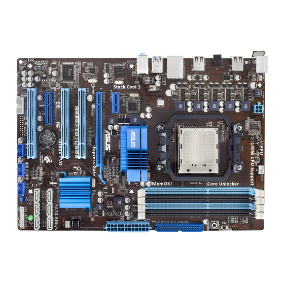
Page 17: Motherboard Layout
1.5.3 Motherboard layout 1.5.4 Layout contents Connectors/Jumpers/Slots Page ATX power connectors (24-pin EATXPWR, 4-pin ATX12V) 1-22 CPU socket AM3 CPU, Chassis and Power Fan connectors (4-pin CPU_FAN, 3-pin CHA_FAN1, 1-24 3-pin PWR_FAN) DDR3 DIMM slots Core Unlocker switch (CORE_UNLOCKER) 1-18 MemOK! switch 1-17 IDE connector (40-1 pin PRI_IDE)
-
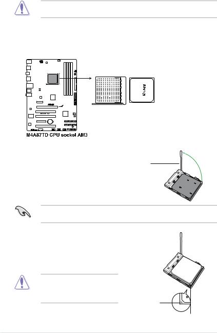
Page 18: Central Processing Unit (Cpu)
Carefully insert the CPU into the socket until it fits in place. The CPU fits only in one correct orientation. DO NOT force the CPU into the socket to prevent bending the pins and damaging the CPU! Small triangle Gold triangle ASUS M4A87TD…
-
Page 19: Installing The Heatsink And Fan
When the CPU is in place, push down the socket lever to secure the CPU. The lever clicks on the side tab to indicate that it is locked. Install a CPU heatsink and fan following the instructions that came with the heatsink package. You can also refer to section 1.6.2 Installing the heatsink and fan for instructions.
-
Page 20: System Memory
(DIMM) sockets. A DDR3 module has the same physical dimensions as a DDR2 DIMM but is notched differently to prevent installation on a DDR2 DIMM socket. DDR3 modules are developed for better performance with less power consumption. The figure illustrates the location of the DDR3 DIMM sockets: ASUS M4A87TD…
-
Page 21: Memory Configurations
• Due to the CPU spec., AMD AM3 100 and 200 series CPUs support up to DDR3 1066MHz. With ASUS design, this motherboard can support up to DDR3 1333MHz. • When overclocking, some AMD CPU models may not support DDR3 1600 or higher frequency DIMMs.
-
Page 22
4GB(2 x 2GB) DS — 8-8-8 1.65 • • • OCZ3FXE1600C7LV6GK 6GB(3 x 2GB) DS — 7-7-7 1.65 • OCZ3X1600LV6GK(XMP) 6GB(3 x 2GB) DS — 8-8-8 1.65 • OCZ3X1600LV6GK(XMP) 6GB(3 x 2GB) DS — 8-8-8 1.65 • ASUS M4A87TD 1-10… -
Page 23
DDR3-1600MHz capability DIMM socket support (Optional) Chip Chip Vendor Part No. Size Timing Voltage Brand 1 DIMM 2 DIMM 4 DIMM Super Talent WB160UX6G8(XMP) 6GB(3 x 2GB) DS — • Super Talent WB160UX6G8(XMP) 6GB(3 x 2GB) DS — • EK Memory EKM324L28BP8-I16(XMP) 4GB(2 x 2GB) DS — •… -
Page 24
6GB(3 x 2GB) DS — 9-9-9-24 1.65 • • Silicon SP001GBLTU1333S01 SS NANYA NT5CB128M8AN-CG — • • Power Silicon SP001GBLTU133S02 SS S-POWER I0YT3E0 • Power Silicon SP002GBLTU133S02 DS S-POWER I0YT3E0 • • • Power UMAX E41302GP0-73BDB DS UMAX U2S24D30TP-13 • • ASUS M4A87TD 1-12… -
Page 25
Dual-channel memory configuration. • C*: Supports four modules inserted into both the blue slots and the black slots as two pairs of Dual-channel memory configuration. Visit the ASUS website for the latest QVL. Chapter 1: Product introduction 1-13… -
Page 26: Installing A Dimm
Simultaneously press the retaining clips outward to unlock the DIMM. Remove the DIMM from the socket. Support the DIMM lightly with your fingers when pressing the retaining clips. The DIMM might get damaged when it flips out with extra force. ASUS M4A87TD 1-14…
-
Page 27: Expansion Slots
Expansion slots In the future, you may need to install expansion cards. The following sub-sections describe the slots and the expansion cards that they support. Unplug the power cord before adding or removing expansion cards. Failure to do so may cause you physical injury and damage motherboard components.
-
Page 28: Jumper
• Due to the chipset behavior, AC power off is required to enable C.P.R. function. You must turn off and on the power supply or unplug and plug the power cord before rebooting the system. ASUS M4A87TD 1-16…
-
Page 29: Onboard Switch
If the installed DIMMs still fail to boot after the whole tuning process, the DRAM_LED lights continuously. Replace the DIMMs with ones recommended in the Memory QVL (Qualified Vendors Lists) in this user manual or on the ASUS website at www.asus.com.
-
Page 30: Onboard Leds
• The system will use the last setting you have made. • If you clear the CMOS or load the BIOS setting defaults, the ASUS Core Unlocker item in the BIOS menu follows the current setting of the Core Unlocker switch.
-
Page 31
Core Unlocker LED The Core Unlocker LED lights when the Core Unclocker switch is turned to Enable. Chapter 1: Product introduction 1-19… -
Page 32: Connectors
USB 2.0 (3.0) ports 1 and 2 (blue). These 4-pin Universal Serial Bus (USB) ports are available for connecting USB 2.0 (3.0) devices. (USB 3.0 only for USB3 Edition) Microphone port (pink). This port connects a microphone. ASUS M4A87TD 1-20…
-
Page 33: Internal Connectors
Refer to the audio configuration table below for the function of the audio ports in 2, 4, 6, or 8-channel configuration. Audio 2, 4, 6, 8-channel configuration Headset Port 4-channel 6-channel 8-channel* 2-channel Light Blue Line In Rear Speaker Out Rear Speaker Out Rear Speaker Out Lime…
-
Page 34
The system may become unstable or may not boot up if the power is inadequate. • If you are uncertain about the minimum power supply requirement for your system, refer to the Recommended Power Supply Wattage Calculator at http://support.asus. com/PowerSupplyCalculator/PSCalculator.aspx?SLanguage=en-us for details. ASUS M4A87TD… -
Page 35
® SB850 Serial ATA Serial ATA 6.0 Gb/s connectors (7-pin SATA 1-6) These connectors are for the Serial ATA 6.0 Gb/s signal cables for Serial ATA hard disk drives and optical disc drives. If you installed Serial ATA hard disk drives, you can create a RAID 0, RAID 1, RAID 5, ®… -
Page 36
• The CPU_FAN connector supports the CPU fan of maximum 2A (24 W) fan power. • Only the CPU_FAN connector support the ASUS Fan Xpert feature. • If you install two VGA cards, we recommend that you plug the rear chassis fan cable to the motherboard connector labeled CHA_FAN1 for better thermal environment. -
Page 37: System Panel Connector
System panel connector (20-8 pin PANEL) This connector supports several chassis-mounted functions. • System power LED (2-pin PLED) This 2-pin connector is for the system power LED. Connect the chassis power LED cable to this connector. The system power LED lights up when you turn on the system power, and blinks when the system is in sleep mode.
-
Page 38
Never connect a 1394 cable to the USB connectors. Doing so will damage the motherboard! The USB 2.0 module is purchased separately. Digital audio connector (4-1 pin SPDIF_OUT) This connector is for an additional Sony/Philips Digital Interface (S/PDIF) ports. The S/PDIF module is purchased separately. ASUS M4A87TD 1-26… -
Page 39
Front panel audio connector (10-1 pin AAFP) This connector is for a chassis-mounted front panel audio I/O module that supports either High Definition Audio or AC`97 audio standard. Connect one end of the front panel audio I/O module cable to this connector. •… -
Page 40: Software Support
ASUS website at www.asus.com for updates. • For detailed software instructions, see the Manual folder in the Support DVD or download the latest software manual from the ASUS website at www.asus.com. To run the Support DVD Place the Support DVD to the optical drive. The DVD automatically displays the Drivers menu if Autorun is enabled in your computer.
-
Page 41: Knowing Bios
Refer to the corresponding sections for details on these utilities. Save a copy of the original motherboard BIOS file to a USB flash drive in case you need to restore the BIOS in the future. Copy the original motherboard BIOS using the ASUS Update utility.
-
Page 42: Asus Update Utility
2.2.1 ASUS Update utility The ASUS Update is a utility that allows you to manage, save, and update the motherboard BIOS in Windows environment. ® • ASUS Update requires an Internet connection either through a network or an Internet Service Provider (ISP).
-
Page 43: Asus Ez Flash 2 Utility
When the correct BIOS file is found, EZ Flash 2 performs the BIOS update process and automatically reboots the system when done. • Only a USB flash disk with FAT 32/16 format and single partition can support the ASUS EZ Flash 2 utility.
-
Page 44: Asus Crashfree Bios 3 Utility
The BIOS file in the motherboard support DVD may be older than the BIOS file published on the ASUS official website. If you want to use the newer BIOS file, download the file at support.asus.com and save it to a USB flash drive.
-
Page 45: Asus Bios Updater
2.2.4 ASUS BIOS Updater The ASUS BIOS Updater allows you to update BIOS in DOS environment. This utility also allows you to copy the current BIOS file that you can use as a backup when the BIOS fails or gets corrupted during the updating process.
-
Page 46: Backing Up The Current Bios
ASUSTek BIOS Updater for DOS V1.00b [09/06/22] FLASH TYPE: MXIC 25L1605A Current ROM Update ROM BOARD: M4A87TD BOARD: Unknown VER: 0206 VER: Unknown DATE: 02/09/2010 DATE: Unknown PATH: BIOS backup is done! Press any key to continue. Note Saving BIOS: ASUS M4A87TD…
-
Page 47: Updating The Bios File
Updating the BIOS file To update the BIOS file using BIOS Updater At the FreeDOS prompt, type bupdater /pc /g and press <Enter>. D:\>bupdater /pc /g The BIOS Updater screen appears as below. ASUSTek BIOS Updater for DOS V1.00b [09/06/22] FLASH TYPE: MXIC 25L1605A Current ROM…
-
Page 48: Bios Setup Program
• The BIOS setup screens shown in this section are for reference purposes only, and may not exactly match what you see on your screen. • Visit the ASUS website at www.asus.com to download the latest BIOS file for this motherboard.
-
Page 49: Bios Menu Screen
• The BIOS setup screens shown in this chapter are for reference purposes only, and may not exactly match what you see on your screen. • Visit the ASUS website at www.asus.com to download the latest BIOS information. Chapter 2: BIOS setup…
-
Page 50: Navigation Keys
Scroll bar fit on the screen. Press the <Up> / <Down> Pop-up window arrow keys or <Page Up> / <Page Down> keys to display the other items on the screen. 2-10 ASUS M4A87TD…
-
Page 51: Main Menu
Main menu When you enter the BIOS Setup program, the Main menu screen appears, giving you an overview of the basic system information. Refer to section 2.3.1 BIOS menu screen for information on the menu screen items and how to navigate through them. BIOS SETUP UTILITY Main Ai Tweaker…
-
Page 52: Storage Configuration
<Enter> to display the submenu. OnChip SATA Channel [Enabled] [Enabled] Enables the onboard channel SATA port. [Disabled] Disables the onboard channel SATA port. The following two items appear only when you set the OnChip SATA Channel item to [Enabled]. 2-12 ASUS M4A87TD…
-
Page 53: System Information
SATA Port1–Port4 [IDE] Allows you to set the SATA configuration. [IDE] Set to [IDE] when you want to use the Serial ATA hard disk drives as Parallel ATA physical storage devices. [RAID] Set to [RAID] when you want to create a RAID configuration from the SATA hard disk drives.
-
Page 54: Ai Tweaker Menu
OC Tuner utility automatically overclocks the frequency and voltage of the CPU and DRAM. Press <Enter> to start auto tuning. It takes around five minutes, and the system will reboot for several times until auto tuning is completed. 2-14 ASUS M4A87TD…
-
Page 55: Ai Overclock Tuner
2.5.3 Ai Overclock Tuner [Auto] Allows you to select the CPU overclocking options to achieve the desired CPU internal frequency. Select any of these preset overclocking configuration options: Manual Allows you to individually set overclocking parameters. Auto Loads the optimal settings for the system. Allows you to select a DRAM O.C.
-
Page 56: Cpu/Nb Frequency
DRAM READ to WRITE Delay [Auto] Configuration options: [Auto] [3 CLK] – [17 CLK] [3 CLK] – [17 CLK] DRAM WRITE to READ Delay(DD) [Auto] Configuration options: [Auto] [2 CLK] – [10 CLK] [2 CLK] – [10 CLK] 2-16 ASUS M4A87TD…
-
Page 57: Dram Driving Configuration
DRAM WRITE to READ Delay(SD) [Auto] Configuration options: [Auto] [4 CLK] [5 CLK] [6 CLK] [7 CLK] [4 CLK] [5 CLK] [6 CLK] [7 CLK] DRAM WRITE to WRITE Timing [Auto] Configuration options: [Auto] [3 CLK] – [10 CLK] DRAM READ to READ Timing [Auto] Configuration options: [Auto] [3 CLK] –…
-
Page 58: Dram Voltage
[Auto] Automatic configuration. [Disabled] Enhances the CPU overclocking ability. [Enabled] Sets to [Enabled] for EMI control. 2.5.17 PCIE Spread Spectrum [Auto] [Auto] Automatic configuration. [Disabled] Enhances the PCIE overclocking ability. [Enabled] Sets to [Enabled] for EMI control. 2-18 ASUS M4A87TD…
-
Page 59: Advanced Menu
[Enabled] Enables the AMD Cool’n’Quiet function. [Disabled] Disables this function. ASUS Core Unlocker [Disabled] [Enabled] Enables the ASUS Core Unlocker to get the full computing power of the processor. [Disabled] Disables this function. C1E Support [Enabled] [Enabled] Enables the C1E support function. This item should be enabled in order to enable the Enhanced Halt Sate.
-
Page 60: Chipset
Onboard Devices Configuration HD Audio Azalia Device [Enabled] Allows you to enable or disable the HD Audio controller. Configuration options: [Disabled] [Enabled] The following item appear only when you set the HD Audio Azalia Device item to [Enabled]. 2-20 ASUS M4A87TD…
-
Page 61: Usb Configuration
Azalia Front Panel [HD] Allows you to set the front panel audio connector (AAFP) mode to legacy AC’97 or high-definition audio depending on the audio standard that the front panel audio module supports. [AC 97] Sets the front panel audio connector (AAFP) mode to legacy AC’97 [HD] Sets the front panel audio connector (AAFP) mode to high definition audio.
-
Page 62: Pcipnp
When set to [Yes] and if you install a Plug and Play operating system, the operating system configures the Plug and Play devices not required for boot. [No] When set to [No], BIOS configures all the devices in the system. 2-22 ASUS M4A87TD…
-
Page 63: Power Menu
Power menu The Power menu items allow you to change the settings for the Advanced Configuration and Power Interface (ACPI) and the Advanced Power Management (APM). Select an item then press <Enter> to display the configuration options. BIOS SETUP UTILITY Main Ai Tweaker Advanced…
-
Page 64: Apm Configuration
2.7.6 Hardware Monitor CPU/MB Temperature [xxxºC/xxxºF] The onboard hardware monitor automatically detects and displays the motherboard and CPU temperatures. Select [Ignored] if you do not wish to display the detected temperatures. 2-24 ASUS M4A87TD…
-
Page 65
CPU Fan / Power Fan / Chassis Fan Speed [xxxxRPM] or [Ignored] The onboard hardware monitor automatically detects and displays the CPU and chassis fan speeds in rotations per minute (RPM). If the fan is not connected to the motherboard, the field shows N/A. -
Page 66: Boot Menu
This allows you to enable or disable the full screen logo display feature. Configuration options: [Disabled] [Enabled] Set this item to [Enabled] to use the ASUS MyLogo 2™ feature. AddOn ROM Display Mode [Force BIOS] Sets the display mode for option ROM. Configuration options: [Force BIOS] [Keep Current] Bootup Num-Lock [On] Allows you to select the power-on state for the NumLock.
-
Page 67: Security
2.8.3 Security The Security menu items allow you to change the system security settings. Select an item then press <Enter> to display the configuration options. Change Supervisor Password Select this item to set or change the supervisor password. The Supervisor Password item on top of the screen shows the default Not Installed.
-
Page 68: Tools Menu
(C)Copyright 1985-2009, American Megatrends, Inc. 2.9.1 ASUS EZ Flash 2 Allows you to run ASUS EZ Flash 2. When you press <OK>, a confirmation message appears. Use the left/right arrow key to select between [Yes] or [No], then press <OK> to confirm your choice.
-
Page 69: Asus O.c. Profile
2.9.3 ASUS O.C. Profile This item allows you to store or load multiple BIOS settings. Add Your CMOS Profile. Allows you to save the current BIOS file to the BIOS Flash. In the Name sub-item, type your profile name and press <Enter>, and then choose a profile number to save your CMOS settings in the Save To sub-item.
-
Page 70: Exit Menu
When you select this option or if you press <F5>, a confirmation window appears. Select OK to load default values. Select Exit & Save Changes or make other changes before saving the values to the non-volatile RAM. 2-30 ASUS M4A87TD…
-
Page 71: Asus Contact Information
+1-812-282-3777 +1-510-608-4555 Web site usa.asus.com Technical Support Telephone +1-812-282-2787 Support fax +1-812-284-0883 Online support support.asus.com ASUS COMPUTER GmbH (Germany and Austria) Address Harkort Str. 21-23, D-40880 Ratingen, Germany +49-2102-959911 Web site www.asus.de Online contact www.asus.de/sales Technical Support Telephone +49-1805-010923* Support Fax…
This manual is also suitable for:
M4a87td
M4A87TD

Регистрация устройства поможет вам управлять его гарантией, получать техническую поддержку и отслеживать статус ремонта.
Регистрация продукта
Руководства пользователя
Версия T6414
5.51 MB
M4A87TD/USB3 user’s manual(Traditional Chinese)
Версия C6414
5.59 MB
M4A87TD/USB3 user’s manual(Simplified Chinese)
Версия E5767
1.22 MB
Turbo Unlocker user’s manual (English)
Версия J5359
4.96 MB
M4A87TD user’s manual (Japanese)
-
Драйверы
33
-
Инструкции по эксплуатации
4
Языки:

ASUS M4A87TD/USB3 инструкция по эксплуатации
(72 страницы)
- Языки:Английский
-
Тип:
PDF -
Размер:
5.29 MB -
Описание:
M4A87TD/USB3 user’s manual (English)
Просмотр

ASUS M4A87TD/USB3 инструкция по эксплуатации
(74 страницы)
- Языки:Французский
-
Тип:
PDF -
Размер:
4.58 MB -
Описание:
M4A87TD/USB3 user’s manual (French)
Просмотр

ASUS M4A87TD/USB3 инструкция по эксплуатации
(72 страницы)
- Языки:Немецкий
-
Тип:
PDF -
Размер:
4.83 MB -
Описание:
M4A87TD/USB3 user’s manual(German)
Просмотр

ASUS M4A87TD/USB3 инструкция по эксплуатации
(75 страниц)
- Языки:Китайский
-
Тип:
PDF -
Размер:
5.99 MB -
Описание:
M4A87TD/USB3 user’s manual(Simplified Chinese)
Просмотр
На NoDevice можно скачать инструкцию по эксплуатации для ASUS M4A87TD/USB3. Руководство пользователя необходимо для ознакомления с правилами установки и эксплуатации ASUS M4A87TD/USB3. Инструкции по использованию помогут правильно настроить ASUS M4A87TD/USB3, исправить ошибки и выявить неполадки.
Asus M4A87TD/USB3 Instruction Manuals and User Guides
We have 1 Instruction Manual and User Guide for M4A87TD/USB3 Asus

Asus M4A87TD/USB3 User Manual, 72 pages
| Recognized languages: | English |
|---|---|
| Pages: | 72 |
| Size: | 5.29 MB |
Document Outline
- M4A87TD specifications summary
- About this guide
- Safety information
- Notices
- Chapter 1 Product introduction
- 1.1 Welcome!
- 1.2 Package contents
- 1.3 Special features
- 1.3.1 Product highlights
- 1.3.2 ASUS Xtreme Design
- 1.4 Before you proceed
- 1.5 Motherboard overview
- 1.5.1 Placement direction
- 1.5.2 Screw holes
- 1.5.3 Motherboard layout
- 1.5.4 Layout contents
- 1.6 Central Processing Unit (CPU)
- 1.6.1 Installing the CPU
- 1.6.2 Installing the heatsink and fan
- 1.7 System memory
- 1.7.1 Overview
- 1.7.2 Memory configurations
- 1.7.3 Installing a DIMM
- 1.7.4 Removing a DIMM
- 1.8 Expansion slots
- 1.8.1 Installing an expansion card
- 1.8.2 Configuring an expansion card
- 1.8.3 PCI slots
- 1.8.4 PCI Express 2.0 x4 / x1 slots
- 1.8.5 PCI Express 2.0 x16 slot
- 1.9 Jumper
- 1.10 Onboard switch
- 1.11 Onboard LEDs
- 1.12 Connectors
- 1.12.1 Rear panel connectors
- 1.12.2 Internal connectors
- 1.13 Software support
- 1.13.1 Installing an operating system
- 1.13.2 Support DVD information
- Chapter 2 BIOS information
- 2.1 Knowing BIOS
- 2.2 Updating BIOS
- 2.2.1 ASUS Update utility
- 2.2.2 ASUS EZ Flash 2 utility
- 2.2.3 ASUS CrashFree BIOS 3 utility
- 2.3 BIOS setup program
- 2.3.1 BIOS menu screen
- 2.3.2 Menu bar
- 2.3.3 Navigation keys
- 2.3.4 Menu items
- 2.3.5 Submenu items
- 2.3.6 Configuration fields
- 2.3.7 General help
- 2.3.8 Pop-up window
- 2.3.9 Scroll bar
- 2.4 Main menu
- 2.4.1 SATA 1–6
- 2.4.2 Storage Configuration
- 2.4.3 System Information
- 2.5 Ai Tweaker menu
- 2.5.1 CPU Level UP [Auto]
- 2.5.2 OC Tuner Utility
- 2.5.3 Ai Overclock Tuner [Auto]
- 2.5.4 CPU Ratio [Auto]
- 2.5.5 DRAM Frequency [Auto]
- 2.5.6 CPU/NB Frequency [Auto]
- 2.5.7 HT Link Speed [Auto]
- 2.5.8 DRAM Timing Configuration
- 2.5.9 DRAM Driving Configuration
- 2.5.10 CPU & NB Voltage Mode [Offset]
- 2.5.11 DRAM Voltage [Auto]
- 2.5.12 HT Voltage [Auto]
- 2.5.13 NB Voltage [Auto]
- 2.5.14 CPU Load-Line Calibration [Auto]
- 2.5.15 CPU/NB Load-Line Calibration [Auto]
- 2.5.16 CPU Spread Spectrum [Auto]
- 2.5.17 PCIE Spread Spectrum [Auto]
- 2.6 Advanced menu
- 2.6.1 CPU Configuration
- 2.6.2 Chipset
- 2.6.3 Onboard Devices Configuration
- 2.6.4 USB Configuration
- 2.6.5 PCIPnP
- 2.7 Power menu
- 2.7.1 Suspend Mode [Auto]
- 2.7.2 Repost Video on S3 Resume [No]
- 2.7.3 ACPI 2.0 Support [Enabled]
- 2.7.4 ACPI APIC support [Enabled]
- 2.7.5 APM Configuration
- 2.7.6 Hardware Monitor
- 2.8 Boot menu
- 2.8.1 Boot Device Priority
- 2.8.2 Boot Settings Configuration
- 2.8.3 Security
- 2.9 Tools menu
- 2.9.1 ASUS EZ Flash 2
- 2.9.2 Express Gate [Auto]
- 2.9.3 ASUS O.C. Profile
- 2.9.4 AI NET 2
- 2.10 Exit menu
Read manual
![]()

E5359
First Edition V1
March 2010
Copyright © 2010 ASUSTeK COMPUTER INC. All Rights Reserved.
No part of this manual, including the products and software described in it, may be reproduced, transmitted, transcribed, stored in a retrieval system, or translated into any language in any form or by any means, except documentation kept by the purchaser for backup purposes, without the express written permission of ASUSTeK COMPUTER INC. (“ASUS”).
Product warranty or service will not be extended if: (1) the product is repaired, modified or altered, unless such repair, modification of alteration is authorized in writing by ASUS; or (2) the serial number of the product is defaced or missing.
ASUS PROVIDES THIS MANUAL “AS IS” WITHOUT WARRANTY OF ANY KIND, EITHER EXPRESS OR IMPLIED, INCLUDING BUT NOT LIMITED TO THE IMPLIED WARRANTIES OR CONDITIONS OF MERCHANTABILITY OR FITNESS FOR A PARTICULAR PURPOSE. IN NO EVENT SHALL ASUS, ITS DIRECTORS, OFFICERS, EMPLOYEES OR AGENTS BE LIABLE FOR ANY INDIRECT, SPECIAL, INCIDENTAL, OR CONSEQUENTIAL DAMAGES (INCLUDING DAMAGES FOR LOSS OF PROFITS, LOSS OF BUSINESS, LOSS OF USE OR DATA, INTERRUPTION OF BUSINESS AND THE LIKE), EVEN IF ASUS HAS BEEN ADVISED OF THE POSSIBILITY OF SUCH DAMAGES ARISING FROM ANY DEFECT OR ERROR IN THIS MANUAL OR PRODUCT.
SPECIFICATIONS AND INFORMATION CONTAINED IN THIS MANUAL ARE FURNISHED FOR INFORMATIONAL USE ONLY, AND ARE SUBJECT TO CHANGE AT ANY TIME WITHOUT NOTICE, AND SHOULD NOT BE CONSTRUED AS A COMMITMENT BY ASUS. ASUS ASSUMES NO RESPONSIBILITY OR LIABILITY FOR ANY ERRORS OR INACCURACIES THAT MAY APPEAR IN THIS MANUAL, INCLUDING THE PRODUCTS AND SOFTWARE DESCRIBED IN IT.
Products and corporate names appearing in this manual may or may not be registered trademarks or copyrights of their respective companies, and are used only for identification or explanation and to the owners’ benefit, without intent to infringe.
Offer to Provide Source Code of Certain Software
This product may contain copyrighted software that is licensed under the General Public License (“GPL”) and under the Lesser General Public License Version (“LGPL”). The GPL and LGPL licensed code in this product is distributed without any warranty. Copies of these licenses are included in this product.
You may obtain the complete corresponding source code (as defined in the GPL) for the GPL Software, and/or the complete corresponding source code of the LGPL Software (with the complete machinereadable “work that uses the Library”) for a period of three years after our last shipment of the product including the GPL Software and/or LGPL Software, which will be no earlier than December 1, 2011, either
(1)for free by downloading it from http://support.asus.com/download;
or
(2)for the cost of reproduction and shipment, which is dependent on the preferred carrier and the location where you want to have it shipped to, by sending a request to:
ASUSTeK Computer Inc.
Legal Compliance Dept. 15 Li Te Rd.,
Beitou, Taipei 112 Taiwan
In your request please provide the name, model number and version, as stated in the About Box of the product for which you wish to obtain the corresponding source code and your contact details so that we can coordinate the terms and cost of shipment with you.
The source code will be distributed WITHOUT ANY WARRANTY and licensed under the same license as the corresponding binary/object code.
This offer is valid to anyone in receipt of this information.
ASUSTeK is eager to duly provide complete source code as required under various Free Open Source Software licenses. If however you encounter any problems in obtaining the full corresponding source code we would be much obliged if you give us a notification to the email address gpl@asus.com, stating the product and describing the problem (please do NOT send large attachments such as source code archives etc to this email address).
ii

Contents
|
Notices…………………………………………………………………………………………… |
vi |
|
Safety information………………………………………………………………………….. |
vii |
|
About this guide…………………………………………………………………………….. |
vii |
|
M4A87TD specifications summary…………………………………………………… |
ix |
|
Chapter 1 |
Product introduction |
||
|
1.1 |
Welcome!…………………………………………………………………………… |
1-1 |
|
|
1.2 |
Package contents………………………………………………………………. |
1-1 |
|
|
1.3 |
Special features…………………………………………………………………. |
1-1 |
|
|
1.3.1 |
Product highlights …………………………………………………… |
1-1 |
|
|
1.3.2 |
ASUS Xtreme Design ……………………………………………… |
1-2 |
|
|
1.4 |
Before you proceed……………………………………………………………. |
1-4 |
|
|
1.5 |
Motherboard overview……………………………………………………….. |
1-4 |
|
|
1.5.1 |
Placement direction ………………………………………………… |
1-4 |
|
|
1.5.2 |
Screw holes …………………………………………………………… |
1-4 |
|
|
1.5.3 |
Motherboard layout …………………………………………………. |
1-5 |
|
|
1.5.4 |
Layout contents . …………………………………………………….. |
1-5 |
|
|
1.6 |
Central Processing Unit (CPU)……………………………………………. |
1-6 |
|
|
1.6.1 |
Installing the CPU …………………………………………………… |
1-6 |
|
|
1.6.2 |
Installing the heatsink and fan ………………………………….. |
1-7 |
|
|
1.7 |
System memory…………………………………………………………………. |
1-8 |
|
|
1.7.1 |
Overview ……………………………………………………………….. |
1-8 |
|
|
1.7.2 |
Memory configurations . …………………………………………… |
1-9 |
|
|
1.7.3 |
Installing a DIMM ………………………………………………….. |
1-14 |
|
|
1.7.4 |
Removing a DIMM ………………………………………………… |
1-14 |
|
|
1.8 |
Expansion slots……………………………………………………………….. |
1-15 |
|
|
1.8.1 |
Installing an expansion card …………………………………… |
1-15 |
|
|
1.8.2 |
Configuring an expansion card ……………………………….. |
1-15 |
|
|
1.8.3 |
PCI slots . …………………………………………………………….. |
1-15 |
|
|
1.8.4 |
PCI Express 2.0 x4 / x1 slots ………………………………….. |
1-15 |
|
|
1.8.5 |
PCI Express 2.0 x16 slot . ………………………………………. |
1-15 |
|
|
1.9 |
Jumper |
…………………………………………………………………………….. |
1-16 |
|
1.10 |
Onboard …………………………………………………………………switch |
1-17 |
|
|
1.11 |
Onboard …………………………………………………………………..LEDs |
1-18 |
|
|
1.12 |
Connectors………………………………………………………………………. |
1-20 |
|
|
1.12.1 ………………………………………….. |
Rear panel connectors |
1-20 |
iii

Contents
|
1.12.2 |
Internal connectors……………………………………………….. |
1-21 |
|
1.13 Software support……………………………………………………………… |
1-28 |
|
|
1.13.1 Installing an operating system………………………………… |
1-28 |
|
|
1.13.2 |
Support DVD information……………………………………….. |
1-28 |
|
Chapter 2 |
BIOS information |
||
|
2.1 |
Knowing BIOS……………………………………………………………………. |
2-1 |
|
|
2.2 |
Updating BIOS…………………………………………………………………… |
2-1 |
|
|
2.2.1 |
ASUS Update utility………………………………………………… |
2-2 |
|
|
2.2.2 |
ASUS EZ Flash 2 utility.………………………………………….. |
2-3 |
|
|
2.2.3 |
ASUS CrashFree BIOS 3 utility………………………………… |
2-4 |
|
|
2.3 |
BIOS setup program…………………………………………………………… |
2-8 |
|
|
2.3.1 |
BIOS menu screen.………………………………………………… |
2-9 |
|
|
2.3.2 |
Menu bar………………………………………………………………. |
2-9 |
|
|
2.3.3 |
Navigation keys.…………………………………………………… |
2-10 |
|
|
2.3.4 |
Menu items………………………………………………………….. |
2-10 |
|
|
2.3.5 |
Submenu items…………………………………………………….. |
2-10 |
|
|
2.3.6 |
Configuration fields……………………………………………….. |
2-10 |
|
|
2.3.7 |
General help………………………………………………………… |
2-10 |
|
|
2.3.8 |
Pop-up window…………………………………………………….. |
2-10 |
|
|
2.3.9 |
Scroll bar…………………………………………………………….. |
2-10 |
|
|
2.4 |
Main menu……………………………………………………………………….. |
2-11 |
|
|
2.4.1 |
SATA 1–6……………………………………………………………… |
2-11 |
|
|
2.4.2 |
Storage Configuration……………………………………………. |
2-12 |
|
|
2.4.3 |
System Information……………………………………………….. |
2-13 |
|
|
2.5 |
Ai Tweaker menu……………………………………………………………… |
2-14 |
|
|
2.5.1 |
CPU Level UP ……………………………………………………… |
2-14 |
|
|
2.5.2 |
OC Tuner Utility.…………………………………………………… |
2-14 |
|
|
2.5.3 |
Ai Overclock Tuner .……………………………………………… |
2-15 |
|
|
2.5.4 |
CPU Ratio …………………………………………………………… |
2-15 |
|
|
2.5.5 |
DRAM Frequency ………………………………………………… |
2-15 |
|
|
2.5.6 |
CPU/NB Frequency ……………………………………………… |
2-16 |
|
|
2.5.7 |
HT Link Speed …………………………………………………….. |
2-16 |
|
|
2.5.8 |
DRAM Timing Configuration…………………………………… |
2-16 |
|
|
2.5.9 |
DRAM Driving Configuration………………………………….. |
2-17 |
|
|
2.5.10 |
CPU & NB Voltage Mode……………………………………….. |
2-17 |
iv

Contents
|
2.5.11 |
DRAM Voltage …………………………………………………….. |
2-18 |
|
|
2.5.12 |
HT Voltage ………………………………………………………….. |
2-18 |
|
|
2.5.13 |
NB Voltage ………………………………………………………….. |
2-18 |
|
|
2.5.14 |
CPU Load-Line Calibration ……………………………………. |
2-18 |
|
|
2.5.15 |
CPU/NB Load-Line Calibration ………………………………. |
2-18 |
|
|
2.5.16 |
CPU Spread Spectrum …………………………………………. |
2-18 |
|
|
2.5.17 |
PCIE Spread Spectrum .……………………………………….. |
2-18 |
|
|
2.6 |
Advanced menu……………………………………………………………….. |
2-19 |
|
|
2.6.1 |
CPU Configuration………………………………………………… |
2-19 |
|
|
2.6.2 |
Chipset……………………………………………………………….. |
2-20 |
|
|
2.6.3 |
Onboard Devices Configuration……………………………… |
2-20 |
|
|
2.6.4 |
USB Configuration………………………………………………… |
2-21 |
|
|
2.6.5 |
PCIPnP……………………………………………………………….. |
2-22 |
|
|
2.7 |
Power menu…………………………………………………………………….. |
2-23 |
|
|
2.7.1 |
Suspend Mode ……………………………………………………. |
2-23 |
|
|
2.7.2 |
Repost Video on S3 Resume.………………………………… |
2-23 |
|
|
2.7.3 |
ACPI 2.0 Support………………………………………………….. |
2-23 |
|
|
2.7.4 |
ACPI APIC support……………………………………………….. |
2-23 |
|
|
2.7.5 |
APM Configuration……………………………………………….. |
2-24 |
|
|
2.7.6 |
Hardware Monitor…………………………………………………. |
2-24 |
|
|
2.8 |
Boot menu……………………………………………………………………….. |
2-26 |
|
|
2.8.1 |
Boot Device Priority………………………………………………. |
2-26 |
|
|
2.8.2 |
Boot Settings Configuration……………………………………. |
2-26 |
|
|
2.8.3 |
Security……………………………………………………………….. |
2-27 |
|
|
2.9 |
Tools menu………………………………………………………………………. |
2-28 |
|
|
2.9.1 |
ASUS EZ Flash 2…………………………………………………. |
2-28 |
|
|
2.9.2 |
Express Gate ………………………………………………………. |
2-28 |
|
|
2.9.3 |
ASUS O.C. Profile.……………………………………………….. |
2-29 |
|
|
2.9.4 |
AI NET 2……………………………………………………………… |
2-29 |
|
|
2.10 |
Exit menu…………………………………………………………………………. |
2-30 |
Notices
Federal Communications Commission Statement
This device complies with Part 15 of the FCC Rules. Operation is subject to the following two conditions:
•This device may not cause harmful interference, and
•This device must accept any interference received including interference that may cause undesired operation.
This equipment has been tested and found to comply with the limits for a Class B digital device, pursuant to Part 15 of the FCC Rules. These limits are designed to provide reasonable protection against harmful interference in a residential installation. This equipment generates, uses and can radiate radio frequency energy and, if not installed and used in accordance with manufacturer’s instructions, may cause harmful interference to radio communications. However, there is no guarantee that interference will not occur in a particular installation. If this equipment does cause harmful interference to radio or
television reception, which can be determined by turning the equipment off and on, the user is encouraged to try to correct the interference by one or more of the following measures:
•Reorient or relocate the receiving antenna.
•Increase the separation between the equipment and receiver.
•Connect the equipment to an outlet on a circuit different from that to which the receiver is connected.
•Consult the dealer or an experienced radio/TV technician for help.
The use of shielded cables for connection of the monitor to the graphics card is required to assure compliance with FCC regulations. Changes or modifications to this unit not expressly approved by the party responsible for compliance could void the user’s authority to operate this equipment.
Canadian Department of Communications Statement
This digital apparatus does not exceed the Class B limits for radio noise emissions from digital apparatus set out in the Radio Interference Regulations of the Canadian Department of Communications.
This class B digital apparatus complies with Canadian ICES-003.
REACH
Complying with the REACH (Registration, Evaluation, Authorisation, and Restriction of Chemicals) regulatory framework, we published the chemical substances in our products at ASUS REACH website at http://green.asus.com/english/REACH.htm.
DO NOT throw the motherboard in municipal waste. This product has been designed to enable proper reuse of parts and recycling. This symbol of the crossed out wheeled bin indicates that the product (electrical and electronic equipment) should not be placed in municipal waste. Check local regulations for disposal of electronic products.
DO NOT throw the mercury-containing button cell battery in municipal waste. This symbol of the crossed out wheeled bin indicates that the battery should not be placed in municipal waste.
vi

Safety information
Electrical safety
•To prevent electrical shock hazard, disconnect the power cable from the electrical outlet before relocating the system.
•When adding or removing devices to or from the system, ensure that the power cables for the devices are unplugged before the signal cables are connected. If possible, disconnect all power cables from the existing system before you add a device.
•Before connecting or removing signal cables from the motherboard, ensure that all power cables are unplugged.
•Seek professional assistance before using an adapter or extension cord. These devices could interrupt the grounding circuit.
•Ensure that your power supply is set to the correct voltage in your area. If you are not sure about the voltage of the electrical outlet you are using, contact your local power company.
•If the power supply is broken, do not try to fix it by yourself. Contact a qualified service technician or your retailer.
Operation safety
•Before installing the motherboard and adding devices on it, carefully read all the manuals that came with the package.
•Before using the product, ensure all cables are correctly connected and the power cables are not damaged. If you detect any damage, contact your dealer immediately.
•To avoid short circuits, keep paper clips, screws, and staples away from connectors, slots, sockets and circuitry.
•Avoid dust, humidity, and temperature extremes. Do not place the product in any area where it may become wet.
•Place the product on a stable surface.
•If you encounter technical problems with the product, contact a qualified service technician or your retailer.
About this guide
This user guide contains the information you need when installing and configuring the motherboard.
How this guide is organized
This guide contains the following parts:
•Chapter 1: Product introduction
This chapter describes the features of the motherboard and the new technology it supports.
•Chapter 2: BIOS setup
This chapter tells how to change system settings through the BIOS Setup menus. Detailed descriptions of the BIOS parameters are also provided.
vii

Conventions used in this guide
To ensure that you perform certain tasks properly, take note of the following symbols used throughout this manual.
DANGER/WARNING: Information to prevent injury to yourself when trying to complete a task.
CAUTION: Information to prevent damage to the components
when trying to complete a task.
IMPORTANT: Instructions that you MUST follow to complete a task.
NOTE: Tips and additional information to help you complete a task.
Where to find more information
Refer to the following sources for additional information and for product and software updates.
1.ASUS websites
The ASUS website provides updated information on ASUS hardware and software products. Refer to the ASUS contact information.
2.Optional documentation
Your product package may include optional documentation, such as warranty flyers, that may have been added by your dealer. These documents are not part of the standard package.
Typography
|
Bold text |
Indicates a menu or an item to select. |
|
Italics |
Used to emphasize a word or a phrase. |
|
<Key> |
Keys enclosed in the less-than and greater-than sign means |
|
that you must press the enclosed key. |
|
|
Example: <Enter> means that you must press the Enter or |
|
|
Return key. |
|
|
<Key1>+<Key2>+<Key3> |
If you must press two or more keys simultaneously, the key |
|
names are linked with a plus sign (+). |
|
|
Example: <Ctrl>+<Alt>+<D> |
viii

M4A87TD specifications summary
|
CPU |
AMD® Socket AM3 for AMD® Phenom™ II / Athlon™ II / |
|
Sempron™ 100 Series Processors |
|
|
AMD® 140W CPU Support |
|
|
AMD® Cool ‘n’ Quiet™ 2.0 Technology (by CPU type) |
|
|
Supports 45nm CPU |
|
|
Chipset |
AMD® 870 / SB850 |
|
System bus |
Up to 5200 MT/s; HyperTransport™ 3.0 interface |
|
Memory |
4 x DIMM, max. 16 GB, DDR3 2000(O.C.)/ 1600 / 1333 / |
|
1066 MHz ECC / non-ECC, un-buffered memory |
|
|
Dual-channel memory architecture |
|
|
DDR3 Memory Ultra Low Voltage support |
|
|
* Due to the CPU spec., AMD AM3 100 and 200 series |
|
|
CPUs support up to DDR3 1066MHz. With ASUS design, |
|
|
this motherboard can support up to DDR3 1333MHz. |
|
|
** Due to OS limitation, when installing total memory of 4GB |
|
|
capacity or more, Windows® 32-bit operating system may |
|
|
only recognize less than 3 GB. Install a 64-bit Windows® |
|
|
OS when you want to install 4GB or more memory on the |
|
|
motherboard. |
|
|
*** Refer to www.asus.com or this user manual for the |
|
|
Memory QVL (Qualified Vendors Lists) |
|
|
Expansion slots |
1 x PCIe 2.0 x16 slot |
|
1 x PCIe 2.0 x4 slot |
|
|
1 x PCIe 2.0 x1 slot |
|
|
3 x PCI slots |
|
|
Storage |
SB850 chipet: |
|
— 6 x SATA 6Gb/s supporting RAID 0, 1, 5, and 10 |
|
|
JMicron® JMB368 SATA & PATA controllers: |
|
|
— 1 x UltraDMA 133/100 for up to 2 PATA devices |
|
|
LAN |
RTL8111E PCIe Gigabit LAN controller featuring AI NET 2 |
|
Audio |
VIA® VT1818 8-channel High Definition Audio CODEC |
|
— Blu-ray disc audio layer Content Protection |
|
|
— Supports Jack-Detection, Multi-Streaming and Front |
|
|
Panel Jack-Retasking |
|
|
— Optical S/PDIF Out port at back I/O |
|
|
— ASUS Noise Filter |
|
|
USB |
NEC USB3 controller: (only for USB3 Edition) |
|
— 2 x USB 3.0 ports (blue at back panel) |
|
|
SB850 chipset: |
|
|
— 14(12) x USB 2.0 ports (6 ports at midboard; 8(6) ports at |
|
|
back panel) (12 ports for USB3 Edition) |
|
|
(continued on the next page) |
ix

M4A87TD specifications summary
|
ASUS Unique Features |
ASUS Xtreme Design |
|
|
ASUS Hybrid Processor—TurboV EVO |
||
|
— Auto Tuning, TurboV, Turbo Key, CPU Level UP |
||
|
ASUS Hybrid Switch |
||
|
— Core Unlocker |
||
|
ASUS Hybrid OS—Express Gate |
||
|
ASUS Exclusive Feature |
||
|
— |
MemOK! |
|
|
— |
ASUS EPU |
|
|
ASUS Quiet Thermal Solution |
||
|
— ASUS Fanless Design: heat sink solution |
||
|
— |
ASUS Fan Xpert |
|
|
ASUS EZ DIY |
||
|
— ASUS CrashFree BIOS 3 |
||
|
— |
ASUS O.C. Profile |
|
|
— ASUS EZ Flash 2 |
||
|
— |
ASUS MyLogo 2™ |
|
|
— Multi-language BIOS |
||
|
ASUS Exclusive |
Precision Tweaker 2 |
|
|
Overclocking Features |
— |
vCore: Adjustable CPU voltage at 0.003125V |
|
increment |
||
|
— vDDNB: Adjustable CPU NB voltage at 0.003125V |
||
|
increment |
||
|
— vNB: Adjustable North Bridge voltage at 0.00625V |
||
|
increment |
||
|
— vHT bus: Adjustable PCH voltage at 0.00625V |
||
|
increment |
||
|
— vDRAM Bus: Adjustable DRAM voltage at 0.00625V |
||
|
increment |
SFS (Stepless Frequency Selection):
—Internal Base Clock tuning from 100MHz up to 600MHz at 1MHz increment
—PCIe frequency tuning from 100MHz to 150MHz at 1MHz increment
Overclocking protection:
— ASUS C.P.R. (CPU Parameter Recall)
(continued on the next page)
![]()
M4A87TD specifications summary
Internal I/O connectors
Rear panel I/O ports
BIOS features
Manageability
Support DVD contents
Form factor
3 x USB connectors support additional 6 USB ports
1 x IDE connector
1 x S/PDIF out header
1 x CPU fan connector
1 x chassis fan connector (3-pin)
1 x power fan connector
1 x COM connector
1 x Clear CMOS jumper
6 x SATA 6Gb/s connectors
1 x system panel connector
1 x high definition front panel audio connector
1 x 24-pin ATX power connector
1 x 4-pin ATX 12V power connector
1 x Core Unlocker switch
1 x MemOK! button
1 x PS/2 keyboard port (purple)
1 x PS/2 mouse port (green)
1 x Optical S/PDIF Out port
1 x LAN (RJ-45) port
2 x USB 3.0/2.0 ports (blue)
(USB 3.0 only for USB3 Edition)
8 x USB 2.0/1.1 ports (6 ports for USB3 Edition) 8-channel audio I/O ports
8 Mb Flash ROM, SPI, AMI BIOS, PnP, DMI 2.0, WfM2.0, SM BIOS 2.5, ACPI 2.0a, Multi-language BIOS, ASUS EZ Flash 2, ASUS CrashFree BIOS 3
WfM 2.0, DMI 2.0, WOL by PME, WOR by PME, PXE
Drivers
ASUS Utilities
ASUS Update
Anti-virus software (OEM version)
ATX form factor: 12 in x 8.4 in (30.5 cm x 21.3 cm)
* Specifications are subject to change without notice.
xi

xii
Chapter 1
Product introduction
1.1Welcome!
Thank you for buying an ASUS® M4A87TD motherboard!
The motherboard delivers a host of new features and latest technologies, making it another standout in the long line of ASUS quality motherboards!
Before you start installing the motherboard, and hardware devices on it, check the items in your package with the list below.
1.2Package contents
Check your motherboard package for the following items.
|
Motherboard |
ASUS M4A87TD motherboard |
||
|
Cables |
1 x Ultra DMA 133/100/66 cable |
||
|
2 x Serial ATA 3.0Gb/s cable |
|||
|
1 x Serial ATA 6.0Gb/s cable |
|||
|
1 x 2 in 1 Q-connector |
|||
|
Accessories |
1 x IO shield |
||
|
Application DVD |
ASUS motherboard support DVD |
||
|
Documentations |
User manual |
||
If any of the above items is damaged or missing, contact your retailer.
1.3Special features
1.3.1Product highlights
AMD® Socket AM3; Phenom™ II / Athlon™ II / Sempron™ 100 Series Processors
This motherboard supports AMD® AM3 multi-core processors with unique L3 cache and delivers better overclocking capabilities with less power consumption. It features dual-channel DDR3 1333 memory support and accelerates data transfer rate up to 5200MT/s via HyperTransort™ 3.0 based system bus. This motherboard also supports AMD® CPUs in the new 45nm manufacturing process.
|
Chapter 1: Product introduction |
1-1 |
AMD® 870 chipset
AMD® 870 Chipset is designed to support up to 5200MT/s HyperTransport™ 3.0 (HT 3.0) interface speed and PCI Express™ 2.0 x16 graphics. It is optimized with AMD®’s latest AM3 and multi-core CPUs to provide excellent system performance and overclocking capabilities.
DDR3 2000(O.C.) / 1600 / 1333 / 1066 support
This motherboard supports DDR3 memory that features faster data transfer rates of 2000(O.C.)/1600/1333/1066 MHz to meet the higher bandwidth requirements of the latest 3D graphics, multimedia, and Internet applications. The dual-channel DDR3 architecture enlarges the bandwidth of your system memory to boost system performance.
True SATA 6Gb/s Support
Supporting next-generation Serial ATA (SATA) storage interface, this motherboard delivers up to 6.0Gb/s data transfer rates. Additionally, get enhanced scalability, faster data retrieval, double the bandwidth of current bus systems.
True USB 3.0 Support (Only for USB3 Edition)
Experience ultra-fast data transfers at 4.8Gbps with USB 3.0—the latest connectivity standard. Built to connect easily with next generation components and peripherals, USB 3.0 transfers data 10X faster and is also backward compatible with USB 2.0 components.
1.3.2 ASUS Xtreme Design
Hybrid Switch
Core Unlocker
1 2
ASUS Core Unlocker simplifies the activation of a latent AMD® CPU—with just a simple switch. Enjoy an instant performance boost by simply unlocking the extra cores, without performing complicated BIOS changes.
MemOK!
MemOK! Quickly ensures memory boot compatibility. This remarkable memory rescue tool requires a mere push of a button to patch memory issues. MemOK! Determines failsafe settings and dramatically improves your system boot success. Get your system up and running in no time!
ASUS Power Solutions
ASUS EPU
The ASUS EPU (Energy Processing Unit) provides total system power management by detecting current PC loadings and intelligently moderating power usage for critical PC components in real-time–helping save power and money!
ASUS Hybrid OS
ASUS Express Gate
Express Gate is an ASUS exclusive OS that provides you with quick access to the Internet and key applications before entering the Windows® OS.
ASUS Quiet Thermal Solutions
Fan Xpert
ASUS Fan Xpert intelligently allows you to adjust the CPU fan speed according to different ambient temperatures caused by different climate conditions in different geographic regions and your PC’s loading.
The built-in variety of useful profiles offer flexible controls of fan speed to achieve a quiet and cool environment.
ASUS Intelligent Overclocking Tools
TurboV EVO
Whether novice or enthusiast, TurboV EVO satisfies overclockers of any level. Intelligently push systems to the fastest, stable clock speeds with Auto-Tuning. Turbo Key boosts performance with a simple touch, while TurboV offers additional advanced options for breaking those records!
CPU Level UP
Ever wish that you could have a more expansive CPU? Upgrade your CPU at no additional cost with CPU Level UP! Simply pick the processor you want to OC to, and the motherboard will do the rest! See the new CPU speed and enjoy that performance instantly. Overclocking is never as easy as this.
|
Chapter 1: Product introduction |
1-3 |

1.4Before you proceed
Take note of the following precautions before you install motherboard components or change any motherboard settings.
• Unplug the power cord from the wall socket before touching any component.
•Before handling components, use a grounded wrist strap or touch a safely grounded object or a metal object, such as the power supply case, to avoid damaging them due to static electricity.
•Hold components by the edges to avoid touching the ICs on them.
•Whenever you uninstall any component, place it on a grounded antistatic pad or in the bag that came with the component.
•Before you install or remove any component, switch off the ATX power supply and detach its power cord. Failure to do so may cause severe damage to the motherboard, peripherals, or components.
1.5Motherboard overview
1.5.1Placement direction
When installing the motherboard, ensure that you place it into the chassis in the correct orientation. The edge with external ports goes to the rear part of the chassis as indicated in the image below.
1.5.2Screw holes
Place six (6) screws into the holes indicated by circles to secure the motherboard to the chassis.
Do not overtighten the screws! Doing so can damage the motherboard.
Place this side towards the rear of the chassis. 

1.5.3Motherboard layout
1.5.4Layout contents
|
Connectors/Jumpers/Slots |
Page |
|
|
1. |
ATX power connectors (24-pin EATXPWR, 4-pin ATX12V) |
1-22 |
|
2. |
CPU socket AM3 |
1-6 |
|
3. |
CPU, Chassis and Power Fan connectors (4-pin CPU_FAN, 3-pin CHA_FAN1, |
1-24 |
|
3-pin PWR_FAN) |
||
|
4. |
DDR3 DIMM slots |
1-9 |
|
5. |
Core Unlocker switch (CORE_UNLOCKER) |
1-18 |
|
6. |
MemOK! switch |
1-17 |
|
7. |
IDE connector (40-1 pin PRI_IDE) |
1-21 |
|
8. |
Serial ATA 6G/b connectors (7-pin SATA1-6) |
1-23 |
|
9. |
Standby power LED (SB_PWR) |
1-18 |
|
10. |
System panel connector (20-8 pin PANEL) |
1-25 |
|
11. |
Clear RTC RAM (CLRTC) |
1-16 |
|
12. |
USB connectors (10-1 pin USB78, USB910, USB1112) |
1-26 |
|
13. |
Serial port connector (10-1 pin COM1) |
1-27 |
|
14. |
Digital audio connector (4-1 pin SPDIF_OUT) |
1-26 |
|
15. |
Front panel audio connector (10-1 pin AAFP) |
1-27 |
|
Chapter 1: Product introduction |
1-5 |
1.6Central Processing Unit (CPU)
The motherboard comes with an AM3 socket designed for AMD® Phenom™ II / Athlon™ II / Sempron™ 100 Series Processors.
The CPU socket is not compatible with AMD® Opteron™ processors. Do not install an Opteron™ processor on this motherboard.
1.6.1Installing the CPU
To install a CPU:
1.Locate the CPU socket on the motherboard.
2. Press the lever sideways to unlock
the socket, then lift it up to a Socket lever 90°–100° angle.
Ensure that the socket lever is lifted up to 90°–100° angle, otherwise the CPU will not fit in completely.
3.Position the CPU above the socket such that the CPU corner with the gold triangle matches the socket corner with a small triangle.
4. Carefully insert the CPU into the socket until it fits in place.
The CPU fits only in one correct orientation. DO NOT force the CPU into the socket to prevent bending the pins
and damaging the CPU!
Small triangle

5.When the CPU is in place, push down the socket lever to secure the CPU. The lever clicks on the side
tab to indicate that it is locked.
6. Install a CPU heatsink and fan following the instructions that came with the heatsink package. You can also refer to section 1.6.2 Installing the heatsink and fan for instructions.
7. Connect the CPU fan cable to the CPU_FAN connector on the motherboard.
Do not forget to connect the CPU fan connector! Hardware monitoring errors can occur if you fail to plug this connector.
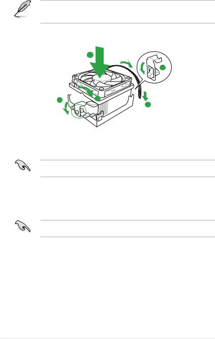
1.6.2Installing the heatsink and fan
Ensure that you use only AMD-certified heatsink and fan assembly.
To install the CPU heatsink and fan:
1.Place the heatsink on top of the installed CPU, making sure that the heatsink fits properly on the retention module base.
• The retention module base is already installed on the motherboard upon purchase.
• You do not have to remove the retention module base when installing the CPU or installing other motherboard components.
•If you purchased a separate CPU heatsink and fan assembly, ensure that a Thermal Interface Material is properly applied to the CPU heatsink or CPU before you install the heatsink and fan assembly.
CPU Fan
CPU Heatsink
Retention bracket
Retention Module Base
Retention bracket lock
|
Chapter 1: Product introduction |
1-7 |
Your boxed CPU heatsink and fan assembly should come with installation instructions for the CPU, heatsink, and the retention mechanism. If the instructions in this section do not match the CPU documentation, follow the latter.
2.Attach one end of the retention bracket to the retention module base.
1
2
3 4
4 
 5
5
3.Align the other end of the retention bracket to the retention module base. A clicking sound denotes that the retention bracket is in place.
Ensure that the fan and heatsink assembly perfectly fits the retention mechanism module base, otherwise you cannot snap the retention bracket in place.
4.Push down the retention bracket lock on the retention mechanism to secure the heatsink and fan to the module base.
5.When the fan and heatsink assembly is in place, connect the CPU fan cable to the connector on the motherboard labeled CPU_FAN.
Do not forget to connect the CPU fan connector! Hardware monitoring errors can occur if you fail to plug this connector.
1.7System memory
1.7.1Overview
The motherboard comes with four Double Data Rate 3 (DDR3) Dual Inline Memory Modules (DIMM) sockets. A DDR3 module has the same physical dimensions as a DDR2 DIMM but is notched differently to prevent installation on a DDR2 DIMM socket. DDR3 modules are developed for better performance with less power consumption. The figure illustrates the location of the DDR3 DIMM sockets:
![]()
Channel Sockets
Channel A DIMM_A1 and DIMM_B1
Channel B DIMM_A2 and DIMM_B2
1.7.2Memory configurations
You may install 512MB, 1GB, 2GB and 4GB unbuffered ECC and non-ECC DDR3 DIMMs into the DIMM sockets.
• You may install varying memory sizes in Channel A and Channel B. The system maps the total size of the lower-sized channel for the dual-channel configuration. Any excess memory from the higher-sized channel is then mapped for single-channel operation.
•We recommend that you install the memory modules from the blue slots for better overclocking capability.
•Always install DIMMs with the same CAS latency. For optimum compatibility, we recommend that you obtain memory modules from the same vendor.
•Due to the CPU spec., AMD AM3 100 and 200 series CPUs support up to DDR3
1066MHz. With ASUS design, this motherboard can support up to DDR3 1333MHz.
•When overclocking, some AMD CPU models may not support DDR3 1600 or higher frequency DIMMs.
•Due to the memory address limitation on 32-bit Windows OS, when you install 4GB or more memory on the motherboard, the actual usable memory for the OS can be
about 3GB or less. For effective use of memory, we recommend that you install a 64-bit Windows OS when having 4GB or more memory installed on the motherboard.
•This motherboard does not support DIMMs made up of 512Mb (64MB) chips or less (Memory chip capacity counts in Megabit, 8 Megabit/Mb = 1 Megabyte/MB).
• The default memory operation frequency is dependent on its Serial Presence Detect (SPD), which is the standard way of accessing information from a memory module. Under the default state, some memory modules for overclocking may operate at a lower frequency than the vendor-marked value. To operate at the vendor-marked or at a higher frequency, refer to section 2.5 Ai Tweaker menu for manual memory frequency adjustment.
•For system stability, use a more efficient memory cooling system to support a full memory load (4 DIMMs) or overclocking condition.
|
Chapter 1: Product introduction |
1-9 |

M4A87TD Motherboard Qualified Vendors Lists (QVL)
DDR3-1866(O.C.) MHz capability
|
Vendor |
Part No. |
Size |
SS/DS |
Chip |
Chip |
Timing |
Voltage |
DIMM socket support (Optional) |
|
|
Brand |
NO. |
1 DIMM |
2 DIMM 4 DIMM |
||||||
|
CORSAIR |
TR3X6G1866C9DVer4.1(XMP) |
6GB(3 x 2GB) |
DS |
— |
— |
9-9-9-24 |
1.65 |
• |
DDR3-1800(O.C.) MHz capability
|
Vendor |
Part No. |
Size |
SS/ |
Chip |
Chip |
Timing |
Voltage |
DIMM socket support (Optional) |
|
|
DS |
Brand |
NO. |
1 DIMM |
2 DIMM 4 DIMM |
|||||
|
G.SKILL |
F3-14400CL9D-4GBRL(XMP) |
4GB(2 x 2GB) |
DS |
— |
— |
9-9-9-24 |
1.6 |
• |
|
|
KINGSTON |
KHX1800C9D3T1K3/6GX(XMP) |
6GB(3 x 2GB) |
DS |
— |
— |
— |
1.65 |
• |
• |
|
OCZ |
OCZ3P18004GK |
4GB(2 x 2GB) |
DS |
— |
— |
8 |
1.9 |
• |
DDR3-1600MHz capability
|
SS/ |
Chip |
Chip |
Timing |
DIMM socket |
|||||||
|
Vendor |
Part No. |
Size |
Voltage |
support (Optional) |
|||||||
|
DS |
Brand |
NO. |
Dimm (Bios) |
||||||||
|
A* |
B* |
C* |
|||||||||
|
A-DATA |
AD31600G001GMU |
1GB |
SS |
— |
— |
9-9-9-24 |
1.65~1.85 |
• |
|||
|
A-DATA |
AX3U1600GB1G9-AG |
2GB(2 x 1GB) |
SS |
— |
— |
9-9-9-24 |
1.65~1.85 |
• |
|||
|
A-DATA |
AX3U1600PB1G8-2P |
2GB(2 x 1GB) |
SS |
— |
— |
8-8-8-24 |
1.65-1.85 |
• |
• |
• |
|
|
A-DATA |
AD31600E001GMU |
3GB(3 x 1GB) |
SS |
— |
— |
8-8-8-24 |
1.65-1.85 |
• |
• |
• |
|
|
A-DATA |
AX3U1600GB1G9-3G |
3GB(3 x 1GB) |
SS |
— |
— |
9-9-9-24 |
1.65~1.85 |
• |
|||
|
A-DATA |
AX3U1600PB1G8-3P |
3GB(3 x 1GB) |
SS |
— |
— |
8-8-8-24 |
1.65-1.85 |
• |
• |
• |
|
|
A-DATA |
AX3U1600GB2G9-AG(XMP) |
4GB(2 x 2GB) |
DS |
— |
— |
9-9-9-24 |
1.65~1.85 |
• |
• |
• |
|
|
A-DATA |
AX3U1600XB2G7-EF(XMP) |
4GB(2 x 2GB) |
DS |
— |
— |
7-7-7-20 |
1.75-1.85 |
• |
• |
• |
|
|
A-DATA |
AD31600F002GMU(XMP) |
6GB(3 x 2GB) |
DS |
— |
— |
7-7-7-20 |
1.75-1.85 |
• |
• |
• |
|
|
A-DATA |
AX3U1600GB2G9-3G(XMP) |
6GB(3 x 2GB) |
DS |
— |
— |
9-9-9-24 |
1.65~1.85 |
• |
• |
• |
|
|
A-DATA |
AX3U1600GB2G9-3G(XMP) |
6GB(3 x 2GB) |
DS |
— |
— |
9-9-9-24 |
1.65~1.85 |
• |
• |
• |
|
|
A-DATA |
AX3U1600GB2G9-3G |
6GB(3 x 2GB) |
DS |
— |
— |
9-9-9-24 |
1.65~1.85 |
• |
• |
||
|
A-DATA |
AX3U1600XB2G7-FF(XMP) |
6GB(3 x 2GB) |
DS |
— |
— |
7-7-7-20 |
1.75-1.85 |
• |
• |
• |
|
|
CORSAIR |
TR3X3G1600C8DVer2.1(XMP) |
3GB(3 x 1GB) |
SS |
— |
— |
8-8-8-24 |
1.65 |
• |
• |
||
|
CORSAIR |
TR3X3G1600C9Ver1.1(XMP) |
3GB(3 x 1GB) |
SS |
— |
— |
9-9-9-24 |
1.65 |
• |
|||
|
CORSAIR |
CMD4GX3M2A1600C8(XMP) |
4GB(2 x 2GB) |
DS |
— |
— |
8-8-8-24 |
1.65 |
• |
• |
• |
|
|
CORSAIR |
CMG4GX3M2A1600C7(XMP) |
4GB(2 x 2GB) |
DS |
— |
— |
7-7-7-20 |
1.65 |
• |
|||
|
CORSAIR |
CMX4GX3M2A1600C9(XMP) |
4GB(2 x 2GB) |
DS |
— |
— |
9-9-9-24 |
1.65 |
• |
• |
• |
|
|
CORSAIR |
TR3X6G1600C8D |
6GB(3 x 2GB) |
DS |
— |
— |
8-8-8-24 |
1.65 |
• |
|||
|
CORSAIR |
TR3X6G1600C8DVer2.1(XMP) |
6GB(3 x 2GB) |
DS |
— |
— |
8-8-8-24 |
1.65 |
• |
• |
• |
|
|
CORSAIR |
CMD8GX3M4A1600C8(XMP) |
8GB(4 x 2GB) |
DS |
— |
— |
8-8-8-24 |
1.65 |
• |
• |
• |
|
|
CORSAIR |
CMX8GX3M4A1600C9(XMP) |
8GB(4 x 2GB) |
DS |
— |
— |
9-9-9-24 |
1.65 |
• |
• |
||
|
Crucial |
BL25664BN1608.16FF(XMP) |
2GB |
DS |
— |
— |
8-8-8-24 |
1.65 |
• |
• |
• |
|
|
G.SKILL |
F3-12800CL9D-2GBNQ |
2GB(2 x 1GB) |
SS |
— |
— |
— |
1.6 |
• |
• |
||
|
G.SKILL |
F3-12800CL9D-4GBRL |
2GB(2 x 1GB) |
SS |
— |
— |
— |
1.6 |
• |
• |
||
|
G.SKILL |
F3-12800CL7D-4GBECO(XMP) |
4GB(2 x 2GB) |
DS |
— |
— |
7-8-7-24 |
— |
• |
• |
• |
|
|
G.SKILL |
F3-12800CL7D-4GBRH(XMP) |
4GB(2 x 2GB) |
DS |
— |
— |
7-7-7-24 |
1.65 |
• |
• |
• |
|
|
G.SKILL |
F3-12800CL8D-4GBRM(XMP) |
4GB(2 x 2GB) |
DS |
— |
— |
8-8-8-24 |
1.6 |
• |
• |
• |
|
|
G.SKILL |
F3-12800CL9D-4GBECO(XMP) |
4GB(2 x 2GB) |
DS |
— |
— |
9-9-9-24 |
1.35 |
• |
• |
• |
|
|
G.SKILL |
F3-12800CL8T-6GBPI(XMP) |
6GB(3 x 2GB) |
DS |
— |
— |
8-8-8-21 |
1.6~1.65 |
• |
• |
||
|
G.SKILL |
F3-12800CL9T-6GBNQ |
6GB(3 x 2GB) |
DS |
— |
— |
9-9-9-24 |
1.5-1.6 |
• |
• |
• |
|
|
KINGMAX |
FLGD45F-B8MF7(XMP) |
1GB |
SS |
— |
— |
— |
• |
• |
• |
||
|
KINGMAX |
FLGE85F-B8MF7(XMP) |
2GB |
DS |
— |
— |
— |
• |
• |
• |
||
|
KINGSTON |
KHX1600C9D3K3/12GX(XMP) |
12GB(3 x 4GB) |
DS |
— |
— |
— |
1.65 |
• |
• |
• |
|
|
KINGSTON |
KHX1600C9D3K3/12GX(XMP) |
12GB(3 x 4GB) |
DS |
— |
9 |
1.65 |
• |
• |
|||
|
KINGSTON |
KHX1600C8D3K2/4GX(XMP) |
4GB(2 x 2GB) |
DS |
— |
— |
8 |
1.65 |
• |
• |
||
|
KINGSTON |
KHX1600C8D3K2/4GX(XMP) |
4GB(2 x 2GB) |
DS |
— |
— |
8 |
1.65 |
• |
• |
• |
|
|
KINGSTON |
KHX1600C8D3T1K2/4GX(XMP) |
4GB(2 x 2GB) |
DS |
— |
— |
8 |
1.65 |
• |
• |
• |
|
|
KINGSTON |
KHX1600C9D3K2/4G |
4GB(2 x 2GB) |
DS |
— |
— |
— |
1.7~1.9 |
• |
• |
• |
|
|
KINGSTON |
KHX1600C9D3K3/6GX(XMP) |
6GB(3 x 2GB) |
DS |
— |
— |
9 |
1.65 |
• |
• |
• |
|
|
OCZ |
OCZ3G1600LV3GK |
3GB(3 x 1GB) |
SS |
— |
— |
8-8-8 |
1.65 |
• |
|||
|
OCZ |
OCZ3BE1600C8LV4GK |
4GB( 2x 2GB ) |
DS |
— |
— |
8-8-8 |
1.65 |
• |
• |
||
|
OCZ |
OCZ3P1600EB4GK |
4GB(2 x 2GB) |
DS |
— |
— |
7-7-6 |
1.8 |
• |
|||
|
OCZ |
OCZ3P1600LV4GK |
4GB(2 x 2GB) |
DS |
— |
— |
7-7-7 |
1.65 |
• |
|||
|
OCZ |
OCZ3X16004GK(XMP) |
4GB(2 x 2GB) |
DS |
— |
— |
7-7-7 |
1.9 |
• |
• |
• |
|
|
OCZ |
OCZ3X1600LV4GK(XMP) |
4GB(2 x 2GB) |
DS |
— |
— |
8-8-8 |
1.65 |
• |
• |
• |
|
|
OCZ |
OCZ3FXE1600C7LV6GK |
6GB(3 x 2GB) |
DS |
— |
— |
7-7-7 |
1.65 |
• |
|||
|
OCZ |
OCZ3X1600LV6GK(XMP) |
6GB(3 x 2GB) |
DS |
— |
— |
8-8-8 |
1.65 |
• |
|||
|
OCZ |
OCZ3X1600LV6GK(XMP) |
6GB(3 x 2GB) |
DS |
— |
— |
8-8-8 |
1.65 |
• |
 Loading…