-
Измельчитель пищевых отходов InSinkErator ISE E75-2
- Инструкция
InSinkErator ISE E75-2 — инструкция к измельчителю пищевых отходов на русском языке на Hausdorf
Сохранить файл: Инструкция к InSinkErator ISE E75-2.PDF, 491.75 Кб

Доставка от 3 дней
59 270 руб.
* Цена на момент последней продажи
Бесплатная доставка
Бесплатная доставка техники по Москве (выезд за МКАД — 30 руб./км.).
Подробнее
Бесплатное подключение
Установка и подключение техники на готовые коммуникации — бесплатно!
Подробнее
Вернуться на страницу товара
- Manuals
- Brands
- InSinkErator Manuals
- Garbage Disposal
- Model SS-75
Manuals and User Guides for InSinkErator Model SS-75. We have 3 InSinkErator Model SS-75 manuals available for free PDF download: Service Manual, Installation, Care & Use Manual, Specifications
На чтение 4 мин Опубликовано Обновлено
Insinkerator e75 является одним из самых популярных и эффективных устройств, предназначенных для утилизации пищевых отходов. Благодаря его установке и правильной настройке вы сможете существенно увеличить уровень комфорта и гигиеничности в вашей кухне. В этой статье мы рассмотрим подробные инструкции по монтажу и настройке Insinkerator e75.
Перед началом установки Insinkerator e75 рекомендуется убедиться, что у вас есть все необходимые инструменты и материалы. Вам понадобятся: отвертка, уровень, рулетка, сверло, термоклей, гофрированный шланг высокого давления, широкая лента изоляционная, гофрированный шланг для подачи воды, монтажные скобы и т.д.
Первым шагом в установке Insinkerator e75 является подключение его к сточной трубе. Для этого необходимо установить специальный адаптер на трубу и зафиксировать его с помощью монтажных скоб. Затем следует подключить дренажную трубу к адаптеру и зафиксировать ее также с помощью монтажных скоб.
После этого необходимо установить Insinkerator e75 под раковиной и подключить его к электросети. Для этого отверните гаечку у основания устройства, вставьте штепсель в розетку и закрепите гаечку обратно. Затем проверьте, что устройство включается и работает корректно.
Содержание
- Insinkerator e75: монтаж и настройка
- Шаги для успешного монтажа Insinkerator e75
- Вопрос-ответ
Insinkerator e75: монтаж и настройка
Шаг 1: Подготовка к монтажу
- Убедитесь, что у вас есть все необходимые инструменты и материалы для монтажа Insinkerator e75.
- Отключите электричество в помещении, где будет установлено устройство.
- Подготовьте поверхность под монтаж, убедитесь, что она чиста и ровная.
Шаг 2: Установка емкости с отходами
- Установите емкость с отходами под раковиной в удобном месте.
- Подсоедините пластиковую трубу к отверстию на емкости и зафиксируйте ее с помощью зажима.
- Подключите другой конец пластиковой трубы к сливной трубе или канализационной системе.
Шаг 3: Установка Insinkerator e75
- Подсоедините Insinkerator e75 к раковине с помощью кронштейна.
- Установите сливное устройство в отверстие раковины и зафиксируйте его с помощью кольца.
- Подключите электрические провода Insinkerator e75 к источнику питания, следуя инструкции производителя.
Шаг 4: Проверка работоспособности
- Включите электричество и проверьте, работает ли Insinkerator e75.
- Запустите воду и включите устройство, чтобы убедиться в его правильной работе.
- Проверьте, нет ли утечек или проблем с установкой.
Шаг 5: Настройка
- Следуйте инструкции по настройке Insinkerator e75, чтобы задать параметры и функции в соответствии с вашими потребностями.
- Убедитесь, что устройство настроено и работает корректно.
После завершения этих шагов Insinkerator e75 будет готов к использованию. Убедитесь, что вы прочитали и поняли все инструкции по монтажу и настройке перед началом работы.
Шаги для успешного монтажа Insinkerator e75
В этом разделе описывается пошаговая инструкция по монтажу и настройке Insinkerator e75.
- Подготовка рабочей области. Убедитесь в наличии всех необходимых инструментов и материалов для монтажа. Проверьте, что рабочая область чистая и подготовлена для установки устройства.
- Отключение питания. Перед началом работ убедитесь, что питание подачи воды и электроэнергии отключено. Это важно для безопасности.
- Установка сливного отверстия. Установите сливное отверстие в место, где будет располагаться единица Insinkerator e75. Убедитесь, что оно правильно закреплено и герметично.
- Установка устройства. Поместите Insinkerator e75 в сливное отверстие и закрепите его в соответствии с инструкциями производителя. Убедитесь, что устройство надежно закреплено и не двигается.
- Подключение трубопроводов. Подключите трубопроводы к соответствующим отверстиям на Insinkerator e75 и герметично закрепите их. Убедитесь, что все соединения плотные и надежные.
- Подключение электропитания. Подключите электрическое питание к Insinkerator e75 в соответствии с инструкциями производителя. Убедитесь, что все провода безопасно изолированы и подключены к правильным контактам.
- Проверка и настройка. Проверьте, что все подключения и настройки Insinkerator e75 выполнены правильно. Убедитесь, что устройство работает безотказно и не вызывает утечек или других проблем.
- Завершение монтажа. По завершении монтажа Insinkerator e75, проверьте, что все области вокруг установки чистые и безопасные. Удалите все инструменты и материалы с места установки.
- Инструкции по эксплуатации. Внимательно ознакомьтесь с инструкцией по эксплуатации Insinkerator e75 и соблюдайте ее рекомендации для безопасной и эффективной работы устройства.
Следуя этим шагам, вы сможете успешно установить и настроить Insinkerator e75 для использования в вашей кухне. При возникновении проблем или вопросов, обратитесь к руководству пользователя или обратитесь за помощью к профессиональному специалисту.
Вопрос-ответ

|
Commercial Disposers |
|
|
TABLE OF CONTENTS |
|
|
GENERAL INFORMATION……………………………………………………………………………………………………………………. |
3 |
|
SAFETY SIGNALS.…………………………………………………………………………………………………………………………………… |
3 |
|
COMMERCIAL DISPOSERS………………………………………………………………………………………………………………………. |
3 |
|
PRIOR TO SERVICE CALL………………………………………………………………………………………………………………………… |
3 |
|
AFTER COMPLETING SERVICE………………………………………………………………………………………………………………… |
3 |
|
COMMERCIAL DISPOSER |
|
|
PARTS LIMITED WARRANTY…………………………………………………………………………………………………………………….. |
4 |
|
SERIAL NUMBER DATE CODE………………………………………………………………………………………………………………….. |
4 |
|
SPECIFICATIONS.…………………………………………………………………………………………………………………………………. |
5 |
|
COLD WATER FLOW & DRAIN LINE DIAMETER…………………………………………………………………………………………. |
5 |
|
DIMENSIONS…………………………………………………………………………………………………………………………………………… |
5 |
|
ELECTRICAL REQUIREMENTS…………………………………………………………………………………………………………………. |
7 |
|
RECOMMENDED INSTALLATION………………………………………………………………………………………………………………. |
8 |
|
REMOVING DISPOSER…………………………………………………………………………………………………………………………….. |
9 |
|
INSTALLING DISPOSER……………………………………………………………………………………………………………………………. |
9 |
|
PREPARATION FOR REPAIR………………………………………………………………………………………………………………. |
9 |
|
COMMON REPAIR AREAS………………………………………………………………………………………………………………………. |
10 |
|
TERMINAL BOX & TRIM BAND…………………………………………………………………………………………………………………. |
11 |
|
GRINDING CHAMBER.……………………………………………………………………………………………………………………….. |
12 |
|
REPLACING WATER INLET.……………………………………………………………………………………………………………………. |
12 |
|
REPLACING SHREDDER GASKET .………………………………………………………………………………………………………… |
12 |
|
REPLACING STATIONARY SHREDDER……………………………………………………………………………………………………. |
13 |
|
REPLACING ROTATING SHREDDER……………………………………………………………………………………………………….. |
14 |
|
REPAIRING UPPER END BELL ASSEMBLY……………………………………………………………………………………………… |
15 |
|
UPPER END BELL (UEB).………………………………………………………………………………………………………………….. |
15 |
|
ELECTRICAL REPAIRS………………………………………………………………………………………………………………………. |
18 |
|
OVERLOAD PROTECTOR.……………………………………………………………………………………………………………………… |
18 |
|
CAPACITOR .…………………………………………………………………………………………………………………………………………. |
19 |
|
BOTTOM COVER AND FAN.……………………………………………………………………………………………………………………. |
20 |
|
LOWER END FRAME (LEF)……………………………………………………………………………………………………………………… |
21 |
|
REPLACING START SWITCH |
|
|
(1 PHASE MODELS)……………………………………………………………………………………………………………………………….. |
21 |
|
STATOR…………………………………………………………………………………………………………………………………………………. |
22 |
|
MOTOR LEADS CONNECTIONS.…………………………………………………………………………………………………………….. |
23 |
|
WIRING DIAGRAMS.…………………………………………………………………………………………………………………………… |
24 |
|
TROUBLESHOOTING.………………………………………………………………………………………………………………………… |
27 |
|
EXPLODED VIEWS & PARTS LISTS………………………………………………………………………………………………… |
32 |

Commercial Disposers
NOTES
_________________________________________________________________________________________________________
_________________________________________________________________________________________________________
_________________________________________________________________________________________________________
_________________________________________________________________________________________________________
_________________________________________________________________________________________________________
_________________________________________________________________________________________________________
_________________________________________________________________________________________________________
_________________________________________________________________________________________________________
_________________________________________________________________________________________________________
_________________________________________________________________________________________________________
_________________________________________________________________________________________________________
_________________________________________________________________________________________________________
_________________________________________________________________________________________________________
_________________________________________________________________________________________________________
_________________________________________________________________________________________________________
_________________________________________________________________________________________________________
_________________________________________________________________________________________________________
_________________________________________________________________________________________________________
_________________________________________________________________________________________________________
_________________________________________________________________________________________________________
_________________________________________________________________________________________________________
_________________________________________________________________________________________________________
_________________________________________________________________________________________________________
_________________________________________________________________________________________________________
_________________________________________________________________________________________________________
_________________________________________________________________________________________________________
_________________________________________________________________________________________________________
_________________________________________________________________________________________________________
_________________________________________________________________________________________________________
_________________________________________________________________________________________________________
_________________________________________________________________________________________________________
_________________________________________________________________________________________________________
_________________________________________________________________________________________________________
_________________________________________________________________________________________________________
_________________________________________________________________________________________________________
_________________________________________________________________________________________________________
_________________________________________________________________________________________________________
_________________________________________________________________________________________________________
_________________________________________________________________________________________________________

Commercial Disposers
GENERAL INFORMATION
Safety Signals
This symbol indicates potential personal injury hazards. Obey all safety messages accompanying this symbol to avoid possible injury or death.
DANGER indicates an imminently hazardous  DANGER situation which, if not avoided, will result in
death or serious injury.
WARNING indicates a potentially hazardous situation which, if not avoided, could result in death or serious injury.
CAUTION indicates a potentially hazardous situation which, if not avoided, may result in
minor or moderate injury.
Commercial Disposers
InSinkErator® manufactures commercial food waste disposers with motors ranging from 1/2 horsepower through 10 horsepower.
The basic assembly of all SS Series commercial disposers is identical. However, electrical connections vary depending upon the disposer specifications, power supply, and electrical controls.
Specification Decal
The specification decal (Figure 1) located on the motor trim cover indicates
•complete model number (example — SS150-24)
•serial number (includes manufactured date)
•amperage
•voltage
•phase
•horsepower.
NOTE: The correct part sheet (as designated by the complete model number) must be referenced to order replacement parts.
Figure 1. Specification Decal
Prior to Service Call
•Obtain the model number, serial number, voltage and phase from the customer to prepare for the service call.
•Date of installation.
•Obtain the service history of the disposer.
•Make sure the customer has tried resetting the overload protector and has checked for foreign objects jammed in the grind chamber (see “Troubleshooting” on page 25).
•Before troubleshooting for mechanical problems, determine if the problem is electrical:
•To determine if the problem is in the switch or the disposer, bypass all electrical starting and/or electrical controls and run the disposer direct.
•Make sure the disposer electrical specifications match the electric power supply.
•Make sure the motor lead connections are correct for the corresponding power supply and starting controls.
•Determine if there are electrical problems with other kitchen appliances. This may indicate a problem in the building’s electrical circuitry.
After Completing Service
Test the disposer for proper operation and ensure that the fittings are secure and do not leak.

Commercial Disposers
Commercial Disposer Limited Warranty
InSinkErator® commercial disposers are warranted against defects in material and workmanship for one year from the date of installation. The warranty includes parts and labor, provided the service is performed by an InSinkErator Factory Authorized Service Center. This warranty does not apply if failure is due to :
•Faulty or improper electrical installation
•Faulty or improper plumbing installation
•Product abuse or misuse
•Accidental damage
•Grinding elements jammed by foreign objects
•Clogged drain lines
•Unit improperly sized or improper water flow (as specified in the Disposer Sizing Chart and Recommended Cold Water Flow Chart in this manual..
Commercial Disposer
Parts Limited Warranty
Replacement parts installed on OUT OF WARRANTY disposers are covered (parts and labor) for 90 days from the date the parts are installed, provided the service is performed by an InSinkErator Factory Authorized Service Center. To receive credit, the Service Agency must provide a copy of the service invoice given to the customer as a receipt for the replacement part.
Serial Number Date Code
Example: 09110000000 09 = Year of Manufacture
11 = Month of Manufacture

Commercial Disposers
SPECIFICATIONS |
|||
Cold Water Flow & Drain Line Diameter |
|||
|
Disposer |
Water Flow |
Drain Line Diameter |
|
|
GPM (LPM) |
Inches (MM) |
||
|
SS-50 |
3 (11) |
1-1/2″ (38) |
|
|
SS-75 |
3 (11) |
1-1/2” (38) |
|
|
SS-100 |
5 (19) |
1-1/2”(38) |
|
|
SS-125 |
5 (19) |
1-1/2” (38) |
|
|
SS-150 |
7 (26) |
2″ NPT (51) |
|
|
SS-200 |
7 (26) |
2” NPT (51) |
|
|
SS-300 |
8 (30) |
3″ NPT (51) |
|
|
SS-500 |
8 (30) |
3” NPT (51) |
|
|
SS-750 |
10 (38) |
3” NPT (51) |
|
|
SS-1000 |
10 (38) |
3” NPT (51) |
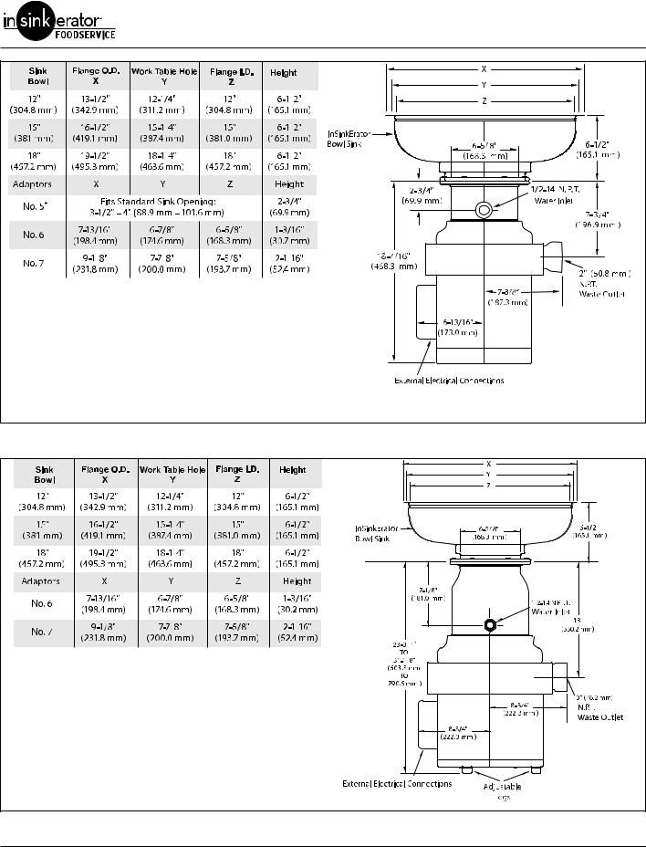
Dimensions
IMPORTANT: Use the following dimension charts for adaptor height in place of InSinkErator sink bowl height when mounting directly to a sink. Dimensions — Models SS-50, SS-75, SS-100 & SS-125.
NOTE:
 Adaptors are available upon request for all competitor sink bowls or cones.
 Please have sink/bowl cone type with the necessary dimensions when ordering adaptors.
* It is recommended to add legs (Part No.11757C) with No. 5 Mounting Assembly.
Figure 2. Dimensions — Models SS-50, SS-75, SS-100 & SS-125
Commercial Disposers
NOTE:
 Adaptors are available upon request for all competitor sink bowls or cones.
 Please have sink/bowl cone type with the necessary dimensions when ordering adaptors.
 Also available as a short body model. Reduces overall height of disposer by 1” (25.4 mm).
 Legs shipped in carton with unit. Assembly required prior to unit installation.
* It is recommended to add legs (Part No.11757C) with No. 5 Mounting Assembly.
Figure 3. Dimensions — Models SS-150 & SS-200
NOTE:
 Adaptors are available upon request for all competitor sink bowls or cones.
 Please have sink/bowl cone type with the necessary dimensions when ordering adaptors.
 Also available as a short body model. Reduces overall height of disposer by 3” (76.2 mm).
 Unit shipped with legs installed from factory. Adjustment required at time of unit installation.
Figure 4. Dimensions — Models SS-300, SS-500, SS-750 & SS1000

Commercial Disposers
Electrical Requirements
The electrical wiring on disposers shipped from the factory are not connected for a specific voltage. Refer to the Standard Motor Connection Wiring Diagram attached to the inside of the disposer terminal box cover for the correct voltage connections.
Standard disposer voltages are:
•115/208/230 volts for single phase electrical power
•208/230/460 volts for three phase electrical power
NOTE: All amp ratings denote amp draw during a grind load.
NOTE: The disposer motor phase and voltage must be the same as the line or power supply.
|
ELECTRIC SHOCK! The disposer must be |
||
|
DANGER |
||
|
permanently grounded. |
||
|
-26 |
115/208-230V, 60Hz, 1 Ph, 8.4/4.0/4.2 amps, UL |
|||
|
SS-50 |
-27 |
208-230/460V, 60Hz, 3 Ph, 2.0/2.1/1.1 amps, UL |
||
|
1/2 H.P. |
-28 |
115/208-230V, 60Hz, 1 Ph. 8.4/4.0/4.2 amps, CSA |
||
|
-29 |
208-230/460V, 60Hz, 3 Ph, 2.0/2.1/1.1 amps, CSA |
|||
|
-27 |
115/208-230V, 60Hz, 1 Ph, 10.0/4.3/5.0 amps, UL |
|||
|
SS-75 |
-28 |
208-230/460V, 60Hz, 3 Ph, 2.0/2.4/1.2 amps, UL |
||
|
3/4 HP |
-29 |
115/208-230V, 60Hz, 1 Ph, 10.4/4.3/5.0 amps, CSA |
||
|
-30 |
208-230/460V, 60Hz, 3 Ph, 2.0/2.4/1.2 amps, CSA |
|||
|
-28 |
115/208-230V, 60Hz, 1 Ph, 11.6/5.1/5.7 amps, UL |
|||
|
SS-100 |
-29 |
208-230/460V, 60Hz, 3 Ph, 2.2/3.0/1.5 amps, UL |
||
|
1 H.P. |
-30 |
115/208-230V, 60Hz, 3 Ph, 11.6/5.1/5.7 amps, CSA |
||
|
-31 |
208-230/460V, 60Hz, 3 Ph, 2.2/3.0/1.5 amps, CSA |
|||
|
-25 |
115/208-230V, 60Hz, 1 Ph, 10.6/4.5/5.3 amps, UL |
|||
|
SS-125 |
-26 |
208-230/460V, 60Hz, 3 Ph, 3.5/4.0/2.0 amps, UL |
||
|
1-1/4 H.P. |
-27 |
15/208-230V, 60Hz, 1 Ph, 10.6/4.5/5.3 amps, CSA |
||
|
-28 |
208-230/460V, 60Hz, 3 Ph, 3.5/4.0/2.0 amps, CSA |
|||
|
-34 |
115/208-230V, 60Hz, 1 Ph, 12.2/5.7/6.1, amps, UL |
|||
|
-36 |
208-230/460V, 60 Hz, 3 Ph, 3.2/4.6/2.3 amps, UL |
|||
|
SS-150 |
-37 |
208-230/460V, 60 Hz, 3 Ph, 3.2/4.6/2.3 amps, CSA |
||
|
1-1/2 H.P. |
-38 |
115/208-230V,, 60 Hz, 1 Ph, 12.2/5.7/6.1 amps, UL, short body |
||
|
-39 |
208-230/460V, 60 Hz, 3 Ph, 3.2/4.6/2.3 amps, UL, short body |
|||
|
-35 |
115/208-230V, 60 Hz, 1 Ph, 12.2/5.7/6.1 amps, CSA |
|||
|
-27 |
115/208-230V, 60 Hz, 1 Ph, 17.4/7.7/8.7 amps, UL |
|||
|
-29 |
208-230/460V, 60 Hz, 3 Ph, 3.3/5.0/2.5 amps UL |
|||
|
SS-200 |
-31 |
115/208-230V, 60 Hz, 1 Ph, 17.4/7.7/8.7 amps, UL, short body |
||
|
2 H.P. |
-32 |
208-230/460V, 60 Hz, 3 Ph, 3.3/5.0/2.5 amps, UL, short body |
||
|
-28 |
115/208-230, 60 Hz, 1 Ph, 17.4/7.7/8.7 amps, CSA |
|||
|
-30 |
208-240/460V 60Hz, 3 Ph, 3.3/5.0/2.5 amps, CSA |
|||
|
SS-300 |
-25 |
208-230/460V, 60 Hz, 3 Ph, 6.0/7.4/3.7 amps, UL |
||
|
-27 |
208-230/460V, 60 Hz, 3 Ph, 6.0/7.4/3.7 amps, UL, short body |
|||
|
3 H.P. |
||||
|
-26 |
208-230/460V, 60 Hz, 3 Ph, 6.0/7.4/3.7 amps, CSA |
|||
|
SS-500 |
-28 |
208-230/460V, 60 Hz, 3 Ph, 8.4/8.8/4.4 amps, UL |
||
|
-30 |
208-230/460V, 60 Hz, 3 Ph, 8.4/8.8/4.4 amps, UL, short body |
|||
|
5 H.P. |
||||
|
-29 |
208-230/460V, 60 Hz, 3 Ph, 8.4/8.8/4.4 amps, CSA |
|||
|
Service Manual |
5 |
|
Commercial Disposers |
|||||||||
|
SS-750 |
-13 |
208-230/460V, 60 Hz, 3 |
Ph, 9.7/12.4/6.2 amps, UL |
||||||
|
-15 |
208-230/460V, 60 Hz, 3 |
Ph, 9.7/12.4/6.2 amps, UL, short body |
|||||||
|
7-1/2 H.P. |
|||||||||
|
-14 |
208-230/460V, 60 |
Hz, 3 |
Ph, 9.7/12.4/6.2 amps, CSA |
||||||
|
SS-1000 |
-10 |
208-230/460V, 60 |
Hz, 3 |
Ph, 11.0/13.0/6.5 amps, UL |
|||||
|
-12 |
208-230/460V, 60 |
Hz, 3 |
Ph, 11.0/13.0/6.5 amps, UL, short body |
||||||
|
10 H.P. |
|||||||||
|
-11 |
208-230/460V, 60 |
Hz, 3 |
Ph, 11.0/13.0/6.5 amps, CSA |
||||||
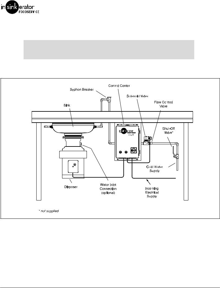
Recommended Installation
Figure 5. Recommended Installation
Commercial Disposers
PREPARATION FOR REPAIR
DANGER ELECTRIC SHOCK! Turn off water and electrical supply. Discharge capacitor with
1000 ohm jumper wire (1 Phase only). Do not use a screwdriver to discharge or capacitor may be damaged.
Removing Disposer
1.Turn off electrical supply and water supply to disposer.
2.Disconnect cold water connection from disposer body water inlet (if connected).
3.Disconnect waste line from disposer.
4.Remove terminal box retaining screw and terminal box cover. See “Terminal Box & Trim Band” on page 9. Mark motor lead wires and electrical supply wires, then disconnect wires and grounding wire from disposer.
NOTE: Make sure sink can bear weight of disposer before legs are loosened. In some cases, support disposer before loosening or removing legs.
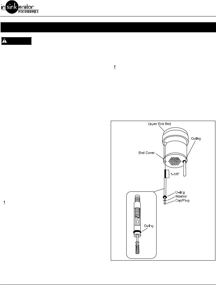
5.If equipped with legs and legs interfere with removing disposer from mounting flange, pull O-ring down disposer leg, turn each leg clockwise to raise legs and gain floor clearance.
6.Remove disposer from mounting flange by turning disposer or loosening bolts as necessary (depending on mounting flange).
7.To remove legs, remove black cap plug from bottom of support leg (Figure 6). Insert slotted screwdriver into open end of leg support tube and turn stud counterclockwise until free of upper end bell. Pull leg from disposer.
Installing Disposer
|
ELECTRIC SHOCK! Turn off water and |
||
|
DANGER |
||
|
electrical supply. Discharge capacitor |
||
|
with jumper wire (1 Phase only). |
1.If unit was equipped with legs, insert leg assemblies through end cover guide holes. Insert screwdriver into open end of leg support tube and turn stud clockwise to install. Install O-ring, washer and cap to each leg (Figure 6).
NOTE: On models SS-150 thru SS-200, legs are optional and recommended where the disposer is mounted to a thin gauge sink (16 gauge minimum), dish table, using a #5 mounting assembly or non-InSinkErator mounting adaptors. On models SS-300 and above, legs are factory installed and recessed on the unit.
2.Attach disposer to the mounting assembly by positioning in mounting flange and turning disposer into flange or tightening bolts (depending on specific mounting).
3.Adjust legs so unit is supported evenly. Push O-ring up flush with bottom of unit.
4.Connect electrical supply wires to the motor leads. Reference the wiring diagram attached to the inside of the terminal box or the Wiring Diagrams section of the Disposer Control Center Installation manual.
5.Reinstall terminal box.
|
ELECTRIC SHOCK! Make sure electrical |
||
|
DANGER |
||
|
wires are not pinched or damaged when |
||
|
installing terminal box cover. |
6.Connect waste line to disposer.
7.Connect cold water supply to disposer body water inlet (if previously installed).
8.Turn on electrical and water supply.
9.Test the disposer to ensure the cutting elements revolve and the water flows automatically. Make sure the disposer is securely mounted and does not leak from any of the connections.
Figure 6. Disposer Leg
![]()
Commercial Disposers
Common Repair Areas
GRIND CHAMBER
•Stationary Shredder Gasket
•Stationary Shredder
•Rotating Shredder
UPPER END BELL (UEB)
•Seals & Bearings
ELECTRICAL
•Overload
•Capacitor
•Stator
•Rotor & Centrifugal Switch
•Lower End Frame (LEF)
Figure 7. Common Repair Areas

Commercial Disposers
Terminal Box & Trim Band
DANGER ELECTRIC SHOCK! Turn off water and electrical supply. Discharge capacitor with
1000 ohm jumper wire (1 Phase only). Do not use a screwdriver to discharge or capacitor may be damaged.
NOTE: Terminal box and trim band are removed for all repairs except overload and start capacitor.
Removal
1.Remove screw and terminal box (Figure 8).
2.Remove two screws securing trim band (Figure 9).
3.Spread the trim seam. While pivoting trim band upward and forward, slip band over terminal box bracket and remove band from disposer.
Installation
|
ELECTRIC SHOCK! Make sure electrical |
||
|
DANGER |
||
|
wires are not pinched or damaged when |
||
|
installing terminal box cover |
1.Insert trim band onto unit. Secure with two screws and tighten.
2.Install terminal box with overload protector positioned through rubber grommet. Take care not to pinch lead wires in terminal box.
3.Secure with screw.
Figure 8. Terminal Box
Figure 9. Trim Band

Commercial Disposers
GRINDING CHAMBER
Replacing Water Inlet
NOTE: It is not necessary to remove the disposer to repair water inlet.
Water Inlet Kit part number is 13956.
1.Using a wrench, remove water inlet from upper body (Figure 10).
2.Remove any burrs on water inlet hole.
3.Wrap Teflon tape around new water inlet fitting and insert fitting through water inlet hole from inside of upper body.
4.Place O-ring in groove in water inlet nut. A small amount of grease may be used to hold O-ring in place during installation.
5.From outside of body, attach water inlet nut to water inlet fitting. Tighten nut with wrench.
NOTE: Water inlet fitting and nut are joined with a left-hand thread.
Replacing Shredder Gasket
1.Remove disposer. See “Removing Disposer” on page 7.
2.Remove screws securing tailpipe and gasket from upper end bell assembly (Figure 10).
3.Remove terminal box and trim band (Figure 10).
4.Remove screws securing body and cover assembly to upper end bell assembly (Figure 10).
5.Lift cover and upper body assembly off upper end bell assembly
6.Separate the upper body assembly from the cover.
7.Remove old gasket. Install new gasket to bottom edge of upper body (Figure 11).
8.Place cover over upper body.
9.Place cover and upper body assembly onto upper end bell assembly. There are two tabs on the inside of the cover. These tabs fit into the two side grooves on the upper end bell with the waste outlet aligned with the waste outlet cutout.
10.Secure in place with screws.
11.Install trim band and terminal box. See “Terminal Box & Trim Band” on page 9.
12.Re-install tailpipe gasket and tailpipe using screws (Figure 10).
13.Install disposer. See “Installing Disposer” on page 7.
Figure 10. Cover and Upper Body Assembly
Figure 11. Replacing Shredder Gasket

Commercial Disposers
Replacing Stationary Shredder
Removal
1.Remove disposer. See “Removing Disposer” on page 7.
2.Remove cover and upper body assembly. Perform steps 2 – 5 under “Replacing Shredder Gasket” on page 10.
3.Lubricate the full outside diameter of the shredder ring with penetrating oil.
4.Place a 1”D x 1-1/4”L long piece of pipe or similar sized hex socket over rotating shredder nut (Figure 12).
5.Using a 5/16” thick flat bar, rest bar on top of pipe or socket with flat end under shredder teeth. Strike jam release bar with a soft non-metallic mallet (rawhide, nylon, leather, wood) to break the seal and remove stationary shredder.
Do not strike stationary shredder or  shredder could be damaged.
Installation
1.Clean old silicone and dirt from upper end bell.
2.Apply water resistant silicone sealant around bottom of stationary shredder.
3.Place stationary shredder on upper end bell, aligning one stationary shredder groove with upper end bell weep hole (Figure 13). Strike stationary shredder firmly on alternate sides with soft mallet until securely seated.
Do not use metal hammer or die cast  stationary shredder will break.
4.Turn rotating shredder by hand and make sure it rotates freely.
5.Install cover and upper body. Perform steps 8–13 under “Replacing Shredder Gasket” on page 10.
Figure 12. Removing Stationary Shredder
Stationary Shredder Groove
Weep Hole
Figure 13. Aligning Stationary Shredder