-
Contents
-
Table of Contents
-
Troubleshooting
-
Bookmarks
Quick Links
®
EDGE
Pro Ti
Shape Cutting Control
Instruction Manual
807660 – Revision 3
Related Manuals for Hypertherm EDGE Pro Ti
Summary of Contents for Hypertherm EDGE Pro Ti
-
Page 1
® EDGE Pro Ti Shape Cutting Control Instruction Manual 807660 – Revision 3… -
Page 2
____________________________________________________________________________ ____________________________________________________________________________ Maintenance notes: ____________________________________________________________________________ ____________________________________________________________________________ ____________________________________________________________________________ ____________________________________________________________________________ ____________________________________________________________________________ ____________________________________________________________________________ ArcGlide, EDGE, HPR, HSD, Hypernet, Hypertherm, Phoenix, Powermax, and Sensor are trademarks of Hypertherm, Inc. and may be registered in the United States and other countries. © 2018 Hypertherm, Inc. -
Page 3
EDGE Pro Ti CNC Instruction Manual 807660 – Revision 3 English September 2018 Hypertherm, Inc. Hanover, NH 03755 USA… -
Page 4
México, D.F. C.P. 01780 (Technical Service Email) 52 55 5681 8109 Tel 52 55 5683 2127 Fax South America & Central America: Hypertherm Brasil Ltda. Soporte.Tecnico@hypertherm.com (Technical Service Email) Rua Bras Cubas, 231 – Jardim Maia Guarulhos, SP – Brasil… -
Page 5: Table Of Contents
Laser radiation ………………………………xvii Additional safety information …………………………..xvii Product Stewardship ……………………..xix Introduction ………………………………..xix National and local safety regulations ……………………….. xix Certification test marks …………………………….xix Differences in national standards …………………………xix EDGE Pro Ti CNC Instruction Manual 807660…
-
Page 6
Transfer of rights ………………………………xxvi Waterjet product warranty coverage ……………………….xxvi Product ………………………………… xxvi Parts coverage …………………………….xxvi Specifications ……………………….27 Main features of an automated cutting system ……………………..27 CNC ………………………………..29 Cutting table ………………………………29 EDGE Pro Ti CNC Instruction Manual 807660… -
Page 7
Torch height control (THC) …………………………29 Operator console …………………………….30 Oxyfuel torch ………………………………30 Marker ………………………………..30 Overview ………………………………..30 Features of the EDGE Pro Ti CNC …………………………. 31 Touchscreen ………………………………31 Operator console …………………………….31 Rear panel ………………………………32 System specifications …………………………….33 EDGE Pro Ti axis and I/O configuration ………………………. -
Page 8
Operation …………………………91 Operating the CNC ……………………………..91 Touch screen LCD …………………………….91 Screen navigation …………………………….91 Help …………………………………92 View additional manuals …………………………..93 Show bookmarks …………………………….94 Automated operations …………………………….94 Align Wizard ………………………………94 CutPro Wizard ……………………………….95 viii EDGE Pro Ti CNC Instruction Manual 807660… -
Page 9
The CNC is not recognizing a device in a USB port ………………..113 Cut quality or plasma performance issues …………………….113 The CNC feels excessively warm ……………………..113 Loading files …………………………….114 Wireless troubleshooting ………………………….114 Component locations and information ……………………….115 Operator control panel board (141058) ……………………….116 EDGE Pro Ti CNC Instruction Manual 807660… -
Page 10
Surge board (141287) …………………………….. 140 Plasma interface assembly (228256) ……………………….141 EDGE Pro Ti Parts List ……………………143 EDGE Pro Ti CNC parts …………………………..143 Sensor Ti THC parts …………………………….143 Interface assembly kits …………………………….. 143 Safety circuit kits ………………………………. 144 Diagnostic kits ……………………………… -
Page 11: Safety
Safety DANGER WARNING CAUTION RECOGNIZE SAFETY American National Standards Institute (ANSI) guidelines are used for INFORMATION safety signal words and symbols. The signal word DANGER or WARNING is used with a safety symbol. DANGER identifies the most The symbols shown in this section are used to identify potential serious hazards.
-
Page 12: Grounding Safety
Safety GROUNDING SAFETY Work lead Attach the work lead securely to the workpiece or the Input power cutting table with good metal-to-metal contact. Do not connect it to • Make sure to connect the power cord ground wire to the ground in the piece that will fall away when the cut is complete.
-
Page 13: Cutting Can Cause Fire Or Explosion
MACHINE MOTION CAN CAUSE INJURY When an original equipment manufacturer (OEM) makes a cutting system by combining Hypertherm equipment with other equipment, the end-use customer and the OEM are responsible for providing protection against the hazardous moving parts of this cutting system. However, we advise the following to prevent operator injury and equipment damage: •…
-
Page 14: Compressed Gas Equipment Safety
Safety COMPRESSED GAS EQUIPMENT GAS CYLINDERS CAN SAFETY EXPLODE IF DAMAGED • Never lubricate cylinder valves or regulators with oil or grease. Gas cylinders contain gas under high pressure. If damaged, a cylinder can explode. • Use only correct gas cylinders, regulators, hoses, and fittings designed for the specific application.
-
Page 15: A Plasma Arc Can Cause Injury And Burns
Safety A PLASMA ARC CAN CAUSE INJURY AND BURNS Instant-on torches The plasma arc will cut quickly through gloves and skin. • Keep away from the torch tip. A plasma arc ignites immediately when the torch switch is activated. • Do not hold metal near the cutting path. •…
-
Page 16: Noise Can Damage Hearing
Safety NOISE CAN DAMAGE HEARING Cutting with a plasma arc can exceed acceptable noise levels as Use ear protectors if the noise is disruptive or if there is a risk of defined by local regulations in many applications. Prolonged exposure hearing damage after all other engineering and administrative to excessive noise can damage hearing.
-
Page 17: Laser Radiation
Safety LASER RADIATION Exposure to the laser beam from a laser pointer can result in serious eye injury. Avoid direct eye exposure. On products that use a laser pointer for alignment, one of the following laser radiation labels has been applied on the product near where the laser beam exits the enclosure.
-
Page 18
Safety xviii Safety and compliance… -
Page 19: Product Stewardship
Countries that require CE marking or have compulsory EMC regulations Certified products are identified by one or more certification test marks must use CE versions of Hypertherm products with the CE marking on from accredited testing laboratories. The certification test marks are the data plate.
-
Page 20: Qualification Of Test Personnel
When a system integrator adds additional equipment; such as cutting tests prescribed by IEC 60974-4. The repair report shall indicate the tables, motor drives, motion controllers or robots; to a Hypertherm results of all tests unless an indication is made that a particular test has plasma cutting system, the combined system may be considered a not been performed.
-
Page 21: Environmental Stewardship
Any materials available on our website at www.hypertherm.com/recycle. that are cut by the end user are not provided by Hypertherm with the product. The end user is responsible for the materials being cut as well The WEEE Directive as for safety and air quality in the workplace.
-
Page 22: Proper Handling And Safe Use Of Chemicals
Material Safety Data Sheets (MSDS) or Safety Data Sheets (SDS) be made available for all chemicals. The list of chemicals is provided by Hypertherm. The MSDS are for chemicals provided with the product and other chemicals used in or on the product. MSDS can be downloaded from the Documents Library on the Hypertherm web site at www.hypertherm.com/docs.
-
Page 23: Electromagnetic Compatibility (Emc)
Introduction Methods of reducing emissions Mains supply Hypertherm’s CE-marked equipment is built in compliance with standard EN60974-10. The equipment should be installed and used in Cutting equipment must be connected to the mains supply according to accordance with the information below to achieve electromagnetic the manufacturer’s recommendations.
-
Page 24: Screening And Shielding
Electromagnetic Compatibility (EMC) Earthing of the workpiece Where the workpiece is not bonded to earth for electrical safety, nor connected to earth because of its size and position, for example, ship’s hull or building steel work, a connection bonding the workpiece to earth may reduce emissions in some, but not all instances.
-
Page 25: Warranty
Hypertherm not in strict conformity herein and as follows: if Hypertherm is notified of a defect (i) with respect with Hypertherm’s specifications and in cases of designs, processes,…
-
Page 26: Liability Cap
At all times you will have and maintain insurance in such quantities and types, and with coverage sufficient and appropriate to defend and to hold Hypertherm harmless in the event of any cause of action arising from the use of the products.
-
Page 27: Specifications
The following sections describe these components and their relationships more fully. Figure 1 Components of an automated cutting system Operator console EDGE Pro Cutting table Control box Drive amplifier Plasma system Oxyfuel cutting system Products available from Hypertherm EDGE Pro Ti CNC Instruction Manual 807660…
-
Page 28
Products available from Hypertherm Oxyfuel cutting system Figure 3 illustrates a typical cutting table with an EDGE Pro Ti CNC and other components that are described in the following sections. Figure 3 Illustration of a cutting table Plasma system Cutting table… -
Page 29: Cnc
THC, gears, rails, servo motors, and how well they are integrated (tuned) by the table manufacturer. The table manufacturer must select and install the motors that will be used with the EDGE Pro Ti CNC. For more information on the drive system for your cutting system, refer to the manual supplied by the table manufacturer.
-
Page 30: Operator Console
® A marker can be any device or process that marks a plate rather than piercing or cutting it. If the Hypertherm ArcWriter is configured in your system, refer to the ArcWriter manual (802520) for information about installation and operation. Any HPR plasma system can also be used for marking.
-
Page 31: Features Of The Edge Pro Ti Cnc
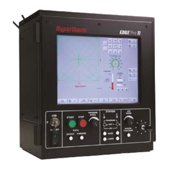
Specifications Features of the EDGE Pro Ti CNC Features of the EDGE Pro Ti CNC Touchscreen The touchscreen is a 15-inch LCD monitor combined with software that allows direct user input from the screen. A user makes selections on the screen using check boxes, radio buttons, drop-down menus, and data input. Data input boxes automatically display a numeric or alphanumeric keypad for entries in the fields.
-
Page 32: Rear Panel
Features of the EDGE Pro Ti CNC Rear panel The rear panel of the EDGE Pro Ti CNC has cable connectors for power, motion control, I/O, and communication ports. These connectors are clearly labeled with their function. Figure 6 Rear panel of the EDGE Pro Ti CNC…
-
Page 33: System Specifications
Specifications System specifications System specifications The following table contains technical specifications for the EDGE Pro Ti CNC. Table 1 System specifications for the EDGE Pro Ti CNC System features Processor ® Intel Processor Operating system Windows XPe ≥1GB Ethernet port…
-
Page 34
Operational up to 2000 m (6561 ft) Environment Pollution degree Level II Mechanical Height 490.9 mm (19.33 in.) Width 435 mm (17.13 in.) Depth 377.2 mm (14.85 in.) Weight 28.83 kg (63.55 lb) EDGE Pro Ti CNC Instruction Manual 807660… -
Page 35: Edge Pro Ti Axis And I/O Configuration
EDGE Pro Ti axis and I/O configuration The EDGE Pro Ti interface offers 2 to 4 axes of motion control using internal motor drives with 12 inputs and 12 outputs. This interface can be used to retrofit an existing system with the Edge Pro Ti interface.
-
Page 36: Specifications For The Sensor Ti Lifter
Sensor Ti lifter, motor, encoder, 4.53 k (10 lb) magnetic breakaway 128277 35 mm (1-3/8 in.) torch mounting block 128278 44 mm (1-3/4 in.) torch mounting block 128279 50 mm (2 in.) torch mounting block EDGE Pro Ti CNC Instruction Manual 807660…
-
Page 37: Installation
Claims for damage during shipment – If your unit was damaged during shipment, you must file a claim with the carrier. Hypertherm will furnish you with a copy of the bill of lading upon request. If you need additional assistance, call Customer Service listed in the front of this manual, or your authorized Hypertherm distributor.
-
Page 38: Placement Of System Components
Table manufacturers are responsible for the optimal sizing and performance characteristics of the complete machine. The EDGE Pro Ti can be used in many different configurations but the final performance characteristics of the machine depend on the total solution provided by the table manufacturer.
-
Page 39: Mounting The Cnc
Mounting the CNC Mounting the CNC Before you connect the EDGE Pro Ti CNC to other system components, mount all the components using the appropriate instructions. Do not allow the system components to lie unsecured on top of cabinets or on the floor.
-
Page 40: Mounting Hole Patterns On The Bottom Of The Cnc
Mounting hole patterns on the bottom of the CNC The EDGE Pro Ti CNC has 10 mounting holes on the bottom of the enclosure for mounting the CNC to the cutting table. Fasten the mounting screws through the holes that will provide the most stability for your CNC during the operation of your table.
-
Page 41: Mounting The Thc
Mounting the THC Mounting the THC Sensor™ Ti THC The EDGE Pro Ti CNC supports one Sensor Ti THC. Mount the Sensor Ti lifter assembly ( ) on the cutting table to 228119 take maximum advantage of the vertical travel range. Typically the bottom of the lifter should be between 15.24 and 20.32 cm (6 and 8 in.) above the cutting table.
-
Page 42: Arcglide Thc
Installation Mounting the THC ArcGlide THC The EDGE Pro Ti CNC supports a maximum of 4 ArcGlide THCs. Refer to the ArcGlide THC Instruction Manual (806450) for complete information about installing this THC. EDGE Pro Ti CNC Instruction Manual 807660…
-
Page 43
Note: The grounding practices in this section have been used on many installations with excellent results, and Hypertherm recommends that these practices be a routine part of the installation process. The actual methods used to implement these practices may vary from system to system, but should remain as consistent as possible. -
Page 44
10. Each Hypertherm component, as well as any other CNC or motor drive cabinet or enclosure, must have a separate ground cable to the common (star) ground on the table. This includes the ignition/gas connect console, whether it is bolted to the plasma system or to the cutting table. -
Page 45
14. If you are installing a voltage divider board, mount it as closely as possible to where the arc voltage is sampled. One recommended location is inside the plasma system enclosure. If a Hypertherm voltage divider board is used, the output signal is isolated from all other circuits. The processed signal should be run in twisted shielded cable (Belden 1800F or equivalent). -
Page 46
A single heavy cable then connects the gantry ground bus to the table ground bus. 1 Cable to the cutting table ground bus 2 Ground cables from components on the gantry EDGE Pro Ti CNC Instruction Manual 807660… -
Page 47
Note: This example is based on practices in North America. Other regions can have different local or national electrical codes. Hypertherm recommends that you consult your local and national electrical codes to make sure that the grounding and shielding practices that you use satisfy the requirements for your location. -
Page 48
Installation Mounting the THC EDGE Pro Ti CNC Instruction Manual 807660… -
Page 49: Configuration Diagrams
Installation Configuration diagrams Configuration diagrams Figure 12 Example of a configuration with an EDGE PRO Ti CNC and an integrated Sensor Ti lifter Lifter interface cable Motor cable Encoder cable Plasma interface cable for connection to plasma interface assembly 228256…
-
Page 50
Installation Configuration diagrams Figure 12 EDGE Pro Ti with an ArcGlide lifter Motor cable Encoder cable Motor (031143) Motor cable Encoder cable Motor (031143) Motor cable Encoder cable EDGE Pro Ti CNC Motor (031143) E-stop cable Hypernet cable to the Arc Glide THC. For complete installation information, see the ArcGlide THC Instruction Manual. -
Page 51: And Y Axis Configuration
EDGE Pro Ti CNC CNC control panel The operator console The EDGE Pro Ti comes with a 2-station operator console that allows you to operate two cutting torches or stations. The operator console allows you to: • Start and stop the cutting program.
-
Page 52: Front Panel I/O
Analog Input 2 Divided and filtered arc voltage Analog Input 3 Scaled interior temperature Analog Input 4 Note: Loading a setup file from a different Hypertherm CNC will not affect these I/O assignments. EDGE Pro Ti CNC Instruction Manual 807660…
-
Page 53: Ac Power
Power cable An AC power cable is standard equipment for North America, and is shipped with the EDGE Pro Ti CNC. For other regions, use a power cord that has an IEC–60320–C13 end which meets the requirements of local code and power connections.
-
Page 54: Chassis Grounding
Figure 16. WARNING! ELECTRIC SHOCK CAN KILL This ground connection must be wired for safe and reliable operation. Figure 16 Ground cable on the CNC To the star ground on the cutting table EDGE Pro Ti CNC Instruction Manual 807660…
-
Page 55: Interface Ports
Ethernet Cat-5e cables. This configuration must include an industrial-grade Ethernet switch to route communication from the EDGE Pro Ti to the other units in the system. Note that the EDGE Pro Ti does not support both an ArcGlide and a Sensor Ti lifter in the same system. See EDGE Pro Ti Parts List for Hypernet cable lengths and part numbers.
-
Page 56: System Connections
To minimize electromagnetic and radio frequency interference (EMI/RFI), connect all interface cable shields to the chassis using the following methods, as appropriate: • The ground screw on the EDGE Pro Ti enclosure • The dedicated ground pin on each plastic cable connector (CPC) •…
-
Page 57: Emergency Stop (E-Stop) Connection
The E-stop interface must be satisfied to engage the motors. If the E-stop is not satisfied, the motors will not spin. Figure 20 on page 58 shows a possible design for an E-stop circuit, including the circuitry that exists within the EDGE Pro Ti CNC and circuitry using an Allen Bradley safety relay.
-
Page 58: Sample E-Stop Circuit
The E-stop in Figure 20 uses Hypertherm components; an E-stop switch (428025), safety relay (003239), and reset switch (428026) and uses the EDGE Pro Ti E-stop cable to connect to the safety circuit within the CNC. Other components require a different design.
-
Page 59: Edge Pro Ti Safety Circuit
Figure 21 illustrates this circuit. Figure 20, illustrates an example of an E-stop design that might connect to the safety circuit within the EDGE Pro Ti CNC through the E-stop connector on the rear panel of the CNC.
-
Page 60: E-Stop Test Circuit
This E-stop test circuit connects to the E-stop circuit within the EDGE Pro Ti. The CPC for this test circuit connects to the E-stop connector on the rear enclosure of the CNC. AC fused disconnect Disconnect EDGE Pro Ti CNC Instruction Manual 807660…
-
Page 61
Installation Emergency stop (E-stop) connection Figure 23 EDGE Pro Ti safety circuit Power distribution board (page 121) Relay LS1 with Relay LS2 with 250 V, 10 A force-guided force-guided slow blow fuse contacts contacts Servo board (page 137) Power current control… -
Page 62: E-Stop Cable
3.05 m (10 ft) 223366 6.08 m (20 ft) 223367 7.62 m (25 ft) 223368 10.66 m (35 ft) 223369 15.25 m (50 ft) To create a custom cable, order the connector kit (428046). EDGE Pro Ti CNC Instruction Manual 807660…
-
Page 63: Motor Connection
Install the motor cables between the Axis 4 motor connector and the motor connector on the Sensor Ti and between the Axis 3, Axis 2, and Axis 1 motor connectors on the rear of the EDGE Pro Ti and the motor connector on the remaining axis motors (031143).
-
Page 64: Axis Configuration
Axis configuration The EDGE Pro Ti supports DC brush and brushless motors. Use the DIP switch on the Ti servo board (141281) to select the type of motor for each axis. Verify that the axis number and type on the rear of the enclosure matches the number of the axis on the DIP switch.
-
Page 65: Motor (031143)
2.90 kg (6.39 lb) Table 10 Motor power Pin no. Description Brushless motor A or Brush+ Brushless motor B or Brush- Brushless motor C Brake+ (24 VDC, 250 mA) Brake- Cable shield Cable shield EDGE Pro Ti CNC Instruction Manual 807660…
-
Page 66: Regeneration Circuit
Motor cable to axis 4 Motor cable to axes 1, 2, and 3 Figure 29 Motor cable Diameter = 11.6mm (0.458 in.) Bend radius = 150 mm (6.0 in.) Connect to motor connector ground stud EDGE Pro Ti CNC Instruction Manual 807660…
-
Page 67
7.62 m (25 ft) 123973 10.06 m (33 ft) 223348 10.66 m (35 ft) 123974 10.97 m (36 ft) 123902 15.25 m (50 ft) To create a custom cable, order the connector kit (428045). EDGE Pro Ti CNC Instruction Manual 807660… -
Page 68: Encoder Connection
Install the encoder cables between the Axis 4 encoder connector and the encoder connector on the Sensor Ti and between the Axis 3, Axis 2, and Axis 1 motor connectors on the rear of the EDGE Pro Ti and the motor connector on the remaining axis motors (031143).
-
Page 69: Encoder Cable
Channel A Black Channel A- Green Channel B Black Channel B- Blue Index Black Index- Yellow 6 V Hall Black Hall ground Brown Hall U Orange Hall V White Hall W Drain wire Shield EDGE Pro Ti CNC Instruction Manual 807660…
-
Page 70
10.66 m (35 ft) 223341 6.08 m (20 ft) 123971 10.97 m (36 ft) 123969 7.62 m (25 ft) 123899 15.25 m (50 ft) To create a custom cable, order the connector kit (428045). EDGE Pro Ti CNC Instruction Manual 807660… -
Page 71: I/O Connection
Installation I/O connection I/O connection Install the I/O cables in the I/O connectors on the rear of the CNC. Figure 33 EDGE Pro Ti I/O interface Table 14 Pinouts for I/O interface Connector J9 Connector J10 Connector J11 Connector J12 Pin no.
-
Page 72: I/O Cable
3.05 m (10 ft) 223350 6.08 m (20 ft) 223351 10.66 m (35 ft) 223352 7.62 m (25 ft) 223353 15.25 m (50 ft) To create a custom cable, order the connector kit (228126). EDGE Pro Ti CNC Instruction Manual 807660…
-
Page 73: Configuring I/O
I/O connection Configuring I/O The EDGE Pro Ti I/O circuitry provides inputs through optoisolators and outputs through relays. Contacts for both normally open and normally closed outputs are available. Use the DIP switch on the Relay I/O board (141278) to configure I/O.
-
Page 74: Input Modes
12 V and 24 V is required to activate each input. I/O circuits Figure 36 shows the details of connecting the I/O to common circuitry. All outputs are relay contacts rated at a maximum of 1 A, 250 VAC. EDGE Pro Ti CNC Instruction Manual 807660…
-
Page 75
Installation I/O connection Figure 36 Ti I/O circuits EDGE Pro Ti CNC Instruction Manual 807660… -
Page 76: I/O Setup Screen
Installation I/O connection I/O Setup screen The I/O setup screen in Phoenix software defines inputs, outputs, and their logic state. Figure 37 I/O setup screen in Phoenix software EDGE Pro Ti CNC Instruction Manual 807660…
-
Page 77: Plasma Connection
Plasma connection The plasma interface on the rear of the CNC is a 15-pin D-sub connector for the cable that connects the EDGE Pro Ti to the plasma interface board in the plasma system. The Plasma interface is designed for use with the Sensor Ti lifter only.
-
Page 78: Plasma Connection For Powermax Plasma Systems
Plasma connection Plasma connection for Powermax plasma systems Install plasma interface cable between the plasma interface on the rear of the EDGE Pro Ti and the connector on the rear of a Powermax plasma system with a built-in voltage divider.
-
Page 79
Use the following information to order this plasma interface cable. Part Number Length 223354 3.05 m (10 ft) 223355 6.08 m (20 ft) 223048 7.62 m (25 ft) 223356 10.66 m (35 ft) 123896 15.25 m (50 ft) EDGE Pro Ti CNC Instruction Manual 807660… -
Page 80: Plasma Connection For Generic Plasma Systems
Plasma connection for generic plasma systems To connect the plasma interface on the EDGE Pro Ti CNC to any plasma system that does not have a compatible voltage divider, install the generic plasma interface cable between the plasma interface on the EDGE Pro Ti and the 15-pin D-sub connector (P1) on the plasma interface assembly (228256) in the plasma system.
-
Page 81
Part Number Length 223358 3.05 m (10 ft) 223359 6.08 m (20 ft) 223360 7.62 m (25 ft) 223361 10.66 m (35 ft) 223362 15.25 m (50 ft) 223363 22.86 m (75 ft) EDGE Pro Ti CNC Instruction Manual 807660… -
Page 82: Plasma Interface Assembly (228256)
5. Verify that the outer jacket is a min. of 2.54 cm (1 in.) inside the 228256 and tighten the strain relief(s). 6. Before operating the equipment, verify that the connections are correct and that all live parts are enclosed and that all jacket/conductor insulation is protected against damage. EDGE Pro Ti CNC Instruction Manual 807660…
-
Page 83
15-pin D-sub connector for the plasma interface cable to the CNC I/O signals between the CNC and the control board To the star ground on the work table Arc voltage signals to the electrode on the control board EDGE Pro Ti CNC Instruction Manual 807660… -
Page 84
(+) Plasma interface board Transfer — Work (+) Transfer + Electrode (-) Arc voltage (-) For more information about the board within this assembly, see “Plasma interface board (141267)” on page 128. EDGE Pro Ti CNC Instruction Manual 807660… -
Page 85: Plasma Connection To Hsd130 Plasma Systems
Figure 46 Plasma interface cable to an HSD130 plasma system Figure 47 HSD130 plasma interface cable Diameter = 7.213 mm (0.284 in.) Bend radius = 150 mm (6 in.) EDGE Pro Ti CNC Instruction Manual 807660…
-
Page 86
Part Number Length 428019 3.05 m (10 ft) 428020 6.08 m (20 ft) 228247 7.62 m (25 ft) 428021 10.66 m (35 ft) 228248 15.25 m (50 ft) 228306 22.86 m (75 ft) EDGE Pro Ti CNC Instruction Manual 807660… -
Page 87: Lifter Interface
Lifter interface The lifter interface on the rear door of the EDGE Pro Ti is a 9-pin D-sub connector for the lifter interface cable that connects the EDGE Pro Ti to the optional, integrated Sensor Ti. The lifter interface is designed for use with the Sensor Ti lifter only and provides the proper height during cutting.
-
Page 88
Field Common Lower Limit switch (shared with input 12) Blue Field Common Breakaway switch Orange Field Common Field Common Yellow Nozzle contact -12 V Green Nozzle contact sense Violet Nozzle contact common Brown EDGE Pro Ti CNC Instruction Manual 807660… -
Page 89: Lifter Interface Cable
The lifter interface cable is a 9-pin D-sub cable that connects the lifter interface on the CNC to the Sensor Ti. Figure 49 Lifter interface cable to the Sensor Ti Lifter cable Sensor Ti Figure 50 Lifter interface cable Diameter = 6.197 mm (0.244 in.) Bend radius = 150 mm (6 in.) EDGE Pro Ti CNC Instruction Manual 807660…
-
Page 90
Part Number Length 223343 3.05 m (10 ft) 223344 6.08 m (20 ft) 223345 7.62 m (25 ft) 223346 10.66 m (35 ft) 123968 10.97 m (36 ft) 123897 15.25 m (50 ft) EDGE Pro Ti CNC Instruction Manual 807660… -
Page 91: 24 Vdc Auxiliary Power Connector
LAN cable to suppress both differential and common-mode EMI. Use one of the following filters: • Hypertherm 209195 • Fair-Rite 0431164181 Figure 53 Ferrite filter installed on a Hypernet or LAN cable EDGE Pro Ti CNC Instruction Manual 807660…
-
Page 92
Installation Hypernet and LAN cable EDGE Pro Ti CNC Instruction Manual 807660… -
Page 93: Operation
Operation Operating the CNC Phoenix software runs on the Hypertherm computer numerical controls (CNCs) and supports either a touch screen or LCD display with a USB-connected keyboard and mouse for entering information and navigating the software. For more information, see the Phoenix Software Operator’s Manual.
-
Page 94: Help
Special Setups and Station Configuration screens. This manual assumes the CNC is in Advanced Mode and shows all features with an example machine configuration. Help Choose the Help soft key to display information about each screen EDGE Pro Ti CNC Instruction Manual 807660…
-
Page 95: View Additional Manuals
View additional manuals The Help screen may also display buttons for other types of information, for example: • Manuals for the Hypertherm equipment installed with your CNC, such as plasma systems or torch height controls. • Manuals for equipment provided by your table manufacturer.
-
Page 96: Show Bookmarks
To start the Align Wizard, choose Shape Library on the Main screen, then choose Shape Wizard, Shape Options, Align. The Align Wizard may launch automatically. If not, choose the Align Wizard soft key. For more information, see Align Wizard in the Arranging Parts chapter of the Phoenix Software Operator’s Manual. EDGE Pro Ti CNC Instruction Manual 807660…
-
Page 97: Cutpro Wizard
Updating the cut charts Hypertherm provides cut charts in two different file types: .fac and .usr. The .fac files are the factory-default cut charts. These cut charts cannot be changed. The .usr cut charts contain any changes you have made to a cut chart and saved with the Save Process soft key.
-
Page 98
4. If you have modified cut charts to copy back onto the hard drive, you will need to exit Phoenix and use Windows® Explorer to copy your .usr files back onto the hard drive. The cut chart folder is c:\Phoenix\CutCharts. EDGE Pro Ti CNC Instruction Manual 807660… -
Page 99: Maintenance And Diagnostics
See the Safety section in this manual for more safety precautions. Introduction Hypertherm assumes that the service personnel who perform troubleshooting testing are high-level electronic service technicians who have worked with high-voltage electro-mechanical systems. Knowledge of final isolation troubleshooting techniques is also assumed.
-
Page 100: Touchscreens, Drops Of Water, And Unintended Motion
• If water could accidently hit the touchscreen, do not include the jog keys in the watch windows. For additional information, contact your local Hypertherm Technical Service team. THC Slide Maintenance The ball screw in the lifter should be cleaned and lubricated every 6 months.
-
Page 101: Diagnostic Tests
Note: A test kit (428057) is required to perform the following diagnostic tests. Machine interface tests If you are using an EDGE Pro Ti CNC, you can perform diagnostic tests with the following connectors and Phoenix software to test the interface ports on the CNC: •…
-
Page 102: Lan And Hypernet Tests
2. Follow the instructions on the screen to plug in the tester. 3. Choose Test on the Hypernet or LAN test screen. A message informs you if the test is successful. If either test fails, contact your table manufacturer to replace the motherboard (141110). EDGE Pro Ti CNC Instruction Manual 807660…
-
Page 103: Serial Test
3. Choose Test on the serial test screen. A message informs you if the test is successful. If the test fails, contact your table manufacturer to replace the utility and serial isolation board (141307). EDGE Pro Ti CNC Instruction Manual 807660…
-
Page 104: Usb Test
3. Follow the instructions on the screen to insert the memory stick in the USB port on the front of the CNC. 4. Press Test. A message informs you if the test is successful. If the test fails on both USB ports, contact your table manufacturer to replace the motherboard (141110). EDGE Pro Ti CNC Instruction Manual 807660…
-
Page 105: E-Stop Test
Yellow band, for sourced contact mode Yellow band, for sourced contact mode Install this end in the I/O 1 – 3 connector Conduct this test to verify that the E-stop circuit is functioning correctly. EDGE Pro Ti CNC Instruction Manual 807660…
-
Page 106
4. If the test fails, conduct the I/O test (see page 107) to verify that the I/O is functioning correctly. 5. If the I/O test is successful, replace the surge and safety board (141287). 6. If the I/O test fails, replace the I/O relay board (141278) EDGE Pro Ti CNC Instruction Manual 807660… -
Page 107: I/O Test
An I/O point is malfunctioning. • You need to eliminate CNC I/O operation as a problem in the system. • A continuous fault is occurring, such as a limit switch that is not turning on or clearing. EDGE Pro Ti CNC Instruction Manual 807660…
-
Page 108
Maintenance and Diagnostics Diagnostic tests These screens test I/O contacts in dry mode. These screens test I/O contacts in sourced mode. EDGE Pro Ti CNC Instruction Manual 807660… -
Page 109
4. If the first test fails, follow the instructions on the screen to conduct the second test and isolate the I/O points that are causing the problem. 5. If the second test fails, the screen reports the number of the failed input or output. Contact your table manufacturer to replace the I/O board (141278). EDGE Pro Ti CNC Instruction Manual 807660… -
Page 110: Plasma And Lifter Tests
2. Follow the instructions on the screen to install the tester on the back of the CNC. 3. Press Test. A message informs you if the test is successful. 4. If the test fails, replace the I/O relay board (141278) or the utility and serial isolation board (141307). EDGE Pro Ti CNC Instruction Manual 807660…
-
Page 111: Operator Panel Test
If multiple components fail, contact your table manufacturer to replace one or all of the following parts: • Ribbon cable to the operator control panel board (223013) • Operator control panel board (141058) • Utility and serial isolation board (141307) EDGE Pro Ti CNC Instruction Manual 807660…
-
Page 112: Troubleshooting
Troubleshooting Troubleshooting Introduction Hypertherm assumes that the service personnel performing the troubleshooting are high-level electronic service technicians who have worked with high-voltage electro-mechanical systems. Knowledge of final isolation troubleshooting techniques is also assumed. In addition to being technically qualified, maintenance personnel must perform all tests with safety in mind. Refer to the Safety section for operating precautions and warning formats.
-
Page 113: Common Situations
2. Move or press any of the components on the physical front panel to verify the proper operation on the CNC screen. If any of these tests fail, replace the individual component on the front panel (see EDGE Pro Ti Parts List for the appropriate part number).
-
Page 114: Input Failure
1. The acceleration rate may be too high. Experiment with this setting to change the need for braking. 2. The gear ratio may be inadequate. 3. Axis motors are inadequate. 4. Hardware somewhere is defective. EDGE Pro Ti CNC Instruction Manual 807660…
-
Page 115: Motion Issues
3. If the external fan is running and the CNC is still excessively warm, open the front door of the CNC and verify that the internal fan is running. If the fan is not running, replace the internal fan (228474). EDGE Pro Ti CNC Instruction Manual 807660…
-
Page 116: Loading Files
For best network performance, minimize the number of clients on the wireless network. • Avoid connecting slower wireless devices to the network (for example, 802.11B devices) as the entire network may degrade to that level of performance. EDGE Pro Ti CNC Instruction Manual 807660…
-
Page 117: Component Locations And Information
Component locations and information Component locations and information The following pages provide details about the major components of the EDGE Pro Ti. Refer toEDGE Pro Ti Parts List for the corresponding replacement kits and part numbers. Note: Use the instructions in Replacement Parts for EDGE Pro CNC Field Service Bulletin (806440) to replace parts in the EDGE Pro CNC.
-
Page 118: Operator Control Panel Board (141058)
Maintenance and Diagnostics Operator control panel board (141058) Operator control panel board (141058) Figure 63 Operator control panel board EDGE Pro Ti CNC Instruction Manual 807660…
-
Page 119
MB On/Off 1 Down Station enable LED1 MB On/Off 2 Left Station enable LED2 Logic ground Right Motherboard On/Off 1 Logic ground Motherboard On/Off 2 Logic ground Cut speed Jog sped 4.096 V Reference EDGE Pro Ti CNC Instruction Manual 807660… -
Page 120: Motherboard (141110)
POST display PCI 5 (ready state is 00) PCI stack Motherboard ON/OFF signals PCI slot 2 PCI slot 3 PCI slot 4 PCI slot 5 EDGE Pro Ti PCI boards Wireless None Utility/serial isolation EDGE Pro Ti CNC Instruction Manual 807660…
-
Page 121: Power Distribution Board (141153)
12 V Field DC Green -12 V Field DC Green 24 V Field DC Green 5 V ATX DC Green 12 V ATX DC Green -12 V ATX DC Green External fan Green AC power Green EDGE Pro Ti CNC Instruction Manual 807660…
-
Page 122
Logic +12 V +5 V Logic ground -12 V Logic ground +12 V Logic +5 V Field ground J5 Field DC out Field ground +24 V +5 V -12 V +12 V Field ground EDGE Pro Ti CNC Instruction Manual 807660… -
Page 123: 4-Axis Mcc Board (141191)
I/O 1 to 12 Axis 1 – 4 Signal Watch dog LED Axis 4 enabled ON = enabled Axis 3 enabled Axis 2 enabled Axis 1 enabled Installed in PCI slot 5 on the motherboard EDGE Pro Ti CNC Instruction Manual 807660…
-
Page 124
Ground Axis 1A Analog common Axis 1B Axis 1 analog Axis 1Z Axis 2 analog Axis 2A Axis 3 analog Axis 2B Axis 4 analog Axis 2Z Not connected Axis 3A Not connected EDGE Pro Ti CNC Instruction Manual 807660… -
Page 125
Maintenance and Diagnostics 4-axis MCC board (141191) Axis 3B Ground Axis 3Z +5 V Axis 4A +5 V Axis 4B +12 V Axis 4Z -12 V Not connected Ground EDGE Pro Ti CNC Instruction Manual 807660… -
Page 126: Utility And Serial Isolation Board (141307)
COM 4 2×5 Jumpers = 2 connectors RS-422 J5 Port A Serial 1 J6 To motherboard and power distribution RS-232 Installed in PCI slot 4 on the J8 Port B Serial 2 motherboard EDGE Pro Ti CNC Instruction Manual 807660…
-
Page 127
Station enable LED 2 Signal ground 2 Motherboard ON/OFF 1 Not connected Motherboard ON/OFF 2 Receive B+ Cut speed Not connected Jog speed Not connected 4.096 V Ground 12 V Arc voltage Not connected EDGE Pro Ti CNC Instruction Manual 807660… -
Page 128: Plasma Interface Board (141267)
J1 and J3 carry I/O signals between the 15-pin D-sub connector (P1) for the plasma interface cable to the CNC voltage signals (-) from the control board in CNC and the control board in the the plasma system plasma system EDGE Pro Ti CNC Instruction Manual 807660…
-
Page 129
Start output- (contact closure) +12 V output (maximum 50 mA) Hold output+ Hold output- J2 Negative electrode Arc voltage- Arc voltage- J3 I/O terminal block Transfer input+ Transfer input- Ground Not used Not used EDGE Pro Ti CNC Instruction Manual 807660… -
Page 130
(default) (default) Refer to page 73 for more information about shared inputs and input modes. AV Utility I/O 4 – 6 Clean and field power I/O 1 – 3 To surge board EDGE Pro Ti CNC Instruction Manual 807660… -
Page 131
Green when Input 13, Transfer (also Machine Motion), is activated by the plasma system Green when Output 14, Hold Ignition, is activated by Phoenix Green when Output 13, Plasma Start (also Cut Control), is activated by Phoenix EDGE Pro Ti CNC Instruction Manual 807660… -
Page 132
Green when Input 16, Torch Collision, is in run condition (the torch is in place). This LED turns off during a torch collision. Green when Input 15, Nozzle Sense 1 (also Ohmic Contact or Plate Contact) is activated, when the torch makes contact with the work piece. EDGE Pro Ti CNC Instruction Manual 807660… -
Page 133
Plasma start output Plasma start output Hold ignition output + Hold ignition output Transfer input+ Transfer input- Field ground Field ground Field ground Field ground Field ground Electrode arc voltage- Electrode arc voltage+ Not connected EDGE Pro Ti CNC Instruction Manual 807660… -
Page 134
Axis 4 fault Input 8 Not connected Output 8 E-stop active Input 9 Not connected Output 9 AC/DC power good Input 10 Not connected Output 10 Logic ground Input 11, Upper limit Not connected EDGE Pro Ti CNC Instruction Manual 807660… -
Page 135
Maintenance and Diagnostics Relay I/O board (141278) Pin no. Signal Pin no. Signal Output 11 Not connected Input 12, Lower limit Not connected Output 12 Not connected Input 13 Logic ground EDGE Pro Ti CNC Instruction Manual 807660… -
Page 136
Input 8 common Input 11 common Input 3 Input 6 Input 9 Input 12 (shared with lifter Upper Limit) Input 3 common Input 6 common Input 9 common Input 12 common Shield Shield Shield Shield EDGE Pro Ti CNC Instruction Manual 807660… -
Page 137: 4-Axis Dc Servo Board (141281)
J5 To MCC board connector Axis 1 motor J4 Clean 5 and 12 connector VDC in J7 Field 24 V out J8 12 V field voltage for Axis 1 encoder external fan connector EDGE Pro Ti CNC Instruction Manual 807660…
-
Page 138
Not connected Axis 3A Not connected Axis 3B Logic ground Axis 3Z Logic +5 V Axis 4A Logic +5 V Axis 4B Logic +12 V Axis 4Z Logic -12 V Not connected Logic ground EDGE Pro Ti CNC Instruction Manual 807660… -
Page 139
Axis 4 fault Logic ground Table 42 Pinouts for J7 and J8 Pin no. Signal J7 Field 24 V output +24 V Field ground Not connected J8 Exterior fan Field ground +12 V Field ground EDGE Pro Ti CNC Instruction Manual 807660… -
Page 140
Field ground Field ground Field ground Encoder/Hall A Encoder/Hall A Encoder/Hall A Encoder/Hall A Encoder/Hall B Encoder/Hall B Encoder/Hall B Encoder/Hall B Encoder/Hall C Encoder/Hall C Encoder/Hall C Encoder/Hall C Shield Shield Shield Shield EDGE Pro Ti CNC Instruction Manual 807660… -
Page 141: Servo Amplifier (228360)
Maintenance and Diagnostics 4-axis DC servo board (141281) Servo amplifier (228360) Figure 71 Servo amplifier board These pins attach the amplifier to the servo board (141281) Top side of the servo amplifier board EDGE Pro Ti CNC Instruction Manual 807660…
-
Page 142
Green. Illuminated when E-stop CPC pins 8 to 9 are closed and relay LS2 has power. Line 2 60 VDC power supply Green. Illuminated when E-stop CPC pins 6 to 7 are closed and relay LS1 has power. EDGE Pro Ti CNC Instruction Manual 807660… -
Page 143
J3 Terminal block for power supply I/O Plasma Start+ Transfer+ Plasma Start- Transfer- +12 VDC Field ground Hold Ignition+ Not connected Hold Ignition- Not connected J2 Terminal block for arc voltage Arc voltage 250 V Arc voltage 250 V EDGE Pro Ti CNC Instruction Manual 807660… -
Page 144
Maintenance and Diagnostics Plasma interface assembly (228256) EDGE Pro Ti CNC Instruction Manual 807660… -
Page 145: Plasma Interface Assembly 228256
Kit number Description Plasma interface assembly 228256 Installed in plasma systems with no compatible, built-in voltage divider See Cables for HSD plasma interface and cable kits Plasma interface assembly for HSD130 plasma systems EDGE Pro Ti CNC Instruction Manual 807660…
-
Page 146: Safety Circuit Kits
Plasma interface cable for connection to plasma interface assembly 228256 223359 6.08 m (20 ft) 223360 7.62 m (25 ft) 223361 10.66 m (35 ft) 228249 15.25 m (50 ft) 223363 22.86 m (75 ft) EDGE Pro Ti CNC Instruction Manual 807660…
-
Page 147
7.62 m (25 ft) 223223 10.66 m (35 ft) 223008 15.25 m (50 ft) 223099 22.86 m (75 ft) 223100 30.48 m (100 ft) 223101 45.72 m (150 ft) 223102 60.96 m (200 ft) EDGE Pro Ti CNC Instruction Manual 807660… -
Page 148: Cable Connector Kits
Wireless board (141223), includes 2 cables and antennas 428001 Utility and serial isolation board (141307) 428004 4-axis MCC board (141191) 228454 Motherboard (141110), with CPU, heatsink/fan, and RAM 228448 Power distribution board (141153) EDGE Pro Ti CNC Instruction Manual 807660…
-
Page 149
EDGE Pro Ti Parts List PCB kits EDGE Pro Ti CNC Instruction Manual 807660… -
Page 150: Additional Kits
Joy stick 228471 Speed potentiometer 228470 Stop switch assembly, red 228468 Start switch assembly, green 228467 Power switch 228465 Station select toggle switch 228469 White pushbutton switch assembly 228463 Hypernet/LAN RJ-45 connector 228445 EDGE Pro Ti CNC Instruction Manual 807660…
-
Page 151: Wiring Diagrams
Use the sheet number to find the reference sheet. Line up the coordinates A–D on the Y axis and numbers 1–4 on the X axis of each sheet to find the reference blocks (similar to a road map). EDGE Pro Ti CNC Instruction Manual 807660…
-
Page 152: Wiring Diagram Symbols
Shield Door interlock Plug Shunt PNP transistor Spark gap Feed-through LC Potentiometer Switch, flow Push button, Switch, level, Filter, AC normally closed normally closed Push button, Switch, pressure, Fuse normally open normally closed EDGE Pro Ti CNC Instruction Manual 807660…
-
Page 153
Switch, temperature, Transformer, air core normally closed Switch, temperature, Transformer, coil normally open Terminal block Triac Time delay closed, VAC source NC/off Torch symbols Electrode Nozzle Shield Torch Torch, HyDefinition™ Section EDGE Pro Ti CNC Instruction Manual 807660… -
Page 154
Wiring Diagrams Wiring diagram symbols EDGE Pro Ti CNC Instruction Manual 807660… -
Page 155: Edge Pro Ti System Wiring
SHEET 10 SHEET 8 SHEET 9 EXTERIOR PORT PORT PORT 223310 141278 141281 127189 SHEET 2 SHEET 2 SHEET 2 SAFETY PLASMA LIFTER 24VDC INTFC INTFC (CPC) (DB15) (DB9) EDGE Pro Ti system wiring EDGE Pro Ti CNC Instruction Manual 807660…
-
Page 156: Motherboard
6-D1 HYPERNET 223010 (BLU) RJ-45 JACK TOUCHSCREEN VGA 108751 SHEET 223028 3-C4 AB EDGE PRO Ti (REAR) TOUCHSCREEN USB VIEW A-A USB CABLE SHEET EDGE PRO Ti 3-C4 (FRONT) 223244 223244 MOTHERBOARD Motherboard EDGE Pro Ti CNC Instruction Manual 807660…
-
Page 157: Power Distribution Board
3 LINE/L1 2 NEUTRAL/L2 1 EARTH GROUND ATX PWR 100-240V AC SHEET 223025 11-C4 229348 SATA POWER 4 LINE/L1 3 NEUTRAL/L2 1 EARTH GROUND 2 LINE/L1 1 NEUTRAL/L2 223304 SHEET 10-D4 Power distribution board EDGE Pro Ti CNC Instruction Manual 807660…
-
Page 158: Operator Panel Board
+12V 34 LOWER 2 LOWER 1 BACK UP PWR SWITCH 229241 SHEET SHEET 5-B2 5-C1 229252 229241 SHEET 229241 SHEET 5-A2 5-A3 SHEET 229241 229241 SHEET 5-A2 OPERATOR PANEL PCB 5-A4 Operator panel board EDGE Pro Ti CNC Instruction Manual 807660…
-
Page 159: Operator Panel Components
STATION 2 LOWER STATION 1 LOWER FORWARD ON PATH BACKWARD ON PATH MANUAL FUNCTION 229241 229241 229241 229241 229241 SHEET SHEET SHEET SHEET SHEET 4-B4 4-A3 4-B3 4-B2 4-B2 OPERATOR PANEL COMPONENTS Operator panel components EDGE Pro Ti CNC Instruction Manual 807660…
-
Page 160: Utility And Serial Board
TO POWER N/C 2 TXDB+ DISTRIBUTION PCB SHEET J8 (SERIAL 2) GROUND 3 GROUND 3-C4 MOTHERBOARD ON/OFF2 4 RS232 RXDB+ MOTHERBOARD ON/OFF1 5 229273 TO MOTHERBOARD SHEET 2-D1 UTILITY/SERIAL PCB Utility and serial board EDGE Pro Ti CNC Instruction Manual 807660…
-
Page 161: Mcc Board
MCC board J2 DRIVE/ENCODER J1 I/O 1-24 J3 I/O 25-48 (NOT USED) 223016 (I/O 1-24) BLACK SHEET 8-D1 223014 (6 AXIS DRV/ENC) SHEET 9-D3 (NOT USED) PCB5 6 AXIS MCC PCB 141191 MCC board EDGE Pro Ti CNC Instruction Manual 807660…
-
Page 162: I/O Board
INPUT 9 INPUT 12 INPUT 3 COM INPUT 6 COM INPUT 9 COM INPUT 12 COM PLATE CONTACT SENSE 8 SHIELD SHIELD SHIELD PLATE CONTACT COM 9 SHIELD N/C 10 I/O INTERFACE I/O board EDGE Pro Ti CNC Instruction Manual 807660…
-
Page 163: 6-Axis Servo Board
BRAKE + BRAKE + BRAKE (+24 VDC) N/C 3 BRAKE — BRAKE — BRAKE — BRAKE (COM) 2 BLK GROUND 2 SHIELD SHIELD SHIELD SHIELD +24V 1 SHIELD SHIELD SHIELD SHIELD 6-Axis servo board EDGE Pro Ti CNC Instruction Manual 807660…
-
Page 164: Surge Board
EDGE Pro Ti CNC CUSTOMER SUPPLIED EDGE Pro Ti CNC SEE OPTIONS POWER Power Entry Module POWER Power Entry Module VAC INPUT WIRING VAC INPUT WIRING OPTION 1 OPTION 2 SURGE PCB Surge board EDGE Pro Ti CNC Instruction Manual 807660…
-
Page 165: Atx Power Supply
YEL +12V +5VSB GROUND 18 BLU -12V +12V GROUND 19 BRN +24V +12V GRY PWR GOOD (PGD) N/C 20 +3.3V GRN PS_ON +12V 21 229404 GROUND 22 ATX POWER SUPPLY ATX power supply EDGE Pro Ti CNC Instruction Manual 807660…
-
Page 166: 60 Vdc Power Supply
GROUND 1 GROUND 2 AUX OUTPUT 12V 3 REMOTE ON/OFF 4 AUX GROUND 5 AUX GROUND 6 ALARM 7 ALARM GROUND 8 223314 SHEET 8-C2 60V DC PWR SUPPLY 60 VDC power supply EDGE Pro Ti CNC Instruction Manual 807660…
Руководство пользователя ЧПУ Hypertherm EDGE Pro (программирование).
Формат: PDF
ENTERING INTO THE LICENSE AGREEMENT SET FORTH BELOW (THE “LICENSE
AGREEMENT”) GIVES YOU THE RIGHT TO USE THE HYPERTHERM TECHNOLOGY
AND RELATED SOFTWARE AND EMBODIED THEREIN WITH HYPERTHERM HPR XD
PLASMA SYSTEMS.
PLEASE READ THE LICENSE AGREEMENT CAREFULLY BEFORE USING THE
SOFTWARE.
ВН�?МАН�?Е!
Вся информация, которая размещается на сайте носит ознакомительный характер. Мы стремимся к тому, чтобы Вы получали только достоверную, максимально полную и точную информацию. Но мы не исключаем, что некоторая информация может со временем утратить свою актуальность, допускаем возможность ошибок в содержании.
�?нформация на сайте размещается в исходном виде. Мы не даем гарантии на полноту и актуальность информации. �?нформация предоставляется также без каких-либо других явно или неявно выраженных или предполагаемых гарантий.
Администрация сайта оставляет за собой право, не уведомляя пользователей и посетителей ресурса, вносить изменения в контент.
Администрация сайта не несет ответственности за информацию, предоставленную пользователями.
На сайте есть ссылки на сторонние ресурсы (сайты), на которые мы не имеем никакого влияния. Ссылки на другие ресурсы предназначены для того, чтобы пользователю было удобнее искать информацию по схожей тематике. Мы не несем ответственности за содержание других сайтов (контент), за их доступность пользователям.
Нет и не может быть таких обстоятельств, при которых владелец (администрация) сайта будет нести какую-либо ответственность перед какой-либо стороной за прямой, непрямой или косвенно причиненный ущерб из-за использования информации, находящейся на страницах этого сайта, или информации на том сайте, на который имеется гиперссылка с этого ресурса. Ни при каких обстоятельствах мы не будем нести ответственность за возможную, но упущенную выгоду, потерю программ или данных, приостановку вашей хозяйственной деятельности и в аналогичных случаях, даже если будем явно проинформированы о большой вероятности подобного ущерба.
�?нтернет не обеспечивает надежной защиты данных и информации, поэтому не несет и не может нести ответственность за информацию, которую получают пользователи из �?нтернета.
Посещая данный сайт и используя его контент в своих целях, Вы прямо выражаете свое согласие с данным «Отказом от ответственности» и принимаете всю ответственность на себя.
Администрация сайта в любое время может и имеет право вносить изменения в эти правила. Они вступают в силу безотлагательно с этого момента. Если Вы продолжаете пользоваться сайтом после того, как в «Отказ от ответственности» внесены изменения, значит — Вы автоматически согласились на соблюдение обновленных правил.
Владельцы и создатели данного ресурса не несут ответственности за содержание ссылок, за их использование и за информацию, размещенную на данном сайте, как не несут ответственность за игнорирование пользователями коммерческого статуса того программного обеспечения, на которое ведут ссылки с этого сайта.
Авторское право и право на товарный знак
Мы стремимся соблюдать авторские права других собственников и использовать собственные или не требующие лицензирования материалы. Загрузка и копирование текстовых материалов, изображений, фотографий или иных файлов с нашего сайта допускается только для личного, некоммерческого использования. Поскольку содержимое этого раздела сайта создается из открытых общедоступных и бесплатных источников. Если вам стало известно об авторском праве на какой-либо материал на сайте, пожалуйста, сообщите нам. После уведомления о нарушениях, мы удалим такое содержимое немедленно.
-
Page 1
® EDGE Pro Ti Shape Cutting Control Instruction Manual 807660 – Revision 3… -
Page 2
____________________________________________________________________________ ____________________________________________________________________________ Maintenance notes: ____________________________________________________________________________ ____________________________________________________________________________ ____________________________________________________________________________ ____________________________________________________________________________ ____________________________________________________________________________ ____________________________________________________________________________ ArcGlide, EDGE, HPR, HSD, Hypernet, Hypertherm, Phoenix, Powermax, and Sensor are trademarks of Hypertherm, Inc. and may be registered in the United States and other countries. © 2018 Hypertherm, Inc. -
Page 3
EDGE Pro Ti CNC Instruction Manual 807660 – Revision 3 English September 2018 Hypertherm, Inc. Hanover, NH 03755 USA… -
Page 4
México, D.F. C.P. 01780 (Technical Service Email) 52 55 5681 8109 Tel 52 55 5683 2127 Fax South America & Central America: Hypertherm Brasil Ltda. Soporte.Tecnico@hypertherm.com (Technical Service Email) Rua Bras Cubas, 231 – Jardim Maia Guarulhos, SP – Brasil… -
Page 5: Table Of Contents
Laser radiation ………………………………xvii Additional safety information …………………………..xvii Product Stewardship ……………………..xix Introduction ………………………………..xix National and local safety regulations ……………………….. xix Certification test marks …………………………….xix Differences in national standards …………………………xix EDGE Pro Ti CNC Instruction Manual 807660…
-
Page 6
Transfer of rights ………………………………xxvi Waterjet product warranty coverage ……………………….xxvi Product ………………………………… xxvi Parts coverage …………………………….xxvi Specifications ……………………….27 Main features of an automated cutting system ……………………..27 CNC ………………………………..29 Cutting table ………………………………29 EDGE Pro Ti CNC Instruction Manual 807660… -
Page 7
Torch height control (THC) …………………………29 Operator console …………………………….30 Oxyfuel torch ………………………………30 Marker ………………………………..30 Overview ………………………………..30 Features of the EDGE Pro Ti CNC …………………………. 31 Touchscreen ………………………………31 Operator console …………………………….31 Rear panel ………………………………32 System specifications …………………………….33 EDGE Pro Ti axis and I/O configuration ………………………. -
Page 8
Operation …………………………91 Operating the CNC ……………………………..91 Touch screen LCD …………………………….91 Screen navigation …………………………….91 Help …………………………………92 View additional manuals …………………………..93 Show bookmarks …………………………….94 Automated operations …………………………….94 Align Wizard ………………………………94 CutPro Wizard ……………………………….95 viii EDGE Pro Ti CNC Instruction Manual 807660… -
Page 9
The CNC is not recognizing a device in a USB port ………………..113 Cut quality or plasma performance issues …………………….113 The CNC feels excessively warm ……………………..113 Loading files …………………………….114 Wireless troubleshooting ………………………….114 Component locations and information ……………………….115 Operator control panel board (141058) ……………………….116 EDGE Pro Ti CNC Instruction Manual 807660… -
Page 10
Surge board (141287) …………………………….. 140 Plasma interface assembly (228256) ……………………….141 EDGE Pro Ti Parts List ……………………143 EDGE Pro Ti CNC parts …………………………..143 Sensor Ti THC parts …………………………….143 Interface assembly kits …………………………….. 143 Safety circuit kits ………………………………. 144 Diagnostic kits ……………………………… -
Page 11: Safety
Safety DANGER WARNING CAUTION RECOGNIZE SAFETY American National Standards Institute (ANSI) guidelines are used for INFORMATION safety signal words and symbols. The signal word DANGER or WARNING is used with a safety symbol. DANGER identifies the most The symbols shown in this section are used to identify potential serious hazards.
-
Page 12: Grounding Safety
Safety GROUNDING SAFETY Work lead Attach the work lead securely to the workpiece or the Input power cutting table with good metal-to-metal contact. Do not connect it to • Make sure to connect the power cord ground wire to the ground in the piece that will fall away when the cut is complete.
-
Page 13: Cutting Can Cause Fire Or Explosion
MACHINE MOTION CAN CAUSE INJURY When an original equipment manufacturer (OEM) makes a cutting system by combining Hypertherm equipment with other equipment, the end-use customer and the OEM are responsible for providing protection against the hazardous moving parts of this cutting system. However, we advise the following to prevent operator injury and equipment damage: •…
-
Page 14: Compressed Gas Equipment Safety
Safety COMPRESSED GAS EQUIPMENT GAS CYLINDERS CAN SAFETY EXPLODE IF DAMAGED • Never lubricate cylinder valves or regulators with oil or grease. Gas cylinders contain gas under high pressure. If damaged, a cylinder can explode. • Use only correct gas cylinders, regulators, hoses, and fittings designed for the specific application.
-
Page 15: A Plasma Arc Can Cause Injury And Burns
Safety A PLASMA ARC CAN CAUSE INJURY AND BURNS Instant-on torches The plasma arc will cut quickly through gloves and skin. • Keep away from the torch tip. A plasma arc ignites immediately when the torch switch is activated. • Do not hold metal near the cutting path. •…
-
Page 16: Noise Can Damage Hearing
Safety NOISE CAN DAMAGE HEARING Cutting with a plasma arc can exceed acceptable noise levels as Use ear protectors if the noise is disruptive or if there is a risk of defined by local regulations in many applications. Prolonged exposure hearing damage after all other engineering and administrative to excessive noise can damage hearing.
-
Page 17: Laser Radiation
Safety LASER RADIATION Exposure to the laser beam from a laser pointer can result in serious eye injury. Avoid direct eye exposure. On products that use a laser pointer for alignment, one of the following laser radiation labels has been applied on the product near where the laser beam exits the enclosure.
-
Page 18
Safety xviii Safety and compliance… -
Page 19: Product Stewardship
Countries that require CE marking or have compulsory EMC regulations Certified products are identified by one or more certification test marks must use CE versions of Hypertherm products with the CE marking on from accredited testing laboratories. The certification test marks are the data plate.
-
Page 20: Qualification Of Test Personnel
When a system integrator adds additional equipment; such as cutting tests prescribed by IEC 60974-4. The repair report shall indicate the tables, motor drives, motion controllers or robots; to a Hypertherm results of all tests unless an indication is made that a particular test has plasma cutting system, the combined system may be considered a not been performed.
-
Page 21: Environmental Stewardship
Any materials available on our website at www.hypertherm.com/recycle. that are cut by the end user are not provided by Hypertherm with the product. The end user is responsible for the materials being cut as well The WEEE Directive as for safety and air quality in the workplace.
-
Page 22: Proper Handling And Safe Use Of Chemicals
Material Safety Data Sheets (MSDS) or Safety Data Sheets (SDS) be made available for all chemicals. The list of chemicals is provided by Hypertherm. The MSDS are for chemicals provided with the product and other chemicals used in or on the product. MSDS can be downloaded from the Documents Library on the Hypertherm web site at www.hypertherm.com/docs.
-
Page 23: Electromagnetic Compatibility (Emc)
Introduction Methods of reducing emissions Mains supply Hypertherm’s CE-marked equipment is built in compliance with standard EN60974-10. The equipment should be installed and used in Cutting equipment must be connected to the mains supply according to accordance with the information below to achieve electromagnetic the manufacturer’s recommendations.
-
Page 24: Screening And Shielding
Electromagnetic Compatibility (EMC) Earthing of the workpiece Where the workpiece is not bonded to earth for electrical safety, nor connected to earth because of its size and position, for example, ship’s hull or building steel work, a connection bonding the workpiece to earth may reduce emissions in some, but not all instances.
-
Page 25: Warranty
Hypertherm not in strict conformity herein and as follows: if Hypertherm is notified of a defect (i) with respect with Hypertherm’s specifications and in cases of designs, processes,…
-
Page 26: Liability Cap
At all times you will have and maintain insurance in such quantities and types, and with coverage sufficient and appropriate to defend and to hold Hypertherm harmless in the event of any cause of action arising from the use of the products.
-
Page 27: Specifications
The following sections describe these components and their relationships more fully. Figure 1 Components of an automated cutting system Operator console EDGE Pro Cutting table Control box Drive amplifier Plasma system Oxyfuel cutting system Products available from Hypertherm EDGE Pro Ti CNC Instruction Manual 807660…
-
Page 28
Products available from Hypertherm Oxyfuel cutting system Figure 3 illustrates a typical cutting table with an EDGE Pro Ti CNC and other components that are described in the following sections. Figure 3 Illustration of a cutting table Plasma system Cutting table… -
Page 29: Cnc
THC, gears, rails, servo motors, and how well they are integrated (tuned) by the table manufacturer. The table manufacturer must select and install the motors that will be used with the EDGE Pro Ti CNC. For more information on the drive system for your cutting system, refer to the manual supplied by the table manufacturer.
-
Page 30: Operator Console
® A marker can be any device or process that marks a plate rather than piercing or cutting it. If the Hypertherm ArcWriter is configured in your system, refer to the ArcWriter manual (802520) for information about installation and operation. Any HPR plasma system can also be used for marking.
-
Page 31: Features Of The Edge Pro Ti Cnc
Specifications Features of the EDGE Pro Ti CNC Features of the EDGE Pro Ti CNC Touchscreen The touchscreen is a 15-inch LCD monitor combined with software that allows direct user input from the screen. A user makes selections on the screen using check boxes, radio buttons, drop-down menus, and data input. Data input boxes automatically display a numeric or alphanumeric keypad for entries in the fields.
-
Page 32: Rear Panel
Features of the EDGE Pro Ti CNC Rear panel The rear panel of the EDGE Pro Ti CNC has cable connectors for power, motion control, I/O, and communication ports. These connectors are clearly labeled with their function. Figure 6 Rear panel of the EDGE Pro Ti CNC…
-
Page 33: System Specifications
Specifications System specifications System specifications The following table contains technical specifications for the EDGE Pro Ti CNC. Table 1 System specifications for the EDGE Pro Ti CNC System features Processor ® Intel Processor Operating system Windows XPe ≥1GB Ethernet port…
-
Page 34
Operational up to 2000 m (6561 ft) Environment Pollution degree Level II Mechanical Height 490.9 mm (19.33 in.) Width 435 mm (17.13 in.) Depth 377.2 mm (14.85 in.) Weight 28.83 kg (63.55 lb) EDGE Pro Ti CNC Instruction Manual 807660… -
Page 35: Edge Pro Ti Axis And I/O Configuration
EDGE Pro Ti axis and I/O configuration The EDGE Pro Ti interface offers 2 to 4 axes of motion control using internal motor drives with 12 inputs and 12 outputs. This interface can be used to retrofit an existing system with the Edge Pro Ti interface.
-
Page 36: Specifications For The Sensor Ti Lifter
Sensor Ti lifter, motor, encoder, 4.53 k (10 lb) magnetic breakaway 128277 35 mm (1-3/8 in.) torch mounting block 128278 44 mm (1-3/4 in.) torch mounting block 128279 50 mm (2 in.) torch mounting block EDGE Pro Ti CNC Instruction Manual 807660…
-
Page 37: Installation
Claims for damage during shipment – If your unit was damaged during shipment, you must file a claim with the carrier. Hypertherm will furnish you with a copy of the bill of lading upon request. If you need additional assistance, call Customer Service listed in the front of this manual, or your authorized Hypertherm distributor.
-
Page 38: Placement Of System Components
Table manufacturers are responsible for the optimal sizing and performance characteristics of the complete machine. The EDGE Pro Ti can be used in many different configurations but the final performance characteristics of the machine depend on the total solution provided by the table manufacturer.
-
Page 39: Mounting The Cnc
Mounting the CNC Mounting the CNC Before you connect the EDGE Pro Ti CNC to other system components, mount all the components using the appropriate instructions. Do not allow the system components to lie unsecured on top of cabinets or on the floor.
-
Page 40: Mounting Hole Patterns On The Bottom Of The Cnc
Mounting hole patterns on the bottom of the CNC The EDGE Pro Ti CNC has 10 mounting holes on the bottom of the enclosure for mounting the CNC to the cutting table. Fasten the mounting screws through the holes that will provide the most stability for your CNC during the operation of your table.
-
Page 41: Mounting The Thc
Mounting the THC Mounting the THC Sensor™ Ti THC The EDGE Pro Ti CNC supports one Sensor Ti THC. Mount the Sensor Ti lifter assembly ( ) on the cutting table to 228119 take maximum advantage of the vertical travel range. Typically the bottom of the lifter should be between 15.24 and 20.32 cm (6 and 8 in.) above the cutting table.
-
Page 42: Arcglide Thc
Installation Mounting the THC ArcGlide THC The EDGE Pro Ti CNC supports a maximum of 4 ArcGlide THCs. Refer to the ArcGlide THC Instruction Manual (806450) for complete information about installing this THC. EDGE Pro Ti CNC Instruction Manual 807660…
-
Page 43
Note: The grounding practices in this section have been used on many installations with excellent results, and Hypertherm recommends that these practices be a routine part of the installation process. The actual methods used to implement these practices may vary from system to system, but should remain as consistent as possible. -
Page 44
10. Each Hypertherm component, as well as any other CNC or motor drive cabinet or enclosure, must have a separate ground cable to the common (star) ground on the table. This includes the ignition/gas connect console, whether it is bolted to the plasma system or to the cutting table. -
Page 45
14. If you are installing a voltage divider board, mount it as closely as possible to where the arc voltage is sampled. One recommended location is inside the plasma system enclosure. If a Hypertherm voltage divider board is used, the output signal is isolated from all other circuits. The processed signal should be run in twisted shielded cable (Belden 1800F or equivalent). -
Page 46
A single heavy cable then connects the gantry ground bus to the table ground bus. 1 Cable to the cutting table ground bus 2 Ground cables from components on the gantry EDGE Pro Ti CNC Instruction Manual 807660… -
Page 47
Note: This example is based on practices in North America. Other regions can have different local or national electrical codes. Hypertherm recommends that you consult your local and national electrical codes to make sure that the grounding and shielding practices that you use satisfy the requirements for your location. -
Page 48
Installation Mounting the THC EDGE Pro Ti CNC Instruction Manual 807660… -
Page 49: Configuration Diagrams
Installation Configuration diagrams Configuration diagrams Figure 12 Example of a configuration with an EDGE PRO Ti CNC and an integrated Sensor Ti lifter Lifter interface cable Motor cable Encoder cable Plasma interface cable for connection to plasma interface assembly 228256…
-
Page 50
Installation Configuration diagrams Figure 12 EDGE Pro Ti with an ArcGlide lifter Motor cable Encoder cable Motor (031143) Motor cable Encoder cable Motor (031143) Motor cable Encoder cable EDGE Pro Ti CNC Motor (031143) E-stop cable Hypernet cable to the Arc Glide THC. For complete installation information, see the ArcGlide THC Instruction Manual. -
Page 51: And Y Axis Configuration
EDGE Pro Ti CNC CNC control panel The operator console The EDGE Pro Ti comes with a 2-station operator console that allows you to operate two cutting torches or stations. The operator console allows you to: • Start and stop the cutting program.
-
Page 52: Front Panel I/O
Analog Input 2 Divided and filtered arc voltage Analog Input 3 Scaled interior temperature Analog Input 4 Note: Loading a setup file from a different Hypertherm CNC will not affect these I/O assignments. EDGE Pro Ti CNC Instruction Manual 807660…
-
Page 53: Ac Power
Power cable An AC power cable is standard equipment for North America, and is shipped with the EDGE Pro Ti CNC. For other regions, use a power cord that has an IEC–60320–C13 end which meets the requirements of local code and power connections.
-
Page 54: Chassis Grounding
Figure 16. WARNING! ELECTRIC SHOCK CAN KILL This ground connection must be wired for safe and reliable operation. Figure 16 Ground cable on the CNC To the star ground on the cutting table EDGE Pro Ti CNC Instruction Manual 807660…
-
Page 55: Interface Ports
Ethernet Cat-5e cables. This configuration must include an industrial-grade Ethernet switch to route communication from the EDGE Pro Ti to the other units in the system. Note that the EDGE Pro Ti does not support both an ArcGlide and a Sensor Ti lifter in the same system. See EDGE Pro Ti Parts List for Hypernet cable lengths and part numbers.
-
Page 56: System Connections
To minimize electromagnetic and radio frequency interference (EMI/RFI), connect all interface cable shields to the chassis using the following methods, as appropriate: • The ground screw on the EDGE Pro Ti enclosure • The dedicated ground pin on each plastic cable connector (CPC) •…
-
Page 57: Emergency Stop (E-Stop) Connection
The E-stop interface must be satisfied to engage the motors. If the E-stop is not satisfied, the motors will not spin. Figure 20 on page 58 shows a possible design for an E-stop circuit, including the circuitry that exists within the EDGE Pro Ti CNC and circuitry using an Allen Bradley safety relay.
-
Page 58: Sample E-Stop Circuit
The E-stop in Figure 20 uses Hypertherm components; an E-stop switch (428025), safety relay (003239), and reset switch (428026) and uses the EDGE Pro Ti E-stop cable to connect to the safety circuit within the CNC. Other components require a different design.
-
Page 59: Edge Pro Ti Safety Circuit
Figure 21 illustrates this circuit. Figure 20, illustrates an example of an E-stop design that might connect to the safety circuit within the EDGE Pro Ti CNC through the E-stop connector on the rear panel of the CNC.
-
Page 60: E-Stop Test Circuit
This E-stop test circuit connects to the E-stop circuit within the EDGE Pro Ti. The CPC for this test circuit connects to the E-stop connector on the rear enclosure of the CNC. AC fused disconnect Disconnect EDGE Pro Ti CNC Instruction Manual 807660…
-
Page 61
Installation Emergency stop (E-stop) connection Figure 23 EDGE Pro Ti safety circuit Power distribution board (page 121) Relay LS1 with Relay LS2 with 250 V, 10 A force-guided force-guided slow blow fuse contacts contacts Servo board (page 137) Power current control… -
Page 62: E-Stop Cable
3.05 m (10 ft) 223366 6.08 m (20 ft) 223367 7.62 m (25 ft) 223368 10.66 m (35 ft) 223369 15.25 m (50 ft) To create a custom cable, order the connector kit (428046). EDGE Pro Ti CNC Instruction Manual 807660…
-
Page 63: Motor Connection
Install the motor cables between the Axis 4 motor connector and the motor connector on the Sensor Ti and between the Axis 3, Axis 2, and Axis 1 motor connectors on the rear of the EDGE Pro Ti and the motor connector on the remaining axis motors (031143).
-
Page 64: Axis Configuration
Axis configuration The EDGE Pro Ti supports DC brush and brushless motors. Use the DIP switch on the Ti servo board (141281) to select the type of motor for each axis. Verify that the axis number and type on the rear of the enclosure matches the number of the axis on the DIP switch.
-
Page 65: Motor (031143)
2.90 kg (6.39 lb) Table 10 Motor power Pin no. Description Brushless motor A or Brush+ Brushless motor B or Brush- Brushless motor C Brake+ (24 VDC, 250 mA) Brake- Cable shield Cable shield EDGE Pro Ti CNC Instruction Manual 807660…
-
Page 66: Regeneration Circuit
Motor cable to axis 4 Motor cable to axes 1, 2, and 3 Figure 29 Motor cable Diameter = 11.6mm (0.458 in.) Bend radius = 150 mm (6.0 in.) Connect to motor connector ground stud EDGE Pro Ti CNC Instruction Manual 807660…
-
Page 67
7.62 m (25 ft) 123973 10.06 m (33 ft) 223348 10.66 m (35 ft) 123974 10.97 m (36 ft) 123902 15.25 m (50 ft) To create a custom cable, order the connector kit (428045). EDGE Pro Ti CNC Instruction Manual 807660… -
Page 68: Encoder Connection
Install the encoder cables between the Axis 4 encoder connector and the encoder connector on the Sensor Ti and between the Axis 3, Axis 2, and Axis 1 motor connectors on the rear of the EDGE Pro Ti and the motor connector on the remaining axis motors (031143).
-
Page 69: Encoder Cable
Channel A Black Channel A- Green Channel B Black Channel B- Blue Index Black Index- Yellow 6 V Hall Black Hall ground Brown Hall U Orange Hall V White Hall W Drain wire Shield EDGE Pro Ti CNC Instruction Manual 807660…
-
Page 70
10.66 m (35 ft) 223341 6.08 m (20 ft) 123971 10.97 m (36 ft) 123969 7.62 m (25 ft) 123899 15.25 m (50 ft) To create a custom cable, order the connector kit (428045). EDGE Pro Ti CNC Instruction Manual 807660… -
Page 71: I/O Connection
Installation I/O connection I/O connection Install the I/O cables in the I/O connectors on the rear of the CNC. Figure 33 EDGE Pro Ti I/O interface Table 14 Pinouts for I/O interface Connector J9 Connector J10 Connector J11 Connector J12 Pin no.
-
Page 72: I/O Cable
3.05 m (10 ft) 223350 6.08 m (20 ft) 223351 10.66 m (35 ft) 223352 7.62 m (25 ft) 223353 15.25 m (50 ft) To create a custom cable, order the connector kit (228126). EDGE Pro Ti CNC Instruction Manual 807660…
-
Page 73: Configuring I/O
I/O connection Configuring I/O The EDGE Pro Ti I/O circuitry provides inputs through optoisolators and outputs through relays. Contacts for both normally open and normally closed outputs are available. Use the DIP switch on the Relay I/O board (141278) to configure I/O.
-
Page 74: Input Modes
12 V and 24 V is required to activate each input. I/O circuits Figure 36 shows the details of connecting the I/O to common circuitry. All outputs are relay contacts rated at a maximum of 1 A, 250 VAC. EDGE Pro Ti CNC Instruction Manual 807660…
-
Page 75
Installation I/O connection Figure 36 Ti I/O circuits EDGE Pro Ti CNC Instruction Manual 807660… -
Page 76: I/O Setup Screen
Installation I/O connection I/O Setup screen The I/O setup screen in Phoenix software defines inputs, outputs, and their logic state. Figure 37 I/O setup screen in Phoenix software EDGE Pro Ti CNC Instruction Manual 807660…
-
Page 77: Plasma Connection
Plasma connection The plasma interface on the rear of the CNC is a 15-pin D-sub connector for the cable that connects the EDGE Pro Ti to the plasma interface board in the plasma system. The Plasma interface is designed for use with the Sensor Ti lifter only.
-
Page 78: Plasma Connection For Powermax Plasma Systems
Plasma connection Plasma connection for Powermax plasma systems Install plasma interface cable between the plasma interface on the rear of the EDGE Pro Ti and the connector on the rear of a Powermax plasma system with a built-in voltage divider.
-
Page 79
Use the following information to order this plasma interface cable. Part Number Length 223354 3.05 m (10 ft) 223355 6.08 m (20 ft) 223048 7.62 m (25 ft) 223356 10.66 m (35 ft) 123896 15.25 m (50 ft) EDGE Pro Ti CNC Instruction Manual 807660… -
Page 80: Plasma Connection For Generic Plasma Systems
Plasma connection for generic plasma systems To connect the plasma interface on the EDGE Pro Ti CNC to any plasma system that does not have a compatible voltage divider, install the generic plasma interface cable between the plasma interface on the EDGE Pro Ti and the 15-pin D-sub connector (P1) on the plasma interface assembly (228256) in the plasma system.
-
Page 81
Part Number Length 223358 3.05 m (10 ft) 223359 6.08 m (20 ft) 223360 7.62 m (25 ft) 223361 10.66 m (35 ft) 223362 15.25 m (50 ft) 223363 22.86 m (75 ft) EDGE Pro Ti CNC Instruction Manual 807660… -
Page 82: Plasma Interface Assembly (228256)
5. Verify that the outer jacket is a min. of 2.54 cm (1 in.) inside the 228256 and tighten the strain relief(s). 6. Before operating the equipment, verify that the connections are correct and that all live parts are enclosed and that all jacket/conductor insulation is protected against damage. EDGE Pro Ti CNC Instruction Manual 807660…
-
Page 83
15-pin D-sub connector for the plasma interface cable to the CNC I/O signals between the CNC and the control board To the star ground on the work table Arc voltage signals to the electrode on the control board EDGE Pro Ti CNC Instruction Manual 807660… -
Page 84
(+) Plasma interface board Transfer — Work (+) Transfer + Electrode (-) Arc voltage (-) For more information about the board within this assembly, see “Plasma interface board (141267)” on page 128. EDGE Pro Ti CNC Instruction Manual 807660… -
Page 85: Plasma Connection To Hsd130 Plasma Systems
Figure 46 Plasma interface cable to an HSD130 plasma system Figure 47 HSD130 plasma interface cable Diameter = 7.213 mm (0.284 in.) Bend radius = 150 mm (6 in.) EDGE Pro Ti CNC Instruction Manual 807660…
-
Page 86
Part Number Length 428019 3.05 m (10 ft) 428020 6.08 m (20 ft) 228247 7.62 m (25 ft) 428021 10.66 m (35 ft) 228248 15.25 m (50 ft) 228306 22.86 m (75 ft) EDGE Pro Ti CNC Instruction Manual 807660… -
Page 87: Lifter Interface
Lifter interface The lifter interface on the rear door of the EDGE Pro Ti is a 9-pin D-sub connector for the lifter interface cable that connects the EDGE Pro Ti to the optional, integrated Sensor Ti. The lifter interface is designed for use with the Sensor Ti lifter only and provides the proper height during cutting.
-
Page 88
Field Common Lower Limit switch (shared with input 12) Blue Field Common Breakaway switch Orange Field Common Field Common Yellow Nozzle contact -12 V Green Nozzle contact sense Violet Nozzle contact common Brown EDGE Pro Ti CNC Instruction Manual 807660… -
Page 89: Lifter Interface Cable
The lifter interface cable is a 9-pin D-sub cable that connects the lifter interface on the CNC to the Sensor Ti. Figure 49 Lifter interface cable to the Sensor Ti Lifter cable Sensor Ti Figure 50 Lifter interface cable Diameter = 6.197 mm (0.244 in.) Bend radius = 150 mm (6 in.) EDGE Pro Ti CNC Instruction Manual 807660…
-
Page 90
Part Number Length 223343 3.05 m (10 ft) 223344 6.08 m (20 ft) 223345 7.62 m (25 ft) 223346 10.66 m (35 ft) 123968 10.97 m (36 ft) 123897 15.25 m (50 ft) EDGE Pro Ti CNC Instruction Manual 807660… -
Page 91: 24 Vdc Auxiliary Power Connector
LAN cable to suppress both differential and common-mode EMI. Use one of the following filters: • Hypertherm 209195 • Fair-Rite 0431164181 Figure 53 Ferrite filter installed on a Hypernet or LAN cable EDGE Pro Ti CNC Instruction Manual 807660…
-
Page 92
Installation Hypernet and LAN cable EDGE Pro Ti CNC Instruction Manual 807660… -
Page 93: Operation
Operation Operating the CNC Phoenix software runs on the Hypertherm computer numerical controls (CNCs) and supports either a touch screen or LCD display with a USB-connected keyboard and mouse for entering information and navigating the software. For more information, see the Phoenix Software Operator’s Manual.
-
Page 94: Help
Special Setups and Station Configuration screens. This manual assumes the CNC is in Advanced Mode and shows all features with an example machine configuration. Help Choose the Help soft key to display information about each screen EDGE Pro Ti CNC Instruction Manual 807660…
-
Page 95: View Additional Manuals
View additional manuals The Help screen may also display buttons for other types of information, for example: • Manuals for the Hypertherm equipment installed with your CNC, such as plasma systems or torch height controls. • Manuals for equipment provided by your table manufacturer.
-
Page 96: Show Bookmarks
To start the Align Wizard, choose Shape Library on the Main screen, then choose Shape Wizard, Shape Options, Align. The Align Wizard may launch automatically. If not, choose the Align Wizard soft key. For more information, see Align Wizard in the Arranging Parts chapter of the Phoenix Software Operator’s Manual. EDGE Pro Ti CNC Instruction Manual 807660…
-
Page 97: Cutpro Wizard
Updating the cut charts Hypertherm provides cut charts in two different file types: .fac and .usr. The .fac files are the factory-default cut charts. These cut charts cannot be changed. The .usr cut charts contain any changes you have made to a cut chart and saved with the Save Process soft key.
-
Page 98
4. If you have modified cut charts to copy back onto the hard drive, you will need to exit Phoenix and use Windows® Explorer to copy your .usr files back onto the hard drive. The cut chart folder is c:PhoenixCutCharts. EDGE Pro Ti CNC Instruction Manual 807660… -
Page 99: Maintenance And Diagnostics
See the Safety section in this manual for more safety precautions. Introduction Hypertherm assumes that the service personnel who perform troubleshooting testing are high-level electronic service technicians who have worked with high-voltage electro-mechanical systems. Knowledge of final isolation troubleshooting techniques is also assumed.
-
Page 100: Touchscreens, Drops Of Water, And Unintended Motion
• If water could accidently hit the touchscreen, do not include the jog keys in the watch windows. For additional information, contact your local Hypertherm Technical Service team. THC Slide Maintenance The ball screw in the lifter should be cleaned and lubricated every 6 months.
-
Page 101: Diagnostic Tests
Note: A test kit (428057) is required to perform the following diagnostic tests. Machine interface tests If you are using an EDGE Pro Ti CNC, you can perform diagnostic tests with the following connectors and Phoenix software to test the interface ports on the CNC: •…
-
Page 102: Lan And Hypernet Tests
2. Follow the instructions on the screen to plug in the tester. 3. Choose Test on the Hypernet or LAN test screen. A message informs you if the test is successful. If either test fails, contact your table manufacturer to replace the motherboard (141110). EDGE Pro Ti CNC Instruction Manual 807660…
-
Page 103: Serial Test
3. Choose Test on the serial test screen. A message informs you if the test is successful. If the test fails, contact your table manufacturer to replace the utility and serial isolation board (141307). EDGE Pro Ti CNC Instruction Manual 807660…
-
Page 104: Usb Test
3. Follow the instructions on the screen to insert the memory stick in the USB port on the front of the CNC. 4. Press Test. A message informs you if the test is successful. If the test fails on both USB ports, contact your table manufacturer to replace the motherboard (141110). EDGE Pro Ti CNC Instruction Manual 807660…
-
Page 105: E-Stop Test
Yellow band, for sourced contact mode Yellow band, for sourced contact mode Install this end in the I/O 1 – 3 connector Conduct this test to verify that the E-stop circuit is functioning correctly. EDGE Pro Ti CNC Instruction Manual 807660…
-
Page 106
4. If the test fails, conduct the I/O test (see page 107) to verify that the I/O is functioning correctly. 5. If the I/O test is successful, replace the surge and safety board (141287). 6. If the I/O test fails, replace the I/O relay board (141278) EDGE Pro Ti CNC Instruction Manual 807660… -
Page 107: I/O Test
An I/O point is malfunctioning. • You need to eliminate CNC I/O operation as a problem in the system. • A continuous fault is occurring, such as a limit switch that is not turning on or clearing. EDGE Pro Ti CNC Instruction Manual 807660…
-
Page 108
Maintenance and Diagnostics Diagnostic tests These screens test I/O contacts in dry mode. These screens test I/O contacts in sourced mode. EDGE Pro Ti CNC Instruction Manual 807660… -
Page 109
4. If the first test fails, follow the instructions on the screen to conduct the second test and isolate the I/O points that are causing the problem. 5. If the second test fails, the screen reports the number of the failed input or output. Contact your table manufacturer to replace the I/O board (141278). EDGE Pro Ti CNC Instruction Manual 807660… -
Page 110: Plasma And Lifter Tests
2. Follow the instructions on the screen to install the tester on the back of the CNC. 3. Press Test. A message informs you if the test is successful. 4. If the test fails, replace the I/O relay board (141278) or the utility and serial isolation board (141307). EDGE Pro Ti CNC Instruction Manual 807660…
-
Page 111: Operator Panel Test
If multiple components fail, contact your table manufacturer to replace one or all of the following parts: • Ribbon cable to the operator control panel board (223013) • Operator control panel board (141058) • Utility and serial isolation board (141307) EDGE Pro Ti CNC Instruction Manual 807660…
-
Page 112: Troubleshooting
Troubleshooting Troubleshooting Introduction Hypertherm assumes that the service personnel performing the troubleshooting are high-level electronic service technicians who have worked with high-voltage electro-mechanical systems. Knowledge of final isolation troubleshooting techniques is also assumed. In addition to being technically qualified, maintenance personnel must perform all tests with safety in mind. Refer to the Safety section for operating precautions and warning formats.
-
Page 113: Common Situations
2. Move or press any of the components on the physical front panel to verify the proper operation on the CNC screen. If any of these tests fail, replace the individual component on the front panel (see EDGE Pro Ti Parts List for the appropriate part number).
-
Page 114: Input Failure
1. The acceleration rate may be too high. Experiment with this setting to change the need for braking. 2. The gear ratio may be inadequate. 3. Axis motors are inadequate. 4. Hardware somewhere is defective. EDGE Pro Ti CNC Instruction Manual 807660…
-
Page 115: Motion Issues
3. If the external fan is running and the CNC is still excessively warm, open the front door of the CNC and verify that the internal fan is running. If the fan is not running, replace the internal fan (228474). EDGE Pro Ti CNC Instruction Manual 807660…
-
Page 116: Loading Files
For best network performance, minimize the number of clients on the wireless network. • Avoid connecting slower wireless devices to the network (for example, 802.11B devices) as the entire network may degrade to that level of performance. EDGE Pro Ti CNC Instruction Manual 807660…
-
Page 117: Component Locations And Information
Component locations and information Component locations and information The following pages provide details about the major components of the EDGE Pro Ti. Refer toEDGE Pro Ti Parts List for the corresponding replacement kits and part numbers. Note: Use the instructions in Replacement Parts for EDGE Pro CNC Field Service Bulletin (806440) to replace parts in the EDGE Pro CNC.
-
Page 118: Operator Control Panel Board (141058)
Maintenance and Diagnostics Operator control panel board (141058) Operator control panel board (141058) Figure 63 Operator control panel board EDGE Pro Ti CNC Instruction Manual 807660…
-
Page 119
MB On/Off 1 Down Station enable LED1 MB On/Off 2 Left Station enable LED2 Logic ground Right Motherboard On/Off 1 Logic ground Motherboard On/Off 2 Logic ground Cut speed Jog sped 4.096 V Reference EDGE Pro Ti CNC Instruction Manual 807660… -
Page 120: Motherboard (141110)
POST display PCI 5 (ready state is 00) PCI stack Motherboard ON/OFF signals PCI slot 2 PCI slot 3 PCI slot 4 PCI slot 5 EDGE Pro Ti PCI boards Wireless None Utility/serial isolation EDGE Pro Ti CNC Instruction Manual 807660…
-
Page 121: Power Distribution Board (141153)
12 V Field DC Green -12 V Field DC Green 24 V Field DC Green 5 V ATX DC Green 12 V ATX DC Green -12 V ATX DC Green External fan Green AC power Green EDGE Pro Ti CNC Instruction Manual 807660…
-
Page 122
Logic +12 V +5 V Logic ground -12 V Logic ground +12 V Logic +5 V Field ground J5 Field DC out Field ground +24 V +5 V -12 V +12 V Field ground EDGE Pro Ti CNC Instruction Manual 807660… -
Page 123: 4-Axis Mcc Board (141191)
I/O 1 to 12 Axis 1 – 4 Signal Watch dog LED Axis 4 enabled ON = enabled Axis 3 enabled Axis 2 enabled Axis 1 enabled Installed in PCI slot 5 on the motherboard EDGE Pro Ti CNC Instruction Manual 807660…
-
Page 124
Ground Axis 1A Analog common Axis 1B Axis 1 analog Axis 1Z Axis 2 analog Axis 2A Axis 3 analog Axis 2B Axis 4 analog Axis 2Z Not connected Axis 3A Not connected EDGE Pro Ti CNC Instruction Manual 807660… -
Page 125
Maintenance and Diagnostics 4-axis MCC board (141191) Axis 3B Ground Axis 3Z +5 V Axis 4A +5 V Axis 4B +12 V Axis 4Z -12 V Not connected Ground EDGE Pro Ti CNC Instruction Manual 807660… -
Page 126: Utility And Serial Isolation Board (141307)
COM 4 2×5 Jumpers = 2 connectors RS-422 J5 Port A Serial 1 J6 To motherboard and power distribution RS-232 Installed in PCI slot 4 on the J8 Port B Serial 2 motherboard EDGE Pro Ti CNC Instruction Manual 807660…
-
Page 127
Station enable LED 2 Signal ground 2 Motherboard ON/OFF 1 Not connected Motherboard ON/OFF 2 Receive B+ Cut speed Not connected Jog speed Not connected 4.096 V Ground 12 V Arc voltage Not connected EDGE Pro Ti CNC Instruction Manual 807660… -
Page 128: Plasma Interface Board (141267)
J1 and J3 carry I/O signals between the 15-pin D-sub connector (P1) for the plasma interface cable to the CNC voltage signals (-) from the control board in CNC and the control board in the the plasma system plasma system EDGE Pro Ti CNC Instruction Manual 807660…
-
Page 129
Start output- (contact closure) +12 V output (maximum 50 mA) Hold output+ Hold output- J2 Negative electrode Arc voltage- Arc voltage- J3 I/O terminal block Transfer input+ Transfer input- Ground Not used Not used EDGE Pro Ti CNC Instruction Manual 807660… -
Page 130
(default) (default) Refer to page 73 for more information about shared inputs and input modes. AV Utility I/O 4 – 6 Clean and field power I/O 1 – 3 To surge board EDGE Pro Ti CNC Instruction Manual 807660… -
Page 131
Green when Input 13, Transfer (also Machine Motion), is activated by the plasma system Green when Output 14, Hold Ignition, is activated by Phoenix Green when Output 13, Plasma Start (also Cut Control), is activated by Phoenix EDGE Pro Ti CNC Instruction Manual 807660… -
Page 132
Green when Input 16, Torch Collision, is in run condition (the torch is in place). This LED turns off during a torch collision. Green when Input 15, Nozzle Sense 1 (also Ohmic Contact or Plate Contact) is activated, when the torch makes contact with the work piece. EDGE Pro Ti CNC Instruction Manual 807660… -
Page 133
Plasma start output Plasma start output Hold ignition output + Hold ignition output Transfer input+ Transfer input- Field ground Field ground Field ground Field ground Field ground Electrode arc voltage- Electrode arc voltage+ Not connected EDGE Pro Ti CNC Instruction Manual 807660… -
Page 134
Axis 4 fault Input 8 Not connected Output 8 E-stop active Input 9 Not connected Output 9 AC/DC power good Input 10 Not connected Output 10 Logic ground Input 11, Upper limit Not connected EDGE Pro Ti CNC Instruction Manual 807660… -
Page 135
Maintenance and Diagnostics Relay I/O board (141278) Pin no. Signal Pin no. Signal Output 11 Not connected Input 12, Lower limit Not connected Output 12 Not connected Input 13 Logic ground EDGE Pro Ti CNC Instruction Manual 807660… -
Page 136
Input 8 common Input 11 common Input 3 Input 6 Input 9 Input 12 (shared with lifter Upper Limit) Input 3 common Input 6 common Input 9 common Input 12 common Shield Shield Shield Shield EDGE Pro Ti CNC Instruction Manual 807660… -
Page 137: 4-Axis Dc Servo Board (141281)
J5 To MCC board connector Axis 1 motor J4 Clean 5 and 12 connector VDC in J7 Field 24 V out J8 12 V field voltage for Axis 1 encoder external fan connector EDGE Pro Ti CNC Instruction Manual 807660…
-
Page 138
Not connected Axis 3A Not connected Axis 3B Logic ground Axis 3Z Logic +5 V Axis 4A Logic +5 V Axis 4B Logic +12 V Axis 4Z Logic -12 V Not connected Logic ground EDGE Pro Ti CNC Instruction Manual 807660… -
Page 139
Axis 4 fault Logic ground Table 42 Pinouts for J7 and J8 Pin no. Signal J7 Field 24 V output +24 V Field ground Not connected J8 Exterior fan Field ground +12 V Field ground EDGE Pro Ti CNC Instruction Manual 807660… -
Page 140
Field ground Field ground Field ground Encoder/Hall A Encoder/Hall A Encoder/Hall A Encoder/Hall A Encoder/Hall B Encoder/Hall B Encoder/Hall B Encoder/Hall B Encoder/Hall C Encoder/Hall C Encoder/Hall C Encoder/Hall C Shield Shield Shield Shield EDGE Pro Ti CNC Instruction Manual 807660… -
Page 141: Servo Amplifier (228360)
Maintenance and Diagnostics 4-axis DC servo board (141281) Servo amplifier (228360) Figure 71 Servo amplifier board These pins attach the amplifier to the servo board (141281) Top side of the servo amplifier board EDGE Pro Ti CNC Instruction Manual 807660…
-
Page 142
Green. Illuminated when E-stop CPC pins 8 to 9 are closed and relay LS2 has power. Line 2 60 VDC power supply Green. Illuminated when E-stop CPC pins 6 to 7 are closed and relay LS1 has power. EDGE Pro Ti CNC Instruction Manual 807660… -
Page 143
J3 Terminal block for power supply I/O Plasma Start+ Transfer+ Plasma Start- Transfer- +12 VDC Field ground Hold Ignition+ Not connected Hold Ignition- Not connected J2 Terminal block for arc voltage Arc voltage 250 V Arc voltage 250 V EDGE Pro Ti CNC Instruction Manual 807660… -
Page 144
Maintenance and Diagnostics Plasma interface assembly (228256) EDGE Pro Ti CNC Instruction Manual 807660… -
Page 145: Plasma Interface Assembly 228256
Kit number Description Plasma interface assembly 228256 Installed in plasma systems with no compatible, built-in voltage divider See Cables for HSD plasma interface and cable kits Plasma interface assembly for HSD130 plasma systems EDGE Pro Ti CNC Instruction Manual 807660…
-
Page 146: Safety Circuit Kits
Plasma interface cable for connection to plasma interface assembly 228256 223359 6.08 m (20 ft) 223360 7.62 m (25 ft) 223361 10.66 m (35 ft) 228249 15.25 m (50 ft) 223363 22.86 m (75 ft) EDGE Pro Ti CNC Instruction Manual 807660…
-
Page 147
7.62 m (25 ft) 223223 10.66 m (35 ft) 223008 15.25 m (50 ft) 223099 22.86 m (75 ft) 223100 30.48 m (100 ft) 223101 45.72 m (150 ft) 223102 60.96 m (200 ft) EDGE Pro Ti CNC Instruction Manual 807660… -
Page 148: Cable Connector Kits
Wireless board (141223), includes 2 cables and antennas 428001 Utility and serial isolation board (141307) 428004 4-axis MCC board (141191) 228454 Motherboard (141110), with CPU, heatsink/fan, and RAM 228448 Power distribution board (141153) EDGE Pro Ti CNC Instruction Manual 807660…
-
Page 149
EDGE Pro Ti Parts List PCB kits EDGE Pro Ti CNC Instruction Manual 807660… -
Page 150: Additional Kits
Joy stick 228471 Speed potentiometer 228470 Stop switch assembly, red 228468 Start switch assembly, green 228467 Power switch 228465 Station select toggle switch 228469 White pushbutton switch assembly 228463 Hypernet/LAN RJ-45 connector 228445 EDGE Pro Ti CNC Instruction Manual 807660…
-
Page 151: Wiring Diagrams
Use the sheet number to find the reference sheet. Line up the coordinates A–D on the Y axis and numbers 1–4 on the X axis of each sheet to find the reference blocks (similar to a road map). EDGE Pro Ti CNC Instruction Manual 807660…
-
Page 152: Wiring Diagram Symbols
Shield Door interlock Plug Shunt PNP transistor Spark gap Feed-through LC Potentiometer Switch, flow Push button, Switch, level, Filter, AC normally closed normally closed Push button, Switch, pressure, Fuse normally open normally closed EDGE Pro Ti CNC Instruction Manual 807660…
-
Page 153
Switch, temperature, Transformer, air core normally closed Switch, temperature, Transformer, coil normally open Terminal block Triac Time delay closed, VAC source NC/off Torch symbols Electrode Nozzle Shield Torch Torch, HyDefinition™ Section EDGE Pro Ti CNC Instruction Manual 807660… -
Page 154
Wiring Diagrams Wiring diagram symbols EDGE Pro Ti CNC Instruction Manual 807660… -
Page 155: Edge Pro Ti System Wiring
SHEET 10 SHEET 8 SHEET 9 EXTERIOR PORT PORT PORT 223310 141278 141281 127189 SHEET 2 SHEET 2 SHEET 2 SAFETY PLASMA LIFTER 24VDC INTFC INTFC (CPC) (DB15) (DB9) EDGE Pro Ti system wiring EDGE Pro Ti CNC Instruction Manual 807660…
-
Page 156: Motherboard
6-D1 HYPERNET 223010 (BLU) RJ-45 JACK TOUCHSCREEN VGA 108751 SHEET 223028 3-C4 AB EDGE PRO Ti (REAR) TOUCHSCREEN USB VIEW A-A USB CABLE SHEET EDGE PRO Ti 3-C4 (FRONT) 223244 223244 MOTHERBOARD Motherboard EDGE Pro Ti CNC Instruction Manual 807660…
-
Page 157: Power Distribution Board
3 LINE/L1 2 NEUTRAL/L2 1 EARTH GROUND ATX PWR 100-240V AC SHEET 223025 11-C4 229348 SATA POWER 4 LINE/L1 3 NEUTRAL/L2 1 EARTH GROUND 2 LINE/L1 1 NEUTRAL/L2 223304 SHEET 10-D4 Power distribution board EDGE Pro Ti CNC Instruction Manual 807660…
-
Page 158: Operator Panel Board
+12V 34 LOWER 2 LOWER 1 BACK UP PWR SWITCH 229241 SHEET SHEET 5-B2 5-C1 229252 229241 SHEET 229241 SHEET 5-A2 5-A3 SHEET 229241 229241 SHEET 5-A2 OPERATOR PANEL PCB 5-A4 Operator panel board EDGE Pro Ti CNC Instruction Manual 807660…
-
Page 159: Operator Panel Components
STATION 2 LOWER STATION 1 LOWER FORWARD ON PATH BACKWARD ON PATH MANUAL FUNCTION 229241 229241 229241 229241 229241 SHEET SHEET SHEET SHEET SHEET 4-B4 4-A3 4-B3 4-B2 4-B2 OPERATOR PANEL COMPONENTS Operator panel components EDGE Pro Ti CNC Instruction Manual 807660…
-
Page 160: Utility And Serial Board
TO POWER N/C 2 TXDB+ DISTRIBUTION PCB SHEET J8 (SERIAL 2) GROUND 3 GROUND 3-C4 MOTHERBOARD ON/OFF2 4 RS232 RXDB+ MOTHERBOARD ON/OFF1 5 229273 TO MOTHERBOARD SHEET 2-D1 UTILITY/SERIAL PCB Utility and serial board EDGE Pro Ti CNC Instruction Manual 807660…
-
Page 161: Mcc Board
MCC board J2 DRIVE/ENCODER J1 I/O 1-24 J3 I/O 25-48 (NOT USED) 223016 (I/O 1-24) BLACK SHEET 8-D1 223014 (6 AXIS DRV/ENC) SHEET 9-D3 (NOT USED) PCB5 6 AXIS MCC PCB 141191 MCC board EDGE Pro Ti CNC Instruction Manual 807660…
-
Page 162: I/O Board
INPUT 9 INPUT 12 INPUT 3 COM INPUT 6 COM INPUT 9 COM INPUT 12 COM PLATE CONTACT SENSE 8 SHIELD SHIELD SHIELD PLATE CONTACT COM 9 SHIELD N/C 10 I/O INTERFACE I/O board EDGE Pro Ti CNC Instruction Manual 807660…
-
Page 163: 6-Axis Servo Board
BRAKE + BRAKE + BRAKE (+24 VDC) N/C 3 BRAKE — BRAKE — BRAKE — BRAKE (COM) 2 BLK GROUND 2 SHIELD SHIELD SHIELD SHIELD +24V 1 SHIELD SHIELD SHIELD SHIELD 6-Axis servo board EDGE Pro Ti CNC Instruction Manual 807660…
-
Page 164: Surge Board
EDGE Pro Ti CNC CUSTOMER SUPPLIED EDGE Pro Ti CNC SEE OPTIONS POWER Power Entry Module POWER Power Entry Module VAC INPUT WIRING VAC INPUT WIRING OPTION 1 OPTION 2 SURGE PCB Surge board EDGE Pro Ti CNC Instruction Manual 807660…
-
Page 165: Atx Power Supply
YEL +12V +5VSB GROUND 18 BLU -12V +12V GROUND 19 BRN +24V +12V GRY PWR GOOD (PGD) N/C 20 +3.3V GRN PS_ON +12V 21 229404 GROUND 22 ATX POWER SUPPLY ATX power supply EDGE Pro Ti CNC Instruction Manual 807660…
-
Page 166: 60 Vdc Power Supply
GROUND 1 GROUND 2 AUX OUTPUT 12V 3 REMOTE ON/OFF 4 AUX GROUND 5 AUX GROUND 6 ALARM 7 ALARM GROUND 8 223314 SHEET 8-C2 60V DC PWR SUPPLY 60 VDC power supply EDGE Pro Ti CNC Instruction Manual 807660…

Руководство по установке и настройке
13-2
Требования к аппаратному и программному обеспечению
Для настройки применения двух поперечин на ЧПУ EDGE Pro с интерфейсом
Hypath необходимо аппаратное и программное обеспечение, которое указано
ниже.
6-осевой ЧПУ EDGE Pro Hypath. Физические разъемы на задней стороне
ЧПУ EDGE Pro Hypath будут подключены к осям с 1 по 6. При выполнении
процедуры настройки программное обеспечение Phoenix поменяет оси
местами для подключения физических разъемов сервоусилителей к
интерфейсу Hypath ЧПУ EDGE Pro.
Два контроллера регулировки высоты резака (2 системы Sensor THC или
две системы ArcGlide THC).
Программное обеспечение Phoenix версии 9.7 с 10 включенными осями.
Подключения оси к ЧПУ EDGE Pro Hypath
До выполнения физических подключений к ЧПУ EDGE Pro необходимо учесть
направления движения вверх и вправо на столе. Рекомендуется настроить
систему таким образом, чтобы все перемещения от исходного положения на столе
(или от источника) производились в положительном направлении.
Для выполнения физических подключений осей к ЧПУ EDGE Pro необходимо
использовать данные из следующих таблиц.
Две поперечины с двумя резаками и двумя системами
SensorTHC
Ось
Описание
1
Поперечина или рельсовая направляющая
(ось Х)
2
Поперечина или рельсовая направляющая
(ось Y)
3
Два портала
4
Система Sensor THC 1 (аналоговый вход 5)
5
Поперечина 2
6
Система Sensor THC 2 (аналоговый вход 6)